Embed Size (px)
Citation preview
ZERO FEED-IN
100 % self-consumption guaranteed
© 2019 meteocontrol GmbH 2
FOR POWER SYSTEM STABILITY
AND A FASTER CONNECTION
APPLICATION PROCESS:
HOW TO CONTRIBUTE TO GRID
STABILITY WITH YOUR
NON-EXPORTING PV SYSTEM
THROUGH DYNAMIC ACTIVE
POWER CURTAILMENT.
© 2020 meteocontrol GmbH 3
ZERO FEED-IN
ZERO FEED-IN
POWER PLANT CONTROL WITH
BLUE’LOG XC ®
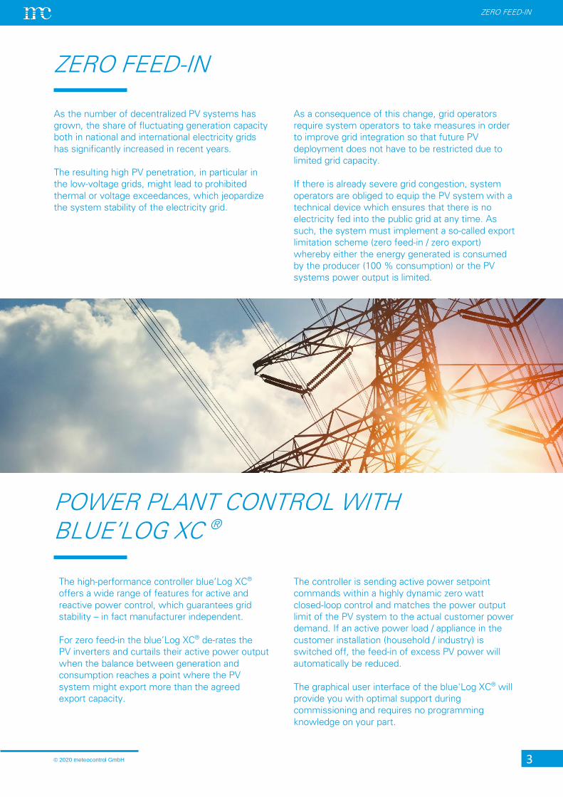
As the number of decentralized PV systems has
grown, the share of fluctuating generation capacity
both in national and international electricity grids
has significantly increased in recent years.
The resulting high PV penetration, in particular in
the low-voltage grids, might lead to prohibited
thermal or voltage exceedances, which jeopardize
the system stability of the electricity grid.
As a consequence of this change, grid operators
require system operators to take measures in order
to improve grid integration so that future PV
deployment does not have to be restricted due to
limited grid capacity.
If there is already severe grid congestion, system
operators are obliged to equip the PV system with a
technical device which ensures that there is no
electricity fed into the public grid at any time. As
such, the system must implement a so-called export
limitation scheme (zero feed-in / zero export)
whereby either the energy generated is consumed
by the producer (100 % consumption) or the PV
systems power output is limited.
The high-performance controller blue’Log XC®
offers a wide range of features for active and
reactive power control, which guarantees grid
stability – in fact manufacturer independent.
For zero feed-in the blue’Log XC® de-rates the
PV inverters and curtails their active power output
when the balance between generation and
consumption reaches a point where the PV
system might export more than the agreed
export capacity.
The controller is sending active power setpoint
commands within a highly dynamic zero watt
closed-loop control and matches the power output
limit of the PV system to the actual customer power
demand. If an active power load / appliance in the
customer installation (household / industry) is
switched off, the feed-in of excess PV power will
automatically be reduced.
The graphical user interface of the blue'Log XC® will
provide you with optimal support during
commissioning and requires no programming
knowledge on your part.
© 2020 meteocontrol GmbH 4
ZERO FEED-IN
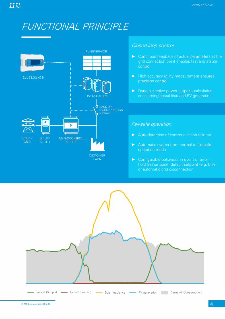
FUNCTIONAL PRINCIPLE
Fail-safe operation
► Auto-detection of communication failures
► Automatic switch from normal to fail-safe
operation mode
► Configurable behaviour in event of error -
hold last setpoint, default setpoint (e.g. 0 %)
or automatic grid disconnection
Closed-loop control
► Continous feedback of actual parameters at the
grid connection point enables fast and stable
control
► High-accuracy utility measurement ensures
precision control
► Dynamic active power setpoint calculation
considering actual load and PV generation
Import (Supply) Export (Feed-in) Solar irradiance PV generation Demand (Consumption)
ZERO FEED-IN
CONTROL DYNAMICS
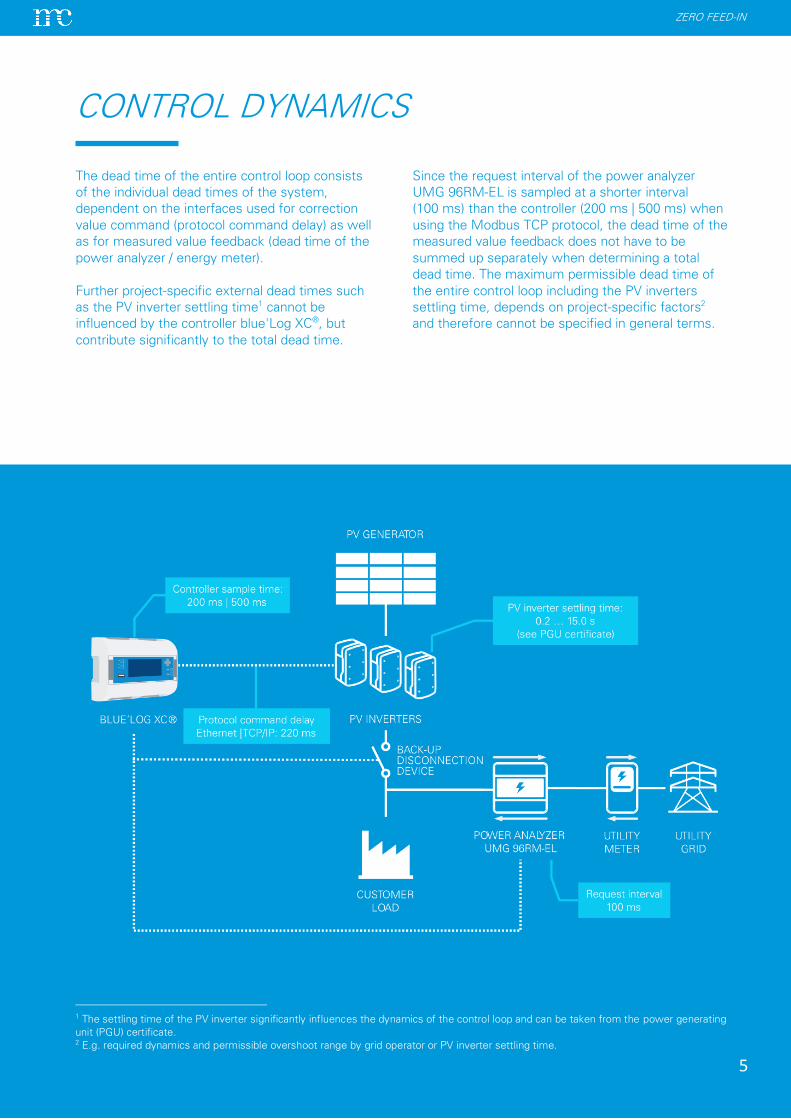
1 The settling time of the PV inverter significantly influences the dynamics of the control loop and can be taken from the power generating
unit (PGU) certificate. 2 E.g. required dynamics and permissible overshoot range by grid operator or PV inverter settling time.
The dead time of the entire control loop consists
of the individual dead times of the system,
dependent on the interfaces used for correction
value command (protocol command delay) as well
as for measured value feedback (dead time of the
power analyzer / energy meter).
Further project-specific external dead times such
as the PV inverter settling time1 cannot be
influenced by the controller blue'Log XC®, but
contribute significantly to the total dead time.
Since the request interval of the power analyzer
UMG 96RM-EL is sampled at a shorter interval
(100 ms) than the controller (200 ms | 500 ms) when
using the Modbus TCP protocol, the dead time of the
measured value feedback does not have to be
summed up separately when determining a total
dead time. The maximum permissible dead time of
the entire control loop including the PV inverters
settling time, depends on project-specific factors2
and therefore cannot be specified in general terms.
5
ZERO FEED-IN
REMOTE MONITORING WITH VCOM
SELF-CONSUMPTION RATIO
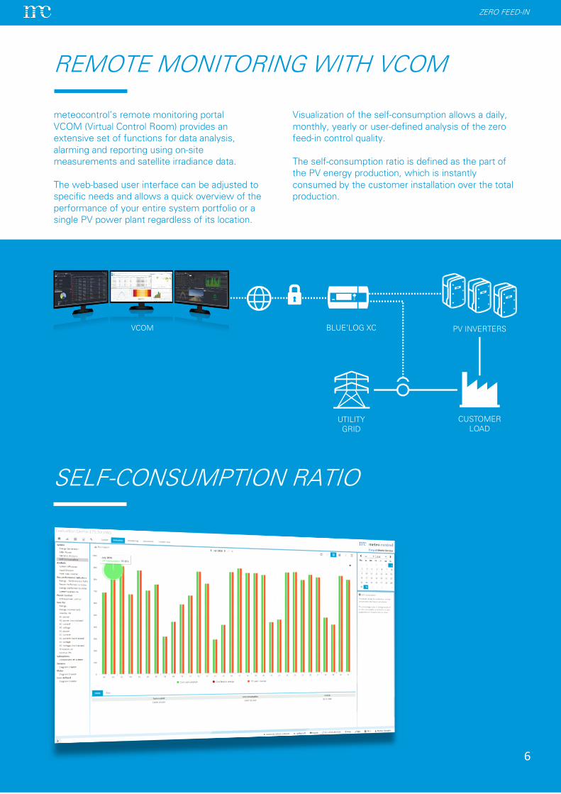
meteocontrol’s remote monitoring portal
VCOM (Virtual Control Room) provides an
extensive set of functions for data analysis,
alarming and reporting using on-site
measurements and satellite irradiance data.
The web-based user interface can be adjusted to
specific needs and allows a quick overview of the
performance of your entire system portfolio or a
single PV power plant regardless of its location.
Visualization of the self-consumption allows a daily,
monthly, yearly or user-defined analysis of the zero
feed-in control quality.
The self-consumption ratio is defined as the part of
the PV energy production, which is instantly
consumed by the customer installation over the total
production.
6
CUSTOMER
LOAD
BLUE’LOG XC PV INVERTERS
UTILITY
GRID
VCOMVCOM
© 2020 meteocontrol GmbH 7
ZERO FEED-IN
SYSTEM REQUIREMENTS
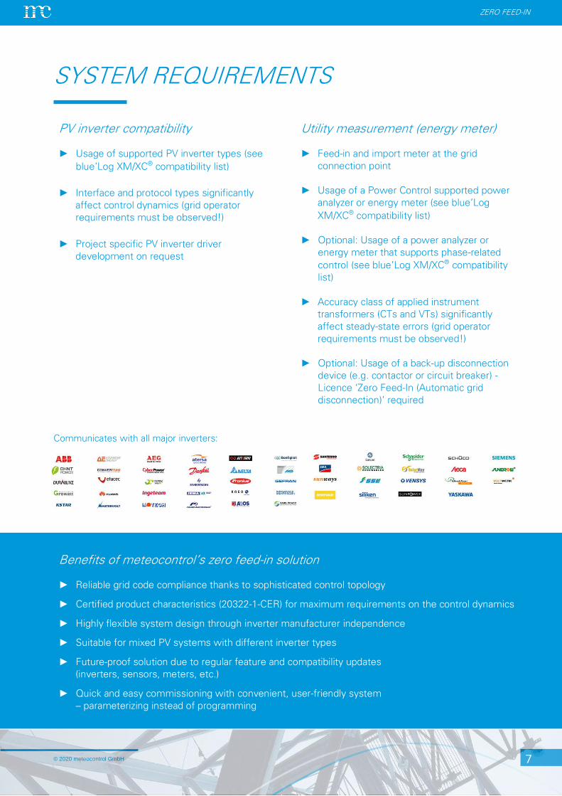
Communicates with all major inverters:
PV inverter compatibility
► Usage of supported PV inverter types (see
blue’Log XM/XC® compatibility list)
► Interface and protocol types significantly
affect control dynamics (grid operator
requirements must be observed!)
► Project specific PV inverter driver
development on request
Utility measurement (energy meter)
► Feed-in and import meter at the grid
connection point
► Usage of a Power Control supported power
analyzer or energy meter (see blue’Log
XM/XC® compatibility list)
► Optional: Usage of a power analyzer or
energy meter that supports phase-related
control (see blue’Log XM/XC® compatibility
list)
► Accuracy class of applied instrument
transformers (CTs and VTs) significantly
affect steady-state errors (grid operator
requirements must be observed!)
► Optional: Usage of a back-up disconnection
device (e.g. contactor or circuit breaker) -
Licence ‘Zero Feed-In (Automatic grid
disconnection)’ required
Benefits of meteocontrol’s zero feed-in solution
► Reliable grid code compliance thanks to sophisticated control topology
► Certified product characteristics (20322-1-CER) for maximum requirements on the control dynamics
► Highly flexible system design through inverter manufacturer independence
► Suitable for mixed PV systems with different inverter types
► Future-proof solution due to regular feature and compatibility updates
(inverters, sensors, meters, etc.)
► Quick and easy commissioning with convenient, user-friendly system
– parameterizing instead of programming