Embed Size (px)
Citation preview
Meter Gateway
V3.0.003
Version 3.0.003 17th December 2014
Electrocom
Vindebyørevej 1 5700 Svendborg Tel.: +45 8880 7580 www.electrocom.dk
p. 2
Introduction ................................................................................................................................................................... 3
Hardware Installation ................................................................................................................................................. 4
Configuration ................................................................................................................................................................. 5
Network Installation ....................................................................................................................................................... 5
Meter Gateway Configuration ................................................................................................................................... 5
TREND Network Setup ................................................................................................................................................. 6
Time synchronization .................................................................................................................................................... 7
Setting the time manually ...................................................................................................................................... 7
Time master synchronization ............................................................................................................................... 7
M-Bus Configuration ...................................................................................................................................................... 8
M-Bus Meter Setup .................................................................................................................................................. 9
M-Bus Meter Value Selection ............................................................................................................................ 10
Meter Configuration ................................................................................................................................................... 11
Edit node number for a meter .......................................................................................................................... 11
De-/Activate Plot .................................................................................................................................................... 12
Reset of a plot .......................................................................................................................................................... 12
Input/output Configuration ..................................................................................................................................... 13
Projecting .................................................................................................................................................................... 14
Troubleshooting ........................................................................................................................................................ 16
Inputs ................................................................................................................................................................................ 16
Meters .............................................................................................................................................................................. 16
p. 3
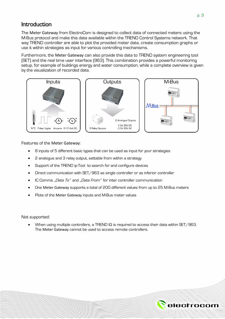
Introduction
The Meter Gateway from ElectroCom is designed to collect data of connected meters using the
M-Bus protocol and make this data available within the TREND Control Systems network. That way TREND controller are able to plot the provided meter data, create consumption graphs or use it within strategies as input for various controlling mechanisms.
Furthermore, the Meter Gateway can also provide this data to TREND system engineering tool
(SET) and the real time user interface (963). This combination provides a powerful monitoring setup, for example of buildings energy and water consumption, while a complete overview is given by the visualization of recorded data.
Features of the Meter Gateway:
8 inputs of 5 different basic types that can be used as input for your strategies
2 analogue and 3 relay output, settable from within a strategy
Support of the TREND ip-Tool to search for and configure devices
Direct communication with SET/963 as single controller or as inferior controller
IC Comms „Data To“ and „Data From“ for inter controller communication
One Meter Gateway supports a total of 200 different values from up to 25 M-Bus meters
Plots of the Meter Gateway inputs and M-Bus meter values
Not supported:
When using multiple controllers, a TREND IQ is required to access their data within SET/963.
The Meter Gateway cannot be used to access remote controllers.
p. 4
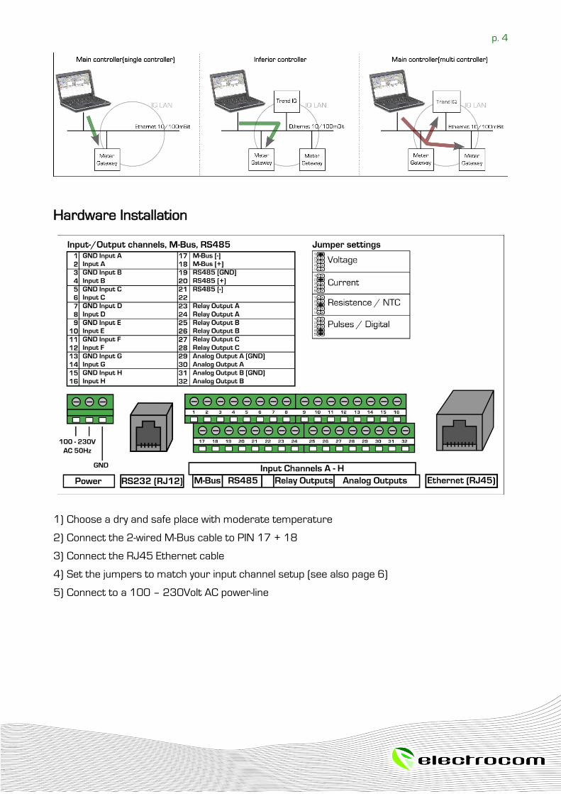
Hardware Installation
1) Choose a dry and safe place with moderate temperature
2) Connect the 2-wired M-Bus cable to PIN 17 + 18
3) Connect the RJ45 Ethernet cable
4) Set the jumpers to match your input channel setup (see also page 6)
5) Connect to a 100 – 230Volt AC power-line
p. 5
Configuration
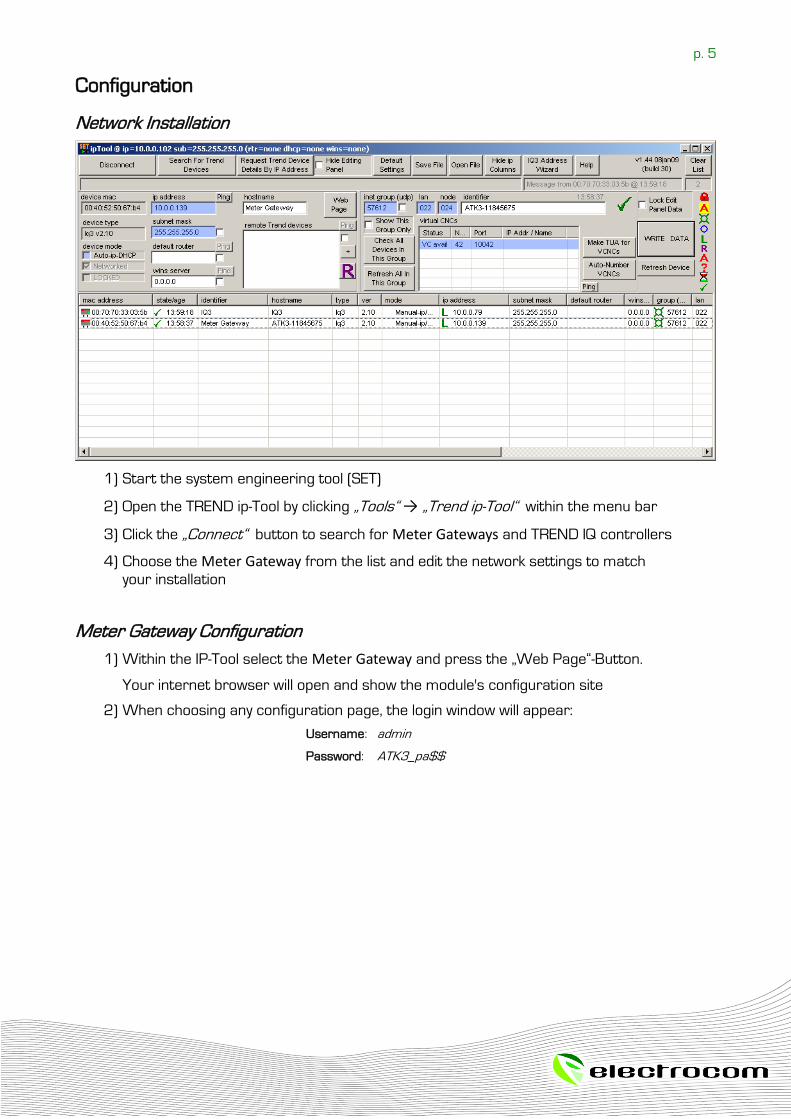
Network Installation
1) Start the system engineering tool (SET)
2) Open the TREND ip-Tool by clicking „Tools“ → „Trend ip-Tool“ within the menu bar
3) Click the „Connect“ button to search for Meter Gateways and TREND IQ controllers
4) Choose the Meter Gateway from the list and edit the network settings to match
your installation
Meter Gateway Configuration
1) Within the IP-Tool select the Meter Gateway and press the „Web Page“-Button.
Your internet browser will open and show the module's configuration site
2) When choosing any configuration page, the login window will appear:
Username: admin
Password: ATK3_pa$$
p. 6
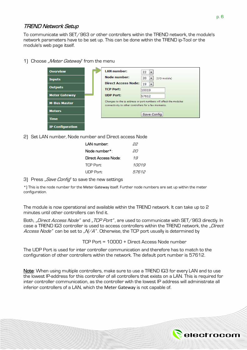
TREND Network Setup
To communicate with SET/963 or other controllers within the TREND network, the module's network parameters have to be set up. This can be done within the TREND ip-Tool or the module's web page itself.
1) Choose „Meter Gateway“ from the menu
2) Set LAN number, Node number and Direct access Node
LAN number: 22
Node number*: 20
Direct Access Node: 19
TCP Port: 10019
UDP Port: 57612
3) Press „Save Config“ to save the new settings
*) This is the node number for the Meter Gateway itself. Further node numbers are set up within the meter
configuration.
The module is now operational and available within the TREND network. It can take up to 2 minutes until other controllers can find it.
Both, „Direct Access Node“ and „TCP Port“ , are used to communicate with SET/963 directly. In case a TREND IQ3 controller is used to access controllers within the TREND network, the „Direct Access Node“ can be set to „N/A“ . Otherwise, the TCP port usually is determined by TCP Port = 10000 + Direct Access Node number
The UDP Port is used for inter controller communication and therefore has to match to the configuration of other controllers within the network. The default port number is 57612.
Note: When using multiple controllers, make sure to use a TREND IQ3 for every LAN and to use the lowest IP-address for this controller of all controllers that exists on a LAN. This is required for inter controller communication, as the controller with the lowest IP address will administrate all
inferior controllers of a LAN, which the Meter Gateway is not capable of.
p. 7
Time synchronization
Before the first installation or after a power loss, the Meter Gateways locale time will be out of
sync. There are two possible ways to synchronize the modules local time with the real time. It can be synchronized manually within the web setup or by receiving time synchronization from a time master within the TREND network.
Setting the time manually
Within the web setup:
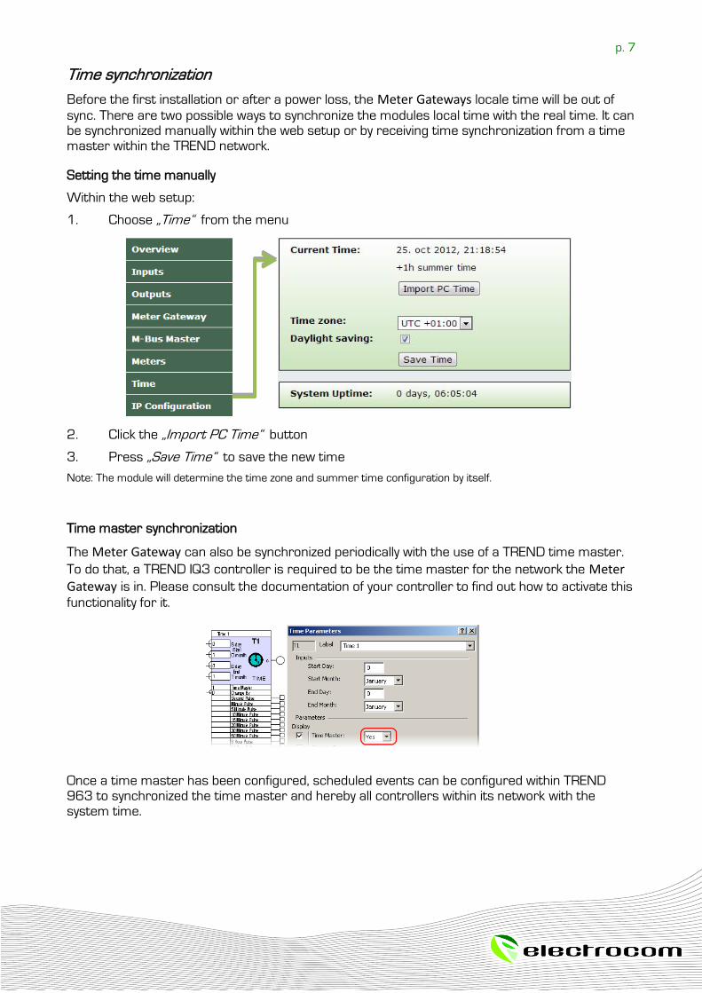
1. Choose „Time“ from the menu
2. Click the „Import PC Time“ button
3. Press „Save Time“ to save the new time
Note: The module will determine the time zone and summer time configuration by itself.
Time master synchronization
The Meter Gateway can also be synchronized periodically with the use of a TREND time master.
To do that, a TREND IQ3 controller is required to be the time master for the network the Meter Gateway is in. Please consult the documentation of your controller to find out how to activate this
functionality for it.
Once a time master has been configured, scheduled events can be configured within TREND 963 to synchronized the time master and hereby all controllers within its network with the system time.
p. 8
M-Bus Configuration
The Meter Gateway is representing each M-Bus meter that is connected and configured to the
gateway as an independent node in the TREND network. To search for and configure the meters the M-Bus interface needs to be set up.
Meters can be connected to the Meter Gateway in two different ways. The easiest way is to
connect the M-Bus line directly to the gateway. The module will supply the M-Bus line and thereby all meters on the line. Depending on the unit load of the meters, it might be necessary to use an M-Bus level converter like the PW60 of Relay, which has a bigger power supply. To still be able to connect the meters to the gateway, the RS232 serial interface can be used to establish a link to the level converter.
Follow these steps to configure the interface:
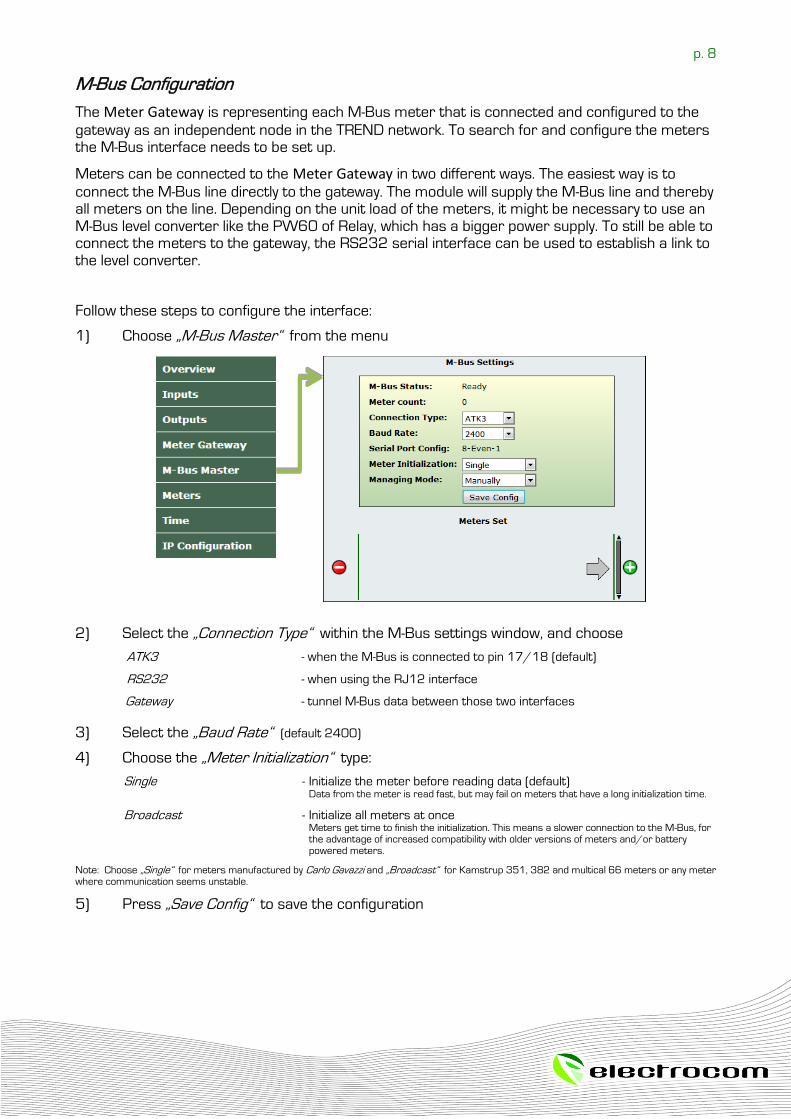
1) Choose „M-Bus Master“ from the menu
2) Select the „Connection Type“ within the M-Bus settings window, and choose
ATK3 - when the M-Bus is connected to pin 17/18 (default)
RS232 - when using the RJ12 interface
Gateway - tunnel M-Bus data between those two interfaces
3) Select the „Baud Rate“ (default 2400)
4) Choose the „Meter Initialization“ type:
Single - Initialize the meter before reading data (default) Data from the meter is read fast, but may fail on meters that have a long initialization time.
Broadcast - Initialize all meters at once Meters get time to finish the initialization. This means a slower connection to the M-Bus, for
the advantage of increased compatibility with older versions of meters and/or battery powered meters.
Note: Choose „Single“ for meters manufactured by Carlo Gavazzi and „Broadcast“ for Kamstrup 351, 382 and multical 66 meters or any meter where communication seems unstable.
5) Press „Save Config“ to save the configuration
p. 9
M-Bus Meter Setup
When installing the Meter Gateway for the first time, there are no M-Bus meters registered to it.
To find connected meters, the Gateway offers two managing modes - Manually and Automatic.
When choosing the first option, the user can add M-Bus meters manually.
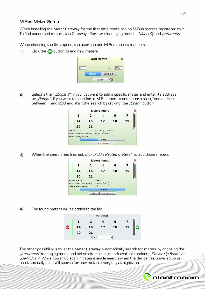
1) Click the button to add new meters
2) Select either „Single #“ if you just want to add a specific meter and enter its address,
or „Range“ , if you want to scan for all M-Bus meters and enter a start/end address between 1 and 250 and start the search by clicking the „Scan“ button
3) When the search has finished, click „Add selected meters“ to add those meters
4) The found meters will be added to the list
The other possibility is to let the Meter Gateway automatically search for meters by choosing the
„Automatic“ managing mode and select either one or both available options, „Power Up Scan“ or „Daily Scan“. While power up scan initiates a single search when the device has powered up or reset, the daily scan will search for new meters every day at nighttime.
p. 10
M-Bus Meter Value Selection
To support as much data points as possible, the Meter Gateway can filter unnecessary meter
values that are of no interest to free memory for other data points and that way speed up the overall performance. The number of available data points can be found within the „Meter Setup“.
As one is most of the time only interested in a few values of a meter, all additional data points a meter usually has, can be removed.
To remove a value:
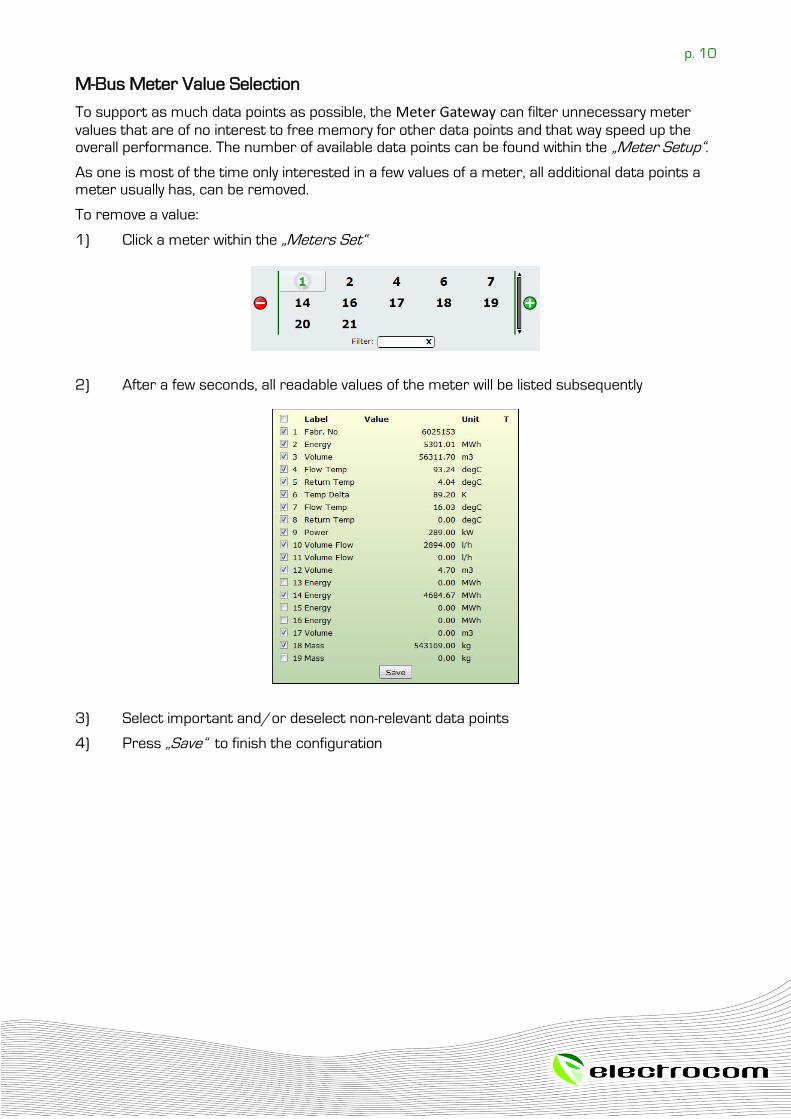
1) Click a meter within the „Meters Set“
2) After a few seconds, all readable values of the meter will be listed subsequently
3) Select important and/or deselect non-relevant data points
4) Press „Save“ to finish the configuration
p. 11
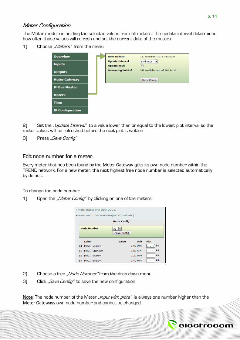
Meter Configuration
The Meter module is holding the selected values from all meters. The update interval determines how often those values will refresh and set the current data of the meters.
1) Choose „Meters“ from the menu
2) Set the „Update Interval“ to a value lower than or equal to the lowest plot interval so the meter values will be refreshed before the next plot is written
3) Press „Save Config“
Edit node number for a meter
Every meter that has been found by the Meter Gateway gets its own node number within the
TREND network. For a new meter, the next highest free node number is selected automatically by default.
To change the node number:
1) Open the „Meter Config“ by clicking on one of the meters
2) Choose a free „Node Number“ from the drop-down menu
3) Click „Save Config“ to save the new configuration
Note: The node number of the Meter „Input with plots“ is always one number higher than the
Meter Gateways own node number and cannot be changed.
p. 12
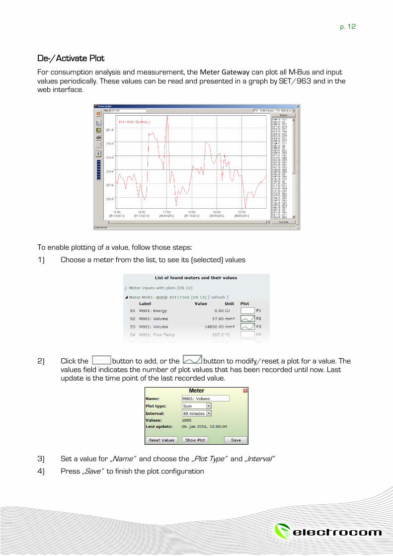
De-/Activate Plot
For consumption analysis and measurement, the Meter Gateway can plot all M-Bus and input
values periodically. These values can be read and presented in a graph by SET/963 and in the web interface.
To enable plotting of a value, follow those steps:
1) Choose a meter from the list, to see its (selected) values
2) Click the button to add, or the button to modify/reset a plot for a value. The values field indicates the number of plot values that has been recorded until now. Last update is the time point of the last recorded value.
3) Set a value for „Name“ and choose the „Plot Type“ and „Interval“
4) Press „Save“ to finish the plot configuration
p. 13
Reset of a plot
In case you want to delete all recorded values, for example when your strategy has changed, press the „Reset Values“ button.
Warning: The reset of values is final and cannot be undone
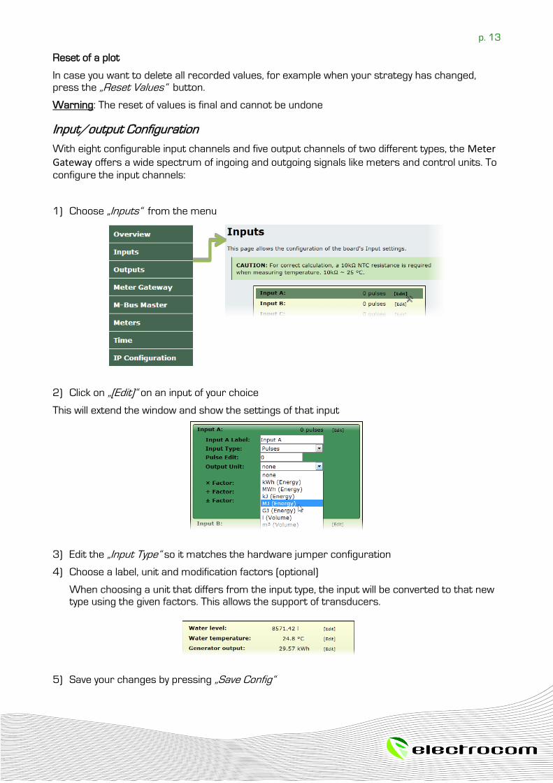
Input/output Configuration
With eight configurable input channels and five output channels of two different types, the Meter Gateway offers a wide spectrum of ingoing and outgoing signals like meters and control units. To
configure the input channels: 1) Choose „Inputs“ from the menu
2) Click on „[Edit]“ on an input of your choice
This will extend the window and show the settings of that input
3) Edit the „Input Type“ so it matches the hardware jumper configuration
4) Choose a label, unit and modification factors (optional)
When choosing a unit that differs from the input type, the input will be converted to that new type using the given factors. This allows the support of transducers.
5) Save your changes by pressing „Save Config“
p. 14
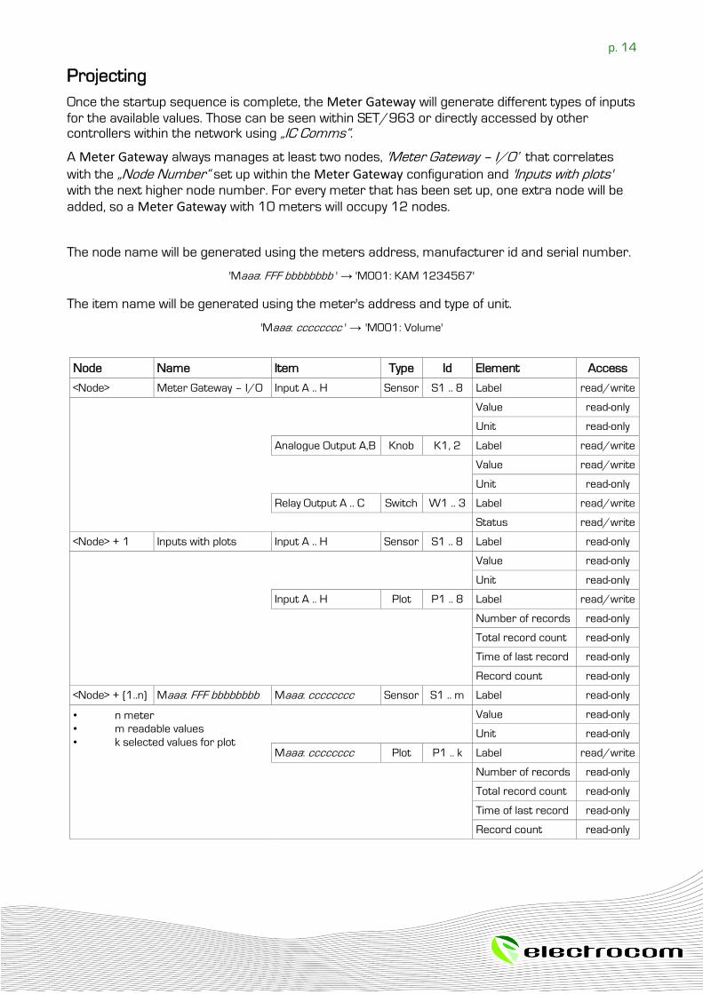
Projecting
Once the startup sequence is complete, the Meter Gateway will generate different types of inputs
for the available values. Those can be seen within SET/963 or directly accessed by other controllers within the network using „IC Comms“.
A Meter Gateway always manages at least two nodes, 'Meter Gateway – I/O’ that correlates
with the „Node Number“ set up within the Meter Gateway configuration and 'Inputs with plots' with the next higher node number. For every meter that has been set up, one extra node will be
added, so a Meter Gateway with 10 meters will occupy 12 nodes.
The node name will be generated using the meters address, manufacturer id and serial number.
'Maaa: FFF bbbbbbbb ' → 'M001: KAM 1234567'
The item name will be generated using the meter's address and type of unit.
'Maaa: cccccccc ' → 'M001: Volume'
Node Name Item Type Id Element Access
<Node> Meter Gateway – I/O Input A .. H Sensor S1 .. 8 Label read/write
Value read-only
Unit read-only
Analogue Output A,B Knob K1, 2 Label read/write
Value read/write
Unit read-only
Relay Output A .. C Switch W1 .. 3 Label read/write
Status read/write
<Node> + 1 Inputs with plots Input A .. H Sensor S1 .. 8 Label read-only
Value read-only
Unit read-only
Input A .. H Plot P1 .. 8 Label read/write
Number of records read-only
Total record count read-only
Time of last record read-only
Record count read-only
<Node> + (1..n) Maaa: FFF bbbbbbbb Maaa: cccccccc Sensor S1 .. m Label read-only
• n meter
• m readable values
• k selected values for plot
Value read-only
Unit read-only
Maaa: cccccccc Plot P1 .. k Label read/write
Number of records read-only
Total record count read-only
Time of last record read-only
Record count read-only
p. 15
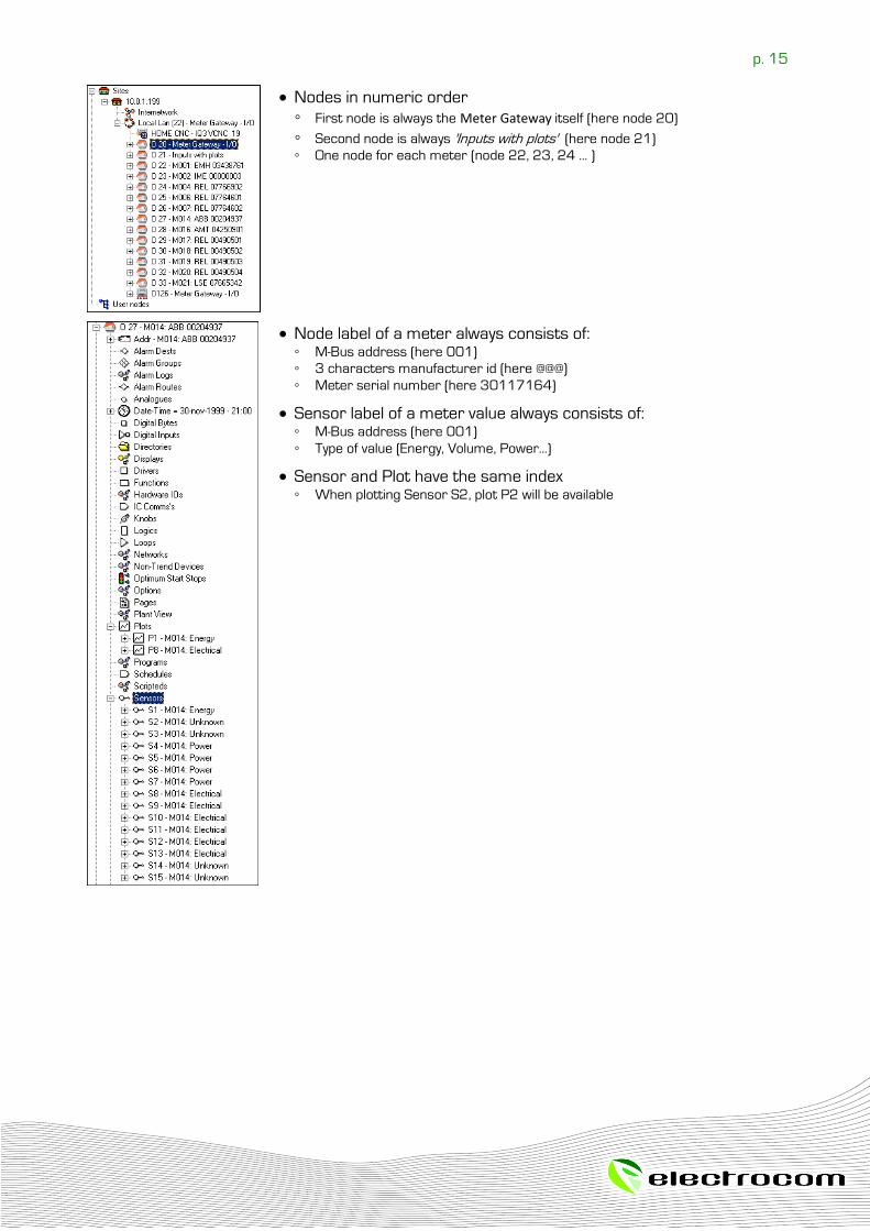
Nodes in numeric order
First node is always the Meter Gateway itself (here node 20)
Second node is always 'Inputs with plots' (here node 21) One node for each meter (node 22, 23, 24 ... )
Node label of a meter always consists of: M-Bus address (here 001)
3 characters manufacturer id (here @@@)
Meter serial number (here 30117164)
Sensor label of a meter value always consists of: M-Bus address (here 001)
Type of value (Energy, Volume, Power...)
Sensor and Plot have the same index When plotting Sensor S2, plot P2 will be available
p. 16
Troubleshooting
Inputs
Problem: What are the NTC resistance and the B-parameter? Solution:
• The inputs supports a NTC with the following specifications
Resistance: 10kΩ
B value: 4300
Meters
Problem: While scanning some M-Bus meters were found, but others are missing. Solution:
• Try to scan for the missing meters using another baud rate
In case the missing meters can be found now, set the baud rate of all meters to the same value (on most
meters, the used baud rate can be setup)
Should the missing meters still not appear, chances are there is an error within the setup. Check the
meters using tools like MB-Sheet from Relay in combination with a PW20/60 module to see if communication to the meter is possible and the meter is set up correctly (primary address different from
0)
Problem: The scan does not find any M-Bus meters. Solution:
• Do all meters have a primary address set, which is different to zero (factory default)?
If not, set a unique primary address for every meter using tools like MB-Sheet from Relay in combination
with a PW20/60 module
• While scanning, is there any activity on the M-Bus LEDs?
The TX LED will blink periodically for every slave id that is tested
The RX LED will blink only, when there's a slave answering
The LED D will light up constantly when a M-Bus request is in progress and therefore should light up until the scan is finished
Problem: When starting a scan for M-Bus meters, the progress gets stuck at "Initiate scan.." Solution:
• This can be the result of cached data within the browser. Clean your browser cache or press Ctrl + F5 to reload the page. Reinitialize the scan.
• The yellow LED C will light up, while the Meter Gateway is communicating with the M-Bus
Problem: Does the M-Bus interface support L-Bus (Local Bus) Solution:
• The M-Bus interface follows the specifications in EN 13757-2
• L-Bus interface is EN 13757-6
The two interfaces are not compatible because they have different voltage levels