Embed Size (px)
Citation preview

Method of mechanical holding of cantilever chip for tip-scan high-speed atomic forcemicroscopeShingo Fukuda, Takayuki Uchihashi, and Toshio Ando Citation: Review of Scientific Instruments 86, 063703 (2015); doi: 10.1063/1.4922381 View online: http://dx.doi.org/10.1063/1.4922381 View Table of Contents: http://scitation.aip.org/content/aip/journal/rsi/86/6?ver=pdfcov Published by the AIP Publishing Articles you may be interested in Note: High-speed Z tip scanner with screw cantilever holding mechanism for atomic-resolution atomic forcemicroscopy in liquid Rev. Sci. Instrum. 85, 126106 (2014); 10.1063/1.4904029 High-speed imaging upgrade for a standard sample scanning atomic force microscope using small cantilevers Rev. Sci. Instrum. 85, 093702 (2014); 10.1063/1.4895460 Piezoelectric bimorph-based scanner in the tip-scan mode for high speed atomic force microscope Rev. Sci. Instrum. 84, 083706 (2013); 10.1063/1.4818976 Tip-sample distance control using photothermal actuation of a small cantilever for high-speed atomic forcemicroscopy Rev. Sci. Instrum. 78, 083702 (2007); 10.1063/1.2766825 A mechanical microscope: High-speed atomic force microscopy Appl. Phys. Lett. 86, 034106 (2005); 10.1063/1.1855407
This article is copyrighted as indicated in the article. Reuse of AIP content is subject to the terms at: http://scitationnew.aip.org/termsconditions. Downloaded to IP:
133.28.47.30 On: Fri, 12 Jun 2015 14:36:55

REVIEW OF SCIENTIFIC INSTRUMENTS 86, 063703 (2015)
Method of mechanical holding of cantilever chip for tip-scan high-speedatomic force microscope
Shingo Fukuda,1 Takayuki Uchihashi,1,2,3 and Toshio Ando1,2,31Department of Physics, College of Science and Engineering, Kanazawa University,Kakuma-machi, Kanazawa 920-1192, Japan2Bio-AFM Frontier Research Center, College of Science and Engineering, Kanazawa University,Kakuma-machi, Kanazawa 920-1192, Japan3Core Research for Evolutional Science and Technology of the Japan Science and Technology Agency,7 Goban-cho, Chiyoda-ku, Tokyo 102-0076, Japan
(Received 23 February 2015; accepted 31 May 2015; published online 11 June 2015)
In tip-scan atomic force microscopy (AFM) that scans a cantilever chip in the three dimensions, thechip body is held on the Z-scanner with a holder. However, this holding is not easy for high-speed(HS) AFM because the holder that should have a small mass has to be able to clamp the cantileverchip firmly without deteriorating the Z-scanner’s fast performance, and because repeated exchange ofcantilever chips should not damage the Z-scanner. This is one of the reasons that tip-scan HS-AFMhas not been established, despite its advantages over sample stage-scan HS-AFM. Here, we presenta novel method of cantilever chip holding which meets all conditions required for tip-scan HS-AFM.The superior performance of this novel chip holding mechanism is demonstrated by imaging ofthe α3β3 subcomplex of F1-ATPase in dynamic action at ∼7 frames/s. C 2015 AIP PublishingLLC. [http://dx.doi.org/10.1063/1.4922381]
I. INTRODUCTION
High-speed atomic force microscopy (HS-AFM) was es-tablished around 20081 through long-range efforts to increasethe response speed of cantilevers,2,3 the scanner,4–7 and elec-tronics,1,2,8 as well as to make the high-speed performancecompatible with low-invasiveness to fragile samples9 (see re-views1,10,11). This established HS-AFM has mainly been usedto observe protein molecules in dynamic action at sub-100 msto subsecond time resolution. For example, bacteriorhodopsinresponding to light,12 myosin V walking on actin filaments,13
and rotor-less F1-ATPase (i.e., the α3β3 subcomplex of F1-ATPase) with directional chemical-state rotation over thethree β subunits14 have been visualized (see reviews15,16).These observations have provided greater insights than everbefore into how the proteins function, thus demonstratingthe innovative power of this microscopy. Recently, fast wide-area scanners displaceable up to 23 × 23 µm2 or up to ∼50× 50 µm2 have been developed17,18 together with a new vibra-tion damping method for the wide-area scanners,18 expandingthe objects of HS-AFM observation to much larger ones. Forexample, various dynamic processes occurring in live bacterialand mammalian cells, such as endocytosis, membrane raffling,filopodia growth and bacteriolysis, were visualized withina few seconds.18,19 The HS-AFM instrument used in thesestudies employs the sample stage-scan mode. To achieve thehigh scan rate and minimize the hydrodynamic effect of fastsample-stage movement on the cantilever behavior, a smallsample stage (a glass rod with dimensions of 1–1.5 mm indiameter and 2 mm in height) is attached to the Z-scanner.This small size limits the range of specimens to be placed onthe sample stage. Moreover, when the HS-AFM instrument iscombined with an optical microscope, the optical image of thesample oscillates during HS-AFM imaging. More seriously,
various optical microscopy techniques are incompatible withthe configuration of mechanical and optical devices in theHS-AFM instrument, restricting the functional expansion ofHS-AFM.
To overcome these limitations associated with the sam-ple stage-scan mode, tip-scan HS-AFM has recently beenattempted to be developed. One of the common requirementsof tip-scan AFM that employs the widely used optical levermethod of detecting cantilever’s deflection is that the laserbeam focused onto the cantilever should be able to track thelateral motion of the cantilever. This tracking adoptable totip-scan HS-AFM was recently accomplished by laser beamscan in synchrony with the cantilever’s lateral motion usingeither a mirror tilter20 or a focusing lens embedded in theXY-scanner.21 The combined system of total internal reflec-tion fluorescence microscopy (TIRFM) and tip-scan HS-AFMequipped with the mirror tilter was demonstrated to be ableto capture topographic AFM and single-molecule fluorescentimages simultaneously at a few frames/s (fps).20 Thus, tip-scanHS-AFM opened new opportunities to observe dynamic eventsin a large specimen placed on the stage of an inverted opticalmicroscope as well as to combine HS-AFM with various opti-cal techniques, such as super-resolution fluorescence micros-copy techniques22,23 and even optical tweezers.24
Nevertheless, an important issue, which is seemingly sim-ple but practically difficult to resolve, has remained to beaccomplished. That is, how to attach a cantilever chip firmlyonto the fast, lightweight Z-scanner, without deteriorating thefast, precise response of the Z-scanner. As a matter of course,one can firmly glue a cantilever chip onto the Z-scanner, ashas been done in the above tip-scan HS-AFM/TIRFM experi-ments. However, the chip has to be frequently replaced with anew one, and therefore, this method is inadequate for routineuse. The use of thermoplastic adhesives is one possibility.
0034-6748/2015/86(6)/063703/7/$30.00 86, 063703-1 © 2015 AIP Publishing LLC This article is copyrighted as indicated in the article. Reuse of AIP content is subject to the terms at: http://scitationnew.aip.org/termsconditions. Downloaded to IP:
133.28.47.30 On: Fri, 12 Jun 2015 14:36:55

063703-2 Fukuda, Uchihashi, and Ando Rev. Sci. Instrum. 86, 063703 (2015)
However, the adhesives cannot be removed completely butpartially remain after removal of the cantilever and gradu-ally age by repeated heating, resulting in a rough surface ofthe Z-scanner’s top face. Moreover, when the cantilever isimmersed in a buffer solution, such adhesives contaminate thesolution. The conditions required for the method of holdinga cantilever chip are as follows: (i) a cantilever chip bodyhas to be firmly clamped so that the chip does not generateunwanted vibrations during fast scanning of the Z-scanner,(ii) the cantilever chip holder has to have a small mass and thefirst resonant frequency higher than that of the Z-scanner, (iii) acantilever chip has to be easily attached onto and removedfrom the Z-scanner so that the scanner would not be damagedduring these operations, and (iv) the cantilever chip holdershould be durable without aging and wear so as to be usedrepeatedly.
Magnetic or vacuum clamp may be a possible candidatebut magnetic clamp requires ferromagnetic coating of a canti-lever chip, which is inadequate for routine use, while vacuumclamp is too weak to hold a cantilever chip firmly enoughnot to generate unwanted vibrations. Therefore, mechanicalclamp seems to be a only candidate that would meet all therequired conditions. However, the entire body of the mechan-ical clamping system cannot be mounted directly on the Z-scanner. This is partly because the mass effect of this mountingwould significantly reduce the resonant frequency of the Z-scanner and primarily because repeated exchange of cantileverchips would damage the Z-scanner (e.g., the Z-piezoactuator isunglued from the supporting base). In fact, this way of mount-ing was recently shown by Fukuma’s group to deteriorate the
frequency response of the Z-scanner even in the best caseamong various designs.25 Our group also has experienced thisproblem as well as the damaging problem. Therefore, we heretested methods in which a cantilever chip clamping systemwas indirectly mounted on the Z-scanner and reached a designthat did not affect the fast, precise response of the Z-scanner.This excellent performance was demonstrated by imaging ofprotein molecules in dynamic action.
II. EXPERIMENTAL SETUP
The scanner used here is similar to that developed previ-ously for tip-scan HS-AFM,20 except its modification forcantilever chip holding. Briefly, for the Z-scanner, the stackpiezoactuator (AE0203D04F Tokin-NEC, Miyagi, Japan) isused that has dimensions 2 × 3 × 5 mm3, the measured firstresonant frequency in free oscillation 222 kHz (nominally 261kHz), and the measured displacement efficiency 18.2 nm/V(nominal maximum displacement, 4.6 µm at 150 V). ThisZ-piezoactuator is glued onto the top of the supporting baseto be scanned in the X- and Y-directions. The same typeof a piezoactuator (Z′-piezoactuator) is also glued onto thebottom of the supporting base to counteract the impulsive forceproduced by quick displacement of the Z-piezoactuator.3 Thegap space in the scanner is filled with an elastomer having ahigh loss factor to absorb the mechanical vibration energy.18
A wedge-shaped stage (hereafter referred to as “w-stage”) onwhich a cantilever chip to be placed is glued onto the top ofthe Z-scanner. This w-stage (32 mg) is made of silicon car-bide with a high Young’s modulus-to-density ratio (Young’s
FIG. 1. Experimental setup for the characterization of Z-scanner’s frequency response. (i) Frequency response analyzer (FRA) simultaneously drives the Z- andZ′-piezoactuators with sinusoidal waves at various frequencies through a high-bandwidth piezodriver. (ii) The laser displacement sensor detects the displacementof target portions (i.e., the top face of the Z-scanner without both w-stage and cantilever chip holder, the top face of the w-stage, and the distal portion of thecantilever chip body). (iii) The FRA calculates the gain and phase of the signal from the sensor. The phase is relative to the driving signal.
This article is copyrighted as indicated in the article. Reuse of AIP content is subject to the terms at: http://scitationnew.aip.org/termsconditions. Downloaded to IP:
133.28.47.30 On: Fri, 12 Jun 2015 14:36:55

063703-3 Fukuda, Uchihashi, and Ando Rev. Sci. Instrum. 86, 063703 (2015)
modulus, ∼430 GPa; density, ∼3.2 g/cm3). The wedge angleis 20◦, so that the mounted cantilever is tilted by this anglewith respect to the sample substrate. To facilitate guiding ofa cantilever chip onto the w-stage, a shallow groove slightlywider than the cantilever chip is cut on the top face of thew-stage. Another wedge-shaped stage (w′-stage) identical tothe w-stage is also glued on the top of the Z′-piezoactuator ascounterweight.
The experimental setup for analyzing the frequency re-sponses described below is illustrated in Fig. 1. For the fre-quency response analysis, a frequency response analyzer(FRA5097, NF Corp., Kanagawa, Japan) was used. For theanalysis of the frequency response of the Z-scanner itself,the w- and w′-stages were removed from the Z- and Z′-piezoactuators, respectively. The Z- and Z′-piezoactuatorswere simultaneously and sinusoidally oscillated in synchronywith each other at amplitude of 6 nm and frequencies of0–400 kHz through a high-bandwidth (∼1 MHz) piezodriver(M-2335, custom-made, Mess-Tek. Corp., Saitama, Japan).A heterodyne laser displacement sensor (ST-3761, IWATSU,Tokyo, Japan) was used to measure mechanical vibrationsoccurring at target portions. Its laser beam was incident onthe Z-scanner without the w- and w′-stages, the w-stage gluedonto the Z-scanner (the w′-wage was also glued to the Z′-piezoactuator) or the cantilever chip (BL-AC7DS-KU5,custom-made, Olympus, Tokyo, Japan) clamped on the w-stage with either of the two cantilever chip holding mecha-nisms described below (note that an identical cantilever chipwas glued to the w′-stage as counterweight). For the measure-ment of cantilever chip vibrations, the laser was incident onthe cantilever chip body at a distal position from which thecantilever extends. Note that for the vibration measurements,we could not use the optical beam deflection sensor equippedin our tip-scan HS-AFM instrument because this sensor detectsan angle change of the target rather than its displacement. Thesolid lines in Fig. 2 show the frequency response of the Z-scanner itself, indicating the first resonant frequency of theone-end-fixed Z-piezoactuator, 110 kHz, as expected fromthe measured resonant frequency of the piezoactuator in freeoscillation, 222 kHz. The attachment of the w-stage on the topof the Z-scanner only slightly changed the frequency responseof the Z-scanner, as shown with the dotted lines in Fig. 2.
FIG. 2. Frequency responses of one-end-fixed Z-piezoactuator with andwithout w-stage. The solid lines (red line, gain; blue line, phase) indicatethe frequency response in the case without w-stage, while the dotted lines(red line, gain; blue line, phase) indicate the frequency response in the casewith the w-stage.
III. CANTILEVER CHIP HOLDING MECHANISMS
To avoid damaging the Z-scanner by repeated exchange ofcantilever chips, the entire chip holder should not be directlymounted on the top of the Z-scanner. Otherwise, a pushingforce (or torque) exerted by an operator to the chip holder isdirectly applied onto the Z-scanner, often resulting in damageof the Z-scanner or ungluing of the holder from the Z-scanner.The entire mounting is also inadequate in another regard;it would result in that we have to clamp a cantilever chipfirmly with a small-sized lightweight mechanism. But, it isdifficult. When the holding mechanism is relatively heavy, itsignificantly impairs the Z-scanner’s resonant frequency; a Z-piezoactuator to be used for HS-AFM is small and its mass isapproximately in the range of 100–300 mg. As such, the chipholder should be supported on one prop or two props standingon the base block onto which the Z-piezoactuator is glued.Moreover, the holder should have a simple structure so as toachieve high resonant frequencies.
Considering these factors, we first designed a holdingmechanism in which the clamping system is supported ona single prop, as shown in Fig. 3. The prop was monolithi-cally fabricated on the base block mentioned above (stainlesssteel SUS303). The prop is positioned at the back of theZ-piezoactuator. The top face of the prop is slanted from thehorizontal plane at an angle the same as the wedge angle of
FIG. 3. Schematic diagram of the scanner with single-prop holding mechanism. (a) Side view, (b) top view, and (c) whole view. This article is copyrighted as indicated in the article. Reuse of AIP content is subject to the terms at: http://scitationnew.aip.org/termsconditions. Downloaded to IP:
133.28.47.30 On: Fri, 12 Jun 2015 14:36:55
063703-4 Fukuda, Uchihashi, and Ando Rev. Sci. Instrum. 86, 063703 (2015)
FIG. 4. Frequency responses of Z-scanner equipped with single-prop hold-ing mechanism with and without elastic polymer sheet on the beam springhead. The solid lines (red line, gain; blue line, phase) indicate the frequencyresponse in the case with the polymer sheet. The dotted lines (green, gain;purple, phase) indicate the frequency response in the case without the poly-mer sheet.
the w-stage, 20◦. The top part of the prop is internally threadedperpendicularly to the slanted plane. One end of a beam spring(stainless steel SUS303) with the total length of 7.15 mm isclamped on the slanted top face of the prop with a screw so thatthe cantilever inserted between the beam spring head and thew-stage is pushed down onto the w-stage. Note that the heightof the prop is adjusted so that clamping force can be appliedfrom the beam spring to the cantilever chip. That is, the topface of the prop is positioned lower by 0.1 mm than the topsurface of the installed cantilever chip body. To keep the beamspring head from touching the sample of observation, its distaledge region is cut aslant at an angle of 20◦. The dotted linesin Fig. 4 indicate the frequency response of the cantilever chipheld by this method, indicating appearance of an extra resonantpeak at ∼63 kHz, which is followed by a resonant peak at105 kHz that originates from the w-stage-mounted Z-scanneritself (compare the spectra to those shown with the dotted linesin Fig. 2). The extra resonant vibrations at ∼63 kHz indicatethat the cantilever chip vibrates at the resonant frequency of thebeam spring that insufficiently clamps the chip. This insuffi-ciency may result from incomplete contact between the surfaceof the beam spring head (0.8 × 1.9 mm2) and the cantileverchip body, which is very likely to be due to the deformationof the beam spring by clamping. To test this possibility andincrease the contact area, an elastic polymer sheet was attached
on the bottom surface of the beam spring head at its area to be incontact with the cantilever chip. This sheet (thickness∼50 µm)was prepared by thin coating of the beam spring head with anadhesive (Super-X, Cemedine, Tokyo, Japan) and then drying.As shown with the solid red lines in Fig. 4, the large resonantpeak at ∼63 kHz disappeared by this treatment, suggesting alarger clamp force as well as an additional role of the polymersheet as a vibration damper; however, small resonant peaksaround 50 kHz remained.
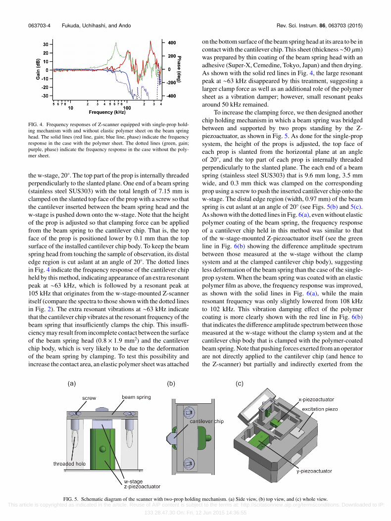
To increase the clamping force, we then designed anotherchip holding mechanism in which a beam spring was bridgedbetween and supported by two props standing by the Z-piezoactuator, as shown in Fig. 5. As done for the single-propsystem, the height of the props is adjusted, the top face ofeach prop is slanted from the horizontal plane at an angleof 20◦, and the top part of each prop is internally threadedperpendicularly to the slanted plane. The each end of a beamspring (stainless steel SUS303) that is 9.6 mm long, 3.5 mmwide, and 0.3 mm thick was clamped on the correspondingprop using a screw to push the inserted cantilever chip onto thew-stage. The distal edge region (width, 0.97 mm) of the beamspring is cut aslant at an angle of 20◦ (see Figs. 5(b) and 5(c).As shown with the dotted lines in Fig. 6(a), even without elasticpolymer coating of the beam spring, the frequency responseof a cantilever chip held in this method was similar to thatof the w-stage-mounted Z-piezoactuator itself (see the greenline in Fig. 6(b) showing the difference amplitude spectrumbetween those measured at the w-stage without the clampsystem and at the clamped cantilever chip body), suggestingless deformation of the beam spring than the case of the single-prop system. When the beam spring was coated with an elasticpolymer film as above, the frequency response was improved,as shown with the solid lines in Fig. 6(a), while the mainresonant frequency was only slightly lowered from 108 kHzto 102 kHz. This vibration damping effect of the polymercoating is more clearly shown with the red line in Fig. 6(b)that indicates the difference amplitude spectrum between thosemeasured at the w-stage without the clamp system and at thecantilever chip body that is clamped with the polymer-coatedbeam spring. Note that pushing forces exerted from an operatorare not directly applied to the cantilever chip (and hence tothe Z-scanner) but partially and indirectly exerted from the
FIG. 5. Schematic diagram of the scanner with two-prop holding mechanism. (a) Side view, (b) top view, and (c) whole view. This article is copyrighted as indicated in the article. Reuse of AIP content is subject to the terms at: http://scitationnew.aip.org/termsconditions. Downloaded to IP:
133.28.47.30 On: Fri, 12 Jun 2015 14:36:55

063703-5 Fukuda, Uchihashi, and Ando Rev. Sci. Instrum. 86, 063703 (2015)
FIG. 6. Frequency responses of Z-scanner equipped with two-prop holding mechanism with and without elastic polymer sheet on the beam spring. (a) Thesolid lines (red line, gain; blue line, phase) indicate the frequency response in the case with the polymer sheet. The dotted lines (green, gain; purple, phase)indicate the frequency response in the case without the polymer sheet. These responses were measured at the cantilever chip body held in this mechanism.(b) Differential amplitude spectra between two cases: one is measured at the mounted cantilever chip body, whose data are the same as those shown in (a), andanother is measured at the w-stage without the cantilever holing mechanism, which is shown with the red dotted line in Fig. 2 (the former was subtracted fromthe latter). The green and red lines indicate the cases without and with an elastic polymer sheet on the beam spring, respectively.
beam spring. Moreover, the magnitude of the force appliedfrom the beam spring to the cantilever chip is restricted by thespring constant of the beam spring (∼400 N/mm) as well asby the height difference (0.1 mm) between the top surfaces ofthe props and the top surface of the mounted cantilever chip.The upper limit of the force is further reduced by the polymerfilm coated on the beam spring. The cantilever chip can beeasily removed from the holder by loosening of the screws.As such, the Z-scanner would not be damaged by repeated
exchange of cantilever chips. Moreover, the displacementefficiency of the Z-scanner with a cantilever chip held in thismethod was 15.2 nm/V, similar to that of the Z-scanner alone(18.2 nm/V). This slight reduction is consistent with the loadedforce (∼30 N) and the maximum force that can be generatedby the piezoactuator (∼200 N).
However, a minor drawback was that the base block tobe moved by the X- and Y-scanners became heavier becausethe base block was needed to be larger to accommodate the
FIG. 7. Effect of inverse feedforward compensation on the displacement of the X-scanner. (a) Frequency response of the X-scanner (red line, gain; blue line,phase). (b) X-scanner displacement (red line) when driven by 3.45 kHz isosceles triangle wave signal (black line). (c) X-scanner displacement (red line) whendriven by 3.45 kHz isosceles triangle signal filtered through inverse compensation (black line).
This article is copyrighted as indicated in the article. Reuse of AIP content is subject to the terms at: http://scitationnew.aip.org/termsconditions. Downloaded to IP:
133.28.47.30 On: Fri, 12 Jun 2015 14:36:55
063703-6 Fukuda, Uchihashi, and Ando Rev. Sci. Instrum. 86, 063703 (2015)
two props thereon, and therefore, the resonant frequency ofthe X-scanner was lowered from 18 kHz to 10 kHz, while theresonant frequency of the Y-scanner was lowered from 1.5 kHzto 1.3 kHz (the frequency response of the X-scanner is shownin Fig. 7(a)). Nonetheless, the lowered resonant frequency ofthe X-scanner is within a range that the adverse responses ofthe X-scanner can be removed by using an inverse feedforwardcompensation method as described previously.18,26 In fact, thisremoval of adverse responses was proven, as follows. Whenthe X-scanner was driven with triangle signals of 3.45 kHz(black line in Fig. 7(b)), its displacement exhibited small vibra-tions (see slightly waved displacements shown with the redline in Fig. 7(b)). However, it was displaced smoothly (red linein Fig. 7(c)) when driven with 3.45 kHz triangle wave signalsthat were modified by the inverse feedforward compensationmethod (black line in Fig. 7(c)). The filter used in this signalmodification was constructed using the frequency responsespectra of the X-scanner (Fig. 7(a)). When 100 scan lines areused, this scan frequency corresponds to the imaging rates of∼34 fps. The Y-scanner is usually driven by a saw-tooth wavecontaining a precipitous downward regime where the tip isreturned to the scan origin. When the Y-scanner is scanned fast,it generates significant vibrations in this regime, which thendecay while ringing in the following slow upward regime. Thisvibration generation can be easily be suppressed by the scanspeed being lowered only in the precipitous downward regime,as described previously.17 The time delay added by this slowerscan is negligible because it is much shorter than the frameimaging time.
IV. IMAGING OF PROTEIN MOLECULES
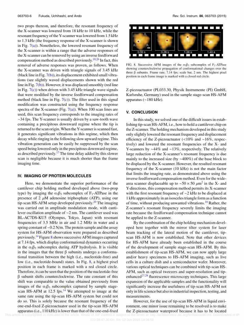
Here, we demonstrate the superior performance of thecantilever chip holding method developed above (two-proptype) by imaging the α3β3 subcomplex of F1-ATPase in thepresence of 2 µM adenosine triphosphate (ATP), using ourtip-scan HS-AFM setup developed previously.20 The imagingwas carried out in amplitude modulation mode, with canti-lever oscillation amplitude of ∼2 nm. The cantilever used wasBL-AC7DS-KU5 (Olympus, Tokyo, Japan) with resonantfrequencies of 3.5 MHz in air and 1.2 MHz in water and aspring constant of∼0.2 N/m. The protein sample and the assaysystem for HS-AFM observation were prepared as describedpreviously.14 Figure 8 shows successive AFM images capturedat 7.14 fps, which display conformational dynamics occurringin the α3β3 subcomplex during ATP hydrolysis. It is visiblein the images that the three β subunits undergo a conforma-tional transition between the high (i.e., nucleotide-free) andlow (i.e., nucleotide-bound) states. In Fig. 8, a highest pixelposition in each frame is marked with a red closed circle.Therefore, it can be seen that the position of the nucleotide-freeβ subunit shifts counterclockwise. The rate constant of thisshift was comparable to the value obtained previously fromimages of the α3β3 subcomplex captured by sample stage-scan HS-AFM at 12.5 fps.14 We attempted to image at thesame rate using the tip-scan HS-AFM system but could notdo so. This is solely because the resonant frequency of theone-end-fixed Z-piezoactuator used in the tip-scan HS-AFMapparatus (i.e., 110 kHz) is lower than that of the one-end-fixed
FIG. 8. Successive AFM images of the α3β3 subcomplex of F1-ATPaseshowing counterclockwise propagation of conformational changes over thethree β subunits. Frame rate, 7.14 fps; scale bar, 2 nm. The highest pixelposition in each frame image is marked with a closed red circle.
Z-piezoactuator (PL033.30, Physik Instrumente (PI) GmbH,Karlsruhe, Germany) used in the sample stage-scan HS-AFMapparatus (∼180 kHz).
V. CONCLUSION
In this study, we solved one of the difficult issues in estab-lishing tip-scan HS-AFM, i.e., how to hold a cantilever chip onthe Z-scanner. The holding mechanism developed in this studyonly slightly lowered the resonant frequency and displacementefficiency of the Z-piezoactuator (<10% and ∼16%, respec-tively) and lowered the resonant frequencies of the X- andY-scanners by ∼44% and ∼13%, respectively. The relativelylarge reduction of the X-scanner’s resonant frequency is duemainly to the increased size (by ∼400%) of the base block tobe displaced by the X-scanner. However, the resulted resonantfrequency of the X-scanner (10 kHz) is not the main factorthat limits the imaging rate, as demonstrated above using theinverse feedforward compensation method. Even for the wide-area scanner displaceable up to ∼50 × 50 µm2 in the X- andY-directions, this compensation method permits its X-scannerwith the first resonant frequency of ∼2 kHz to be displaced at1 kHz approximately in an isosceles triangle form as a functionof time, without producing unwanted vibrations.18 Rather, theZ-scanner’s resonant frequency severely limits the imagingrate because the feedforward compensation technique cannotbe applied to the Z-scanner.
By the combination of the chip holding mechanism devel-oped here together with the mirror tilter system for laserbeam tracking of the lateral motion of the cantilever, tip-scan HS-AFM is now established. Note that other devicesfor HS-AFM have already been established in the courseof the development of sample stage-scan HS-AFM. By thisestablishment of tip-scan HS-AFM, we can now apply largeand/or heavy specimens to HS-AFM imaging, such as livecells in a culture dish and a semiconductor wafer. Moreover,various optical techniques can be combined with tip-scan HS-AFM, such as optical tweezers and super-resolution and tip-enhanced27,28 fluorescence microscopy techniques. This largeexpansion of the applicable samples and the functionality willsignificantly increase the usefulness of tip-scan HS-AFM notonly in life science but also in industrial inspection, testing, andmeasurements.
However, for the use of tip-scan HS-AFM in liquid envi-ronment, one minor issue remaining to be resolved is to makethe Z-piezoactuator waterproof because it has to be located
This article is copyrighted as indicated in the article. Reuse of AIP content is subject to the terms at: http://scitationnew.aip.org/termsconditions. Downloaded to IP:
133.28.47.30 On: Fri, 12 Jun 2015 14:36:55

063703-7 Fukuda, Uchihashi, and Ando Rev. Sci. Instrum. 86, 063703 (2015)
closer to the cantilever chip covered with a liquid than in thecase of sample stage-scan HS-AFM. This is the reason thatwe used the waterproof piezoactuator AE0203D04F (Tokin-NEC, Miyagi, Japan) despite its lower resonant frequencythan the non-waterproof piezoactuator PL033.30 (PI GmbH,Karlsruhe, Germany).
ACKNOWLEDGMENTS
We thank Dr. R. Iino for providing us with the sampleof puried α3β3 subcomplex. This work was supported by theCREST program of the Japan Science and Technology Agency(JST) (to T.A.), the JST program on Development of Systemsand Technology for Advanced Measurement and Analysis (toT.A.), KAKENHI for Basic Research (No. 24227005 to T.A.and Nos. 23115008, 24241048, 26104514, and 26102515 toT.U.), and KAKENHI for Scientific Research on InnovativeAreas: Research in a Proposed Research Area (No. 26119003to T.A.) and Grant-in-Aid for Research Fellows (to S.F.) fromthe Japan Society for the Promotion of Science.
1T. Ando, T. Uchihashi, and T. Fukuda, Prog. Surf. Sci. 83, 337 (2008).2T. E. Schäffer, J. P. Cleveland, F. Ohnesorge, D. A. Walters, and P. K.Hansma, J. Appl. Phys. 80, 3622 (1996).
3T. Ando, N. Kodera, E. Takai, D. Maruyama, K. Saito, and A. Toda, Proc.Natl. Acad. Sci. U. S. A. 98, 12468 (2001).
4G. E. Fantner, G. Schitter, J. H. Kindt, T. Ivanov, K. Ivanova, R. Patel, N.Holten-Andersen, J. Adams, P. J. Thuner, I. W. Rangelow, and P. K. Hansma,Ultramicroscopy 106, 881 (2006).
5T. Ando, T. Uchihashi, N. Kodera, A. Miyagi, R. Nakakita, H. Yamashita,and K. Matada, e-J. Surf. Sci. Nanotechnol. 3, 384 (2005).
6N. Kodera, H. Yamashita, and T. Ando, Rev. Sci. Instrum. 76, 053708(2005).
7T. Fukuma, Y. Okazaki, N. Kodera, T. Uchihashi, and T. Ando, Appl. Phys.Lett. 92, 243119 (2008).
8G. E. Fantner, P. Hegarty, J. H. Kindt, G. Schitter, G. A. G. Cidade, and P.K. Hansma, Rev. Sci. Insturm. 76, 026118 (2005).
9N. Kodera, M. Sakashita, and T. Ando, Rev. Sci. Instrum. 77, 083704 (2006).10Y. K. Yong, S. O. R. Moheimani, B. J. Kenton, and K. K. Leang, Rev. Sci.
Instrum. 83, 121101 (2012).11T. Ando, Nanotechnology 23, 062001 (2012).12M. Shibata, H. Yamashita, T. Uchihashi, H. Kandori, and T. Ando, Nat.
Nanotechnol. 5, 208 (2010).13N. Kodera, D. Yamamoto, R. Ishikawa, and T. Ando, Nature 468, 72 (2010).14T. Uchihashi, R. Iino, T. Ando, and H. Noji, Science 333, 755 (2011).15T. Ando, T. Uchihashi, and N. Kodera, Annu. Rev. Biophys. 42, 393 (2013).16T. Ando, T. Uchihashi, and S. Scheuring, Chem. Rev. 114, 3120 (2014).17C. Braunsmann and T. E. Schäffer, Nanotechnology 21, 225705 (2010).18H. Watanabe, T. Uchihashi, T. Kobashi, M. Shibata, J. Nishiyama, R. Ya-
suda, and T. Ando, Rev. Sci. Instrum. 84, 053702 (2013).19M. Shibata, T. Uchihashi, T. Ando, and R. Yasuda, Sci. Rep. 5, 8724 (2015).20S. Fukuda, T. Uchihashi, R. Iino, Y. Okazaki, M. Yoshida, K. Igarashi, and
T. Ando, Rev. Sci. Instrum. 84, 073706 (2013).21Y. Suzuki, N. Saskai, A. Yoshida, Y. Uekusa, A. Yagi, Y. Imaoka, S. Ito, K.
Karaki, and K. Takeyasu, Sci. Rep. 3, 2131 (2013).22L. Schermelleh, R. Heintzmann, and H. Leonhardt, J. Cell Biol. 190, 165
(2010).23B. Harke, J. V. Chacko, H. Haschke, C. Canale, and A. Diaspro, Opt. Nanosc.
1, 3 (2012).24K. C. Neuman and S. M. Brock, Rev. Sci. Instrum. 75, 2787 (2004).25S. M. R. Akrami, K. Miyata, H. Asakawa, and T. Fukuma, Rev. Sci. Instrum.
85, 126106 (2014).26G. Schitter and A. Stemmer, IEEE Trans. Control Syst. Technol. 12, 449
(2004).27Z. Ma, J. M. Gerton, L. A. Wade, and S. R. Quake, Phys. Rev. Lett. 97,
260801 (2006).28O. J. F. Martin and C. Girard, Appl. Phys. Lett. 70, 705 (1997).
This article is copyrighted as indicated in the article. Reuse of AIP content is subject to the terms at: http://scitationnew.aip.org/termsconditions. Downloaded to IP:
133.28.47.30 On: Fri, 12 Jun 2015 14:36:55