Embed Size (px)
Citation preview
�
����������� ��������������� �� ��������
METHOD STATEMENT FOR HIGH 1.0 DESCRIPTION
When a hammer or drop weight strikes the top of a foundation, a compressive stress wave travels down its shaft at a speed c, which is a function of the elastic modulus E and mass density. The impact induces a force F and a particle velocity v at the top of the foundation. The force is computed by multiplying the measured signals from a pair of strain transducers attached near the top of the pile by the pile area and modules. The velocity measurement is obtained by integrating signals from a pair of accelerometers also attached near the top of the pile. Strain transducers and accelerometers transmit data to a Pile Driving Analyzer® (PDA), for signal processing and results.
As long as the wave travels in one direction, force and velocity are proportional: F = Zv, where: Z = EA/c is the pile impedance E is the pile material modulus of elasticity A is the cross sectional area of the pile c is the material wave speed at which the wave front travels
Soil resistance forces along the shaft and at the toe cause wave reflections that travel and are felt at the top of the foundation. The times at which these reflections arrive at the pile top are related to their location along the shaft. The measured force and velocity near the pile top thus provide necessary and sufficient information to estimate soil resistance and its distribution.
Total soil resistance computed by the PDA includes both static and viscous components. The static resistance can be obtained by subtracting the dynamic component from the total soil resistance. The dynamic component is computed as the product of the pile velocity times a soil parameter called the Damping Factor. The damping factor is an input to the PDA and is related to soil grain size.
The energy delivered to the pile is directly computed as the work done on the pile from the integral of force times incremental displacement ( �Fdu ) which is easily evaluated as force times velocity integrated over time ( �Fvdt ). Maximum compression stresses at the pile top come directly from the measurements. The measurements also allow direct computation of the compression stress at the pile toe and the tension stresses along the shaft. Pile integrity can be evaluated by inspecting the measurements for early tension returns (caused by pile damage) prior to the reflection from the pile
������������ ������������������������� ���
METHOD STATEMENT FOR HIGH-STRAIN DYNAMIC TESTING
When a hammer or drop weight strikes the top of a foundation, a compressive stress wave travels down
which is a function of the elastic modulus E and mass density. The impact induces a force F and a particle velocity v at the top of the foundation. The force is computed by multiplying the measured signals from a pair of
e top of the pile by the pile area and modules. The velocity measurement is obtained by integrating signals from a pair of accelerometers also attached near the top of the pile. Strain transducers and
Pile Driving , for signal processing and results.
As long as the wave travels in one direction, force
modulus of elasticity A is the cross sectional area of the pile c is the material wave speed at which the wave
Soil resistance forces along the shaft and at the toe cause wave reflections that travel and are felt at the
e foundation. The times at which these reflections arrive at the pile top are related to their location along the shaft. The measured force and velocity near the pile top thus provide necessary and sufficient information to estimate soil
Total soil resistance computed by the PDA includes both static and viscous components. The static resistance can be obtained by subtracting the dynamic component from the total soil resistance. The dynamic component is computed as the
t of the pile velocity times a soil parameter called the Damping Factor. The damping factor is an input to the PDA and is related to soil grain size.
The energy delivered to the pile is directly computed as the work done on the pile from the
rce times incremental displacement ( �Fdu ) which is easily evaluated as force times
�Fvdt ). Maximum compression stresses at the pile top come directly from the measurements. The measurements also
f the compression stress at the pile toe and the tension stresses along the shaft. Pile integrity can be evaluated by inspecting the measurements for early tension returns (caused by pile damage) prior to the reflection from the pile
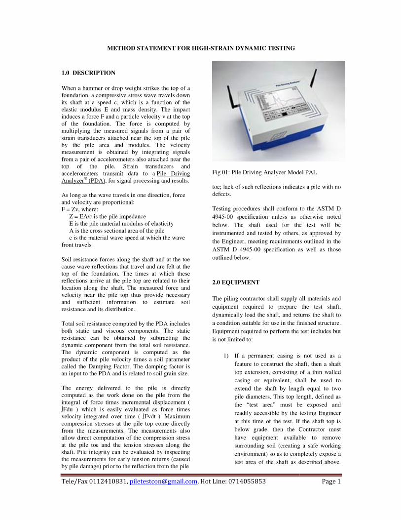
Fig 01: Pile Driving Analyzer Model PAL
toe; lack of such reflections indicates a pile with no defects.
Testing procedures shall conform to the ASTM D 4945-00 specification unless as otherwise noted below. The shaft used for the test will be instrumented and tested by others,the Engineer, meeting requirements outlined in the ASTM D 4945-00 specification as well as those outlined below. 2.0 EQUIPMENT The piling contractor shall supply all materials and equipment required to prepare the test shaft, dynamically load the shaft, and returns the shaft to a condition suitable for use in the finished structure. Equipment required to perform the test includes but is not limited to:
1) If a permanent casing is not used as a feature to construct the shaft, then a shaft top extension, consisting of a thin walled casing or equivalent, shall be used to extend the shaft by length equal to two pile diameters. This top length, defined as the “test area” must be exposed and readily accessible by the testing Engineer at this time of the test. If the shaft top is below grade, then the Contractor must have equipment available to remove surrounding soil (creating a safe working environment) so as to completely expose a test area of the shaft as described above.
� �����
Analyzer Model PAL
toe; lack of such reflections indicates a pile with no
Testing procedures shall conform to the ASTM D 00 specification unless as otherwise noted
below. The shaft used for the test will be instrumented and tested by others, as approved by the Engineer, meeting requirements outlined in the
00 specification as well as those
ontractor shall supply all materials and equipment required to prepare the test shaft,
load the shaft, and returns the shaft to a condition suitable for use in the finished structure. Equipment required to perform the test includes but
If a permanent casing is not used as a feature to construct the shaft, then a shaft top extension, consisting of a thin walled casing or equivalent, shall be used to extend the shaft by length equal to two pile diameters. This top length, defined as the “test area” must be exposed and readily accessible by the testing Engineer
e of the test. If the shaft top is below grade, then the Contractor must have equipment available to remove surrounding soil (creating a safe working environment) so as to completely expose a test area of the shaft as described above.
�
����������� ��������������� ������������������������� ��� �������
Windows on possibly four opposite sides of the shaft may have to be cut off in the steel casing to reach the concrete.
2) Means to insure flat, level, (axial to shaft) and solid concrete shaft top. Concrete should be level with, or above the casing.
3) A drop weight (15ton) in six segments. 4) A guide allowing variable drop heights
typically between 3 and 7 ft (1 to 2 m), or as determined by the Engineer based on WEAP analysis.
5) A shaft top cushion consisting of new sheets of plywood with total thickness between 2 to 6 inches (50 to 150 mm), or as determined by the Engineer.
6) A steel striker plate with a thickness of at least 2 inches (50 mm) and an area between 70 to 90% of shaft top area but not less than the area of the impacting surface of the drop weight to be placed on top of the plywood cushion.
7) If protruding reinforcing bars are present, the Contractor has the option to incorporate the reinforcing steel in the test area. Upon successful completion of the dynamic test, the surrounding concrete can then be removed as to make the pile suitable for use in the structure. If the Contractor selects not to incorporate the steel in such a manner as described above, then a steel beam or pipe (cross sectional area approximately 20% of the shaft cross sectional area) shall be supplied with sufficient length such that the ram impact will not interfere with the reinforcing bars. Steel striker plates and plywood cushion must also be sized so that they cover as much of the impact area as possible.
8) One (1) kW of 115 Volt AC power. 9) Surveyors' transit, laser light, or equivalent
for measurements of pile set under each impact.
3.0 DYNAMIC TESTING FIRM The actual test shall be conducted and/or supervised by a charted professional Engineer with at least two (2) years of dynamic testing or who has achieved Basic Level or better on the Foundation
Qa Examination for Providers of PDA Testing Services. The dynamic testing firm will supply the following testing instrumentation in addition to that outlined in ASTM specification D 4945-00 Section 5:
1) Pile Driving Analyzer (PDA) manufactured by Pile Dynamics, Inc., model PAK or PAL.
2) Two calibrated strain transducers. 3) Two calibrated accelerometers.
Prior to performing the dynamic test, the testing Engineer must be provided with soil borings, shaft installation records, concrete properties (strength, etc.) and details regarding the anticipated dynamic loading equipment. The test Engineer is required to perform wave equation analyses (using GRLWEAP or equivalent) to determine the suitability of the proposed dynamic loading equipment and an acceptable range of ram drop heights so as not to cause damage in the shaft during the test. 4.0 PROCEDURE 4.1
1) The test shaft shall be constructed using the approved installation techniques.
2) If a permanent casing is not required, then the upper length equal to two shaft diameters, noted as the "test area", must be cased in a thin wall tube or equivalent as noted above. Casing of this test area must be made as a continuation of the construction of the shaft. There should not be soil contamination or non-uniformities in the concrete located within or below the test area. Shaft top shall be made level to the casing and smoothed.
3) Prior to testing time, the Contractor shall make the shaft test area length completely accessible to the testing Engineer.
4.2
1) Prior to the test four "windows" (approximate size of 6 by 6 inches (150 by 150 mm) diametrically opposite of each other will be located and removed from the casing if appropriate.
2) In cases where casing is not present, the testing shall smooth (by grinding) areas
�
����������� ��������������� ������������������������� ��� �������
around the pile circumference such that proper gage attachment can be accomplished.
3) Gages shall be attached by the testing Engineer to the exposed concrete or steel casing in a secure manner as to prevent slippage under impact.
4) Shaft top should be examined to insure concrete is flush with or above the casing.
5) Apply plywood cushion and then striker plate to the shaft top. If reinforcing protrudes from the shaft top, then the steel beam or pipe (used to transfer the impact to the shaft top) should be secured in such a manner as not to move under impact.
6) At least two (2) hammer impacts should be applied to the pile top. First drop height should be minimal to allow the testing Engineer to assess the testing equipment, the driving system and pile stresses. Subsequent impacts can then be applied by utilizing higher drop heights.
7) Upon completion of the test, it is the Contractors' responsibility to return the pile to acceptable production condition.
5.0 REPORTING OF RESULTS (Report Format) The report will be submitted within three working days. In addition to the field results, results from at least one (1) CAPWAP analysis (CASE Pile Wave
Analysis Program) shall be submitted. CAPWAP analyses shall be performed by a charted engineer who has experience more than ten year in the same field. The report must also provide the following:
1) Pile Details 2) Hammer Details. 3) Field Results. 4) Measured Velocity and Forces Graph 5) CAPWAP analysis results with Dynamic
parameters. 6) For each impact the maximum measured
force, maximum calculated tension force, transferred energy to the gage location, corresponding stresses, and the Case Method bearing capacity.
7) Assessment of the test results both with respect to pile capacity and integrity.
6.0 Safety Measures
All staff involved with the testing work shall be included in the safety, health and environmental issues associated with the works. Only trained personnel with relevant experience shall be allowed to handle machinery. Appropriate safety signboard, barriers and lighting shall be and other safeguards shall be provided. All operations shall be carried out in accordance with the safety requirement. All field personnel will use safety shoes helmets, cover all, goggles and dust mask etc as required
������������������ �������� ������������� ����������
����������������
�����������
������� ����� !�"��#�$�
��
%& �'��� � (�)��* �& �+)�&
�
����������� ��������������� ������������������������� ��� �������
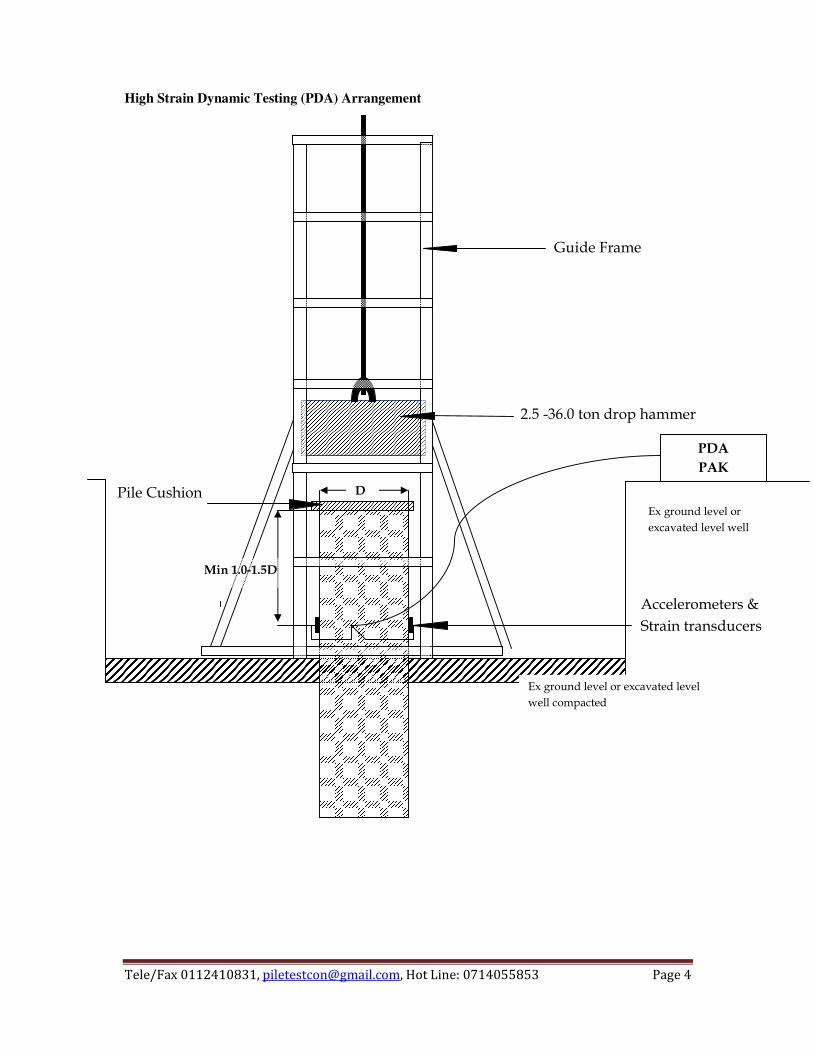
High Strain Dynamic Testing (PDA) Arrangement
����������
�� ��������������������
�������������
����
����
�
� �
����������������
�����������������
��
� ����� ��
� �!��������"������� �"������"���
#������������
� �!��������"������
� �"������"���#����
��������
�
����������� ��������������� ������������������������� ��� �������
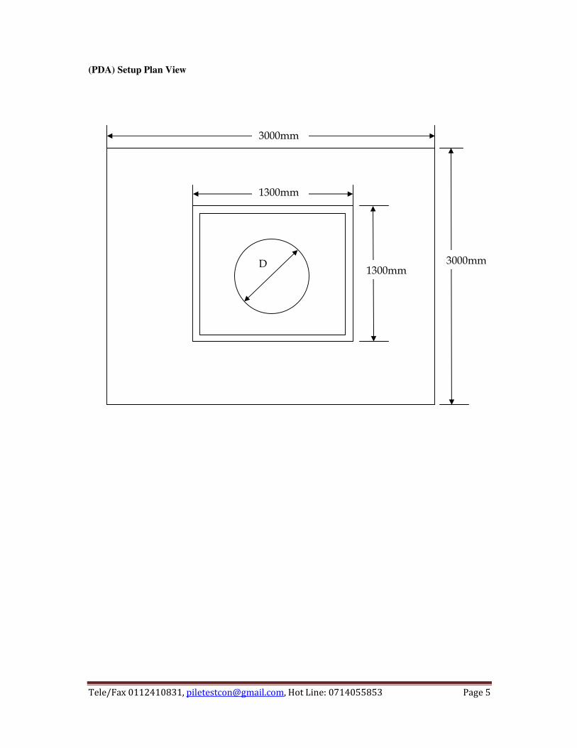
(PDA) Setup Plan View
�����
�����
$����
$����
%�
�
����������� ��������������� ������������������������� ��� ����!��
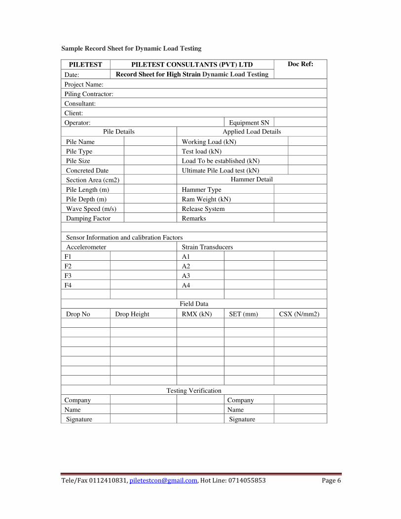
Sample Record Sheet for Dynamic Load Testing
PILETEST PILETEST CONSULTANTS (PVT) LTD Doc Ref: Date: Record Sheet for High Strain Dynamic Load Testing Project Name: Piling Contractor: Consultant: Client: Operator: Equipment SN
Pile Details Applied Load Details
Pile Name Working Load (kN) Pile Type Test load (kN) Pile Size Load To be established (kN) Concreted Date Ultimate Pile Load test (kN) Section Area (cm2) Hammer Detail
Pile Length (m) Hammer Type Pile Depth (m) Ram Weight (kN) Wave Speed (m/s) Release System Damping Factor Remarks Sensor Information and calibration Factors Accelerometer Strain Transducers F1 A1 F2 A2 F3 A3 F4 A4
Field Data
Drop No Drop Height RMX (kN) SET (mm) CSX (N/mm2)
Testing Verification Company Company Name Name Signature Signature


![PET User Manual - Piletest · 2017-08-17 · PET software is installed to [Start]-[Programs]-[Pile Testing]-[PET] 4. PET program files are installed to \Program Files\Piletest.com](https://img.pdfslide.net/doc/110x75/5f8dce0737f86b4162585dcd/pet-user-manual-piletest-2017-08-17-pet-software-is-installed-to-start-programs-pile.jpg)

![[XLS]research.engr.oregonstate.eduresearch.engr.oregonstate.edu/usucger/Books/ISC-3 PAPERS... · Web viewPile dynamic testing, PDA, CAPWAP, Wave equation analysis, Bearing capacity](https://img.pdfslide.net/doc/110x75/5ad41dec7f8b9a0d2d8bf41d/xls-papersweb-viewpile-dynamic-testing-pda-capwap-wave-equation-analysis.jpg)