Embed Size (px)
Citation preview
METHODOLOGY FOR IMPROVED
EFFICIENCY OF FLEET VEHICLES AND
COMBUSTION ENGINES
Revision of CDM Methodology AMS-III.BC.
Prepared by dynaCERT
Title Methodology for Improved Efficiency of Fleet Vehicles and Combustion Engines
Version 3.0
(based on CDM methodology “AMS-III.BC.: Emission reductions through
improved efficiency of vehicle fleets”, version 2.0)
Date of Issue 08 October 2021
Type Methodology revision
Sectoral Scope 3. Energy Demand, 7. Transport
Prepared By dynaCERT
Contact 101-501 Alliance Avenue Toronto ON Canada M6N 2J1
Robert Maier, [email protected]
Methodology: VCS Version 4.0
Relationship to Approved or Pending
Methodologies
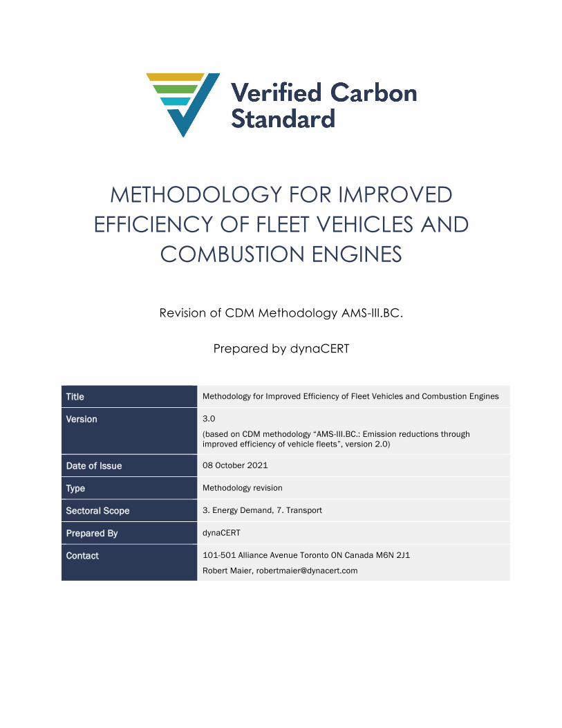
Approved and pending methodologies under the VCS Program and approved GHG programs that fall
under the same combination of sectoral scopes, were reviewed to determine whether an existing
methodology could be reasonably revised to meet the objective of this proposed methodology. 13
methodologies were identified and are set out in Table 1.
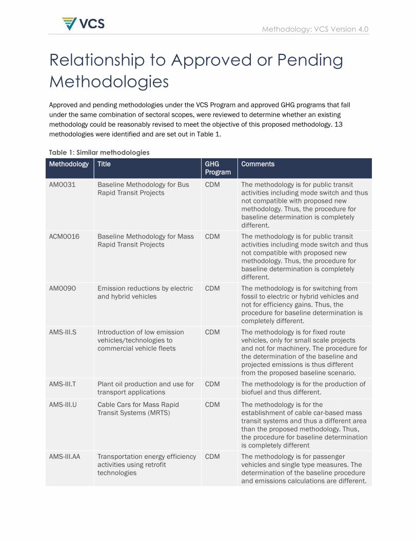
Table 1: Similar methodologies
Methodology Title GHG
Program
Comments
AM0031 Baseline Methodology for Bus
Rapid Transit Projects
CDM The methodology is for public transit
activities including mode switch and thus
not compatible with proposed new
methodology. Thus, the procedure for
baseline determination is completely
different.
ACM0016 Baseline Methodology for Mass
Rapid Transit Projects
CDM The methodology is for public transit
activities including mode switch and thus
not compatible with proposed new
methodology. Thus, the procedure for
baseline determination is completely
different.
AM0090 Emission reductions by electric
and hybrid vehicles
CDM The methodology is for switching from
fossil to electric or hybrid vehicles and
not for efficiency gains. Thus, the
procedure for baseline determination is
completely different.
AMS-III.S Introduction of low emission
vehicles/technologies to
commercial vehicle fleets
CDM The methodology is for fixed route
vehicles, only for small scale projects
and not for machinery. The procedure for
the determination of the baseline and
projected emissions is thus different
from the proposed baseline scenario.
AMS-III.T Plant oil production and use for
transport applications
CDM The methodology is for the production of
biofuel and thus different.
AMS-III.U Cable Cars for Mass Rapid
Transit Systems (MRTS)
CDM The methodology is for the
establishment of cable car-based mass
transit systems and thus a different area
than the proposed methodology. Thus,
the procedure for baseline determination
is completely different
AMS-III.AA Transportation energy efficiency
activities using retrofit
technologies
CDM The methodology is for passenger
vehicles and single type measures. The
determination of the baseline procedure
and emissions calculations are different.
Methodology: VCS Version 4.0
AMS-III.AP Transport energy efficiency
activities using post-fit idling
stop device
CDM The methodology is for use in one type of
device and for passenger transport.
AMS-III.AQ Introduction of Bio-CNG in
transportation applications
CDM The methodology is for the introduction
of Bio-CNG in transportation applications
and thus a different area from this
methodology.
AMS-III.BC Emissions reductions through
improved efficiency of vehicle
fleets
CDM This methodology is the basis of the
current methodology but does not
include the revision to include
technology improvements that improve
combustion efficiency in engines with
out improving efficiency of engines and
does not include mobile machinery.
AMS-III.AT Transport energy efficiency
activities installing digital
tachograph systems to
commercial freight transport
fleets
CDM The methodology is applicable to one
type of device only. The baseline
determination is different.
VM0019 Fuel switch from gasoline to
ethanol in flex-fuel vehicles.
VCS This methodology calculates the GHG
emissions reductions from substituting
ethanol in place of gasoline or gasoline
blends in commercial fleets of flex-fuel
vehicles. The proposed methodology
does not include ethanol fuel switch.
VMR0004 Revision to AMS-III.BC to include
Mobile Machinery v1.03
VCS The methodology is for project activities
that improve the efficiency of vehicle
fleets resulting in reduced fuel usage
and greenhouse gas emissions.
This revision is to include mobile
machinery but does not incorporate
revisions proposed in the proposed
methodology.
Methodology: VCS Version 4.0
CONTENTS
1 SOURCES .............................................................................................................. 5
2 SUMMARY DESCRIPTION OF THE METHODOLOGY ............................................ 5
3 DEFINITIONS ......................................................................................................... 5
4 APPLICABILITY CONDITIONS .............................................................................. 6
5 PROJECT BOUNDARY .......................................................................................... 9
6 BASELINE SCENARIO ......................................................................................... 10
7 ADDITIONALITY .................................................................................................. 10
8 QUANTIFICATION OF GHG EMISSION REDUCTIONS AND REMOVALS .......... 11
8.1 Baseline Emissions ............................................................................................................. 11
8.2 Project Emissions ............................................................................................................... 17
8.3 Leakage ............................................................................................................................. 19
8.4 Net GHG Emission Reductions and Removals .............................................................. 19
9 MONITORING .................................................................................................... 20
9.1 Data and Parameters Available at Validation ............................................................ 20
9.2 Data and Parameters Monitored ................................................................................... 20
9.3 Description of the Monitoring Plan ................................................................................. 26
10 REFERENCES ....................................................................................................... 26
1 SOURCES
This methodology is based on AMS-III.BC.: Emission reductions through improved efficiency of
vehicle fleets (version 2.0) and VMR0004 Revision to AMS-III.BC to include Mobile Machinery
(version 1.03).
2 SUMMARY DESCRIPTION OF THE
METHODOLOGY
Additionality and Crediting Method
Additionality Project Method
Crediting Baseline Project Method
This methodology applies to project activities that improve efficiency of vehicle fleets and
mobile machinery (e.g. fleets of trucks, buses, cars, taxis or motorized tricycles, excavators,
cranes), resulting in reduced fuel usage and GHG emissions. This methodology is globally
applicable. It is not applicable to fuel switch activities and measures that improve the system
efficiency of the fleet such as changes of operational procedures.
The methodology is based on the CDM methodology AMS-III.BC. Emission reductions through
improved efficiency of vehicle fleets and approved VCS Methodology Revision VMR0004 that
included mobile machinery.
This methodology includes these further revisions:
• Inclusion of activities that improve combustion efficiency; and
• Inclusion of a telematics system for monitoring fuel usage, odometer distance and
operational time of the engine, to record changes in engine performance in real time.
3 DEFINITIONS
Activity level
The index used to determine the output level of the vehicle/machinery (e.g., machine hour or
gross ton-hour of the machine).
Gross vehicle weight (GVW)
Equals vehicle weight plus freight weight, measured in tons.
Methodology: VCS Version 4.0
6
Heavy duty vehicles
Vehicles with gross vehicle weight more than or equal to 3.5 t are classified as heavy-duty
vehicles.
Light duty vehicles
Vehicles with gross vehicle weight less than 3.5 t are classified as light duty vehicles.
Mobile machinery
Equipment which is not fixed at a specific site but can be moved around either under its own
power or with assistance when engineering specifications or logistics dictate (e.g., moving a
loader using a lo-bed rather than driving the loader to the destination). Mobile machinery must be
self-propelled, except where a self-propelled unit has had its drive carriage removed to secure the
unit to a structure during operation and may include but not be limited to: excavators, log
harvesting bunchers, log loaders, cranes, timber processors, fork-lifters, road-building machines
and/or bulldozers. Generators used for power generation do not qualify as mobile machinery
under this methodology.
Telematics System
Telematics is a method of monitoring cars, trucks, equipment and other assets by using GPS
technology and on-board diagnostics (OBD) to plot the asset's movements on a computerized
map. By connecting to the on-board diagnostics, telematics devices retrieve data generated by
the vehicle, like GPS position, speed, fuel usage, engine light information and faults.
Tons (t)
Metric tons
4 APPLICABILITY CONDITIONS
This methodology applies to project activities that improve efficiency of vehicle fleets and
mobile machinery (e.g. fleets of trucks, buses, cars, taxis or motorized tricycles, excavators,
cranes), resulting in reduced fuel usage and GHG emissions.
This methodology is applicable under the following conditions:
1) This methodology applies to project activities that implement one or more of the following
measures:
Methodology: VCS Version 4.0
7
a) Idling stop device,1
b) Eco-drive systems;2
c) Tire-rolling resistance improvements;3
d) Air-conditioning system improvements;4
e) Use of low viscosity oils;5
f) Aerodynamic drag reduction measures;6
g) Transmission improvements;7
h) Retrofits that improve engine and combustion efficiency.8
i) Other energy efficiency improvement measures identified by the project description.
Such other measures must have been described in independent third-party studies as
leading to fuel savings.
2) More than one energy efficiency measure covered by the methodology may be
implemented in the project vehicle fleet(s) and the measures implemented may vary across
vehicles in the fleet(s).
3) Where the project proponent is not the owner of the vehicle fleets (eg, the project
proponent is a fleet manager with many clients, each client being the owner of its
1 Refers to the action of turning off the vehicle engine and thus preventing idling (as specifically defined above) and the associated fuel
consumption that would otherwise have occurred while idling, in absence of the project activity. Anti -idling devices can also include
techniques to avoid use of the base engine during extended idle by substituting alternative sources of HVAC (heating, ventila tion or air
conditioning) and electricity during rest stops.
2 Eco-drive systems include equipment that monitors vehicle and driver performance and provides real- time feedback to drivers on
efficient driving behavior.
3 Rolling resistance can be reduced by avoiding under-inflation of existing tyres e.g., through automatic tire inflation (ATI), usage of
special low rolling resistance tyres, or substituting one wide tyre for a pair of dual tyres on trucks.
4 Enhanced air conditioning systems can decrease base engine load requirements from mobile air conditioning systems by replacing
fixed displacement compressors (FDCs) with externally controlled variable displacement compressors (VDCs), using improved control
systems, condensers and evaporators.
5 Low-viscosity engine lubricants are made from synthetic or mineral oil blends for the purpose of reducing internal engine fr iction. Low
viscosity oils based on SAE-Viscosity classes are 0W30 and 5W30.
6 Aerodynamic drag of trucks can be significantly reduced by installing add-on devices to improve the vehicle profile (truck tractor
aerodynamic drag reduction options include cab top deflector, sloping hood, and cab side flares; truck side and underside
aerodynamic drag reduction options include closing and covering the gap between a tractor and trailer (or van), aerodynamic b umper,
underside air baffles, and wheel well covers), pneumatic blowing systems (this type of system blows air from slots at the rear of the
trailers of heavy-duty vehicles in order to smooth air flow over the trailer surfaces and reduce aerodynamic drag, and boat tail plates
rectangular plates mounted to the end of a trailer in an attempt to reduce the wake of trucks), or by improving vehicle load profile.
7 Improving transmission systems by using high-efficiency transmission technologies i.e., continuously variable transmission (CVT)
and/or low-viscosity transmission lubricants.
8 Retrofits involves direct installation of technologies onto the vehicle/engine that improve the efficiency of engine operatio n and fuel
combustion by, for example, tapping into spare unused kinetic energy, solar energy or thermo- electric generation and/or generating
hydrogen on board though an electrolysis technology, e.g., electro-catalytic efficiency technologies.
Methodology: VCS Version 4.0
8
respective vehicle fleets), there must exist a contract between the project proponent and
each fleet owner to establish clear ownership of the emission reductions.9
4) The project proponent must provide ex-ante estimation of the percentage of baseline
emissions avoided per each energy efficiency measure. The ex-ante estimations must be
based on published literature, official reports or statistics published by an independent
third party or studies carried out by the project proponent, and validated by the
validation/verification body. This is applied for any measure identified in the project
description. The ex-ante estimations will also serve as a cap on the specific emission
reductions (using the specific emission reduction percentage per activity unit as the
metric10). In other words, the reduction in the project emission factor compared to the
baseline emission factor may not exceed the ex-ante estimation.
5) This methodology is not applicable under the following conditions:
a) Measures that improve the system efficiency of the fleet, for example a change of
operational procedures to improve the occupancy rate of vehicles and modal shift in
transportation.
b) A switch from fossil fuels to biofuels in transportation applications. The usage of a fixed
biofuel blend is, however, admissible if project vehicles use the same blend of biofuel
as used by baseline vehicles. In the case of using biofuel blends, the biofuel share is
accounted for as zero emitting.
c) A fuel-switch, for example from liquid to gaseous fuels.
6) Project fleets may use various fuel types. The composition of the fleet with regard to fuel
types used may also change over time. The introduction of hybrid vehicles is allowed. Hybrid
fuel vehicles are classified according to their fossil fuel engine type and compared with the
same baseline fossil fuel type (e.g., compressed natural gas, diesel, gasoline hybrids are
compared with diesel, gasoline or compressed natural gas engines).
7) Only vehicles in which at least one of the ex-ante identified project activity measures has
been implemented shall be included in the project fleet.
8) Each fleet included in the project activity shall include only one vehicle category. In each
vehicle category, vehicles are classified according to the fuel types used. Baseline and
project emissions are calculated for each fuel type of each vehicle category. A project
9 This applicability condition is not a substitute for the VCS requirements with respect to Right of Use. The project description must be
accompanied by documentary evidence establishing Right of Use, in accordance with the VCS rules.
10 In other words, it is the percentage of emission reductions that is relevant for consideration. Therefore, the cap is defined based on
the specific emission reductions arising from each energy efficiency measure. For example, assume idling stop and eco-drive were
estimated to reduce CO2 emissions by 10% per machine hour. Also, ex ante 5,000 machine hours were projected for the vehicle type,
with specific emissions per machine hour of 2 tCO2 per hour. The specific cap on emission reductions would therefore be 0.2 tCO2 per
machine hour (i.e,, 10% of 2 tCO2). This is independent of the activity level. The absolute cap will thereafter be the specific cap
multiplied with the activity level. If in year y, for example, there were 6,000 machine hours of operation (as opposed to 5,000), the cap
would be 6,000 x 0.2 = 1,200 tCO2. See applicability condition 5 of CDM methodology AMS-III.BC which states that the cap is based on
the specific emission reduction (per tkm or per km) and not based on absolute figures.
Methodology: VCS Version 4.0
9
activity may, however, encompass various fleets. Vehicle categories in the context of this
methodology are
a) Trucks with a gross vehicle weight11 (GVW) >3.5 t;
b) Trucks with a GVW <3.5 t;
c) Buses with a GVW >3.5 t;
d) Taxis: in the case of significantly different taxi types such as conventional cars,
minibuses, jeepneys, etc., these shall also be considered as separate vehicle
categories;
e) Passenger cars (e.g., company cars, rental cars);
f) Motorized tricycles (e.g., used as taxis or for deliveries); and
g) Mobile machinery.
5 PROJECT BOUNDARY
The project boundary is the physical, geographical location of the vehicles that are part of the
project activity. The spatial extent of the project boundary encompasses the geographical area
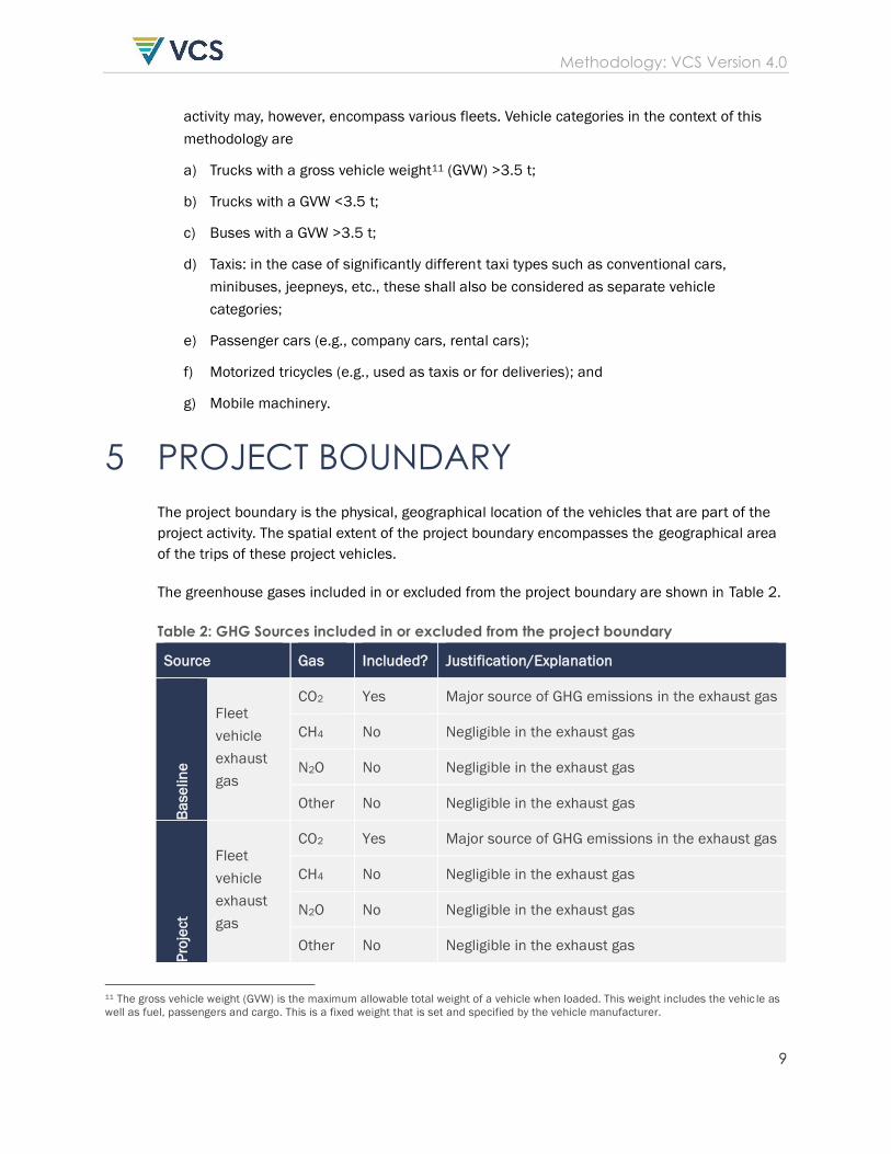
of the trips of these project vehicles. The greenhouse gases included in or excluded from the project boundary are shown in Table 2.
Table 2: GHG Sources included in or excluded from the project boundary
Source Gas Included? Justification/Explanation
Ba
se
lin
e
Fleet
vehicle
exhaust
gas
CO2 Yes Major source of GHG emissions in the exhaust gas
CH4 No Negligible in the exhaust gas
N2O No Negligible in the exhaust gas
Other No Negligible in the exhaust gas
Pro
ject
Fleet
vehicle
exhaust
gas
CO2 Yes Major source of GHG emissions in the exhaust gas
CH4 No Negligible in the exhaust gas
N2O No Negligible in the exhaust gas
Other No Negligible in the exhaust gas
11 The gross vehicle weight (GVW) is the maximum allowable total weight of a vehicle when loaded. This weight includes the vehic le as
well as fuel, passengers and cargo. This is a fixed weight that is set and specified by the vehicle manufacturer.
Methodology: VCS Version 4.0
10
6 BASELINE SCENARIO
The baseline scenario is the operation of a group of vehicles of the same fleet or mobile
machinery without energy efficiency measures and for similar transportation services as the
project vehicles.
7 ADDITIONALITY
Step 1: Regulatory Surplus The project shall not be mandated by any law, statute or other regulatory framework, or for
UNFCCC non-Annex I countries, any systematically enforced law, statute or other regulatory
framework. For UNFCCC non-Annex I countries, laws, statutes, regulatory frameworks or policies
implemented12 since 11 November 2001 that give comparative advantage to less emissions-
intensive technologies or activities relative to more emissions-intensive technologies or
activities need not be taken into account. For all countries, laws, statutes, regulatory
frameworks or policies implemented since 11 December 1997 that give comparative advantage
to more emissions-intensive technologies or activities relative to less emissions-intensive
technologies or activities shall not be taken into account.
Step 2: Implementation barriers
Additionality may be demonstrated based on typical barriers faced by energy efficiency projects,
including:
(a) Commercial/legal barriers: the “owner/tenant” contractual issue typical of energy
efficiency projects may be a legitimate barrier. This is typical for example in the case of
the fleets of car rental companies where the car renter buys the fuel and the owner
makes the vehicle investment. Many taxi fleets especially in developing countries are
also managed in this manner, with taxi drivers paying a fixed daily rent per vehicle. The
same is true in the case of leased vehicles typical in the trucking business.
(b) Aggregation barriers: in order to make implementation of efficiency projects feasible,
they may require an aggregation mechanism. Aggregation mechanisms, in the case of
promoting efficiency in transport fleets, have been successful for example in
Switzerland, Canada and the United States. Aggregation parties are generally business
associations, efficiency-driven institutions, or providers of technology solutions for
efficiency improvements. The cost of establishing and maintaining such an aggregation
mechanism can, however, be a major barrier that can be offset with carbon revenues.
12 Implemented in the context of this paragraph means enacted or introduced, consistent with use of the term under the CDM rules on
so-called Type E+ and Type E- policies.
Methodology: VCS Version 4.0
11
(c) Other barriers: in case other barriers exist, these may be assessed based on the most
recent version of the CDM additionality tool.
All barriers shall be assessed based on the CDM Guidelines for objective demonstration and
assessment of barriers.
Step 3: Common practice
Fleet owners are often skeptical of such practices and resistant to adopt them. A project
activity is considered to be additional if the market penetration rate of each of the planned
project measures is less than 5 per cent for the types of vehicles included in the fleets.13
Sources of data for the market penetration rates may include independent studies, information
from business associations, analysis of publicly available information demonstrating the
“penetration rate” of the measures proposed by the project within the host country, sample
surveys of comparable fleets that ask fleet managers to identify vehicles in which the identified
efficiency measures have been implemented in the absence of the VCS or any other approved
GHG programs, or random sample surveys of the same vehicle categories, carried out, for
example, at bus/truck/taxi depots in major cities.
8 QUANTIFICATION OF GHG EMISSION
REDUCTIONS AND REMOVALS
8.1 Baseline Emissions
The baseline scenario is the operation of a group of vehicles of the same fleet without energy
efficiency measures and for similar transportation services as the project vehicles. Baseline
emissions are calculated based on a baseline emission factor for each vehicle category i and
fuel type x (BEFkm,I,x,y) derived from:
• The vehicles own data prior to the project measure’s implementation, for all vehicle types
equipped with a telematics system capable of tracking fuel consumption; or,
• The monitored specific fuel consumption of a control group of vehicles and the monitored
project activity level, for all vehicle types not equipped with a telematics system capable of
tracking fuel consumption.
13 Penetration rates are assessed for the specific categories of vehicles in which the measures are implemented, and not for the fleet
as a whole, because a project may implement specific measures only on some vehicles and not the entire fleet. To assess the
penetration rate for the fleet, a weighting based on the number of each type of vehicle is made. Each planned measure must fulfil the
threshold value of 5 per cent individually if this barrier is used.
Methodology: VCS Version 4.0
12
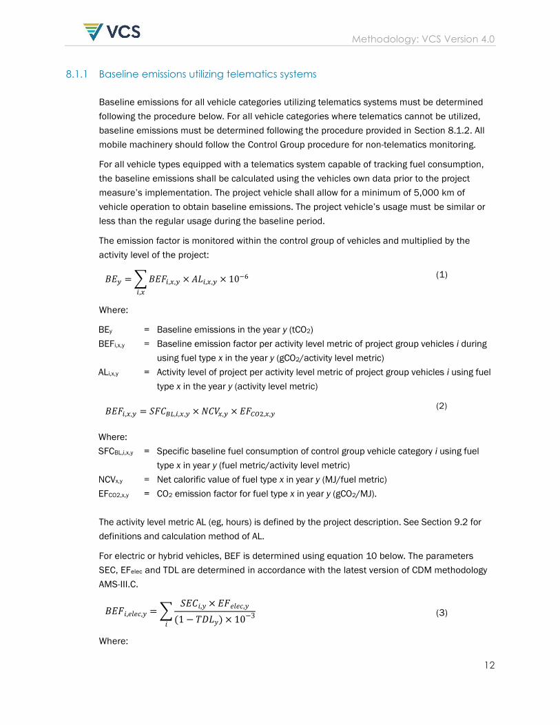
8.1.1 Baseline emissions utilizing telematics systems
Baseline emissions for all vehicle categories utilizing telematics systems must be determined
following the procedure below. For all vehicle categories where telematics cannot be utilized,
baseline emissions must be determined following the procedure provided in Section 8.1.2. All
mobile machinery should follow the Control Group procedure for non-telematics monitoring.
For all vehicle types equipped with a telematics system capable of tracking fuel consumption,
the baseline emissions shall be calculated using the vehicles own data prior to the project
measure’s implementation. The project vehicle shall allow for a minimum of 5,000 km of
vehicle operation to obtain baseline emissions. The project vehicle’s usage must be similar or
less than the regular usage during the baseline period.
The emission factor is monitored within the control group of vehicles and multiplied by the
activity level of the project:
𝐵𝐸𝑦 = ∑ 𝐵𝐸𝐹𝑖,𝑥,𝑦 × 𝐴𝐿𝑖,𝑥,𝑦 × 10−6
𝑖,𝑥
(1)
Where:
BEy = Baseline emissions in the year y (tCO2)
BEFi,x,y = Baseline emission factor per activity level metric of project group vehicles i during
using fuel type x in the year y (gCO2/activity level metric)
ALi,x,y = Activity level of project per activity level metric of project group vehicles i using fuel
type x in the year y (activity level metric)
𝐵𝐸𝐹𝑖,𝑥,𝑦 = 𝑆𝐹𝐶𝐵𝐿,𝑖,𝑥,𝑦 × 𝑁𝐶𝑉𝑥,𝑦 × 𝐸𝐹𝐶𝑂2,𝑥,𝑦 (2)
Where:
SFCBL,i,x,y = Specific baseline fuel consumption of control group vehicle category i using fuel
type x in year y (fuel metric/activity level metric)
NCVx,y = Net calorific value of fuel type x in year y (MJ/fuel metric)
EFCO2,x,y = CO2 emission factor for fuel type x in year y (gCO2/MJ).
The activity level metric AL (eg, hours) is defined by the project description. See Section 9.2 for
definitions and calculation method of AL.
For electric or hybrid vehicles, BEF is determined using equation 10 below. The parameters
SEC, EFelec and TDL are determined in accordance with the latest version of CDM methodology
AMS-III.C.
𝐵𝐸𝐹𝑖,𝑒𝑙𝑒𝑐,𝑦 = ∑𝑆𝐸𝐶𝑖,𝑦 × 𝐸𝐹𝑒𝑙𝑒𝑐,𝑦
(1 − 𝑇𝐷𝐿𝑦) × 10−3𝑖
(3)
Where:
Methodology: VCS Version 4.0
13
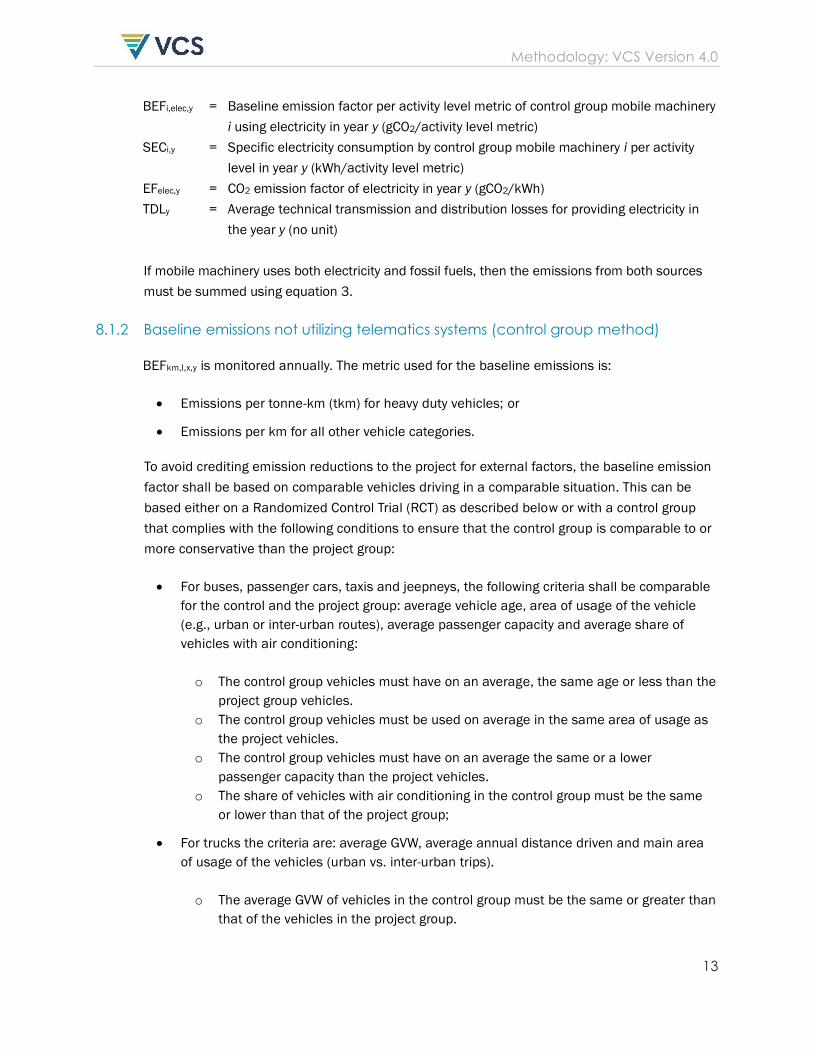
BEFi,elec,y = Baseline emission factor per activity level metric of control group mobile machinery
i using electricity in year y (gCO2/activity level metric)
SECi,y = Specific electricity consumption by control group mobile machinery i per activity
level in year y (kWh/activity level metric)
EFelec,y = CO2 emission factor of electricity in year y (gCO2/kWh)
TDLy = Average technical transmission and distribution losses for providing electricity in
the year y (no unit)
If mobile machinery uses both electricity and fossil fuels, then the emissions from both sources
must be summed using equation 3.
8.1.2 Baseline emissions not utilizing telematics systems (control group method)
BEFkm,I,x,y is monitored annually. The metric used for the baseline emissions is:
• Emissions per tonne-km (tkm) for heavy duty vehicles; or
• Emissions per km for all other vehicle categories.
To avoid crediting emission reductions to the project for external factors, the baseline emission
factor shall be based on comparable vehicles driving in a comparable situation. This can be
based either on a Randomized Control Trial (RCT) as described below or with a control group
that complies with the following conditions to ensure that the control group is comparable to or
more conservative than the project group:
• For buses, passenger cars, taxis and jeepneys, the following criteria shall be comparable
for the control and the project group: average vehicle age, area of usage of the vehicle
(e.g., urban or inter-urban routes), average passenger capacity and average share of
vehicles with air conditioning:
o The control group vehicles must have on an average, the same age or less than the
project group vehicles.
o The control group vehicles must be used on average in the same area of usage as
the project vehicles.
o The control group vehicles must have on an average the same or a lower
passenger capacity than the project vehicles.
o The share of vehicles with air conditioning in the control group must be the same
or lower than that of the project group;
• For trucks the criteria are: average GVW, average annual distance driven and main area
of usage of the vehicles (urban vs. inter-urban trips).
o The average GVW of vehicles in the control group must be the same or greater than
that of the vehicles in the project group.
Methodology: VCS Version 4.0
14
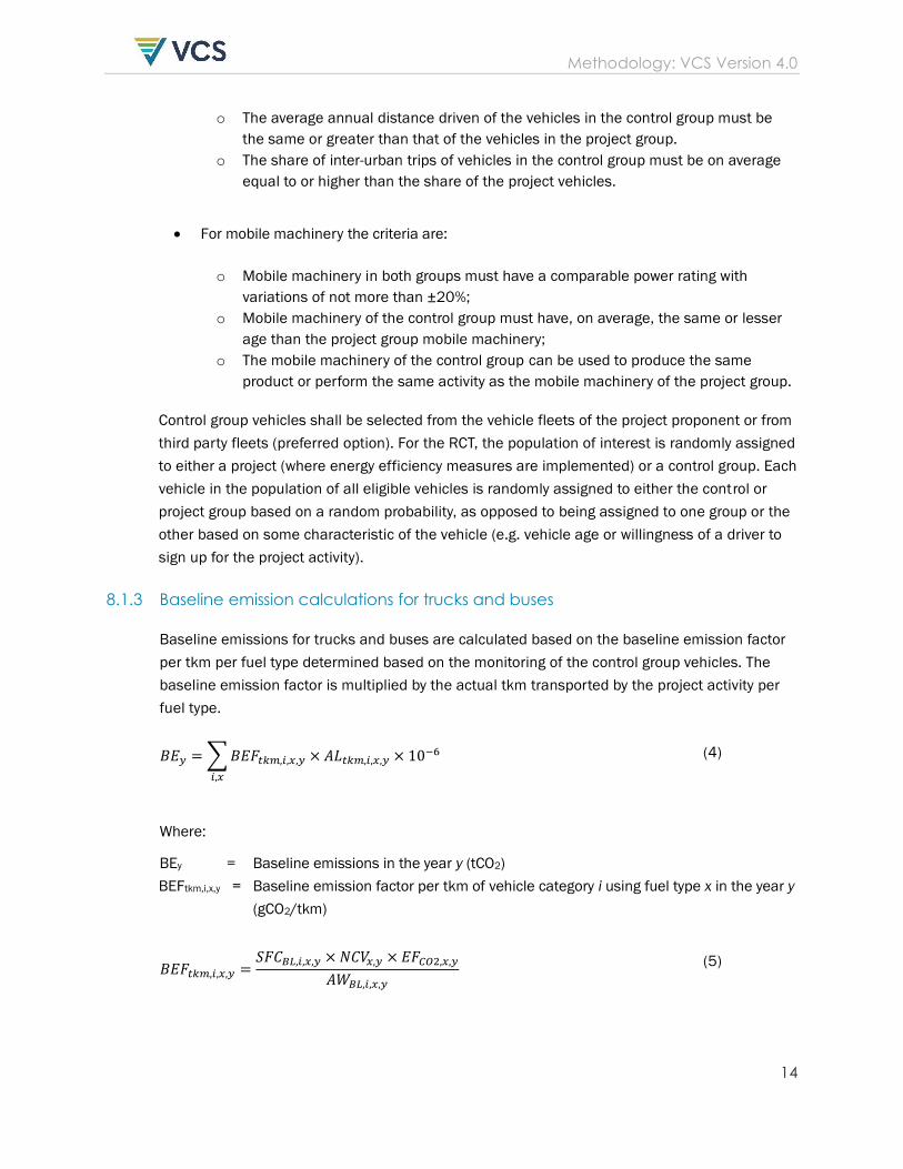
o The average annual distance driven of the vehicles in the control group must be
the same or greater than that of the vehicles in the project group.
o The share of inter-urban trips of vehicles in the control group must be on average
equal to or higher than the share of the project vehicles.
• For mobile machinery the criteria are:
o Mobile machinery in both groups must have a comparable power rating with
variations of not more than ±20%;
o Mobile machinery of the control group must have, on average, the same or lesser
age than the project group mobile machinery;
o The mobile machinery of the control group can be used to produce the same
product or perform the same activity as the mobile machinery of the project group.
Control group vehicles shall be selected from the vehicle fleets of the project proponent or from
third party fleets (preferred option). For the RCT, the population of interest is randomly assigned
to either a project (where energy efficiency measures are implemented) or a control group. Each
vehicle in the population of all eligible vehicles is randomly assigned to either the control or
project group based on a random probability, as opposed to being assigned to one group or the
other based on some characteristic of the vehicle (e.g. vehicle age or willingness of a driver to
sign up for the project activity).
8.1.3 Baseline emission calculations for trucks and buses
Baseline emissions for trucks and buses are calculated based on the baseline emission factor
per tkm per fuel type determined based on the monitoring of the control group vehicles. The
baseline emission factor is multiplied by the actual tkm transported by the project activity per
fuel type.
𝐵𝐸𝑦 = ∑ 𝐵𝐸𝐹𝑡𝑘𝑚,𝑖,𝑥,𝑦 × 𝐴𝐿𝑡𝑘𝑚,𝑖,𝑥,𝑦 × 10−6
𝑖,𝑥
(4)
Where:
BEy = Baseline emissions in the year y (tCO2)
BEFtkm,i,x,y = Baseline emission factor per tkm of vehicle category i using fuel type x in the year y
(gCO2/tkm)
𝐵𝐸𝐹𝑡𝑘𝑚,𝑖,𝑥,𝑦 =𝑆𝐹𝐶𝐵𝐿,𝑖,𝑥,𝑦 × 𝑁𝐶𝑉𝑥,𝑦 × 𝐸𝐹𝐶𝑂2,𝑥,𝑦
𝐴𝑊𝐵𝐿,𝑖,𝑥,𝑦
(5)
Methodology: VCS Version 4.0
15
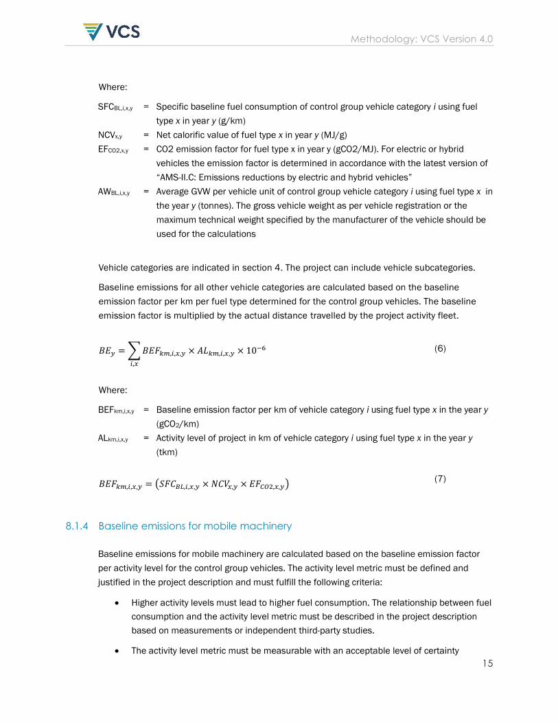
Where:
SFCBL,i,x,y = Specific baseline fuel consumption of control group vehicle category i using fuel
type x in year y (g/km)
NCVx,y = Net calorific value of fuel type x in year y (MJ/g)
EFCO2,x,y = CO2 emission factor for fuel type x in year y (gCO2/MJ). For electric or hybrid
vehicles the emission factor is determined in accordance with the latest version of
“AMS-II.C: Emissions reductions by electric and hybrid vehicles”
AWBL,i,x,y = Average GVW per vehicle unit of control group vehicle category i using fuel type x in
the year y (tonnes). The gross vehicle weight as per vehicle registration or the
maximum technical weight specified by the manufacturer of the vehicle should be
used for the calculations
Vehicle categories are indicated in section 4. The project can include vehicle subcategories.
Baseline emissions for all other vehicle categories are calculated based on the baseline
emission factor per km per fuel type determined for the control group vehicles. The baseline
emission factor is multiplied by the actual distance travelled by the project activity fleet.
𝐵𝐸𝑦 = ∑ 𝐵𝐸𝐹𝑘𝑚,𝑖,𝑥,𝑦 × 𝐴𝐿𝑘𝑚,𝑖,𝑥,𝑦 × 10−6
𝑖,𝑥
(6)
Where:
BEFkm,i,x,y = Baseline emission factor per km of vehicle category i using fuel type x in the year y
(gCO2/km)
ALkm,i,x,y = Activity level of project in km of vehicle category i using fuel type x in the year y
(tkm)
𝐵𝐸𝐹𝑘𝑚,𝑖,𝑥,𝑦 = (𝑆𝐹𝐶𝐵𝐿,𝑖,𝑥,𝑦 × 𝑁𝐶𝑉𝑥,𝑦 × 𝐸𝐹𝐶𝑂2,𝑥,𝑦) (7)
8.1.4 Baseline emissions for mobile machinery
Baseline emissions for mobile machinery are calculated based on the baseline emission factor
per activity level for the control group vehicles. The activity level metric must be defined and
justified in the project description and must fulfill the following criteria:
• Higher activity levels must lead to higher fuel consumption. The relationship between fuel
consumption and the activity level metric must be described in the project description
based on measurements or independent third-party studies.
• The activity level metric must be measurable with an acceptable level of certainty
Methodology: VCS Version 4.0
16
(acceptable data accuracy is ±10%).
• Changes in the relationship between fuel usage and activity level must be related to
efficiency or changes of fuel type used. In other words, such changes must not be
random or due to external factors not under the influence of the project. To demonstrate
this relationship, data from the sample to determine the baseline emission factor at the
lower boundary of the 90% confidence interval must have a deviation of less than 20%
from the average value. If this is not achieved, then more homogenous subgroups of
mobile machinery must be made. At validation, the demonstration that changes in fuel
consumption is directly related to efficiency or changes in fuel type are based on
qualitative arguments or ex-ante data. At verification, this demonstration is based on the
20% deviation check of the 90% confidence interval described above.
Activity level metrics may be related to the mobile machinery itself, or to the production output
(eg, amount of processed material). This is not a requirement, but rather an indication of how
activity level metrics may be defined. The project proponent must demonstrate at validation that
the activity level metric is appropriate to the project.
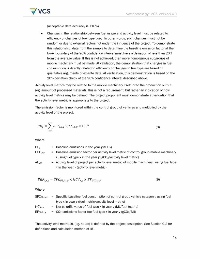
The emission factor is monitored within the control group of vehicles and multiplied by the
activity level of the project.
𝐵𝐸𝑦 = ∑ 𝐵𝐸𝐹𝑖,𝑥,𝑦 × 𝐴𝐿𝑖,𝑥,𝑦 × 10−6
𝑖,𝑥
(8)
Where:
BEy = Baseline emissions in the year y (tCO2)
BEFi,x,y = Baseline emission factor per activity level metric of control group mobile machinery
i using fuel type x in the year y (gCO2/activity level metric)
ALi,x,y = Activity level of project per activity level metric of mobile machinery i using fuel type
x in the year y (activity level metric)
𝐵𝐸𝐹𝑖,𝑥,𝑦 = 𝑆𝐹𝐶𝐵𝐿,𝑖,𝑥,𝑦 × 𝑁𝐶𝑉𝑥,𝑦 × 𝐸𝐹𝐶𝑂2,𝑥,𝑦 (9)
Where:
SFCBL,i,x,y = Specific baseline fuel consumption of control group vehicle category i using fuel
type x in year y (fuel metric/activity level metric)
NCVx,y = Net calorific value of fuel type x in year y (MJ/fuel metric)
EFCO2,x,y = CO2 emissions factor foe fuel type x in year y (gCO2/MJ)
The activity level metric AL (eg, hours) is defined by the project description. See Section 9.2 for
definitions and calculation method of AL.
Methodology: VCS Version 4.0
17
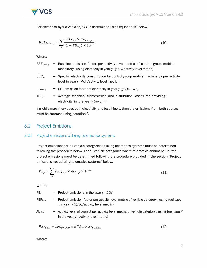
For electric or hybrid vehicles, BEF is determined using equation 10 below.
𝐵𝐸𝐹𝑖,𝑒𝑙𝑒𝑐,𝑦 = ∑𝑆𝐸𝐶𝑖,𝑦 × 𝐸𝐹𝑒𝑙𝑒𝑐,𝑦
(1 − 𝑇𝐷𝐿𝑦) × 10−3𝑖
(10)
Where:
BEFi,elec,y = Baseline emission factor per activity level metric of control group mobile
machinery i using electricity in year y (gCO2/activity level metric)
SECi,y = Specific electricity consumption by control group mobile machinery i per activity
level in year y (kWh/activity level metric)
EFelec,y = CO2 emission factor of electricity in year y (gCO2/kWh)
TDLy = Average technical transmission and distribution losses for providing
electricity in the year y (no unit)
If mobile machinery uses both electricity and fossil fuels, then the emissions from both sources
must be summed using equation 8.
8.2 Project Emissions
8.2.1 Project emissions utilizing telematics systems
Project emissions for all vehicle categories utilizing telematics systems must be determined
following the procedure below. For all vehicle categories where telematics cannot be utilized,
project emissions must be determined following the procedure provided in the section “Project
emissions not utilizing telematics systems” below.
𝑃𝐸𝑦 = ∑ 𝑃𝐸𝐹𝑖,𝑥,𝑦 × 𝐴𝐿𝑖,𝑥,𝑦 × 10−6
𝑖,𝑥
(11)
Where:
PEy = Project emissions in the year y (tCO2)
PEFi,x,y = Project emission factor per activity level metric of vehicle category i using fuel type
x in year y (gCO2/activity level metric)
ALi,x,y = Activity level of project per activity level metric of vehicle category i using fuel type x
in the year y (activity level metric)
𝑃𝐸𝐹𝑖,𝑥,𝑦 = 𝑆𝐹𝐶𝑃𝐽,𝑖,𝑥,𝑦 × 𝑁𝐶𝑉𝑥,𝑦 × 𝐸𝐹𝐶𝑂2,𝑥,𝑦 (12)
Where:
Methodology: VCS Version 4.0
18
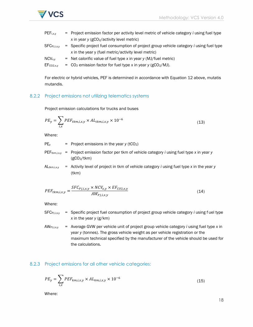
PEFi,x,y = Project emission factor per activity level metric of vehicle category i using fuel type
x in year y (gCO2/activity level metric)
SFCPJ,i,x,y = Specific project fuel consumption of project group vehicle category i using fuel type
x in the year y (fuel metric/activity level metric)
NCVx,y = Net calorific value of fuel type x in year y (MJ/fuel metric)
EFCO2,x,y = CO2 emission factor for fuel type x in year y (gCO2/MJ).
For electric or hybrid vehicles, PEF is determined in accordance with Equation 12 above, mutatis
mutandis.
8.2.2 Project emissions not utilizing telematics systems
Project emission calculations for trucks and buses
𝑃𝐸𝑦 = ∑ 𝑃𝐸𝐹𝑡𝑘𝑚,𝑖,𝑥,𝑦 × 𝐴𝐿𝑡𝑘𝑚,𝑖,𝑥,𝑦 × 10−6
𝑖,𝑥
(13)
Where:
PEy = Project emissions in the year y (tCO2)
PEFtkm,i,x,y = Project emission factor per tkm of vehicle category i using fuel type x in year y
(gCO2/tkm)
ALtkm,i,x,y = Activity level of project in tkm of vehicle category i using fuel type x in the year y
(tkm)
𝑃𝐸𝐹𝑡𝑘𝑚,𝑖,𝑥,𝑦 =𝑆𝐹𝐶𝑃𝐽,𝑖,𝑥,𝑦 × 𝑁𝐶𝑉𝑥,𝑦 × 𝐸𝐹𝐶𝑂2,𝑥,𝑦
𝐴𝑊𝑃𝐽,𝑖,𝑥,𝑦 (14)
Where:
SFCPJ,i,x,y = Specific project fuel consumption of project group vehicle category i using f uel type
x in the year y (g/km)
AWPJ,i,x,y = Average GVW per vehicle unit of project group vehicle category i using fuel type x in
year y (tonnes). The gross vehicle weight as per vehicle registration or the
maximum technical specified by the manufacturer of the vehicle should be used for
the calculations.
8.2.3 Project emissions for all other vehicle categories:
𝑃𝐸𝑦 = ∑ 𝑃𝐸𝐹𝑘𝑚,𝑖,𝑥,𝑦 × 𝐴𝐿𝑘𝑚,𝑖,𝑥,𝑦 × 10−6
𝑖,𝑥
(15)
Where:
Methodology: VCS Version 4.0
19
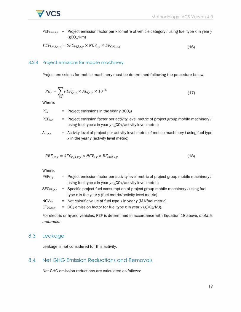
PEFkm,i,x,y = Project emission factor per kilometre of vehicle category i using fuel type x in year y
(gCO2/km)
𝑃𝐸𝐹𝑘𝑚,𝑖,𝑥,𝑦 = 𝑆𝐹𝐶𝑃𝐽,𝑖,𝑥,𝑦 × 𝑁𝐶𝑉𝑥,𝑦 × 𝐸𝐹𝐶𝑂2,𝑥,𝑦 (16)
8.2.4 Project emissions for mobile machinery
Project emissions for mobile machinery must be determined following the procedure below.
𝑃𝐸𝑦 = ∑ 𝑃𝐸𝐹𝑖,𝑥,𝑦 × 𝐴𝐿𝑖,𝑥,𝑦 × 10−6
𝑖,𝑥
(17)
Where:
PEy = Project emissions in the year y (tCO2)
PEFi,x,y = Project emission factor per activity level metric of project group mobile machinery i
using fuel type x in year y (gCO2/activity level metric)
ALi,x,y = Activity level of project per activity level metric of mobile machinery i using fuel type
x in the year y (activity level metric)
𝑃𝐸𝐹𝑖,𝑥,𝑦 = 𝑆𝐹𝐶𝑃𝐽,𝑖,𝑥,𝑦 × 𝑁𝐶𝑉𝑥,𝑦 × 𝐸𝐹𝐶𝑂2,𝑥,𝑦 (18)
Where:
PEFi,x,y = Project emission factor per activity level metric of project group mobile machinery i
using fuel type x in year y (gCO2/activity level metric)
SFCPJ,i,x,y = Specific project fuel consumption of project group mobile machinery i using fuel
type x in the year y (fuel metric/activity level metric)
NCVx,y = Net calorific value of fuel type x in year y (MJ/fuel metric)
EFCO2,x,y = CO2 emission factor for fuel type x in year y (gCO2/MJ).
For electric or hybrid vehicles, PEF is determined in accordance with Equation 18 above, mutatis
mutandis.
8.3 Leakage
Leakage is not considered for this activity.
8.4 Net GHG Emission Reductions and Removals
Net GHG emission reductions are calculated as follows:
Methodology: VCS Version 4.0
20
𝐸𝑅𝑦 = 𝐵𝐸𝑦 − 𝑃𝐸𝑦 − 𝐿𝐸𝑦 (19)
Where:
ERY = Net GHG emissions reductions and removals in year y (tCO2e)
BEY = Baseline emissions in year y (tCO2e)
PEy = Project emissions in year y (tCO2e)
LEy = Leakage in year y (tCO2e)
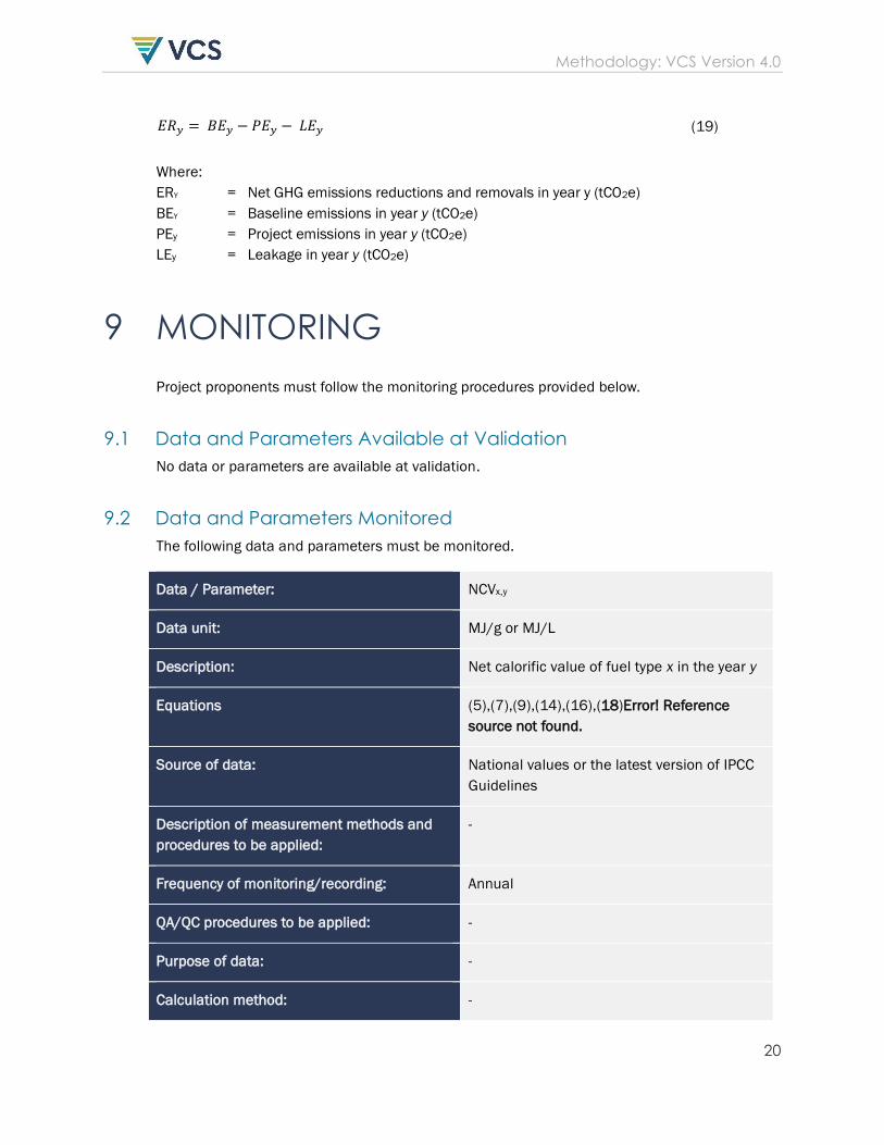
9 MONITORING
Project proponents must follow the monitoring procedures provided below.
9.1 Data and Parameters Available at Validation
No data or parameters are available at validation.
9.2 Data and Parameters Monitored
The following data and parameters must be monitored.
Data / Parameter: NCVx,y
Data unit: MJ/g or MJ/L
Description: Net calorific value of fuel type x in the year y
Equations (5),(7),(9),(14),(16),(18)Error! Reference
source not found.
Source of data: National values or the latest version of IPCC
Guidelines
Description of measurement methods and
procedures to be applied:
-
Frequency of monitoring/recording: Annual
QA/QC procedures to be applied: -
Purpose of data: -
Calculation method: -
Methodology: VCS Version 4.0
21
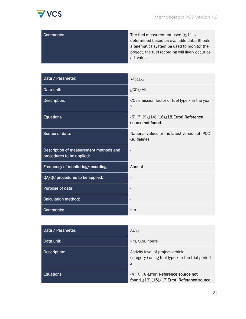
Comments: The fuel measurement used (g, L) is
determined based on available data. Should
a telematics system be used to monitor the
project, the fuel recording will likely occur as
a L value.
Data / Parameter: EFCO2,x,y
Data unit: gCO2/MJ
Description: CO2 emission factor of fuel type x in the year
y
Equations (5),(7),(9),(14),(16),(18)Error! Reference
source not found.
Source of data: National values or the latest version of IPCC
Guidelines
Description of measurement methods and
procedures to be applied:
-
Frequency of monitoring/recording: Annual
QA/QC procedures to be applied: -
Purpose of data: -
Calculation method: -
Comments: km
Data / Parameter: ALi,x,y
Data unit: km, tkm, hours
Description: Activity level of project vehicle
category i using fuel type x in the trial period
z
Equations (4),(6),(8)Error! Reference source not
found.,(13),(15),(17)Error! Reference source
Methodology: VCS Version 4.0
22
not found.
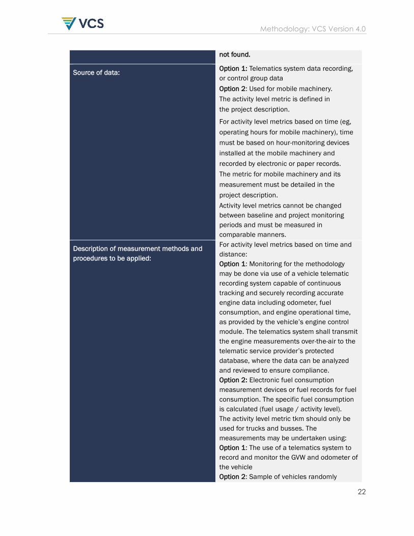
Source of data: Option 1: Telematics system data recording,
or control group data
Option 2: Used for mobile machinery.
The activity level metric is defined in
the project description.
For activity level metrics based on time (eg,
operating hours for mobile machinery), time
must be based on hour-monitoring devices
installed at the mobile machinery and
recorded by electronic or paper records.
The metric for mobile machinery and its
measurement must be detailed in the
project description.
Activity level metrics cannot be changed
between baseline and project monitoring
periods and must be measured in
comparable manners.
Description of measurement methods and
procedures to be applied:
For activity level metrics based on time and
distance:
Option 1: Monitoring for the methodology
may be done via use of a vehicle telematic
recording system capable of continuous
tracking and securely recording accurate
engine data including odometer, fuel
consumption, and engine operational time,
as provided by the vehicle’s engine control
module. The telematics system shall transmit
the engine measurements over-the-air to the
telematic service provider’s protected
database, where the data can be analyzed
and reviewed to ensure compliance.
Option 2: Electronic fuel consumption
measurement devices or fuel records for fuel
consumption. The specific fuel consumption
is calculated (fuel usage / activity level).
The activity level metric tkm should only be
used for trucks and busses. The
measurements may be undertaken using:
Option 1: The use of a telematics system to
record and monitor the GVW and odometer of
the vehicle
Option 2: Sample of vehicles randomly
Methodology: VCS Version 4.0
23
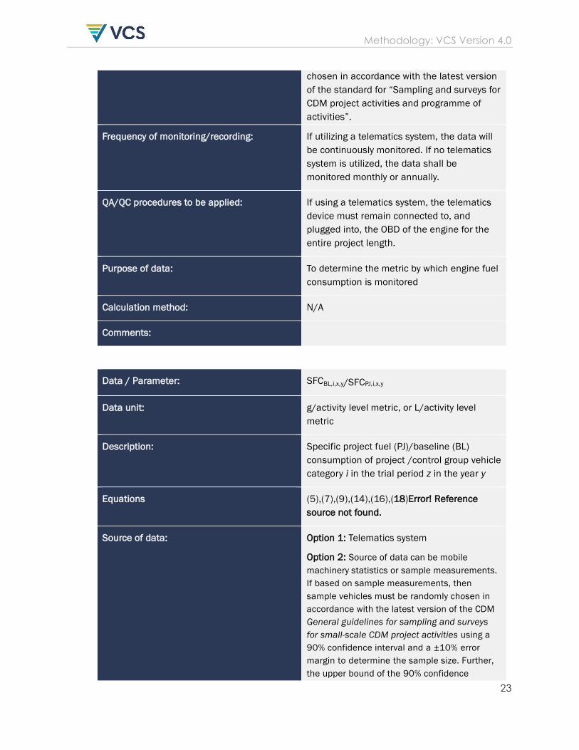
chosen in accordance with the latest version
of the standard for “Sampling and surveys for
CDM project activities and programme of
activities”.
Frequency of monitoring/recording: If utilizing a telematics system, the data will
be continuously monitored. If no telematics
system is utilized, the data shall be
monitored monthly or annually.
QA/QC procedures to be applied: If using a telematics system, the telematics
device must remain connected to, and
plugged into, the OBD of the engine for the
entire project length.
Purpose of data: To determine the metric by which engine fuel
consumption is monitored
Calculation method: N/A
Comments:
Data / Parameter: SFCBL,i,x,y/SFCPJ,i,x,y
Data unit: g/activity level metric, or L/activity level
metric
Description: Specific project fuel (PJ)/baseline (BL)
consumption of project /control group vehicle
category i in the trial period z in the year y
Equations (5),(7),(9),(14),(16),(18)Error! Reference
source not found.
Source of data: Option 1: Telematics system
Option 2: Source of data can be mobile
machinery statistics or sample measurements.
If based on sample measurements, then
sample vehicles must be randomly chosen in
accordance with the latest version of the CDM
General guidelines for sampling and surveys
for small-scale CDM project activities using a
90% confidence interval and a ±10% error
margin to determine the sample size. Further,
the upper bound of the 90% confidence
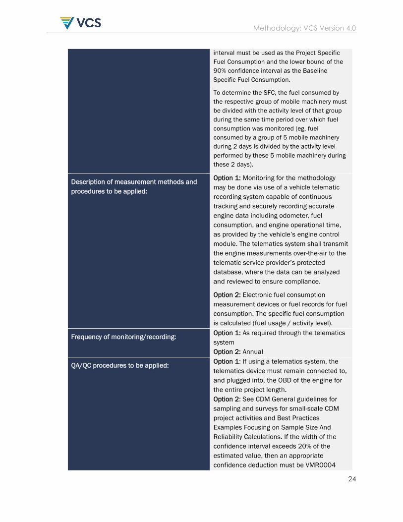
Methodology: VCS Version 4.0
24
interval must be used as the Project Specific
Fuel Consumption and the lower bound of the
90% confidence interval as the Baseline
Specific Fuel Consumption.
To determine the SFC, the fuel consumed by
the respective group of mobile machinery must
be divided with the activity level of that group
during the same time period over which fuel
consumption was monitored (eg, fuel
consumed by a group of 5 mobile machinery
during 2 days is divided by the activity level
performed by these 5 mobile machinery during
these 2 days).
Description of measurement methods and
procedures to be applied:
Option 1: Monitoring for the methodology
may be done via use of a vehicle telematic
recording system capable of continuous
tracking and securely recording accurate
engine data including odometer, fuel
consumption, and engine operational time,
as provided by the vehicle’s engine control
module. The telematics system shall transmit
the engine measurements over-the-air to the
telematic service provider’s protected
database, where the data can be analyzed
and reviewed to ensure compliance.
Option 2: Electronic fuel consumption
measurement devices or fuel records for fuel
consumption. The specific fuel consumption
is calculated (fuel usage / activity level).
Frequency of monitoring/recording: Option 1: As required through the telematics
system
Option 2: Annual
QA/QC procedures to be applied: Option 1: If using a telematics system, the
telematics device must remain connected to,
and plugged into, the OBD of the engine for
the entire project length.
Option 2: See CDM General guidelines for
sampling and surveys for small-scale CDM
project activities and Best Practices
Examples Focusing on Sample Size And
Reliability Calculations. If the width of the
confidence interval exceeds 20% of the
estimated value, then an appropriate
confidence deduction must be VMR0004
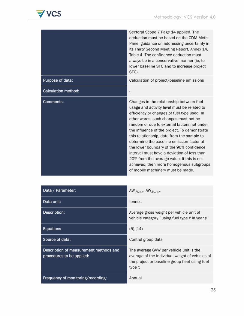
Methodology: VCS Version 4.0
25
Sectoral Scope 7 Page 14 applied. The
deduction must be based on the CDM Meth
Panel guidance on addressing uncertainty in
its Thirty Second Meeting Report, Annex 14,
Table 4. The confidence deduction must
always be in a conservative manner (ie, to
lower baseline SFC and to increase project
SFC).
Purpose of data: Calculation of project/baseline emissions
Calculation method: -
Comments: Changes in the relationship between fuel
usage and activity level must be related to
efficiency or changes of fuel type used. In
other words, such changes must not be
random or due to external factors not under
the influence of the project. To demonstrate
this relationship, data from the sample to
determine the baseline emission factor at
the lower boundary of the 90% confidence
interval must have a deviation of less than
20% from the average value. If this is not
achieved, then more homogenous subgroups
of mobile machinery must be made.
Data / Parameter: AW,PJ,I,x,y, AW,BL,I,x,y
Data unit: tonnes
Description: Average gross weight per vehicle unit of
vehicle category i using fuel type x in year y
Equations (5),(14)
Source of data: Control group data
Description of measurement methods and
procedures to be applied:
The average GVW per vehicle unit is the
average of the individual weight of vehicles of
the project or baseline group fleet using fuel
type x
Frequency of monitoring/recording: Annual
Methodology: VCS Version 4.0
26
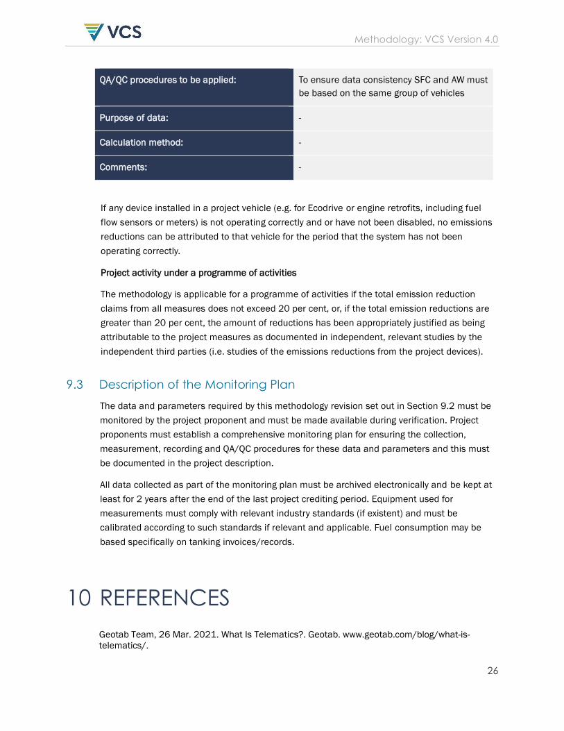
QA/QC procedures to be applied: To ensure data consistency SFC and AW must
be based on the same group of vehicles
Purpose of data: -
Calculation method: -
Comments: -
If any device installed in a project vehicle (e.g. for Ecodrive or engine retrofits, including fuel
flow sensors or meters) is not operating correctly and or have not been disabled, no emissions
reductions can be attributed to that vehicle for the period that the system has not been
operating correctly.
Project activity under a programme of activities
The methodology is applicable for a programme of activities if the total emission reduction
claims from all measures does not exceed 20 per cent, or, if the total emission reductions are
greater than 20 per cent, the amount of reductions has been appropriately justified as being
attributable to the project measures as documented in independent, relevant studies by the
independent third parties (i.e. studies of the emissions reductions from the project devices).
9.3 Description of the Monitoring Plan
The data and parameters required by this methodology revision set out in Section 9.2 must be
monitored by the project proponent and must be made available during verification. Project
proponents must establish a comprehensive monitoring plan for ensuring the collection,
measurement, recording and QA/QC procedures for these data and parameters and this must
be documented in the project description.
All data collected as part of the monitoring plan must be archived electronically and be kept at
least for 2 years after the end of the last project crediting period. Equipment used for
measurements must comply with relevant industry standards (if existent) and must be
calibrated according to such standards if relevant and applicable. Fuel consumption may be
based specifically on tanking invoices/records.
10 REFERENCES
Geotab Team, 26 Mar. 2021. What Is Telematics?. Geotab. www.geotab.com/blog/what-is-
telematics/.

Methodology: VCS Version 4.0
27
Davies, T., 2003. Calculation of CO2 Emissions from Fuels, Exeter.
people.exeter.ac.uk/TWDavies/energy_conversion/Calculation%20of%20CO2%20emissions%20f
rom%20fuels.htm.
Grutter, J. et al., 2013. Approved VCS Methodology Revision VMR0004. verra.org/wp-
content/uploads/2018/03/VMR0004-Revisions-to-AMS-III.BC-to-Include-Mobile-Machinery-
v1.0.pdf.