Embed Size (px)
Citation preview
Methods of AnalysisMethods of Analysis PSUTPSUT 11
Basic Nodal and Mesh Analysis
Al-Qaralleh
Methods of AnalysisMethods of Analysis
PSUTPSUTMethods of AnalysisMethods of Analysis 22
• Introduction
• Nodal analysis
• Nodal analysis with voltage source
• Mesh analysis
• Mesh analysis with current source
• Nodal and mesh analyses by inspection
• Nodal versus mesh analysis
Lect4Lect4EEE 202EEE 202 33
Steps of Nodal AnalysisSteps of Nodal Analysis
1. Choose a reference (ground) node.
2. Assign node voltages to the other nodes.
3. Apply KCL to each node other than the reference node; express currents in terms of node voltages.
4. Solve the resulting system of linear equations for the nodal voltages.
PSUTPSUTMethods of AnalysisMethods of Analysis 44
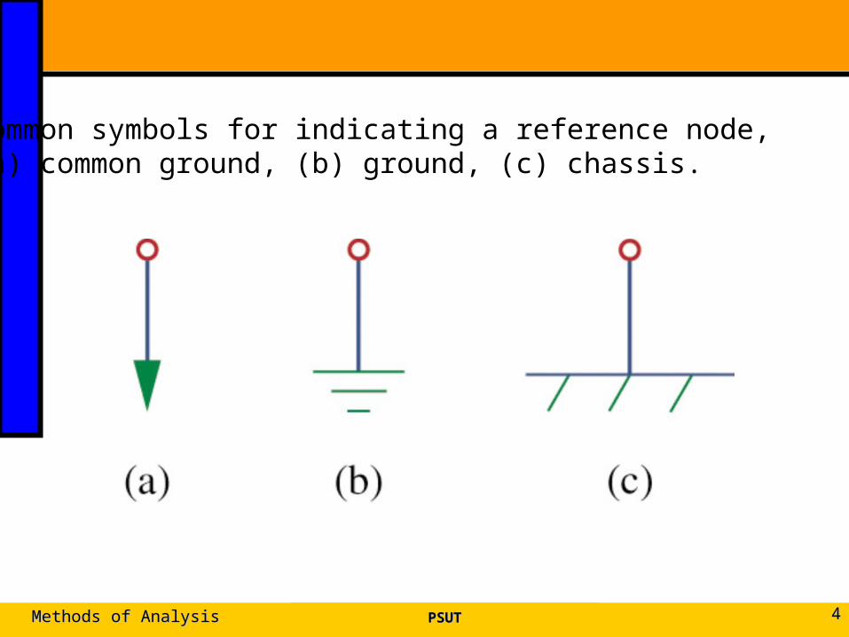
Common symbols for indicating a reference node, (a) common ground, (b) ground, (c) chassis.
Lect4Lect4EEE 202EEE 202 55
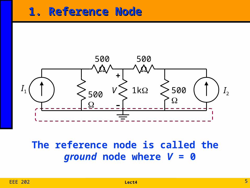
1. Reference Node1. Reference Node
The reference node is called the ground node where V = 0
+
–
V 500
500
1k
500
500I1 I2
Lect4Lect4EEE 202EEE 202 66
Steps of Nodal AnalysisSteps of Nodal Analysis
1. Choose a reference (ground) node.
2. Assign node voltages to the other nodes.
3. Apply KCL to each node other than the reference node; express currents in terms of node voltages.
4. Solve the resulting system of linear equations for the nodal voltages.
Lect4Lect4EEE 202EEE 202 77
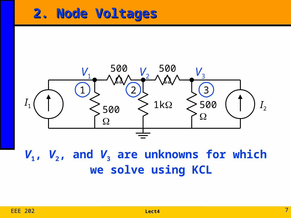
2. Node Voltages2. Node Voltages
V1, V2, and V3 are unknowns for which we solve using KCL
500
500
1k
500
500I1 I2
1 2 3
V1 V2 V3
Lect4Lect4EEE 202EEE 202 88
Steps of Nodal AnalysisSteps of Nodal Analysis
1. Choose a reference (ground) node.
2. Assign node voltages to the other nodes.
3. Apply KCL to each node other than the reference node; express currents in terms of node voltages.
4. Solve the resulting system of linear equations for the nodal voltages.
Lect4Lect4EEE 202EEE 202 99
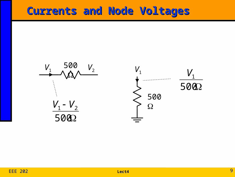
Currents and Node VoltagesCurrents and Node Voltages
500
V1500V1 V2
50021 VV
5001V

Lect4Lect4EEE 202EEE 202 1010
3. KCL at Node 13. KCL at Node 1
500
500I1
V1 V2
500500
1211
VVVI
Lect4Lect4EEE 202EEE 202 1111
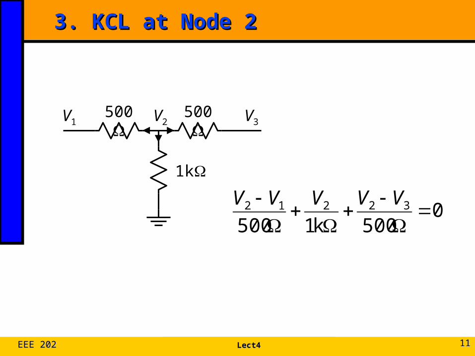
3. KCL at Node 23. KCL at Node 2
500
1k
500 V2 V3V1
0500k1500
32212
VVVVV
Lect4Lect4EEE 202EEE 202 1212
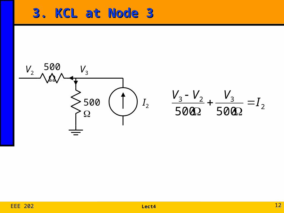
3. KCL at Node 33. KCL at Node 3
2323
500500I
VVV
500
500
I2
V2 V3
Lect4Lect4EEE 202EEE 202 1313
Steps of Nodal AnalysisSteps of Nodal Analysis
1. Choose a reference (ground) node.
2. Assign node voltages to the other nodes.
3. Apply KCL to each node other than the reference node; express currents in terms of node voltages.
4. Solve the resulting system of linear equations for the nodal voltages.
Lect4Lect4EEE 202EEE 202 1414
+
–
V 500
500
1k
500
500I1 I2
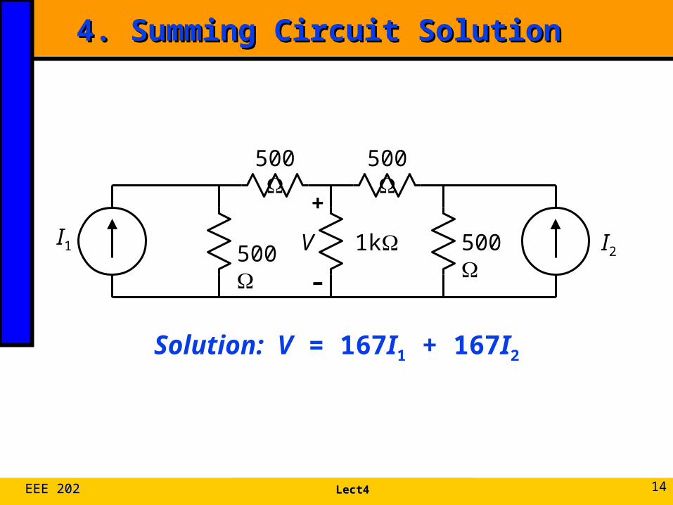
4. Summing Circuit Solution4. Summing Circuit Solution
Solution: V = 167I1 + 167I2
PSUTPSUTMethods of AnalysisMethods of Analysis 1515
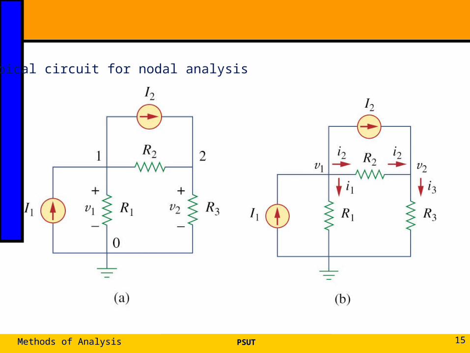
Typical circuit for nodal analysis
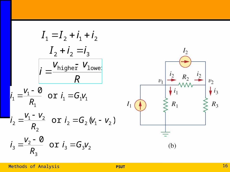
PSUTPSUTMethods of AnalysisMethods of Analysis 1616
322
2121
iiI
iiII
R
vvi lowerhigher
2333
23
21222
212
1111
11
or 0
)(or
or 0
vGiRv
i
vvGiRvv
i
vGiRv
i
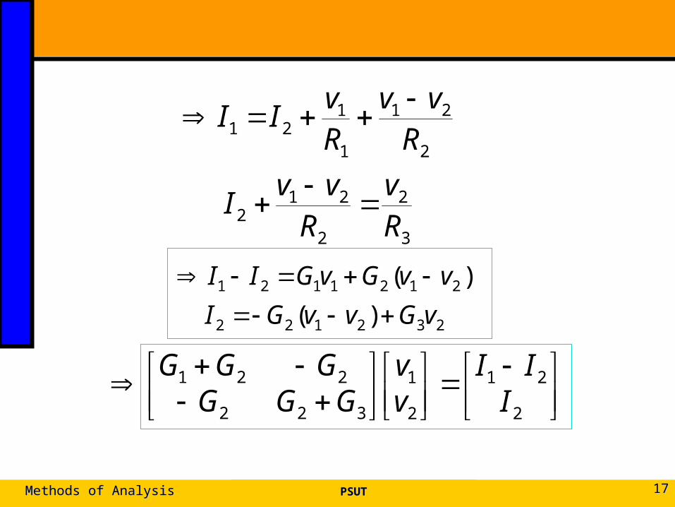
PSUTPSUTMethods of AnalysisMethods of Analysis 1717
3
2
2
212
2
21
1
121
Rv
Rvv
I
Rvv
Rv
II
232122
2121121
)(
)(
vGvvGI
vvGvGII
2
21
2
1
322
221
III
vv
GGGGGG
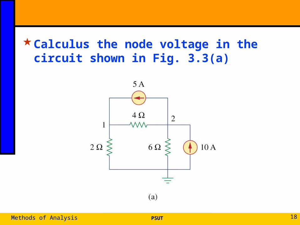
Calculus the node voltage in the circuit shown in Fig. 3.3(a)
PSUTPSUTMethods of AnalysisMethods of Analysis 1818
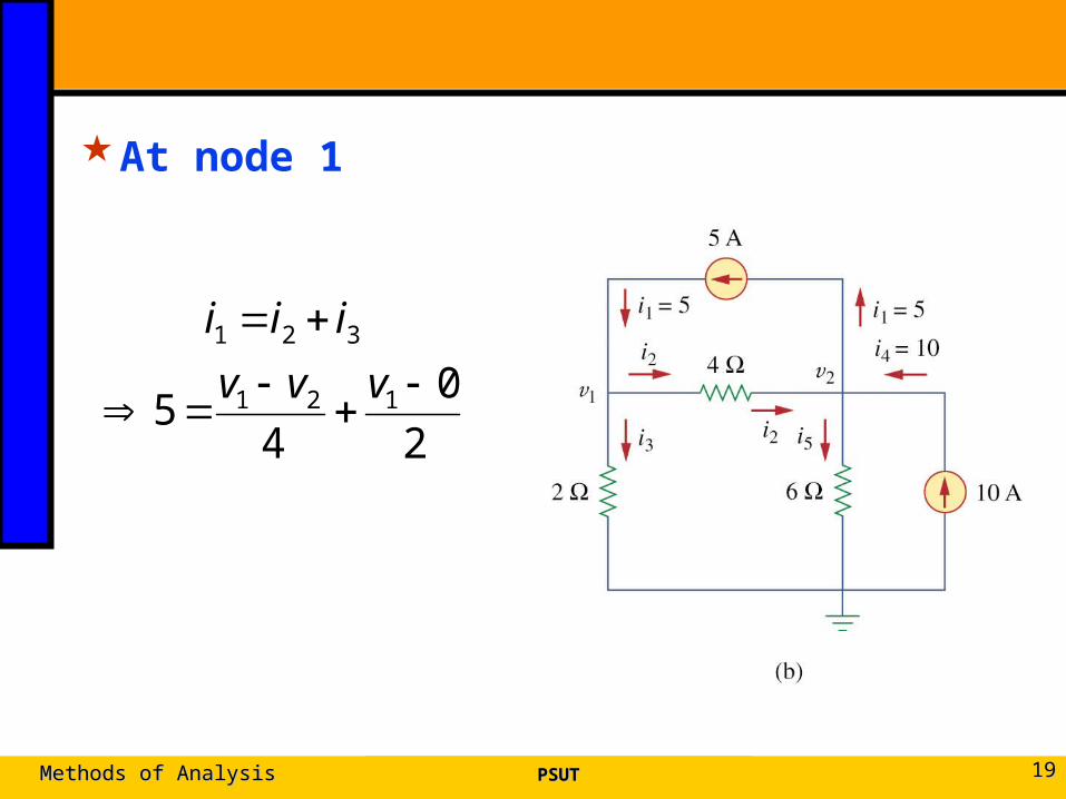
At node 1
PSUTPSUTMethods of AnalysisMethods of Analysis 1919
2
0
45 121
321
vvv
iii
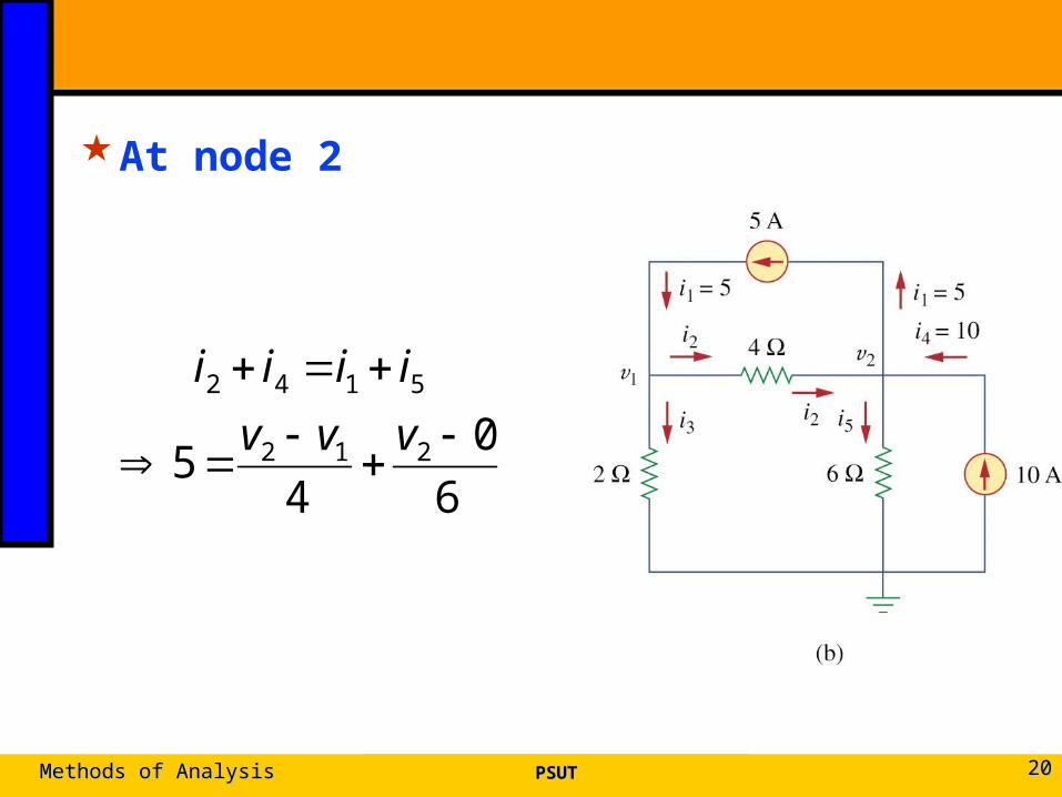
At node 2
PSUTPSUTMethods of AnalysisMethods of Analysis 2020
6
0
45 212
5142
vvv
iiii
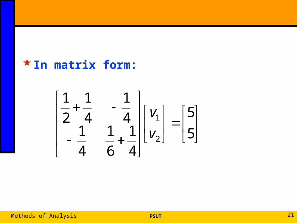
In matrix form:
PSUTPSUTMethods of AnalysisMethods of Analysis 2121
5
5
4
1
6
1
4
14
1
4
1
2
1
2
1
v
v
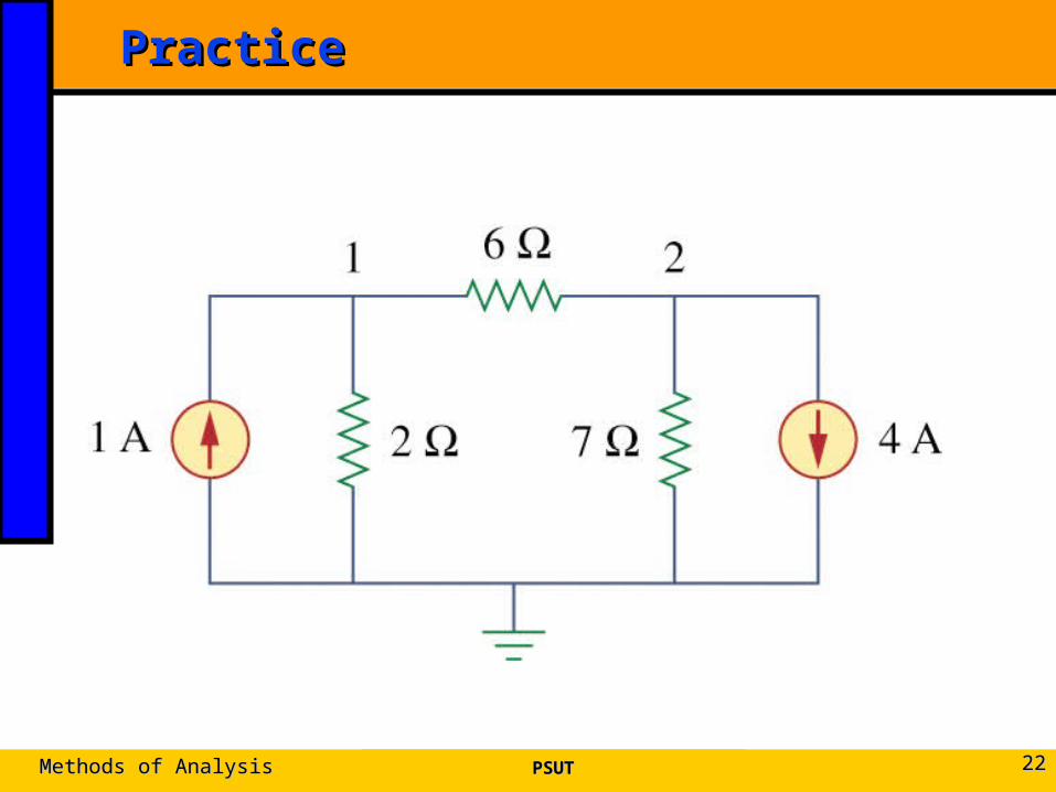
PracticePractice
PSUTPSUTMethods of AnalysisMethods of Analysis 2222
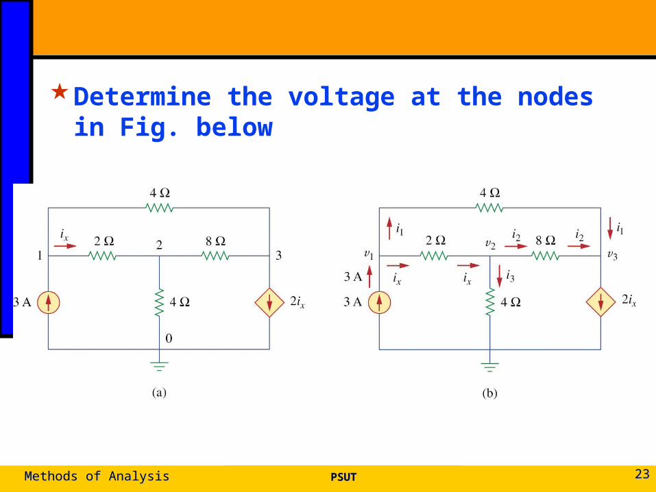
Determine the voltage at the nodes in Fig. below
PSUTPSUTMethods of AnalysisMethods of Analysis 2323
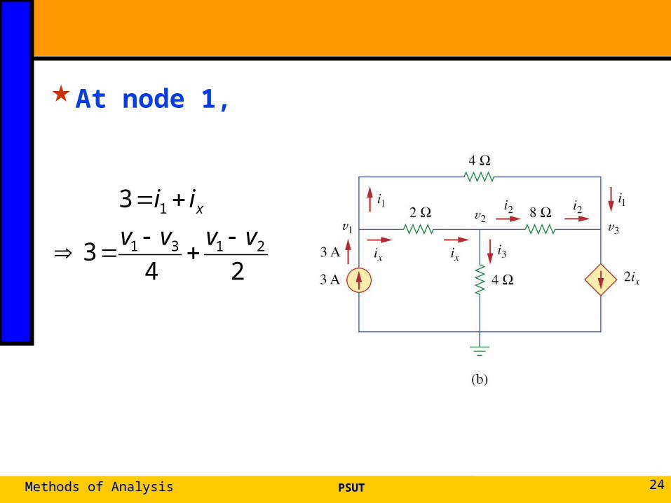
At node 1,
PSUTPSUTMethods of AnalysisMethods of Analysis 2424
243
3
2131
1
vvvv
ii x
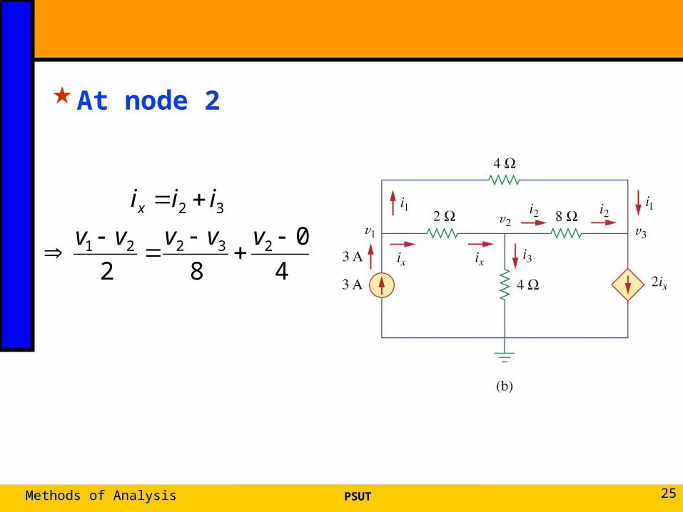
At node 2
PSUTPSUTMethods of AnalysisMethods of Analysis 2525
4
0
8223221
32
vvvvv
iiix
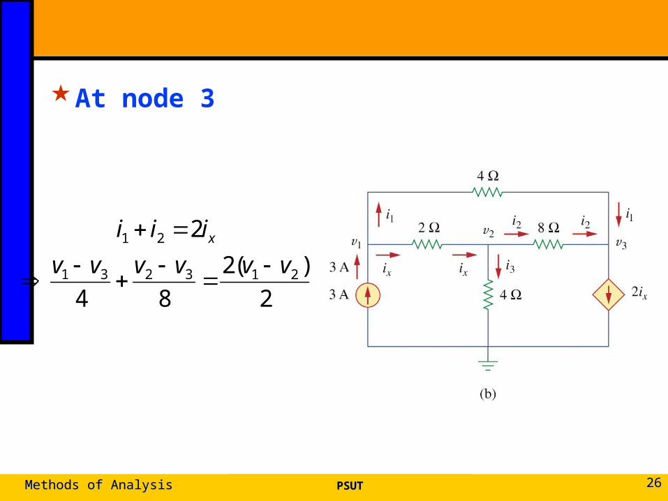
At node 3
PSUTPSUTMethods of AnalysisMethods of Analysis 2626
2
)(2
84
2
213231
21
vvvvvv
iii x
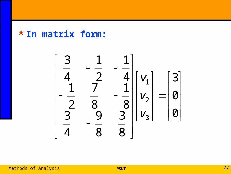
In matrix form:
PSUTPSUTMethods of AnalysisMethods of Analysis 2727
0
0
3
8
3
8
9
4
38
1
8
7
2
14
1
2
1
4
3
3
2
1
v
v
v
3.3 3.3 Nodal Analysis with Voltage SourcesNodal Analysis with Voltage Sources
Case 1: The voltage source is connected between a nonreference node and the reference node: The nonreference node voltage is equal to the magnitude of voltage source and the number of unknown nonreference nodes is reduced by one.
Case 2: The voltage source is connected between two nonreferenced nodes: a generalized node (supernode) is formed.
PSUTPSUTMethods of AnalysisMethods of Analysis 2828
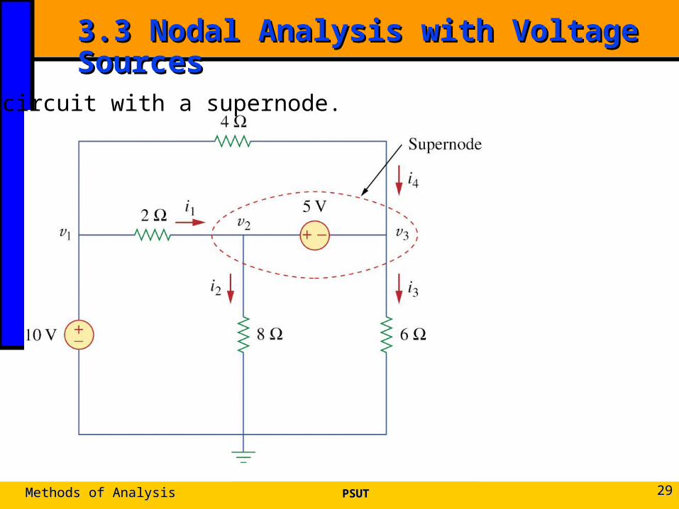
3.3 Nodal Analysis with Voltage Sources3.3 Nodal Analysis with Voltage Sources
56
0
8
0
42
32
323121
3241
vv
vvvvvv
iiii
PSUTPSUTMethods of AnalysisMethods of Analysis 2929
A circuit with a supernode.
A supernode is formed by enclosing a (dependent or independent) voltage source connected between two nonreference nodes and any elements connected in parallel with it.
The required two equations for regulating the two nonreference node voltages are obtained by the KCL of the supernode and the relationship of node voltages due to the voltage source.
PSUTPSUTMethods of AnalysisMethods of Analysis 3030
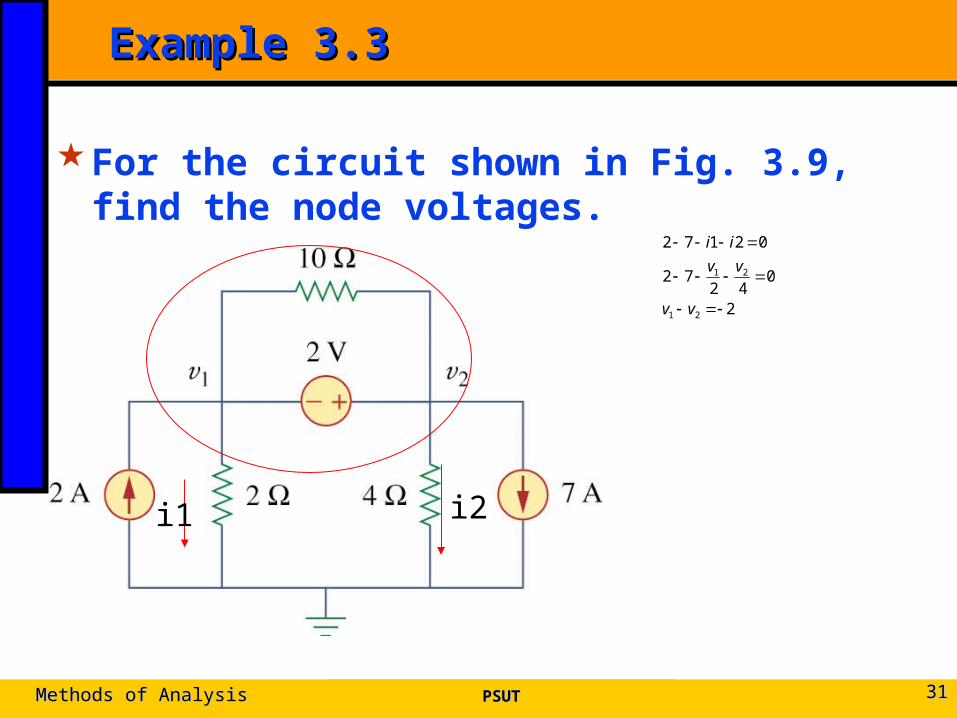
Example 3.3Example 3.3
For the circuit shown in Fig. 3.9, find the node voltages.
2
042
72
02172
21
21
vv
vv
ii
PSUTPSUTMethods of AnalysisMethods of Analysis 3131
i1 i2
PSUTPSUTMethods of AnalysisMethods of Analysis 3232
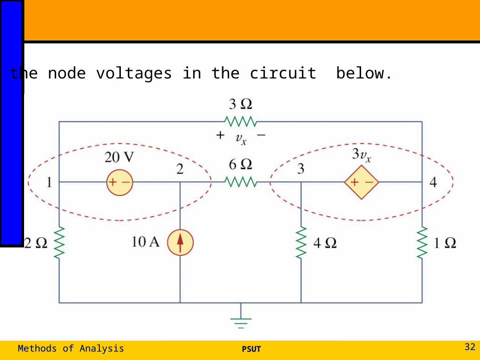
Find the node voltages in the circuit below.

At suopernode 1-2,
PSUTPSUTMethods of AnalysisMethods of Analysis 3333
2023
106
21
14123
vv
vvvvv
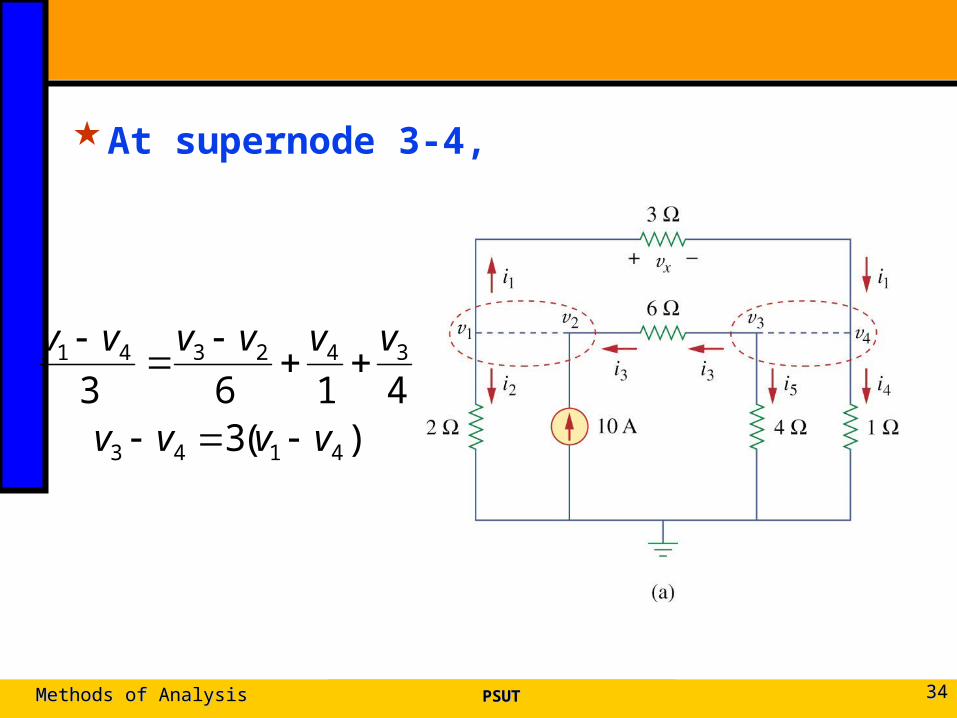
At supernode 3-4,
PSUTPSUTMethods of AnalysisMethods of Analysis 3434
)(34163
4143
342341
vvvv
vvvvvv
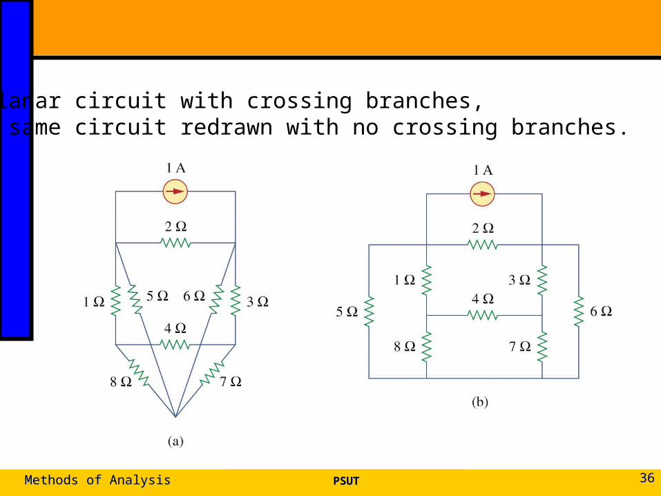
3.4 Mesh Analysis3.4 Mesh Analysis
Mesh analysis: another procedure for analyzing circuits, applicable to planar circuit.
A Mesh is a loop which does not contain any other loops within it
PSUTPSUTMethods of AnalysisMethods of Analysis 3535
PSUTPSUTMethods of AnalysisMethods of Analysis 3636
(a) A Planar circuit with crossing branches,(b) The same circuit redrawn with no crossing branches.
PSUTPSUTMethods of AnalysisMethods of Analysis 3737
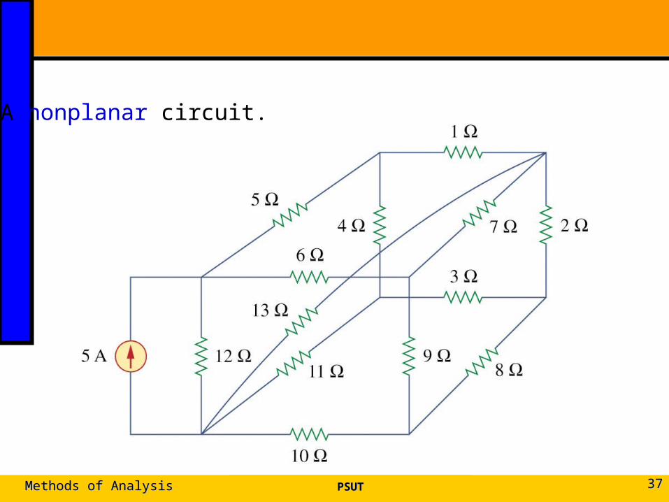
A nonplanar circuit.
Steps to Determine Mesh Currents:
1. Assign mesh currents i1, i2, .., in to the n meshes.
2. Apply KVL to each of the n meshes. Use Ohm’s law to express the voltages in terms of the mesh currents.
3. Solve the resulting n simultaneous equations to get the mesh currents.
PSUTPSUTMethods of AnalysisMethods of Analysis 3838
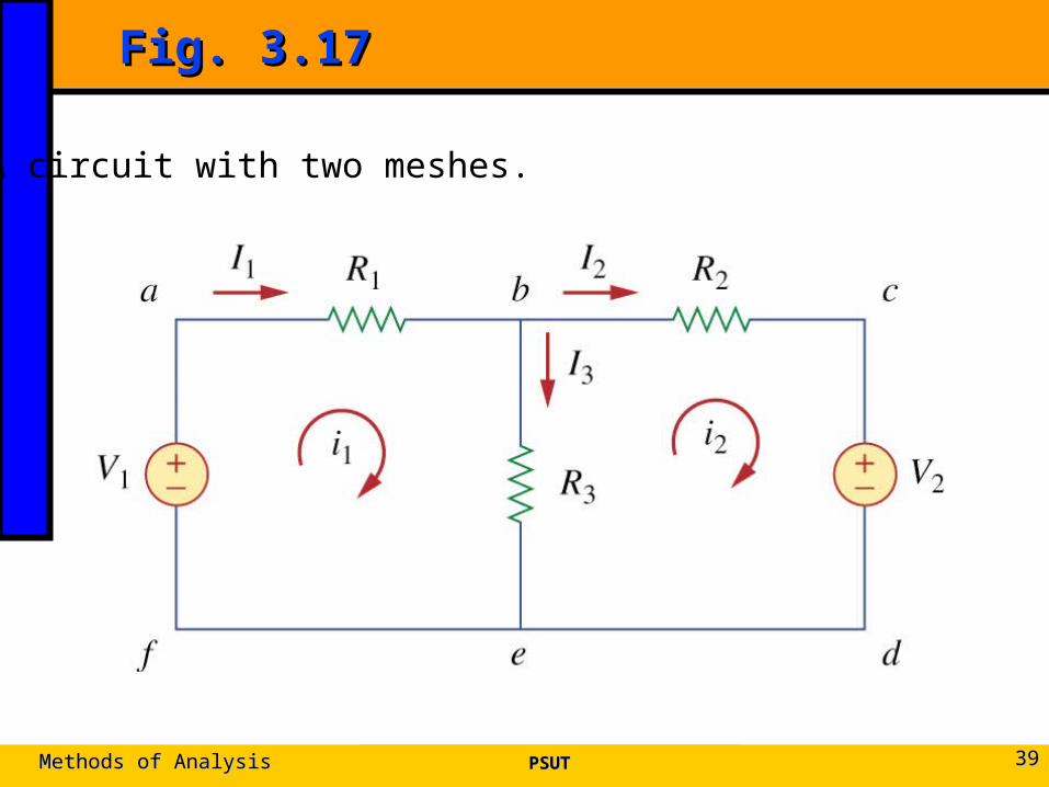
Fig. 3.17Fig. 3.17
PSUTPSUTMethods of AnalysisMethods of Analysis 3939
A circuit with two meshes.
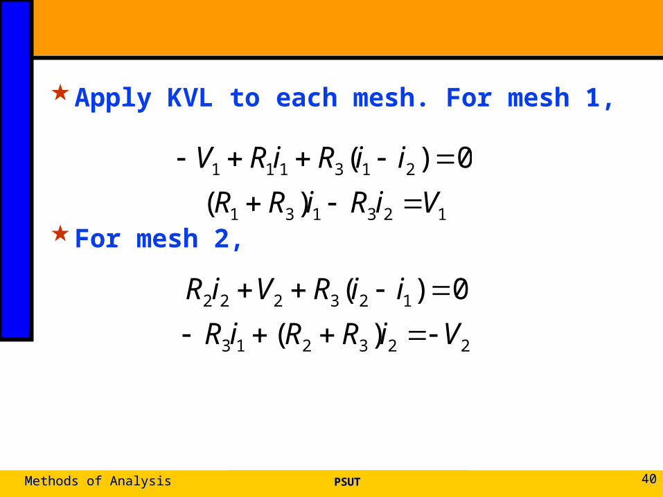
Apply KVL to each mesh. For mesh 1,
For mesh 2,
PSUTPSUTMethods of AnalysisMethods of Analysis 4040
123131
213111
)(
0)(
ViRiRR
iiRiRV
223213
123222
)(
0)(
ViRRiR
iiRViR
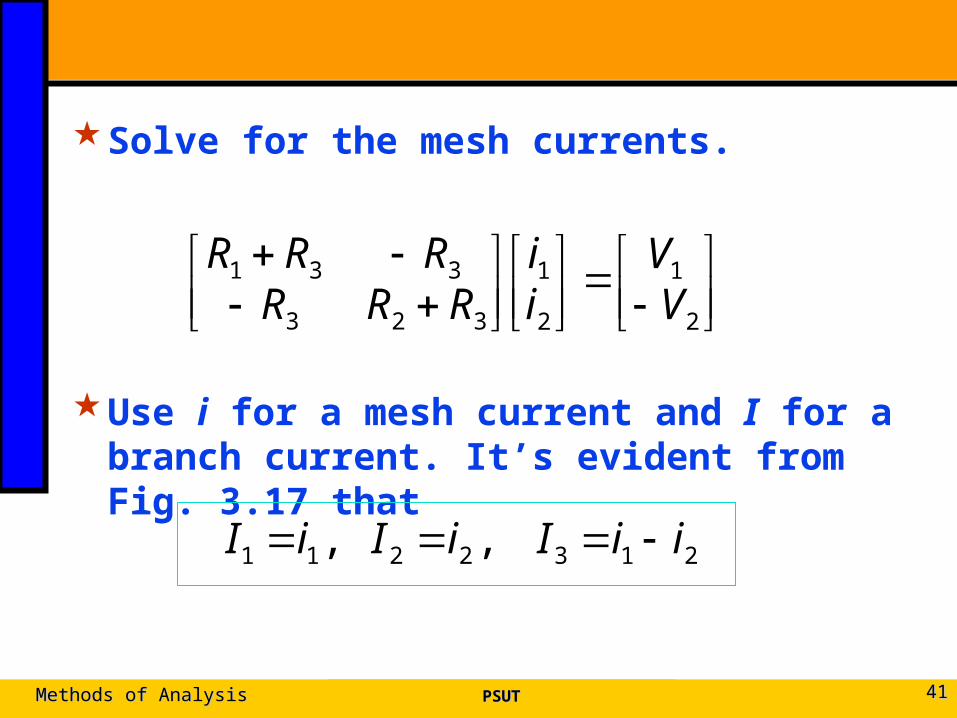
Solve for the mesh currents.
Use i for a mesh current and I for a branch current. It’s evident from Fig. 3.17 that
PSUTPSUTMethods of AnalysisMethods of Analysis 4141
2
1
2
1
323
331
VV
ii
RRRRRR
2132211 , , iiIiIiI
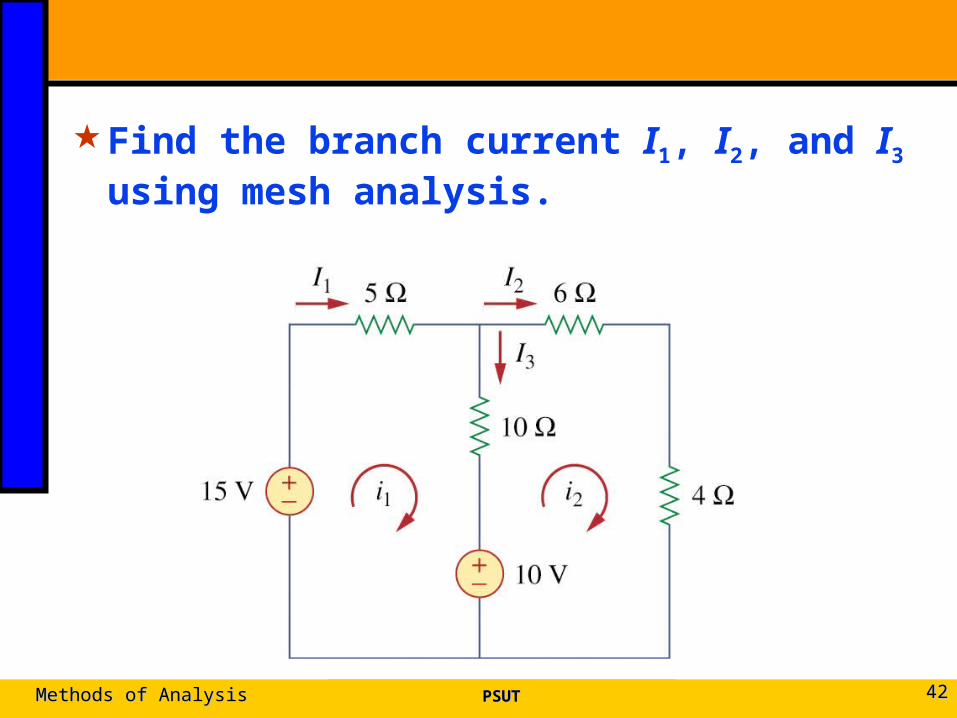
Find the branch current I1, I2, and I3 using mesh analysis.
PSUTPSUTMethods of AnalysisMethods of Analysis 4242
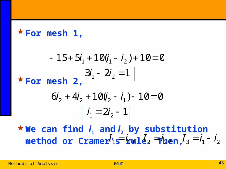
For mesh 1,
For mesh 2,
We can find i1 and i2 by substitution method or Cramer’s rule. Then,
PSUTPSUTMethods of AnalysisMethods of Analysis 4343
123
010)(10515
21
211
ii
iii
12
010)(1046
21
1222
ii
iiii
2132211 , , iiIiIiI
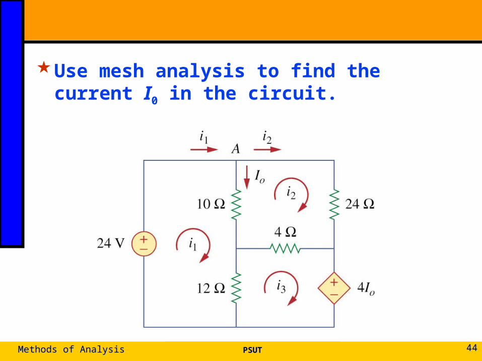
Use mesh analysis to find the current I0 in the circuit.
PSUTPSUTMethods of AnalysisMethods of Analysis 4444
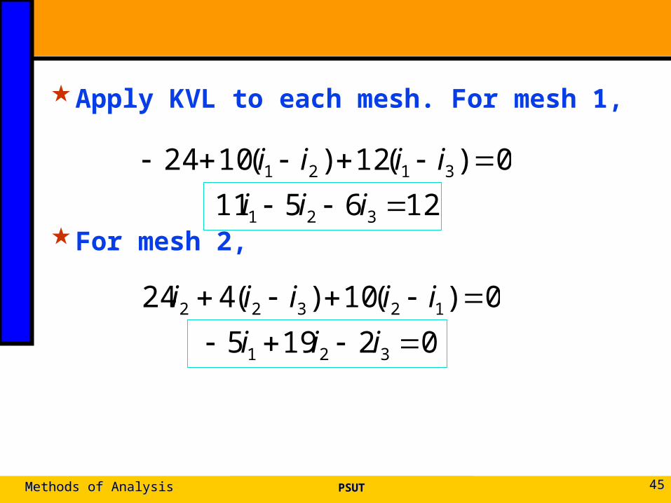
Apply KVL to each mesh. For mesh 1,
For mesh 2,
PSUTPSUTMethods of AnalysisMethods of Analysis 4545
126511
0)(12)(1024
321
3121
iii
iiii
02195
0)(10)(424
321
12322
iii
iiiii
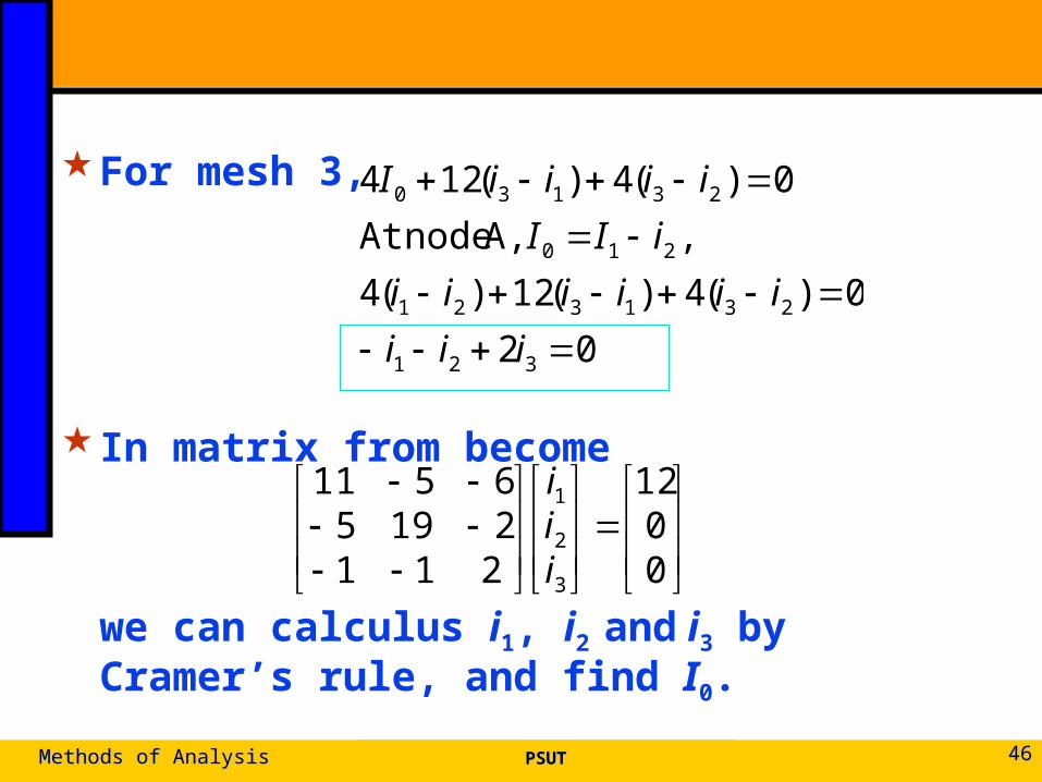
For mesh 3,
In matrix from become
we can calculus i1, i2 and i3 by Cramer’s rule, and find I0.
PSUTPSUTMethods of AnalysisMethods of Analysis 4646
02
0)(4)(12)(4
, A, nodeAt
0)(4)(124
321
231321
210
23130
iii
iiiiii
iII
iiiiI
00
12
21121956511
3
2
1
iii
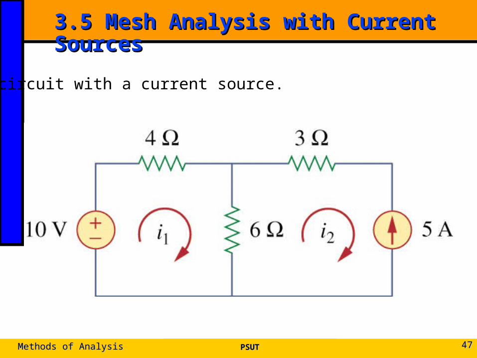
3.5 Mesh Analysis with Current Sources 3.5 Mesh Analysis with Current Sources
PSUTPSUTMethods of AnalysisMethods of Analysis 4747
A circuit with a current source.
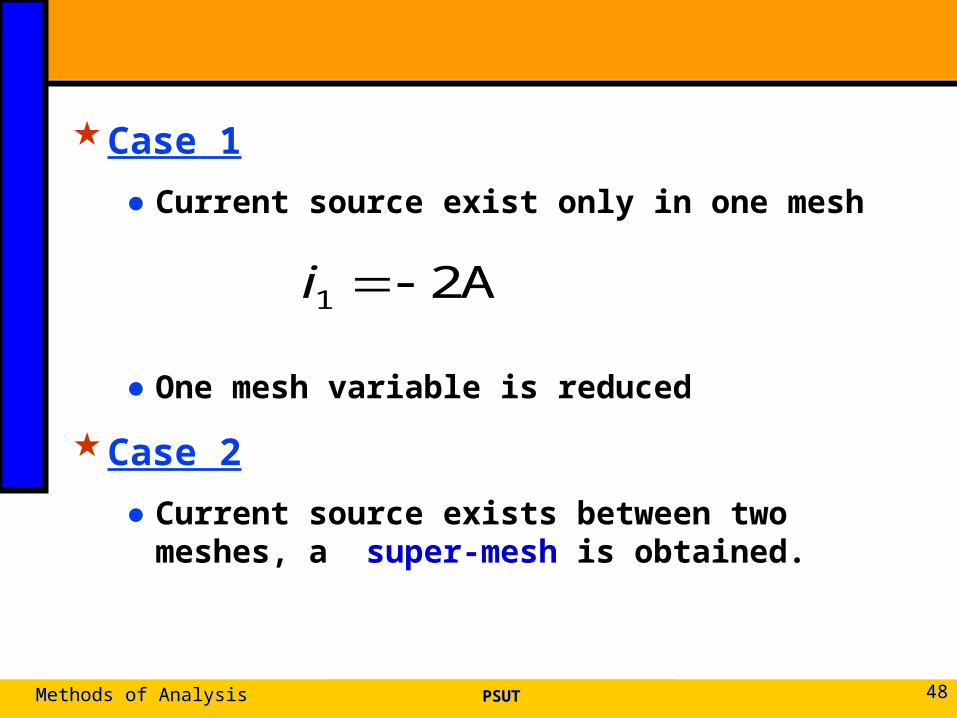
Case 1
● Current source exist only in one mesh
● One mesh variable is reduced
Case 2
● Current source exists between two meshes, a super-mesh is obtained.
PSUTPSUTMethods of AnalysisMethods of Analysis 4848
A21 i
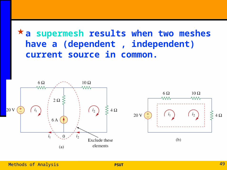
a supermesh results when two meshes have a (dependent , independent) current source in common.
PSUTPSUTMethods of AnalysisMethods of Analysis 4949
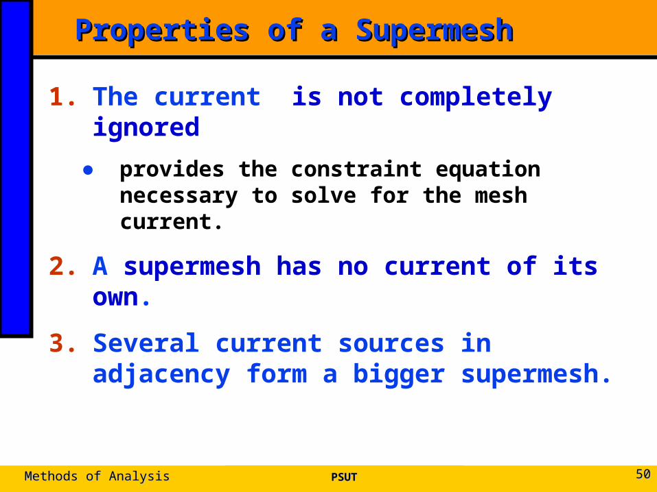
Properties of a SupermeshProperties of a Supermesh
1. The current is not completely ignored
● provides the constraint equation necessary to solve for the mesh current.
2. A supermesh has no current of its own.
3. Several current sources in adjacency form a bigger supermesh.
PSUTPSUTMethods of AnalysisMethods of Analysis 5050
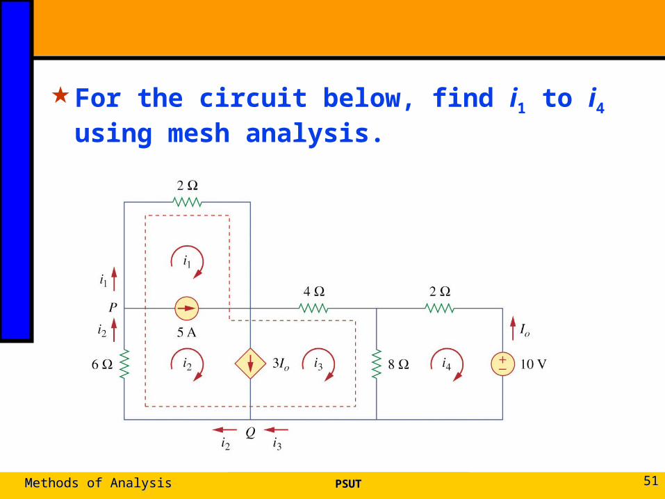
For the circuit below, find i1 to i4 using mesh analysis.
PSUTPSUTMethods of AnalysisMethods of Analysis 5151
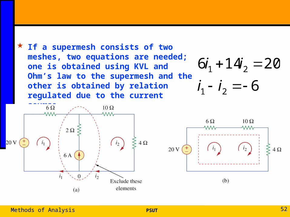
If a supermesh consists of two meshes, two equations are needed; one is obtained using KVL and Ohm’s law to the supermesh and the other is obtained by relation regulated due to the current source. 6
20146
21
21
ii
ii
PSUTPSUTMethods of AnalysisMethods of Analysis 5252
Similarly, a supermesh formed from three meshes needs three equations: one is from the supermesh and the other two equations are obtained from the two current sources.
PSUTPSUTMethods of AnalysisMethods of Analysis 5353
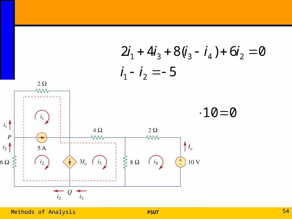
0102)(8
5
06)(842
443
432
21
24331
iii
iii
ii
iiiii
PSUTPSUTMethods of AnalysisMethods of Analysis 5454
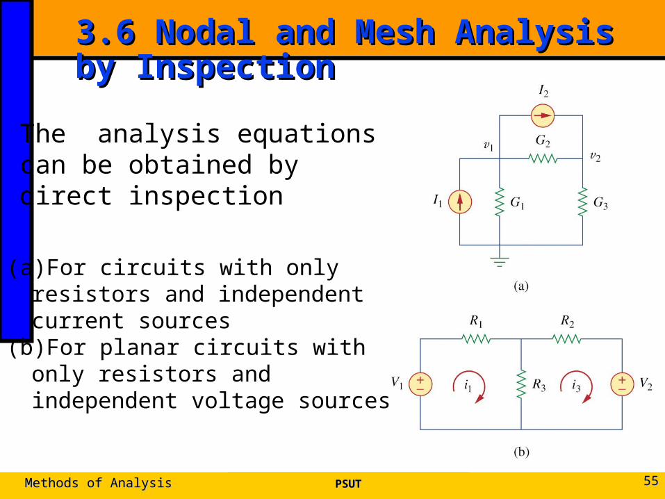
3.6 Nodal and Mesh Analysis by 3.6 Nodal and Mesh Analysis by Inspection Inspection
PSUTPSUTMethods of AnalysisMethods of Analysis 5555
(a)For circuits with only resistors and independent current sources
(b)For planar circuits with only resistors and independent voltage sources
The analysis equations can be obtained by direct inspection
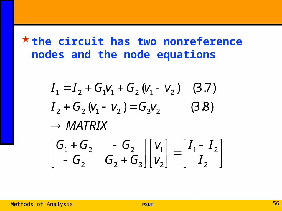
the circuit has two nonreference nodes and the node equations
PSUTPSUTMethods of AnalysisMethods of Analysis 5656
2
21
2
1
322
221
232122
2121121
)8.3()(
)7.3()(
III
vv
GGGGGG
MATRIX
vGvvGI
vvGvGII
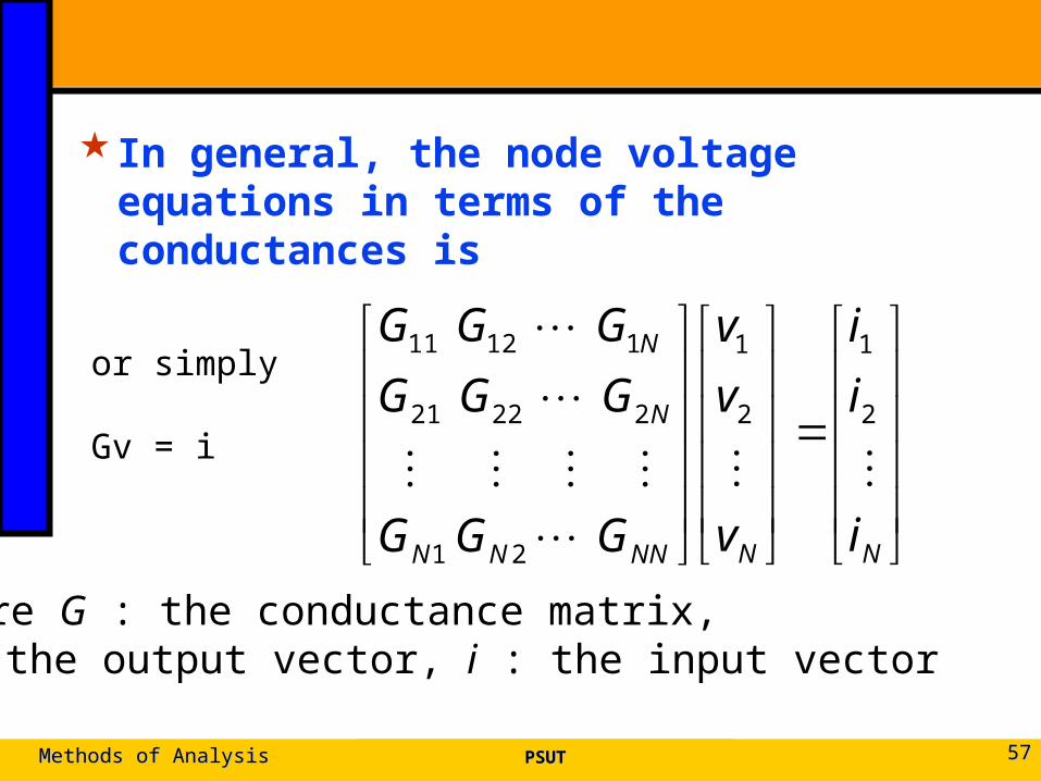
In general, the node voltage equations in terms of the conductances is
PSUTPSUTMethods of AnalysisMethods of Analysis 5757
NNNNNN
N
N
i
i
i
v
v
v
GGG
GGG
GGG
2
1
2
1
21
22221
11211or simply
Gv = i
where G : the conductance matrix, v : the output vector, i : the input vector
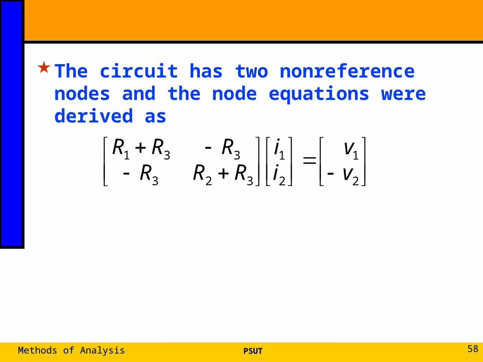
The circuit has two nonreference nodes and the node equations were derived as
PSUTPSUTMethods of AnalysisMethods of Analysis 5858
2
1
2
1
323
331 vv
ii
RRRRRR
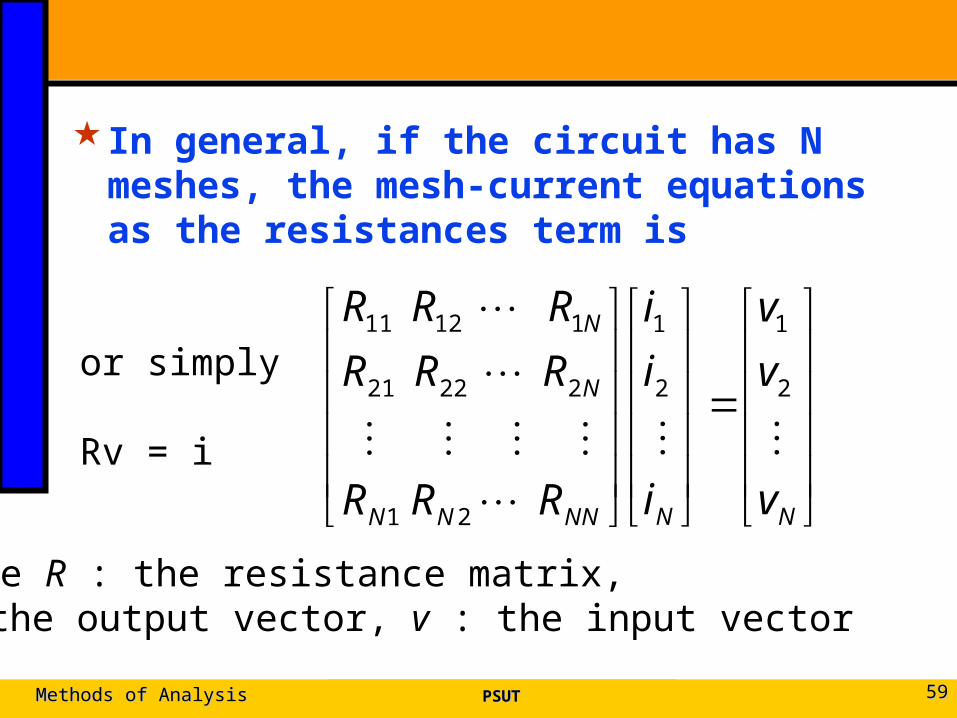
In general, if the circuit has N meshes, the mesh-current equations as the resistances term is
PSUTPSUTMethods of AnalysisMethods of Analysis 5959
NNNNNN
N
N
v
v
v
i
i
i
RRR
RRR
RRR
2
1
2
1
21
22221
11211
or simply
Rv = i
where R : the resistance matrix, i : the output vector, v : the input vector
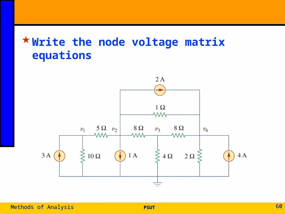
Write the node voltage matrix equations
PSUTPSUTMethods of AnalysisMethods of Analysis 6060
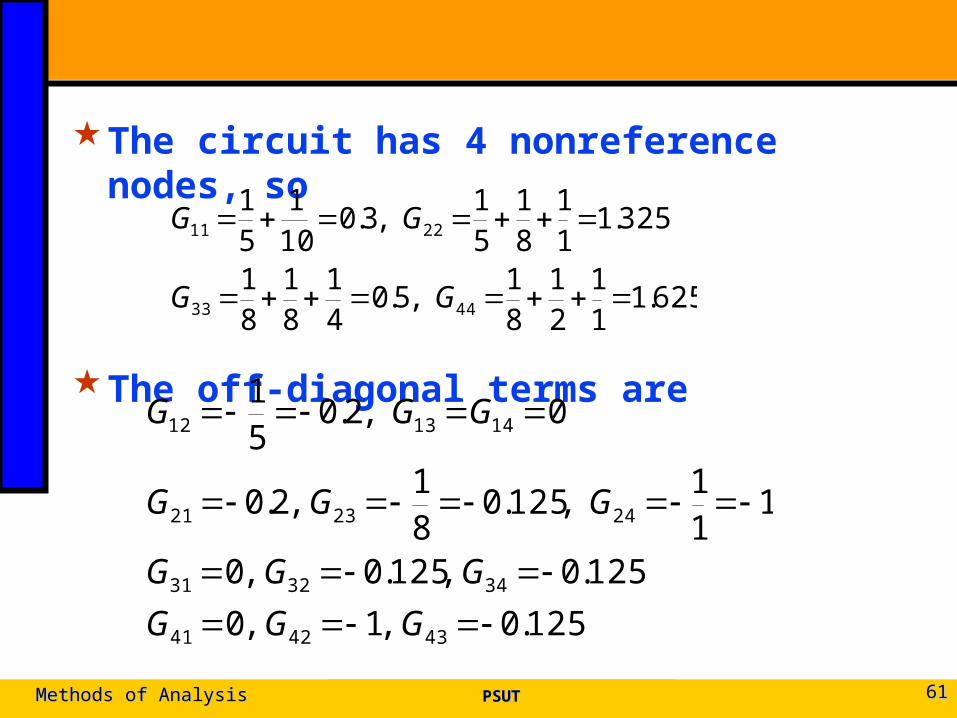
The circuit has 4 nonreference nodes, so
The off-diagonal terms are
PSUTPSUTMethods of AnalysisMethods of Analysis 6161
625.111
21
81
,5.041
81
81
325.111
81
51
,3.0101
51
4433
2211
GG
GG
125.0 ,1 ,0
125.0 ,125.0 ,0
111
,125.081
,2.0
0 ,2.051
434241
343231
242321
141312
GGG
GGG
GGG
GGG
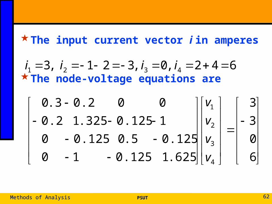
The input current vector i in amperes
The node-voltage equations are
PSUTPSUTMethods of AnalysisMethods of Analysis 6262
642 ,0 ,321 ,3 4321 iiii
6
0
3
3
.6251 0.125 1 0
0.125 .50 0.125 0
1 0.125 .3251 0.2
0 0 0.2 .30
4
3
2
1
v
v
v
v
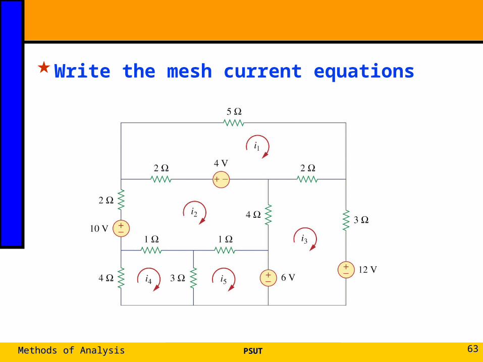
Write the mesh current equations
PSUTPSUTMethods of AnalysisMethods of Analysis 6363
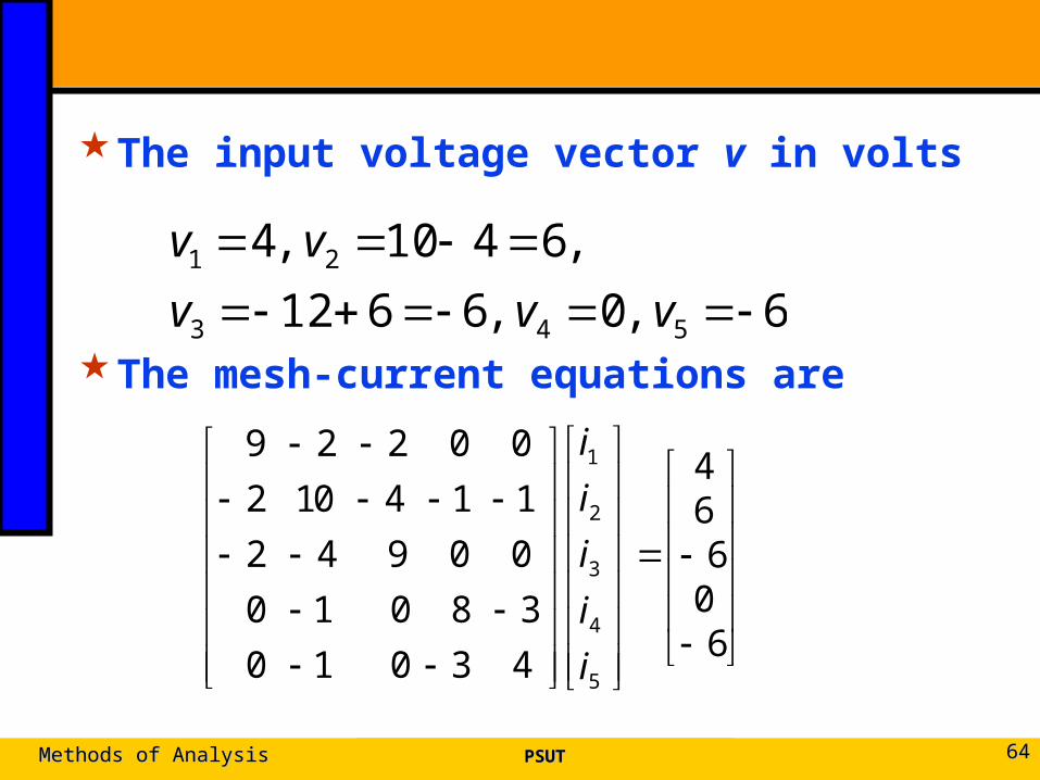
The input voltage vector v in volts
The mesh-current equations are
PSUTPSUTMethods of AnalysisMethods of Analysis 6464
6 ,0 ,6612
,6410 ,4
543
21
vvv
vv
606
64
4 3 0 1 0
3 8 0 1 0
0 0 9 4 2
1 1 4 01 2
0 0 2 2 9
5
4
3
2
1
i
i
i
i
i
3.7 Nodal Versus Mesh Analysis3.7 Nodal Versus Mesh Analysis
Both nodal and mesh analyses provide a systematic way of analyzing a complex network.
The choice of the better method dictated by two factors.
● First factor : nature of the particular network. The key is to select the method that results in the smaller number of equations.
● Second factor : information required.
PSUTPSUTMethods of AnalysisMethods of Analysis 6565
3.10 Summery3.10 Summery
1. Nodal analysis: the application of KCL at the nonreference nodes
● A circuit has fewer node equations
2. A supernode: two nonreference nodes
3. Mesh analysis: the application of KVL
● A circuit has fewer mesh equations
4. A supermesh: two meshes
PSUTPSUTMethods of AnalysisMethods of Analysis 6666