Embed Size (px)
Citation preview
M E T H O D S OF RATING DIESEL FUELS
P. H. SCHWEITZER
School of Engineering, The Pennsylvania State College, State College, Pennsylvania
I. Mechanism of the Diesel Combustion K n o c k
The Diesel process is frequently described as injecting liquid fuel into highly heated air, the fuel igniting instantly upon its entrance into the cylinder. If this description were accurate, there would be no combustion kncck in Diesel engines, generally speaking. The introduction of the fuel into the cylinder is a gradual prceess, if for no other than mechanical reasons. The injection extends over a period of 20 to 35 crank degrees, sometimes more, seldom less. During this period the introduction of the fuel is more or less uniform. If the ignition were instantaneous, the rate of pressure rise would follow the rate of injection and be moderate. Combustion knock, on the other hand, always is accompanied by a very rapid pressure rise.
However, the process described is upset by the ignition lag. The fuel injected does not ignite instantancou ly. The significance of the delay period is discussed in another paper 9 of this symposirm. For us it will suffice to say that the longer the delay the more violent the subsequent ignition and the more severe the combustion knock.
Almost every factor that causes a spark- ignition engine to kncck makes the compression- ignition engine run more smoothly. 45 In both eases the kncek is caused by the autoignition of a ecnsiderablc porticn of the charge, but ~hile in a spark-ignition engine it is ordinarily the last portion of the charge ~hieh autoignites, in the compression-ignition engine combustion is initi- ated by autoignition. This explains the different behavior of the two types of engines.
Consequently fuels of paraffinic base, con- sisting mostly of saturated straight-chain hydro- carbons, are the smoothest and most desirable fuels for Diesel engines, x~hile cracked fuels and also straight-run aromatics burn roughly, benzene being about the worst of all. Gasoline antiknceks have the reverse effect in Diesels/a ~xhile pro- knceks, consisting mostly of mild detonants like ethyl nitrate, added even in a small percentage reduce the Diesel knock remarkably. This is explained by the fact that paraffin fuels and ethyl nitrate ignite after a comparatively short delay and do not permit the accumulation of a considerable amount of combustible charge in the cylinder.
II. History of Diesel Fuel Testing
Rieppel, 43 in 1907, as one of the earliest re- search workers on the behavior of liquid fuels in eompression-ignition engines, recognized that no relation existed between the flash point or burn- ing point of a fuel and its ability to ignite spon- taneously inside an engine cylinder.
Holm} 3 in 1913, investigated autoignition temperatures in oxygen by allowing oil globules to drop to a porcelain crucible cover heated inside a vertical tube furnace swept through by a stream of oxygen.
Constam and 8chlaepfer 13 continued the investigation a ith increased accuracy, but they could not share Helm's opinion that the spon- taneous ignition temperature was of decisive influence on the suitability of fuel oils for Diesel engines.
A simple and successful autoignition tem- perature tester operating with air under atmos- pheric pressure was developed by Moore :'6 in 1919, which has been perfected by Wollers and Ehmcke in the Krupp laboratories? I In Jentseh's modifeatien of the open crucible, the oxygen feed is closely controlled.
Compressed air in a bomb was used by Tausz and h'chulte 5~ and atomization of the fuel added by Hawkes 16 Neumann, ~9 Foord, '5 Holfelderf ~ and Miehailovra. ~a These investigations have sho~n that self-ignition temperature depends to an enormous degree on the delay period and to an appreciable degree on the air pressure, density, air-fuel ratio, material of the errcible, and atomization of the fuel. By agitating the air in the bomb Neumann ''9 obtained self-ignition tem- peratures that were much higher than those for stagnant air, exeept for very short ignition lags, when the reverse was true.
The above investigations rated Diesel fuels in some~hat similar order and have shown that paraffinic fuels have lower self-ignition tem- peratures than aromatic or naphthenie fuels. But the order of magnitude of the time lag in simple bomb tests was a multiple of 0.1 see, compared to a few thousandths of a second obtained in compression-ignition engines. In recently constructed bombs, however, using high pressure, turbulence, and fuel atomization, ignition lags were measured aa that are comparable with those obtained in engines.
In 1923, Hesselman TM described a method for measuring ignition lag, which he used on his
313
314 M E T H O D S OF :RATING D I E S E L F U E L S
engine. In 1931, Le 1Vfesurier and Stansfield 29 gave results of tests to determine the difference in behavior of a wide range of fuels in several compression-ignition engines, and showed that, in any given engine, the combustion knock was broadly related to the delay which occurred between the moment of injection and the be- ginning of rapid pressure rise, which they meas- ured essentially in the same way as Hesselman. Different engines seemed to have only slightly different relative effects on the fuels tested.
In the same year Boerlage and Broeze 6 pub- lished their results on an engine-test method of rating Diesel fuels. The tests were made in a relatively slow speed engine by the throttling method, and each fuel was rated in terms of the blend of cetene and mesitylene which matched it in ignition lag. The tests have shown surprisingly good correlations, indicating not only that the method is dependable but also that differences between engines and running conditions were of relatively slight effect upon the rating.
In January 1932, Pope and Murdock 4~ reported on their tests made with a modified C.F.R. knock-testing engine. In these tests the engine was of the variable compression type, and the rating was based on the lowest compression ratio at which the samples of fuel would just ignite under controlled temperature conditions. While running the engine under such borderline con- ditions did not prove practical, with a "motored engine" the critical compression ratio method gave very useful results.
In July 1932, Boerlage and Broeze 7 proposed that ratings in ignition quality be made in terms of "eetene numbers", using cetene and alpha- methylnaphthalene as primary standard. In 1935 the A.S.T.M.' replaced cetene in this country by cetane for a standard reference fuel of high ignition quality.
Until recently, ignition lag determinations were made from indicator diagrams. In 1932, Boerlage and Broeze 7 described an inertia lag meter, and a year later s reported cetene ratings performed with a modified Midgley type bouncing pin. The "knoekmeter delay method" which has been most widely used in this country is an outgrowth of this method, and was developed by Rende141 in cooperation with the Waukesha Motor Com- pany, the builders of the converted C.F.R. engine which has been tentatively adopted for Diesel fuel rating.
In 1933, Schweitzer, Dickinson, and Reed 46 proposed the use of a predetermined ignition lag, to be obtained by a corresponding adjustment of the compression ratio, for rating. In 1935, Hetzel and Sehweitzer 2~ replaced the bouncing pin by a magnetic pick-up, which flashed the neon lamp of a protractor through an electronic relay.
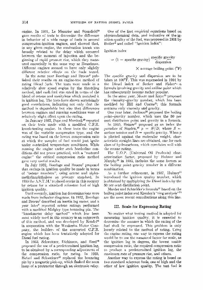
One of the first empirical equations based on physicochemical data, and indicative of the ig- nition quality of the fuel, was proposed in 1931 by Butler I' and called "Ignition index":
Ignition index
= (1 -- specific gravity) specific gravity dispersion
X average boiling point (~
The specific gravity and dispersion are to be taken at 100~ This was superseded in 1934 by the Diesel index of Becker and Fisher4--a formula involving gravity and aniline point which has subsequently become rather popular.
In the same year, Moore and Kaye 35 proposed the viscosity-gravity number, which has been modified by Hill and Coates2~; this formula contains only viscosity and gravity.
One year later, Jackson 26 proposed the boiling point-gravity number, which uses the 50 per cent distillation point and gravity in a formula.
In 1935, Heinze 17 proposed as an index the parachor of Sugden, 49 p = SLID, where S -~ surface tension and D = specific gravity. When p is plotted against the molecular weight, char- acteristic straight lines are obtained, one for each class of hydrocarbons, which correlates well with the cetane rating.
The U.O.P. (Universal Oil Products) char- acterization factor, proposed by Hubner and Murphy 25 in 1935, includes the same factors as the boiling point-gravity number in a different combination.
As a further refinement, in 1937, Hubner ~~ introduced the ignition quality nmnber, which is obtained by multiplying the Diesel index by the 50 per cent distillation point.
Marder and Schneider's formula ~2 based on the boiling point index and Kreulen's "ring analysis ' ':s are the most recent contributions along this line.
III. Scale for Expressing Rating
No matter what testing method is adopted for measuring ignition quality, it is essential to determine the manner in which the rating of the fuel shall be expressed. This problem is only loosely related to the method of rating. Using the engine rating, one way to express the rating would be to use the measured factor for scale, as the ignition lag in degrees, the lowest usable compression ratio, the required compression ratio to produce a predetermined ignition lag, the maximum rate of pressure rise, and others.
Another way to express the rating is based on two standard reference fuels, one of high and the other of low ignition quality. The test fuel is

M ETHODS OF R A T I N G D I E S E L F U E L S 315
matched with a blend of the two reference fuels mixed in such proportion that its ignition quality (in the arbitrary scale of the test) is equal to that of the reference blend. The rating of the fuel is then expressed as the percentage concentration of the reference fuel of high quality.
This second method can be used with any testing method that may be adopted--bomb, physieochemieal, or engine tes ts - -and it offers certain distinct advantages. Rating expressed in a reference fuel scale is no doubt, less affected by the instrument factors. But the deciding con- sideration in the adoption of the cetene (later eetane) scale was the preceding experience with gasoline knock rating. In the early period that was expressed by Rieardo's H.U.C.R. (highest useful compression ratio), but that gave way first to the toluene equivalent and later to the octane number. Technologists accustomed to the octane number were quick to adopt the eetene number when it was proposed by Boerlage and Broeze.
The selection of the reference fuels required, however, a careful study. For reproducibility they should be pure substances of a known chemical composition, which are stable in storage. For range they should possess higher and lower ignition quality, respectively, than any fuel to be tested. For validity they should possess a chemical constitution and physical properties (viscosity and volatility) not much different from those of the normal fuels. Finally, they should be available at a reasonable price.
TABLE I
Properties of cetane and alpha-methylnaphthalene
Properties Cetane*
Alpha- methyl-
naphtha- lene~
Specific gravity 60/60 ~ 0.778 1.018 Flash point, closed cup, ~ 230+ 214 Pour point, ~ +65 +50 Viscosity, SSU at 100 ~ 38 37 Distillation range, ~
Initial boiling point 516 450 10 per cent 532 456 50 per cent 534 438 90 per cent 536 460
End point 543 482 Aniline point, ~ 204.0 Miscible
* As supplied by E. I. du Pont de Nemours and Company.
As supplied by Reilly Tar and Chemical Company.
The reference fuels which were adopted by the A.S.T.M. as most satisfying these requirements are cetane, C16H.~, and alpha-methylnaphthalene, Cull10. The properties of these substances are given in Table I.
Table I shows that the properties of these hydrocarbons are in line with those petroleum fuels which are used most in high-speed com- pression-ignition engines. The ignition quality of cetane is about equal to that of cetene, C16H~2, but it is claimed that it is more stable in storage.
Since June, 1935, when the A.S.T.M. recom- mended its use, the cetane scale has become practically universal in this country as a measure of ignition quality. In Europe the use of the cetene number scale has been continued to date.
IV. Three Groups of Test Methods
A. Bomb Tests
The primary objective with the crucible and bomb tests was to determine the self-ignition temperature of the fuel. I t has been observed that fuels of high self-ignition temperature either fail to ignite at all in the engine, or if they do ignite there is a long delay with a corresponding combustion knock. So self-ignition temperature was taken for a measure of ignition quality. The Moore apparatus uses an open porcelain crucible heated in a furnace or solder bath into which drops of oil are admitted while the temperature of the crucible is raised by small increments until the fuel autoignites. This method was simple and well adapted to laboratory practice. I t was found, 4-6,29 however, that the self-ignition tem- peratures obtained with such an apparatus lie too close together and, furthermore, they do not rate fuels in the same order as their engine behavior. This should not surprise us, if we realize that temperature is just one of the many factors that determine autoignition. Others are chamber pressure, air motion, fuel drop size, fuel-air ratio, and tinle lag of ignition. Bridgeman and Marvin TM have shown that even the size and material of the crucible influenced the self- ignition temperature.
Subsequent efforts have been directed at creating conditions in an ignition bomb similar to those in the engine, and improved ignition testers have been evolved. Such recent variants as Holfelder's 22 and Michailovra's 33 inject finely atomized sprays into heated dense air, agitated to simulate turbulence, and measure the delay of the ignition. The results obtained are comparable to and correlate well with engine tests. By the time the bomb has reached this perfection it has become so complicated that it now offers no
316 M E T H O D S OF R A T I N G D I E S E L F U E L S
advantage either in first cost or in ease of oper- ation over the test engine.
The ideal that self-ignition temperature as a characteristic property of the fuel would deter- mine its ignition behavior did not materialize. Whether or not a fuel drop ignites at a certain temperature depends a great deal on how long the drop is exposed to that temperature and, furthermore, the time sensitivities of the various fuels are different. The determination of the maximum or minimum ignition temperatures, which correspond to zero or infinite time lags, respectively, is of theoretical interest, but the existence of neither of them has yet been proved.
B. Engine Tests
The success of the gasoline knock-testing engine encouraged the search for a method that looks for an answer on Diesel fuel quality in the engine itself. The possibility of using tim gasoline knock-testing engine unaltered suggested itself. From the reverse behavior of the fuel in spark- ignition and compression-ignition engines it was not unreasonable to expect that Diesel fu31s would rank in the reverse order as their octane numbers or directly as their "heptane numbers". One practical drawback to this method has been the difficulty of carbureting heavy oils and the trouble these oils cause in the engine by gumming, coking, crankcase dilution, etc. Dumanois 14 overcame these difficulties by mixing 15 per cent Diesel fuel with reference gasoline. The knock
rating of such mixtures in the gasoline knock- testing engine was fot:nd to correlate fairly well with the behavior of the heavy oil in the Diesel engine. But at the same time the tests have shown 25 that it is too mt:ch to hope for a perfect reciprocity in a spark-ignition and compression- ignition engine that would justify the universal adoption of the gasoline-testing method for Diesel fuels. If a larger margin of error is ad- missible this simple method of rating Diesel fuels is recommended.
There is no apparatus that simulates the compression-ignition engine conditions as much as a compression-ignition engine itself. The use of a compression-ignition engine for testing the ignition quality of fuels started in 1931 and attained considerable momentum recently. A variety of methods have been used by Le Mesurier and Stansfield, 29 Boer]age and Broeze, ~ Pope and Murdcck, ~~ Joachim, 2~ Rendel, 41 and Schweitzer and Hetzel. 47 In principle, however, all of these agreed. The ignition quality as svch is not measured by any engine test, but is only deter- mined indirectly on the basis of the behavior of the fuel in the test engine in regard to svch characteristics as combustion knock, ignition lag, rate of pressure rise, starting, or misfiring.
A valid objection to engine test methods is that the results they give have no theoretical significance, and cannot be expressed in terms of ordinary physical units. However, in view of the great practical significance of fuel rating, this
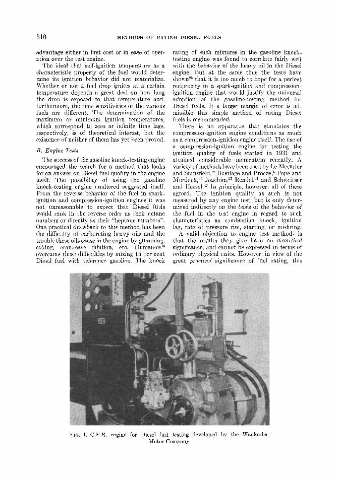
FIG. 1. C.F.R. engine for Diesel fuel testing developed by the Waukesha Motor Company
M E T H O D S OF R A T I N G D I E S E L F U E L S 3 1 ~
! i
, ' / / / * * f / / Z J J . E
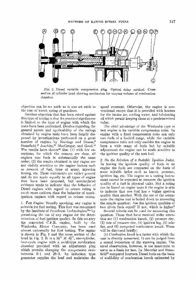
FIG. 2. Diesel variable compression plug. Optical delay method. Cross section of cylinder head showing mechanism for varying volume of combustion chamber.
objection can be set aside as it was set aside in the case of kneek rating of gasolines.
Another objection that has been raised against this type of testing is that Rs practical significance is limited to the type of engine with which the tests have been performed. Doubts regarding the general nature and applicability of the ratings obtained by engine tests have been largely dis- persed by investigations performed on a great number of engines by Boerlage and Broeze, 6 Stansfield, 4s Joachim, 27 MacGregor, and Good. a1 The results have shown 46 that (1) with few ex- ceptions, for which the reasons are clear, all engines rate fuels in substantially the same order; (2) the results obtained in any engine are not unduly sensitive to the engine factors such as amount of fuel, type of spray, injection timing, etc. These statements are rather general and do not apply equally to all types of engine that have been proposed, but accumulated evidence tends to indicate that the behavior of Diesel engines with regard to cetane rating is much more uniform than the bahavior of spark- ignition engines with regard to octane rating.
1. Test Engine. Broadly speaking, any engine is suitable for fuel testing. This fact was recognized by the Institute of Petroleum Technologists 2~ by permitting the use of any engine for the deter- mination of fuel ignition quality. In this country the converted C.F.R. engine, built by the Waukesha Motor Company, has been used almost universally for fuel testing. The engine is shown in Fig. 1 and the cross section of the
31' ' 4�88 head in Fig. 2. It is a ~ )< one-cylinder, four-cycle engine with a swirl-type combustion chamber provided with an adjustment plug which permits changing the compression ratio between 6:1 and 28:1. An induction type generator supplies the load and maintains the
speed constant. Otherwise, the engine is con- ventional except that it is provided with heaters for the intake air, cooling water, and lubricating oil which permit keeping these at a predetermined value.
The chief advantage of the Waukesha type of test engine is its variable compression ratio. An engine with a fixed compression ratio can only test fuels of a limited range, while the variable compression ratio not only enables the engine to burn a wide range of fuels but by suitable adjustment the engine can be made sensitive to the ignition quality of the test fuel.
2. On the Selection of a Suitable Ignition Index. In testing the ignition quality of fuels in an engine the fuels are compared on the basis of some suitable index such as knock, pressure, ignition lag, etc. The engine as a testing instru- ment cannot be expected to measure the ignition quality of a fuel in physical units. But a rating can be based on engine tests if the engine is able to indicate that one fuel has a higher ignition quality than another. With the use of the cetane scale the engine test is boiled down to answering the simple question: Are the ignition qualities of two given fuels equal? If not, which is higher?
Several criteria can be used for answering this question. Those that have received wider atten- tion are (1) combustion knock, (2) pressure rise, (3) rate of pressure rise, (4) ignition lag, (5) mis- fire, and (6) computed combustion knock. These will be discussed briefly:
(1) Combustion knock is a factor with which the user is directly concerned. I t can be judged from a casual inspection of the running engine. The aural observation, however, is too inaccurate to serve as a basis for test. Le Mesurier and Stans- field 29 compared fourteen Diesel fuels on the basis of audibility of combustion knock estimated by
318 M E T H O D S OF R A T I N G D I E S E L F U E L S
ear. In the Junkers engine, which had an integral combustion chamber, the comparative rating of the fuels was the same at any speed between 300 and 1000 rpm. On the other hand, in the Mc- Laren-Benz engine, which is of the precom- bustion chamber type, the order of merit changed with the speed.
Another difficulty with audibility tests is that it is not always easy to discriminate between combustion knock and other engine noises. To eliminate the latter difficulty and also the personal element in sound estimation, Car- penter and Stansfleld l~ developed the strobo- phonometer, which measures the noise of a certain phase of the cycle by means of a mechan- ically driven selector and a suitable microphone. The noise readings obtained with this instrument correlated fairly well with ignition lag measure- ments and rate of pressure rise measurements.
(2) Pressure rise is frequently used as a measure of engine roughness. The maximum explosion pressure cannot be used as a measure of roughness, 6 because an increase in intake air pressure increases the maximum pressure but at the same time makes the engine run more smoothly. I t was also observed that the effect of fuel on the maximum pressure is indefinite. Good, bad, and indifferent fuels sometimes happen to have about the same combustion pressure rise. For these reasons pressure has never been considered as a suitable index of ignition quality.
(3) Rate of pressure rise is defined as the deriv- ative of the pressure on the basis of time or crank angle. I t is an indirect measure of the rapidity of burning. I t was observed that com- bustion knock is always accompanied by a rapid rate of pressure rise. The correlation between shock audibility and maximum rate of pressure rise was found to be about 90 per cent. 29,45 The correlation between ignition lag and maximum rate of pressure rise was equally high.
In early investigations maximum rate of pressure rise was determined by drawing tan- gents to crank angle base indicator cards. The observation was made that if the M.R.P.R. (maximum rate of pressure rise) is less than 30 psi per degree of crank motion, the operation is smooth. The engine is liable to knock if the M.R.P.R. is above 50 lb. per degree and is almost certain to knock if the rise exceeds 100 lb. per degree crank angle.
At present instruments are available which give the maximum rate of pressure rise directly, instead of deriving it from a pressure curve. By using an electromagnetic pick-up in connection with a diaphragm in the cylinder head, the flexing of the diaphragm which follows the pressure generates voltage in proportion to the
flexing (flux-cutting) velocity. This voltage can be impressed on a cathode ray oscillograph and the M.R.P.R. scaled as the maximum deflection of the light point on the screen.
The Sunbury knock indicator, 3 which has been introduced recently for knock rating gasolines, is using this principle. Here, the magnified output of the magnetic pick-up is fed into a damped millivoltmeter and the reading is a measure of the average rate of pressure rise. The use of this instrument for Diesel fuel testing deserves serious consideration.
(4) Ignition lag is the time interval between the point of injection and the point of ignition. I t has been used as the preferred index of ignition quality since the investigations of Le Mesurier and Stansfield 29 and of Boerlage and Broeze 6 have established the close relations that exist between ignition lag and fuel quality as evi- denced by combustion knock and difficulty of starting. The shorter tile ignition lag of the fuel, the more quietly the engine runs and the more easily it starts if other conditions are the same. The principle of most current methods of meas- uring ignition quality is to match the sample fuel with a reference fuel which has the same ignition lag in a standard test engine under standard operating conditions or in the user's engine under the user's normal operating conditions.
The ease with which the ignition lag can be measured was no doubt a factor in its adoption for testing. In spring-loaded nozzles the be- ginning of the injection coincides with the beginning of the valve lift and can be deter- mined very accurately by electrical means if the valve stem is accessible, as it usually is. The ignition point, on the other hand, was obtained from the indicator card, which regularly shows a readily noticeable pressure rise where ignition sets in.
While in most cases the determination of the
i
!
!
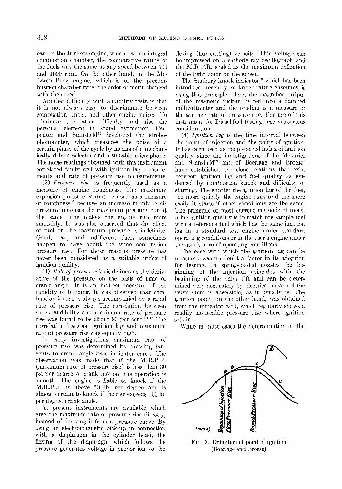
FIG. 3. Definition of point of ignition (Boerlage and Broeze)
M E T H O D S OF R A T I N G D I E S E L F U E L S 319
ignition point from the indicator diagram offers no difficulty, in cases like that shown in Fig. 3, a more exact definition is needed. Ignition point is frequently defined as the point where the pres- sure rises above the compression pressure (Point b, Fig. 3). Boerlage and Broeze 6 are of the opinion, however, that the ignition point so defined is not significant of the knock or of the ignition quality of the fuel. They advocate the use of the first appreciable pressure rise (Point c, Fig. 3) as ignition point. HetzeP 9 has, in fact,, shown by oseillograms that by successively decreasing the compression ratio the point of appreciable pressure rise occurred later and later while the point of initial pressure rise was the same. Ignition point has also been variously defined as the time of first flame formation as detected by the human eye on a photographic film 22 or by a photocell, 44 but for routine testing this is probably still less significant, as incan- descence is of no immediate concern.
For the purpose on hand the definition of Boerlage and Broeze seems the most appropriate, although it is realized that in certain cases it must be arbitrarily decided when the rate becomes "appreciable."
(5) Misfire occurs if the compression ratio is not high enough to cause ignition. Since fuels of low ignition quality misfire at higher compression ratios than fuels of high ignition quality, misfire can and is being used as an index of ignition quality, in using the cetane scale the procedure again consists of matching the sample fuel with a reference fuel which misfires under identical conditions. A misfiring condition may be brought ~bout by various methods. In a running engine one may reduce the compression ratio (if it is a variable compression engine), or decrease the intake air pressure (by throttling), or retard the injection timing, or decrease the jacket water temperature to the point at which misfiring occurs. The other alternative is motoring the
engine with injection shut off until it reaches stable temperature. Then the ignition is turned on. If no ignition takes place the compression ratio (or the other factors) is raised until ignition does take place. The borderline of misfiring is thus determined.
Two methods involving misfiring have become popular for fuel testing. The C.C.R. (critical compression ratio) method 4~ is using a motored engine, and the test is sometimes referred to as the starting test, as it simulates starting con- ditions. The throttling method throttles the intake air of a running engine until the engine misfires. This method sometimes is referred to as the altitude test. Both of these misfiring tests give a high correlation with the ratings ob- tained by the delay methods.
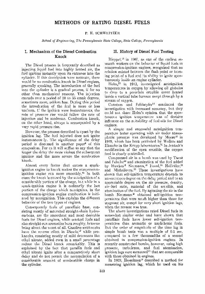
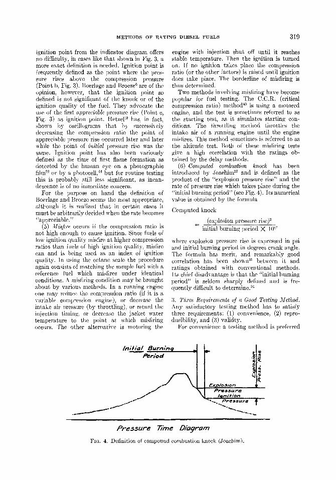
(6) Computed combustion knock has been introduced by Joachim 27 and is defined as the product of the "explosion pressure rise" and the rate of pressure rise which takes place during the "initial burning period" (see Fig. 4). Its numerical value is obtained by the formula
Computed knock
(explosion pressure rise) 2 initial burning period X 10 4'
where explosion pressure rise is expressed in psi and initial burning period in degrees crank angle. [['he formula has merit, and remarkably good correlation has been shown 31 between it and ratings obtained with conventional methods. Its chief disadvantage is that the "initial burning period" is seldom sharply defined and is fre- quently difficult to determine. ~4
3. Three Requirements of a Good Testing Method. Any satisfactory testing method has to satisfy three requirements: (1) convenience, (2) repro- ducibility, and (3) validty.
For convenience a testing method is preferred
I t l i / ] ~ l I 8 u r n ; n q Period
~xp]o.sson P ~ 5 ~ u r 8
Preosure 77mc Z)iagram
FIG. 4. Definition of compound combustion knock (Joachim).
3 2 0 M E T H O D S OF R A T I N G D I E S E L F U E L S
which is quick and simple, and does not require elaborate instrumentation and numerous delicate adjustments.
I t is only a truism that a good testing method should give reproducible results. I t is no less a truism that a properly standardized test cannot but give reproducible re u:ts. The essence of the matter, however, is that it is not desirable or even possible to standardize a great number of factors to an absolute accuracy, with no tolerance permitted�9 If slight variations in some factors cause a great variation in the test result, the re- producibility is poor. The same term is applied if the test result is affected by factors the control of which is difficult or impossible�9 The term "re- producibility" is used in this sense in this dis- cussion.
"VMidity" means that the results of the test are representative and give exactly the infor- mation the observer is seeking. If the observer is interested in the wear resistance of a metal, the Brinell hardness test is valid, but a test of tensile strength is not. I t is not easy to determine the validity of a test on ignition quality, because we have no exact definition of what ignition quality is. I t is generally understood that Diesel fuels of high ignition quality start more easily, run more smoothly, and begin to misfire later than fuels of low ignition quality. But there is no conclusive evidence that these three things mean one and the same thing and, for that matter, we do not even know what any one of them means. The fact that has been established by numerous investigations is this: If by any arbi trary tests a group of fuels is ranged in the order of their resistance to misfire, then in the order of their ease of starting, then in the order of their smooth- ness of running, the three orders will be not exactly, but substantially, the same. I t also has been shown that engines of various types and sizes rate the fuel in substantially the same order. These observations form the justification of the ignition quality testing. But not every test shows equally good correlation. The validity of a testing method will be considered high if its correlation is high with other tests and tests on other engines. The behavior of the fuels in service engines is considered most significant from the standpoint of validity.
To judge the various fuel-testing methods that have been proposed they are to be examined as to the extent to which they satisfy the three basic requirements of convenience, reproduci- bility, and validity. Some of these can be decided even without considering the details of the particular testing technique�9
Tests based on the audible knock have not been used to any extent in routine testing because
they are inconvenient. No simple measuring instrument is available for the purpose.
Tests using the maximum pressure or com- bustion pressure rise for index of ignition quality must be ruled out on the lack of validity�9
Maximum rate of pressure rise, on the other hand, correlates fairly well with valid indices, and the test can be made conveniently with simple instruments. While this type of test has not yet been proposed formally we have given consider- able attention to it. As a result, the author's opinion is that the weakness of the M.R.P.R. test is its poor reproducibility.
For perfect reproducibility the engine and operating conditions have to be standardized with any testing method. But a desirable ignition index is one that is most sensitive to fuel quality and least sensitive to engine factors, particularly to those that are difficult to control.
The more important engine factors arc as follows: engine speed, jacket temperature, inlet air temperature and pressure, compression ratio, combustion chamber shape, injection timing, injected fuel quanti ty (load), and nozzle opening pressure. Of these, injection timing seems to give the most trouble.
On many engines the injection timing can be controlled and read, on some it can be controlled but not read, and on some others it can be neither controlled nor read. Test engines as a rule permit setting the injection point at will, but an error of up to 0.5 ~ can be committed easily. When changing from one fuel to another of different viscosity or gravity, the injection advance angle changes with unchanged injection setting. For these reasons an index of ignition quality which
20"
",4
\
?
o Jo zJ zo i~ 1o j T. C
f~ecti~a Ad~me A~/~, De I r
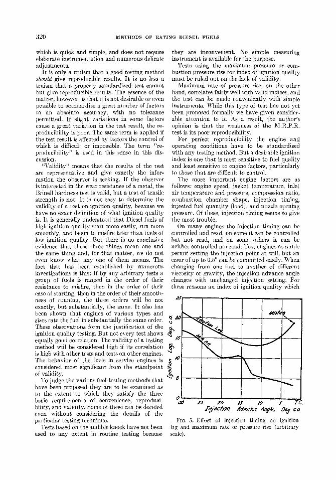
FIG. ,5. Effect of injection timing on ignition lag and maximum rate or pressure rise (arbitrary scale).
M E T H O D S O F R A T I N G D I E S E L F U E L S 321
is not unduly sensitive to injection timing is clearly preferred.
4. Effect of Injection Timing. Injection timing in an engine is controlled ordinarily by the fuel injection pump, but the beginning of pump delivery should not be taken as the beginning of the injection. The actual injection, corresponding to the exit of the first drop of fuel from the spray nozzle, always takes place later, the in- jection lag varying with the injection tube length, engine speed, fuel viscosity, injection quantity, etc. Therefore a fixed pump injection does not mean a constant injection timing. The injection point may vary 5 degrees crank angle or more according to engine speed, fuel viscosity, injection quantity, etc.
The effect of the injection advance angle on the maximum rate of pressure rise is erratic. Figure 5 is an example, where the waved line shows the maximum rate of pressure rise in an arbitrary scale and the heavy line the ignition lag in degrees crank angle. When the injection is advanced from top center to 12 degrees before top center the M.R.P.R. rises, because the combustion approaches constant volume conditions. But at the same time the ignition delay period is also advanced, coming closer and closer to the high temperature zone near top center and becoming shorter and shorter. The shorter ignition lag reduces the amount of vaporized fuel accumulated at the moment of ignition and tends to l ecluce the
\ " / 110
x,, o .,~ 4 0 ,3O gO I0 Zr
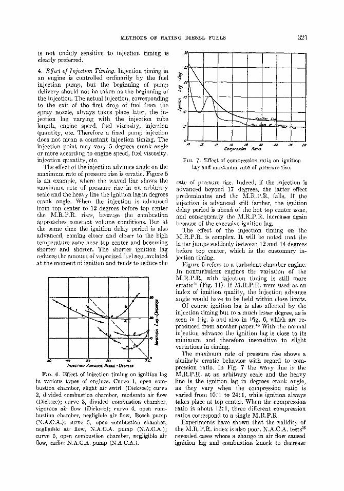
Fro. 6. Effect of injection timing on ignition lag in various types of cngincs. Curve 1, open com- bustion chamber, slight air swirl (Dieksee); curve 2, divided combustion chamber, moderate air flow (Dieksee); curve 3, divided combustion chamber, vigorous air flow (Dieksee); curve 4, open com- bustion chamber, negligible air flow, Bosch pump (N.A.C.A.); curve 5, open combustion chamber, negligible air flow, N.A.C.A. pump (N.A.C.A.); curve 6, open combustion chamber, negligible air flow, earlier N.A.C.A. pump (N.A.C.A.).
Zl
�9 2 . $
.q
.t~
o ~o
\
\
/4 /6 /8 ~0 22 24 ~'G Com/~e~n Ral~
FIG. 7. Effect of compression ratio on ignition la~ and maximum rate of pressure rise�9
rate of pressure rise. Indeed, if the injection is advanced beyond 17 degrees, the latter effect predominates and the M.R.P.R. falls. If the injection is advanced still farther, the ignition delay period is ahead of the hot top center zone, and consequently the M.R.P.R. increases again because of the excessive ignition lag.
The effect of the injection timing on the M.R.P.R. is complex. I t will be noted tnat the latter jumps suddenly between 12 and 14 degrees before top center, which is the customary in- jection timing.
Figure 5 refers to a turbulent chamber engine. In nonturbulent engines the variation of the M.R.P.R. with injection timing is still more erratic 46 (Fig. 11). If M.R.P.R. were used as an index of ignition quality, the injection advance angle would have to be held within close limits.
Of course ignition lag is also affected by the injection timing but to a much lesser degree, as is seen in Fig. 5 and also in Fig. 6, which are re- produced from another paper. 46 With the normal injection advance the ignition lag is close to its minimum and therefore insensitive to slight variations in timing.
The maximum rate of pressure rise shows a similarly erratic behavior with regard to com- pression ratio. In Fig. 7 the wavy line is the M.R.P.R. at an arbitrary scale and the heavy line is the ignition lag in degrees crank angle, as they vary when the compression ratio is varied from 10:1 to 24:1, while ignition always takes place at top center. When the compression ratio is about 12:1, three different compression ratios correspond to a single M.R.P.R.
Experiments have shown that the validity of the M.R.P.R. index is also poor. N.A.C.A. tests as revealec[ cases where a change in air flow caused ignition lag and combustion knock to decrease
322 M E T H O D S OF R A T I N G D I E S E L F U E L S
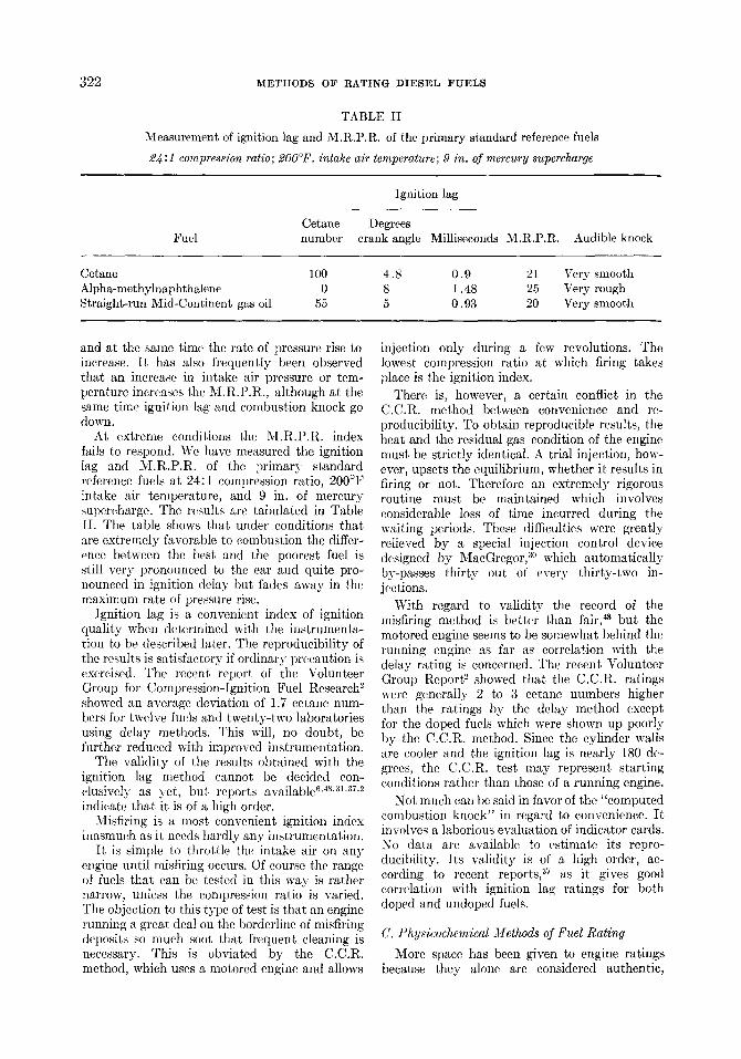
TABLE II
Measurement of ignition lag and M.R.P.R. of the prinmry standard reference fuels
2~ :1 compression ratio; 200~ intake air temperature; 9 in. of mercury supercharge
Ignition lag
Cetane Degrees Fuel number crank angle Milliseconds M.R.P.R. Audible knock
Cetane 100 4.8 0.9 21 Very smooth Alpha-methylnaphthalene 0 8 1.48 25 Very rough Straight-run Mid-Continent gas oil 55 5 0.93 20 Very smooth
and at the same time the rate of pressure rise to increase. I t has also frequently been observed that an increase in intake air pressure or tem- perature increases the M.R.P.R., although at the same time ignition lag and combustion knock go down.
At extreme conditions the M.R.P.R. index fails to respond. We have measured the ignition lag and M.R.P.R. of the primary standard reference fuels at 24:1 compression ratio, 200~ intake air temperature, and 9 in. of mercury supercharge. The results are tabulated in Table II. The table shows that under conditions that are extremely favorable to combustion the differ- ence between the best and the poorest fuel is still very pronounced to the ear and quite pro- nounced in ignition delay but fades away in the maximum rate of pressure rise.
Ignition lag is a convenient index of ignition quality when determined with the instrumenta- tion to be described later. The reproducibility of the results is satisfactory if ordinary precaution is exercised. The recent report of the Volunteer Group for Compression-Ignition Fuel Research 2 showed an average deviation of 1.7 eetane num- bers for twelve fuels and twenty-two laboratories using delay methods. This will, no doubt, be further reduced with improved instrumentation.
The validity of the results obtained with the ignition lag method cannot be decided con- elusively as yet, but, reports available 6,4s,:~l,aT,2 indicate that i t is of a high order.
Misfiring is a most convenient ignition index inasmuch as it needs hardly any instrumentation.
I t is simple to throttle the intake air on any engine until misfiring occurs. Of course the range of fuels that can be tested in this way is rather narrow, unless the compression ratio is varied. The objection to this type of test is that an engine running a great deal on the borderline of misfiring deposits so much soot that frequent cleaning is necessary. This is obviated by the C.C.R. method, which uses a motored engine and allows
injection only during a few revolutions. The lowest compression ratio at which firing takes place is the ignition index.
There is, however, a certain conflict in the C.C.R. method between convenience and re- producibility. To obtain reproducible results, the heat and the residual gas condition of the engine must be strictly identical. A trial injection, how- ever, upsets the equilibrium, whether it results in firing or not. Therefore an extremely rigorous routine must be maintained which involves considerable loss of time incurred during the waiting periods. These difficulties were greatly relieved by a special injection control device designed by MacGregor, a~ which automatically by-passes thir ty out of every thirty-two in- jections.
With regard to validity the record of the misfiring method is better than fair, 4s but the motored engine seems to be somewhat behind the running engine as far as correlation with the delay rating is concerned. The recent Volunteer Group Report 2 showed that the C.C.R. ratings were generally 2 to 3 eetane numbers higher than the ratings by the delay method except for the doped fuels which were shown up poorly by the C.C.R. method. Since the cylinder walls are cooler and the ignition lag is nearly 180 de- grees, the C.C.R. test may represent starting conditions rather than those of a running engine.
Not much can be said in favor of the "computed combustion knock" in regard to convenience. I t involves a laborious evaluation of indicator cards. No data are available to estimate its repro- dueibility. Its validity is of a high order, ac- cording to recent reports, a7 as it gives good correlation with ignition lag ratings for both doped and undoped fuels.
C. Physicochemical Methods of Fuel Rating
More space has been given to engine ratings because they alone are considered authentic,
M E T H O D S O F R A T I N G D I E S E L F U E L S 323
but physicochemical methods of fuel rating are also of interest.
The most popular indices in use are (1) the Diesel index with the formula
Diesel index --
(A.P.I. gravity X aniline point)/100;
(2) the viscosity-gravity index with the formula
G = 1.082A -- 0.0887
~- (0.776 -- 0.72A) log log ( K V -- 4)
where A = viscosity gravity index, G = specific gravity at 60~ and K V = kinetic viscosity at 100~ in millistokes; and (3) the boiling point- gravity index with the formula
G = A ~- (68 -- 0.703A) log B.P.
where A = boiling point-gravi ty index, G = A.P.I. gravity at 60~ and B.P. = 50 per cent distillation point in ~
The correlation of these chemical indices between themselves and with engine tests has been investigated by Hubner and Murphy, 25 Schweitzer and Hetzel, 4~ Yamazaki and Ota, 52 and the U.S. Naval Experiment Station? ~ Applied to petroleum products all three indices give fairly good correlation with engine tests, but they generally fail on doped fuels or oils of vegetable origin. Specifically, the addition of a small per cent of ethyl nitrate increases the cetane number of a 50-cetane fuel about 8 cetane numbers per 1 per cent of ethyl nitrate added, 3~ but the change in all three chemical indices occurs in the wrong direction.
Nevertheless, the physicochemical indices fill a useful place, as they permit estimation of the ignition quality of the present commercially available fuels from simple physical and chemical data that are either available or can be deter- mined with little trouble. None of the present indices is, however, good enough to take the place of the engine testing when accuracy is essential. Another consideration is that fuels which are now in use may not be typical in the future. The use of dopes, hydrogenation, polymerization, oils of coal and vegetable origin, and other unforeseen developments may so change the Diesel fuel picture that no empirical rating can be relied upon.
V. Development of Testing Technique
The discussion in the foregoing section at- tempted to explain why the variety of methods available for testing the ignition quality of Diesel fuels has narrowed down to a few alternatives of the engine delay method. All of the methods that
3EC T~-'a A'~
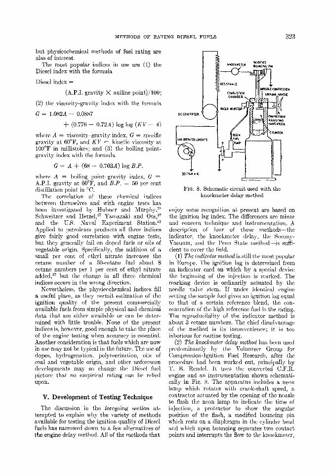
FIG. 8. Schematic circuit used with the knockmeter delay method
enjoy some recognition at present are based on the ignition lag index. The differences are minor and concern technique and instrumentation. A description of four of these methods-- the indicator, the knockmeter delay, the Socony- Vacuum, and the Penn State method--is suffi- cient to cover the field.
(1) The indicator method is still tile most popular in Europe. The ignition lag is determined from an indicator card on which by a special device the beginning of the injection is marked. The marking device is ordinarily actuated by the needle valve stem. If under identical engine setting the sample fuel gives an ignition lag equal to that of a certain reference blend, the con- centration of the high reference fuel is the rating. The reproducibility of the indicator method is about 3 eetane numbers. The chief disadvantage of the method is its inconvenience; it is too laborious for routine testing.
(2) The knockmeter delay method has been used predominantly by the Volunteer Group for Compression-Ignition Fuel Research, after the procedure had been worked out, principally by T. B. Rendel. I t uses the converted C.F.R. engine and an instrumentation shown schemati- ta l ly in Fig. 8. The apparatus includes a neon lamp which rotates with crank-shaft speed, a contractor actuated by the opening of the nozzle to flash the neon lamp to indicate the time of injection, a protractor to show the angular position of the flash, a modified bouncing pin which rests on a diaphragm in the cylinder head and which upon bouncing separates two contact points and interrupts the flow to the knockmeter,
3 2 4 METHODS OF RATING DIESEL FUELS
I ~ ) I J: r~y,~r
Neon Lo~p
Powe~ Sop~ ~ Thermal:ton L,/ai~ I !
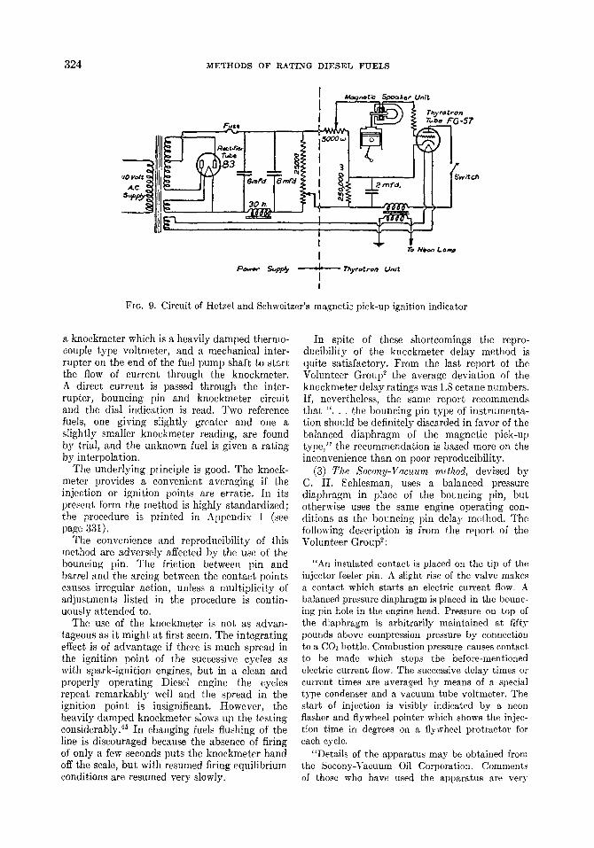
Fro. 9. Circuit of Hetzel and Schweitzer's magnetic pick-up ignition indicator
a knoekmeter which is a heavily damped thermo- couple type voltmeter, and a mechanical inter- rupter on the end of the fuel pump shaft to start the flow of current through the knockmeter. A direct current is passed through the inter- rupter, bouncing pin and knockmeter circuit and the dial indication is read. Two reference fuels, one giving slightly greater and one a slightly smaller knockmeter reading, are found by tri~l, ~nd the unknown fuel is given a r~ting by interpolation.
The underlying principle is good. The knock- meter provides a convenient averaging if the injection or ignition points are erratic. In its present form the method is highly standardized; the procedure is printed in Appendix I (see page 331).
The convenience and reproducibility of this method are adversely affected by the use of the bouncing pin. The friction between pin and barrel and the arcing between the contact points causes irregular action, unless a multiplicity of adjustments listed in the procedure is contin- uously attended to.
The use of the knockmeter is not as advan- tageous as it might at first seem. The integrating effect is of advantage if there is much spread in the ignition point of the successive cycles as with spark-ignition engines, but in a clean and properly operating Diesel engine the cycles repeat remarkably well and the spread in the ignition point is insignificant. However, the heavily damped knockmeter slows up the testing considerably. 45 In changing fuels flushing of the line is discouraged because the absence of firing of only a few seconds puts the knockmeter hand off the scale, but with resumed firing equilibrium conditions are resumed very slowly.
In spite of these shortcomings the repro- dueibility of the kncckmeter delay method is quite satisfactory. From the last report of the Volunteer Group ~ the average deviation of the knockmeter delay ratings was 1.8 cetane numbers. If, nevertheless, the same report recommends that " . . . the bouncing pin type of instrumenta- tion should be definitely discarded in favor of the balanced diaphragm of the magnetic pick-up type," the recommendation is based more on the inconvenience than on poor reproducibility.
(3) The Socony-Vacuum method, devised by C. H. ~chlesman, uses a balanced pressure diaphragm in place of the boLncing pin, but otherwise uses the same engine operating con- ditions as the bouncing pin delay method. The following description is from the report of the Volunteer Group 2:
"An insulated contact is placed on the tip of the injector feeler pin. A slight rise of the valve makes a contact which starts an electric current flow. A balanced pressure diaphragm is placed in the bounc- ing pin hole in the engine head. Pressure on top of the dlaphragm is arbitrarily maintained at fifty pounds above compression pressure by connection to a CO2 bottle. Combustion pressure causes contact to be made which stops the before-mentioned electric current flow. The successive delay times or current times are averaged by means of a special type condenser and a vacuum tube voltmeter. The sturt of injection is visibly indicated by a neon flasher and flywheel pointer which shows the injec- tion time in degrees on a flywheel protractor for each cycle.
"Details of the apparatus may be obtained from the Socony-Vacuum Oil Corporation. Comments of those who have used the apparatus are very

METHODS OF RATING DIESEL FUELS 3 2 5
favorable in regard to ease of handling and the results compare well among themselves and also with averages by the bouncing pin delay method."
While the Seeeny-Vacuum method is no doubt superior to the knockmeter delay method in convenience, in reproducibility it is a little inferior, showing an average deviation of 2.1 octane numbers from the "true" values. b (4) The Penn State method was devised by Hetzel and ~ehweitzer? ~ In this method the bouncing pin was replaced by an electromagnetic pick-up, such as is used for phonographs and radio speakers of the magnetic type. A short stiff wire resting on the diaphragm transmits the motion of the diaphragm to the armature of the pick-up. The electromotive force generated in the coil surrounding the armature is used to control the operation of a thyratron tube. When the velocity of the diaphragm is high, as at the time of ignition, the thyratron relay trips and causes a neon lamp to flash. The timing of the flash is read on the protractor.
The circuit is shown in Fig. 9. The current generated in the coil reduces the negative voltage on the grid of the thyratron tube, thereby causing it to e~nduet, and permits a condenser to discharge. The current thus passing to the plate of the tube goes to a coil, which in turn sends a flash through the neon lamp. The neon lamp flashes once in every cycle, at the moment the velocity of the pick-up motion reaches a pre- determined magnitude. At any other time the voltage generated is insufficient to trip the thyratron relay, and the neon lamp remains dark.
A pick-up identical with the one described is mounted on the end of the needle valve stem and indicates the injection. A small neon lamp of the low voltage type is connected to each pick-up and mounted on the fly-wheel, which is provided with a stationary angle scale for reading the position of the neon flashes to an accuracy of 1/10th of a degree.
The mechanism of the pick-up is practically frictionless. No electric contacts are used, and therefore troubles with arcing and pitting are eliminated. The wire and armature have a high natural frequency, so that they follow faithfully the motion impressed upon them. Both pick-ups are claimed to be insensitive to rough handling and to the manner in which they are mounted.
The technique followed in conjunction with the magnetic pick-ups is known as the "fixed ignition lag method." The injection timing is kept at, say, 18 degrees crank angle before top center. Ignition is always to occur at top center exactly. For low cetane fuel the required compression ratio to produce top center ignition (after 18 degrees ignition lag) is high; for high cetane fuels it is low.
21
19
CALIBRATION OF PRIMARY REFERENCE CELLS
INdECTION -18 DEG IGNITION 0 DEG
17
d J 15..
13~-
11-- ! I I
30 50 70 90
CETANE NUMBER
FIG. 10. Calibration curve of the required compression ratio versus eetane number
By moving the adjustable plug the compression ratio is adjusted until the neon lamp indicates ignition at top center.
If the R.C.R. (required compression ratio) of the test fuel is equal to that of the reference blend, the ignition qualities of both are equal. Absolute matching may not be easy to obtain, but the unknown fuel can always be bracketed between two reference fuels and the rating ap- proximated by interpolation.
If a number of samples are to be tested in one day, the use of a calibration curve is economical. By testing a number of the reference blends and noting the R.C.R. for each blend, a curve of R.C.R. versus eetane number is plotted on cross section paper. By determining the R.C.R. of the unknown fuel and marking it on the calibration curve, its cetane number can be read. Figure 10 is a typical calibration curve obtained under the operating conditions listed in Appendix II. For approximate rating a permanent calibration curve can be used. For accurate rating, however, a "day curve" or bracketing is necessary.
The advantages claimed for the Penn State method are the speed and accuracy with which the tests are performed and the simple reliable apparatus which is used. All of the waiting associated with the other methods is eliminated,
326 METHODS OF RATING DIESEL FUELS
/ O v
s d zeed -/fP.M
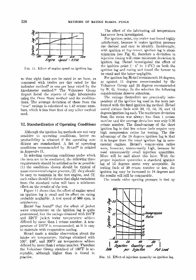
FIG. 11. Effect of engine speed on ignition lag.
so that eight fuels can be rated in an hour, as compared with twelve per day rated by the indicator method 6 or one per hour rated by the knockmeter methodY The Volunteer Group Report listed the reports of eight laboratories using the Penn State method and its modifica- tions. The average deviation of these from the "true" ratings is calculated as 1.42 eetane num- bers, which is less than that of any other method used.
VI. Standardizat ion of Operating Condit ions
Although the ignition lag methods are not very sensitive to operating conditions, better re- producibility is attained if the operating con- ditions are standardized. A list of operating conditions recommended by Hetze119 is printed in Appendix II.
In selecting operating conditions under which the tests are to be conducted, the following three requirements should be satisfied as far as possible: (1) the conditions chosen should be typical of usual commercial engine practice, (2) they should be easy to maintain in the test engine, and (3) such values should be chosen that slight variations from the standard value will have a minimum effect on the results of the test.
Figure 11 shows that the effect of engine speed on ignition lag is small and its effect on rating probably negligible. A test speed of 900 rpm. is satisfactory.
Hetzel has found 19 that the effect of jacket water temperature on the ignition lag is quite pronounced, but, the ratings obtained with 210~ and 328~ jacket water temperature seldom differed by more than 1 eetane number. A tem- perature of 210~ is recommended, as it is easy to maintain with evaporative cooling.
Hetzel made a similar observation about the intake air temperature. Ratings obtained with 100 ~ 150 ~ and 200~ air temperature seldom differed by more than 1 eetane number. Therefore the Volunteer Group standard of 150~ is ac- ceptable, although higher than is found in practice.
The effect of the lubricating oil temperature has never been investigated.
For ignition point, top center was found highly satisfactory, because it makes ignition pressure rise distinct and easy to identify. Incidentally, with ignition at top center, ignition lag is about minimum (see Fig. 6), therefore a deviation in injection timing will cause minimum deviation in ignition lag. Hetzel investigated the effect of the ignition point (--4 ~ to +2~ on both the ignition lag and rating and found the former to be small and the latter negligible.
For ignition lag Hetzel recommends 18 degrees, as against 11 degrees recommended by the Volunteer Group and 15 degrees recommended by W. G. Ainslcy. In the selection the following considerations deserve attention.
The ratings themselves are practically inde- pendent of the ignition lag used in the tests per- formed with the fixed ignition lag method. Hetzel tested sixteen fuels with 10, 12, 14, 16, and 18 degrees ignition lag each. The maximum deviation from the mean was always less than 1 cetane number and the average deviation was only 0.36 cetane mnnber. The disadvantage of the short ignition lag is that low cetane fuels require very high compression ratios for testing. The dis- advantage of the 18 degrees ignition lag is that it is longer than the usual ignition lag in com- mercial engines. Hetzel's compression ratios were, however, unnecessarily high, because he used unnecessarily small injection quantities. More will be said about this later. With the proper injection quantities a standard ignition lag of 15 degrees seems very acceptable. In testing fuels of 30 cetane number or less, the ignition lag may be increased to 18 degrees and the results will still be comparable.
The nozzle valve opening pressure is tied up
\ ~s '~
, -. .,.
h- ~pr~/on l?ot/a "
$
2~../~,,'ion Ouontitr m~." "l Idle per lzjed]on fall Load
FIG. 12. Effect of injection quantity on ignition lag.
METHODS OF RATING DIESEL FUELS 327
with the nozzle and the injection line. I t may be anything between 1200 and 2500 psi, provided the injection is regular. Double injections make testing difficult. Hetzel obtained regular in- jections with 1300 4- 100 psi with a Bosch nozzle DM30S3 and a A-in.- )< 25-in.-tube. For a given nozzle and tube the proper opening pressure can be determined by indicating the needle lift with a pick-up and oscillograph. In the range mentioned the ignition lag is independent of the opening pressure.
Fuel quantity injected per cycle has a greater effect on ignition lag than was suspected. Figure 12 shows the relation for a 55 cetane number fuel. Hetzel chose a fuel quantity as small as 20 mm 3, "because this is sufficient to give regular injec- tions, but is not so much as to produce violent combustion when poor fuels are burned." How- ever, at low compression ratios the ignition lag is very sensitive to the injected fuel quantity, especially if the latter is small. This by itself is a disadvantage. The tentative standard of the Volunteer Group is 13 cng/min or 29 mm a per injection. Figure 12 shows that injection quantity should be increased at least to that amount which would bring it closer to the flat nonsen- sitive region. I t also has the further advantage that it would reduce the required compression
ratio and make the ignition lag standard of 15 degrees more attractive. Of course an increased injection quantity requires more frequent cleaning of the engine.
The potentiometer settings should be such as to give earliest indications of injection and ignition, respectively. In exceptional cases it is possible to obtain "combustion flash" on com- pression alone, therefore as a precaution the ignition potentiometer setting should be checked so that with injection cut off no flash occurs. With ignition at top center the combustion pressure rise is so rapid that the ignition lag read is almost independent of the potentiometer setting and no precise adjustment is necessary.
VII. Present Status of Diesel Fuel Testing, Technically and Commercially
In this country the working out of a method for testing Diesel fuels on ignition quality is in the hands of the Volunteer Group for Com- pression-Ignition Fuel Research, in which all major oil companies are represented. Under the chairmanship of T. B. Rendel this organization has worked hard for two years to solve the problem, and it is near to its goal now. It is
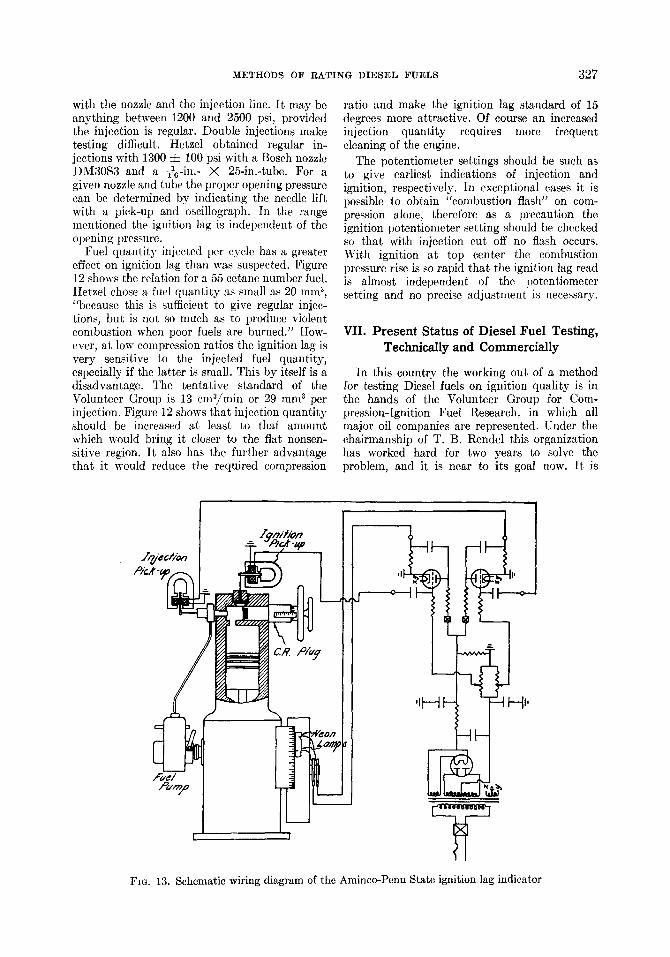
f u e l P ~ p
I
,IH H,,
[~;~176176176176
FIG. 13. Schematic wiring diagram of the Aminco-Penn State ignition lag indicator

~ 2 8 METHODS OF RATING DIESEL FUELS
FIG. 14. Aminco-Penn State ignition lag indicator mounted on a C.F.R. Diesel fuel-testing en~ne.
predicted that within a short time this group will be prepared to submit to the A.S.T.M. a tentative standard for adoption.
There is universal agreement that Diesel fuels be rated for ignition quality in an engine on the basis of their ignition delay and that the rating be expressed in terms of cetane numbers. There is almost universal agreement that the high turbulent Diesel conversion to the C.F.R. engine shall be used for testing. Although the nonturbulent type of engine has an advantage for fuel testing in being more sensitive to ignition quality, this is overweighed by the fact that the popular high-speed Diesel engines in this country are of the turbulent type.
The only item still left open is the exact type of instrumentation, but even therein considerable progress has been made lately. The bouncing pin has been definitely discarded in favor of the balanced diaphragm of magnetic pick-up type of instrumentation. The latter type has been simplified and made more convenient by the American Instrument Company. The American instrument employs the simplified wiring shown in Fig. 13, designed by R. L. Alcorn, Jr., and J. S. Chandler, and an improved protractor in which the injection neon lamp and ignition neon lamp are displaced by 15 degrees (an 18 degree offset can also be used). If the compression ratio
is properly adjusted for the fuel, the two neon flashes appear as a single luminous line.
Figure 14 shows the pick-ups mounted on the C.F.R. engine, while Fig. 15 shows the encased electronic relay, weighing 7.5 lb.
In Europe the Diesel fuel testing is largely in the hands of the Institute of Petroleum Tech- nologists. The Institute agrees with the American Volunteer Group in the principle of engine method based on ignition delay, but leaves open to the tester the choice of engine and the instrumenta- tion. According to the I.P.T. plan the ratings are reported in ignition numbers, obtained by ex- pressing the percentage of the high ignition quality reference fuel in the low ignition quality reference fuel, divided by ten and reporting to the nearest half number. The I.P.T. discourages the use of primary reference fuels (cetene), and favors the use of secondary reference fuels on account of the more consistent results obtained thereby on a variety of types of engines. The Volunteer Group, however, does not consider it practical to adopt secondary reference fuels over a long period of time and favors the use of primary reference fuels such as octane and alpha-methylnaphthalene.
It is notable that while Diesel fuel testing is more advanced in this country than abroad, in the use of Diesel fuels we are far behind. This

METHODS OF RATING DIESEL FUELS 329
FIG. 15. Electronic relay of the Aminco-Penn State ignition lag indicator
refers to automotive application, especially to trucks and busses.
In England, France, and Germany the majority of large trucks and busses produced in the last couple of years are equipped with Diesel engines, while in this country only a fraction of 1 per cent is so equipped. The chief incentive for the use of the Diesel engine abroad is its economy: the fuel mileage is roughly double, and, furthermore, there is considerable difference in the price of Diesel fuel and gasoline. In this country gasoline is cheap and the introduction of the Diesel engine correspondingly'slow. The one exception is the tractor field, where one prominent builder is turning out Diesel tractors at the rate of about a thousand a month.
The present consumption of Diesel fuel in the U.S. is roughly estimated at 30 million barrels per year and is rapidly rising. Under these circum- stances the commercial significance of Diesel fuel testing is expected to grow, even if it may not quite reach the commercial significance of the octane rating. The possible introduction of successful Diesel fuel dopes will greatly increase the demands on ignition quality rating.
REFERENCES
1. American Society for Testing Materials: Min- utes of the Meeting of the Coordinating Sub- committee on Diesel Fuel (a subcommittee of Technical Committee C of D-2) at White Sulphur Springs, June 19, 1935.
2. BAXTER, C. H. AND RENDEL, W. B.: Report of the Volunteer Group for Compression-Ignition Fuel Research; paper presented at the Meeting of the Society of Automotive Engineers, May 4-9, 1937.
3. BE&LE, E. S. L. AND STANSFIELD, R.: The
Sunbury Knock Indicator; paper presented at the Meeting of the Society of Automotive Engineers, May, 1937.
4. BECKER AND FISCHER: SAE Journal 35, 376 (1934).
5. BECKER, A. E. AND STACEY, H. R.: Measure- ment of Ignition Qualities of Diesel Fuels; Paper No. 211, World Petroleum Congress, London, 1933.
6. BOERLAGE, G. D. AND BROEZE, J. J.: Engi- neering 132, 603, 687, 755 (1931).
7. BOERLAGE, G. D. AND BROEZE, J. J.: SAE Journal 81, 283 (1932).
8. BOERLAGE, G. D. AND BROEZE, J. J . : Knock Rating for High-speed Compression Ignition Engine Fuels; Paper No. 111, World Petroleum Congress, London, 1933.
9. BOERLAGE, G. D. AND BROEZE, J. J . : Chem. Rev. 22, 61 (1938); Second Symposium on Combustion (Reprint), p. 285, this volume.
10. BRIDGEMAN, O. C. AND MARVIN, C. F., JR.: Ind. Eng. Chem. 20, 1219 (1928).
11. BUTLER, W. H.: Fuels for Automotive Diesels; paper presented at the Meeting of the Society of Automotive Engineers, June, 1931.
12. CARPENTER, n . E. i . AND STANSFIELD, m.: Combustion in Heavy Oil Engines; paper presented at the Meeting of the North East Coast Institute of Engineers and Shipbuilders, February 26, 1932.
13. CONSTAM AND SCItLAEPFER: Z. Ver. deut. Ing. 57, 1489 (1913).
14. DUMANOIS, P.: Compt. rend. 196 (April 3, 1933). 15. FOORD, F. A.: J. Inst. Petroleum Tech. 18, 533
(1932). 16. HAWKES, C. J.: Engineering 110, 749 (1920). 17. HEINZE, R.: Braunkohle 35, 639 (1935). 18. HESSELMAN: Z. Ver. deut. Ing. 67, 650 (1923).
330 METHODS OF RATING DIESEL FUELS
19. HETZEL, T. B.: The Development of Diesel Fuel Testing; Penn. State Coll. E. E. S. Bull. No. 45 (1936).
20. HETZEL, W. B. AND SCHWEITZER, P. H.: Auto- motive Ind. 73, 202 (1935).
21. HILL, J. B. AND COATES, H. B.: Ind. Eng. Chem. 20, 641 (1928).
22. HOLFELI)ER: Forschungsheft No. 374, Beilage zu Forsch. Gebiete Ingenieurw. 6, Sept.-Oct. 1935; t ranslat ion in Natl. Advisor)- Com. Aeronaut. Teeh. Mere. 790.
23. HOLM, H.: Z. angew. Chem. 26, 273 (1913). 24. HUBNER, W. H.: SAE Journal 40, 40 (1937). 25. HUBNER, W. H. AND MURPHY, G. B.: Natl.
Petroleum News 28, No. 4, 22, 24, 28; No. 5, 25 (1935).
:~5a. Ins t i tu te of Petroleum Technologists: Ignition Quality of Diesel Fuels, issued November, 1936.
26. JACKSON, E. A.: Oil Gas J. 33, No. 44, 16 (1935). 27. JOACHIM: Diesel Power 13, No. 5, May, 1935. 28. KREULEN, D. J. W.: J. Inst. Petroleum Tech.
23, No. 162, 253 (1937). 29. LEMEsuRIER, L. J. AND STANSF1ELD, R.: J. Inst.
Petroleum Teeh. ]7, 387 (1931). 30. MACGREGOR, J. R.: Discussion presented at the
Summer Meeting of the Society of Automotive Engineers, June, 1934.
31. GOOD, R. F.: SAE Journal 40, No. 6, 232 (1937). 32. MARDER, M. AND SCHNEIDER, P.: Automobil-
tech. Z. 40, (April 25, 1937). 33. MmHAILOVaX: Compt. rend. acad. sci. U.R.S.S.
[N.S.] 2, No. 4, 96 (1936); t ranslat ion in Natl. Advisory Com. Aeronaut. Tech. Mere. 813.
34. MOORE, C. C. JR.: SAE Journal 40, 251 (June, 1937) (discussion).
35. MOORE, C. C., JR., AND KAYE, G. R.: Oil Gas J. 83, No. 26, 108 (1934).
36. MOORE, H.: J. Inst. Petroleum Tech. 6, 186 (1919-20).
37. Navy Department, Bm'eau of Engineering: Report E on Diesel Fuel Investigation, 1937 (available in mimeographed form).
38. Natl. Advisory Coln. Aeronaut. Tech. Note 418. 39. NEUMANN: Z. Ver. deut. Ing. 70, 1076 (1926). 40. POPE, A. W., JR. AND MURDOCK, J. A.: SAE
Journal 30, 136 (1932). 41. I~ENDEL, W. B.: Proceedings of the Eighth Oil
Power Conference; Penn. State Coll. Tech. Bull. No. 20, p. 93, (1934).
42. RENDEL, T. B.: SAE Journal 38, No. 6, 225 (1936); Report of Volunteer Group for Com- pression-Ignition Fuel Research.
43. RIEPPEL: Z. Ver. deut. Ing. 51, 613 (1907). 44. ROSE, R. A., WILSON, G. C., AND BENEDICT,
R. R.: SAE Journal 39, 459 (November, 1936). 45. SCHWEITZER, P. H.: Proceedings of the Sixth
Oil Power Conference; Penn. State Coll. Tech. Bull. No. 16, p. 73, 1932.
46. SCHWEITZER, P. H., DICKINSON, H. A., AND REED, M. J. : Status of Diesel Fuel Oil Standard- ization in the United States; Paper No. 78, World Petroleum Congress, London, 1933.
47. SCHWEITZER, P. H., AND HETZEL, W. B.: SAE Journal 38, No. 5, 206 (1936).
48. STANSFIELD, R.: The Ignition Quali ty of Fuels, etc.; Paper No. 77, World Petroleum Congress, London, 1933.
49. SUGDEN, S.: J. Chem. Soc. 125, 1177 (1924). 50. TAusz AND SCHULTE: Z. Ver. deut. Ing. 78, 577
(1934). 51. WOLLERS AND EHMCKE: Krupp Monatsh. 2,
1 (1921). 52. YAMAZAKI, K. AND OTA, S.: J. Fuel Soc. Japan
14, 134 (1935).
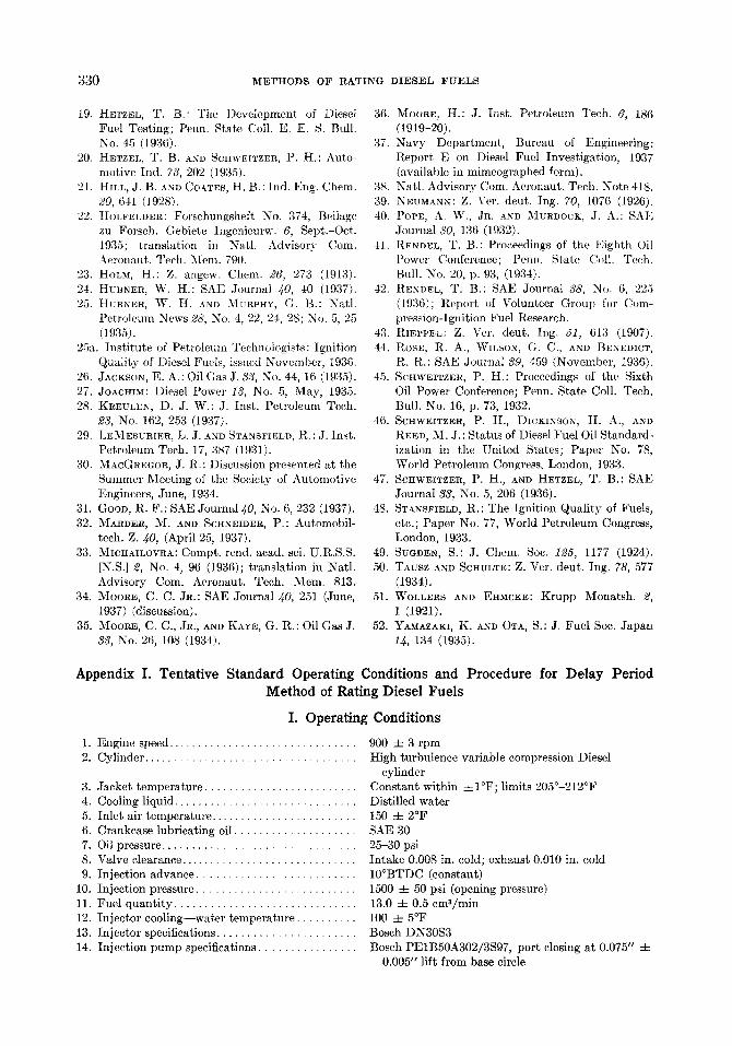
Appendix I. Tentative Standard Operating Conditions and Procedure for Delay Period Method of Rating Diesel Fuels
I. Operating Conditions
1. Engine speed . . . . . . . . . . . . . . . . . . . . . . . . . . . . . . . 900 • 3 rpm 2. Cylinder . . . . . . . . . . . . . . . . . . . . . . . . . . . . . . . . . . . High turbulence variable compression Diesel
cylinder 3. Jacket temperature . . . . . . . . . . . . . . . . . . . . . . . . . Constant within • 1 7 6 limits 205~176 4. Cooling liquid . . . . . . . . . . . . . . . . . . . . . . . . . . . . . . Distilled water 5. Inlet air temperature . . . . . . . . . . . . . . . . . . . . . . . . 150 • 2~ 6. Crankcase lubricating oil . . . . . . . . . . . . . . . . . . . . SAE 30 7. Oil pressure . . . . . . . . . . . . . . . . . . . . . . . . . . . . . . . . 25-30 psi 8. Valve clearance . . . . . . . . . . . . . . . . . . . . . . . . . . . . . In take 0.008 in. cold; exhaust 0.010 in. cold 9. Inject ion advance . . . . . . . . . . . . . . . . . . . . . . . . . . 10~ (constant)
10. Injection pressure . . . . . . . . . . . . . . . . . . . . . . . . . . 1500 • 50 psi (opening pressure) 11. Fuel quan t i ty . . . . . . . . . . . . . . . . . . . . . . . . . . . . . . 13.0 :t: 0.5 cm3/min 12. Injector cooling--water temperature . . . . . . . . . . 100 • 5~ 13. Injector specifications . . . . . . . . . . . . . . . . . . . . . . . Bosch DN30S3 14. Inieet ion pump specifications . . . . . . . . . . . . . . . . Bosch PE1B50A302/3S97, port closing at 0.075" •
0.005" lift from base circle
M E T H O D S OF R A T I N G D I E S E L F U E L S 331
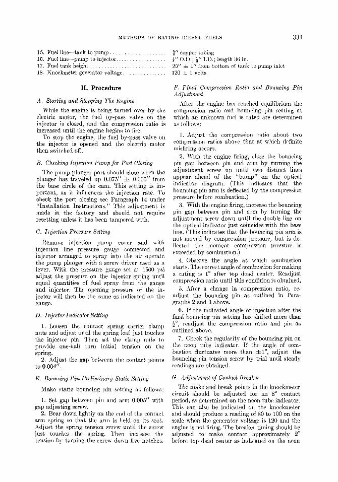
15. Fuel line--tank to pump . . . . . . . . . . . . . . . . . . . . ~-" copper tubing 16. Fuel line--pump to injector. . . . . . . . . . . . . . . . . . l,, O.D.; ~" I.D.; length 36 in. 17. Fuel tank height . . . . . . . . . . . . . . . . . . . . . . . . . . . 25" 4- 1" from bottom of tank to pump inlet 18. Knoekmeter generator voltage . . . . . . . . . . . . . . . 120 =t= 1 volts
II. Procedure
A. Starting and Stopping The Engine
While the engine is being turned over by the electric motor, the fuel by-pass valve on the injector is closed, and the compression ratio is increased until the engine begins to fire.
To stop the engine, the fuel by-pass valve on the injector is opened and the electric motor then switched off.
B. Checking Injection Pump for Port Closing
The pump plunger port should close when the plunger has traveled up 0.075" :l: 0.005" from the base circle of the cam. This setting is im- portant, as it influences the injection rate. To check the port closing see Paragraph 14 under "Installation Instructions." This adjustment is made in the factory and should not require resetting unless it has been tampered with.
C. Injection Pressure Setting
Remove injection lmmp cover and with injection line pressure gauge connected and injector arranged to spray into the air operate the pump plunger with a screw driver used as a lever. With the pressure gauge set at 1500 psi adjust the pressure on the injector spring until equal quantities of fuel spray from the gauge and injector. The opening pressure of the in- jector will then be the same as indicated on the gauge.
D. Injector Indicator Setting
1. Loosen the contact spring carrier clamp nuts and adjust until the spring leaf just touches the injector pin. Then set the clamp nuts to provide one-half turn initial tension on the spring.
2. Adjust the gap between the contact points to 0.004".
E. Bouncing Pin Preliminary Static Setting
Make static bouncing pin setting as follows:
1. Set gap between pin and arm 0.005" with gap adjusting screw.
2. Bear down lightly on the end of the contact arm spring so that the arm is held on its seat. Adjust the spring tension screw until the screw just touches the spring. Then increase the tension by turning the screw down five notches.
F. Final Compression Ratio and Bouncing Pin Adjustment
After the engine has reached equilibrium the compression ratio and bouncing pin setting at which an unknown fuel is rated are determined as follows:
1. Adjust the compression ratio about two compression ratios above that at which definite misfiring occurs.
2. With the engine firing, close the bouncing pin gap between pin and arm by turning the adjustment screw up until two distinct lines appear ahead of the "bump" on the optical indicator diagram. (This indicates that the bouncing pin arm is deflected by the compression pressure before combustion.)
3. With the engine firing, increase the bouncing pin gap between pin and arm by turning the adjustment screw down until the double line on the optical indicator just coincides with the base line. (This indicates that the bouncing pin arm is not moved by compression pressure, but is de- fleeted the moment compression pressure is exceeded by combustion.)
4. Observe the angle at which combustion starts. The correct angle of eombustion for making a rating is 1 ~ after top dead center. Readjust compression ratio until this condition is obtained.
5. After a change in compression ratio, re- adjust the bouncing pin as outlined in Para- graphs 2 and 3 above.
6. If the indicated angle of injection after the final bouncing pin setting has shifted more than 1o readjust the compression ratio and pin as 5 ,
outlined above. 7. Cheek the regularity of the bouncing pin on
the neon tube indicator. If the angle of com- bustion fluctuates more than =~1 ~ adjust the bouncing pin tension screw by trial until steady readings are obtained.
G. Adjustment of Contact Breaker
The make and break points in the knockmeter circuit should be adjusted for an 8 ~ contact period, as determined on the neon tube indicator. This can also be indicated on the knockmeter and should produce a reading of 80 to 100 on the scale when the generator voltage is 120 and the engine is not firing. The breaker timing should be adjusted to make contact approximately 2 ~ before top dead center as indicated on the neon
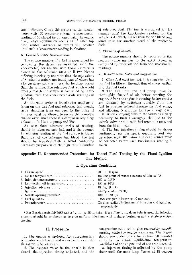
332 METHODS OF RATING DIESEL :FUELS
tube indicator. Check this setting on the knock- meter with 120 generator voltage. A knoekmeter reading of 50 should be obtained with the engine firing when combustion occurs at 1 ~ after top dead center. Advance or retard the breaker until such a knockmeter reading is obtained.
H. Cetane Number Determination
The eetane number of a fuel is ascertained by comparing the delay (as measured with the knoekmeter) for the fuel with those for various blends of the reference fuels until two blends differing in delay by not more than the equivalent of 8 eetane numbers are found, one of which has a longer delay and the other a shorter delay period than the sample. The reference fuel which would exactly nmteh the sample is computed by inter- polation from the knoekmeter scale readings of the fuels.
An alternate series of knockmeter readings is taken on the test fuel and reference fuel blends. After changing from one fuel to the other, 5 minutes must be allowed to insure the complete change over, since there is a comparatively large volume of fuel in the pump and line.
At least three alternate series of readings should be taken on each fuel, and if the average knockmeter reading of the fuel sample is higher than that of the reference fuel blend, the test should be repeated with a blend containing decreased proportion of the high eetane number
of reference fuel. The test is continued in this manner until the knockmeter reading for the sample is definitely higher than for one blend and lower than for another blend of the reference fuels.
I. Precision of Results
The cetane number should be reported in the nearest whole number to the exact rating as computed by interpolation from the knockmeter readings.
J. Miscellaneous Notes and Suggestions
1. Clean fuel must be used. It is suggested that the fuel be filtered through thin chamois leather into the fuel tanks.
2. The fuel lines and fuel pump must be thoroughly flushed of air before starting the engine. After the engine is running better results are obtained by switching quickly from one fuel to another without flushing the fuel pump, and allowing 5 minutes for the change over.
3. When changing fuels in the tanks, it is very necessary to flush thoroughly the line to the switch valve until a solid fuel stream is obtained from the bleed drain.
4. The fuel injection tinting should be shown continually on the spark quadrant and any deviation fl'om 10 ~ before top dead center must be corrected before each knoekmeter reading is taken.
Appendix II. Recommended Procedure for Diesel Fuel Testing by the Fixed Ignition Lag Method
I. Operating Conditions
1. Engine speed . . . . . . . . . . . . . . . . . . . . . . . . . . . . . . . . 900 4- 30 rpm 2. Jacket temperature . . . . . . . . . . . . . . . . . . . . . . . . . . Boiling point of water constant within 4-I~ 3. Inlet air temperature . . . . . . . . . . . . . . . . . . . . . . . . . 150 4- 0.5~ 4. Lubrication oil temperature . . . . . . . . . . . . . . . . . . . 150 4- 10~ 5. Injection advance . . . . . . . . . . . . . . . . . . . . . . . . . . . 18 deg. B.T.C. 6. Ignition . . . . . . . . . . . . . . . . . . . . . . . . . . . . . . . . . . . . At top center exactly 7. Nozzle opening pressure* . . . . . . . . . . . . . . . . . . . . . 1300 4- 100 psi 8. Fuel quantity . . . . . . . . . . . . . . . . . . . . . . . . . . . . . . . 0.020 cm 3 per injector 4- 10 per cent 9. Potentiometer . . . . . . . . . . . . . . . . . . . . . . . . . . . . . . . To give earliest indication of injection and ignition,
respectively
* For Bosch nozzle DN30S3 and a ~6-in.- • 25 in.-tube. If a different nozzle or tube is used the injection pressure should be so chosen as to give uniform injections with a sharp beginning and a single principal opening.
II. Procedure
1. The engine is motored for approximately 5 minutes while the air and water heaters and the thyratron tube warm up.
2. The by-pass valve in the nozzle is then closed, the injection timing adjusted, and the
compression ratio set to give reasonably smooth running while the engine warms up. The engine should run under power for at least 20 minutes in order to attain equilibrium temperature conditions of the engine and of the crankcase oil.
3. Injection timing is adjusted by the pump timer until the neon lamp flashes at 18 degrees

METHODS OF RATING DIESEL FUELS 333
before top center. The ignition indicator is then switched on, and the compression ratio is varied until the neon flash indicates ignition at top center. The scale reading of the compression ratio adjusting plug is then recorded. Following that, the compression ratio is increased until ignition takes place several degrees before top center, and again decreased until ignition is indicated at top center and the scale reading of the compression ratio adjusting plug is again recorded. This is repeated so that altogether two determinations are made with increasing and two with decreasing compression ratios. The average of the four readings is then used to determine the required compression ratio for that fuel. The R.C.R. is calculated by the formula R.C.R. -- 1 ~ 18/H, where H is the average of the four micrometer readings of the adjustable plug.
4. When switching from one fuel to another, the pump suction space is flushed for approxi- mately 5 sec, then, while the injection tube and
nozzle are being purged of the fuel previously used, the other tank is drained, flushed, and filled with the next fuel to be tested.
5. After testing a series of blends of the two reference fuels, the volumetric percentage of the high cetane fuel in the low octane fuel is plotted against the corresponding R.C.R. values. The tl.C.R, of the sample fuel is placed on the curve which determines the rating of the sample fuel. If the sample fuels are tested first, the R.C.R. of some of the reference blends which are outside of the range of the sample fuels need not be determined, if the approximate ratings of the fuels are known in advance, the preferred pro- eedure is to test the fuels, including the reference fuels, in the order of their ignition quality. This combines the good features of bracketing, with curvilinear interpolation, and also directly corn- pares fuels of sinfilar or identical ignition quality so that relative merit may be more surely ascer- rained.
Discussion
T. B. RENDEL (Shell Petroleum Corporation, Wood River, Illinois): Three years ago a small group, known as the Volunteer Group for Compression- Ignition Fuel Research, was formed to study and eventually to standardize a method for rating the ignition quality of Diesel fuels. This group has pursued its work actively and has submitted three reports. The most recent of these reports was presented to the Society of Automotive Engineers and the American Society for Testing Materials, giving the results of the past eighteen months' work. In this report it is concluded that results of the past eighteen months' work indicate fairly definitely that a direct matching method on the basis of ignition delay is the best from the point of view of reproducibility and validity, and that therefore some sacrifice in simplicity and speed of testing must be made. In this connection it is to be remembered that the octane number test, after several years of development and with a far greater commercial incentive behind it, sometimes requires about 45 min for determination and is still liable to errors of 1 or 2 octane numbers.
Progress in methods of instrumentation has advanced considerably. It is recommended that the
bouncing pin type of instrumentation should be definitely discarded in favor of the balanced dia- phragm or the magnetic pick-up type. Further work in a larger number of laboratories is desirable before definitely standardizing on this point. The cetane number is, however, not apparently affected outside the limit of error of the determination.
It is therefore recommended that Diesel fuel be rated for ignition quality on the basis of its cetane number, as determined by an ignition delay method on the high turbulent Diesel conversion of the C.F.R. engine, the exact type of instrumentation for recording the delay to be left to the option of the user pending further work of the Volunteer Group.
The Volunteer Group has investigated Professor Schweitzer's mechanical pick-up type of instrument and is favorably impressed with its operation; cooperative work is now in hand with this instru- ment. Work is also planned on the correlation with actual service engines. In this connection, it is very encouraging to note that cetane rating is apparently insensitive to the type of engine and operating conditions, which in turn indicates that correlation with service engines is not far off.