Embed Size (px)
Citation preview

www.gimatic.com28
03
/20
15
MGX
MGX2508
MGX4015
MGX6030
MGX2005 MGX3210 MGX5020
MGX3214
NEW
MGX
PNEU
MAT
IC G
RIPP
ERS
2-jaw parallel grippers
MGX2005 MGX2508 MGX3210 MGX3214 MGX4015 MGX5020 MGX6030
Medium Filtered, lubricated / non lubricated compressed air
Operating pressure range 1 ÷ 8 bar
Operating temperature range 5° ÷ 50°C.
Gripping force at 6 bar on each jaw 90 N 145 N 230 N 160 N 375 N 650 N 830 N
Total gripping force at 6 bar 180 N 290 N 460 N 320 N 750 N 1300 N 1660 N
(±0.3 mm)Total stroke 5 mm 8 mm 10 mm 14.6 mm 15 mm 20 mm 30 mm
Maximum working frequency 3 Hz 3 Hz 3 Hz 3 Hz 2 Hz 2 Hz 2 Hz
Cycle air consumption 5 cm3 10 cm3 22 cm3 22 cm3 48 cm3 86 cm3 169 cm3
Opening / Closing time without load 7 ms 10 ms 20 ms 20 ms 50 ms 70 ms 140 ms
Repetition accuracy 0.02 mm 0.02 mm 0.02 mm 0.02 mm 0.02 mm 0.02 mm 0.02 mm
Weight 95 g 150 g 270 g 270 g 545 g 900 g 1525 g
Pinze parallele
2-jaw parallel self-centering pneumatic gripperseries MGX• Flat profile.• Robust guide.• High gripping force.• Small weight and dimensions.• High dimensional accuracy.• Spring closed (-NC) or spring open (-NO) option.• Food grade grease FDA-H1.
Parallel grippers

www.gimatic.com 29
03
/20
15
MGX
MGX2005 MGX2508 MGX3210 MGX3214 MGX4015 MGX5020 MGX6030A 35.8 42 51 51 61.2 70 78.6B 44 55 62 62 93 118 153C ±0.04 28.3 33 42 42 51 58 66D1 Ø5 H7 Ø7 H7 Ø7 H7 Ø7 H7 Ø7 H7 Ø9 H7 Ø9 H7D2 Ø3.2 Ø4.2 Ø4.2 Ø4.2 Ø5.2 Ø6.2 Ø6.2D3 Ø5 H7 Ø7 H7 Ø7 H7 Ø7 H7 Ø9 H7 Ø12 H7 Ø9 H7D4 M3 M4 M5 M5 M6 M8 M6D5 M5 M5 M5 M5 M5 G1/8” G1/8”D6 M3 M3 M3 M3 M3 M3 M3E ±0.02 36.5 46 52 52 80 105 140F 12.5 15.5 18 18 27.5 37 43.5G 27.2 33.6 41.4 41.4 49.6 58.6 67.6H ±0.05 14 16 22 22 25 28 30I 26 28.5 36 36 42 49 58J 22 24 31 31 37 43 51K 4 4.5 5 5 5 6 7L 11.2 12.7 16 16 20 25 29M 49 63 72 76 108 138 183N 44 55 62 62 93 118 153P1 1.2 1.5 1.5 1.5 1.5 2 2P2 5.5 6 8.4 8.4 9 10 13.5P3 1.2 1.5 1.5 1.5 2 2.5 2.5P4 5 5.2 7 7 9 12 12Q 11 12 16 16 31.2 32 40R ±0.02 9 10 12 12 12 24 20S 5.5 6 8 8 12.5 14 15T 5.8 6 6 6 6 8 8U 20.8 24 33 33 41.2 46 54.6V 29 37 42 42 65 88 106Z 17 20 26 26 30 33 35PZ 0.5 0.5 0.8 0.8 0.8 0.8 0.8
MGX6030
PNEU
MAT
IC G
RIPP
ERS
2-jaw parallel grippers
Dimensions (mm) D1
D5
D6
D7
D9
Through hole for gripper fastening
Air connection
Direct air feeding
Inductive sensor mounting hole
Magnetic sensor slot
D8
With inductive sensors
OPEN
CLOSE

www.gimatic.com30
03
/20
15
MGX
150
125
100
75
50
25
24120 604836
0
360
300
240
180
120
60
0
600
500
400
300
200
100
0
1200
1000
800
600
400
200
0
1200
1000
800
600
400
200
0
240
200
160
120
80
40
0
4 bar
6 bar
8 bar
4 bar
6 bar
8 bar
4 bar
6 bar
8 bar
4 bar
6 bar
8 bar
4 bar
6 bar
8 bar
4 bar
6 bar
8 bar
MGX2005 MGX2008
MGX3210 MGX4015
MGX5020 MGX6030
Z (mm)
240
200
160
120
80
40
40200 1008060
0
4 bar
6 bar
8 bar
MGX3214
Z (mm)
40200 1008060Z (mm)
48240 1209672Z (mm)
60300 15012090Z (mm)
76380 190152114Z (mm)
32160 806448Z (mm)
PNEU
MAT
IC G
RIPP
ERS
2-jaw parallel grippers
Gripping forceThe graphs show the gripping force on each jaw, as a function of the operating pressure and the gripping tool length Z.
Grip
ping
forc
e (N
)G
rippi
ng fo
rce
(N)
Grip
ping
forc
e (N
)
Grip
ping
forc
e (N
)
Grip
ping
forc
e (N
)
Grip
ping
forc
e (N
)
Grip
ping
forc
e (N
)
The force shown in these graphs refers to one jaw. The total force is double.

www.gimatic.com 31
03
/20
15
MGX
60
90N
230N
186N
155N
135N
119N
105N
650N
560N
490N
435N
390N
350N
375N
325N
277N
239N
209N
186N
830N
725N
640N
570N
510N
460N
145N
127N
112N
99N
87N
76N
80N
71N
63N
55N
48N48
36
24
12
120 24 36 48 60 160 32 48 64 80
200 40 60 80 100 240 48 72 96 120
300 60 90 120 150 380 76 114 152 190
0
80
64
48
32
16
0
100
80
60
40
20
0
120
96
72
48
24
0
150
120
90
60
30
0
190
152
114
76
38
0
Z (m
m)
Z (m
m)
Z (m
m)
Z (m
m)
Z (m
m)
Z (m
m)
X (mm)
100
160N
132N
114N
104N
99N
96N80
60
40
20
200 40 60 80 100
0
Z (m
m)
X (mm)
X (mm)
X (mm) X (mm)
X (mm) X (mm)
MGX3214
MGX2005
MGX3210
MGX5020
MGX2508
MGX4015
MGX6030
PNEU
MAT
IC G
RIPP
ERS
2-jaw parallel grippers
Gripping forceThe graphs show the gripping force on each jaw, as a function of the gripping tool length Z and the overhanging X at 6 bar.Decrease the air pressure to 5bar, if the gripper is used in the red area.

www.gimatic.com32
03
/20
15
MGX
MGX2005 MGX2508 MGX3210 MGX3214 MGX4015 MGX5020 MGX6030
F s 300 N 400 N 650 N 500 N 1000 N 1500 N 2000 N
Mx s 4 Nm 8 Nm 15 Nm 12 Nm 30 Nm 65 Nm 110 Nm
My s 12 Nm 24 Nm 55 Nm 40 Nm 70 Nm 95 Nm 155 Nm
Mz s 3 Nm 6 Nm 12 Nm 10 Nm 24 Nm 48 Nm 90 Nm
F d 2 N 3 N 6 N 5 N 10 N 17 N 25 N
Mx d 6 Ncm 13 Ncm 34 Ncm 25 Ncm 47 Ncm 80 Ncm 155 Ncm
My d 6 Ncm 13 Ncm 34 Ncm 25 Ncm 47 Ncm 80 Ncm 155 Ncm
Mz d 6 Ncm 13 Ncm 34 Ncm 25 Ncm 47 Ncm 80 Ncm 155 Ncm
m 100 g 200 g 400 g 400 g 600 g 1000 g 1500 g
PNEU
MAT
IC G
RIPP
ERS
2-jaw parallel grippers
Safety loadsCheck the table for maximum permitted loads.Excessive forces or torques can damage the gripper, cause functioning troubles and endanger the safety of the operator.F s, Mx s, My s, Mz s, are maximum permitted static loads. Static means still jaws.F d, Mx d, My d, Mz d, are maximum permitted dynamic loads. Dynamic means running jaws.m, is the maximum permitted weight of each gripping tool, when the gripper works without speed adjustment.If the weight is over the permitted value, it is necessary to decrease the speed of the jaw by using flow controllers(not supplied).
GrippingThe gripper is double-acting for either internal or external gripping applications.

www.gimatic.com 33
03
/20
15
MGX
MGX2005 MGX2508 MGX3210 MGX3214 MGX4015 MGX5020 MGX6030
D1 Ø5 H7 mm Ø7 H7 mm Ø7 H7 mm Ø7 H7 mm Ø7 H7 mm Ø9 H7 mm Ø9 H7 mm
D2 Ø3.2 mm Ø4.2 mm Ø4.2 mm Ø4.2 mm Ø5.2 mm Ø6.2 mm Ø6.2 mm
SC M3 M4 M4 M4 M5 M6 M6
PC 1.2 mm 1.5 mm 1.5 mm 1.5 mm 1.5 mm 2 mm 2 mm
P2 5.5 mm 6 mm 8.4 mm 8.4 mm 9 mm 10 mm 13.5 mm
NC M3 CH5.5 M4 CH7 M4 CH7 M4 CH7 M5 CH8 M6 CH10 M6 CH10
RC Ø6 mm Ø8 mm Ø8 mm Ø8 mm Ø9 mm Ø11 mm Ø11 mm
MGX2005 MGX2508 MGX3210 MGX3214 MGX4015 MGX5020 MGX6030
D3 Ø5 H7 mm Ø7 H7 mm Ø7 H7 mm Ø7 H7 mm Ø9 H7 mm Ø12 H7 mm Ø9 H7 mm
SD M3 M4 M5 M5 M6 M8 M6
P5 6.2 mm 6.7 mm 8.5 mm 8.5 mm 11 mm 14.5 mm 14.5 mm
PD 1.2 mm 1.5 mm 1.5 mm 1.5 mm 2 mm 2.5 mm 1.5 mm
PNEU
MAT
IC G
RIPP
ERS
2-jaw parallel grippers
Gripping tool fasteningThe gripping tools must be as short and light as possible.They must be fastened by 2 screws (SD) and 2 centering sleeves (BD).
Gripper fasteningThe gripper can be fastened to a static or moving part. When on a moving part, you must pay attention to the forces created by inertia on the gripper and its load.It can be fastened from the top or from the bottom.Use 4 screws (SC) and 2 centering sleeves (BC).4 centering rings for the gripping tools and 2 centering sleeves for the housing are supplied in the packaging.

www.gimatic.com34
03
/20
15
MGX
SY
OUT
OUT
PNP
Magneto-resistive
NPN
13/7/2009
IFRM 04P15A1/LInductive proximity switch
Inductive sensors
www.baumer.com
general data
mounting type shielded
nominal sensing distance Sn 1 mm
hysteresis 2 ... 20 % of Sr
output indicator LED red
electrical data
switching frequency < 5 kHz
voltage supply range +Vs 10 ... 30 VDC
current consumption max. 12 mA
output circuit PNP make function (NO)
voltage drop Vd < 2 VDC
output current < 100 mA
short circuit protection yes
reverse polarity protection yes
mechanical data
type cylindrical smooth
material (sensing face) LCP
housing material stainless steel
dimension 4 mm
housing length 25 mm
connection types cable, 2 m
ambient conditions
operating temperature -25 ... +75 °C
protection class IP 67
photo
dimension drawing
4ø
17,5
25
LED
connection diagram
output
+VS
PNPBU (3)
BN (1)
BK (4)
Z
0 V
standard execution with PUR cable
25 mm housing length
SI...
OUT
OUT
PNP
NPN
PNEU
MAT
IC G
RIPP
ERS
2-jaw parallel grippers
SS4N225-G PNP 2.5m cable
SS4M225-G NPN 2.5m cable
SS3N203-G PNP M8 snap plug connector
SS3M203-G NPN M8 snap plug connector
SI4M225-G NPN 2.5m cable
SI4N225-G PNP 2.5m cable
SensorsThe operating position can be checked by magnetic sensors (optional), detecting the magnet of the piston, or by inductive sensors (optional), detecting the ball (SY) in the appendix (Y).Two adjustable appendixes can be mounted on the jaw using the supplied screws (TY).Use 4mm diameter inductive sensors.
The magnetic sensors from Gimatic are the codes:
The accessories to fix the inductive sensors are supplied in the packaging.
Ordering codes of the inductive sensors:

www.gimatic.com 35
03
/20
15
MGX
PNEU
MAT
IC G
RIPP
ERS
2-jaw parallel grippers
CautionsNever let the unit come into contact with corrosive substances, soldering splashes or abrasive powders as they may damage the gripper.Never let personnel or objects stand within the operating range of the gripper.Never operate the gripper if the machine on which it is fitted does not comply with safety laws and standards of your country.
MaintenanceGrease the gripper after 10 million cycles with:• BERULUB FG-H 2 EP
(Lubricant NSF H1 Registration No. 140486).
The picture below shows the jaw maximum backlash.

www.gimatic.com36
03
/20
15
MGX
P
R
P
H
F
R
EG
O-Ring Ø1x4(GUAR-091)
Ø6H11x0.7+0.1
PNEU
MAT
IC G
RIPP
ERS
2-jaw parallel grippers
Compressed air feedingThe compressed air feeding can be accomplished on the lateral air ports (P and R) with fittings and hoses (not supplied).
Or it can be accomplished directly by the bottom air ports (G and H) removing the plugs (E and F) and providing other plugs (not supplied) for the lateral air ports (P and R).
Compressed air in P - H: gripper opening.Compressed air in R - G: gripper closing.
The compressed air, must be filtered from 5 to 40 µm.Maintain the medium selected at the start, lubricated or not, for the complete service life of the gripper.The pneumatic circuit must be pressurized progressively, to avoid uncontrolled movements.
Pneumatic circuitPossible problems on a compressed air circuit:1- Pressure variation.2- Pressurizing with empty cylinders.3- Sudden pressure black-out.4- Excessive speed of the jaws.
Possible solutions:1- Compressed air storage (A).2- Start-up valve (B).3- Safety valve (C).4- Flow controller (D).
O-Ring groove
www.gimatic.com 37
03
/20
15
MGX
PNEU
MAT
IC G
RIPP
ERS
2-jaw parallel grippers
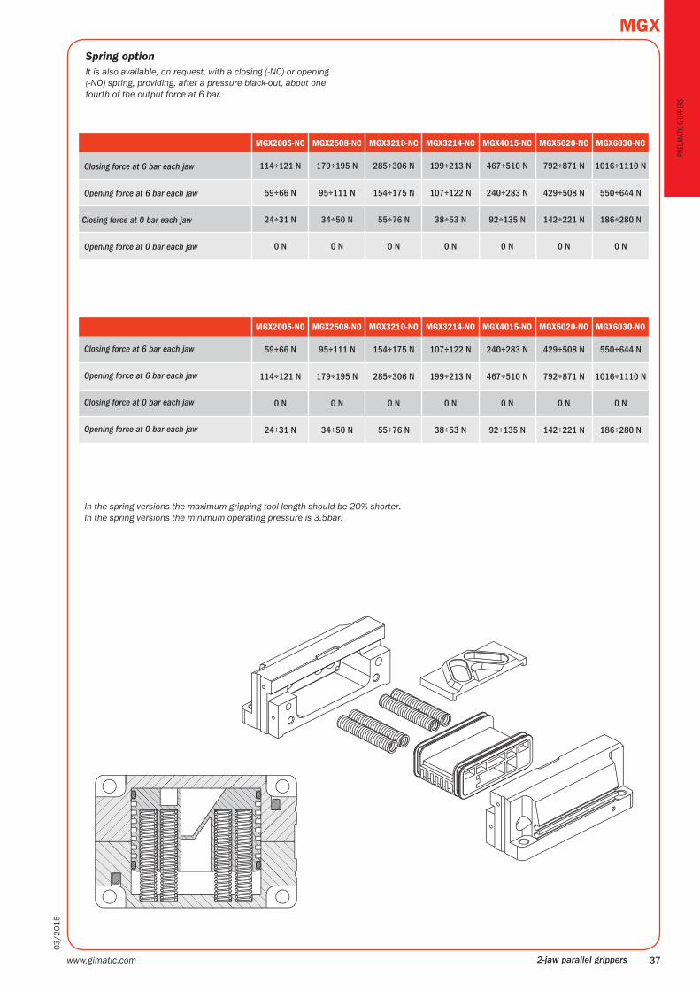
MGX2005-NC MGX2508-NC MGX3210-NC MGX3214-NC MGX4015-NC MGX5020-NC MGX6030-NC
Closing force at 6 bar each jaw 114÷121 N 179÷195 N 285÷306 N 199÷213 N 467÷510 N 792÷871 N 1016÷1110 N
Opening force at 6 bar each jaw 59÷66 N 95÷111 N 154÷175 N 107÷122 N 240÷283 N 429÷508 N 550÷644 N
Closing force at 0 bar each jaw 24÷31 N 34÷50 N 55÷76 N 38÷53 N 92÷135 N 142÷221 N 186÷280 N
Opening force at 0 bar each jaw 0 N 0 N 0 N 0 N 0 N 0 N 0 N
MGX2005-NO MGX2508-NO MGX3210-NO MGX3214-NO MGX4015-NO MGX5020-NO MGX6030-NO
Closing force at 6 bar each jaw 59÷66 N 95÷111 N 154÷175 N 107÷122 N 240÷283 N 429÷508 N 550÷644 N
Opening force at 6 bar each jaw 114÷121 N 179÷195 N 285÷306 N 199÷213 N 467÷510 N 792÷871 N 1016÷1110 N
Closing force at 0 bar each jaw 0 N 0 N 0 N 0 N 0 N 0 N 0 N
Opening force at 0 bar each jaw 24÷31 N 34÷50 N 55÷76 N 38÷53 N 92÷135 N 142÷221 N 186÷280 N
Spring optionIt is also available, on request, with a closing (-NC) or opening (-NO) spring, providing, after a pressure black-out, about one fourth of the output force at 6 bar.
In the spring versions the maximum gripping tool length should be 20% shorter.In the spring versions the minimum operating pressure is 3.5bar.

www.gimatic.com38
03
/20
15
MGXPN
EUM
ATIC
GRI
PPER
S
2-jaw parallel grippers
MGX2005 MGX2508
1 MGX2005-01 MGX2508-01Left half body 1
2 MGX2005-02 MGX2508-02Right half body 2
3 MGX2005-03 MGX2508-03Piston 3
4 MGX2005-20 MGX2508-20Slider 4
5 MGX2005-21 MGX2508-21Left jaw 5
6 MGX2005-22 MGX2508-22Right jaw 6
7 MGF2005-07 MGF2508-07Protection 7
8 MGX2005-08 MGX2508-08Ball holder 8
9 MGX2005-09 MGX2508-09Fixing plate 9
10 MGX2005-10 MGX2508-10Inductive sensor housing 10
11 MGX2005-12 MGX2508-12Spring 11
12 MGX2005-13 MGX2508-13Upper magnet housing 12
13 MGX2005-14 MGX2508-14Lower magnet housing 13
14 MGX2005-23 MGX2508-23Roller 14
15 EPP12-13 EPP12-13Magnet 15
16 Ø2 DIN5401A Ø2 DIN5401ABall 16
17 Ø3x10 mm Ø3x10 mmDowel pin 17
18 Ø2.5 DIN5401A Ø2.5 DIN5401ABall 18
19 Ø3x5.8 mm DIN5402 Ø4x7 mm DIN5402Dowel pin 19
20 M3x12 mm DIN912 INOX A2 M4x14 mm DIN912 INOX A2Screw 20
21 M2.5x10 mm DIN965A INOX A2 M2.5x10 mm DIN965A INOX A2Screw 21
22 M2x8 mm DIN7985 INOX A2 M2x8 mm DIN7985 INOX A2Screw 22
23 M3x3 mm DIN913 Z/B M3x3 mm DIN913 Z/BGrub screw 23
24 Ø1.78x17.17 HNBR (GUAR-076H) Ø1.78x23.52 HNBR (GUAR-008H)O-Ring 24
25 ZBH-5 ZBH-7Bush 25
Part list

www.gimatic.com 39
03
/20
15
MGX
PNEU
MAT
IC G
RIPP
ERS
2-jaw parallel grippers
MGX3210 MGX3214 MGX4015
1 MGX3210-01 MGX3214-01 MGX4015-01Left half body 1
2 MGX3210-02 MGX3214-02 MGX4015-02Right half body 2
3 MGX3210-03 MGX4015-03Piston 3
4 MGX3210-20 MGX3214-20 MGX4015-20Slider 4
5 MGX3210-21 MGX3214-21 MGX4015-21Left jaw 5
6 MGX3210-22 MGX3214-22 MGX4015-22Right jaw 6
7 MGX3210-07 MGX3214-07 MGF4015-07Protection 7
8 MGX3210-08 MGX4015-08Ball holder 8
9 MGX3210-09 MGX4015-09Fixing plate 9
10 MGX3210-10 MGX4015-10Inductive sensor housing 10
11 MGX3210-12 MGX4015-12Spring 11
12 MGX3210-13 MGX4015-13Upper magnet housing 12
13 MGX3210-14 MGX4015-14Lower magnet housing 13
14 MGX3210-15 MGX4015-15Upper support 14
15 MGX3210-16 MGX4015-16Lower support 15
16 - MGX4015-19Guide pin 16
17 MGX3210-23 MGX4015-23Roller 17
18 EPP12-13 R63-180-20Magnet 18
19 Ø3x12mm DIN6325 Ø4x12mm DIN6325Ball 19
20 Ø2 DIN5401ADowel pin 20
21 Ø2.5 DIN5401A Ø3 AA DIN5401ABall 21
22 Ø5x10mm DIN5402 Ø6x12mm DIN5402Dowel pin 22
23 M3x3 mm DIN913 Z/BScrew 23
24 M5x20mm DIN912 INOX A2 M5x25mm DIN912 INOX A2Screw 24
25 M2.5x10mm DIN965A INOX A2Screw 25
26 M2x8mm DIN7985 INOX A2Grub screw 26
27 Ø2.62x28.25 HNBR (GUAR-107H) MGX4015-18O-Ring 27
28 ZBH-7Bush 28
29 ZBH-7 ZBH-9Bush 29
Part list

www.gimatic.com40
03
/20
15
MGXPN
EUM
ATIC
GRI
PPER
S
2-jaw parallel grippers
MGX5020 MGX60301 MGX5020-01 MGX6030-01Left half body 1
2 MGX5020-02 MGX6030-02Right half body 2
3 MGX5020-03 MGX6025-03Piston 3
4 MGX5020-20 MGX6030-20Slider 4
5 MGX5020-21 MGX6030-21Left jaw 5
6 MGX5020-22 MGX6030-22Right jaw 6
7 MGF5020-07 MGX6030-07Protection 7
8 MGX5020-08 MGX6025-08Ball holder 8
9 MGX5020-09 MGX6030-09Fixing plate 9
10 MGX5020-10 MGX6025-10Inductive sensor housing 10
11 MGX6025-12 MGX6025-12Spring 11
12 MGX5020-13 MGX6025-13Upper magnet housing 12
13 MGX5020-14 MGX6025-14Lower magnet housing 13
14 MGX5020-15 MGX6025-15Upper support 14
15 MGX5020-16 MGX6025-16Lower support 15
16 MGX6025-19 MGX6025-19Guide pin 16
17 MGX5020-23 MGX6030-23Roller 17
18 R63-180-20 R63-180-20Magnet 18
19 Ø2.5 DIN5401A Ø2.5 DIN5401ABall 19
20 Ø3 AA DIN5401A Ø3 AA DIN5401ABall 20
21 Ø6x14 DIN6325 Ø6x14 DIN6325Dowel pin 21
22 Ø7x16 DIN5402 Ø7x14 DIN5402Dowel pin 22
23 M3x3 mm DIN913 Z/B M3x3 mm DIN913 Z/BGrub screw 23
24 M6x25 DIN912 INOX A2 M8x30 DIN912 INOX A2Screw 24
25 M2.5x10 DIN965A INOX A2 M2.5x10 DIN965A INOX A2Screw 25
26 M2.5x10 DIN912 INOX A2 M2.5x10 DIN912 INOX A2Screw 26
27 M2.9x13 DIN7982 INOX A2 M2.9x13 DIN7982 INOX A2Screw 27
28 MGX5020-18 MGX6030-18O-Ring 28
29 CUSC-029 CUSC-029Roller cage 29
30 ZBH-9 ZBH-9Bush 30
31 ZBH-12 ZBH-9Bush 31
Part list