Embed Size (px)
Citation preview
MiCOM P141, P142, P143
Technical Manual
Feeder Management Relays
Platform Hardware Version: G, J
Platform Software Version: 20, 21, 30
Publication Reference: P14x/EN T/C54
P14x/EN T/C54 © 2011. ALSTOM, the ALSTOM logo and any alternative version thereof are trademarks and service marks of ALSTOM. The other names
mentioned, registered or not, are the property of their respective companies. The technical and other data contained in this document is provided for information only.
Neither ALSTOM, its officers or employees accept responsibility for, or should be taken as making any representation or warranty (whether express or implied), as to
the accuracy or completeness of such data or the achievement of any projected performance criteria where these are indicated. ALSTOM reserves the right to revise or
change this data at any time without further notice.
GRID

Technical Guide P14x/EN T/C54 MiCOM P141, P142, P143
FEEDER MANAGEMENT RELAYS
MiCOM P141, P142, P143
CONTENT
Issue Control
Handling of Electronic Equipment
Safety Instructions
Introduction P14x/EN IT/C54
Application Notes P14x/EN AP/C54
Relay Description P14x/EN HW/C54
Technical Data P14x/EN TD/C54
SCADA Communications P14x/EN CT/C54
UCA2.0 Communications P14x/EN UC/C54
Relay Menu Database P14x/EN GC/C54
External Connection Diagrams P14x/EN CO/C54
Hardware / Software Version History and Compatibility P14x/EN VC/C54
Autoreclose Diagrams P14x/EN LG/C54

P14x/EN T/C54 Technical Guide MiCOM P141, P142, P143
Issue Control P14x/EN T/C54 MiCOM P141, P142, P143
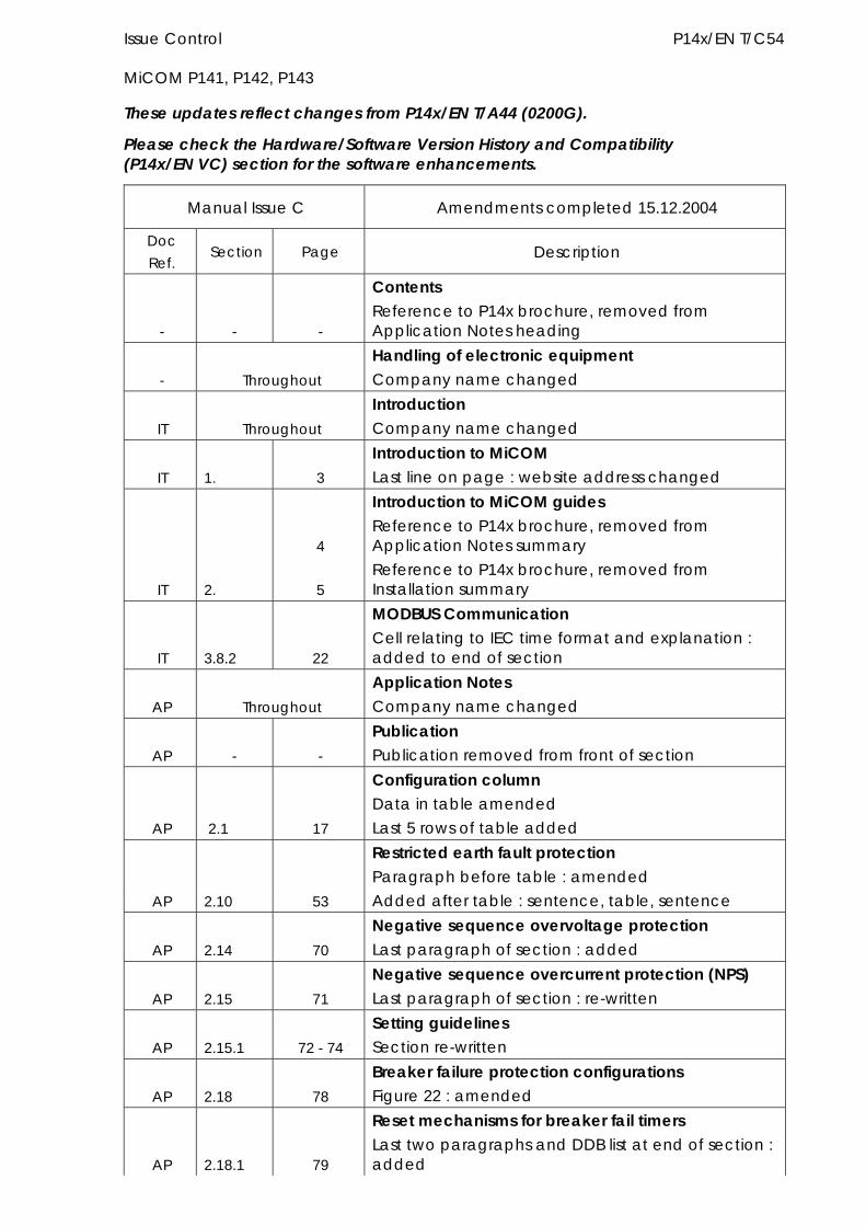
These updates reflect changes from P14x/EN T/A44 (0200G).
Please check the Hardware/Software Version History and Compatibility (P14x/EN VC) section for the software enhancements.
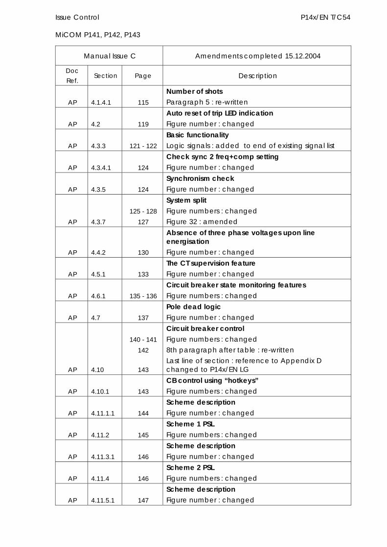
Manual Issue C Amendments completed 15.12.2004
Doc Ref.
Section Page Description
- - -
Contents Reference to P14x brochure, removed from Application Notes heading
- Throughout Handling of electronic equipment Company name changed
IT Throughout Introduction Company name changed
IT 1. 3 Introduction to MiCOM Last line on page : website address changed
4
Introduction to MiCOM guides Reference to P14x brochure, removed from Application Notes summary
IT 2. 5 Reference to P14x brochure, removed from Installation summary
IT 3.8.2 22
MODBUS Communication Cell relating to IEC time format and explanation : added to end of section
AP Throughout Application Notes Company name changed
AP - - Publication Publication removed from front of section
Configuration column Data in table amended
AP 2.1 17 Last 5 rows of table added
Restricted earth fault protection Paragraph before table : amended
AP 2.10 53 Added after table : sentence, table, sentence
AP 2.14 70 Negative sequence overvoltage protection Last paragraph of section : added
AP 2.15 71 Negative sequence overcurrent protection (NPS) Last paragraph of section : re-written
AP 2.15.1 72 - 74 Setting guidelines Section re-written
AP 2.18 78 Breaker failure protection configurations Figure 22 : amended
AP 2.18.1 79
Reset mechanisms for breaker fail timers Last two paragraphs and DDB list at end of section : added
P14x/EN T/C54 Issue Control MiCOM P141, P142, P143
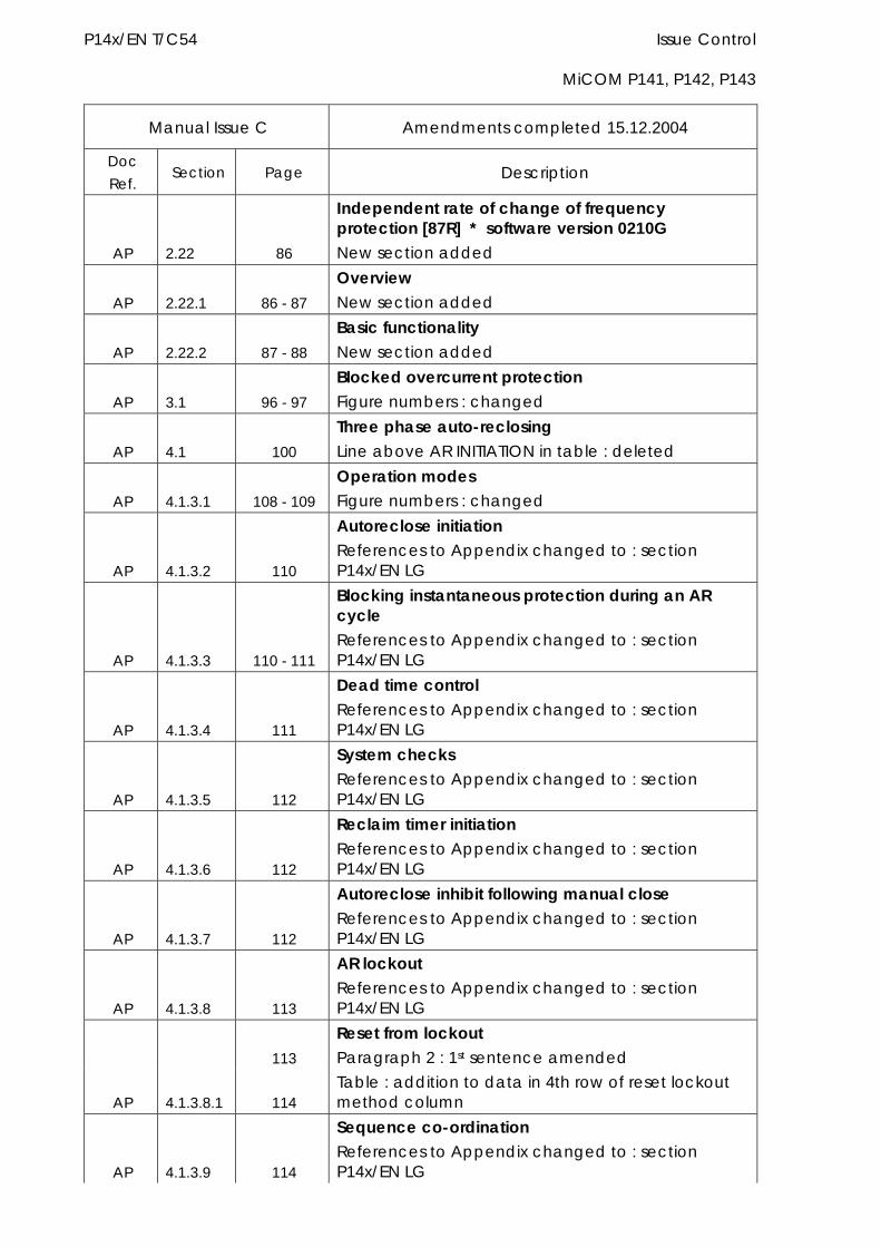
Manual Issue C Amendments completed 15.12.2004
Doc Ref.
Section Page Description
AP 2.22 86
Independent rate of change of frequency protection [87R] * software version 0210G New section added
AP 2.22.1 86 - 87 Overview New section added
AP 2.22.2 87 - 88 Basic functionality New section added
AP 3.1 96 - 97 Blocked overcurrent protection Figure numbers : changed
AP 4.1 100 Three phase auto-reclosing Line above AR INITIATION in table : deleted
AP 4.1.3.1 108 - 109 Operation modes Figure numbers : changed
AP 4.1.3.2 110
Autoreclose initiation References to Appendix changed to : section P14x/EN LG
AP 4.1.3.3 110 - 111
Blocking instantaneous protection during an AR cycle References to Appendix changed to : section P14x/EN LG
AP 4.1.3.4 111
Dead time control References to Appendix changed to : section P14x/EN LG
AP 4.1.3.5 112
System checks References to Appendix changed to : section P14x/EN LG
AP 4.1.3.6 112
Reclaim timer initiation References to Appendix changed to : section P14x/EN LG
AP 4.1.3.7 112
Autoreclose inhibit following manual close References to Appendix changed to : section P14x/EN LG
AP 4.1.3.8 113
AR lockout References to Appendix changed to : section P14x/EN LG
113 Reset from lockout Paragraph 2 : 1st sentence amended
AP 4.1.3.8.1 114 Table : addition to data in 4th row of reset lockout method column
AP 4.1.3.9 114
Sequence co-ordination References to Appendix changed to : section P14x/EN LG
Issue Control P14x/EN T/C54 MiCOM P141, P142, P143
Manual Issue C Amendments completed 15.12.2004
Doc Ref.
Section Page Description
AP 4.1.4.1 115 Number of shots Paragraph 5 : re-written
AP 4.2 119 Auto reset of trip LED indication Figure number : changed
AP 4.3.3 121 - 122 Basic functionality Logic signals : added to end of existing signal list
AP 4.3.4.1 124 Check sync 2 freq+comp setting Figure number : changed
AP 4.3.5 124 Synchronism check Figure number : changed
125 - 128 System split Figure numbers : changed
AP 4.3.7 127 Figure 32 : amended
AP 4.4.2 130
Absence of three phase voltages upon line energisation Figure number : changed
AP 4.5.1 133 The CT supervision feature Figure number : changed
AP 4.6.1 135 - 136 Circuit breaker state monitoring features Figure numbers : changed
AP 4.7 137 Pole dead logic Figure number : changed
140 - 141 Circuit breaker control Figure numbers : changed
142 8th paragraph after table : re-written
AP 4.10 143 Last line of section : reference to Appendix D changed to P14x/EN LG
AP 4.10.1 143 CB control using “hotkeys” Figure numbers : changed
AP 4.11.1.1 144 Scheme description Figure number : changed
AP 4.11.2 145 Scheme 1 PSL Figure numbers : changed
AP 4.11.3.1 146 Scheme description Figure number : changed
AP 4.11.4 146 Scheme 2 PSL Figure numbers : changed
AP 4.11.5.1 147 Scheme description Figure number : changed
P14x/EN T/C54 Issue Control MiCOM P141, P142, P143
Manual Issue C Amendments completed 15.12.2004
Doc Ref.
Section Page Description
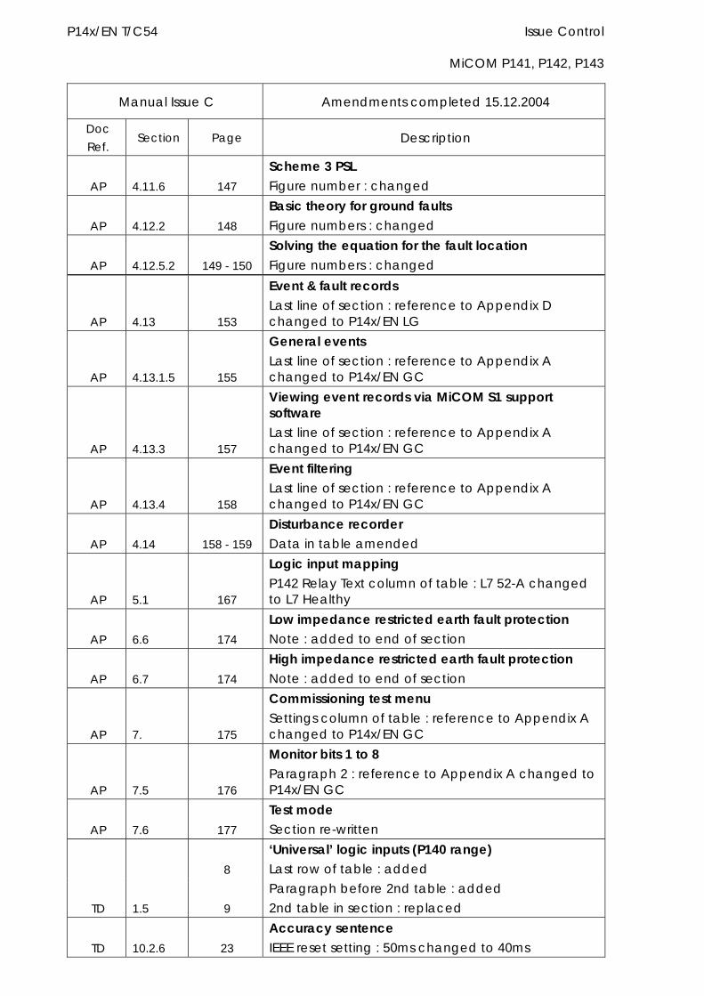
AP 4.11.6 147 Scheme 3 PSL Figure number : changed
AP 4.12.2 148 Basic theory for ground faults Figure numbers : changed
AP 4.12.5.2 149 - 150 Solving the equation for the fault location Figure numbers : changed
AP 4.13 153
Event & fault records Last line of section : reference to Appendix D changed to P14x/EN LG
AP 4.13.1.5 155
General events Last line of section : reference to Appendix A changed to P14x/EN GC
AP 4.13.3 157
Viewing event records via MiCOM S1 support software Last line of section : reference to Appendix A changed to P14x/EN GC
AP 4.13.4 158
Event filtering Last line of section : reference to Appendix A changed to P14x/EN GC
AP 4.14 158 - 159 Disturbance recorder Data in table amended
AP 5.1 167
Logic input mapping P142 Relay Text column of table : L7 52-A changed to L7 Healthy
AP 6.6 174 Low impedance restricted earth fault protection Note : added to end of section
AP 6.7 174 High impedance restricted earth fault protection Note : added to end of section
AP 7. 175
Commissioning test menu Settings column of table : reference to Appendix A changed to P14x/EN GC
AP 7.5 176
Monitor bits 1 to 8 Paragraph 2 : reference to Appendix A changed to P14x/EN GC
AP 7.6 177 Test mode Section re-written
8 ‘Universal’ logic inputs (P140 range) Last row of table : added
TD 1.5 9 Paragraph before 2nd table : added 2nd table in section : replaced
TD 10.2.6 23 Accuracy sentence IEEE reset setting : 50ms changed to 40ms
Issue Control P14x/EN T/C54 MiCOM P141, P142, P143
Manual Issue C Amendments completed 15.12.2004
Doc Ref.
Section Page Description
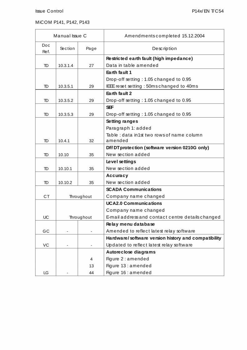
TD 10.3.1.4 27 Restricted earth fault (high impedance) Data in table amended
TD 10.3.5.1 29
Earth fault 1 Drop-off setting : 1.05 changed to 0.95 IEEE reset setting : 50ms changed to 40ms
TD 10.3.5.2 29 Earth fault 2 Drop-off setting : 1.05 changed to 0.95
TD 10.3.5.3 29 SEF Drop-off setting : 1.05 changed to 0.95
TD 10.4.1 32
Setting ranges Paragraph 1: added Table : data in1st two rows of name column amended
TD 10.10 35 DF/DT protection (software version 0210G only) New section added
TD 10.10.1 35 Level settings New section added
TD 10.10.2 35 Accuracy New section added
CT Throughout SCADA Communications Company name changed
UC Throughout
UCA2.0 Communications Company name changed E-mail address and contact centre details changed
GC - - Relay menu database Amended to reflect latest relay software
VC - - Hardware/software version history and compatibility Updated to reflect latest relay software
4 Autoreclose diagrams Figure 2 : amended
13 Figure 13 : amended LG - 44 Figure 16 : amended

P14x/EN T/C54 Issue Control MiCOM P141, P142, P143
HANDLING OF ELECTRONIC EQUIPMENT A person’s normal movements can easily generate electrostatic potentials of several thousand volts. Discharge of these voltages into semiconductor devices when handling circuits can cause serious damage, which often may not be immediately apparent but the reliability of the circuit will have been reduced.
The electronic circuits of ALSTOM Grid are immune to the relevant levels of electrostatic discharge when housed in their cases. Do not expose them to the risk of damage by withdrawing modules unnecessarily.
Each module incorporates the highest practicable protection for its semiconductor devices. However, if it becomes necessary to withdraw a module, the following precautions should be taken to preserve the high reliability and long life for which the equipment has been designed and manufactured.
1. Before removing a module, ensure that you are a same electrostatic potential as the equipment by touching the case.
2. Handle the module by its front-plate, frame, or edges of the printed circuit board. Avoid touching the electronic components, printed circuit track or connectors.
3. Do not pass the module to any person without first ensuring that you are both at the same electrostatic potential. Shaking hands achieves equipotential.
4. Place the module on an antistatic surface, or on a conducting surface which is at the same potential as yourself.
5. Store or transport the module in a conductive bag.
More information on safe working procedures for all electronic equipment can be found in BS5783 and IEC 60147-0F.
If you are making measurements on the internal electronic circuitry of an equipment in service, it is preferable that you are earthed to the case with a conductive wrist strap.
Wrist straps should have a resistance to ground between 500k – 10M ohms. If a wrist strap is not available you should maintain regular contact with the case to prevent the build up of static. Instrumentation which may be used for making measurements should be earthed to the case whenever possible.
ALSTOM Grid strongly recommends that detailed investigations on the electronic circuitry, or modification work, should be carried out in a Special Handling Area such as described in BS5783 or IEC 60147-0F.


SAFETY SECTION

CONTENT
1. SAFETY SECTION 3 1.1 Health and safety 3
1.2 Explanation of symbols and labels 3
2. INSTALLING, COMMISSIONING AND SERVICING 3
3. EQUIPMENT OPERATING CONDITIONS 4 3.1 Current transformer circuits 4
3.2 External resistors 4
3.3 Battery replacement 4
3.4 Insulation and dielectric strength testing 4
3.5 Insertion of modules and pcb cards 4
3.6 Fibre optic communication 5
4. OLDER PRODUCTS 5
5. DECOMMISSIONING AND DISPOSAL 5
6. TECHNICAL SPECIFICATIONS 6

1. SAFETY SECTION
This Safety Section should be read before commencing any work on the equipment.
1.1 Health and safety The information in the Safety Section of the product documentation is intended to ensure that products are properly installed and handled in order to maintain them in a safe condition. It is assumed that everyone who will be associated with the equipment will be familiar with the contents of the Safety Section.
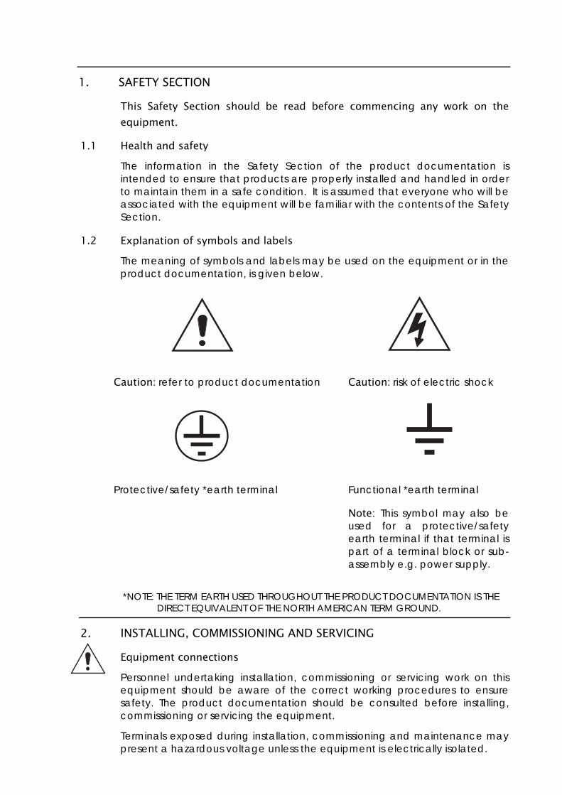
1.2 Explanation of symbols and labels The meaning of symbols and labels may be used on the equipment or in the product documentation, is given below.
Caution: refer to product documentation Caution: risk of electric shock
Protective/safety *earth terminal Functional *earth terminal
Note: This symbol may also be used for a protective/safety earth terminal if that terminal is part of a terminal block or sub-assembly e.g. power supply.
*NOTE: THE TERM EARTH USED THROUGHOUT THE PRODUCT DOCUMENTATION IS THE DIRECT EQUIVALENT OF THE NORTH AMERICAN TERM GROUND.
2. INSTALLING, COMMISSIONING AND SERVICING
Equipment connections Personnel undertaking installation, commissioning or servicing work on this equipment should be aware of the correct working procedures to ensure safety. The product documentation should be consulted before installing, commissioning or servicing the equipment.
Terminals exposed during installation, commissioning and maintenance may present a hazardous voltage unless the equipment is electrically isolated.
If there is unlocked access to the rear of the equipment, care should be taken by all personnel to avoid electrical shock or energy hazards.
Voltage and current connections should be made using insulated crimp terminations to ensure that terminal block insulation requirements are maintained for safety. To ensure that wires are correctly terminated, the correct crimp terminal and tool for the wire size should be used.
Before energising the equipment it must be earthed using the protective earth terminal, or the appropriate termination of the supply plug in the case of plug connected equipment. Omitting or disconnecting the equipment earth may cause a safety hazard.
The recommended minimum earth wire size is 2.5mm2, unless otherwise stated in the technical data section of the product documentation.
Before energising the equipment, the following should be checked:
Voltage rating and polarity;
CT circuit rating and integrity of connections;
Protective fuse rating;
Integrity of earth connection (where applicable)
Remove front plate plastic film protection
Remove insulating strip from battery compartment
3. EQUIPMENT OPERATING CONDITIONS The equipment should be operated within the specified electrical and environmental limits.
3.1 Current transformer circuits Do not open the secondary circuit of a live CT since the high level voltage produced may be lethal to personnel and could damage insulation.
3.2 External resistors Where external resistors are fitted to relays, these may present a risk of electric shock or burns, if touched.
3.3 Battery replacement Where internal batteries are fitted they should be replaced with the recommended type and be installed with the correct polarity, to avoid possible damage to the equipment.
3.4 Insulation and dielectric strength testing Insulation testing may leave capacitors charged up to a hazardous voltage. At the end of each part of the test, the voltage should be gradually reduced to zero, to discharge capacitors, before the test leads are disconnected.
3.5 Insertion of modules and pcb cards These must not be inserted into or withdrawn from equipment whist it is energised since this may result in damage.
3.6 Fibre optic communication Where fibre optic communication devices are fitted, these should not be viewed directly. Optical power meters should be used to determine the operation or signal level of the device.
4. OLDER PRODUCTS
Electrical adjustments Equipments which require direct physical adjustments to their operating mechanism to change current or voltage settings, should have the electrical power removed before making the change, to avoid any risk of electrical shock.
Mechanical adjustments The electrical power to the relay contacts should be removed before checking any mechanical settings, to avoid any risk of electric shock.
Draw out case relays Removal of the cover on equipment incorporating electromechanical operating elements, may expose hazardous live parts such as relay contacts.
Insertion and withdrawal of extender cards When using an extender card, this should not be inserted or withdrawn from the equipment whilst it is energised. This is to avoid possible shock or damage hazards. Hazardous live voltages may be accessible on the extender card.
Insertion and withdrawal of heavy current test plugs When using a heavy current test plug, CT shorting links must be in place before insertion or removal, to avoid potentially lethal voltages.
5. DECOMMISSIONING AND DISPOSAL
Decommissioning: The auxiliary supply circuit in the relay may include capacitors across the supply or to earth. To avoid electric shock or energy hazards, after completely isolating the supplies to the relay (both poles of any dc supply), the capacitors should be safely discharged via the external terminals prior to decommissioning.
Disposal: It is recommended that incineration and disposal to water courses is avoided. The product should be disposed of in a safe manner. Any products containing batteries should have them removed before disposal, taking precautions to avoid short circuits. Particular regulations within the country of operation, may apply to the disposal of lithium batteries.
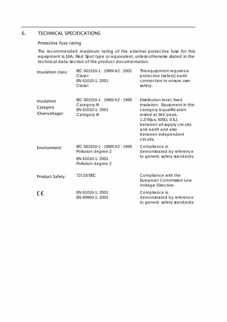
6. TECHNICAL SPECIFICATIONS
Protective fuse rating The recommended maximum rating of the external protective fuse for this equipment is 16A, Red Spot type or equivalent, unless otherwise stated in the technical data section of the product documentation.
Insulation class: IEC 601010-1 : 1990/A2 : 2001 Class I EN 61010-1: 2001 Class I
This equipment requires a protective (safety) earth connection to ensure user safety.
Insulation Category (Overvoltage):
IEC 601010-1 : 1990/A2 : 1995 Category III EN 61010-1: 2001 Category III
Distribution level, fixed insulation. Equipment in this category is qualification tested at 5kV peak, 1.2/50s, 5000.5J, between all supply circuits and earth and also between independent circuits.
Environment: IEC 601010-1 : 1990/A2 : 1995 Pollution degree 2
EN 61010-1: 2001 Pollution degree 2
Compliance is demonstrated by reference to generic safety standards.
Product Safety:
72/23/EEC
EN 61010-1: 2001 EN 60950-1: 2002
Compliance with the European Commission Low Voltage Directive.
Compliance is demonstrated by reference to generic safety standards.

Introduction P14x/EN IT/C54 MiCOM P141, P142, P143
INTRODUCTION

P14x/EN IT/C54 Introduction MiCOM P141, P142, P143
Introduction P14x/EN IT/C54 MiCOM P141, P142, P143 Page 1/30
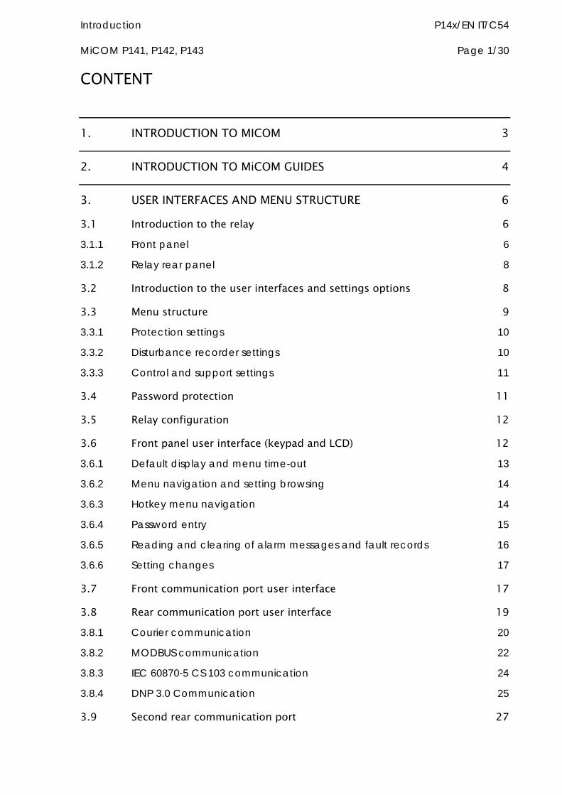
CONTENT
1. INTRODUCTION TO MICOM 3
2. INTRODUCTION TO MiCOM GUIDES 4
3. USER INTERFACES AND MENU STRUCTURE 6
3.1 Introduction to the relay 6 3.1.1 Front panel 6
3.1.2 Relay rear panel 8
3.2 Introduction to the user interfaces and settings options 8
3.3 Menu structure 9 3.3.1 Protection settings 10
3.3.2 Disturbance recorder settings 10
3.3.3 Control and support settings 11
3.4 Password protection 11
3.5 Relay configuration 12
3.6 Front panel user interface (keypad and LCD) 12 3.6.1 Default display and menu time-out 13
3.6.2 Menu navigation and setting browsing 14
3.6.3 Hotkey menu navigation 14
3.6.4 Password entry 15
3.6.5 Reading and clearing of alarm messages and fault records 16
3.6.6 Setting changes 17
3.7 Front communication port user interface 17
3.8 Rear communication port user interface 19 3.8.1 Courier communication 20
3.8.2 MODBUS communication 22
3.8.3 IEC 60870-5 CS 103 communication 24
3.8.4 DNP 3.0 Communication 25
3.9 Second rear communication port 27
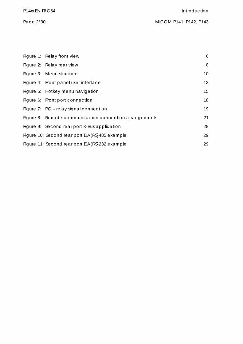
P14x/EN IT/C54 Introduction Page 2/30 MiCOM P141, P142, P143
Figure 1: Relay front view 6
Figure 2: Relay rear view 8
Figure 3: Menu structure 10
Figure 4: Front panel user interface 13
Figure 5: Hotkey menu navigation 15
Figure 6: Front port connection 18
Figure 7: PC – relay signal connection 19
Figure 8: Remote communication connection arrangements 21
Figure 9: Second rear port K-Bus application 28
Figure 10: Second rear port EIA(RS)485 example 29
Figure 11: Second rear port EIA(RS)232 example 29

Introduction P14x/EN IT/C54 MiCOM P141, P142, P143 Page 3/30
1. INTRODUCTION TO MICOM MiCOM is a comprehensive solution capable of meeting all electricity supply requirements. It comprises a range of components, systems and services from ALSTOM Grid.
Central to the MiCOM concept is flexibility.
MiCOM provides the ability to define an application solution and, through extensive communication capabilities, to integrate it with your power supply control system.
The components within MiCOM are:
P range protection relays;
C range control products;
M range measurement products for accurate metering and monitoring;
S range versatile PC support and substation control packages.
MiCOM products include extensive facilities for recording information on the state and behaviour of the power system using disturbance and fault records. They can also provide measurements of the system at regular intervals to a control centre enabling remote monitoring and control to take place.
For up-to-date information on any MiCOM product, visit our website:
http://www.alstom.com/grid/sas/
P14x/EN IT/C54 Introduction Page 4/30 MiCOM P141, P142, P143
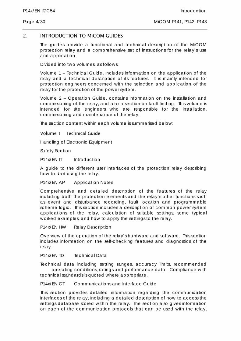
2. INTRODUCTION TO MiCOM GUIDES The guides provide a functional and technical description of the MiCOM protection relay and a comprehensive set of instructions for the relay’s use and application.
Divided into two volumes, as follows:
Volume 1 – Technical Guide, includes information on the application of the relay and a technical description of its features. It is mainly intended for protection engineers concerned with the selection and application of the relay for the protection of the power system.
Volume 2 – Operation Guide, contains information on the installation and commissioning of the relay, and also a section on fault finding. This volume is intended for site engineers who are responsible for the installation, commissioning and maintenance of the relay.
The section content within each volume is summarised below:
Volume 1 Technical Guide Handling of Electronic Equipment
Safety Section
P14x/EN IT Introduction
A guide to the different user interfaces of the protection relay describing how to start using the relay.
P14x/EN AP Application Notes
Comprehensive and detailed description of the features of the relay including both the protection elements and the relay’s other functions such as event and disturbance recording, fault location and programmable scheme logic. This section includes a description of common power system applications of the relay, calculation of suitable settings, some typical worked examples, and how to apply the settings to the relay.
P14x/EN HW Relay Description
Overview of the operation of the relay’s hardware and software. This section includes information on the self-checking features and diagnostics of the relay.
P14x/EN TD Technical Data
Technical data including setting ranges, accuracy limits, recommended operating conditions, ratings and performance data. Compliance with technical standards is quoted where appropriate.
P14x/EN CT Communications and Interface Guide
This section provides detailed information regarding the communication interfaces of the relay, including a detailed description of how to access the settings database stored within the relay. The section also gives information on each of the communication protocols that can be used with the relay,
Introduction P14x/EN IT/C54 MiCOM P141, P142, P143 Page 5/30
and is intended to allow the user to design a custom interface to a SCADA system.
P14x/EN GC Relay Menu Database: User interface/Courier/MODBUS/IEC 60870-5-103/DNP 3.0
Listing of all of the settings contained within the relay together with a brief description of each.
P14x/EN CO External Connection Diagrams
All external wiring connections to the relay.
P14x/EN VC Hardware / Software Version History and Compatibility
P14x/EN LG Auto-reclose Logic Diagrams
Volume 2 Operation Guide Handling of Electronic Equipment
Safety Section
P14x/EN IT Introduction
A guide to the different user interfaces of the protection relay describing how to start using the relay.
P14x/EN IN Installation
Recommendations on unpacking, handling, inspection and storage of the relay. A guide to the mechanical and electrical installation of the relay is provided incorporating earthing recommendations.
P14x/EN CM Commissioning and Maintenance
Instructions on how to commission the relay, comprising checks on the calibration and functionality of the relay. A general maintenance policy for the relay is outlined.
P14x/EN PR Problem Analysis
Advice on how to recognise failure modes and the recommended course of action.
P14x/EN GC Relay Menu Database: User interface/Courier/MODBUS/ IEC 60870-5-103/DNP 3.0
Listing of all of the settings contained within the relay together with a brief description of each.
P14x/EN CO External Connection Diagrams
All external wiring connections to the relay.
P14x/EN VC Hardware / Software Version History and Compatibility
Repair Form
P14x/EN IT/C54 Introduction Page 6/30 MiCOM P141, P142, P143
3. USER INTERFACES AND MENU STRUCTURE The settings and functions of the MiCOM protection relay can be accessed both from the front panel keypad and LCD, and via the front and rear communication ports. Information on each of these methods is given in this section to describe how to get started using the relay.
3.1 Introduction to the relay 3.1.1 Front panel
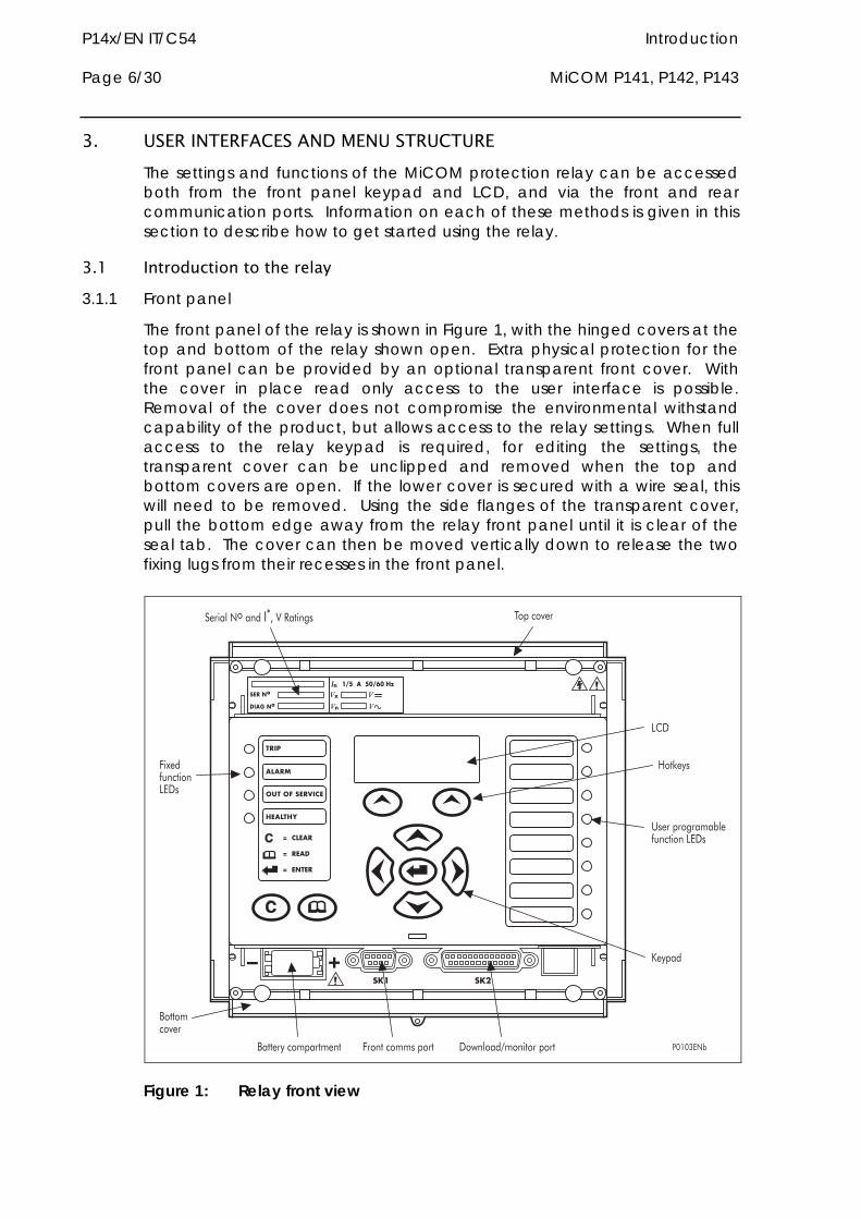
The front panel of the relay is shown in Figure 1, with the hinged covers at the top and bottom of the relay shown open. Extra physical protection for the front panel can be provided by an optional transparent front cover. With the cover in place read only access to the user interface is possible. Removal of the cover does not compromise the environmental withstand capability of the product, but allows access to the relay settings. When full access to the relay keypad is required, for editing the settings, the transparent cover can be unclipped and removed when the top and bottom covers are open. If the lower cover is secured with a wire seal, this will need to be removed. Using the side flanges of the transparent cover, pull the bottom edge away from the relay front panel until it is clear of the seal tab. The cover can then be moved vertically down to release the two fixing lugs from their recesses in the front panel.
����������� ��������������
����
�����
���� ������
�������
��������
�������
��������
�����
�������
������
��
����������������
���� ������������������ ������ ��
!�"��������������
#������� ��
#����$����������� !��������������� ��%� ��&������������
'�$��
�(�
��������
)��*�$�
Figure 1: Relay front view
Introduction P14x/EN IT/C54 MiCOM P141, P142, P143 Page 7/30
Note: *May vary according to relay type/model
The front panel of the relay includes the following, as indicated in Figure 1:
a 16-character by 3-line alphanumeric liquid crystal display (LCD).
a 9-key keypad comprising 4 arrow keys , and ), an enter key (), a clear key (), a read key () and 2 additional hot keys (.
Hotkey functionality:
SCROLL Starts scrolling through the various default displays.
STOP Stops scrolling the default display
for control of setting groups, control inputs and circuit breaker operation*.
12 LEDs; 4 fixed function LEDs on the left hand side of the front panel and 8 programmable function LEDs on the right hand side.
Under the top hinged cover:
the relay serial number, and the relay’s current and voltage rating information*.
Under the bottom hinged cover:
battery compartment to hold the 1/2 AA size battery which is used for memory back-up for the real time clock, event, fault and disturbance records.
a 9-pin female D-type front port for communication with a PC locally to the relay (up to 15m distance) via an EIA(RS)232 serial data connection.
a 25-pin female D-type port providing internal signal monitoring and high speed local downloading of software and language text via a parallel data connection.
The fixed function LEDs on the left hand side of the front panel are used to indicate the following conditions:
Trip (Red) indicates that the relay has issued a trip signal. It is reset when the associated fault record is cleared from the front display. (Alternatively the trip LED can be configured to be self-resetting)*.
Alarm (Yellow) flashes to indicate that the relay has registered an alarm. This may be triggered by a fault, event or maintenance record. The LED will flash until the alarms have been accepted (read), after which the LED will change to constant illumination, and will extinguish when the alarms have been cleared.
Out of service (Yellow) indicates that the relay’s protection is unavailable.
Healthy (Green) indicates that the relay is in correct working order, and should be on at all times. It will be extinguished if the relay’s self-test facilities indicate that there is an error with the relay’s hardware or software. The
P14x/EN IT/C54 Introduction Page 8/30 MiCOM P141, P142, P143
state of the healthy LED is reflected by the watchdog contact at the back of the relay.
To improve the visibility of the settings via the front panel, the LCD contrast can be adjusted using the “LCD Contrast” setting in the CONFIGURATION column.
3.1.2 Relay rear panel
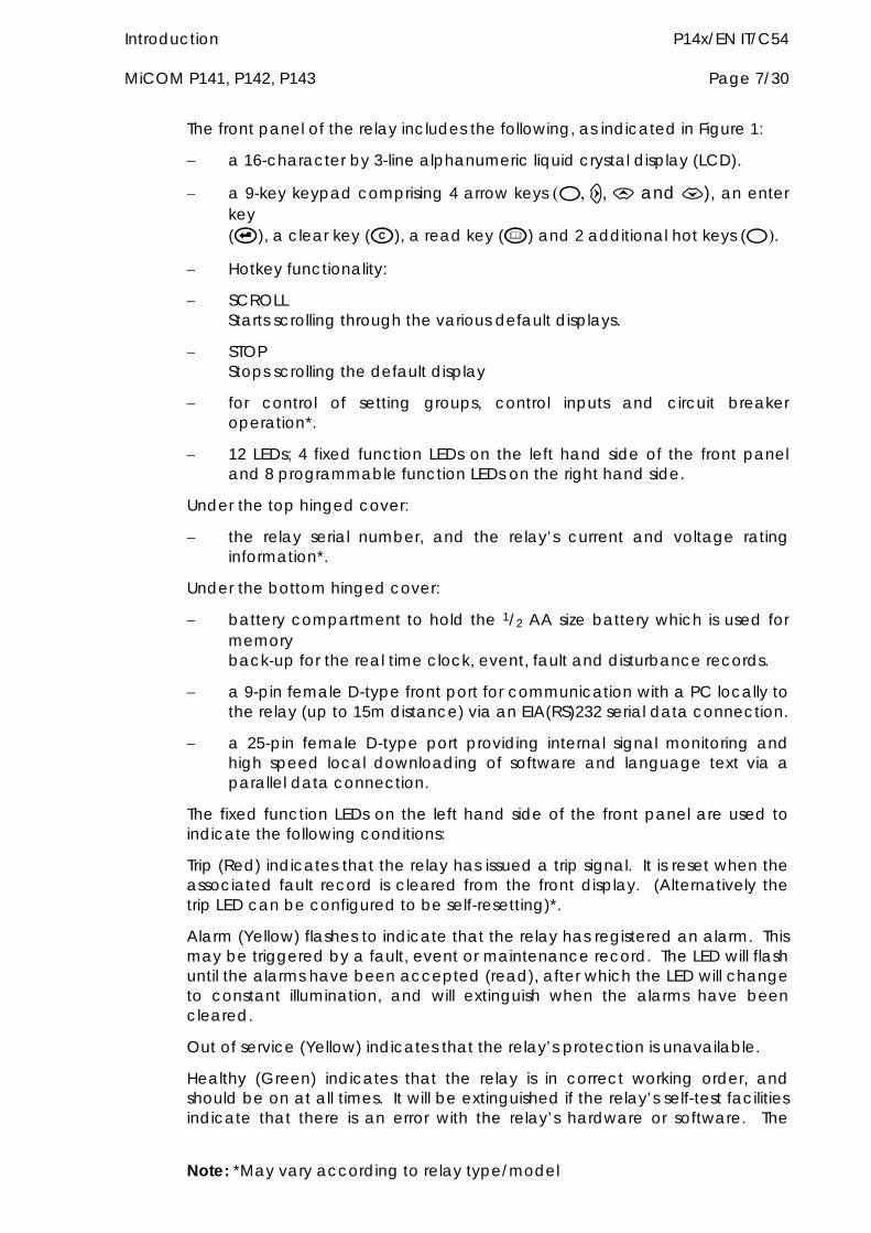
The rear panel of the relay is shown in Figure 2. All current and voltage signals*, digital logic input signals and output contacts are connected at the rear of the relay. Also connected at the rear is the twisted pair wiring for the rear EIA(RS)485 communication port, the IRIG-B time synchronising input and the optical fibre rear communication port which are both optional.
� � �� �
������
�!
������
�!
+����� ����,-#����� ��� ������������������
(����������� � �������������� �
���� �������.�� $�/������������
��������������.��012/
3�%������� $����������
34540��
Figure 2: Relay rear view
Refer to the wiring diagram in section P14x/EN CO for complete connection details.
3.2 Introduction to the user interfaces and settings options The relay has three user interfaces:
the front panel user interface via the LCD and keypad.
Note: *May vary according to relay type/model
Introduction P14x/EN IT/C54 MiCOM P141, P142, P143 Page 9/30
Note: *May vary according to relay type/model
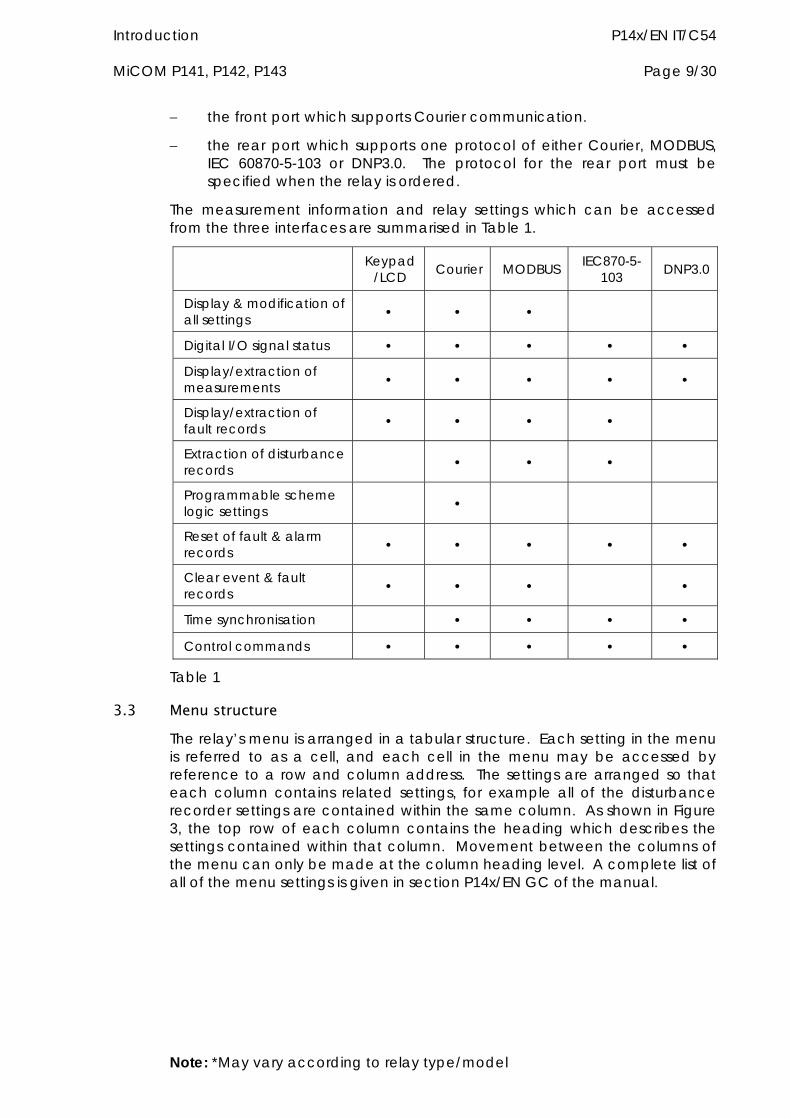
the front port which supports Courier communication.
the rear port which supports one protocol of either Courier, MODBUS, IEC 60870-5-103 or DNP3.0. The protocol for the rear port must be specified when the relay is ordered.
The measurement information and relay settings which can be accessed from the three interfaces are summarised in Table 1.
Keypad/LCD Courier MODBUS IEC870-5-
103 DNP3.0
Display & modification of all settings • • •
Digital I/O signal status • • • • •
Display/extraction of measurements • • • • •
Display/extraction of fault records • • • •
Extraction of disturbance records • • •
Programmable scheme logic settings •
Reset of fault & alarm records • • • • •
Clear event & fault records • • • •
Time synchronisation • • • •
Control commands • • • • •
Table 1
3.3 Menu structure The relay’s menu is arranged in a tabular structure. Each setting in the menu is referred to as a cell, and each cell in the menu may be accessed by reference to a row and column address. The settings are arranged so that each column contains related settings, for example all of the disturbance recorder settings are contained within the same column. As shown in Figure 3, the top row of each column contains the heading which describes the settings contained within that column. Movement between the columns of the menu can only be made at the column heading level. A complete list of all of the menu settings is given in section P14x/EN GC of the manual.
P14x/EN IT/C54 Introduction Page 10/30 MiCOM P141, P142, P143
������0������������������������
(� �����
�������
(� ����6����
(����� �7�������� ,�����5 ,�����8
�$������� ���%�������� + ��������� ,�������� � + ��������� ,�������� �
������������������8��9����0
3454:��
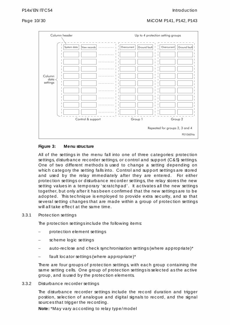
Figure 3: Menu structure
All of the settings in the menu fall into one of three categories: protection settings, disturbance recorder settings, or control and support (C&S) settings. One of two different methods is used to change a setting depending on which category the setting falls into. Control and support settings are stored and used by the relay immediately after they are entered. For either protection settings or disturbance recorder settings, the relay stores the new setting values in a temporary ‘scratchpad’. It activates all the new settings together, but only after it has been confirmed that the new settings are to be adopted. This technique is employed to provide extra security, and so that several setting changes that are made within a group of protection settings will all take effect at the same time.
3.3.1 Protection settings
The protection settings include the following items:
protection element settings
scheme logic settings
auto-reclose and check synchronisation settings (where appropriate)*
fault locator settings (where appropriate)*
There are four groups of protection settings, with each group containing the same setting cells. One group of protection settings is selected as the active group, and is used by the protection elements.
3.3.2 Disturbance recorder settings
The disturbance recorder settings include the record duration and trigger position, selection of analogue and digital signals to record, and the signal sources that trigger the recording. Note: *May vary according to relay type/model
Introduction P14x/EN IT/C54 MiCOM P141, P142, P143 Page 11/30
Note: *May vary according to relay type/model
3.3.3 Control and support settings
The control and support settings include:
relay configuration settings
open/close circuit breaker*
CT & VT ratio settings*
reset LEDs
active protection setting group
password & language settings
circuit breaker control & monitoring settings*
communications settings
measurement settings
event & fault record settings
user interface settings
commissioning settings
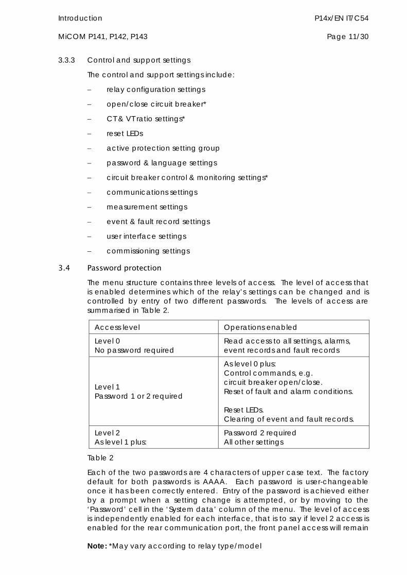
3.4 Password protection The menu structure contains three levels of access. The level of access that is enabled determines which of the relay’s settings can be changed and is controlled by entry of two different passwords. The levels of access are summarised in Table 2.
Access level Operations enabled
Level 0 No password required
Read access to all settings, alarms, event records and fault records
Level 1 Password 1 or 2 required
As level 0 plus: Control commands, e.g. circuit breaker open/close. Reset of fault and alarm conditions. Reset LEDs. Clearing of event and fault records.
Level 2 As level 1 plus:
Password 2 required All other settings
Table 2
Each of the two passwords are 4 characters of upper case text. The factory default for both passwords is AAAA. Each password is user-changeable once it has been correctly entered. Entry of the password is achieved either by a prompt when a setting change is attempted, or by moving to the ‘Password’ cell in the ‘System data’ column of the menu. The level of access is independently enabled for each interface, that is to say if level 2 access is enabled for the rear communication port, the front panel access will remain
P14x/EN IT/C54 Introduction Page 12/30 MiCOM P141, P142, P143
Note: *May vary according to relay type/model
at level 0 unless the relevant password is entered at the front panel. The access level enabled by the password entry will time-out independently for each interface after a period of inactivity and revert to the default level. If the passwords are lost an emergency password can be supplied - contact ALSTOM Grid with the relay’s serial number. The current level of access enabled for an interface can be determined by examining the 'Access level' cell in the 'System data' column, the access level for the front panel User Interface (UI), can also be found as one of the default display options.
The relay is supplied with a default access level of 2, such that no password is required to change any of the relay settings. It is also possible to set the default menu access level to either level 0 or level 1, preventing write access to the relay settings without the correct password. The default menu access level is set in the ‘Password control’ cell which is found in the ‘System data’ column of the menu (note that this setting can only be changed when level 2 access is enabled).
3.5 Relay configuration The relay is a multi-function device which supports numerous different protection, control and communication features. In order to simplify the setting of the relay, there is a configuration settings column which can be used to enable or disable many of the functions of the relay. The settings associated with any function that is disabled are made invisible, i.e. they are not shown in the menu. To disable a function change the relevant cell in the ‘Configuration’ column from ‘Enabled’ to ‘Disabled’.
The configuration column controls which of the four protection settings groups is selected as active through the ‘Active settings’ cell. A protection setting group can also be disabled in the configuration column, provided it is not the present active group. Similarly, a disabled setting group cannot be set as the active group.
The column also allows all of the setting values in one group of protection settings to be copied to another group.
To do this firstly set the ‘Copy from’ cell to the protection setting group to be copied, then set the ‘Copy to’ cell to the protection group where the copy is to be placed. The copied settings are initially placed in the temporary scratchpad, and will only be used by the relay following confirmation.
To restore the default values to the settings in any protection settings group, set the ‘Restore defaults’ cell to the relevant group number. Alternatively it is possible to set the ‘Restore defaults’ cell to ‘All settings’ to restore the default values to all of the relay’s settings, not just the protection groups’ settings. The default settings will initially be placed in the scratchpad and will only be used by the relay after they have been confirmed. Note that restoring defaults to all settings includes the rear communication port settings, which may result in communication via the rear port being disrupted if the new (default) settings do not match those of the master station.
3.6 Front panel user interface (keypad and LCD) When the keypad is exposed it provides full access to the menu options of the relay, with the information displayed on the LCD.
Introduction P14x/EN IT/C54 MiCOM P141, P142, P143 Page 13/30
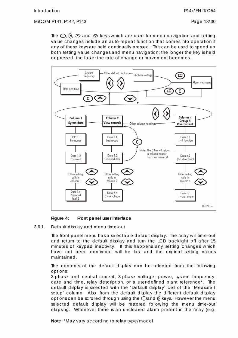
The , and keys which are used for menu navigation and setting value changes include an auto-repeat function that comes into operation if any of these keys are held continually pressed. This can be used to speed up both setting value changes and menu navigation; the longer the key is held depressed, the faster the rate of change or movement becomes.
�$�������;����$
�����������
9-�6��� � ��
< ���������
+�6������� ������ $�
��"#$��� %&'$�()&)
��"#$��*�+',�-'.�-(/
��"#$����-�#0�1
2'-.#--'�&
���5=5����
���8=5����������
����=5>?5���������
���5=83��%���
���8=8�����������
����=8>?5����������
���5=�3��%��� � � �8
���8=�(�@�<� � ��
����=�>?��6��� �
+�6����������� ����
�� ����5
+�6����������� ����
�� ����8
+�6����������� ����
�� �����
+�6����� ����6�����
����A��6��(�*�$�%� ������������� ����6�����������$��������
�
�
�
34542��
Figure 4: Front panel user interface
3.6.1 Default display and menu time-out
The front panel menu has a selectable default display. The relay will time-out and return to the default display and turn the LCD backlight off after 15 minutes of keypad inactivity. If this happens any setting changes which have not been confirmed will be lost and the original setting values maintained.
The contents of the default display can be selected from the following options: 3-phase and neutral current, 3-phase voltage, power, system frequency, date and time, relay description, or a user-defined plant reference*. The default display is selected with the ‘Default display’ cell of the ‘Measure’t setup’ column. Also, from the default display the different default display options can be scrolled through using the and keys. However the menu selected default display will be restored following the menu time-out elapsing. Whenever there is an uncleared alarm present in the relay (e.g.
Note: *May vary according to relay type/model
P14x/EN IT/C54 Introduction Page 14/30 MiCOM P141, P142, P143
Note: *May vary according to relay type/model
fault record, protection alarm, control alarm etc.) the default display will be replaced by:
Alarms/Faults Present
Entry to the menu structure of the relay is made from the default display and is not affected if the display is showing the ‘Alarms/Faults present’ message.
3.6.2 Menu navigation and setting browsing
The menu can be browsed using the four arrow keys, following the structure shown in Figure 4. Thus, starting at the default display the key will display the first column heading. To select the required column heading use the and keys. The setting data contained in the column can then be viewed by using the and keys. It is possible to return to the column header either by holding the [up arrow symbol] key down or by a single press of the clear key . It is only possible to move across columns at the column heading level. To return to the default display press the key or the clear key from any of the column headings. It is not possible to go straight to the default display from within one of the column cells using the auto-repeat facility of the key, as the auto-repeat will stop at the column heading. To move to the default display, the key must be released and pressed again.
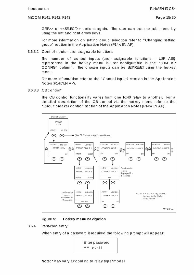
3.6.3 Hotkey menu navigation
The hotkey menu can be browsed using the two keys directly below the LCD. These are known as direct access keys. The direct access keys perform the function that is displayed directly above them on the LCD. Thus, to access the hotkey menu from the default display the direct access key below the “HOTKEY” text must be pressed. Once in the hotkey menu the and keys can be used to scroll between the available options and the direct access keys can be used to control the function currently displayed. If neither the or keys are pressed with 20 seconds of entering a hotkey sub menu, the relay will revert to the default display. The clear key C will also act to return to the default menu from any page of the hotkey menu. The layout of a typical page of the hotkey menu is described below.
The top line shows the contents of the previous and next cells for easy menu navigation.
The centre line shows the function.
The bottom line shows the options assigned to the direct access keys.
The functions available in the hotkey menu are listed below:
3.6.3.1 Setting group selection
The user can either scroll using <<NXT GRP>> through the available setting groups or <<SELECT>> the setting group that is currently displayed.
When the SELECT button is pressed a screen confirming the current setting group is displayed for 2 seconds before the user is prompted with the <<NXT
Introduction P14x/EN IT/C54 MiCOM P141, P142, P143 Page 15/30
GRP>> or <<SELECT>> options again. The user can exit the sub menu by using the left and right arrow keys.
For more information on setting group selection refer to “Changing setting group” section in the Application Notes (P14x/EN AP).
3.6.3.2 Control inputs – user assignable functions
The number of control inputs (user assignable functions – USR ASS) represented in the hotkey menu is user configurable in the “CTRL I/P CONFIG” column. The chosen inputs can be SET/RESET using the hotkey menu.
For more information refer to the “Control Inputs” section in the Application Notes (P14x/EN AP).
3.6.3.3 CB control*
The CB control functionality varies from one Px40 relay to another. For a detailed description of the CB control via the hotkey menu refer to the “Circuit breaker control” section of the Application Notes (P14x/EN AP).
)+��'�B�C���
�D��
C�(+C3504
)+�'�B (#�(���
E����<��D ��,�,�3?
������,�,�+�3�5
����(�
EC��� ����<��5?
�D��,�3
(+���+����3���5
+�
E��,�,�3 ����<��8?
�D��
(+���+����3���8
+�
E����<��5 ����<��D?
�D��
(+���+����3���8
+�
E����<��8 C���?
�D��
������,�,�+�3�8
����(�
EC��� ����<��5?
�D��,�3
������,�,�+�3�8
����(���
EC��� ����<��5?
(+���+����3���5
+�
EC��� ����<��8?
(+���+����3���5
�D��
EC��� ����<��8?
+!!
(����������������
���� $������8��������
(�������������������� $������8��������
.����(#�(����� ����<�� ������������/
���� ������ $
�+��A�EE�D��??�'�$���������6�����������6��)��*�$C����������
3580:��
Figure 5: Hotkey menu navigation
3.6.4 Password entry
When entry of a password is required the following prompt will appear:
Enter password **** Level 1
Note: *May vary according to relay type/model
P14x/EN IT/C54 Introduction Page 16/30 MiCOM P141, P142, P143
Note: *May vary according to relay type/model
Note: The password required to edit the setting is the prompt as shown above
A flashing cursor will indicate which character field of the password may be changed. Press the and keys to vary each character between A and Z. To move between the character fields of the password, use the and keys. The password is confirmed by pressing the enter key The display will revert to ‘Enter Password’ if an incorrect password is entered. At this point a message will be displayed indicating whether a correct password has been entered and if so what level of access has been unlocked. If this level is sufficient to edit the selected setting then the display will return to the setting page to allow the edit to continue. If the correct level of password has not been entered then the password prompt page will be returned to. To escape from this prompt press the clear key . Alternatively, the password can be entered using the ‘Password’ cell of the ‘System data’ column.
For the front panel user interface the password protected access will revert to the default access level after a keypad inactivity time-out of 15 minutes. It is possible to manually reset the password protection to the default level by moving to the ‘Password’ menu cell in the ‘System data’ column and pressing the clear key instead of entering a password.
3.6.5 Reading and clearing of alarm messages and fault records
The presence of one or more alarm messages will be indicated by the default display and by the yellow alarm LED flashing. The alarm messages can either be self-resetting or latched, in which case they must be cleared manually. To view the alarm messages press the read key. When all alarms have been viewed, but not cleared, the alarm LED will change from flashing to constant illumination and the latest fault record will be displayed (if there is one). To scroll through the pages of this use the key. When all pages of the fault record have been viewed, the following prompt will appear:
Press clear to reset alarms
To clear all alarm messages press ; to return to the alarms/faults present display and leave the alarms uncleared, press . Depending on the password configuration settings, it may be necessary to enter a password before the alarm messages can be cleared (see section on password entry). When the alarms have been cleared the yellow alarm LED will extinguish, as will the red trip LED if it was illuminated following a trip.
Alternatively it is possible to accelerate the procedure, once the alarm viewer has been entered using the key, the key can be pressed, this will move the display straight to the fault record. Pressing again will move straight to the alarm reset prompt where pressing once more will clear all alarms.
Introduction P14x/EN IT/C54 MiCOM P141, P142, P143 Page 17/30
Note: *May vary according to relay type/model
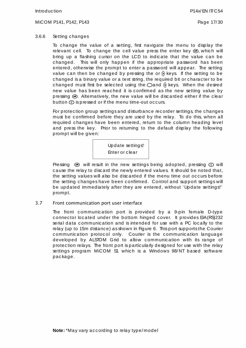
3.6.6 Setting changes
To change the value of a setting, first navigate the menu to display the relevant cell. To change the cell value press the enter key which will bring up a flashing cursor on the LCD to indicate that the value can be changed. This will only happen if the appropriate password has been entered, otherwise the prompt to enter a password will appear. The setting value can then be changed by pressing the or keys. If the setting to be changed is a binary value or a text string, the required bit or character to be changed must first be selected using theand keys. When the desired new value has been reached it is confirmed as the new setting value by pressing Alternatively, the new value will be discarded either if the clear button is pressed or if the menu time-out occurs.
For protection group settings and disturbance recorder settings, the changes must be confirmed before they are used by the relay. To do this, when all required changes have been entered, return to the column heading level and press the key. Prior to returning to the default display the following prompt will be given:
Update settings Enter or clear
Pressing will result in the new settings being adopted, pressing will cause the relay to discard the newly entered values. It should be noted that, the setting values will also be discarded if the menu time out occurs before the setting changes have been confirmed. Control and support settings will be updated immediately after they are entered, without ‘Update settings’ prompt.
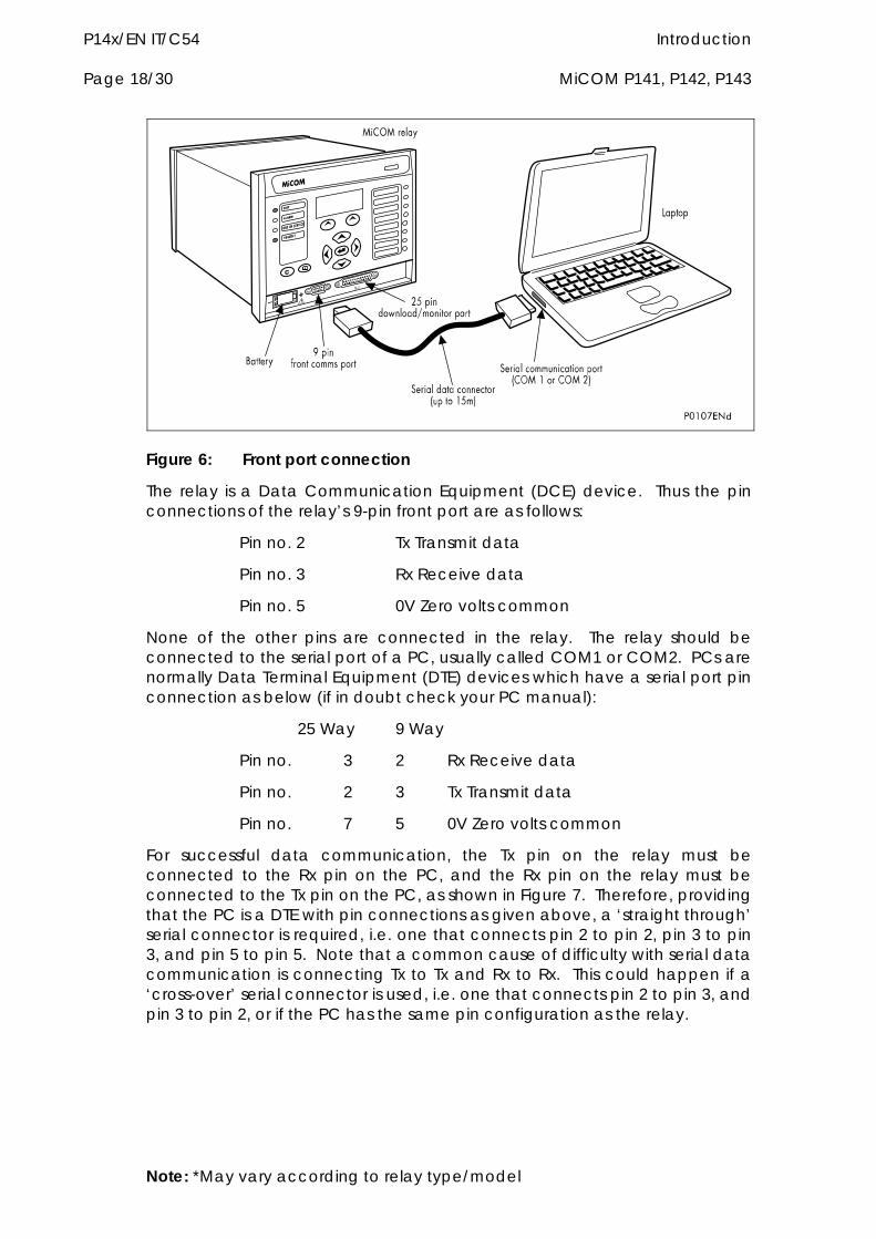
3.7 Front communication port user interface The front communication port is provided by a 9-pin female D-type connector located under the bottom hinged cover. It provides EIA(RS)232 serial data communication and is intended for use with a PC locally to the relay (up to 15m distance) as shown in Figure 6. This port supports the Courier communication protocol only. Courier is the communication language developed by ALSTOM Grid to allow communication with its range of protection relays. The front port is particularly designed for use with the relay settings program MiCOM S1 which is a Windows 98/NT based software package.
P14x/EN IT/C54 Introduction Page 18/30 MiCOM P141, P142, P143
d
Figure 6: Front port connection
The relay is a Data Communication Equipment (DCE) device. Thus the pin connections of the relay’s 9-pin front port are as follows:
Pin no. 2 Tx Transmit data
Pin no. 3 Rx Receive data
Pin no. 5 0V Zero volts common
None of the other pins are connected in the relay. The relay should be connected to the serial port of a PC, usually called COM1 or COM2. PCs are normally Data Terminal Equipment (DTE) devices which have a serial port pin connection as below (if in doubt check your PC manual):
25 Way 9 Way
Pin no. 3 2 Rx Receive data
Pin no. 2 3 Tx Transmit data
Pin no. 7 5 0V Zero volts common
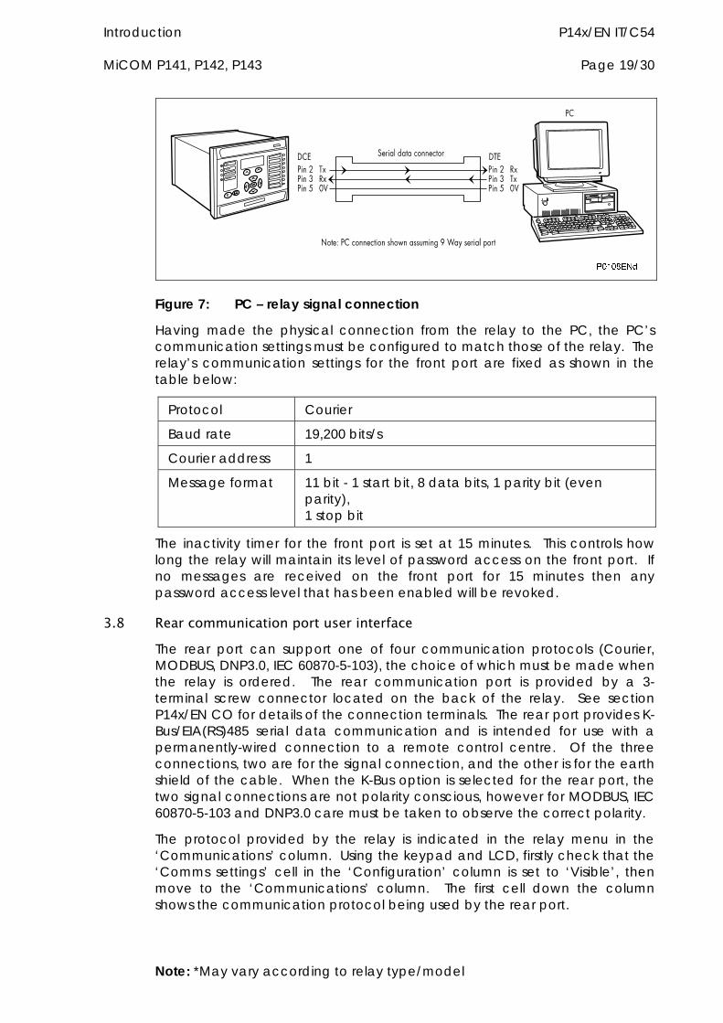
For successful data communication, the Tx pin on the relay must be connected to the Rx pin on the PC, and the Rx pin on the relay must be connected to the Tx pin on the PC, as shown in Figure 7. Therefore, providing that the PC is a DTE with pin connections as given above, a ‘straight through’ serial connector is required, i.e. one that connects pin 2 to pin 2, pin 3 to pin 3, and pin 5 to pin 5. Note that a common cause of difficulty with serial data communication is connecting Tx to Tx and Rx to Rx. This could happen if a ‘cross-over’ serial connector is used, i.e. one that connects pin 2 to pin 3, and pin 3 to pin 2, or if the PC has the same pin configuration as the relay.
Note: *May vary according to relay type/model
Introduction P14x/EN IT/C54 MiCOM P141, P142, P143 Page 19/30
Figure 7: PC – relay signal connection
Having made the physical connection from the relay to the PC, the PC’s communication settings must be configured to match those of the relay. The relay’s communication settings for the front port are fixed as shown in the table below:
Protocol Courier
Baud rate 19,200 bits/s
Courier address 1
Message format 11 bit - 1 start bit, 8 data bits, 1 parity bit (even parity), 1 stop bit
The inactivity timer for the front port is set at 15 minutes. This controls how long the relay will maintain its level of password access on the front port. If no messages are received on the front port for 15 minutes then any password access level that has been enabled will be revoked.
3.8 Rear communication port user interface The rear port can support one of four communication protocols (Courier, MODBUS, DNP3.0, IEC 60870-5-103), the choice of which must be made when the relay is ordered. The rear communication port is provided by a 3-terminal screw connector located on the back of the relay. See section P14x/EN CO for details of the connection terminals. The rear port provides K-Bus/EIA(RS)485 serial data communication and is intended for use with a permanently-wired connection to a remote control centre. Of the three connections, two are for the signal connection, and the other is for the earth shield of the cable. When the K-Bus option is selected for the rear port, the two signal connections are not polarity conscious, however for MODBUS, IEC 60870-5-103 and DNP3.0 care must be taken to observe the correct polarity.
The protocol provided by the relay is indicated in the relay menu in the ‘Communications’ column. Using the keypad and LCD, firstly check that the ‘Comms settings’ cell in the ‘Configuration’ column is set to ‘Visible’, then move to the ‘Communications’ column. The first cell down the column shows the communication protocol being used by the rear port.
Note: *May vary according to relay type/model
P14x/EN IT/C54 Introduction Page 20/30 MiCOM P141, P142, P143
Note: *May vary according to relay type/model
3.8.1 Courier communication
Courier is the communication language developed by ALSTOM Grid to allow remote interrogation of its range of protection relays. Courier works on a master/slave basis where the slave units contain information in the form of a database, and respond with information from the database when it is requested by a master unit.
The relay is a slave unit which is designed to be used with a Courier master unit such as MiCOM S1, MiCOM S10, PAS&T or a SCADA system. MiCOM S1 is a Windows NT4.0/98 compatible software package which is specifically designed for setting changes with the relay.
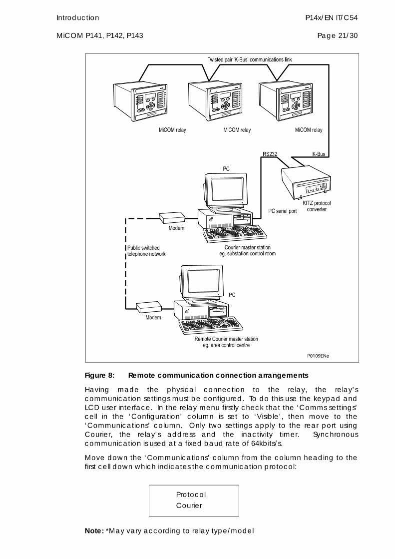
To use the rear port to communicate with a PC-based master station using Courier, a KITZ K-Bus to EIA(RS)232 protocol converter is required. This unit is available from ALSTOM Grid. A typical connection arrangement is shown in Figure 8. For more detailed information on other possible connection arrangements refer to the manual for the Courier master station software and the manual for the KITZ protocol converter. Each spur of the K-Bus twisted pair wiring can be up to 1000m in length and have up to 32 relays connected to it.
Introduction P14x/EN IT/C54 MiCOM P141, P142, P143 Page 21/30
P0109ENe
Figure 8: Remote communication connection arrangements
Having made the physical connection to the relay, the relay’s communication settings must be configured. To do this use the keypad and LCD user interface. In the relay menu firstly check that the ‘Comms settings’ cell in the ‘Configuration’ column is set to ‘Visible’, then move to the ‘Communications’ column. Only two settings apply to the rear port using Courier, the relay’s address and the inactivity timer. Synchronous communication is used at a fixed baud rate of 64kbits/s.
Move down the ‘Communications’ column from the column heading to the first cell down which indicates the communication protocol:
Protocol Courier
Note: *May vary according to relay type/model
P14x/EN IT/C54 Introduction Page 22/30 MiCOM P141, P142, P143
Note: *May vary according to relay type/model
The next cell down the column controls the address of the relay:
Remote address 1
Since up to 32 relays can be connected to one K-bus spur, as indicated in Figure 8, it is necessary for each relay to have a unique address so that messages from the master control station are accepted by one relay only. Courier uses an integer number between 0 and 254 for the relay address which is set with this cell. It is important that no two relays have the same Courier address. The Courier address is then used by the master station to communicate with the relay.
The next cell down controls the inactivity timer:
Inactivity timer 10.00 mins
The inactivity timer controls how long the relay will wait without receiving any messages on the rear port before it reverts to its default state, including revoking any password access that was enabled. For the rear port this can be set between 1 and 30 minutes.
Note that protection and disturbance recorder settings that are modified using an on-line editor such as PAS&T must be confirmed with a write to the ‘Save changes’ cell of the ‘Configuration’ column. Off-line editors such as MiCOM S1 do not require this action for the setting changes to take effect.
3.8.2 MODBUS communication
MODBUS is a master/slave communication protocol which can be used for network control. In a similar fashion to Courier, the system works by the master device initiating all actions and the slave devices, (the relays), responding to the master by supplying the requested data or by taking the requested action. MODBUS communication is achieved via a twisted pair connection to the rear port and can be used over a distance of 1000m with up to 32 slave devices.
To use the rear port with MODBUS communication, the relay’s communication settings must be configured. To do this use the keypad and LCD user interface. In the relay menu firstly check that the ‘Comms settings’ cell in the ‘Configuration’ column is set to ‘Visible’, then move to the ‘Communications’ column. Four settings apply to the rear port using MODBUS which are described below. Move down the ‘Communications’ column from the column heading to the first cell down which indicates the communication protocol:
Protocol MODBUS
Introduction P14x/EN IT/C54 MiCOM P141, P142, P143 Page 23/30
Note: *May vary according to relay type/model
The next cell down controls the MODBUS address of the relay:
MODBUS address 23
Up to 32 relays can be connected to one MODBUS spur, and therefore it is necessary for each relay to have a unique address so that messages from the master control station are accepted by one relay only. MODBUS uses an integer number between 1 and 247 for the relay address. It is important that no two relays have the same MODBUS address. The MODBUS address is then used by the master station to communicate with the relay.
The next cell down controls the inactivity timer:
Inactivity timer 10.00 mins
The inactivity timer controls how long the relay will wait without receiving any messages on the rear port before it reverts to its default state, including revoking any password access that was enabled. For the rear port this can be set between 1 and 30 minutes.
The next cell down the column controls the baud rate to be used:
Baud rate 9600 bits/s
MODBUS communication is asynchronous. Three baud rates are supported by the relay, ‘9600 bits/s’, ‘19200 bits/s’ and ‘38400 bits/s’. It is important that whatever baud rate is selected on the relay is the same as that set on the MODBUS master station.
The next cell down controls the parity format used in the data frames:
Parity None
The parity can be set to be one of ‘None’, ‘Odd’ or ‘Even’. It is important that whatever parity format is selected on the relay is the same as that set on the MODBUS master station.
The next cell down controls the IEC time format used in the data frames (available in software version 0300J only):
MODBUS IEC Time Standard
The MODBUS IEC time can be set to ‘Standard’ or ‘Reverse’. For a complete definition see Look and Feel Database ‘P14x/EN GC/B54’, datatype G12.
P14x/EN IT/C54 Introduction Page 24/30 MiCOM P141, P142, P143
Note: *May vary according to relay type/model
3.8.3 IEC 60870-5 CS 103 communication
The IEC specification IEC 60870-5-103: Telecontrol Equipment and Systems, Part 5: Transmission Protocols Section 103 defines the use of standards IEC 60870-5-1 to IEC 60870-5-5 to perform communication with protection equipment. The standard configuration for the IEC 60870-5-103 protocol is to use a twisted pair connection over distances up to 1000m. As an option for IEC 60870-5-103, the rear port can be specified to use a fibre optic connection for direct connection to a master station. The relay operates as a slave in the system, responding to commands from a master station. The method of communication uses standardised messages which are based on the VDEW communication protocol.
To use the rear port with IEC 60870-5-103 communication, the relay’s communication settings must be configured. To do this use the keypad and LCD user interface. In the relay menu firstly check that the ‘Comms settings’ cell in the ‘Configuration’ column is set to ‘Visible’, then move to the ‘Communications’ column. Four settings apply to the rear port using IEC 60870-5-103 which are described below. Move down the ‘Communications’ column from the column heading to the first cell which indicates the communication protocol:
Protocol IEC 60870-5-103
The next cell down controls the IEC 60870-5-103 address of the relay:
Remote address 162
Up to 32 relays can be connected to one IEC 60870-5-103 spur, and therefore it is necessary for each relay to have a unique address so that messages from the master control station are accepted by one relay only. IEC 60870-5-103 uses an integer number between 0 and 254 for the relay address. It is important that no two relays have the same IEC 60870-5-103 address. The IEC 60870-5-103 address is then used by the master station to communicate with the relay.
The next cell down the column controls the baud rate to be used:
Baud rate 9600 bits/s
IEC 60870-5-103 communication is asynchronous. Two baud rates are supported by the relay, ‘9600 bits/s’ and ‘19200 bits/s’. It is important that whatever baud rate is selected on the relay is the same as that set on the IEC 60870-5-103 master station.
The next cell down controls the period between IEC 60870-5-103 measurements:
Introduction P14x/EN IT/C54 MiCOM P141, P142, P143 Page 25/30
Note: *May vary according to relay type/model
Measure’t period 30.00 s
The IEC 60870-5-103 protocol allows the relay to supply measurements at regular intervals. The interval between measurements is controlled by this cell, and can be set between 1 and 60 seconds.
The following cell is not currently used but is available for future expansion
Inactive timer
The next cell down the column controls the physical media used for the communication:
Physical link EIA(RS)485
The default setting is to select the electrical EIA(RS)485 connection. If the optional fibre optic connectors are fitted to the relay, then this setting can be changed to ‘Fibre optic’. This cell is also invisible if second rear comms port is fitted as it is mutually exclusive with the fibre optic connectors.
The next cell down can be used for monitor or command blocking:
CS103 Blocking
There are three settings associated with this cell; these are:
Disabled - No blocking selected.
Monitor Blocking - When the monitor blocking DDB Signal is active high, either by energising an opto input or control input, reading of the status information and disturbance records is not permitted. When in this mode the relay returns a “Termination of general interrogation” message to the master station.
Command Blocking - When the command blocking DDB signal is active high, either by energising an opto input or control input, all remote commands will be ignored (i.e. CB Trip/Close, change setting group etc.). When in this mode the relay returns a “negative acknowledgement of command” message to the master station.
3.8.4 DNP 3.0 Communication
The DNP 3.0 protocol is defined and administered by the DNP User Group. Information about the user group, DNP 3.0 in general and protocol specifications can be found on their website: www.dnp.org
P14x/EN IT/C54 Introduction Page 26/30 MiCOM P141, P142, P143
Note: *May vary according to relay type/model
The relay operates as a DNP 3.0 slave and supports subset level 2 of the protocol plus some of the features from level 3. DNP 3.0 communication is achieved via a twisted pair connection to the rear port and can be used over a distance of 1000m with up to 32 slave devices.
To use the rear port with DNP 3.0 communication, the relay’s communication settings must be configured. To do this use the keypad and LCD user interface. In the relay menu firstly check that the ‘Comms setting’ cell in the ‘Configuration’ column is set to ‘Visible’, then move to the ‘Communications’ column. Four settings apply to the rear port using DNP 3.0, which are described below. Move down the ‘Communications’ column from the column heading to the first cell which indicates the communications protocol:
Protocol DNP 3.0
The next cell controls the DNP 3.0 address of the relay:
DNP 3.0 address 232
Upto 32 relays can be connected to one DNP 3.0 spur, and therefore it is necessary for each relay to have a unique address so that messages from the master control station are accepted by only one relay. DNP 3.0 uses a decimal number between 1 and 65519 for the relay address. It is important that no two relays have the same DNP 3.0 address. The DNP 3.0 address is then used by the master station to communicate with the relay.
The next cell down the column controls the baud rate to be used:
Baud rate 9600 bits/s
DNP 3.0 communication is asynchronous. Six baud rates are supported by the relay ‘1200bits/s’, ‘2400bits/s’, ‘4800bits/s’, ’9600bits/s’, ‘19200bits/s’ and ‘38400bits/s’. It is important that whatever baud rate is selected on the relay is the same as that set on the DNP 3.0 master station.
The next cell down the column controls the parity format used in the data frames:
Parity None
The parity can be set to be one of ‘None’, ‘Odd’ or ‘Even’. It is important that whatever parity format is selected on the relay is the same as that set on the DNP 3.0 master station.
Introduction P14x/EN IT/C54 MiCOM P141, P142, P143 Page 27/30
Note: *May vary according to relay type/model
The next cell down the column sets the time synchronisation request from the master by the relay:
Time Synch Enabled
The time synch can be set to either enabled or disabled. If enabled it allows the DNP 3.0 master to synchronise the time.
3.9 Second rear communication port For relays with Courier, MODBUS, IEC60870-5-103 or DNP3 protocol on the first rear communications port there is the hardware option of a second rear communications port, which will run the Courier language. This can be used over one of three physical links: twisted pair K-Bus (non polarity sensitive), twisted pair EIA(RS)485 (connection polarity sensitive) or EIA(RS)232.
The settings for this port are located immediately below the ones for the first port as described in previous sections of P14x/EN IT. Move down the settings until the following sub heading is displayed.
REAR PORT2 (RP2)
The next cell down indicates the language, which is fixed at Courier for RP2.
RP2 Protocol Courier
The next cell down indicates the status of the hardware, e.g.
RP2 Card Status EIA(RS)232 OK
The next cell allows for selection of the port configuration.
RP2 Port Config EIA(RS)232
The port can be configured for EIA(RS)232, EIA(RS)485 or K-Bus.
In the case of EIA(RS)232 and EIA(RS)485 the next cell selects the communication mode.
RP2 Comms Mode IEC60870 FT1.2
The choice is either IEC60870 FT1.2 for normal operation with 11-bit modems, or 10-bit no parity.
The next cell down controls the comms port address.
P14x/EN IT/C54 Introduction Page 28/30 MiCOM P141, P142, P143
RP2 Address 255
Since up to 32 relays can be connected to one K-bus spur, as indicated in Figure 8, it is necessary for each relay to have a unique address so that messages from the master control station are accepted by one relay only. Courier uses an integer number between 0 and 254 for the relay address which is set with this cell. It is important that no two relays have the same Courier address. The Courier address is then used by the master station to communicate with the relay.
The next cell down controls the inactivity timer.
RP2 Inactivity Timer 15 mins
The inactivity timer controls how long the relay will wait without receiving any messages on the rear port before it reverts to its default state, including revoking any password access that was enabled. For the rear port this can be set between 1 and 30 minutes.
In the case of EIA(RS)232 and EIA(RS)485 the next cell down controls the baud rate. For K-Bus the baud rate is fixed at 64kbit/second between the relay and the KITZ interface at the end of the relay spur.
RP2 Baud Rate 19200
Courier communications is asynchronous. Three baud rates are supported by the relay, ‘9600 bits/s’, ‘19200 bits/s’ and ‘38400 bits/s’.
38410��<
���������������� ���������������������������������
� !"���#��$%���&�'����(�������)���������'��*����
&�' ���������
��� ���������
� !"&��
)�'�) )�'�)
+ �����&�&+ �����&�&
+ �����&�&(����
+ �����&�&(����
������� ������&
������� �$%��(����
�,
-+
���
.�
�/0
�+
1!
��
/��
�,
�+
��
,�
�2!2.2
!�������
�$%��
1������������ ��3'�4����5� 6�����(��� �3#�&�' ������37�5������
� !"��&
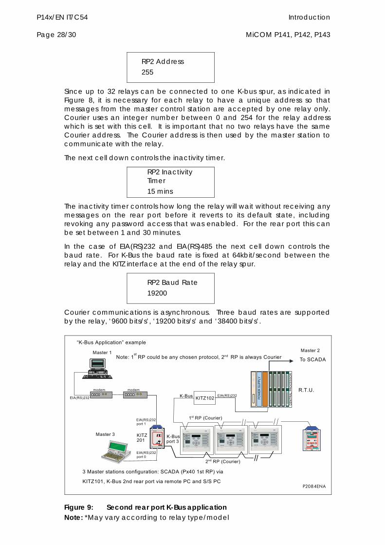
8�$%����((3 ����9����)(3�
Note: *May vary according to relay type/model Figure 9: Second rear port K-Bus application
Introduction P14x/EN IT/C54 MiCOM P141, P142, P143 Page 29/30
P2085ENc
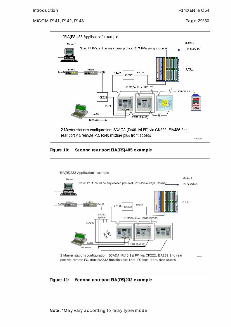
Figure 10: Second rear port EIA(RS)485 example
P2086ENA2 Master stations configuration: SCADA (Px40 1st RP) via CK222, EIA232 2nd rearport via remote PC, max EIA232 bus distance 15m, PC local front/ rear access
2nd RP (EIA232)
modem modemEIA232 EIA232
EIA232
Master 1 Master 2
EIA232
POW
ER S
UPP
LY
CEN
TRA
L PR
OC
ESSO
R
R.T.U.
To SCADA
EIA232splitter
Front port
MiCOMS1
EIA232
Note: 1st RP could be any chosen protocol, 2nd RP is always Courier
CK222
15mmax
1st RP (Modbus / DNP/ IEC103)
EIA485
“EIA(RS)232 Application” example
Figure 11: Second rear port EIA(RS)232 example
Note: *May vary according to relay type/model
P14x/EN IT/C54 Introduction Page 30/30 MiCOM P141, P142, P143
Note: *May vary according to relay type/model

Application Notes P14x/EN AP/C54 MiCOM P141, P142, P143
APPLICATION NOTES

P14x/EN AP/C54 Application Notes MiCOM P141, P142, P143
Application Notes P14x/EN AP/C54 MiCOM P141, P142, P143 Page 3/190
CONTENT
1. INTRODUCTION 13
1.1 Protection of feeders 13
1.2 MiCOM feeder relay 14
1.2.1 Protection features 14
1.2.2 Non-protection features 15
2. APPLICATION OF INDIVIDUAL PROTECTION FUNCTIONS 17
2.1 Configuration column 17
2.2 Overcurrent protection 18
2.2.1 RI curve 22
2.2.2 Transformer magnetising inrush 22
2.2.3 Application of timer hold facility 23
2.2.4 Setting guidelines 23
2.3 Directional overcurrent protection 26
2.3.1 Parallel feeders 27
2.3.2 Ring main arrangements 28
2.3.3 Synchronous polarisation 30
2.3.4 Setting guidelines 30
2.4 Thermal overload protection 31
2.4.1 Single time constant characteristic 32
2.4.2 Dual time constant characteristic 32
2.5 Setting guidelines 35
2.5.1 Single time constant characteristic 35
2.5.2 Dual time constant characteristic 36
2.6 Earth fault protection 36
2.6.1 Standard earth fault protection elements 36
2.6.1.1 IDG curve 39
2.6.2 Sensitive earth fault protection element (SEF) 40
2.7 Directional earth fault protection (DEF) 43
2.7.1 Residual voltage polarisation 44
2.7.2 Negative sequence polarisation 44
2.7.3 General setting guidelines for DEF 45
2.7.4 Application to insulated systems 45
P14x/EN AP/C54 Application Notes Page 4/190 MiCOM P141, P142, P143
2.7.5 Setting guidelines - insulated systems 48
2.7.6 Application to Petersen Coil earthed systems 48
2.8 Operation of sensitive earth fault element 54
2.9 Application considerations 56
2.9.1 Calculation of required relay settings 56
2.9.2 Application of settings to the relay 57
2.10 Restricted earth fault protection 57
2.10.1 Biased differential protection 58
2.10.2 Setting guidelines for biased REF protection 61
2.10.3 High impedance restricted earth fault protection 61
2.10.4 Setting guidelines for high impedance REF 63
2.10.5 Use of METROSIL non-linear resistors 64
2.11 Residual overvoltage (neutral displacement) protection 67
2.11.1 Setting guidelines 71
2.12 Undervoltage protection 71
2.12.1 Setting guidelines 73
2.13 Overvoltage protection 73
2.13.1 Setting guidelines 75
2.14 Negative sequence overvoltage protection 75
2.14.1 Setting guidelines 76
2.15 Negative sequence overcurrent protection (NPS) 76
2.15.1 Setting guidelines 77
2.15.2 Negative phase sequence current threshold, '2> Current Set' 79
2.15.3 Time delay for the negative phase sequence overcurrent element, ‘2> Time Delay’ 80
2.15.4 Directionalising the negative phase sequence overcurrent element 80
2.16 Voltage controlled overcurrent protection (51V) 81
2.16.1 Setting guidelines 82
2.17 Circuit breaker fail protection (CBF) 82
2.18 Breaker failure protection configurations 83
2.18.1 Reset mechanisms for breaker fail timers 84
2.19 Typical settings 86
2.19.1 Breaker fail timer settings 86
2.19.2 Breaker fail undercurrent settings 87
2.20 Broken conductor detection 87
Application Notes P14x/EN AP/C54 MiCOM P141, P142, P143 Page 5/190
2.20.1 Setting guidelines 88
2.21 Frequency protection 90
2.22 Independent rate of change of frequency protection [87R] [software versions 0210G and 0300J] 91
2.22.1 Overview 91
2.22.2 Basic functionality 92
2.23 Cold-load pick-up logic 94
2.23.1 Air conditioning/resistive heating loads 96
2.23.2 Motor feeders 96
2.23.3 Earth fault protection applied to transformers 97
2.23.4 Switch onto fault protection (SOTF) 97
2.24 Selective overcurrent logic 97
2.25 Neutral admittance protection 98
2.25.1 Operation of admittance protection 100
2.25.2 Operation of conductance protection 100
2.25.3 Operation of susceptance protection 101
3. OTHER PROTECTION CONSIDERATIONS 102
3.1 Blocked overcurrent protection 102
4. APPLICATION OF NON PROTECTION FUNCTIONS 104
4.1 Three phase auto-reclosing 104
4.1.1 Logic functions 108
4.1.1.1 Logic inputs 108
4.1.1.1.1 CB healthy 109
4.1.1.1.2 BAR 109
4.1.1.1.3 Reset lockout 109
4.1.1.1.4 Auto mode 109
4.1.1.1.5 Live line mode 109
4.1.1.1.6 Telecontrol mode 109
4.1.1.1.7 Live/Dead Ccts OK 109
4.1.1.1.8 AR SysChecks OK 110
4.1.1.1.9 Ext AR Prot trip/start 110
4.1.1.1.10 DAR complete 110
4.1.1.1.11 CB in service 110
4.1.1.1.12 AR restart 110
4.1.1.1.13 DT OK to start 111
P14x/EN AP/C54 Application Notes Page 6/190 MiCOM P141, P142, P143
4.1.1.1.14 Dead time enabled 111
4.1.1.1.15 AR Init trip test 111
4.1.1.2 Autoreclose logic outputs 111
4.1.1.2.1 AR in progress 111
4.1.1.2.2 Sequence counter status 111
4.1.1.2.3 Successful close 112
4.1.1.2.4 AR in service 112
4.1.1.2.5 Block main prot 112
4.1.1.2.6 Block SEF prot 112
4.1.1.2.7 Reclose checks 112
4.1.1.2.8 Dead T in prog 112
4.1.1.2.9 DT complete 112
4.1.1.2.10 System checks indication 113
4.1.1.2.11 Auto close 113
4.1.1.2.12 “Trip when AR blocked” indication 113
4.1.1.2.13 Reset lockout indication 113
4.1.1.3 Autoreclose alarms 113
4.1.1.3.1 AR no checksync (latched) 113
4.1.1.3.2 AR CB unhealthy (latched) 113
4.1.1.3.3 AR lockout (self reset) 113
4.1.2 Autoreclose logic operating sequence 114
4.1.3 Main operating features 114
4.1.3.1 Operation modes 114
4.1.3.2 Autoreclose initiation 117
4.1.3.3 Blocking instantaneous protection during an AR cycle 118
4.1.3.4 Dead time control 119
4.1.3.5 System checks 120
4.1.3.6 Reclaim timer initiation 120
4.1.3.7 Autoreclose inhibit following manual close 121
4.1.3.8 AR lockout 121
4.1.3.8.1 Reset from lockout 121
4.1.3.9 Sequence co-ordination 122
4.1.3.10 Check synchronising for first reclose 123
4.1.4 Setting guidelines 123
4.1.4.1 Number of shots 123
4.1.4.2 Dead timer setting 123
4.1.4.2.1 Stability and synchronism requirements 124
Application Notes P14x/EN AP/C54 MiCOM P141, P142, P143 Page 7/190
4.1.4.2.2 Operational convenience 124
4.1.4.2.3 Load requirements 124
4.1.4.2.4 Circuit breaker 125
4.1.4.2.5 Fault de-ionising time 125
4.1.4.2.6 Protection reset 126
4.1.4.3 Reclaim timer setting 126
4.2 Auto reset of trip LED indication 127
4.3 Check synchronism (applicable to P143) 127
4.3.1 Overview 127
4.3.2 VT selection 128
4.3.3 Basic functionality 129
4.3.4 Check sync 2 and system split 132
4.3.4.1 Check sync 2 freq+comp setting 132
4.3.5 Synchronism check 133
4.3.6 Slip control by timer 133
4.3.7 System split 134
4.4 Voltage transformer supervision (VTS) 137
4.4.1 Loss of all three phase voltages under load conditions 137
4.4.2 Absence of three phase voltages upon line energisation 138
4.4.2.1 Inputs 139
4.4.2.2 Outputs 140
4.4.3 Menu settings 141
4.5 Current transformer supervision 142
4.5.1 The CT supervision feature 142
4.5.2 Setting the CT supervision element 143
4.6 Circuit breaker state monitoring 143
4.6.1 Circuit breaker state monitoring features 143
4.7 Pole dead logic 145
4.8 Circuit breaker condition monitoring 146
4.8.1 Circuit breaker condition monitoring features 147
4.9 Setting guidelines 148
4.9.1 Setting the ^ thresholds 148
4.9.2 Setting the number of operations thresholds 149
4.9.3 Setting the operating time thresholds 149
4.9.4 Setting the excessive fault frequency thresholds 149
4.10 Circuit breaker control 149
P14x/EN AP/C54 Application Notes Page 8/190 MiCOM P141, P142, P143
4.15 Measurements 169
4.10.1 CB control using “hotkeys” 152
4.11 Trip circuit supervision (TCS) 153
4.11.1 TCS scheme 1 153
4.11.1.1 Scheme description 153
4.11.2 Scheme 1 PSL 154
4.11.3 TCS scheme 2 155
4.11.3.1 Scheme description 155
4.11.4 Scheme 2 PSL 156
4.11.5 TCS scheme 3 156
4.11.5.1 Scheme description 156
4.11.6 Scheme 3 PSL 157
4.12 Fault locator 157
4.12.1 Introduction 157
4.12.2 Basic theory for ground faults 157
4.12.3 Data acquisition and buffer processing 158
4.12.4 Faulted phase selection 158
4.12.5 The fault location calculation 158
4.12.5.1 Obtaining the vectors 158
4.12.5.2 Solving the equation for the fault location 159
4.12.6 Fault locator settings 160
4.12.7 Fault locator trigger 160
4.12.8 Setting example 160
4.13 Event & fault records 161
4.13.1 Types of event 162
4.13.1.1 Change of state of opto-isolated inputs 163
4.13.1.2 Change of state of one or more output relay contacts 163
4.13.1.3 Relay alarm conditions 163
4.13.1.4 Protection element starts and trips 164
4.13.1.5 General events 164
4.13.1.6 Fault records 164
4.13.1.7 Maintenance reports 165
4.13.1.8 Setting changes 165
4.13.2 Resetting of event/fault records 165
4.13.3 Viewing event records via MiCOM S1 support software 166
4.13.4 Event filtering 167
4.14 Disturbance recorder 167
Application Notes P14x/EN AP/C54 MiCOM P141, P142, P143 Page 9/190
4.15.1 Measured voltages and currents 169
4.15.2 Sequence voltages and currents 170
4.15.3 Slip frequency 170
4.15.4 Power and energy quantities 170
4.15.5 Rms. voltages and currents 170
4.15.6 Demand values 171
4.15.7 Settings 171
4.16 Changing setting groups 172
4.17 Control inputs 173
4.18 VT Connections 174
4.18.1 Open delta (vee connected) VT's 174
4.18.2 VT single point earthing 175
4.19 Real time clock synchronization via opto-inputs 175
5. PROGRAMMABLE SCHEME LOGIC DEFAULT SETTINGS 177
5.1 Logic input mapping 177
5.2 Relay output contact mapping 178
5.3 Relay output conditioning 180
5.4 Programmable LED output mapping 181
5.5 Fault recorder start mapping 181
5.6 PSL DATA column 182
6. CT/VT REQUIREMENTS 183
6.1 Non-directional definite time/IDMT overcurrent & earth fault protection183
6.1.1 Time-delayed phase overcurrent elements 183
6.1.2 Time-delayed earth fault overcurrent elements 183
6.2 Non-directional instantaneous overcurrent & earth fault protection 183
6.2.1 CT requirements for instantaneous phase overcurrent elements 183
6.2.2 CT requirements for instantaneous earth fault overcurrent elements 183
6.3 Directional definite time/IDMT overcurrent & earth fault protection 183
6.3.1 Time-delayed phase overcurrent elements 183
6.3.2 Time-delayed earth fault overcurrent elements 183
6.4 Directional instantaneous overcurrent & earth fault protection 183
6.4.1 CT requirements for instantaneous phase overcurrent elements 183
6.4.2 CT requirements for instantaneous earth fault overcurrent elements 184
P14x/EN AP/C54 Application Notes Page 10/190 MiCOM P141, P142, P143
6.5 Non-directional/directional definite time/IDMT sensitive earth fault (SEF) protection 184
6.5.1 Non-directional time delayed SEF protection (residually connected) 184
6.5.2 Non-directional instantaneous SEF protection (residually connected) 184
6.5.3 Directional time delayed SEF protection (residually connected) 184
6.5.4 Directional instantaneous SEF protection (residually connected) 184
6.5.5 SEF protection - as fed from a core-balance CT 184
6.6 Low impedance restricted earth fault protection 185
6.7 High impedance restricted earth fault protection 185
7. COMMISSIONING TEST MENU 186
7.1 Opto I/P status 187
7.2 Relay O/P status 187
7.3 Test port status 187
7.4 LED status 187
7.5 Monitor bits 1 to 8 187
7.6 Test mode 188
7.7 Test pattern 188
7.8 Contact test 188
7.9 Test LEDs 189
7.10 Test autoreclose 189
7.11 Using a monitor/download port test box 189
Figure 1: Protection for silicon rectifiers 24
Figure 2: Matching curve to load and thermal limit of rectifier 25
Figure 3: Typical distribution system using parallel transformers 27
Figure 4: Typical ring main with associated overcurrent protection 29
Figure 5: Spreadsheet calculation for dual time constant thermal characteristic 34
Figure 6: Dual time constant thermal characteristic 34
Figure 7: Three phase overcurrent & residually connected earth fault protection 39
Figure 8: IDG characteristic 40
Application Notes P14x/EN AP/C54 MiCOM P141, P142, P143 Page 11/190
Figure 9: Positioning of core balance current transformers 43
Figure 10: Current distribution in an insulated system with C phase fault 46
Figure 11: Phasor diagrams for insulated system with C phase fault 47
Figure 12: Current distribution in Petersen Coil earthed system 49
Figure 13: Distribution of currents during a C phase to earth fault 50
Figure 14: Theoretical case - no resistance present in XL or XC 51
Figure 15: Zero sequence network showing residual currents 52
Figure 16: Practical case - resistance present in XL and Xc 53
Figure 17: Resistive components of spill current 55
Figure 18a: Relay connections for biased REF protection 59
Figure 18b: REF bias characteristic 59
Figure 18c: REF bias characteristic 60
Figure 19: High impedance principle 62
Figure 20: High impedance REF relay/CT connections 63
Figure 21a: Residual voltage, solidly earthed system 68
Figure 21b: Residual voltage, resistance earthed system 69
Figure 22: Negative sequence O/C non-directional operation 79
Figure 23: Negative sequence O/C directional operation 79
Figure 24: CB fail logic 83
Figure 25: Sequence network connection diagram 88
Figure 26: Rate of change of frequency protection 92
Figure 27a: Simple busbar blocking scheme (single incomer) 102
Figure 27b: Simple busbar blocking scheme (single incomer) 103
Figure 28: Operating modes 116
Figure 29: Mode select functional diagram 117
Figure 30: Trip LED logic diagram 127
Figure 31: Synchro check and synchro split functionality 135
Figure 32: System checks functional logic diagram 136
Figure 33: Check synch default PSL 137
Figure 34: VTS Logic 139
Figure 35: CT Supervision function block diagram 142
Figure 36: CB state monitoring 145
Figure 37: Pole dead logic 146
Figure 38: Remote control of circuit breaker 150

P14x/EN AP/C54 Application Notes Page 12/190 MiCOM P141, P142, P143
Figure 39: CB control hotkey menu 153
Figure 40: TCS scheme 1 153
Figure 41: PSL for TCS schemes 1 and 3 155
Figure 42: TCS scheme 2 155
Figure 43: PSL for TCS scheme 2 156
Figure 44: TCS scheme 3 156
Figure 45: Two machine equivalent circuit 157
Figure 46: Fault locator selection of fault current zero 159

Application Notes P14x/EN AP/C54 MiCOM P141, P142, P143 Page 13/190
1. INTRODUCTION
1.1 Protection of feeders The secure and reliable transmission and distribution of power within a network is heavily dependent upon the integrity of the overhead lines and underground cables which link the various sections of the network together. As such, the associated protection system must also provide both secure and reliable operation.
The most common fault conditions, on both overhead lines and cables, are short circuit faults. Such faults may occur between phases but will most often involve one or more phases becoming short circuit to earth. Faults of this nature require the fastest possible fault clearance times but at the same time allowing suitable co-ordination with other downstream protection devices.
Fault sensitivity is an issue common to all voltage levels. For transmission systems, tower footing resistance can be high. Also, high resistance faults might be prevalent where lines pass over sandy or rocky terrain. Fast, discriminative fault clearance may still be required for these fault conditions.
The effect of fault resistance is more pronounced on lower voltage systems, resulting in potentially lower fault currents, which in turn increases the difficulty in the detection of high resistance faults. In addition, many distribution systems use earthing arrangements designed to limit the passage of earth fault current. Methods such as resistance earthing, Petersen Coil earthing or insulated systems make the detection of earth faults difficult. Special protection requirements are often used to overcome these problems.
For distribution systems, continuity of supply is of paramount importance. The majority of faults on overhead lines are transient or semi-permanent in nature. Multi-shot autoreclose cycles are therefore commonly used in conjunction with instantaneous tripping elements to increase system availability. For permanent faults it is essential that only the faulted section of plant is isolated. As such, high speed, discriminative fault clearance is often a fundamental requirement of any protection scheme on a distribution network.
Power transformers are encountered at all system voltage levels and will have their own specific requirements with regard to protection. In order to limit the damage incurred by a transformer under fault conditions, fast clearance of winding phase to phase and phase to earth faults is a primary requirement.
Damage to items of plant such as transformers, cables and lines may also be incurred by excessive loading conditions, which leads directly to overheating of the equipment and subsequent degradation of the insulation. To protect against conditions of this nature, protective devices require characteristics which closely match the thermal withstand capability of the item of plant in question.
Uncleared faults, arising from either failure of the associated protection system or of the switchgear itself, must also be given due consideration. As such, the protection devices concerned may well be fitted with logic to deal with breaker failure conditions, in addition to the relays located upstream being required to provide adequate back-up protection for the condition.

P14x/EN AP/C54 Application Notes Page 14/190 MiCOM P141, P142, P143
Other situations may arise on overhead lines, such as broken phase conductors. Being a series fault condition, it has traditionally been very difficult to detect. However, with numerical technology, it is now possible to design elements which are responsive to such unbalanced system conditions and to subsequently issue alarm/trip signals.
On large networks, time co-ordination of the overcurrent and earth fault relays can often lead to problematic grading situations or, as is often the case, excessive fault clearance times. Such problems can be overcome by relays operating in blocked overcurrent schemes.
1.2 MiCOM feeder relay MICOM relays are a new range of products from ALSTOM Grid. Using the latest numerical technology the range includes devices designed for application to a wide range of power system plant such as motors, generators, feeders, overhead lines and cables.
Each relay is designed around a common hardware and software platform in order to achieve a high degree of commonality between products. One such product in the range is the Feeder Relay. The relay has been designed to cater for the protection of a wide range of overhead lines and underground cables from distribution to transmission voltage levels.
The relay also includes a comprehensive range of non-protection features to aid with power system diagnosis and fault analysis. All these features can be accessed remotely from one of the relays remote serial communications options.
1.2.1 Protection features
The P140 feeder relays contain a wide variety of protection functions. There are 3 separate models available – P141, P142 and P143, to cover a wide range of applications. The protection features of each model are summarised below:
Three phase overcurrent protection – Four overcurrent measuring stages are provided for each phase and each stage is selectable to be either non-directional, directional forward or directional reverse. Stages 1 and 2 may be set Inverse Definite Minimum Time (IDMT) or Definite Time (DT); stages 3 and 4 may be set DT only.
Earth fault protection – Three independent earth fault elements are provided; derived, measured and sensitive earth fault protection. Each element is equipped with four stages which are independently selectable to be either non-directional, directional forward or directional reverse. Sensitive Earth Fault can be configured as a cos or Vcos (Wattmetric) element for application to Petersen Coil Earthed systems, or as a Restricted Earth Fault (REF) element.
Voltage controlled overcurrent protection – Provides backup protection for remote phase to phase faults by increasing the sensitivity of stages 1 and 2 of the overcurrent protection.
Negative sequence overcurrent protection – This can be selected to be either non-directional, directional forward or directional reverse and provides remote backup protection for both phase to earth and phase to phase faults.
Application Notes P14x/EN AP/C54 MiCOM P141, P142, P143 Page 15/190
Undervoltage protection – Two stage, configurable as either phase to phase or phase to neutral measuring. Stage 1 may be selected as either IDMT or DT and stage 2 is DT only.
Overvoltage protection – Two stage, configurable as either phase to phase or phase to neutral measuring. Stage 1 may be selected as either IDMT or DT and stage 2 is DT only.
Negative sequence overvoltage protection – Definite time delayed element to provide either a tripping or interlocking function upon detection of unbalanced supply voltages.
Neutral admittance protection – operates from either the SEF CT or EF CT to provide single stage admittance, conductance and susceptance elements.
Residual overvoltage (neutral voltage displacement) protection – Provides an additional method of earth fault detection and has two stages; stage 1 may be selected as either IDMT or DT and stage 2 is DT only.
Thermal overload protection – Provides thermal characteristics which are suitable for both cables and transformers. Alarm and trip stages are provided.
Frequency protection – Provides 4 stage underfrequency and 2 stage overfrequency protection.
Broken conductor detection – To detect open circuit faults.
Circuit breaker fail protection – Two stage breaker fail protection.
Autoreclose facility – Integral three phase multi-shot autoreclose with external initiation. (P142/143 only)
Autoreclose with check synchronisation – Integral three phase multi-shot autoreclose with external initiation and check synchronisation. Includes selectable operating modes such as Auto, Non-Auto, Live-line etc., in addition to Sequence Co-ordination Logic. (P143 only)
Cold load pick-up logic – May be used to transiently raise the settings, for both phase and earth fault protection, following closure of the circuit breaker.
Selective overcurrent logic – Provides the capability of temporarily altering the time settings of stages 3 and 4 of the phase overcurrent, earth fault and sensitive earth fault elements.
Voltage transformer supervision – To prevent mal-operation of voltage dependent protection elements upon loss of a VT input signal.
Current transformer supervision – To prevent mal-operation of current dependent protection elements upon loss of a CT input signal.
Programmable scheme logic – Allows user defined protection and control logic to suit particular customer applications.

P14x/EN AP/C54 Application Notes Page 16/190 MiCOM P141, P142, P143
1.2.2 Non-protection features
Below is a summary of the P140 relays' non-protection features.
Measurements – Various measurement values are available for display on the relay or may be accessed via the serial communications.
Fault /event/disturbance records – Available from the serial communications or on the relay display (fault and event records only).
Fault locator – Provides distance to fault in km, miles or % of line length.
Real time clock/time synchronisation - Time synchronisation possible from relay IRIG-B input.
Four setting groups – Independent setting groups to cater for alternative power system arrangements or customer specific applications.
Remote serial communications – To allow remote access to the relays. The following communications protocols are supported; Courier, MODBUS, IEC60870-5-103 and DNP3.0.
Continuous self monitoring – Power on diagnostics and self checking routines to provide maximum relay reliability and availability.
Circuit breaker state monitoring – Provides indication of discrepancy between circuit breaker auxiliary contacts.
Circuit breaker control – Control of the breaker can be achieved either locally, via the user interface/opto inputs, or remotely, via serial communications.
Circuit breaker condition monitoring – Provides records/alarm outputs regarding the number of CB operations, sum of the interrupted current and the breaker operating time.
Commissioning test facilities.
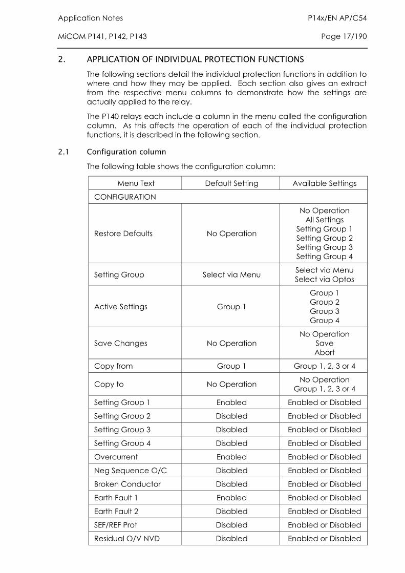
Application Notes P14x/EN AP/C54 MiCOM P141, P142, P143 Page 17/190
2. APPLICATION OF INDIVIDUAL PROTECTION FUNCTIONS The following sections detail the individual protection functions in addition to where and how they may be applied. Each section also gives an extract from the respective menu columns to demonstrate how the settings are actually applied to the relay.
The P140 relays each include a column in the menu called the configuration column. As this affects the operation of each of the individual protection functions, it is described in the following section.
2.1 Configuration column The following table shows the configuration column:
Menu Text Default Setting Available Settings
CONFIGURATION
Restore Defaults No Operation
No Operation All Settings
Setting Group 1 Setting Group 2 Setting Group 3 Setting Group 4
Setting Group Select via Menu Select via Menu Select via Optos
Active Settings Group 1
Group 1 Group 2 Group 3 Group 4
Save Changes No Operation No Operation
Save Abort
Copy from Group 1 Group 1, 2, 3 or 4
Copy to No Operation No Operation Group 1, 2, 3 or 4
Setting Group 1 Enabled Enabled or Disabled
Setting Group 2 Disabled Enabled or Disabled
Setting Group 3 Disabled Enabled or Disabled
Setting Group 4 Disabled Enabled or Disabled
Overcurrent Enabled Enabled or Disabled
Neg Sequence O/C Disabled Enabled or Disabled
Broken Conductor Disabled Enabled or Disabled
Earth Fault 1 Enabled Enabled or Disabled
Earth Fault 2 Disabled Enabled or Disabled
SEF/REF Prot Disabled Enabled or Disabled
Residual O/V NVD Disabled Enabled or Disabled
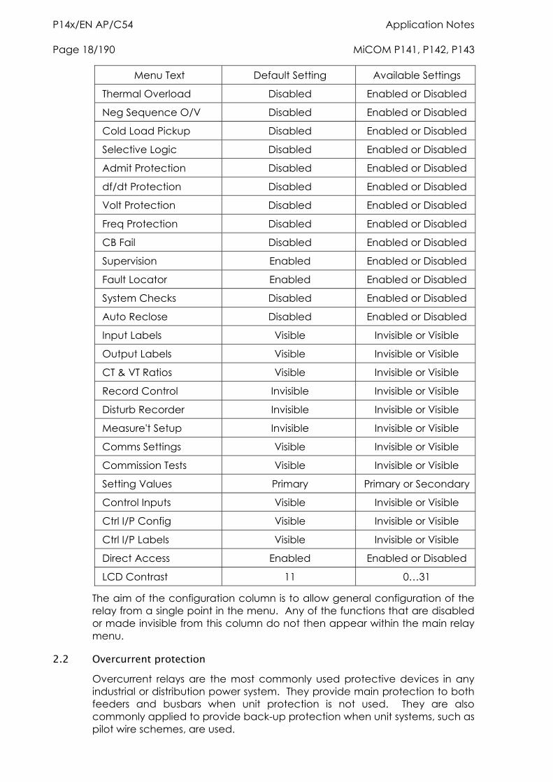
P14x/EN AP/C54 Application Notes Page 18/190 MiCOM P141, P142, P143
Menu Text Default Setting Available Settings
Thermal Overload Disabled Enabled or Disabled
Neg Sequence O/V Disabled Enabled or Disabled
Cold Load Pickup Disabled Enabled or Disabled
Selective Logic Disabled Enabled or Disabled
Admit Protection Disabled Enabled or Disabled
df/dt Protection Disabled Enabled or Disabled
Volt Protection Disabled Enabled or Disabled
Freq Protection Disabled Enabled or Disabled
CB Fail Disabled Enabled or Disabled
Supervision Enabled Enabled or Disabled
Fault Locator Enabled Enabled or Disabled
System Checks Disabled Enabled or Disabled
Auto Reclose Disabled Enabled or Disabled
Input Labels Visible Invisible or Visible
Output Labels Visible Invisible or Visible
CT & VT Ratios Visible Invisible or Visible
Record Control Invisible Invisible or Visible
Disturb Recorder Invisible Invisible or Visible
Measure't Setup Invisible Invisible or Visible
Comms Settings Visible Invisible or Visible
Commission Tests Visible Invisible or Visible
Setting Values Primary Primary or Secondary
Control Inputs Visible Invisible or Visible
Ctrl I/P Config Visible Invisible or Visible
Ctrl I/P Labels Visible Invisible or Visible
Direct Access Enabled Enabled or Disabled
LCD Contrast 11 0…31
The aim of the configuration column is to allow general configuration of the relay from a single point in the menu. Any of the functions that are disabled or made invisible from this column do not then appear within the main relay menu.
2.2 Overcurrent protection Overcurrent relays are the most commonly used protective devices in any industrial or distribution power system. They provide main protection to both feeders and busbars when unit protection is not used. They are also commonly applied to provide back-up protection when unit systems, such as pilot wire schemes, are used.
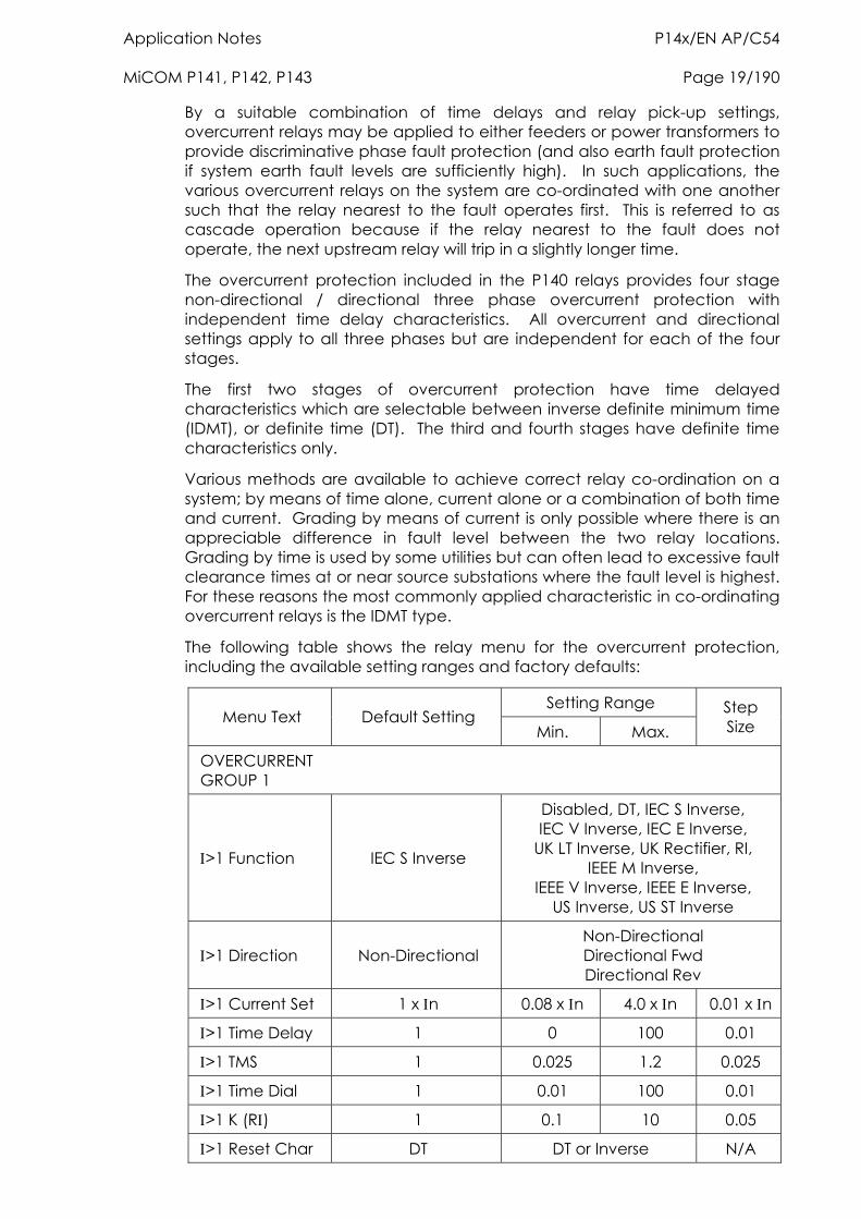
Application Notes P14x/EN AP/C54 MiCOM P141, P142, P143 Page 19/190
By a suitable combination of time delays and relay pick-up settings, overcurrent relays may be applied to either feeders or power transformers to provide discriminative phase fault protection (and also earth fault protection if system earth fault levels are sufficiently high). In such applications, the various overcurrent relays on the system are co-ordinated with one another such that the relay nearest to the fault operates first. This is referred to as cascade operation because if the relay nearest to the fault does not operate, the next upstream relay will trip in a slightly longer time.
The overcurrent protection included in the P140 relays provides four stage non-directional / directional three phase overcurrent protection with independent time delay characteristics. All overcurrent and directional settings apply to all three phases but are independent for each of the four stages.
The first two stages of overcurrent protection have time delayed characteristics which are selectable between inverse definite minimum time (IDMT), or definite time (DT). The third and fourth stages have definite time characteristics only.
Various methods are available to achieve correct relay co-ordination on a system; by means of time alone, current alone or a combination of both time and current. Grading by means of current is only possible where there is an appreciable difference in fault level between the two relay locations. Grading by time is used by some utilities but can often lead to excessive fault clearance times at or near source substations where the fault level is highest. For these reasons the most commonly applied characteristic in co-ordinating overcurrent relays is the IDMT type.
The following table shows the relay menu for the overcurrent protection, including the available setting ranges and factory defaults:
Setting Range Menu Text Default Setting
Min. Max. Step Size
OVERCURRENT GROUP 1
>1 Function IEC S Inverse
Disabled, DT, IEC S Inverse, IEC V Inverse, IEC E Inverse,
UK LT Inverse, UK Rectifier, RI, IEEE M Inverse,
IEEE V Inverse, IEEE E Inverse, US Inverse, US ST Inverse
>1 Direction Non-Directional Non-Directional Directional Fwd Directional Rev
>1 Current Set 1 x n 0.08 x n 4.0 x n 0.01 x n
>1 Time Delay 1 0 100 0.01
>1 TMS 1 0.025 1.2 0.025
>1 Time Dial 1 0.01 100 0.01
>1 K (R) 1 0.1 10 0.05
>1 Reset Char DT DT or Inverse N/A
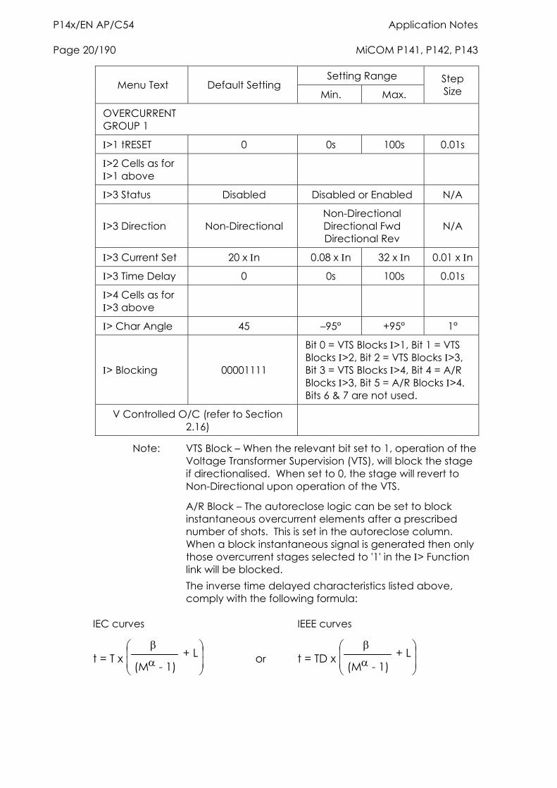
P14x/EN AP/C54 Application Notes Page 20/190 MiCOM P141, P142, P143
Setting Range Menu Text Default Setting
Min. Max. Step Size
OVERCURRENT GROUP 1
>1 tRESET 0 0s 100s 0.01s
>2 Cells as for >1 above
>3 Status Disabled Disabled or Enabled N/A
>3 Direction Non-Directional Non-Directional Directional Fwd Directional Rev
N/A
>3 Current Set 20 x n 0.08 x n 32 x n 0.01 x n
>3 Time Delay 0 0s 100s 0.01s
>4 Cells as for >3 above
> Char Angle 45 –95° +95° 1°
> Blocking 00001111
Bit 0 = VTS Blocks >1, Bit 1 = VTS Blocks >2, Bit 2 = VTS Blocks >3, Bit 3 = VTS Blocks >4, Bit 4 = A/R Blocks >3, Bit 5 = A/R Blocks >4. Bits 6 & 7 are not used.
V Controlled O/C (refer to Section 2.16)
Note: VTS Block – When the relevant bit set to 1, operation of the Voltage Transformer Supervision (VTS), will block the stage if directionalised. When set to 0, the stage will revert to Non-Directional upon operation of the VTS.
A/R Block – The autoreclose logic can be set to block instantaneous overcurrent elements after a prescribed number of shots. This is set in the autoreclose column. When a block instantaneous signal is generated then only those overcurrent stages selected to '1' in the > Function link will be blocked.
The inverse time delayed characteristics listed above, comply with the following formula:
IEC curves IEEE curves
t = T x
(M - 1) + L or t = TD x
(M - 1) + L
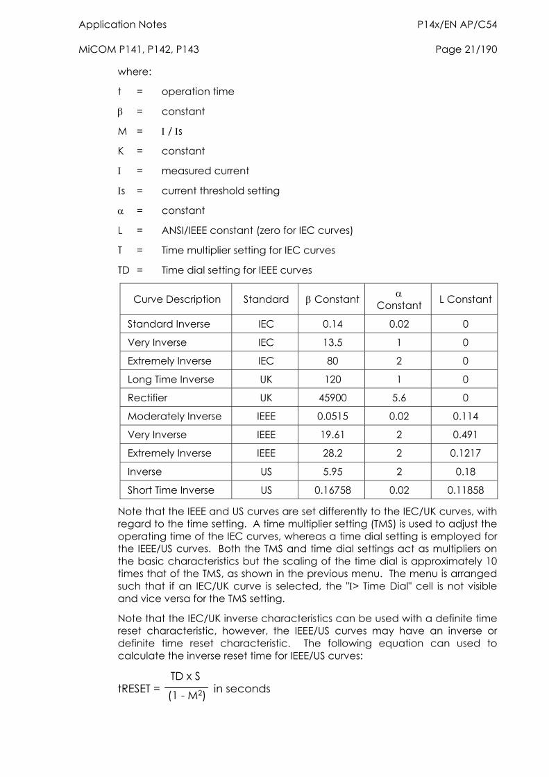
Application Notes P14x/EN AP/C54 MiCOM P141, P142, P143 Page 21/190
where:
t = operation time
= constant
M = / s
K = constant
= measured current
s = current threshold setting
= constant
L = ANSI/IEEE constant (zero for IEC curves)
T = Time multiplier setting for IEC curves
TD = Time dial setting for IEEE curves
Curve Description Standard Constant Constant L Constant
Standard Inverse IEC 0.14 0.02 0
Very Inverse IEC 13.5 1 0
Extremely Inverse IEC 80 2 0
Long Time Inverse UK 120 1 0
Rectifier UK 45900 5.6 0
Moderately Inverse IEEE 0.0515 0.02 0.114
Very Inverse IEEE 19.61 2 0.491
Extremely Inverse IEEE 28.2 2 0.1217
Inverse US 5.95 2 0.18
Short Time Inverse US 0.16758 0.02 0.11858
Note that the IEEE and US curves are set differently to the IEC/UK curves, with regard to the time setting. A time multiplier setting (TMS) is used to adjust the operating time of the IEC curves, whereas a time dial setting is employed for the IEEE/US curves. Both the TMS and time dial settings act as multipliers on the basic characteristics but the scaling of the time dial is approximately 10 times that of the TMS, as shown in the previous menu. The menu is arranged such that if an IEC/UK curve is selected, the "> Time Dial" cell is not visible and vice versa for the TMS setting.
Note that the IEC/UK inverse characteristics can be used with a definite time reset characteristic, however, the IEEE/US curves may have an inverse or definite time reset characteristic. The following equation can used to calculate the inverse reset time for IEEE/US curves:
tRESET = TD x S
(1 - M2) in seconds
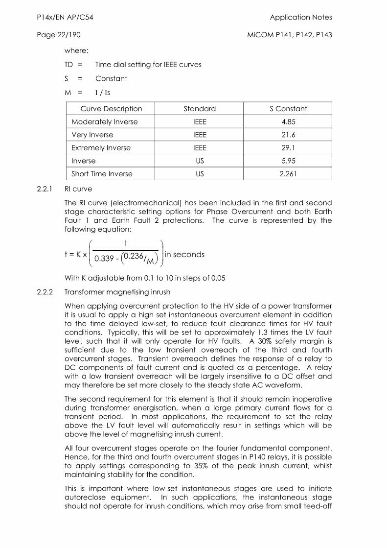
P14x/EN AP/C54 Application Notes Page 22/190 MiCOM P141, P142, P143
where:
TD = Time dial setting for IEEE curves
S = Constant
M = / s
Curve Description Standard S Constant
Moderately Inverse IEEE 4.85
Very Inverse IEEE 21.6
Extremely Inverse IEEE 29.1
Inverse US 5.95
Short Time Inverse US 2.261
2.2.1 RI curve
The RI curve (electromechanical) has been included in the first and second stage characteristic setting options for Phase Overcurrent and both Earth Fault 1 and Earth Fault 2 protections. The curve is represented by the following equation:
t = K x
1
0.339 - 0.236/M
in seconds
With K adjustable from 0.1 to 10 in steps of 0.05
2.2.2 Transformer magnetising inrush
When applying overcurrent protection to the HV side of a power transformer it is usual to apply a high set instantaneous overcurrent element in addition to the time delayed low-set, to reduce fault clearance times for HV fault conditions. Typically, this will be set to approximately 1.3 times the LV fault level, such that it will only operate for HV faults. A 30% safety margin is sufficient due to the low transient overreach of the third and fourth overcurrent stages. Transient overreach defines the response of a relay to DC components of fault current and is quoted as a percentage. A relay with a low transient overreach will be largely insensitive to a DC offset and may therefore be set more closely to the steady state AC waveform.
The second requirement for this element is that it should remain inoperative during transformer energisation, when a large primary current flows for a transient period. In most applications, the requirement to set the relay above the LV fault level will automatically result in settings which will be above the level of magnetising inrush current.
All four overcurrent stages operate on the fourier fundamental component. Hence, for the third and fourth overcurrent stages in P140 relays, it is possible to apply settings corresponding to 35% of the peak inrush current, whilst maintaining stability for the condition.
This is important where low-set instantaneous stages are used to initiate autoreclose equipment. In such applications, the instantaneous stage should not operate for inrush conditions, which may arise from small teed-off
Application Notes P14x/EN AP/C54 MiCOM P141, P142, P143 Page 23/190
transformer loads for example. However, the setting must also be sensitive enough to provide fast operation under fault conditions.
Where an instantaneous element is required to accompany the time delayed protection, as described above, the third or fourth overcurrent stage of the P140 relay should be used, as they have wider setting ranges.
2.2.3 Application of timer hold facility
The first two stages of overcurrent protection in the P140 relays are provided with a timer hold facility, which may either be set to zero or to a definite time value. Setting of the timer to zero means that the overcurrent timer for that stage will reset instantaneously once the current falls below 95% of the current setting. Setting of the hold timer to a value other than zero, delays the resetting of the protection element timers for this period. This may be useful in certain applications, for example when grading with upstream electromechanical overcurrent relays, which have inherent reset time delays.
Another possible situation where the timer hold facility may be used to reduce fault clearance times is where intermittent faults may be experienced. An example of this may occur in a plastic insulated cable. In this application it is possible that the fault energy melts and reseals the cable insulation, thereby extinguishing the fault. This process repeats to give a succession of fault current pulses, each of increasing duration with reducing intervals between the pulses, until the fault becomes permanent.
When the reset time of the overcurrent relay is instantaneous, the relay will be repeatedly reset and not be able to trip until the fault becomes permanent. By using the Timer Hold facility the relay will integrate the fault current pulses, thereby reducing fault clearance time.
The timer hold facility can be found for the first and second overcurrent stages as settings ">1 tRESET" and ">2 tRESET", respectively. Note that this cell is not visible for the IEEE/US curves if an inverse time reset characteristic has been selected, as the reset time is then determined by the programmed time dial setting.
2.2.4 Setting guidelines
When applying the overcurrent protection provided in the P140 relays, standard principles should be applied in calculating the necessary current and time settings for co-ordination. The setting example detailed below shows a typical setting calculation and describes how the settings are actually applied to the relay.
Assume the following parameters for a relay feeding an LV switchboard:
CT Ratio = 500/1
Full load current of circuit = 450A
Slowest downstream protection = 100A Fuse
The current setting employed on the P140 relay must account for both the maximum load current and the reset ratio of the relay itself:
> must be greater than: 450/0.95 = 474A
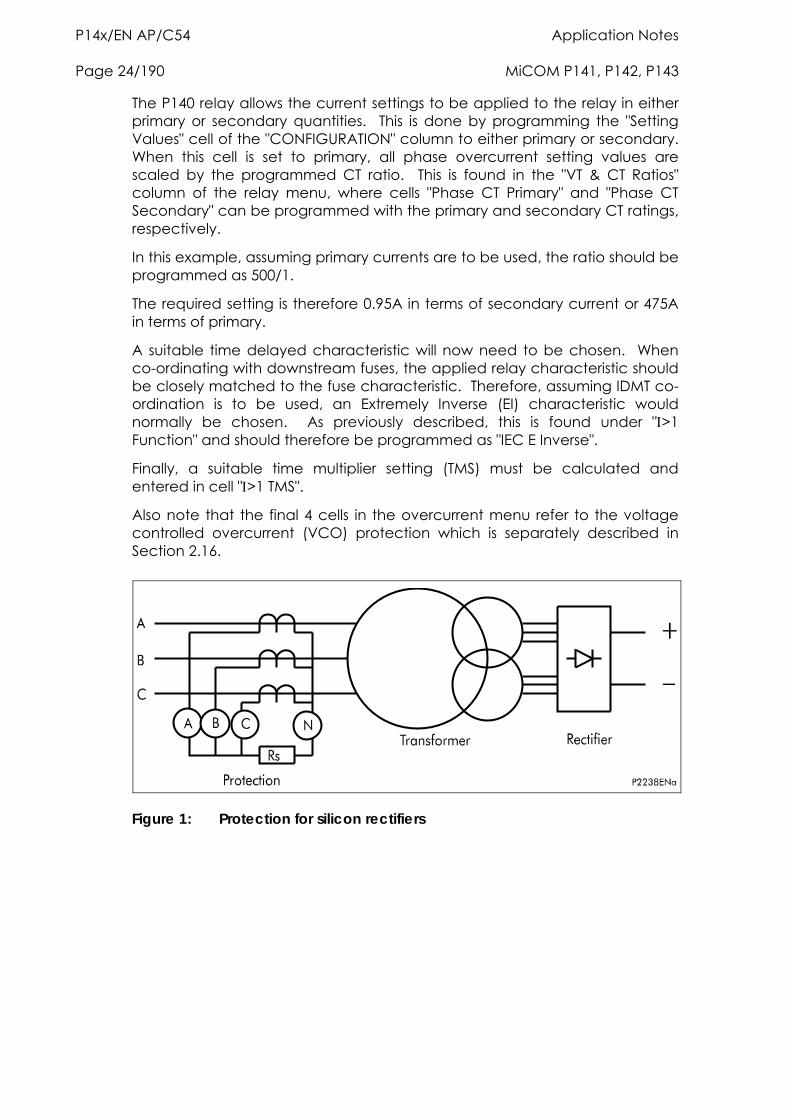
P14x/EN AP/C54 Application Notes Page 24/190 MiCOM P141, P142, P143
The P140 relay allows the current settings to be applied to the relay in either primary or secondary quantities. This is done by programming the "Setting Values" cell of the "CONFIGURATION" column to either primary or secondary. When this cell is set to primary, all phase overcurrent setting values are scaled by the programmed CT ratio. This is found in the "VT & CT Ratios" column of the relay menu, where cells "Phase CT Primary" and "Phase CT Secondary" can be programmed with the primary and secondary CT ratings, respectively.
In this example, assuming primary currents are to be used, the ratio should be programmed as 500/1.
The required setting is therefore 0.95A in terms of secondary current or 475A in terms of primary.
A suitable time delayed characteristic will now need to be chosen. When co-ordinating with downstream fuses, the applied relay characteristic should be closely matched to the fuse characteristic. Therefore, assuming IDMT co-ordination is to be used, an Extremely Inverse (EI) characteristic would normally be chosen. As previously described, this is found under ">1 Function" and should therefore be programmed as "IEC E Inverse".
Finally, a suitable time multiplier setting (TMS) must be calculated and entered in cell ">1 TMS".
Also note that the final 4 cells in the overcurrent menu refer to the voltage controlled overcurrent (VCO) protection which is separately described in Section 2.16.
Figure 1: Protection for silicon rectifiers
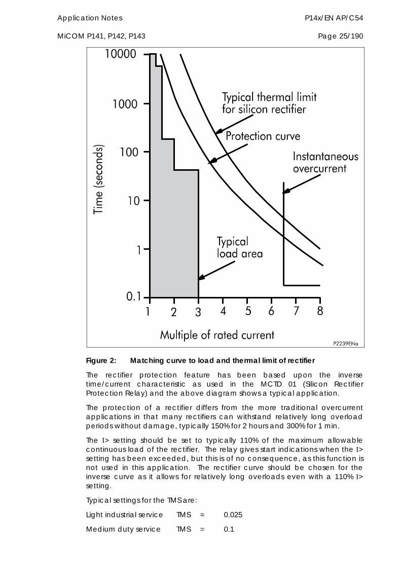
Application Notes P14x/EN AP/C54 MiCOM P141, P142, P143 Page 25/190
Figure 2: Matching curve to load and thermal limit of rectifier
The rectifier protection feature has been based upon the inverse time/current characteristic as used in the MCTD 01 (Silicon Rectifier Protection Relay) and the above diagram shows a typical application.
The protection of a rectifier differs from the more traditional overcurrent applications in that many rectifiers can withstand relatively long overload periods without damage, typically 150% for 2 hours and 300% for 1 min.
The > setting should be set to typically 110% of the maximum allowable continuous load of the rectifier. The relay gives start indications when the > setting has been exceeded, but this is of no consequence, as this function is not used in this application. The rectifier curve should be chosen for the inverse curve as it allows for relatively long overloads even with a 110% > setting.
Typical settings for the TMS are:
Light industrial service TMS = 0.025
Medium duty service TMS = 0.1
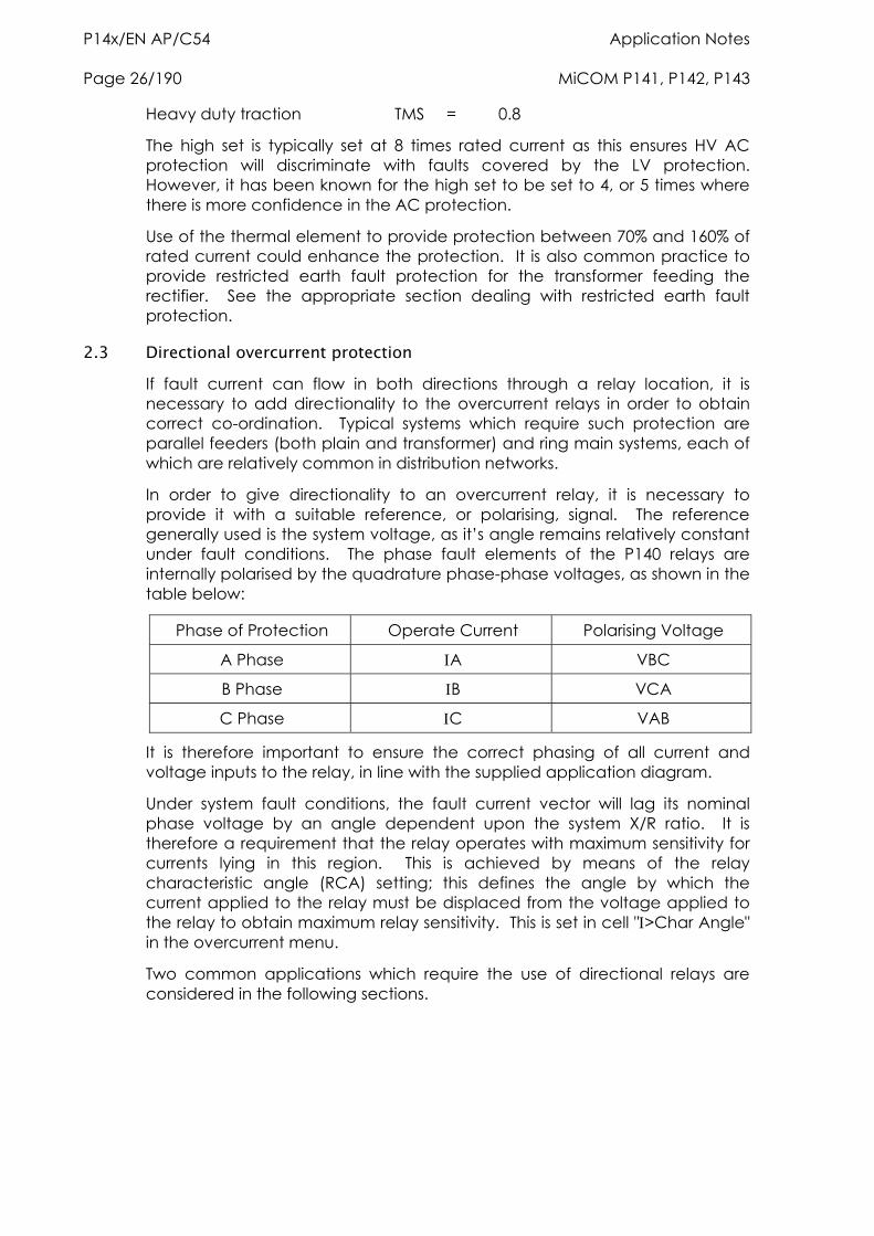
P14x/EN AP/C54 Application Notes Page 26/190 MiCOM P141, P142, P143
Heavy duty traction TMS = 0.8
The high set is typically set at 8 times rated current as this ensures HV AC protection will discriminate with faults covered by the LV protection. However, it has been known for the high set to be set to 4, or 5 times where there is more confidence in the AC protection.
Use of the thermal element to provide protection between 70% and 160% of rated current could enhance the protection. It is also common practice to provide restricted earth fault protection for the transformer feeding the rectifier. See the appropriate section dealing with restricted earth fault protection.
2.3 Directional overcurrent protection If fault current can flow in both directions through a relay location, it is necessary to add directionality to the overcurrent relays in order to obtain correct co-ordination. Typical systems which require such protection are parallel feeders (both plain and transformer) and ring main systems, each of which are relatively common in distribution networks.
In order to give directionality to an overcurrent relay, it is necessary to provide it with a suitable reference, or polarising, signal. The reference generally used is the system voltage, as it’s angle remains relatively constant under fault conditions. The phase fault elements of the P140 relays are internally polarised by the quadrature phase-phase voltages, as shown in the table below:
Phase of Protection Operate Current Polarising Voltage
A Phase A VBC
B Phase B VCA
C Phase C VAB
It is therefore important to ensure the correct phasing of all current and voltage inputs to the relay, in line with the supplied application diagram.
Under system fault conditions, the fault current vector will lag its nominal phase voltage by an angle dependent upon the system X/R ratio. It is therefore a requirement that the relay operates with maximum sensitivity for currents lying in this region. This is achieved by means of the relay characteristic angle (RCA) setting; this defines the angle by which the current applied to the relay must be displaced from the voltage applied to the relay to obtain maximum relay sensitivity. This is set in cell ">Char Angle" in the overcurrent menu.
Two common applications which require the use of directional relays are considered in the following sections.
Application Notes P14x/EN AP/C54 MiCOM P141, P142, P143 Page 27/190
2.3.1 Parallel feeders
Figure 3: Typical distribution system using parallel transformers
Figure 3 shows a typical distribution system utilising parallel power transformers. In such an application, a fault at ‘F’ could result in the operation of both R3 and R4 relays and the subsequent loss of supply to the 11kV busbar. Hence, with this system configuration, it is necessary to apply directional relays at these locations set to 'look into' their respective transformers. These relays should co-ordinate with the non-directional relays, R1 and R2; hence ensuring discriminative relay operation during such fault conditions.
In such an application, relays R3 and R4 may commonly require non-directional overcurrent protection elements to provide protection to the 11kV busbar, in addition to providing a back-up function to the overcurrent relays on the outgoing feeders (R5).
P14x/EN AP/C54 Application Notes Page 28/190 MiCOM P141, P142, P143
When applying the P140 relays in the above application, stage 1 of the overcurrent protection of relays R3 and R4 would be set non-directional and time graded with R5, using an appropriate time delay characteristic. Stage 2 could then be set directional, looking back into the transformer, also having a characteristic which provided correct co-ordination with R1 and R2 IDMT or DT characteristics are selectable for both stages 1 and 2 and directionality of each of the overcurrent stages is set in cell "> Direction".
Note that the principles previously outlined for the parallel transformer application are equally applicable for plain feeders which are operating in parallel.
2.3.2 Ring main arrangements
A particularly common arrangement within distribution networks is the ring main circuit. The primary reason for its use is to maintain supplies to consumer’s in the event of fault conditions occurring on the interconnecting feeders. A typical ring main with associated overcurrent protection is shown in Figure 4.
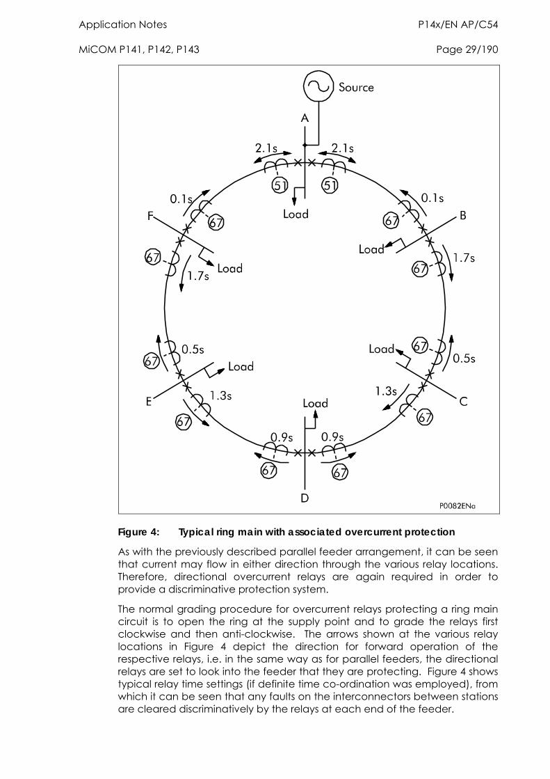
Application Notes P14x/EN AP/C54 MiCOM P141, P142, P143 Page 29/190
Figure 4: Typical ring main with associated overcurrent protection
As with the previously described parallel feeder arrangement, it can be seen that current may flow in either direction through the various relay locations. Therefore, directional overcurrent relays are again required in order to provide a discriminative protection system.
The normal grading procedure for overcurrent relays protecting a ring main circuit is to open the ring at the supply point and to grade the relays first clockwise and then anti-clockwise. The arrows shown at the various relay locations in Figure 4 depict the direction for forward operation of the respective relays, i.e. in the same way as for parallel feeders, the directional relays are set to look into the feeder that they are protecting. Figure 4 shows typical relay time settings (if definite time co-ordination was employed), from which it can be seen that any faults on the interconnectors between stations are cleared discriminatively by the relays at each end of the feeder.
P14x/EN AP/C54 Application Notes Page 30/190 MiCOM P141, P142, P143
Again, any of the four overcurrent stages may be configured to be directional and co-ordinated as per the previously outlined grading procedure, noting that IDMT characteristics are only selectable on the first two stages.
2.3.3 Synchronous polarisation
For a fault condition which occurs close to the relaying point, the faulty phase voltage will reduce to a value close to zero volts. For single or double phase faults, there will always be at least one healthy phase voltage present for polarisation of the phase overcurrent elements. For example, a close up A to B fault condition will result in the collapse of the A and B phase voltages. However, the A and B phase elements are polarised from VBC and VCA respectively. As such a polarising signal will be present, allowing correct relay operation.
For a close up three phase fault, all three voltages will collapse to zero and no healthy phase voltages will be present. For this reason, the P140 relays include a synchronous polarisation feature which stores the pre-fault voltage information and continues to apply it to the directional overcurrent elements for a time period of 3.2 seconds. This ensures that either instantaneous or time delayed directional overcurrent elements will be allowed to operate, even with a three phase voltage collapse.
2.3.4 Setting guidelines
The applied current settings for directional overcurrent relays are dependent upon the application in question. In a parallel feeder arrangement, load current is always flowing in the non-operate direction. Hence, the relay current setting may be less than the full load rating of the circuit; typically 50% of n.
Note that the minimum setting that may be applied has to take into account the thermal rating of the relay. Some electro-mechanical directional overcurrent relays have continuous withstand ratings of only twice the applied current setting and hence 50% of rating was the minimum setting that could be applied. With the P140, the continuous current rating is 4 x rated current and so it is possible to apply much more sensitive settings if required. However, there are minimum safe current setting constraints to be observed when applying directional overcurrent protection at the receiving-ends of parallel feeders. The minimum safe settings to ensure that there is no possibility of an unwanted trip during clearance of a source fault are as follows for linear system load:
Parallel plain feeders:
Set>50% Prefault load current
Parallel transformer feeders:
Set>87% Prefault load current
When the above setting constraints are infringed, independent-time protection is more likely to issue an unwanted trip during clearance of a source fault than dependent-time protection.
Where the above setting constraints are unavoidably infringed, secure phase fault protection can be provided with relays which have 2-out-of-3 directional protection tripping logic.
Application Notes P14x/EN AP/C54 MiCOM P141, P142, P143 Page 31/190
A common minimum current setting recommendation (50% relay rated current) would be virtually safe for plain parallel feeder protection as long as the circuit load current does not exceed 100% relay rated current. It would also be safe for parallel transformer feeders, if the system design criterion for two feeders is such that the load on each feeder will never exceed 50% rated current with both feeders in service. For more than two feeders in parallel the 50% relay rated current setting may not be absolutely safe.
In a ring main application, it is possible for load current to flow in either direction through the relaying point. Hence, the current setting must be above the maximum load current, as in a standard non-directional application.
The required characteristic angle settings for directional relays will differ depending on the exact application in which they are used. Recommended characteristic angle settings are as follows:-
Plain feeders, or applications with an earthing point (zero sequence source) behind the relay location, should utilise a +30° RCA setting.
Transformer feeders, or applications with a zero sequence source in front of the relay location, should utilise a +45° RCA setting.
On the P140 relays, it is possible to set characteristic angles anywhere in the range –95° to +95°. Whilst it is possible to set the RCA to exactly match the system fault angle, it is recommended that the above guidelines are adhered to, as these settings have been shown to provide satisfactory performance and stability under a wide range of system conditions.
2.4 Thermal overload protection Thermal overload protection can be used to prevent electrical plant from operating at temperatures in excess of the designed maximum withstand. Prolonged overloading causes excessive heating, which may result in premature ageing of the insulation, or in extreme cases, insulation failure.
The relay incorporates a current based thermal replica, using rms load current to model heating and cooling of the protected plant. The element can be set with both alarm and trip stages.
The heat generated within an item of plant, such as a cable or a transformer, is the resistive loss (2R x t). Thus, heating is directly proportional to current squared. The thermal time characteristic used in the relay is therefore based on current squared, integrated over time. The relay automatically uses the largest phase current for input to the thermal model.
Equipment is designed to operate continuously at a temperature corresponding to its full load rating, where heat generated is balanced with heat dissipated by radiation etc. Overtemperature conditions therefore occur when currents in excess of rating are allowed to flow for a period of time. It can be shown that temperatures during heating follow exponential time constants and a similar exponential decrease of temperature occurs during cooling.
In order to apply this protection element, the thermal time constant for the protected item of plant is therefore required.
The following sections will show that different items of plant possess different thermal characteristics, due to the nature of their construction. The relay
P14x/EN AP/C54 Application Notes Page 32/190 MiCOM P141, P142, P143
provides two characteristics which may be selected according to the application.
2.4.1 Single time constant characteristic
This characteristic is used to protect cables, dry type transformers (e.g. type AN), and capacitor banks.
The thermal time characteristic is given by:
t = - loge
2 - (K.FLC)2
(2 - p2)
where:
t = Time to trip, following application of the overload current, ;
= Heating and cooling time constant of the protected plant;
= Largest phase current;
FLC = Full load current rating (relay setting ‘Thermal Trip’);
k = 1.05 constant, allows continuous operation up to <1.05 FLC.
P = Steady state pre-loading before application of the overload.
The time to trip varies depending on the load current carried before application of the overload, i.e. whether the overload was applied from 'hot” or “cold”.
The thermal time constant characteristic may be rewritten as:
e(-t/)=
- p
- 1
where:
= 2/k2FLC2
and
p = p2/k2FLC2
where is the thermal state and is p the prefault thermal state.
Note: A current of 105%s (kFLC) has to be applied for several time constants to cause a thermal state measurement of 100%
2.4.2 Dual time constant characteristic
This characteristic is used to protect oil-filled transformers with natural air cooling (e.g. type ONAN). The thermal model is similar to that with the single time constant, except that two timer constants must be set.
For marginal overloading, heat will flow from the windings into the bulk of the insulating oil. Thus, at low current, the replica curve is dominated by the long time constant for the oil. This provides protection against a general rise in oil temperature.

Application Notes P14x/EN AP/C54 MiCOM P141, P142, P143 Page 33/190
For severe overloading, heat accumulates in the transformer windings, with little opportunity for dissipation into the surrounding insulating oil. Thus, at high current, the replica curve is dominated by the short time constant for the windings. This provides protection against hot spots developing within the transformer windings.
Overall, the dual time constant characteristic provided within the relay serves to protect the winding insulation from ageing, and to minimise gas production by overheated oil. Note, however, that the thermal model does not compensate for the effects of ambient temperature change.
The thermal curve is defined as:
0.4e(-t/) + 0.6e(-t/) = 2 - (k.FLC)2
2 - p2
where:
1 = Heating and cooling time constant of the transformer windings;
2 = Heating and cooling time constant for the insulating oil.
In practice, it is difficult to solve this equation to give the operating time (t), therefore a graphical solution, using a spreadsheet package, is recommended. The spreadsheet can be arranged to calculate the current that will give a chosen operating time. The equation to calculate the current is defined as:
=0.4p2.e(-t/1) + 0.6p2.e(-t/2) -k2.FLC
2
0.4 e(-t/1) + 0.6 e(-t/2) -1 …….. Equation 1
Figure 5 below shows how this equation can be used within a spreadsheet to calculate the relay operating time.
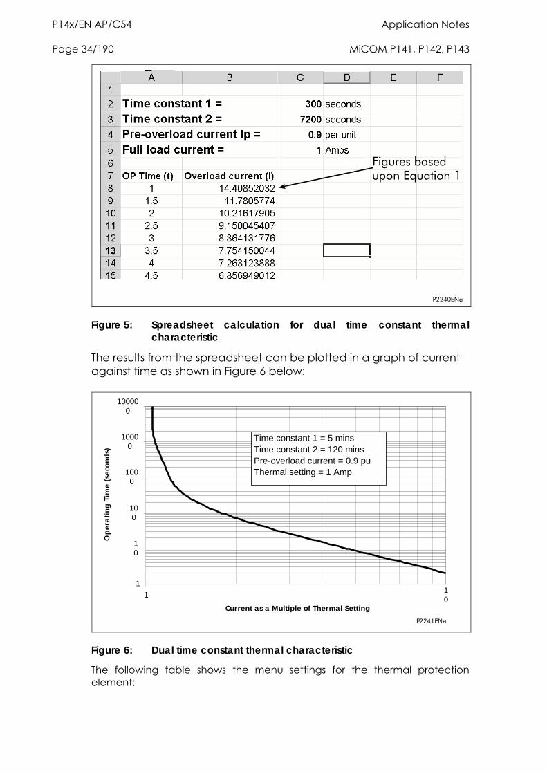
P14x/EN AP/C54 Application Notes Page 34/190 MiCOM P141, P142, P143
Figure 5: Spreadsheet calculation for dual time constant thermal characteristic
The results from the spreadsheet can be plotted in a graph of current against time as shown in Figure 6 below:
1
10
100
1000
10000
100000
110
Current as a Multiple of Thermal Setting
Op
era
tin
g T
ime
(se
con
ds)
Time constant 1 = 5 minsTime constant 2 = 120 minsPre-overload current = 0.9 puThermal setting = 1 Amp
P2241ENa
Figure 6: Dual time constant thermal characteristic
The following table shows the menu settings for the thermal protection element:
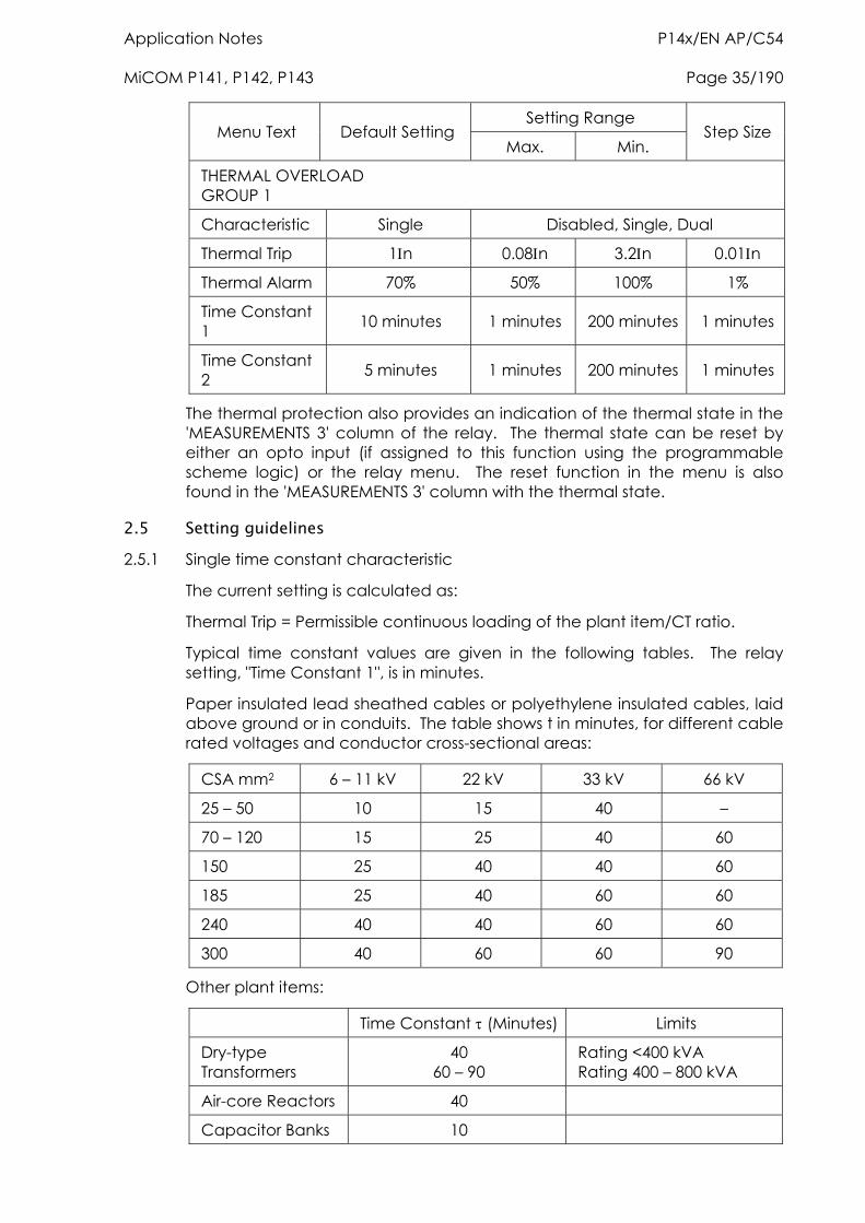
Application Notes P14x/EN AP/C54 MiCOM P141, P142, P143 Page 35/190
Setting Range Menu Text Default Setting
Max. Min. Step Size
THERMAL OVERLOAD GROUP 1
Characteristic Single Disabled, Single, Dual
Thermal Trip 1n 0.08n 3.2n 0.01n
Thermal Alarm 70% 50% 100% 1%
Time Constant 1 10 minutes 1 minutes 200 minutes 1 minutes
Time Constant 2 5 minutes 1 minutes 200 minutes 1 minutes
The thermal protection also provides an indication of the thermal state in the 'MEASUREMENTS 3' column of the relay. The thermal state can be reset by either an opto input (if assigned to this function using the programmable scheme logic) or the relay menu. The reset function in the menu is also found in the 'MEASUREMENTS 3' column with the thermal state.
2.5 Setting guidelines 2.5.1 Single time constant characteristic
The current setting is calculated as:
Thermal Trip = Permissible continuous loading of the plant item/CT ratio.
Typical time constant values are given in the following tables. The relay setting, "Time Constant 1", is in minutes.
Paper insulated lead sheathed cables or polyethylene insulated cables, laid above ground or in conduits. The table shows t in minutes, for different cable rated voltages and conductor cross-sectional areas:
CSA mm2 6 – 11 kV 22 kV 33 kV 66 kV
25 – 50 10 15 40 –
70 – 120 15 25 40 60
150 25 40 40 60
185 25 40 60 60
240 40 40 60 60
300 40 60 60 90
Other plant items:
Time Constant (Minutes) Limits
Dry-type Transformers
40 60 – 90
Rating <400 kVA Rating 400 – 800 kVA
Air-core Reactors 40
Capacitor Banks 10
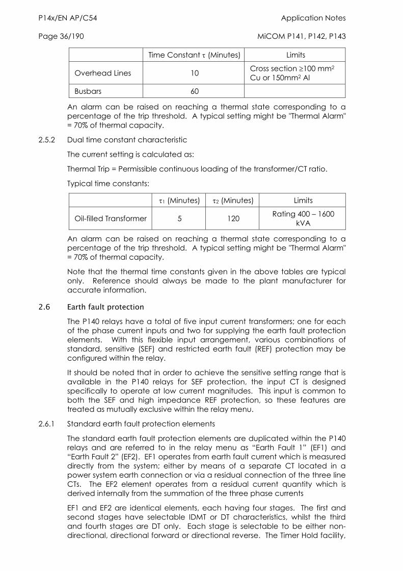
P14x/EN AP/C54 Application Notes Page 36/190 MiCOM P141, P142, P143
Time Constant (Minutes) Limits
Overhead Lines 10 Cross section 100 mm2
Cu or 150mm2 Al
Busbars 60
An alarm can be raised on reaching a thermal state corresponding to a percentage of the trip threshold. A typical setting might be "Thermal Alarm" = 70% of thermal capacity.
2.5.2 Dual time constant characteristic
The current setting is calculated as:
Thermal Trip = Permissible continuous loading of the transformer/CT ratio.
Typical time constants:
1 (Minutes) 2 (Minutes) Limits
Oil-filled Transformer 5 120 Rating 400 – 1600 kVA
An alarm can be raised on reaching a thermal state corresponding to a percentage of the trip threshold. A typical setting might be "Thermal Alarm" = 70% of thermal capacity.
Note that the thermal time constants given in the above tables are typical only. Reference should always be made to the plant manufacturer for accurate information.
2.6 Earth fault protection The P140 relays have a total of five input current transformers; one for each of the phase current inputs and two for supplying the earth fault protection elements. With this flexible input arrangement, various combinations of standard, sensitive (SEF) and restricted earth fault (REF) protection may be configured within the relay.
It should be noted that in order to achieve the sensitive setting range that is available in the P140 relays for SEF protection, the input CT is designed specifically to operate at low current magnitudes. This input is common to both the SEF and high impedance REF protection, so these features are treated as mutually exclusive within the relay menu.
2.6.1 Standard earth fault protection elements
The standard earth fault protection elements are duplicated within the P140 relays and are referred to in the relay menu as “Earth Fault 1” (EF1) and “Earth Fault 2” (EF2). EF1 operates from earth fault current which is measured directly from the system; either by means of a separate CT located in a power system earth connection or via a residual connection of the three line CTs. The EF2 element operates from a residual current quantity which is derived internally from the summation of the three phase currents
EF1 and EF2 are identical elements, each having four stages. The first and second stages have selectable IDMT or DT characteristics, whilst the third and fourth stages are DT only. Each stage is selectable to be either non-directional, directional forward or directional reverse. The Timer Hold facility,
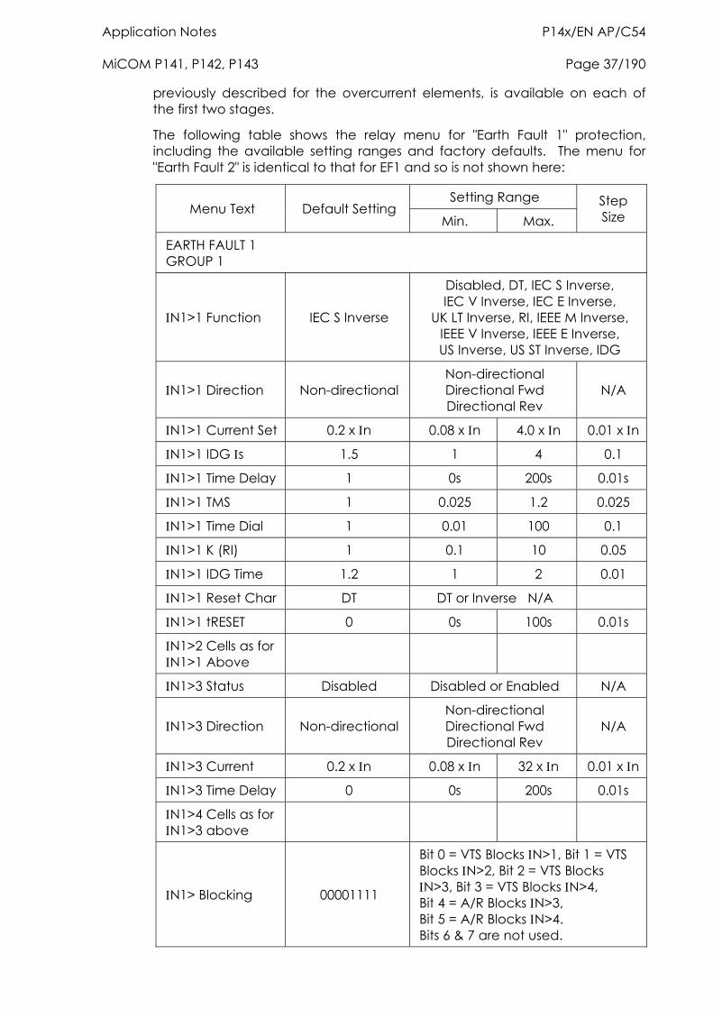
Application Notes P14x/EN AP/C54 MiCOM P141, P142, P143 Page 37/190
previously described for the overcurrent elements, is available on each of the first two stages.
The following table shows the relay menu for "Earth Fault 1" protection, including the available setting ranges and factory defaults. The menu for "Earth Fault 2" is identical to that for EF1 and so is not shown here:
Setting Range Menu Text Default Setting
Min. Max. Step Size
EARTH FAULT 1 GROUP 1
N1>1 Function IEC S Inverse
Disabled, DT, IEC S Inverse, IEC V Inverse, IEC E Inverse,
UK LT Inverse, RI, IEEE M Inverse, IEEE V Inverse, IEEE E Inverse, US Inverse, US ST Inverse, IDG
N1>1 Direction Non-directional Non-directional Directional Fwd Directional Rev
N/A
N1>1 Current Set 0.2 x n 0.08 x n 4.0 x n 0.01 x n
N1>1 IDG s 1.5 1 4 0.1
N1>1 Time Delay 1 0s 200s 0.01s
N1>1 TMS 1 0.025 1.2 0.025
N1>1 Time Dial 1 0.01 100 0.1
N1>1 K (RI) 1 0.1 10 0.05
N1>1 IDG Time 1.2 1 2 0.01
N1>1 Reset Char DT DT or Inverse N/A
N1>1 tRESET 0 0s 100s 0.01s
N1>2 Cells as for N1>1 Above
N1>3 Status Disabled Disabled or Enabled N/A
N1>3 Direction Non-directional Non-directional Directional Fwd Directional Rev
N/A
N1>3 Current 0.2 x n 0.08 x n 32 x n 0.01 x n
N1>3 Time Delay 0 0s 200s 0.01s
N1>4 Cells as for N1>3 above
N1> Blocking 00001111
Bit 0 = VTS Blocks N>1, Bit 1 = VTS Blocks N>2, Bit 2 = VTS Blocks N>3, Bit 3 = VTS Blocks N>4, Bit 4 = A/R Blocks N>3, Bit 5 = A/R Blocks N>4. Bits 6 & 7 are not used.
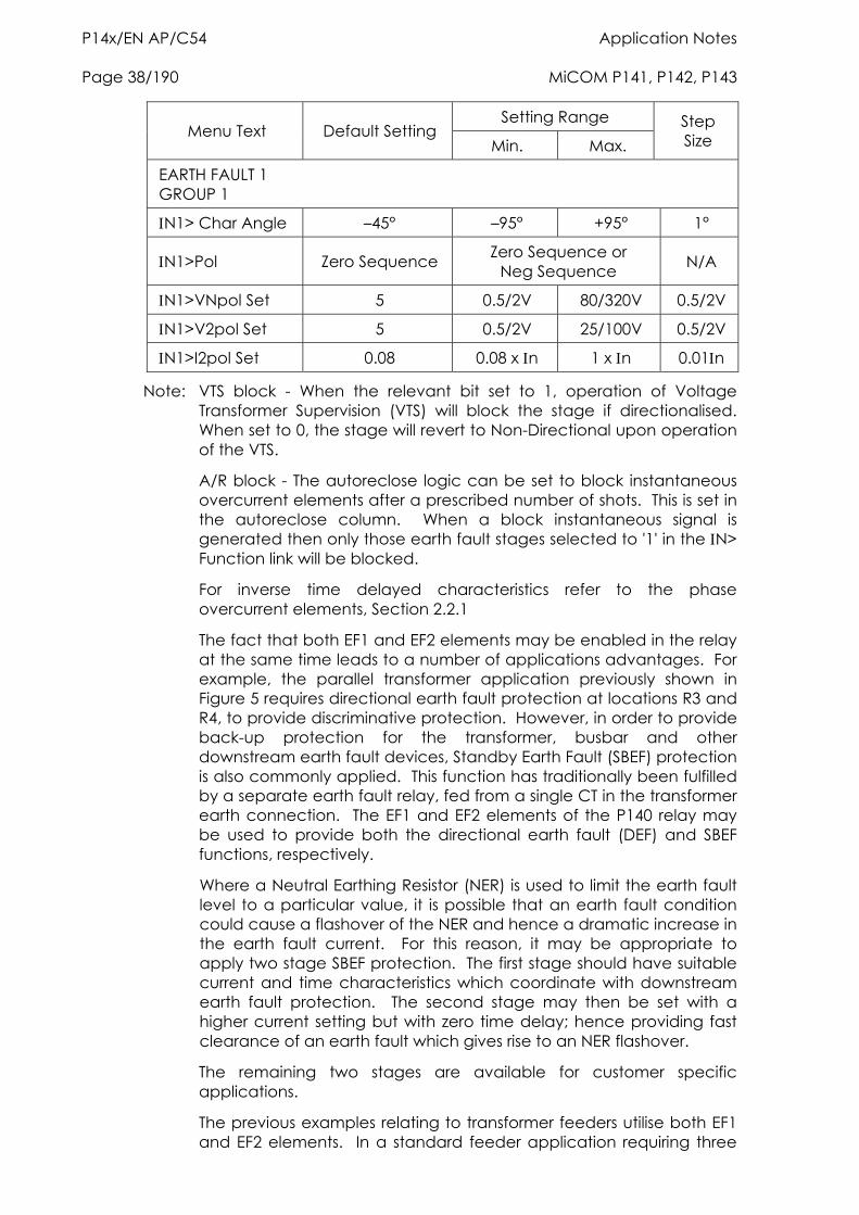
P14x/EN AP/C54 Application Notes Page 38/190 MiCOM P141, P142, P143
Setting Range Menu Text Default Setting
Min. Max. Step Size
EARTH FAULT 1 GROUP 1
N1> Char Angle –45° –95° +95° 1°
N1>Pol Zero Sequence Zero Sequence or Neg Sequence N/A
N1>VNpol Set 5 0.5/2V 80/320V 0.5/2V
N1>V2pol Set 5 0.5/2V 25/100V 0.5/2V
N1>I2pol Set 0.08 0.08 x n 1 x n 0.01n
Note: VTS block - When the relevant bit set to 1, operation of Voltage Transformer Supervision (VTS) will block the stage if directionalised. When set to 0, the stage will revert to Non-Directional upon operation of the VTS.
A/R block - The autoreclose logic can be set to block instantaneous overcurrent elements after a prescribed number of shots. This is set in the autoreclose column. When a block instantaneous signal is generated then only those earth fault stages selected to '1' in the N> Function link will be blocked.
For inverse time delayed characteristics refer to the phase overcurrent elements, Section 2.2.1
The fact that both EF1 and EF2 elements may be enabled in the relay at the same time leads to a number of applications advantages. For example, the parallel transformer application previously shown in Figure 5 requires directional earth fault protection at locations R3 and R4, to provide discriminative protection. However, in order to provide back-up protection for the transformer, busbar and other downstream earth fault devices, Standby Earth Fault (SBEF) protection is also commonly applied. This function has traditionally been fulfilled by a separate earth fault relay, fed from a single CT in the transformer earth connection. The EF1 and EF2 elements of the P140 relay may be used to provide both the directional earth fault (DEF) and SBEF functions, respectively.
Where a Neutral Earthing Resistor (NER) is used to limit the earth fault level to a particular value, it is possible that an earth fault condition could cause a flashover of the NER and hence a dramatic increase in the earth fault current. For this reason, it may be appropriate to apply two stage SBEF protection. The first stage should have suitable current and time characteristics which coordinate with downstream earth fault protection. The second stage may then be set with a higher current setting but with zero time delay; hence providing fast clearance of an earth fault which gives rise to an NER flashover.
The remaining two stages are available for customer specific applications.
The previous examples relating to transformer feeders utilise both EF1 and EF2 elements. In a standard feeder application requiring three
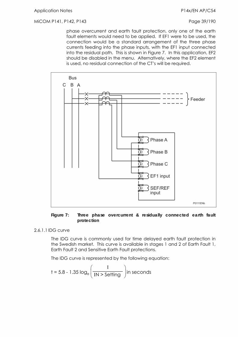
Application Notes P14x/EN AP/C54 MiCOM P141, P142, P143 Page 39/190
phase overcurrent and earth fault protection, only one of the earth fault elements would need to be applied. If EF1 were to be used, the connection would be a standard arrangement of the three phase currents feeding into the phase inputs, with the EF1 input connected into the residual path. This is shown in Figure 7. In this application, EF2 should be disabled in the menu. Alternatively, where the EF2 element is used, no residual connection of the CT’s will be required.
���
� � �
����
�� ����
�� ����
�� ����
���������
������������
��������
Figure 7: Three phase overcurrent & residually connected earth fault protection
2.6.1.1 IDG curve
The IDG curve is commonly used for time delayed earth fault protection in the Swedish market. This curve is available in stages 1 and 2 of Earth Fault 1, Earth Fault 2 and Sensitive Earth Fault protections.
The IDG curve is represented by the following equation:
t = 5.8 - 1.35 loge
N > Setting in seconds
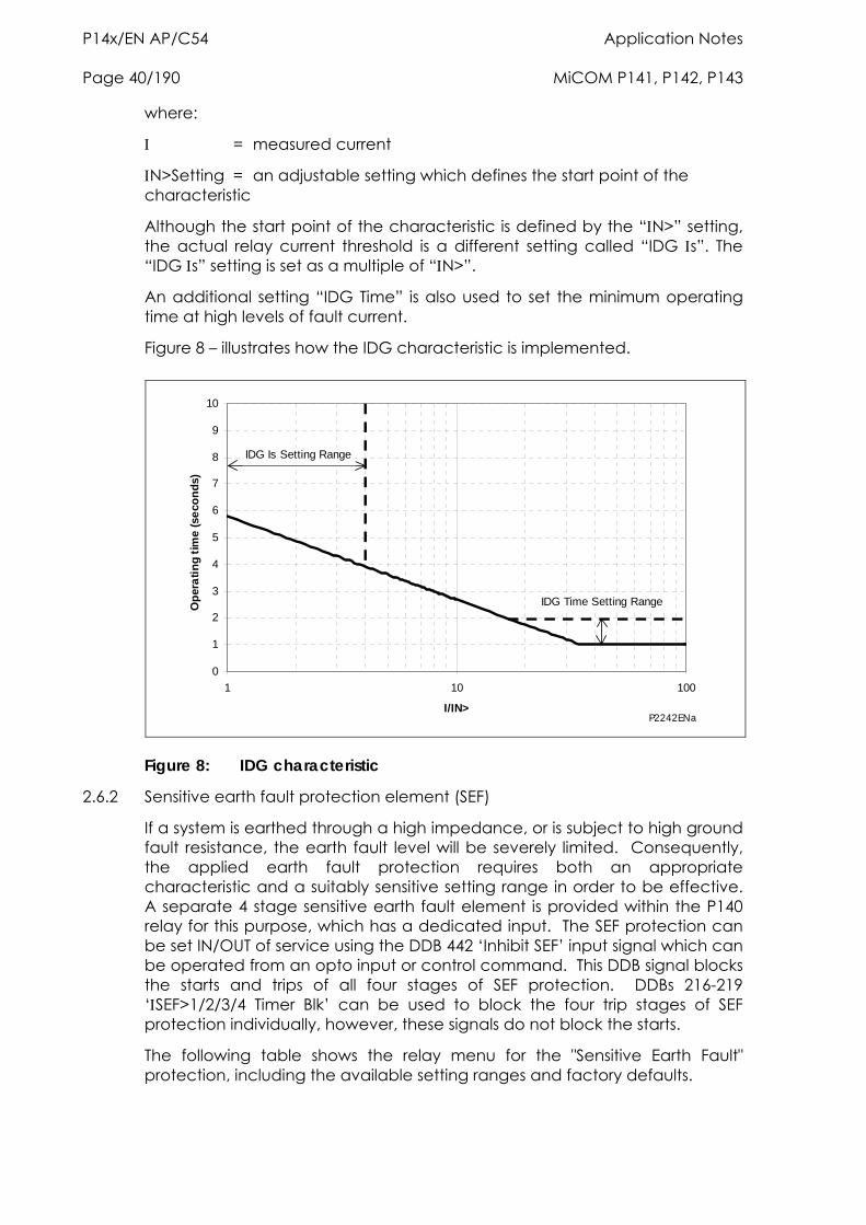
P14x/EN AP/C54 Application Notes Page 40/190 MiCOM P141, P142, P143
where:
= measured current
N>Setting = an adjustable setting which defines the start point of the characteristic
Although the start point of the characteristic is defined by the “N>” setting, the actual relay current threshold is a different setting called “IDG s”. The “IDG s” setting is set as a multiple of “N>”.
An additional setting “IDG Time” is also used to set the minimum operating time at high levels of fault current.
Figure 8 – illustrates how the IDG characteristic is implemented.
0
1
2
3
4
5
6
7
8
9
10
1 10 100
I/IN>
Op
era
tin
g t
ime
(se
con
ds)
IDG Is Setting Range
IDG Time Setting Range
P2242ENa
Figure 8: IDG characteristic
2.6.2 Sensitive earth fault protection element (SEF)
If a system is earthed through a high impedance, or is subject to high ground fault resistance, the earth fault level will be severely limited. Consequently, the applied earth fault protection requires both an appropriate characteristic and a suitably sensitive setting range in order to be effective. A separate 4 stage sensitive earth fault element is provided within the P140 relay for this purpose, which has a dedicated input. The SEF protection can be set IN/OUT of service using the DDB 442 ‘Inhibit SEF’ input signal which can be operated from an opto input or control command. This DDB signal blocks the starts and trips of all four stages of SEF protection. DDBs 216-219 ‘SEF>1/2/3/4 Timer Blk’ can be used to block the four trip stages of SEF protection individually, however, these signals do not block the starts.
The following table shows the relay menu for the "Sensitive Earth Fault" protection, including the available setting ranges and factory defaults.
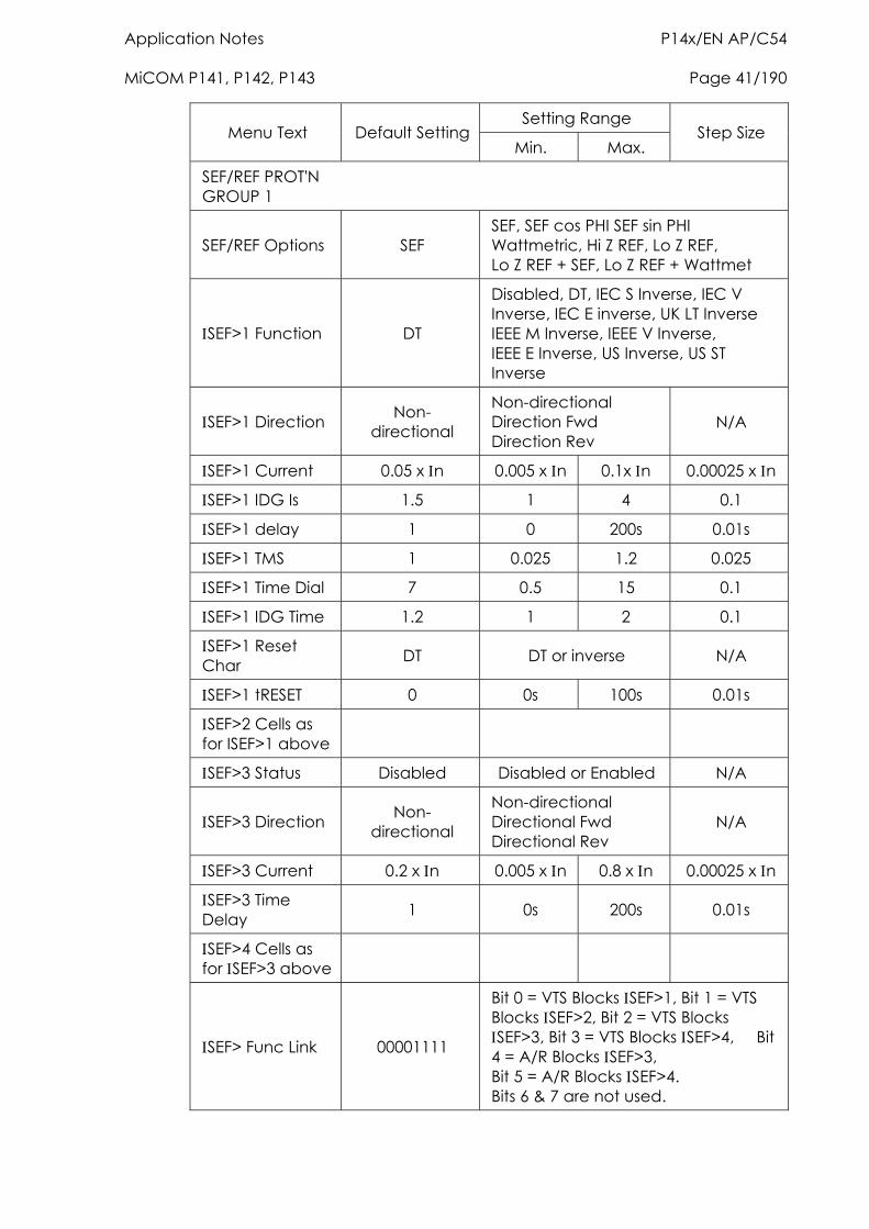
Application Notes P14x/EN AP/C54 MiCOM P141, P142, P143 Page 41/190
Setting Range Menu Text Default Setting
Min. Max. Step Size
SEF/REF PROT'N GROUP 1
SEF/REF Options SEF SEF, SEF cos PHI SEF sin PHI Wattmetric, Hi Z REF, Lo Z REF, Lo Z REF + SEF, Lo Z REF + Wattmet
SEF>1 Function DT
Disabled, DT, IEC S Inverse, IEC V Inverse, IEC E inverse, UK LT Inverse IEEE M Inverse, IEEE V Inverse, IEEE E Inverse, US Inverse, US ST Inverse
SEF>1 Direction Non-directional
Non-directional Direction Fwd Direction Rev
N/A
SEF>1 Current 0.05 x n 0.005 x n 0.1x n 0.00025 x n
SEF>1 IDG Is 1.5 1 4 0.1
SEF>1 delay 1 0 200s 0.01s
SEF>1 TMS 1 0.025 1.2 0.025
SEF>1 Time Dial 7 0.5 15 0.1
SEF>1 IDG Time 1.2 1 2 0.1
SEF>1 Reset Char DT DT or inverse N/A
SEF>1 tRESET 0 0s 100s 0.01s
SEF>2 Cells as for ISEF>1 above
SEF>3 Status Disabled Disabled or Enabled N/A
SEF>3 Direction Non-directional
Non-directional Directional Fwd Directional Rev
N/A
SEF>3 Current 0.2 x n 0.005 x n 0.8 x n 0.00025 x n
SEF>3 Time Delay 1 0s 200s 0.01s
SEF>4 Cells as for SEF>3 above
SEF> Func Link 00001111
Bit 0 = VTS Blocks SEF>1, Bit 1 = VTS Blocks SEF>2, Bit 2 = VTS Blocks SEF>3, Bit 3 = VTS Blocks SEF>4, Bit 4 = A/R Blocks SEF>3, Bit 5 = A/R Blocks SEF>4. Bits 6 & 7 are not used.
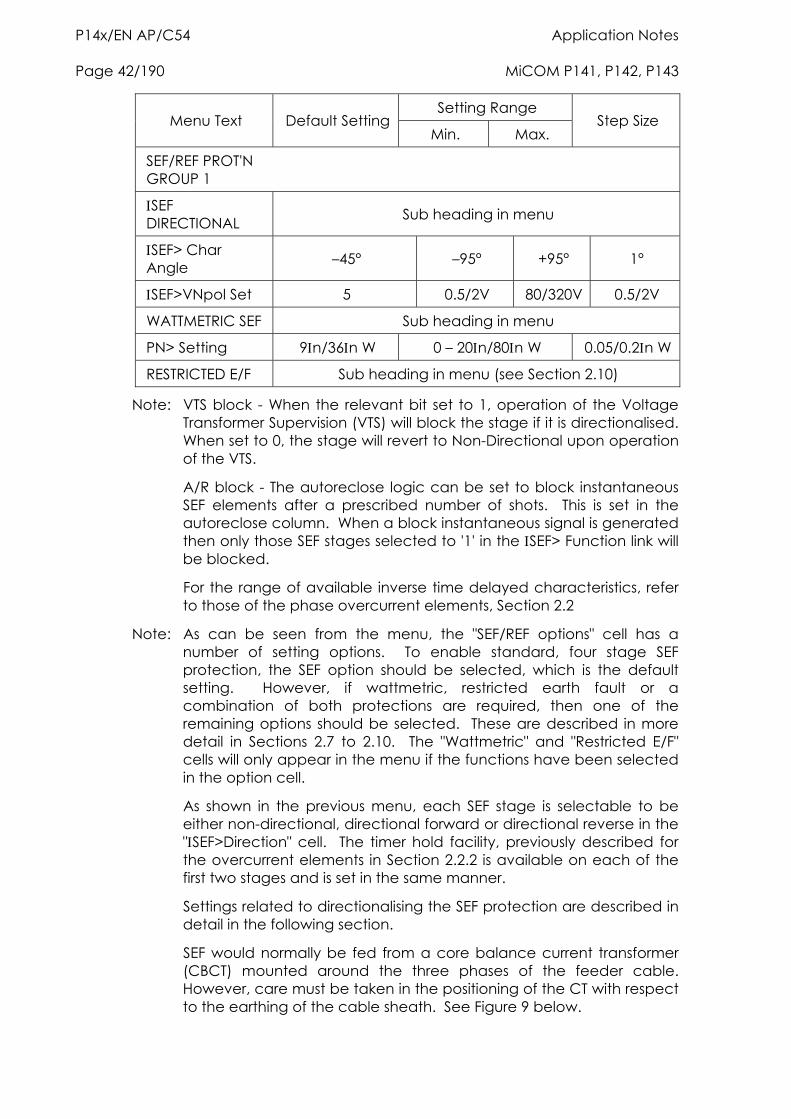
P14x/EN AP/C54 Application Notes Page 42/190 MiCOM P141, P142, P143
Setting Range Menu Text Default Setting
Min. Max. Step Size
SEF/REF PROT'N GROUP 1
SEF DIRECTIONAL Sub heading in menu
SEF> Char Angle –45° –95° +95° 1°
SEF>VNpol Set 5 0.5/2V 80/320V 0.5/2V
WATTMETRIC SEF Sub heading in menu
PN> Setting 9n/36n W 0 – 20n/80n W 0.05/0.2n W
RESTRICTED E/F Sub heading in menu (see Section 2.10)
Note: VTS block - When the relevant bit set to 1, operation of the Voltage Transformer Supervision (VTS) will block the stage if it is directionalised. When set to 0, the stage will revert to Non-Directional upon operation of the VTS.
A/R block - The autoreclose logic can be set to block instantaneous SEF elements after a prescribed number of shots. This is set in the autoreclose column. When a block instantaneous signal is generated then only those SEF stages selected to '1' in the SEF> Function link will be blocked.
For the range of available inverse time delayed characteristics, refer to those of the phase overcurrent elements, Section 2.2
Note: As can be seen from the menu, the "SEF/REF options" cell has a number of setting options. To enable standard, four stage SEF protection, the SEF option should be selected, which is the default setting. However, if wattmetric, restricted earth fault or a combination of both protections are required, then one of the remaining options should be selected. These are described in more detail in Sections 2.7 to 2.10. The "Wattmetric" and "Restricted E/F" cells will only appear in the menu if the functions have been selected in the option cell.
As shown in the previous menu, each SEF stage is selectable to be either non-directional, directional forward or directional reverse in the "SEF>Direction" cell. The timer hold facility, previously described for the overcurrent elements in Section 2.2.2 is available on each of the first two stages and is set in the same manner.
Settings related to directionalising the SEF protection are described in detail in the following section.
SEF would normally be fed from a core balance current transformer (CBCT) mounted around the three phases of the feeder cable. However, care must be taken in the positioning of the CT with respect to the earthing of the cable sheath. See Figure 9 below.
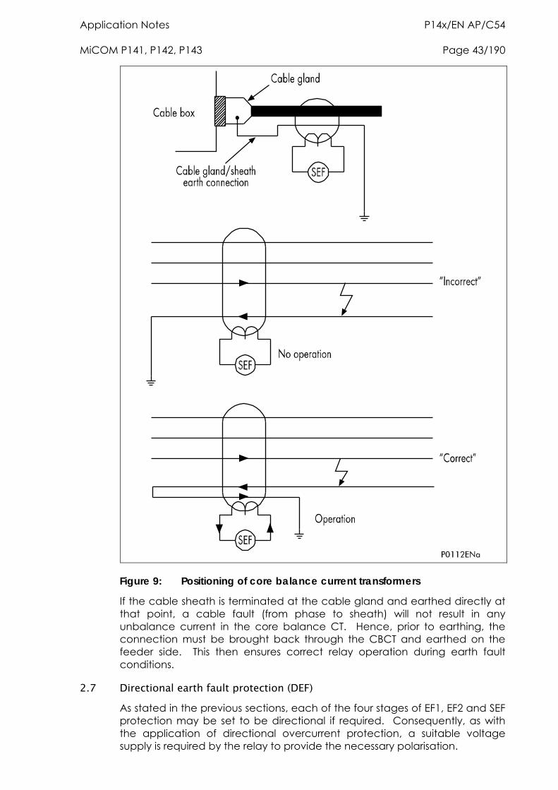
Application Notes P14x/EN AP/C54 MiCOM P141, P142, P143 Page 43/190
Figure 9: Positioning of core balance current transformers
If the cable sheath is terminated at the cable gland and earthed directly at that point, a cable fault (from phase to sheath) will not result in any unbalance current in the core balance CT. Hence, prior to earthing, the connection must be brought back through the CBCT and earthed on the feeder side. This then ensures correct relay operation during earth fault conditions.
2.7 Directional earth fault protection (DEF) As stated in the previous sections, each of the four stages of EF1, EF2 and SEF protection may be set to be directional if required. Consequently, as with the application of directional overcurrent protection, a suitable voltage supply is required by the relay to provide the necessary polarisation.
P14x/EN AP/C54 Application Notes Page 44/190 MiCOM P141, P142, P143
With the standard earth fault protection element in the P140 relay, two options are available for polarisation; Residual Voltage or Negative Sequence.
2.7.1 Residual voltage polarisation
With earth fault protection, the polarising signal requires to be representative of the earth fault condition. As residual voltage is generated during earth fault conditions, this quantity is commonly used to polarise DEF elements. The P140 relay internally derives this voltage from the 3 phase voltage input which must be supplied from either a 5-limb or three single phase VTs. These types of VT design allow the passage of residual flux and consequently permit the relay to derive the required residual voltage. In addition, the primary star point of the VT must be earthed. A three limb VT has no path for residual flux and is therefore unsuitable to supply the relay.
It is possible that small levels of residual voltage will be present under normal system conditions due to system imbalances, VT inaccuracies, relay tolerances etc. Hence, the P140 relay includes a user settable threshold (N>VNPol set) which must be exceeded in order for the DEF function to be operational. The residual voltage measurement provided in the “Measurements 1” column of the menu may assist in determining the required threshold setting during the commissioning stage, as this will indicate the level of standing residual voltage present.
Note that residual voltage is nominally 180° out of phase with residual current. Consequently, the DEF elements are polarised from the "-Vres" quantity. This 180° phase shift is automatically introduced within the P140 relay.
2.7.2 Negative sequence polarisation
In certain applications, the use of residual voltage polarisation of DEF may either be not possible to achieve, or problematic. An example of the former case would be where a suitable type of VT was unavailable, for example if only a three limb VT was fitted. An example of the latter case would be an HV/EHV parallel line application where problems with zero sequence mutual coupling may exist.
In either of these situations, the problem may be solved by the use of negative phase sequence (nps) quantities for polarisation. This method determines the fault direction by comparison of nps voltage with nps current. The operate quantity, however, is still residual current.
This is available for selection on both the derived and measured standard earth fault elements (EF1 and EF2) but not on the SEF protection. It requires a suitable voltage and current threshold to be set in cells "N>V2pol set" and "N>2pol set", respectively.
Negative sequence polarising is not recommended for impedance earthed systems regardless of the type of VT feeding the relay. This is due to the reduced earth fault current limiting the voltage drop across the negative sequence source impedance (V2pol) to negligible levels. If this voltage is less than 0.5 volts the relay will cease to provide DEF protection.
Application Notes P14x/EN AP/C54 MiCOM P141, P142, P143 Page 45/190
2.7.3 General setting guidelines for DEF
When setting the Relay Characteristic Angle (RCA) for the directional overcurrent element, a positive angle setting was specified. This was due to the fact that the quadrature polarising voltage lagged the nominal phase current by 90°. i.e. the position of the current under fault conditions was leading the polarising voltage and hence a positive RCA was required. With DEF, the residual current under fault conditions lies at an angle lagging the polarising voltage. Hence, negative RCA settings are required for DEF applications. This is set in cell ">Char Angle" in the relevant earth fault menu.
The following angle settings are recommended for a residual voltage polarised relay:
Resistance earthed systems = 0°
Distribution systems (solidly earthed) = –45°
Transmission Systems (solidly earthed) = –60°
For negative sequence polarisation, the RCA settings must be based on the angle of the nps source impedance, much the same as for residual polarising. Typical settings would be:
Distribution systems –45°
Transmission Systems –60°
2.7.4 Application to insulated systems
The advantage gained by running a power system which is insulated from earth is the fact that during a single phase to earth fault condition, no earth fault current is allowed to flow. Consequently, it is possible to maintain power flow on the system even when an earth fault condition is present. However, this advantage is offset by the fact that the resultant steady state and transient overvoltages on the sound phases can be very high. It is generally the case, therefore, that insulated systems will only be used in low/medium voltage networks where it does not prove too costly to provide the necessary insulation against such overvoltages. Higher system voltages would normally be solidly earthed or earthed via a low impedance.
Operational advantages may be gained by the use of insulated systems. However, it is still vital that detection of the fault is achieved. This is not possible by means of standard current operated earth fault protection. One possibility for fault detection is by means of a residual overvoltage device. This functionality is included within the P140 relays and is detailed in Section 2.11. However, fully discriminative earth fault protection on this type of system can only be achieved by the application of a sensitive earth fault element. This type of relay is set to detect the resultant imbalance in the system charging currents that occurs under earth fault conditions. It is therefore essential that a core balance CT is used for this application.
This eliminates the possibility of spill current that may arise from slight mismatches between residually connected line CTs. It also enables a much lower CT ratio to be applied, thereby allowing the required protection sensitivity to be more easily achieved.
From Figure 10, it can be seen that the relays on the healthy feeders see the unbalance in the charging currents for their own feeder. The relay on the
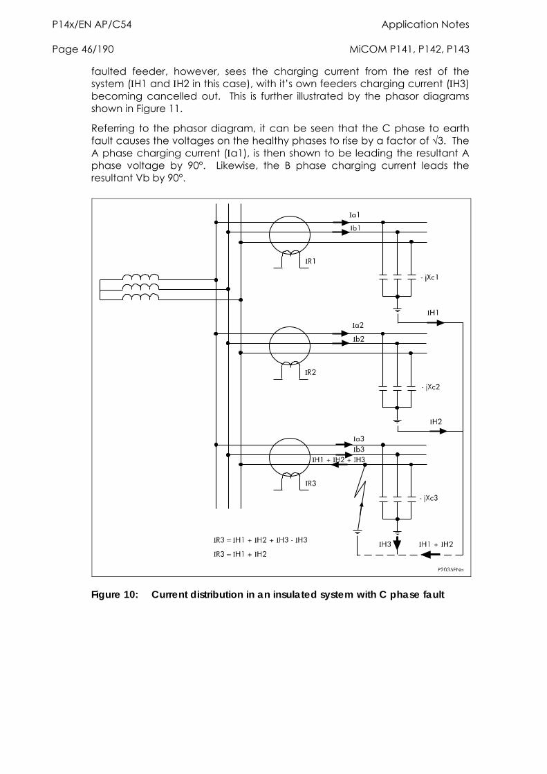
P14x/EN AP/C54 Application Notes Page 46/190 MiCOM P141, P142, P143
faulted feeder, however, sees the charging current from the rest of the system (H1 and H2 in this case), with it’s own feeders charging current (H3) becoming cancelled out. This is further illustrated by the phasor diagrams shown in Figure 11.
Referring to the phasor diagram, it can be seen that the C phase to earth fault causes the voltages on the healthy phases to rise by a factor of √3. The A phase charging current (a1), is then shown to be leading the resultant A phase voltage by 90°. Likewise, the B phase charging current leads the resultant Vb by 90°.
Figure 10: Current distribution in an insulated system with C phase fault
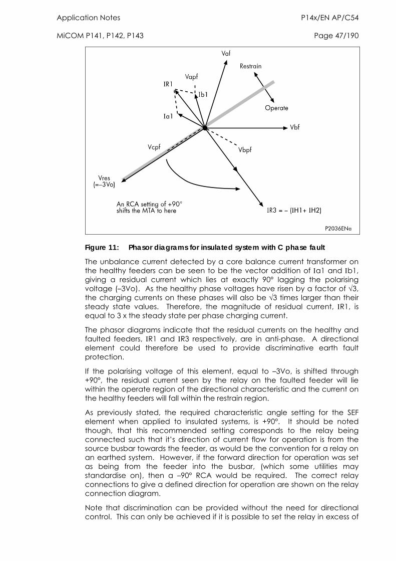
Application Notes P14x/EN AP/C54 MiCOM P141, P142, P143 Page 47/190
Figure 11: Phasor diagrams for insulated system with C phase fault
The unbalance current detected by a core balance current transformer on the healthy feeders can be seen to be the vector addition of a1 and b1, giving a residual current which lies at exactly 90° lagging the polarising voltage (–3Vo). As the healthy phase voltages have risen by a factor of 3, the charging currents on these phases will also be 3 times larger than their steady state values. Therefore, the magnitude of residual current, R1, is equal to 3 x the steady state per phase charging current.
The phasor diagrams indicate that the residual currents on the healthy and faulted feeders, R1 and R3 respectively, are in anti-phase. A directional element could therefore be used to provide discriminative earth fault protection.
If the polarising voltage of this element, equal to –3Vo, is shifted through +90°, the residual current seen by the relay on the faulted feeder will lie within the operate region of the directional characteristic and the current on the healthy feeders will fall within the restrain region.
As previously stated, the required characteristic angle setting for the SEF element when applied to insulated systems, is +90°. It should be noted though, that this recommended setting corresponds to the relay being connected such that it’s direction of current flow for operation is from the source busbar towards the feeder, as would be the convention for a relay on an earthed system. However, if the forward direction for operation was set as being from the feeder into the busbar, (which some utilities may standardise on), then a –90° RCA would be required. The correct relay connections to give a defined direction for operation are shown on the relay connection diagram.
Note that discrimination can be provided without the need for directional control. This can only be achieved if it is possible to set the relay in excess of
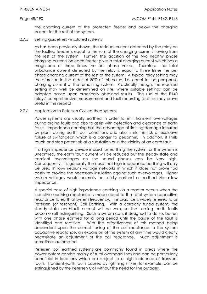
P14x/EN AP/C54 Application Notes Page 48/190 MiCOM P141, P142, P143
the charging current of the protected feeder and below the charging current for the rest of the system.
2.7.5 Setting guidelines - insulated systems
As has been previously shown, the residual current detected by the relay on the faulted feeder is equal to the sum of the charging currents flowing from the rest of the system. Further, the addition of the two healthy phase charging currents on each feeder gives a total charging current which has a magnitude of three times the per phase value. Therefore, the total unbalance current detected by the relay is equal to three times the per phase charging current of the rest of the system. A typical relay setting may therefore be in the order of 30% of this value, i.e. equal to the per phase charging current of the remaining system. Practically though, the required setting may well be determined on site, where suitable settings can be adopted based upon practically obtained results. The use of the P140 relays’ comprehensive measurement and fault recording facilities may prove useful in this respect.
2.7.6 Application to Petersen Coil earthed systems
Power systems are usually earthed in order to limit transient overvoltages during arcing faults and also to assist with detection and clearance of earth faults. Impedance earthing has the advantage of limiting damage incurred by plant during earth fault conditions and also limits the risk of explosive failure of switchgear, which is a danger to personnel. In addition, it limits touch and step potentials at a substation or in the vicinity of an earth fault.
If a high impedance device is used for earthing the system, or the system is unearthed, the earth fault current will be reduced but the steady state and transient overvoltages on the sound phases can be very high. Consequently, it is generally the case that high impedance earthing will only be used in low/medium voltage networks in which it does not prove too costly to provide the necessary insulation against such overvoltages. Higher system voltages would normally be solidly earthed or earthed via a low impedance.
A special case of high impedance earthing via a reactor occurs when the inductive earthing reactance is made equal to the total system capacitive reactance to earth at system frequency. This practice is widely referred to as Petersen (or resonant) Coil Earthing. With a correctly tuned system, the steady state earthfault current will be zero, so that arcing earth faults become self extinguishing. Such a system can, if designed to do so, be run with one phase earthed for a long period until the cause of the fault is identified and rectified. With the effectiveness of this method being dependent upon the correct tuning of the coil reactance to the system capacitive reactance, an expansion of the system at any time would clearly necessitate an adjustment of the coil reactance. Such adjustment is sometimes automated.
Petersen coil earthed systems are commonly found in areas where the power system consists mainly of rural overhead lines and can be particularly beneficial in locations which are subject to a high incidence of transient faults. Transient earth faults caused by lightning strikes, for example, can be extinguished by the Petersen Coil without the need for line outages.
Application Notes P14x/EN AP/C54 MiCOM P141, P142, P143 Page 49/190
Figure 12 shows a source of generation earthed through a Petersen Coil, with an earth fault applied on the A Phase. Under this situation, it can be seen that the A phase shunt capacitance becomes short circuited by the fault. Consequently, the calculations show that if the reactance of the earthing coil is set correctly, the resulting steady state earth fault current will be zero.
Figure 12: Current distribution in Petersen Coil earthed system
Prior to actually applying protective relays to provide earth fault protection on systems which are earthed via a Petersen Coil, it is imperative to gain an understanding of the current distributions that occur under fault conditions on such systems. With this knowledge, it is then possible to decide on the type of relay that may be applied, ensuring that it is both set and connected correctly.
Figure 13 shows a radial distribution system having a source which is earthed via a Petersen Coil. Three outgoing feeders are present, the lower of which has a phase to earth fault applied on the C phase.
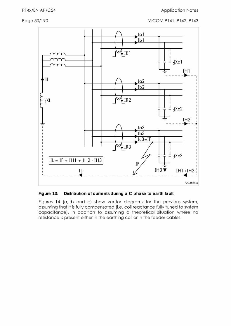
P14x/EN AP/C54 Application Notes Page 50/190 MiCOM P141, P142, P143
Figure 13: Distribution of currents during a C phase to earth fault
Figures 14 (a, b and c) show vector diagrams for the previous system, assuming that it is fully compensated (i.e. coil reactance fully tuned to system capacitance), in addition to assuming a theoretical situation where no resistance is present either in the earthing coil or in the feeder cables.
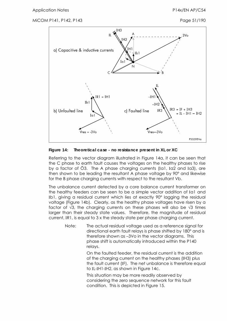
Application Notes P14x/EN AP/C54 MiCOM P141, P142, P143 Page 51/190
Figure 14: Theoretical case - no resistance present in XL or XC
Referring to the vector diagram illustrated in Figure 14a, it can be seen that the C phase to earth fault causes the voltages on the healthy phases to rise by a factor of Ö3. The A phase charging currents (a1, a2 and a3), are then shown to be leading the resultant A phase voltage by 90° and likewise for the B phase charging currents with respect to the resultant Vb.
The unbalance current detected by a core balance current transformer on the healthy feeders can be seen to be a simple vector addition of a1 and b1, giving a residual current which lies at exactly 90° lagging the residual voltage (Figure 14b). Clearly, as the healthy phase voltages have risen by a factor of 3, the charging currents on these phases will also be 3 times larger than their steady state values. Therefore, the magnitude of residual current, R1, is equal to 3 x the steady state per phase charging current.
Note: The actual residual voltage used as a reference signal for directional earth fault relays is phase shifted by 180° and is therefore shown as –3Vo in the vector diagrams. This phase shift is automatically introduced within the P140 relays.
On the faulted feeder, the residual current is the addition of the charging current on the healthy phases (H3) plus the fault current (F). The net unbalance is therefore equal to L-H1-H2, as shown in Figure 14c.
This situation may be more readily observed by considering the zero sequence network for this fault condition. This is depicted in Figure 15.
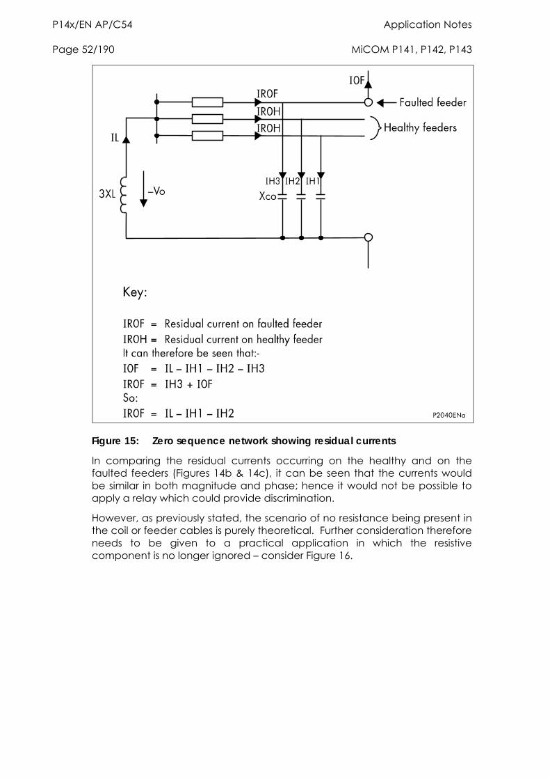
P14x/EN AP/C54 Application Notes Page 52/190 MiCOM P141, P142, P143
Figure 15: Zero sequence network showing residual currents
In comparing the residual currents occurring on the healthy and on the faulted feeders (Figures 14b & 14c), it can be seen that the currents would be similar in both magnitude and phase; hence it would not be possible to apply a relay which could provide discrimination.
However, as previously stated, the scenario of no resistance being present in the coil or feeder cables is purely theoretical. Further consideration therefore needs to be given to a practical application in which the resistive component is no longer ignored – consider Figure 16.
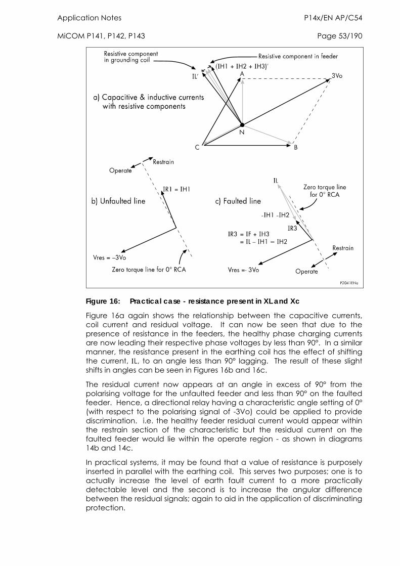
Application Notes P14x/EN AP/C54 MiCOM P141, P142, P143 Page 53/190
Figure 16: Practical case - resistance present in XL and Xc
Figure 16a again shows the relationship between the capacitive currents, coil current and residual voltage. It can now be seen that due to the presence of resistance in the feeders, the healthy phase charging currents are now leading their respective phase voltages by less than 90°. In a similar manner, the resistance present in the earthing coil has the effect of shifting the current, L, to an angle less than 90° lagging. The result of these slight shifts in angles can be seen in Figures 16b and 16c.
The residual current now appears at an angle in excess of 90° from the polarising voltage for the unfaulted feeder and less than 90° on the faulted feeder. Hence, a directional relay having a characteristic angle setting of 0° (with respect to the polarising signal of -3Vo) could be applied to provide discrimination. i.e. the healthy feeder residual current would appear within the restrain section of the characteristic but the residual current on the faulted feeder would lie within the operate region - as shown in diagrams 14b and 14c.
In practical systems, it may be found that a value of resistance is purposely inserted in parallel with the earthing coil. This serves two purposes; one is to actually increase the level of earth fault current to a more practically detectable level and the second is to increase the angular difference between the residual signals; again to aid in the application of discriminating protection.
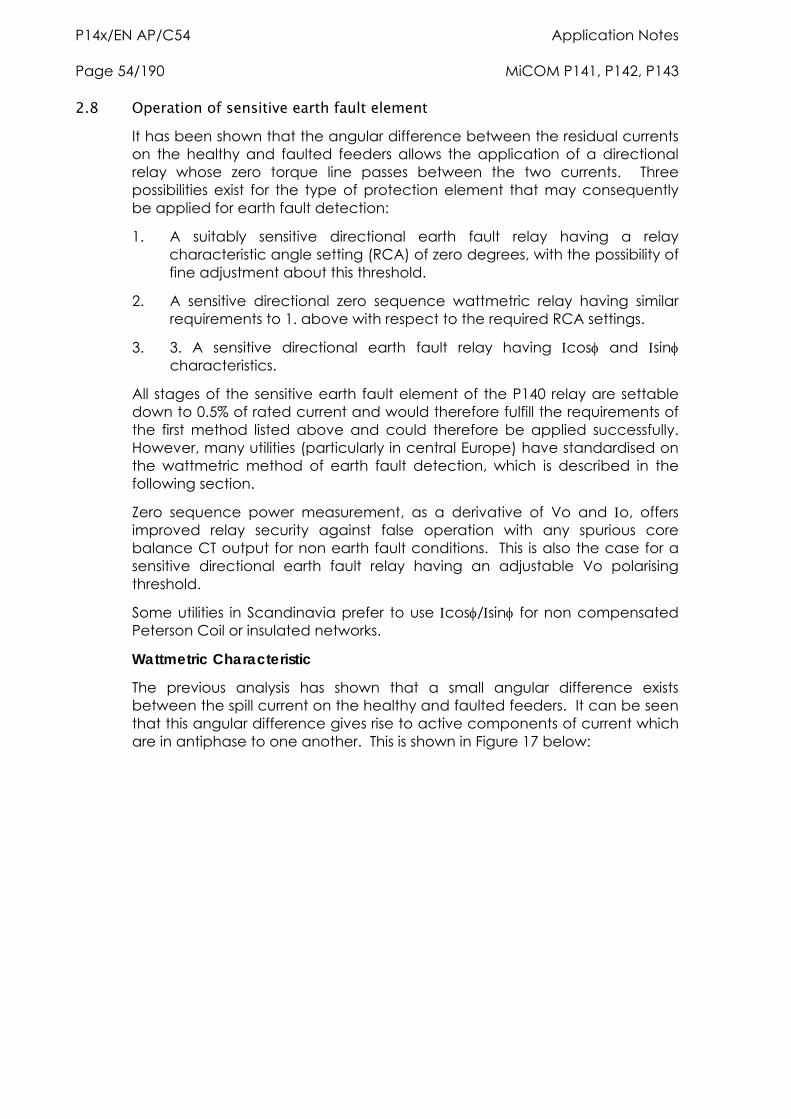
P14x/EN AP/C54 Application Notes Page 54/190 MiCOM P141, P142, P143
2.8 Operation of sensitive earth fault element It has been shown that the angular difference between the residual currents on the healthy and faulted feeders allows the application of a directional relay whose zero torque line passes between the two currents. Three possibilities exist for the type of protection element that may consequently be applied for earth fault detection:
1. A suitably sensitive directional earth fault relay having a relay characteristic angle setting (RCA) of zero degrees, with the possibility of fine adjustment about this threshold.
2. A sensitive directional zero sequence wattmetric relay having similar requirements to 1. above with respect to the required RCA settings.
3. 3. A sensitive directional earth fault relay having cos and sin characteristics.
All stages of the sensitive earth fault element of the P140 relay are settable down to 0.5% of rated current and would therefore fulfill the requirements of the first method listed above and could therefore be applied successfully. However, many utilities (particularly in central Europe) have standardised on the wattmetric method of earth fault detection, which is described in the following section.
Zero sequence power measurement, as a derivative of Vo and o, offers improved relay security against false operation with any spurious core balance CT output for non earth fault conditions. This is also the case for a sensitive directional earth fault relay having an adjustable Vo polarising threshold.
Some utilities in Scandinavia prefer to use cos/sin for non compensated Peterson Coil or insulated networks.
Wattmetric Characteristic
The previous analysis has shown that a small angular difference exists between the spill current on the healthy and faulted feeders. It can be seen that this angular difference gives rise to active components of current which are in antiphase to one another. This is shown in Figure 17 below:
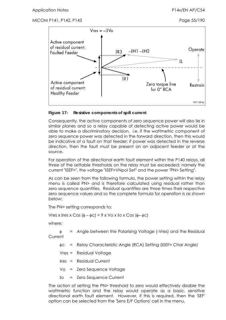
Application Notes P14x/EN AP/C54 MiCOM P141, P142, P143 Page 55/190
Figure 17: Resistive components of spill current
Consequently, the active components of zero sequence power will also lie in similar planes and so a relay capable of detecting active power would be able to make a discriminatory decision. i.e. if the wattmetric component of zero sequence power was detected in the forward direction, then this would be indicative of a fault on that feeder; if power was detected in the reverse direction, then the fault must be present on an adjacent feeder or at the source.
For operation of the directional earth fault element within the P140 relays, all three of the settable thresholds on the relay must be exceeded; namely the current "SEF>", the voltage "SEF>VNpol Set" and the power "PN> Setting".
As can be seen from the following formula, the power setting within the relay menu is called PN> and is therefore calculated using residual rather than zero sequence quantities. Residual quantities are three times their respective zero sequence values and so the complete formula for operation is as shown below:
The PN> setting corresponds to:
Vres x res x Cos ( – c) = 9 x Vo x o x Cos (– c)
where;
= Angle between the Polarising Voltage (-Vres) and the Residual Current
c = Relay Characteristic Angle (RCA) Setting (SEF> Char Angle)
Vres = Residual Voltage
res = Residual Current
Vo = Zero Sequence Voltage
o = Zero Sequence Current
The action of setting the PN> threshold to zero would effectively disable the wattmetric function and the relay would operate as a basic, sensitive directional earth fault element. However, if this is required, then the 'SEF' option can be selected from the 'Sens E/F Options' cell in the menu.
P14x/EN AP/C54 Application Notes Page 56/190 MiCOM P141, P142, P143
A further point to note is that when a power threshold other than zero is selected, a slight alteration is made to the angular boundaries of the directional characteristic. Rather than being ±90° from the RCA, they are made slightly narrower at ±85°.
cos /sin Characteristic
In some applications, the residual current on the healthy feeder can lie just inside the operating boundary following a fault condition. The residual current for the faulted feeder lies close to the operating boundary.
In this case, correct discrimination is achieved by means of an cos characteristic as the faulted feeder will have a large active component of residual current, whilst the healthy feeder will have a small value.
For insulated earth applications, it is common to use the sin characteristic.
2.9 Application considerations Required relay current and voltage connections
Referring to the relevant application diagram for the P140 Relay, it should be applied such that it’s direction for forward operation is looking down into the protected feeder (away from the busbar), with a 0° RCA setting.
As illustrated in the relay application diagram, it is usual for the earth fault element to be driven from a core balance current transformer (CBCT). This eliminates the possibility of spill current that may arise from slight mismatches between residually connected line CT’s. It also enables a much lower CT ratio to be applied, thereby allowing the required protection sensitivity to be more easily achieved.
2.9.1 Calculation of required relay settings
As has been previously shown, for a fully compensated system, the residual current detected by the relay on the faulted feeder is equal to the coil current minus the sum of the charging currents flowing from the rest of the system. Further, as stated in the previous section, the addition of the two healthy phase charging currents on each feeder gives a total charging current which has a magnitude of three times the steady state per phase value. Therefore, for a fully compensated system, the total unbalance current detected by the relay is equal to three times the per phase charging current of the faulted circuit. A typical relay setting may therefore be in the order of 30% of this value, i.e. equal to the per phase charging current of the faulted circuit. Practically though, the required setting may well be determined on site, where system faults can be applied and suitable settings can be adopted based upon practically obtained results.
Also, it should be noted that in most situations, the system will not be fully compensated and consequently a small level of steady state fault current will be allowed to flow. The residual current seen by the relay on the faulted feeder may thus be a larger value, which further emphasises the fact that relay settings should be based upon practical current levels, wherever possible.
The above also holds true regarding the required Relay Characteristic Angle (RCA) setting. As has been shown earlier, a nominal RCA setting of 0º is required. However, fine tuning of this setting will require to be carried out on site in order to obtain the optimum setting in accordance with the levels of
Application Notes P14x/EN AP/C54 MiCOM P141, P142, P143 Page 57/190
coil and feeder resistances present. The loading and performance of the CT will also have an effect in this regard. The effect of CT magnetising current will be to create phase lead of current. Whilst this would assist with operation of faulted feeder relays it would reduce the stability margin of healthy feeder relays. A compromise can therefore be reached through fine adjustment of the RCA. This is adjustable in 1° steps on the P140 relays.
2.9.2 Application of settings to the relay
All of the relevant settings can be found under the SENSITIVE E/F column within the relay menu. Within the Sens E/F Options cell, there are two possibilities for selecting wattmetric earth fault protection; either on it’s own or in conjunction with low impedance REF protection, which is described in Section 2.10. The SEF cos and SEF sin options are not available with low impedance REF protection.
Note that the residual power setting, PN>, is scaled by the programmed CT and VT ratios in the relay.
2.10 Restricted earth fault protection Earth faults occurring on a transformer winding or terminal may be of limited magnitude, either due to the impedance present in the earth path or by the percentage of transformer winding that is involved in the fault. As stated in Section 2.6, it is common to apply standby earth fault protection fed from a single CT in the transformer earth connection - this provides time delayed protection for a transformer winding or terminal fault. In general, particularly as the size of the transformer increases, it becomes unacceptable to rely on time delayed protection to clear winding or terminal faults as this would lead to an increased amount of damage to the transformer. A common requirement is therefore to provide instantaneous phase and earth fault protection. These requirements may be fulfilled by applying differential protection across the transformer. However, an earth fault occurring on the LV winding, particularly if it is of a limited level, may not be detected by the differential relay, as it is only measuring the corresponding HV current. Therefore, instantaneous protection which is restricted to operating for transformer earth faults only, is applied. This is referred to as restricted, or balanced, earthfault protection (REF or BEF). The BEF terminology is usually used when the protection is applied to a delta winding.
When applying differential protection such as REF, some suitable means must be employed to give the protection stability under external fault conditions, thus ensuring that relay operation only occurs for faults on the transformer winding / connections.
Two methods are commonly used; bias or high impedance. The biasing technique operates by measuring the level of through current flowing and altering the relay sensitivity accordingly. The high impedance technique ensures that the relay circuit is of sufficiently high impedance such that the differential voltage that may occur under external fault conditions is less than that required to drive setting current through the relay.
The REF protection in the P140 relays may be configured to operate as either a high impedance or biased element and the following sections describe the application of the relay in each mode.
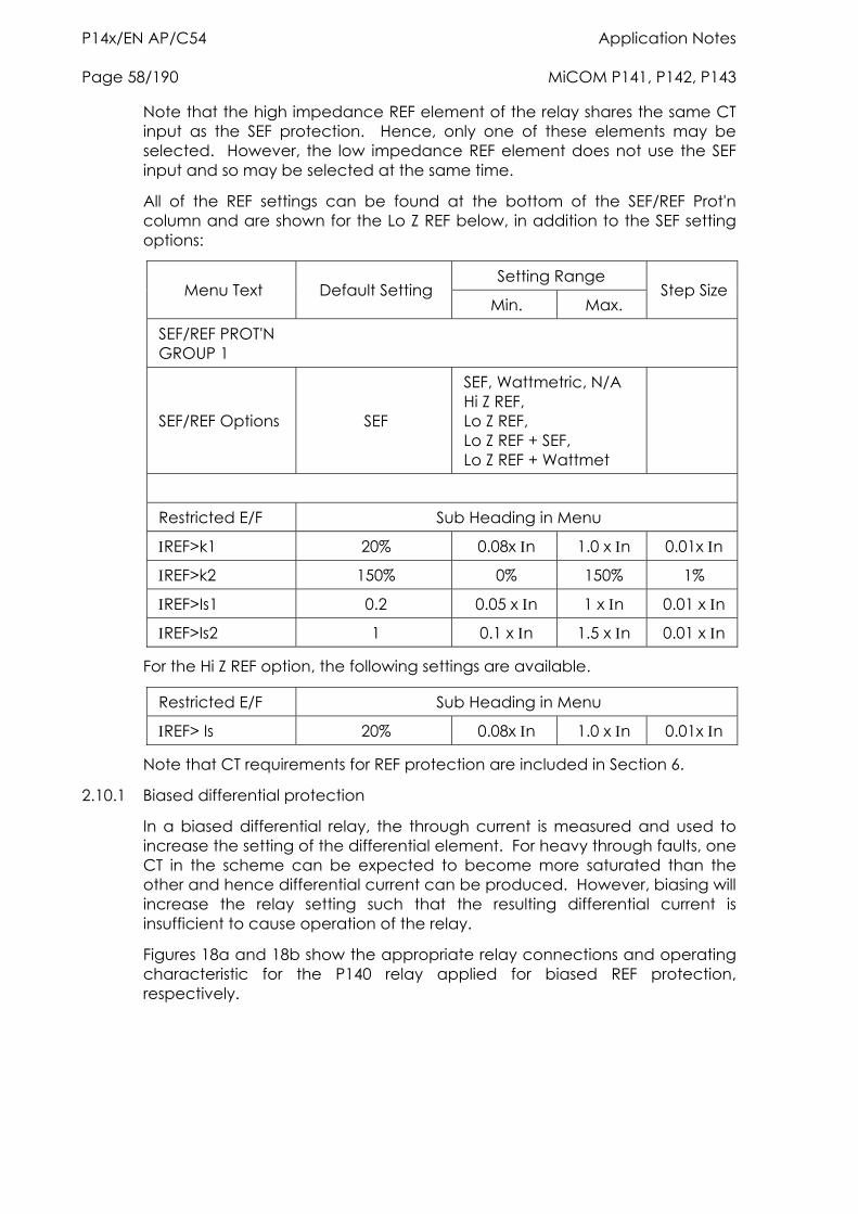
P14x/EN AP/C54 Application Notes Page 58/190 MiCOM P141, P142, P143
Note that the high impedance REF element of the relay shares the same CT input as the SEF protection. Hence, only one of these elements may be selected. However, the low impedance REF element does not use the SEF input and so may be selected at the same time.
All of the REF settings can be found at the bottom of the SEF/REF Prot'n column and are shown for the Lo Z REF below, in addition to the SEF setting options:
Setting Range Menu Text Default Setting
Min. Max. Step Size
SEF/REF PROT'N GROUP 1
SEF/REF Options SEF
SEF, Wattmetric, N/A Hi Z REF, Lo Z REF, Lo Z REF + SEF, Lo Z REF + Wattmet
Restricted E/F Sub Heading in Menu
REF>k1 20% 0.08x n 1.0 x n 0.01x n
REF>k2 150% 0% 150% 1%
REF>Is1 0.2 0.05 x n 1 x n 0.01 x n
REF>Is2 1 0.1 x n 1.5 x n 0.01 x n
For the Hi Z REF option, the following settings are available.
Restricted E/F Sub Heading in Menu
REF> Is 20% 0.08x n 1.0 x n 0.01x n
Note that CT requirements for REF protection are included in Section 6.
2.10.1 Biased differential protection
In a biased differential relay, the through current is measured and used to increase the setting of the differential element. For heavy through faults, one CT in the scheme can be expected to become more saturated than the other and hence differential current can be produced. However, biasing will increase the relay setting such that the resulting differential current is insufficient to cause operation of the relay.
Figures 18a and 18b show the appropriate relay connections and operating characteristic for the P140 relay applied for biased REF protection, respectively.
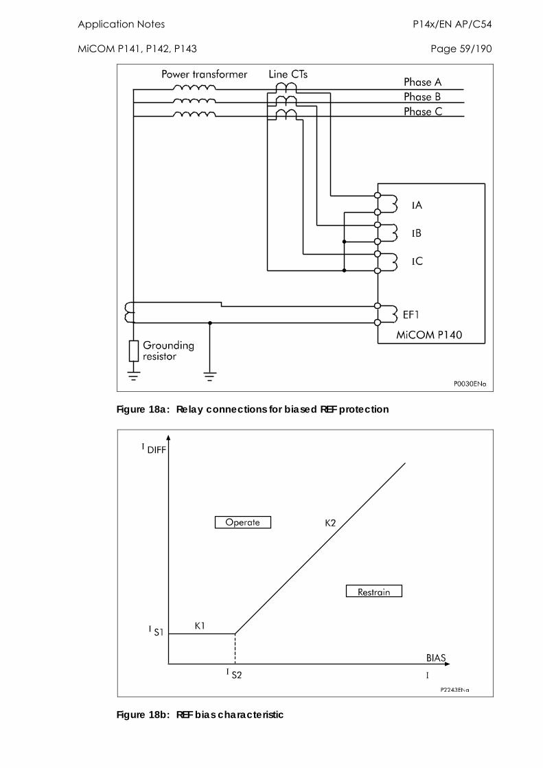
Application Notes P14x/EN AP/C54 MiCOM P141, P142, P143 Page 59/190
Figure 18a: Relay connections for biased REF protection
Figure 18b: REF bias characteristic
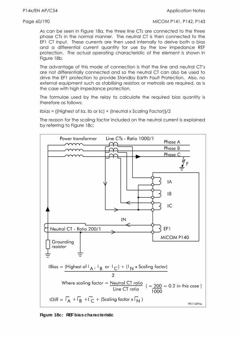
P14x/EN AP/C54 Application Notes Page 60/190 MiCOM P141, P142, P143
As can be seen in Figure 18a, the three line CTs are connected to the three phase CTs in the normal manner. The neutral CT is then connected to the EF1 CT input. These currents are then used internally to derive both a bias and a differential current quantity for use by the low impedance REF protection. The actual operating characteristic of the element is shown in Figure 18b.
The advantage of this mode of connection is that the line and neutral CT’s are not differentially connected and so the neutral CT can also be used to drive the EF1 protection to provide Standby Earth Fault Protection. Also, no external equipment such as stabilising resistors or metrosils are required, as is the case with high impedance protection.
The formulae used by the relay to calculate the required bias quantity is therefore as follows:
bias = {(Highest of a, b or c) + (neutral x Scaling Factor)}/2
The reason for the scaling factor included on the neutral current is explained by referring to Figure 18c:
Figure 18c: REF bias characteristic
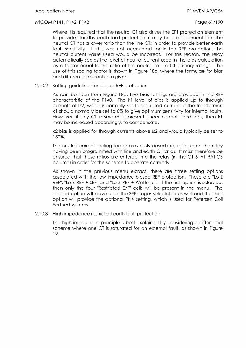
Application Notes P14x/EN AP/C54 MiCOM P141, P142, P143 Page 61/190
Where it is required that the neutral CT also drives the EF1 protection element to provide standby earth fault protection, it may be a requirement that the neutral CT has a lower ratio than the line CTs in order to provide better earth fault sensitivity. If this was not accounted for in the REF protection, the neutral current value used would be incorrect. For this reason, the relay automatically scales the level of neutral current used in the bias calculation by a factor equal to the ratio of the neutral to line CT primary ratings. The use of this scaling factor is shown in Figure 18c, where the formulae for bias and differential currents are given.
2.10.2 Setting guidelines for biased REF protection
As can be seen from Figure 18b, two bias settings are provided in the REF characteristic of the P140. The k1 level of bias is applied up to through currents of s2, which is normally set to the rated current of the transformer. k1 should normally be set to 0% to give optimum sensitivity for internal faults. However, if any CT mismatch is present under normal conditions, then k1 may be increased accordingly, to compensate.
k2 bias is applied for through currents above s2 and would typically be set to 150%.
The neutral current scaling factor previously described, relies upon the relay having been programmed with line and earth CT ratios. It must therefore be ensured that these ratios are entered into the relay (in the CT & VT RATIOS column) in order for the scheme to operate correctly.
As shown in the previous menu extract, there are three setting options associated with the low impedance biased REF protection. These are "Lo Z REF", "Lo Z REF + SEF" and "Lo Z REF + Wattmet". If the first option is selected, then only the four "Restricted E/F" cells will be present in the menu. The second option will leave all of the SEF stages selectable as well and the third option will provide the optional PN> setting, which is used for Petersen Coil Earthed systems.
2.10.3 High impedance restricted earth fault protection
The high impedance principle is best explained by considering a differential scheme where one CT is saturated for an external fault, as shown in Figure 19.
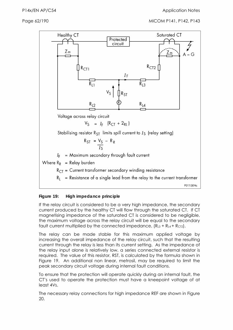
P14x/EN AP/C54 Application Notes Page 62/190 MiCOM P141, P142, P143
Figure 19: High impedance principle
If the relay circuit is considered to be a very high impedance, the secondary current produced by the healthy CT will flow through the saturated CT. If CT magnetising impedance of the saturated CT is considered to be negligible, the maximum voltage across the relay circuit will be equal to the secondary fault current multiplied by the connected impedance, (RL3 + RL4 + RCT2).
The relay can be made stable for this maximum applied voltage by increasing the overall impedance of the relay circuit, such that the resulting current through the relay is less than its current setting. As the impedance of the relay input alone is relatively low, a series connected external resistor is required. The value of this resistor, RST, is calculated by the formula shown in Figure 19. An additional non linear, metrosil, may be required to limit the peak secondary circuit voltage during internal fault conditions.
To ensure that the protection will operate quickly during an internal fault, the CT’s used to operate the protection must have a kneepoint voltage of at least 4Vs.
The necessary relay connections for high impedance REF are shown in Figure 20.
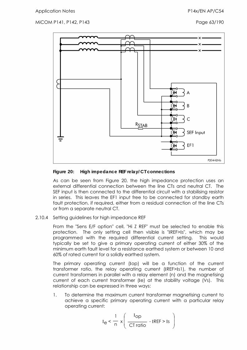
Application Notes P14x/EN AP/C54 MiCOM P141, P142, P143 Page 63/190
Figure 20: High impedance REF relay/CT connections
As can be seen from Figure 20, the high impedance protection uses an external differential connection between the line CTs and neutral CT. The SEF input is then connected to the differential circuit with a stabilising resistor in series. This leaves the EF1 input free to be connected for standby earth fault protection, if required, either from a residual connection of the line CTs or from a separate neutral CT.
2.10.4 Setting guidelines for high impedance REF
From the "Sens E/F option" cell, "Hi Z REF" must be selected to enable this protection. The only setting cell then visible is "REF>s", which may be programmed with the required differential current setting. This would typically be set to give a primary operating current of either 30% of the minimum earth fault level for a resistance earthed system or between 10 and 60% of rated current for a solidly earthed system.
The primary operating current (op) will be a function of the current transformer ratio, the relay operating current (REF>s1), the number of current transformers in parallel with a relay element (n) and the magnetising current of each current transformer (e) at the stability voltage (Vs). This relationship can be expressed in three ways:
1. To determine the maximum current transformer magnetising current to achieve a specific primary operating current with a particular relay operating current:
e < 1
n x
op
CT ratio - REF > s
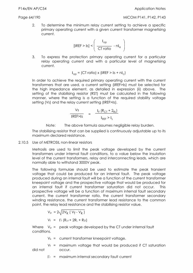
P14x/EN AP/C54 Application Notes Page 64/190 MiCOM P141, P142, P143
2. To determine the minimum relay current setting to achieve a specific primary operating current with a given current transformer magnetising current.
[REF > s] <
op
CT ratio - ne
3. To express the protection primary operating current for a particular relay operating current and with a particular level of magnetising current.
op = (CT ratio) x (REF > s + nc)
In order to achieve the required primary operating current with the current transformers that are used, a current setting (REF>s) must be selected for the high impedance element, as detailed in expression (ii) above. The setting of the stabilising resistor (RST) must be calculated in the following manner, where the setting is a function of the required stability voltage setting (Vs) and the relay current setting (REF>s).
Vs
REF>s = F (RCT + 2RL)
REF > s
Note: The above formula assumes negligible relay burden. The stabilising resistor that can be supplied is continuously adjustable up to its maximum declared resistance.
2.10.5 Use of METROSIL non-linear resistors
Metrosils are used to limit the peak voltage developed by the current transformers under internal fault conditions, to a value below the insulation level of the current transformers, relay and interconnecting leads, which are normally able to withstand 3000V peak.
The following formulae should be used to estimate the peak transient voltage that could be produced for an internal fault. The peak voltage produced during an internal fault will be a function of the current transformer kneepoint voltage and the prospective voltage that would be produced for an internal fault if current transformer saturation did not occur. This prospective voltage will be a function of maximum internal fault secondary current, the current transformer ratio, the current transformer secondary winding resistance, the current transformer lead resistance to the common point, the relay lead resistance and the stabilising resistor value.
Vp = 2 2Vk ( Vf - Vk )
Vf = 'f (Rct + 2RL + RST)
Where Vp = peak voltage developed by the CT under internal fault conditions.
Vk = current transformer kneepoint voltage.
Vf = maximum voltage that would be produced if CT saturation did not occur.
'f = maximum internal secondary fault current
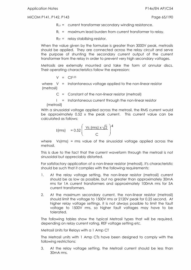
Application Notes P14x/EN AP/C54 MiCOM P141, P142, P143 Page 65/190
Rct = current transformer secondary winding resistance.
RL = maximum lead burden from current transformer to relay.
RST = relay stabilising resistor.
When the value given by the formulae is greater than 3000V peak, metrosils should be applied. They are connected across the relay circuit and serve the purpose of shunting the secondary current output of the current transformer from the relay in order to prevent very high secondary voltages.
Metrosils are externally mounted and take the form of annular discs. Their operating characteristics follow the expression:
V = C0.25
where V = Instantaneous voltage applied to the non-linear resistor (metrosil)
C = Constant of the non-linear resistor (metrosil)
I = Instantaneous current through the non-linear resistor (metrosil)
With a sinusoidal voltage applied across the metrosil, the RMS current would be approximately 0.52 x the peak current. This current value can be calculated as follows:
(rms) = 0.52
Vs (rms) x 2
C 4
where Vs(rms) = rms value of the sinusoidal voltage applied across the metrosil.
This is due to the fact that the current waveform through the metrosil is not sinusoidal but appreciably distorted.
For satisfactory application of a non-linear resistor (metrosil), it's characteristic should be such that it complies with the following requirements:
1. At the relay voltage setting, the non-linear resistor (metrosil) current should be as low as possible, but no greater than approximately 30mA rms for 1A current transformers and approximately 100mA rms for 5A current transformers.
2. At the maximum secondary current, the non-linear resistor (metrosil) should limit the voltage to 1500V rms or 2120V peak for 0.25 second. At higher relay voltage settings, it is not always possible to limit the fault voltage to 1500V rms, so higher fault voltages may have to be tolerated.
The following tables show the typical Metrosil types that will be required, depending on relay current rating, REF voltage setting etc.
Metrosil Units for Relays with a 1 Amp CT
The Metrosil units with 1 Amp CTs have been designed to comply with the following restrictions:
3. At the relay voltage setting, the Metrosil current should be less than 30mA rms.
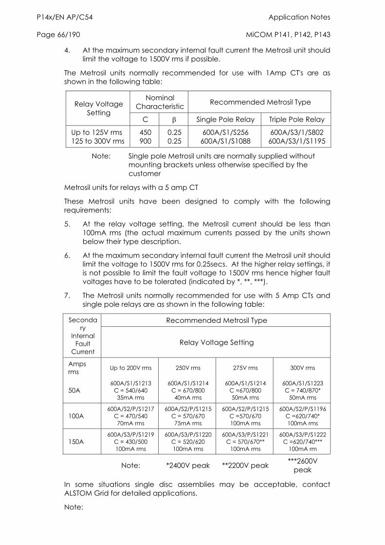
P14x/EN AP/C54 Application Notes Page 66/190 MiCOM P141, P142, P143
4. At the maximum secondary internal fault current the Metrosil unit should limit the voltage to 1500V rms if possible.
The Metrosil units normally recommended for use with 1Amp CT's are as shown in the following table:
Nominal Characteristic Recommended Metrosil Type Relay Voltage
Setting C Single Pole Relay Triple Pole Relay
Up to 125V rms 125 to 300V rms
450 900
0.25 0.25
600A/S1/S256 600A/S1/S1088
600A/S3/1/S802 600A/S3/1/S1195
Note: Single pole Metrosil units are normally supplied without mounting brackets unless otherwise specified by the customer
Metrosil units for relays with a 5 amp CT
These Metrosil units have been designed to comply with the following requirements:
5. At the relay voltage setting, the Metrosil current should be less than 100mA rms (the actual maximum currents passed by the units shown below their type description.
6. At the maximum secondary internal fault current the Metrosil unit should limit the voltage to 1500V rms for 0.25secs. At the higher relay settings, it is not possible to limit the fault voltage to 1500V rms hence higher fault voltages have to be tolerated (indicated by *, **, ***).
7. The Metrosil units normally recommended for use with 5 Amp CTs and single pole relays are as shown in the following table:
Recommended Metrosil Type Secondary
Internal Fault
Current Relay Voltage Setting
Amps rms Up to 200V rms 250V rms 275V rms 300V rms
50A 600A/S1/S1213
C = 540/640 35mA rms
600A/S1/S1214 C = 670/800 40mA rms
600A/S1/S1214 C =670/800 50mA rms
600A/S1/S1223 C = 740/870*
50mA rms
100A 600A/S2/P/S1217
C = 470/540 70mA rms
600A/S2/P/S1215 C = 570/670 75mA rms
600A/S2/P/S1215 C =570/670 100mA rms
600A/S2/P/S1196 C =620/740* 100mA rms
150A 600A/S3/P/S1219
C = 430/500 100mA rms
600A/S3/P/S1220 C = 520/620 100mA rms
600A/S3/P/S1221C = 570/670**
100mA rms
600A/S3/P/S1222C =620/740***
100mA rm
Note: *2400V peak **2200V peak ***2600V
peak
In some situations single disc assemblies may be acceptable, contact ALSTOM Grid for detailed applications.
Note:
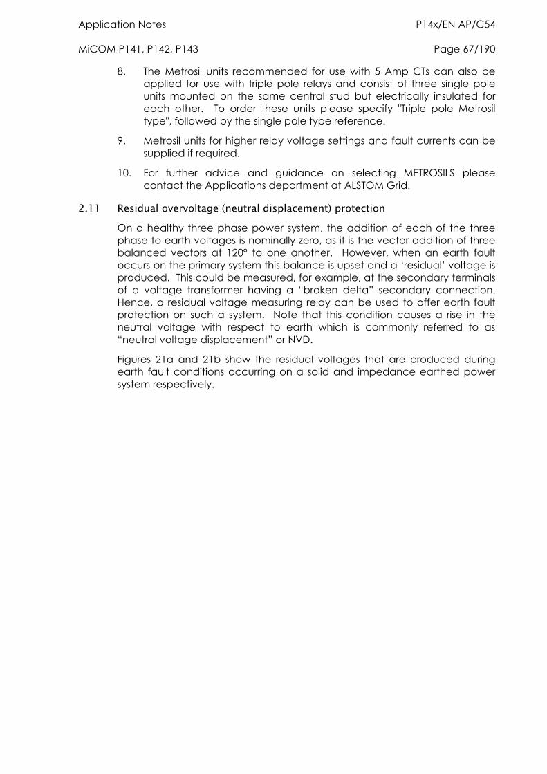
Application Notes P14x/EN AP/C54 MiCOM P141, P142, P143 Page 67/190
8. The Metrosil units recommended for use with 5 Amp CTs can also be applied for use with triple pole relays and consist of three single pole units mounted on the same central stud but electrically insulated for each other. To order these units please specify "Triple pole Metrosil type", followed by the single pole type reference.
9. Metrosil units for higher relay voltage settings and fault currents can be supplied if required.
10. For further advice and guidance on selecting METROSILS please contact the Applications department at ALSTOM Grid.
2.11 Residual overvoltage (neutral displacement) protection On a healthy three phase power system, the addition of each of the three phase to earth voltages is nominally zero, as it is the vector addition of three balanced vectors at 120° to one another. However, when an earth fault occurs on the primary system this balance is upset and a ‘residual’ voltage is produced. This could be measured, for example, at the secondary terminals of a voltage transformer having a “broken delta” secondary connection. Hence, a residual voltage measuring relay can be used to offer earth fault protection on such a system. Note that this condition causes a rise in the neutral voltage with respect to earth which is commonly referred to as “neutral voltage displacement” or NVD.
Figures 21a and 21b show the residual voltages that are produced during earth fault conditions occurring on a solid and impedance earthed power system respectively.
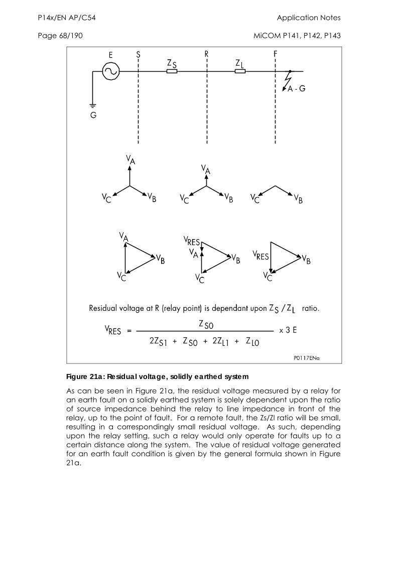
P14x/EN AP/C54 Application Notes Page 68/190 MiCOM P141, P142, P143
Figure 21a: Residual voltage, solidly earthed system
As can be seen in Figure 21a, the residual voltage measured by a relay for an earth fault on a solidly earthed system is solely dependent upon the ratio of source impedance behind the relay to line impedance in front of the relay, up to the point of fault. For a remote fault, the Zs/Zl ratio will be small, resulting in a correspondingly small residual voltage. As such, depending upon the relay setting, such a relay would only operate for faults up to a certain distance along the system. The value of residual voltage generated for an earth fault condition is given by the general formula shown in Figure 21a.
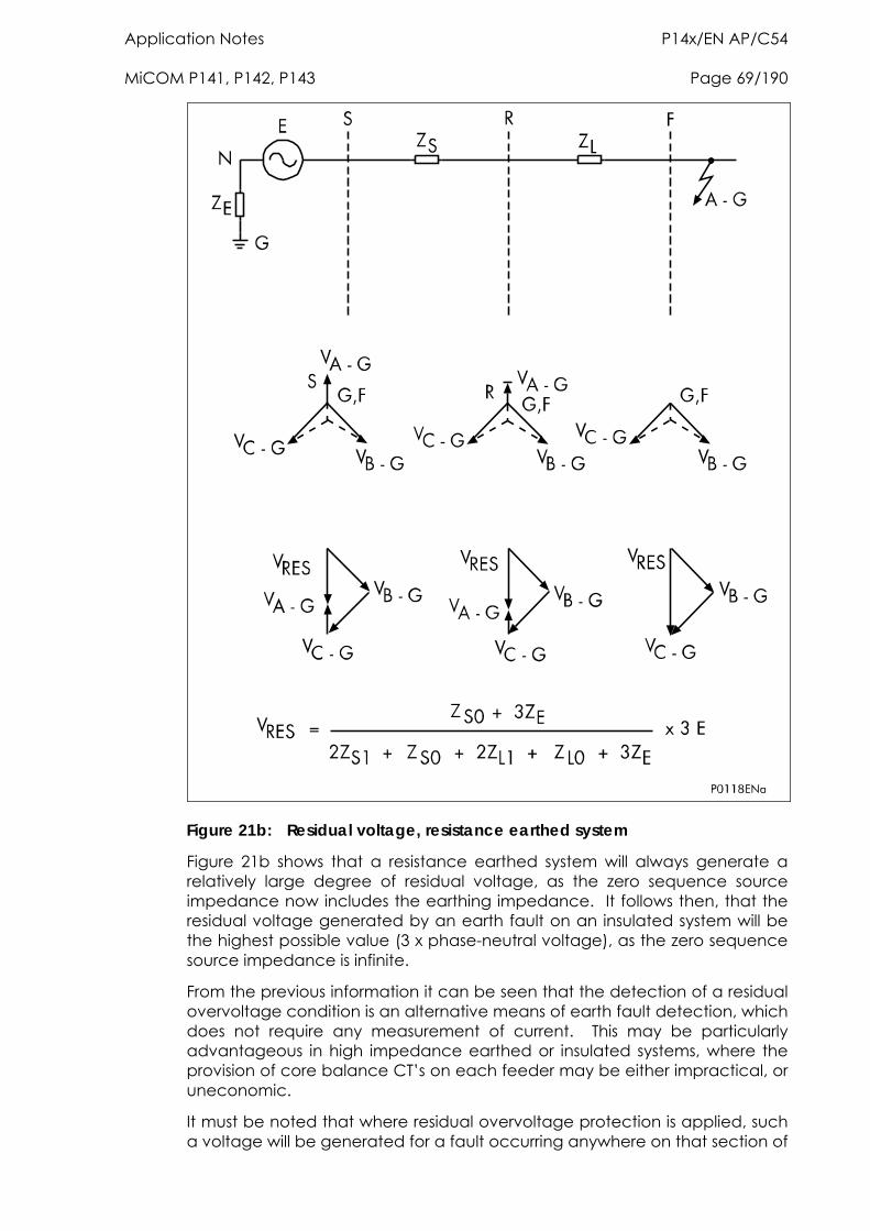
Application Notes P14x/EN AP/C54 MiCOM P141, P142, P143 Page 69/190
Figure 21b: Residual voltage, resistance earthed system
Figure 21b shows that a resistance earthed system will always generate a relatively large degree of residual voltage, as the zero sequence source impedance now includes the earthing impedance. It follows then, that the residual voltage generated by an earth fault on an insulated system will be the highest possible value (3 x phase-neutral voltage), as the zero sequence source impedance is infinite.
From the previous information it can be seen that the detection of a residual overvoltage condition is an alternative means of earth fault detection, which does not require any measurement of current. This may be particularly advantageous in high impedance earthed or insulated systems, where the provision of core balance CT’s on each feeder may be either impractical, or uneconomic.
It must be noted that where residual overvoltage protection is applied, such a voltage will be generated for a fault occurring anywhere on that section of
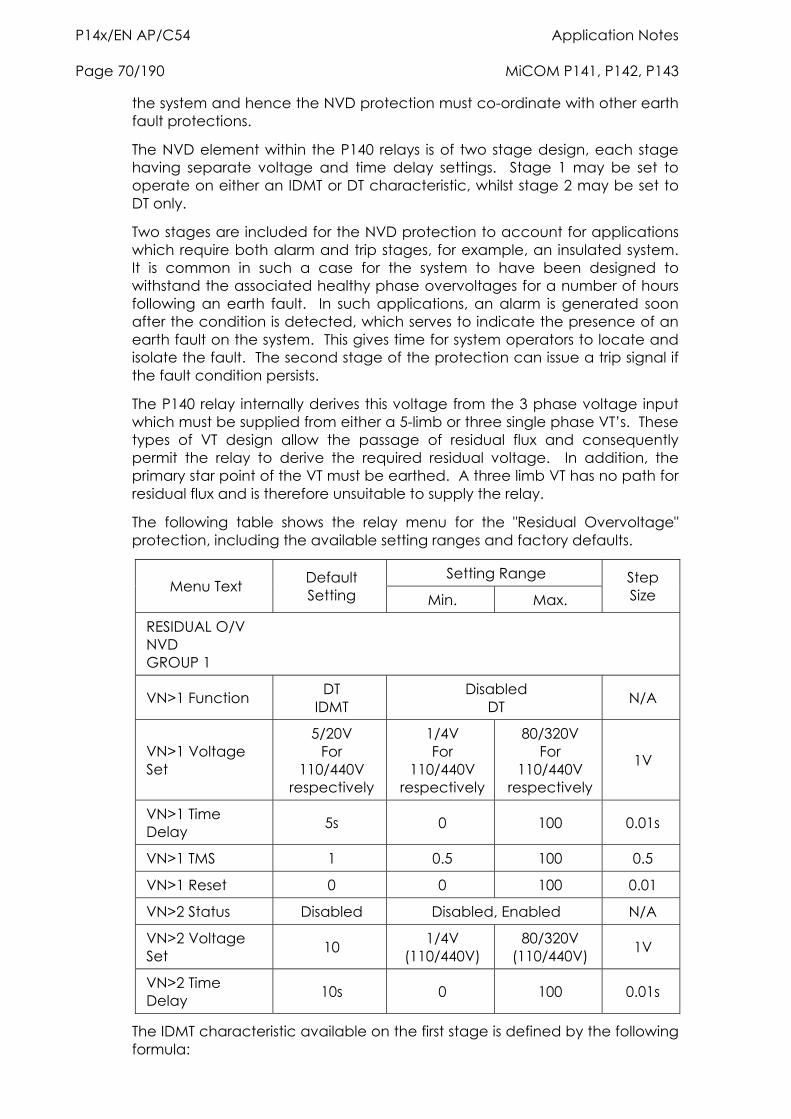
P14x/EN AP/C54 Application Notes Page 70/190 MiCOM P141, P142, P143
the system and hence the NVD protection must co-ordinate with other earth fault protections.
The NVD element within the P140 relays is of two stage design, each stage having separate voltage and time delay settings. Stage 1 may be set to operate on either an IDMT or DT characteristic, whilst stage 2 may be set to DT only.
Two stages are included for the NVD protection to account for applications which require both alarm and trip stages, for example, an insulated system. It is common in such a case for the system to have been designed to withstand the associated healthy phase overvoltages for a number of hours following an earth fault. In such applications, an alarm is generated soon after the condition is detected, which serves to indicate the presence of an earth fault on the system. This gives time for system operators to locate and isolate the fault. The second stage of the protection can issue a trip signal if the fault condition persists.
The P140 relay internally derives this voltage from the 3 phase voltage input which must be supplied from either a 5-limb or three single phase VT’s. These types of VT design allow the passage of residual flux and consequently permit the relay to derive the required residual voltage. In addition, the primary star point of the VT must be earthed. A three limb VT has no path for residual flux and is therefore unsuitable to supply the relay.
The following table shows the relay menu for the "Residual Overvoltage" protection, including the available setting ranges and factory defaults.
Setting Range Menu Text Default
Setting Min. Max. Step Size
RESIDUAL O/V NVD GROUP 1
VN>1 Function DT IDMT
Disabled DT N/A
VN>1 Voltage Set
5/20V For
110/440V respectively
1/4V For
110/440V respectively
80/320V For
110/440V respectively
1V
VN>1 Time Delay 5s 0 100 0.01s
VN>1 TMS 1 0.5 100 0.5
VN>1 Reset 0 0 100 0.01
VN>2 Status Disabled Disabled, Enabled N/A
VN>2 Voltage Set 10 1/4V
(110/440V) 80/320V
(110/440V) 1V
VN>2 Time Delay 10s 0 100 0.01s
The IDMT characteristic available on the first stage is defined by the following formula:
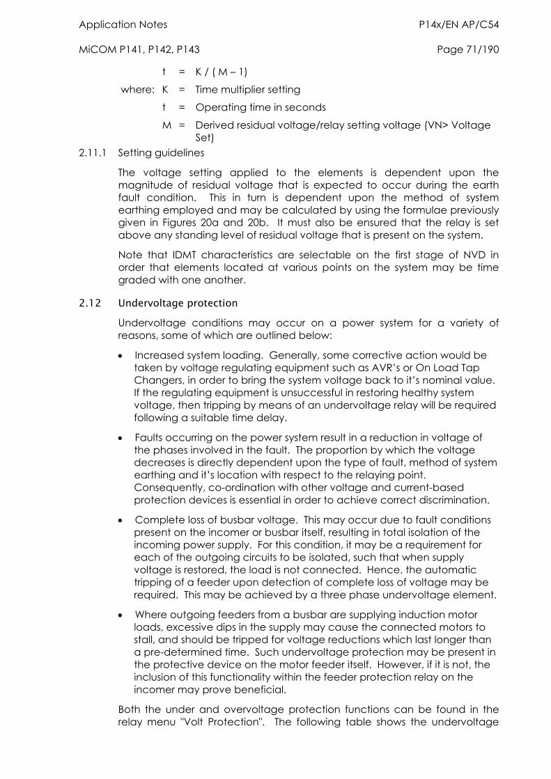
Application Notes P14x/EN AP/C54 MiCOM P141, P142, P143 Page 71/190
t = K / ( M – 1)
where: K = Time multiplier setting
t = Operating time in seconds
M = Derived residual voltage/relay setting voltage (VN> Voltage Set)
2.11.1 Setting guidelines
The voltage setting applied to the elements is dependent upon the magnitude of residual voltage that is expected to occur during the earth fault condition. This in turn is dependent upon the method of system earthing employed and may be calculated by using the formulae previously given in Figures 20a and 20b. It must also be ensured that the relay is set above any standing level of residual voltage that is present on the system.
Note that IDMT characteristics are selectable on the first stage of NVD in order that elements located at various points on the system may be time graded with one another.
2.12 Undervoltage protection Undervoltage conditions may occur on a power system for a variety of reasons, some of which are outlined below:
Increased system loading. Generally, some corrective action would be taken by voltage regulating equipment such as AVR’s or On Load Tap Changers, in order to bring the system voltage back to it’s nominal value. If the regulating equipment is unsuccessful in restoring healthy system voltage, then tripping by means of an undervoltage relay will be required following a suitable time delay.
Faults occurring on the power system result in a reduction in voltage of the phases involved in the fault. The proportion by which the voltage decreases is directly dependent upon the type of fault, method of system earthing and it’s location with respect to the relaying point. Consequently, co-ordination with other voltage and current-based protection devices is essential in order to achieve correct discrimination.
Complete loss of busbar voltage. This may occur due to fault conditions present on the incomer or busbar itself, resulting in total isolation of the incoming power supply. For this condition, it may be a requirement for each of the outgoing circuits to be isolated, such that when supply voltage is restored, the load is not connected. Hence, the automatic tripping of a feeder upon detection of complete loss of voltage may be required. This may be achieved by a three phase undervoltage element.
Where outgoing feeders from a busbar are supplying induction motor loads, excessive dips in the supply may cause the connected motors to stall, and should be tripped for voltage reductions which last longer than a pre-determined time. Such undervoltage protection may be present in the protective device on the motor feeder itself. However, if it is not, the inclusion of this functionality within the feeder protection relay on the incomer may prove beneficial.
Both the under and overvoltage protection functions can be found in the relay menu "Volt Protection". The following table shows the undervoltage
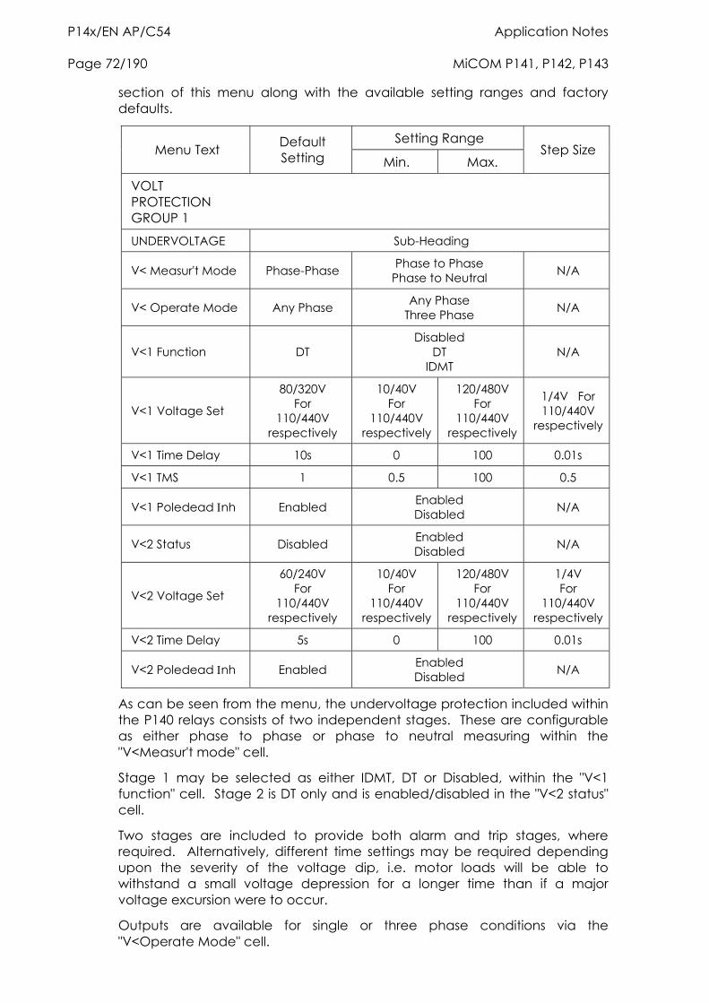
P14x/EN AP/C54 Application Notes Page 72/190 MiCOM P141, P142, P143
section of this menu along with the available setting ranges and factory defaults.
Setting Range Menu Text Default
Setting Min. Max. Step Size
VOLT PROTECTION GROUP 1
UNDERVOLTAGE Sub-Heading
V< Measur't Mode Phase-Phase Phase to Phase Phase to Neutral N/A
V< Operate Mode Any Phase Any Phase Three Phase N/A
V<1 Function DT Disabled
DT IDMT
N/A
V<1 Voltage Set
80/320V For
110/440V respectively
10/40V For
110/440V respectively
120/480V For
110/440V respectively
1/4V For 110/440V
respectively
V<1 Time Delay 10s 0 100 0.01s
V<1 TMS 1 0.5 100 0.5
V<1 Poledead nh Enabled Enabled Disabled N/A
V<2 Status Disabled Enabled Disabled N/A
V<2 Voltage Set
60/240V For
110/440V respectively
10/40V For
110/440V respectively
120/480V For
110/440V respectively
1/4V For
110/440V respectively
V<2 Time Delay 5s 0 100 0.01s
V<2 Poledead nh Enabled Enabled Disabled N/A
As can be seen from the menu, the undervoltage protection included within the P140 relays consists of two independent stages. These are configurable as either phase to phase or phase to neutral measuring within the "V<Measur't mode" cell.
Stage 1 may be selected as either IDMT, DT or Disabled, within the "V<1 function" cell. Stage 2 is DT only and is enabled/disabled in the "V<2 status" cell.
Two stages are included to provide both alarm and trip stages, where required. Alternatively, different time settings may be required depending upon the severity of the voltage dip, i.e. motor loads will be able to withstand a small voltage depression for a longer time than if a major voltage excursion were to occur.
Outputs are available for single or three phase conditions via the "V<Operate Mode" cell.
Application Notes P14x/EN AP/C54 MiCOM P141, P142, P143 Page 73/190
When the protected feeder is de-energised, or the circuit breaker is opened, an undervoltage condition would be detected. Therefore, the "V<Polehead nh" cell is included for each of the two stages to block the undervoltage protection from operating for this condition. If the cell is enabled, the relevant stage will become inhibited by the inbuilt pole dead logic within the relay. This logic produces an output when it detects either an open circuit breaker via auxiliary contacts feeding the relay opto inputs or it detects a combination of both undercurrent and undervoltage on any one phase.
The IDMT characteristic available on the first stage is defined by the following formula:
t = K / (1 - M)
Where:
K = Time multiplier setting
t = Operating time in seconds
M = Measured voltage / relay setting voltage (V< Voltage Set) 2.12.1 Setting guidelines
In the majority of applications, undervoltage protection is not required to operate during system earth fault conditions. If this is the case, the element should be selected in the menu to operate from a phase to phase voltage measurement, as this quantity is less affected by single phase voltage depressions due to earth faults.
The voltage threshold setting for the undervoltage protection should be set at some value below the voltage excursions which may be expected under normal system operating conditions. This threshold is dependent upon the system in question but typical healthy system voltage excursions may be in the order of -10% of nominal value.
Similar comments apply with regard to a time setting for this element, i.e. the required time delay is dependent upon the time for which the system is able to withstand a depressed voltage. As mentioned earlier, if motor loads are connected, then a typical time setting may be in the order of 0.5 seconds.
2.13 Overvoltage protection As previously discussed, undervoltage conditions are relatively common, as they are related to fault conditions etc. However, overvoltage conditions are also a possibility and are generally related to loss of load conditions as described below;
Under conditions of load rejection, the supply voltage will increase in magnitude. This situation would normally be rectified by voltage regulating equipment such as AVR’s or on-load tap changers. However, failure of this equipment to bring the system voltage back within prescribed limits leaves the system with an overvoltage condition which must be cleared in order to preserve the life of the system insulation. Hence, overvoltage protection which is suitably time delayed to allow for normal regulator action, may be applied.
During earth fault conditions on a power system there may be an increase in the healthy phase voltages. Ideally, the system should be designed to withstand such overvoltages for a defined period of time. Normally, there
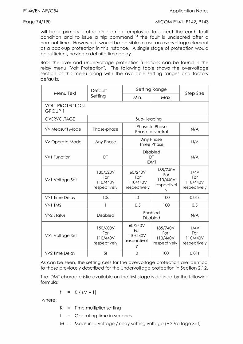
P14x/EN AP/C54 Application Notes Page 74/190 MiCOM P141, P142, P143
will be a primary protection element employed to detect the earth fault condition and to issue a trip command if the fault is uncleared after a nominal time. However, it would be possible to use an overvoltage element as a back-up protection in this instance. A single stage of protection would be sufficient, having a definite time delay.
Both the over and undervoltage protection functions can be found in the relay menu "Volt Protection". The following table shows the overvoltage section of this menu along with the available setting ranges and factory defaults.
Setting Range Menu Text Default
Setting Min. Max. Step Size
VOLT PROTECTION GROUP 1
OVERVOLTAGE Sub-Heading
V> Measur't Mode Phase-phase Phase to Phase Phase to Neutral N/A
V> Operate Mode Any Phase Any Phase Three Phase N/A
V>1 Function DT Disabled
DT IDMT
N/A
V>1 Voltage Set
130/520V For
110/440V respectively
60/240V For
110/440V respectively
185/740V For
110/440V respectivel
y
1/4V For
110/440V respectively
V>1 Time Delay 10s 0 100 0.01s
V>1 TMS 1 0.5 100 0.5
V>2 Status Disabled Enabled Disabled N/A
V>2 Voltage Set
150/600V For
110/440V respectively
60/240V For
110/440V respectivel
y
185/740V For
110/440V respectively
1/4V For
110/440V respectively
V<2 Time Delay 5s 0 100 0.01s
As can be seen, the setting cells for the overvoltage protection are identical to those previously described for the undervoltage protection in Section 2.12.
The IDMT characteristic available on the first stage is defined by the following formula:
t = K / (M – 1)
where:
K = Time multiplier setting
t = Operating time in seconds
M = Measured voltage / relay setting voltage (V> Voltage Set)
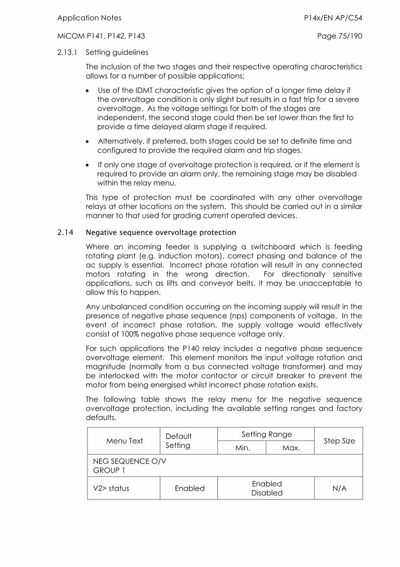
Application Notes P14x/EN AP/C54 MiCOM P141, P142, P143 Page 75/190
2.13.1 Setting guidelines
The inclusion of the two stages and their respective operating characteristics allows for a number of possible applications;
Use of the IDMT characteristic gives the option of a longer time delay if the overvoltage condition is only slight but results in a fast trip for a severe overvoltage. As the voltage settings for both of the stages are independent, the second stage could then be set lower than the first to provide a time delayed alarm stage if required.
Alternatively, if preferred, both stages could be set to definite time and configured to provide the required alarm and trip stages.
If only one stage of overvoltage protection is required, or if the element is required to provide an alarm only, the remaining stage may be disabled within the relay menu.
This type of protection must be coordinated with any other overvoltage relays at other locations on the system. This should be carried out in a similar manner to that used for grading current operated devices.
2.14 Negative sequence overvoltage protection Where an incoming feeder is supplying a switchboard which is feeding rotating plant (e.g. induction motors), correct phasing and balance of the ac supply is essential. Incorrect phase rotation will result in any connected motors rotating in the wrong direction. For directionally sensitive applications, such as lifts and conveyor belts, it may be unacceptable to allow this to happen.
Any unbalanced condition occurring on the incoming supply will result in the presence of negative phase sequence (nps) components of voltage. In the event of incorrect phase rotation, the supply voltage would effectively consist of 100% negative phase sequence voltage only.
For such applications the P140 relay includes a negative phase sequence overvoltage element. This element monitors the input voltage rotation and magnitude (normally from a bus connected voltage transformer) and may be interlocked with the motor contactor or circuit breaker to prevent the motor from being energised whilst incorrect phase rotation exists.
The following table shows the relay menu for the negative sequence overvoltage protection, including the available setting ranges and factory defaults.
Setting Range Menu Text Default
Setting Min. Max. Step Size
NEG SEQUENCE O/V GROUP 1
V2> status Enabled Enabled Disabled N/A
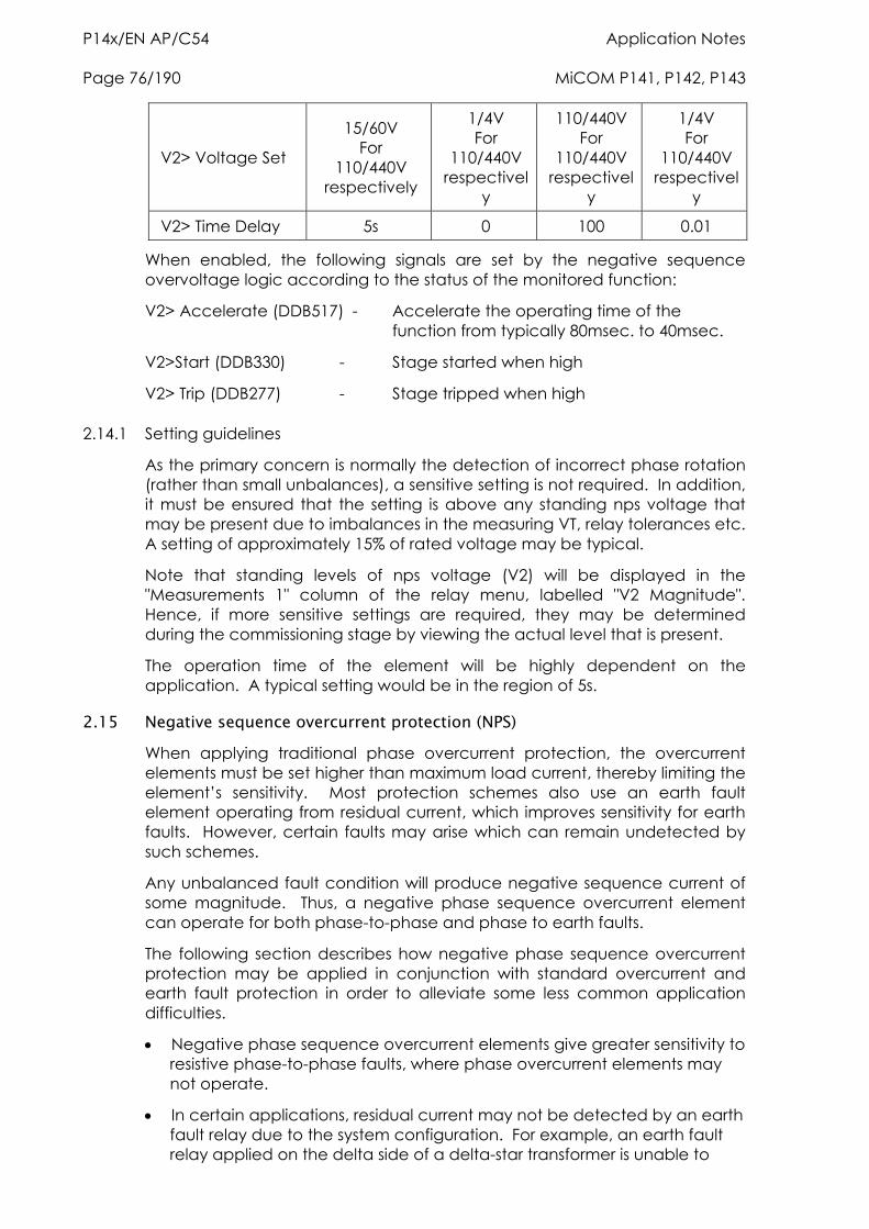
P14x/EN AP/C54 Application Notes Page 76/190 MiCOM P141, P142, P143
V2> Voltage Set
15/60V For
110/440V respectively
1/4V For
110/440V respectivel
y
110/440V For
110/440V respectivel
y
1/4V For
110/440V respectivel
y
V2> Time Delay 5s 0 100 0.01
When enabled, the following signals are set by the negative sequence overvoltage logic according to the status of the monitored function:
V2> Accelerate (DDB517) - Accelerate the operating time of the function from typically 80msec. to 40msec.
V2>Start (DDB330) - Stage started when high
V2> Trip (DDB277) - Stage tripped when high
2.14.1 Setting guidelines
As the primary concern is normally the detection of incorrect phase rotation (rather than small unbalances), a sensitive setting is not required. In addition, it must be ensured that the setting is above any standing nps voltage that may be present due to imbalances in the measuring VT, relay tolerances etc. A setting of approximately 15% of rated voltage may be typical.
Note that standing levels of nps voltage (V2) will be displayed in the "Measurements 1" column of the relay menu, labelled "V2 Magnitude". Hence, if more sensitive settings are required, they may be determined during the commissioning stage by viewing the actual level that is present.
The operation time of the element will be highly dependent on the application. A typical setting would be in the region of 5s.
2.15 Negative sequence overcurrent protection (NPS) When applying traditional phase overcurrent protection, the overcurrent elements must be set higher than maximum load current, thereby limiting the element’s sensitivity. Most protection schemes also use an earth fault element operating from residual current, which improves sensitivity for earth faults. However, certain faults may arise which can remain undetected by such schemes.
Any unbalanced fault condition will produce negative sequence current of some magnitude. Thus, a negative phase sequence overcurrent element can operate for both phase-to-phase and phase to earth faults.
The following section describes how negative phase sequence overcurrent protection may be applied in conjunction with standard overcurrent and earth fault protection in order to alleviate some less common application difficulties.
Negative phase sequence overcurrent elements give greater sensitivity to resistive phase-to-phase faults, where phase overcurrent elements may not operate.
In certain applications, residual current may not be detected by an earth fault relay due to the system configuration. For example, an earth fault relay applied on the delta side of a delta-star transformer is unable to
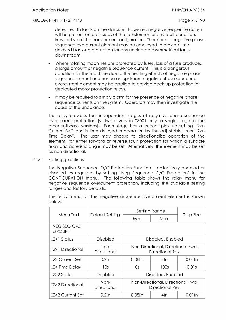
Application Notes P14x/EN AP/C54 MiCOM P141, P142, P143 Page 77/190
detect earth faults on the star side. However, negative sequence current will be present on both sides of the transformer for any fault condition, irrespective of the transformer configuration. Therefore, a negative phase sequence overcurrent element may be employed to provide time-delayed back-up protection for any uncleared asymmetrical faults downstream.
Where rotating machines are protected by fuses, loss of a fuse produces a large amount of negative sequence current. This is a dangerous condition for the machine due to the heating effects of negative phase sequence current and hence an upstream negative phase sequence overcurrent element may be applied to provide back-up protection for dedicated motor protection relays.
It may be required to simply alarm for the presence of negative phase sequence currents on the system. Operators may then investigate the cause of the unbalance.
The relay provides four independent stages of negative phase sequence overcurrent protection [software version 0300J only, a single stage in the other software versions]. Each stage has a current pick up setting "I2>n Current Set", and is time delayed in operation by the adjustable timer "I2>n Time Delay". The user may choose to directionalise operation of the element, for either forward or reverse fault protection for which a suitable relay characteristic angle may be set. Alternatively, the element may be set as non-directional.
2.15.1 Setting guidelines
The Negative Sequence O/C Protection Function is collectively enabled or disabled as required, by setting “Neg Sequence O/C Protection” in the CONFIGURATION menu. The following table shows the relay menu for negative sequence overcurrent protection, including the available setting ranges and factory defaults.
The relay menu for the negative sequence overcurrent element is shown below:
Setting Range Menu Text Default Setting
Min. Max. Step Size
NEG SEQ O/C GROUP 1
2>1 Status Disabled Disabled, Enabled
2>1 Directional Non- Directional
Non-Directional, Directional Fwd, Directional Rev
2> Current Set 0.2n 0.08n 4n 0.01n
2> Time Delay 10s 0s 100s 0.01s
2>2 Status Disabled Disabled, Enabled
2>2 Directional Non- Directional
Non-Directional, Directional Fwd, Directional Rev
2>2 Current Set 0.2n 0.08n 4n 0.01n
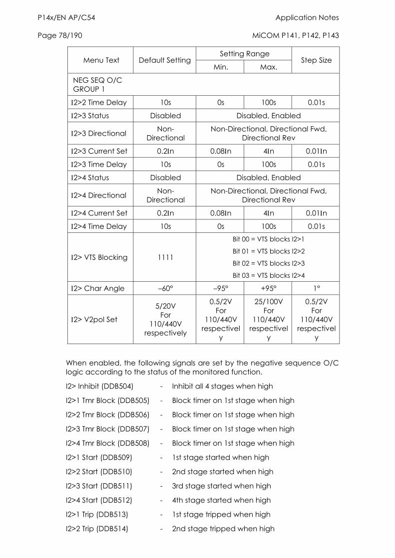
P14x/EN AP/C54 Application Notes Page 78/190 MiCOM P141, P142, P143
Setting Range Menu Text Default Setting
Min. Max. Step Size
NEG SEQ O/C GROUP 1
2>2 Time Delay 10s 0s 100s 0.01s
2>3 Status Disabled Disabled, Enabled
2>3 Directional Non- Directional
Non-Directional, Directional Fwd, Directional Rev
2>3 Current Set 0.2n 0.08n 4n 0.01n
2>3 Time Delay 10s 0s 100s 0.01s
2>4 Status Disabled Disabled, Enabled
2>4 Directional Non- Directional
Non-Directional, Directional Fwd, Directional Rev
2>4 Current Set 0.2n 0.08n 4n 0.01n
2>4 Time Delay 10s 0s 100s 0.01s
2> VTS Blocking 1111
Bit 00 = VTS blocks I2>1
Bit 01 = VTS blocks I2>2
Bit 02 = VTS blocks I2>3
Bit 03 = VTS blocks I2>4
2> Char Angle –60° –95° +95° 1°
2> V2pol Set
5/20V For
110/440V respectively
0.5/2V For
110/440V respectivel
y
25/100V For
110/440V respectivel
y
0.5/2V For
110/440V respectivel
y
When enabled, the following signals are set by the negative sequence O/C logic according to the status of the monitored function.
I2> Inhibit (DDB504) - Inhibit all 4 stages when high
I2>1 Tmr Block (DDB505) - Block timer on 1st stage when high
I2>2 Tmr Block (DDB506) - Block timer on 1st stage when high
I2>3 Tmr Block (DDB507) - Block timer on 1st stage when high
I2>4 Tmr Block (DDB508) - Block timer on 1st stage when high
I2>1 Start (DDB509) - 1st stage started when high
I2>2 Start (DDB510) - 2nd stage started when high
I2>3 Start (DDB511) - 3rd stage started when high
I2>4 Start (DDB512) - 4th stage started when high
I2>1 Trip (DDB513) - 1st stage tripped when high
I2>2 Trip (DDB514) - 2nd stage tripped when high
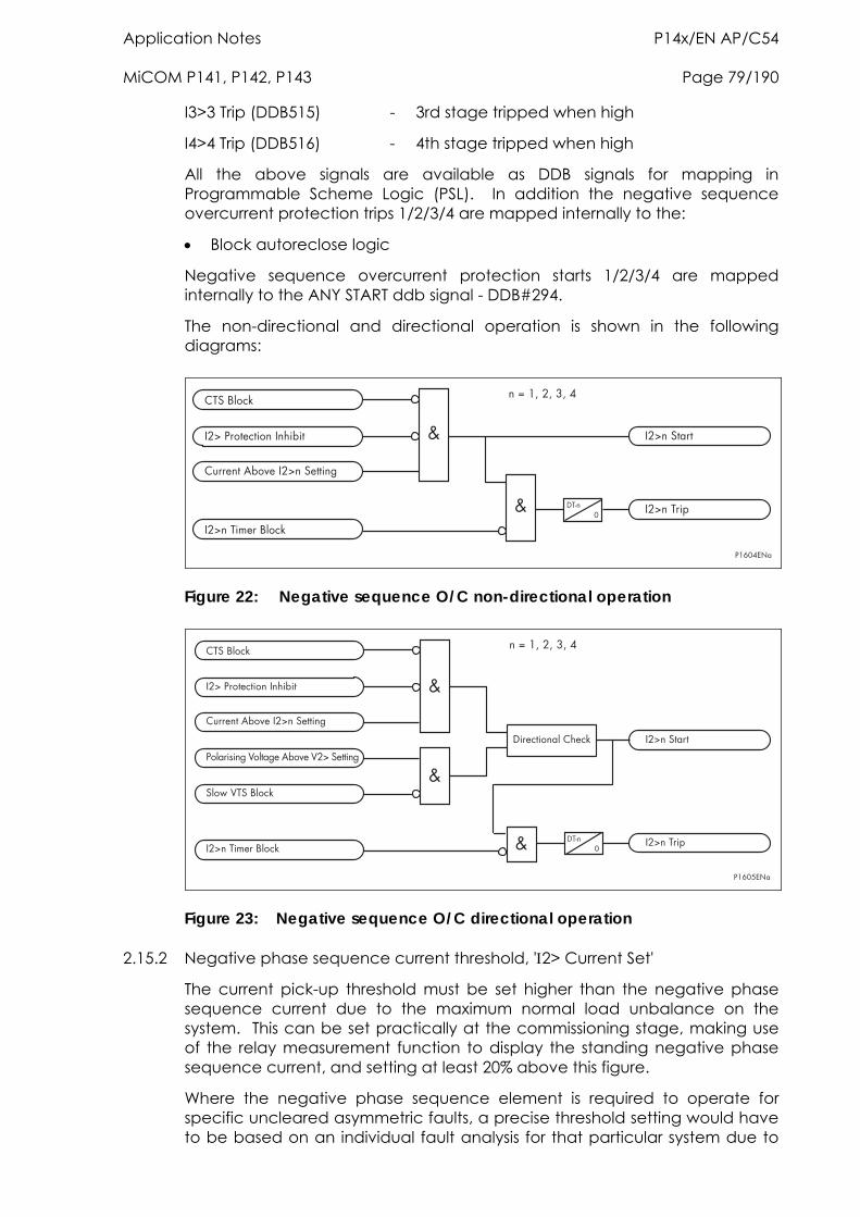
Application Notes P14x/EN AP/C54 MiCOM P141, P142, P143 Page 79/190
I3>3 Trip (DDB515) - 3rd stage tripped when high
I4>4 Trip (DDB516) - 4th stage tripped when high
All the above signals are available as DDB signals for mapping in Programmable Scheme Logic (PSL). In addition the negative sequence overcurrent protection trips 1/2/3/4 are mapped internally to the:
Block autoreclose logic
Negative sequence overcurrent protection starts 1/2/3/4 are mapped internally to the ANY START ddb signal - DDB#294.
The non-directional and directional operation is shown in the following diagrams:
�������
�� �������
�� �����������
���������������� ���������
�� ������������������ �
���� !"�
� �� �����#$�%��
��&��'��'�('�
Figure 22: Negative sequence O/C non-directional operation
�������
�� �������
�� �����������
���������������� ���������
�� ������������������ �
����)!"�
$�������������
�� �����#$�%��
��&��'��'�('�
������*����+�������������+� ��������
���,�+�������
�
Figure 23: Negative sequence O/C directional operation
2.15.2 Negative phase sequence current threshold, '2> Current Set'
The current pick-up threshold must be set higher than the negative phase sequence current due to the maximum normal load unbalance on the system. This can be set practically at the commissioning stage, making use of the relay measurement function to display the standing negative phase sequence current, and setting at least 20% above this figure.
Where the negative phase sequence element is required to operate for specific uncleared asymmetric faults, a precise threshold setting would have to be based on an individual fault analysis for that particular system due to
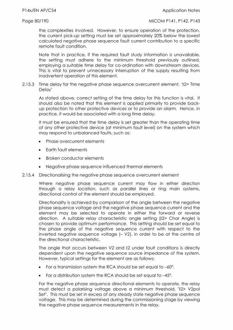
P14x/EN AP/C54 Application Notes Page 80/190 MiCOM P141, P142, P143
the complexities involved. However, to ensure operation of the protection, the current pick-up setting must be set approximately 20% below the lowest calculated negative phase sequence fault current contribution to a specific remote fault condition.
Note that in practice, if the required fault study information is unavailable, the setting must adhere to the minimum threshold previously outlined, employing a suitable time delay for co-ordination with downstream devices. This is vital to prevent unnecessary interruption of the supply resulting from inadvertent operation of this element.
2.15.3 Time delay for the negative phase sequence overcurrent element, ‘2> Time Delay’
As stated above, correct setting of the time delay for this function is vital. It should also be noted that this element is applied primarily to provide back-up protection to other protective devices or to provide an alarm. Hence, in practice, it would be associated with a long time delay.
It must be ensured that the time delay is set greater than the operating time of any other protective device (at minimum fault level) on the system which may respond to unbalanced faults, such as:
Phase overcurrent elements
Earth fault elements
Broken conductor elements
Negative phase sequence influenced thermal elements
2.15.4 Directionalising the negative phase sequence overcurrent element
Where negative phase sequence current may flow in either direction through a relay location, such as parallel lines or ring main systems, directional control of the element should be employed.
Directionality is achieved by comparison of the angle between the negative phase sequence voltage and the negative phase sequence current and the element may be selected to operate in either the forward or reverse direction. A suitable relay characteristic angle setting (2> Char Angle) is chosen to provide optimum performance. This setting should be set equal to the phase angle of the negative sequence current with respect to the inverted negative sequence voltage (– V2), in order to be at the centre of the directional characteristic.
The angle that occurs between V2 and 2 under fault conditions is directly dependent upon the negative sequence source impedance of the system. However, typical settings for the element are as follows;
For a transmission system the RCA should be set equal to –60°.
For a distribution system the RCA should be set equal to –45°.
For the negative phase sequence directional elements to operate, the relay must detect a polarising voltage above a minimum threshold, "2> V2pol Set". This must be set in excess of any steady state negative phase sequence voltage. This may be determined during the commissioning stage by viewing the negative phase sequence measurements in the relay.
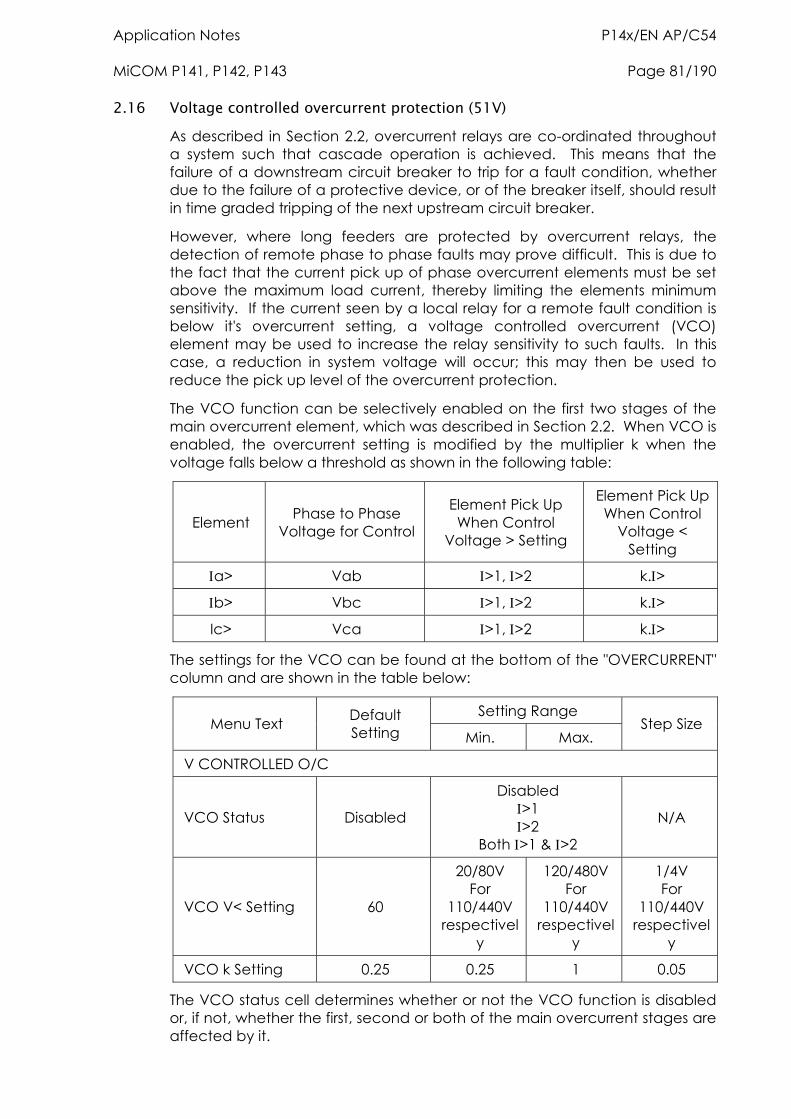
Application Notes P14x/EN AP/C54 MiCOM P141, P142, P143 Page 81/190
2.16 Voltage controlled overcurrent protection (51V) As described in Section 2.2, overcurrent relays are co-ordinated throughout a system such that cascade operation is achieved. This means that the failure of a downstream circuit breaker to trip for a fault condition, whether due to the failure of a protective device, or of the breaker itself, should result in time graded tripping of the next upstream circuit breaker.
However, where long feeders are protected by overcurrent relays, the detection of remote phase to phase faults may prove difficult. This is due to the fact that the current pick up of phase overcurrent elements must be set above the maximum load current, thereby limiting the elements minimum sensitivity. If the current seen by a local relay for a remote fault condition is below it's overcurrent setting, a voltage controlled overcurrent (VCO) element may be used to increase the relay sensitivity to such faults. In this case, a reduction in system voltage will occur; this may then be used to reduce the pick up level of the overcurrent protection.
The VCO function can be selectively enabled on the first two stages of the main overcurrent element, which was described in Section 2.2. When VCO is enabled, the overcurrent setting is modified by the multiplier k when the voltage falls below a threshold as shown in the following table:
Element Phase to Phase Voltage for Control
Element Pick Up When Control
Voltage > Setting
Element Pick Up When Control
Voltage < Setting
a> Vab >1, >2 k.>
b> Vbc >1, >2 k.>
Ic> Vca >1, >2 k.>
The settings for the VCO can be found at the bottom of the "OVERCURRENT" column and are shown in the table below:
Setting Range Menu Text Default
Setting Min. Max. Step Size
V CONTROLLED O/C
VCO Status Disabled
Disabled >1 >2
Both >1 & >2
N/A
VCO V< Setting 60
20/80V For
110/440V respectivel
y
120/480V For
110/440V respectivel
y
1/4V For
110/440V respectivel
y
VCO k Setting 0.25 0.25 1 0.05
The VCO status cell determines whether or not the VCO function is disabled or, if not, whether the first, second or both of the main overcurrent stages are affected by it.
P14x/EN AP/C54 Application Notes Page 82/190 MiCOM P141, P142, P143
The VCO V<setting cell determines the voltage threshold at which the current setting of the overcurrent stage/stages becomes reduced, noting that this occurs on a per phase basis.
Note that voltage dependent overcurrent relays are more often applied in generator protection applications in order to give adequate overcurrent relay sensitivity for close up fault conditions. The fault characteristic of this protection must then co-ordinate with any of the downstream overcurrent relays which are responsive to the current decrement condition. It therefore follows that if the P140 relay is to be applied on an outgoing feeder from a generator station, the use of voltage controlled overcurrent protection in the feeder relay may allow better co-ordination with the VCO relay on the generator. The settings in such an application will be directly dependent on those employed for the generator relay.
2.16.1 Setting guidelines
The "VCO k Setting" should be set low enough to allow operation for remote phase to phase faults, typically:
k = F
> x 1.2
where:
f = Minimum fault current expected for the remote fault
> = Phase current setting for the element to have VCO control e.g. If the overcurrent relay has a setting of 160% n, but the minimum fault current for the remote fault condition is only 80% n, then the required k factor is given by:
k = 0.8
1.6 x 1.2 = 0.42
The voltage threshold, "VCO V< Setting", would be set below the lowest system voltage that may occur under normal system operating conditions, whilst ensuring correct detection of the remote fault.
2.17 Circuit breaker fail protection (CBF) Following inception of a fault one or more main protection devices will operate and issue a trip output to the circuit breaker(s) associated with the faulted circuit. Operation of the circuit breaker is essential to isolate the fault, and prevent damage / further damage to the power system. For transmission/sub-transmission systems, slow fault clearance can also threaten system stability. It is therefore common practice to install circuit breaker failure protection, which monitors that the circuit breaker has opened within a reasonable time. If the fault current has not been interrupted following a set time delay from circuit breaker trip initiation, breaker failure protection (CBF) will operate.
CBF operation can be used to backtrip upstream circuit breakers to ensure that the fault is isolated correctly. CBF operation can also reset all start output contacts, ensuring that any blocks asserted on upstream protection are removed.
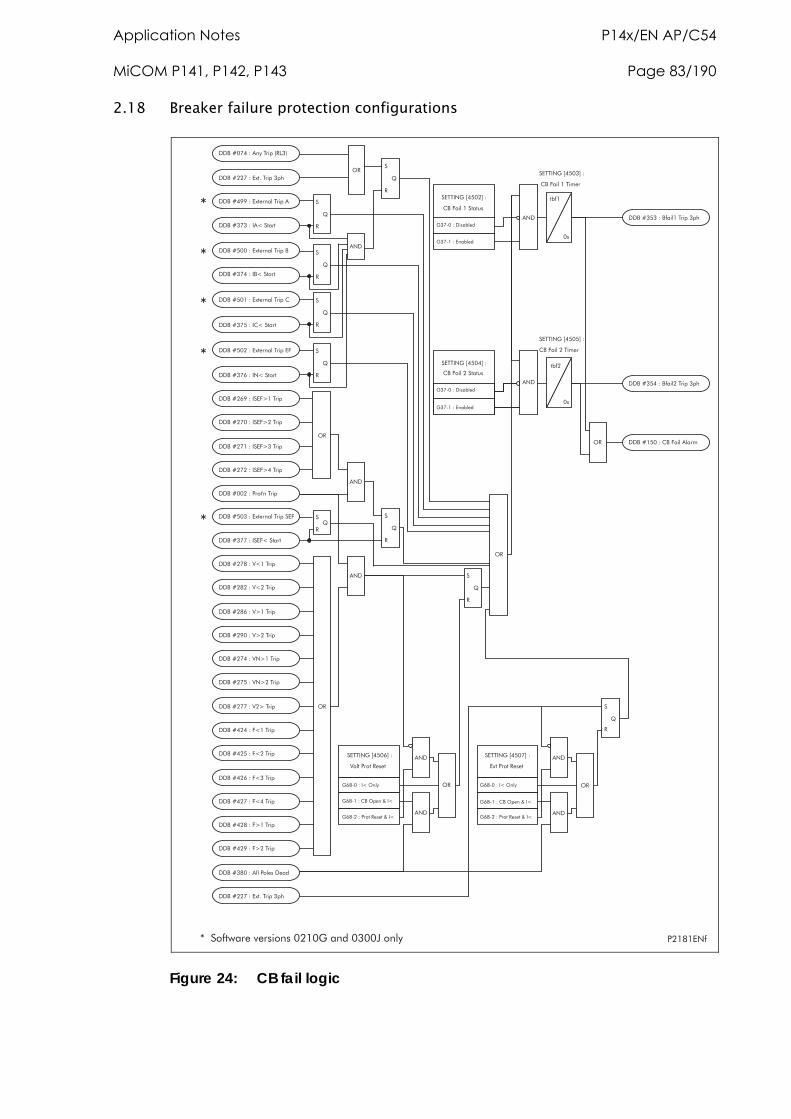
Application Notes P14x/EN AP/C54 MiCOM P141, P142, P143 Page 83/190
2.18 Breaker failure protection configurations
������������ ��� ��������������������
��������������� �!�"#$�%
������&���������� �!��!'
������&����(��)�����*
�+��
�
������&���������� �!��!'
�����������,-�.� �!��!'/#
�����������0�1����
�����������0�1����
�������&���0(1����
�������2���031����
�������4���51�� �!
������26���0�,)7�� �!
�����������0�,)7�� �!
�����������0�,)7�� �!
�����������0�,)7�� �!
/#
�����������8��9�� �!
�3�
������4����51�� �!
������42���57�� �!
������6����57�� �!
�����������537�� �!
�������&���537�� �!
�����������)1�� �!
�������&���)1�� �!
�������2���)1�� �!
�����������)1�� �!
�������4���)7�� �!
�������6���)7�� �!
������4��������8��� ����
/#
�����������,-�.� �!��!'
�3�
�����������0�,)1����
�
#
�24:����01�/���
�24:����(��/!���;�01
�24:����8���#� ���;�01
�, 03��<�&�2=��
5����8���#� ��
�24:����01�/���
�24:����(��/!���;�01
�24:����8���#� ���;�01
�, 03��<�&��=��
,-��8���#� ���3�
�3�
/#
�3�
�3�
/#
�
#
/#
���:������ +���
���:����,�+���
�, 03��<�&��=��
(��)��������>
���:������ +���
���:����,�+���
�, 03��<�&��=��
(��)��������>
�3�
�3�
�+��
�
/#
�, 03��<�&��=��
(��)����� �*�
�, 03��<�&�&=��
(��)����� �*�
�����������5�7� �!
������?
������?
8��4�,3�
�����&�����,-����� �!��,)
�����&�����,-����� �!�,)
�����&�����,-����� �!�(
�����&�����,-����� �!��
������66���,-����� �!��
�
#
������?
�
#
������?
���:������ +���
���:����,�+���
�, 03��<�&��=��
(��)��������>
�
#
������?
�
#
������?
�
#
������?
�
#
������?
�������?#
�3�
�
�
�
�
�
Figure 24: CB fail logic
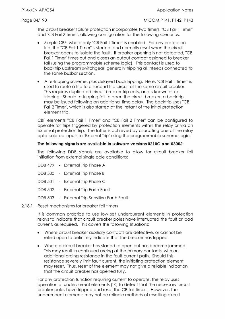
P14x/EN AP/C54 Application Notes Page 84/190 MiCOM P141, P142, P143
The circuit breaker failure protection incorporates two timers, "CB Fail 1 Timer" and "CB Fail 2 Timer", allowing configuration for the following scenarios:
Simple CBF, where only "CB Fail 1 Timer" is enabled. For any protection trip, the "CB Fail 1 Timer" is started, and normally reset when the circuit breaker opens to isolate the fault. If breaker opening is not detected, "CB Fail 1 Timer" times out and closes an output contact assigned to breaker fail (using the programmable scheme logic). This contact is used to backtrip upstream switchgear, generally tripping all infeeds connected to the same busbar section.
A re-tripping scheme, plus delayed backtripping. Here, "CB Fail 1 Timer" is used to route a trip to a second trip circuit of the same circuit breaker. This requires duplicated circuit breaker trip coils, and is known as re-tripping. Should re-tripping fail to open the circuit breaker, a backtrip may be issued following an additional time delay. The backtrip uses "CB Fail 2 Timer", which is also started at the instant of the initial protection element trip.
CBF elements "CB Fail 1 Timer" and "CB Fail 2 Timer" can be configured to operate for trips triggered by protection elements within the relay or via an external protection trip. The latter is achieved by allocating one of the relay opto-isolated inputs to "External Trip" using the programmable scheme logic.
The following signals are available in software versions 0210G and 0300J:
The following DDB signals are available to allow for circuit breaker fail initiation from external single pole conditions:
DDB 499 - External Trip Phase A
DDB 500 - External Trip Phase B
DDB 501 - External Trip Phase C
DDB 502 - External Trip Earth Fault
DDB 503 - External Trip Sensitive Earth Fault
2.18.1 Reset mechanisms for breaker fail timers
It is common practice to use low set undercurrent elements in protection relays to indicate that circuit breaker poles have interrupted the fault or load current, as required. This covers the following situations:
Where circuit breaker auxiliary contacts are defective, or cannot be relied upon to definitely indicate that the breaker has tripped.
Where a circuit breaker has started to open but has become jammed. This may result in continued arcing at the primary contacts, with an additional arcing resistance in the fault current path. Should this resistance severely limit fault current, the initiating protection element may reset. Thus, reset of the element may not give a reliable indication that the circuit breaker has opened fully.
For any protection function requiring current to operate, the relay uses operation of undercurrent elements (<) to detect that the necessary circuit breaker poles have tripped and reset the CB fail timers. However, the undercurrent elements may not be reliable methods of resetting circuit
Application Notes P14x/EN AP/C54 MiCOM P141, P142, P143 Page 85/190
breaker fail in all applications. For example:
Where non-current operated protection, such as under/overvoltage or under/overfrequency, derives measurements from a line connected voltage transformer. Here, < only gives a reliable reset method if the protected circuit would always have load current flowing. Detecting drop-off of the initiating protection element might be a more reliable method.
Where non-current operated protection, such as under/overvoltage or under/overfrequency, derives measurements from a busbar connected voltage transformer. Again using < would rely upon the feeder normally being loaded. Also, tripping the circuit breaker may not remove the initiating condition from the busbar, and hence drop-off of the protection element may not occur. In such cases, the position of the circuit breaker auxiliary contacts may give the best reset method.
Resetting of the CBF is possible from a breaker open indication (from the relay’s pole dead logic) or from a protection reset. In these cases resetting is only allowed provided the undercurrent elements have also reset. The resetting options are summarised in the following table.
Initiation (Menu Selectable) CB Fail Timer Reset Mechanism
Current based protection
The resetting mechanism is fixed (e.g. 50/51/46/21/87..) [A< operates] & [B< operates] & [C< operates] & [N< operates]
Sensitive earth fault element The resetting mechanism is fixed. [SEF< Operates]
Non-current based protection (e.g. 27/59/81/32L..)
Three options are available. The user can Select from the following options. [All < and N< elements operate] [Protection element reset] AND [All < and N< elements operate] CB open (all 3 poles) AND [All I< and N< elements operate]
External protection
Three options are available. The user can select any or all of the options. [All < and N< elements operate] [External trip reset] AND [All < and N< elements operate] CB open (all 3 poles) AND [All < and N< elements operate]
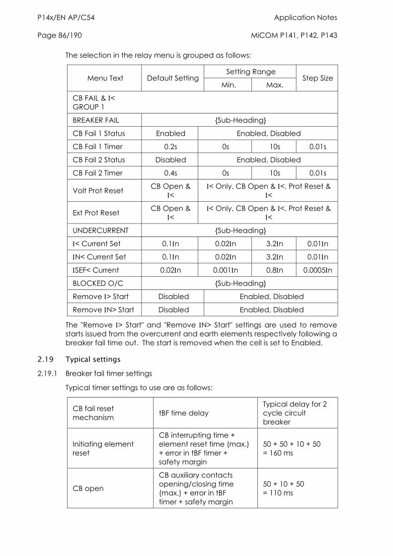
P14x/EN AP/C54 Application Notes Page 86/190 MiCOM P141, P142, P143
The selection in the relay menu is grouped as follows:
Setting Range Menu Text Default Setting
Min. Max. Step Size
CB FAIL & < GROUP 1
BREAKER FAIL {Sub-Heading}
CB Fail 1 Status Enabled Enabled, Disabled
CB Fail 1 Timer 0.2s 0s 10s 0.01s
CB Fail 2 Status Disabled Enabled, Disabled
CB Fail 2 Timer 0.4s 0s 10s 0.01s
Volt Prot Reset CB Open & <
< Only, CB Open & <, Prot Reset & <
Ext Prot Reset CB Open & <
< Only, CB Open & <, Prot Reset & <
UNDERCURRENT {Sub-Heading}
< Current Set 0.1n 0.02n 3.2n 0.01n
N< Current Set 0.1n 0.02n 3.2n 0.01n
SEF< Current 0.02n 0.001n 0.8n 0.0005n
BLOCKED O/C {Sub-Heading}
Remove > Start Disabled Enabled, Disabled
Remove N> Start Disabled Enabled, Disabled
The "Remove > Start" and "Remove N> Start" settings are used to remove starts issued from the overcurrent and earth elements respectively following a breaker fail time out. The start is removed when the cell is set to Enabled.
2.19 Typical settings 2.19.1 Breaker fail timer settings
Typical timer settings to use are as follows:
CB fail reset mechanism tBF time delay
Typical delay for 2 cycle circuit breaker
Initiating element reset
CB interrupting time + element reset time (max.) + error in tBF timer + safety margin
50 + 50 + 10 + 50 = 160 ms
CB open
CB auxiliary contacts opening/closing time (max.) + error in tBF timer + safety margin
50 + 10 + 50 = 110 ms
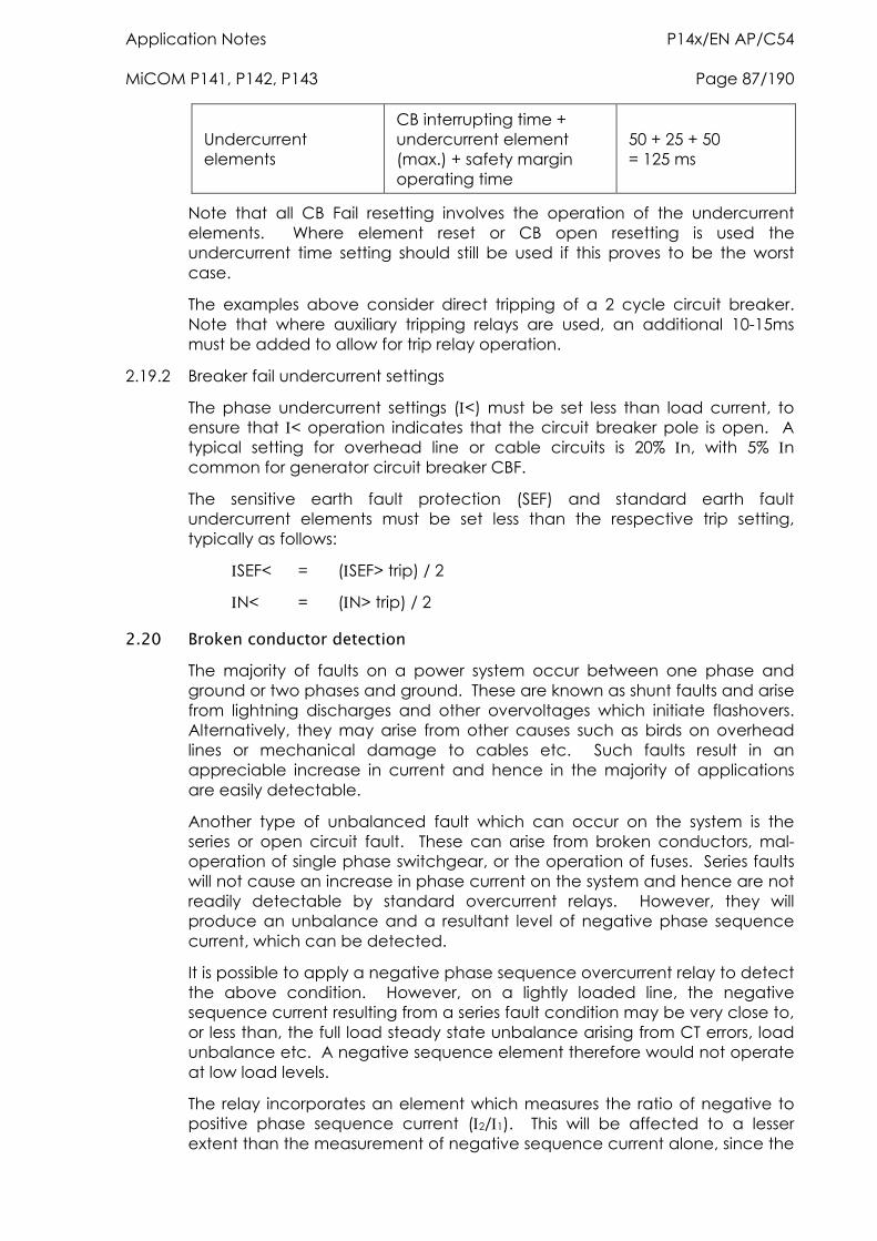
Application Notes P14x/EN AP/C54 MiCOM P141, P142, P143 Page 87/190
Undercurrent elements
CB interrupting time + undercurrent element (max.) + safety margin operating time
50 + 25 + 50 = 125 ms
Note that all CB Fail resetting involves the operation of the undercurrent elements. Where element reset or CB open resetting is used the undercurrent time setting should still be used if this proves to be the worst case.
The examples above consider direct tripping of a 2 cycle circuit breaker. Note that where auxiliary tripping relays are used, an additional 10-15ms must be added to allow for trip relay operation.
2.19.2 Breaker fail undercurrent settings
The phase undercurrent settings (<) must be set less than load current, to ensure that < operation indicates that the circuit breaker pole is open. A typical setting for overhead line or cable circuits is 20% n, with 5% n common for generator circuit breaker CBF.
The sensitive earth fault protection (SEF) and standard earth fault undercurrent elements must be set less than the respective trip setting, typically as follows:
SEF< = (SEF> trip) / 2
N< = (N> trip) / 2
2.20 Broken conductor detection The majority of faults on a power system occur between one phase and ground or two phases and ground. These are known as shunt faults and arise from lightning discharges and other overvoltages which initiate flashovers. Alternatively, they may arise from other causes such as birds on overhead lines or mechanical damage to cables etc. Such faults result in an appreciable increase in current and hence in the majority of applications are easily detectable.
Another type of unbalanced fault which can occur on the system is the series or open circuit fault. These can arise from broken conductors, mal-operation of single phase switchgear, or the operation of fuses. Series faults will not cause an increase in phase current on the system and hence are not readily detectable by standard overcurrent relays. However, they will produce an unbalance and a resultant level of negative phase sequence current, which can be detected.
It is possible to apply a negative phase sequence overcurrent relay to detect the above condition. However, on a lightly loaded line, the negative sequence current resulting from a series fault condition may be very close to, or less than, the full load steady state unbalance arising from CT errors, load unbalance etc. A negative sequence element therefore would not operate at low load levels.
The relay incorporates an element which measures the ratio of negative to positive phase sequence current (2/1). This will be affected to a lesser extent than the measurement of negative sequence current alone, since the
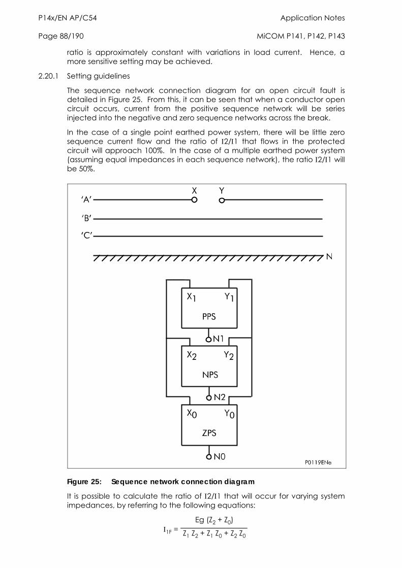
P14x/EN AP/C54 Application Notes Page 88/190 MiCOM P141, P142, P143
ratio is approximately constant with variations in load current. Hence, a more sensitive setting may be achieved.
2.20.1 Setting guidelines
The sequence network connection diagram for an open circuit fault is detailed in Figure 25. From this, it can be seen that when a conductor open circuit occurs, current from the positive sequence network will be series injected into the negative and zero sequence networks across the break.
In the case of a single point earthed power system, there will be little zero sequence current flow and the ratio of 2/1 that flows in the protected circuit will approach 100%. In the case of a multiple earthed power system (assuming equal impedances in each sequence network), the ratio 2/1 will be 50%.
Figure 25: Sequence network connection diagram
It is possible to calculate the ratio of 2/1 that will occur for varying system impedances, by referring to the following equations:
1F = Eg (Z2 + Z0)
Z1 Z2 + Z1 Z0 + Z2 Z0
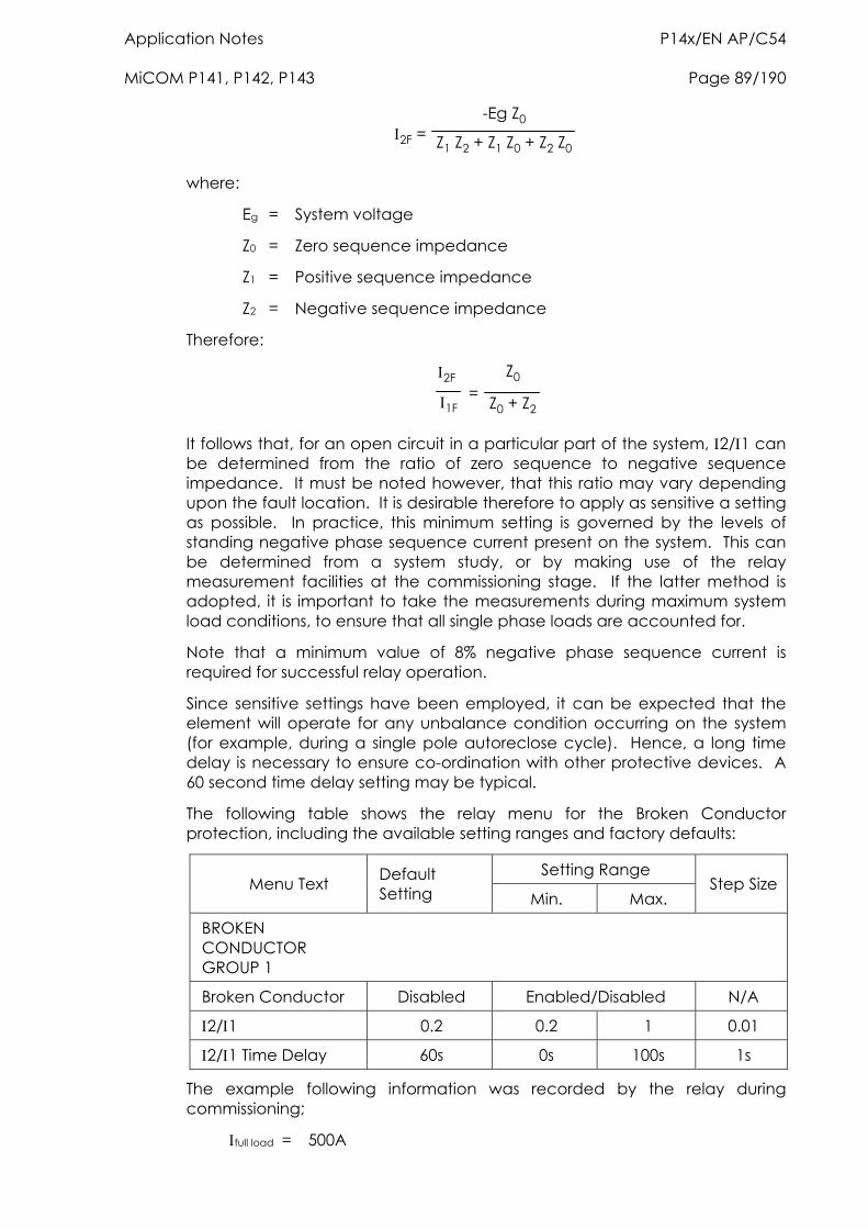
Application Notes P14x/EN AP/C54 MiCOM P141, P142, P143 Page 89/190
2F = -Eg Z0
Z1 Z2 + Z1 Z0 + Z2 Z0
where:
Eg = System voltage
Z0 = Zero sequence impedance
Z1 = Positive sequence impedance
Z2 = Negative sequence impedance
Therefore:
2F
1F =
Z0
Z0 + Z2
It follows that, for an open circuit in a particular part of the system, 2/1 can be determined from the ratio of zero sequence to negative sequence impedance. It must be noted however, that this ratio may vary depending upon the fault location. It is desirable therefore to apply as sensitive a setting as possible. In practice, this minimum setting is governed by the levels of standing negative phase sequence current present on the system. This can be determined from a system study, or by making use of the relay measurement facilities at the commissioning stage. If the latter method is adopted, it is important to take the measurements during maximum system load conditions, to ensure that all single phase loads are accounted for.
Note that a minimum value of 8% negative phase sequence current is required for successful relay operation.
Since sensitive settings have been employed, it can be expected that the element will operate for any unbalance condition occurring on the system (for example, during a single pole autoreclose cycle). Hence, a long time delay is necessary to ensure co-ordination with other protective devices. A 60 second time delay setting may be typical.
The following table shows the relay menu for the Broken Conductor protection, including the available setting ranges and factory defaults:
Setting Range Menu Text Default
Setting Min. Max. Step Size
BROKEN CONDUCTOR GROUP 1
Broken Conductor Disabled Enabled/Disabled N/A
2/1 0.2 0.2 1 0.01
2/1 Time Delay 60s 0s 100s 1s
The example following information was recorded by the relay during commissioning;
full load = 500A
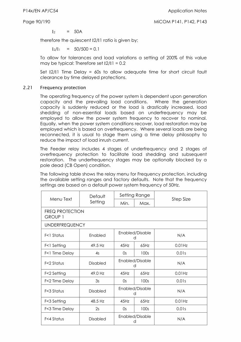
P14x/EN AP/C54 Application Notes Page 90/190 MiCOM P141, P142, P143
2 = 50A
therefore the quiescent 2/1 ratio is given by;
2/1 = 50/500 = 0.1
To allow for tolerances and load variations a setting of 200% of this value may be typical: Therefore set 2/1 = 0.2
Set 2/1 Time Delay = 60s to allow adequate time for short circuit fault clearance by time delayed protections.
2.21 Frequency protection The operating frequency of the power system is dependent upon generation capacity and the prevailing load conditions. Where the generation capacity is suddenly reduced or the load is drastically increased, load shedding of non-essential loads based on underfrequency may be employed to allow the power system frequency to recover to nominal. Equally, when the power system conditions recover, load restoration may be employed which is based on overfrequency. Where several loads are being reconnected, it is usual to stage them using a time delay philosophy to reduce the impact of load inrush current.
The Feeder relay includes 4 stages of underfrequency and 2 stages of overfrequency protection to facilitate load shedding and subsequent restoration. The underfrequency stages may be optionally blocked by a pole dead (CB Open) condition.
The following table shows the relay menu for Frequency protection, including the available setting ranges and factory defaults. Note that the frequency settings are based on a default power system frequency of 50Hz.
Setting Range Menu Text Default
Setting Min. Max. Step Size
FREQ PROTECTION GROUP 1
UNDERFREQUENCY
F<1 Status Enabled Enabled/Disabled N/A
F<1 Setting 49.5 Hz 45Hz 65Hz 0.01Hz
F<1 Time Delay 4s 0s 100s 0.01s
F<2 Status Disabled Enabled/Disabled N/A
F<2 Setting 49.0 Hz 45Hz 65Hz 0.01Hz
F<2 Time Delay 3s 0s 100s 0.01s
F<3 Status Disabled Enabled/Disabled N/A
F<3 Setting 48.5 Hz 45Hz 65Hz 0.01Hz
F<3 Time Delay 2s 0s 100s 0.01s
F<4 Status Disabled Enabled/Disabled N/A
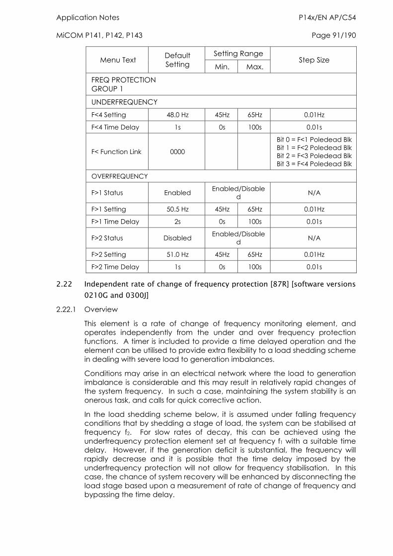
Application Notes P14x/EN AP/C54 MiCOM P141, P142, P143 Page 91/190
Setting Range Menu Text Default
Setting Min. Max. Step Size
FREQ PROTECTION GROUP 1
UNDERFREQUENCY
F<4 Setting 48.0 Hz 45Hz 65Hz 0.01Hz
F<4 Time Delay 1s 0s 100s 0.01s
F< Function Link 0000
Bit 0 = F<1 Poledead Blk Bit 1 = F<2 Poledead Blk Bit 2 = F<3 Poledead Blk Bit 3 = F<4 Poledead Blk
OVERFREQUENCY
F>1 Status Enabled Enabled/Disabled N/A
F>1 Setting 50.5 Hz 45Hz 65Hz 0.01Hz
F>1 Time Delay 2s 0s 100s 0.01s
F>2 Status Disabled Enabled/Disabled N/A
F>2 Setting 51.0 Hz 45Hz 65Hz 0.01Hz
F>2 Time Delay 1s 0s 100s 0.01s
2.22 Independent rate of change of frequency protection [87R] [software versions 0210G and 0300J]
2.22.1 Overview
This element is a rate of change of frequency monitoring element, and operates independently from the under and over frequency protection functions. A timer is included to provide a time delayed operation and the element can be utilised to provide extra flexibility to a load shedding scheme in dealing with severe load to generation imbalances.
Conditions may arise in an electrical network where the load to generation imbalance is considerable and this may result in relatively rapid changes of the system frequency. In such a case, maintaining the system stability is an onerous task, and calls for quick corrective action.
In the load shedding scheme below, it is assumed under falling frequency conditions that by shedding a stage of load, the system can be stabilised at frequency f2. For slow rates of decay, this can be achieved using the underfrequency protection element set at frequency f1 with a suitable time delay. However, if the generation deficit is substantial, the frequency will rapidly decrease and it is possible that the time delay imposed by the underfrequency protection will not allow for frequency stabilisation. In this case, the chance of system recovery will be enhanced by disconnecting the load stage based upon a measurement of rate of change of frequency and bypassing the time delay.
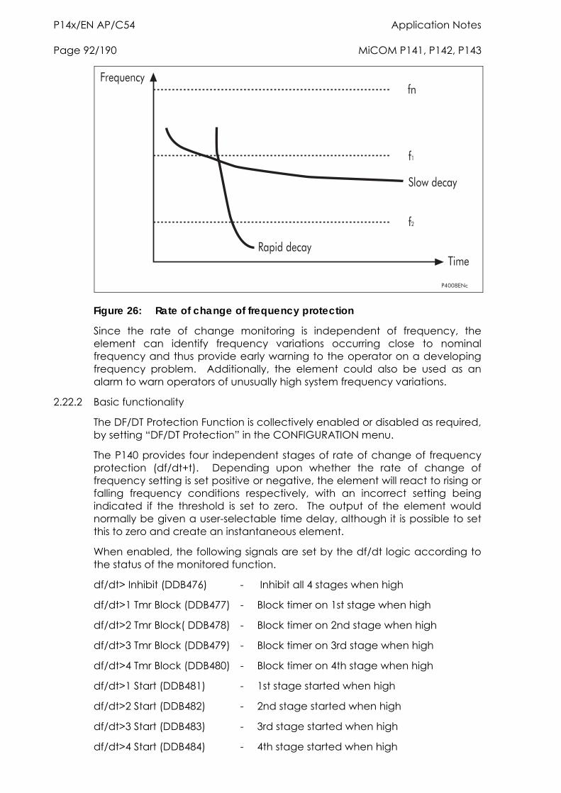
P14x/EN AP/C54 Application Notes Page 92/190 MiCOM P141, P142, P143
8���4,3@
��
��
��
�������@�
#!�����@�
)�A>��@�
�*�
Figure 26: Rate of change of frequency protection
Since the rate of change monitoring is independent of frequency, the element can identify frequency variations occurring close to nominal frequency and thus provide early warning to the operator on a developing frequency problem. Additionally, the element could also be used as an alarm to warn operators of unusually high system frequency variations.
2.22.2 Basic functionality
The DF/DT Protection Function is collectively enabled or disabled as required, by setting “DF/DT Protection” in the CONFIGURATION menu.
The P140 provides four independent stages of rate of change of frequency protection (df/dt+t). Depending upon whether the rate of change of frequency setting is set positive or negative, the element will react to rising or falling frequency conditions respectively, with an incorrect setting being indicated if the threshold is set to zero. The output of the element would normally be given a user-selectable time delay, although it is possible to set this to zero and create an instantaneous element.
When enabled, the following signals are set by the df/dt logic according to the status of the monitored function.
df/dt> Inhibit (DDB476) - Inhibit all 4 stages when high
df/dt>1 Tmr Block (DDB477) - Block timer on 1st stage when high
df/dt>2 Tmr Block( DDB478) - Block timer on 2nd stage when high
df/dt>3 Tmr Block (DDB479) - Block timer on 3rd stage when high
df/dt>4 Tmr Block (DDB480) - Block timer on 4th stage when high
df/dt>1 Start (DDB481) - 1st stage started when high
df/dt>2 Start (DDB482) - 2nd stage started when high
df/dt>3 Start (DDB483) - 3rd stage started when high
df/dt>4 Start (DDB484) - 4th stage started when high
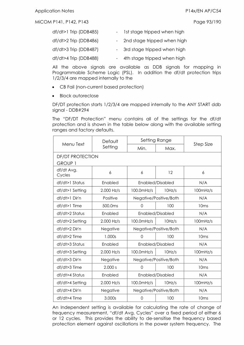
Application Notes P14x/EN AP/C54 MiCOM P141, P142, P143 Page 93/190
df/dt>1 Trip (DDB485) - 1st stage tripped when high
df/dt>2 Trip (DDB486) - 2nd stage tripped when high
df/dt>3 Trip (DDB487) - 3rd stage tripped when high
df/dt>4 Trip (DDB488) - 4th stage tripped when high
All the above signals are available as DDB signals for mapping in Programmable Scheme Logic (PSL). In addition the df/dt protection trips 1/2/3/4 are mapped internally to the
CB Fail (non-current based protection)
Block autoreclose
DF/DT protection starts 1/2/3/4 are mapped internally to the ANY START ddb signal - DDB#294
The “DF/DT Protection” menu contains all of the settings for the df/dt protection and is shown in the table below along with the available setting ranges and factory defaults.
Setting Range Menu Text Default
Setting Min. Max. Step Size
DF/DT PROTECTION GROUP 1 df/dt Avg. Cycles 6 6 12 6
df/dt>1 Status Enabled Enabled/Disabled N/A
df/dt>1 Setting 2.000 Hz/s 100.0mHz/s 10Hz/s 100mHz/s
df/dt>1 Dir'n Positive Negative/Positive/Both N/A
df/dt>1 Time 500.0ms 0 100 10ms
df/dt>2 Status Enabled Enabled/Disabled N/A
df/dt>2 Setting 2.000 Hz/s 100.0mHz/s 10Hz/s 100mHz/s
df/dt>2 Dir'n Negative Negative/Positive/Both N/A
df/dt>2 Time 1.000s 0 100 10ms
df/dt>3 Status Enabled Enabled/Disabled N/A
df/dt>3 Setting 2.000 Hz/s 100.0mHz/s 10Hz/s 100mHz/s
df/dt>3 Dir'n Negative Negative/Positive/Both N/A
df/dt>3 Time 2.000 s 0 100 10ms
df/dt>4 Status Enabled Enabled/Disabled N/A
df/dt>4 Setting 2.000 Hz/s 100.0mHz/s 10Hz/s 100mHz/s
df/dt>4 Dir'n Negative Negative/Positive/Both N/A
df/dt>4 Time 3.000s 0 100 10ms
An Independent setting is available for calculating the rate of change of frequency measurement, “df/dt Avg. Cycles” over a fixed period of either 6 or 12 cycles. This provides the ability to de-sensitise the frequency based protection element against oscillations in the power system frequency. The
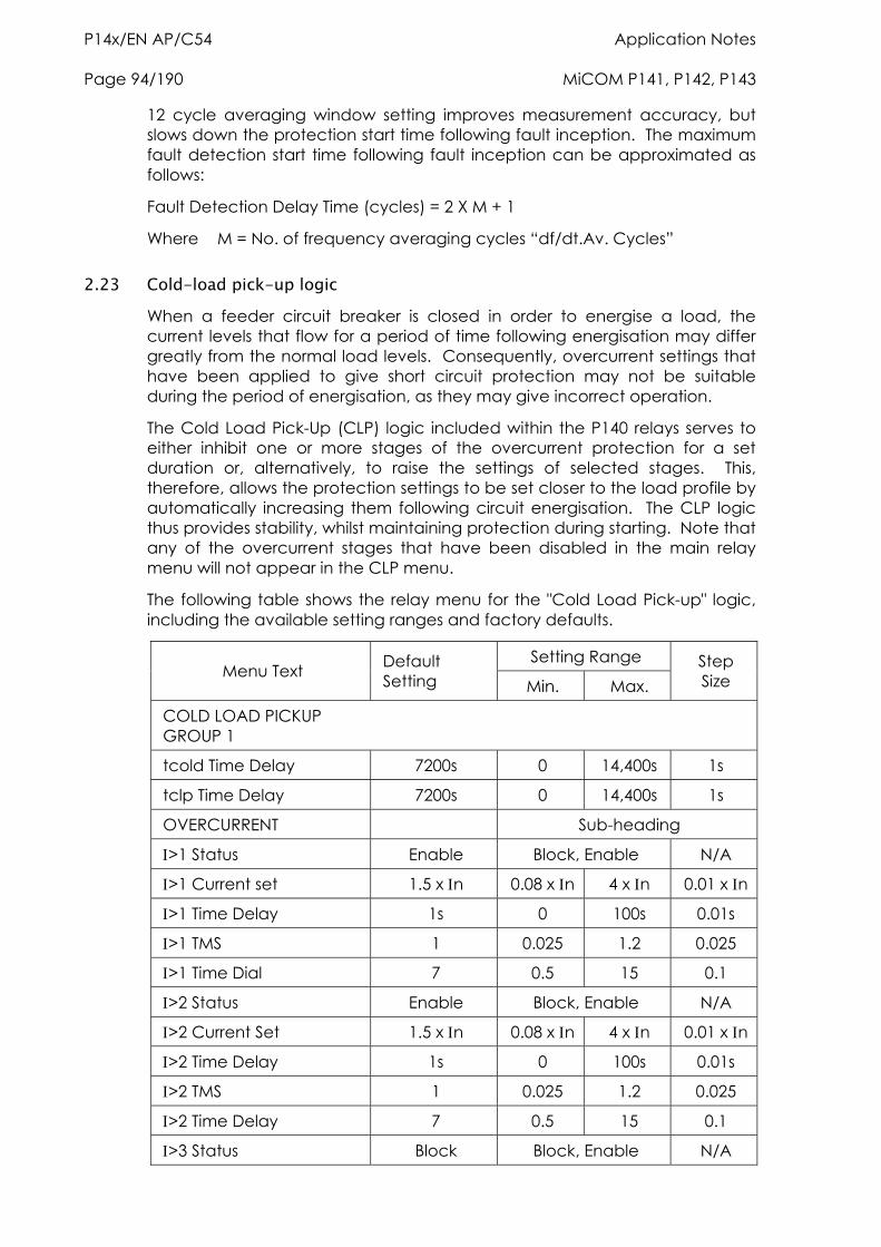
P14x/EN AP/C54 Application Notes Page 94/190 MiCOM P141, P142, P143
12 cycle averaging window setting improves measurement accuracy, but slows down the protection start time following fault inception. The maximum fault detection start time following fault inception can be approximated as follows:
Fault Detection Delay Time (cycles) = 2 X M + 1
Where M = No. of frequency averaging cycles “df/dt.Av. Cycles”
2.23 Cold-load pick-up logic When a feeder circuit breaker is closed in order to energise a load, the current levels that flow for a period of time following energisation may differ greatly from the normal load levels. Consequently, overcurrent settings that have been applied to give short circuit protection may not be suitable during the period of energisation, as they may give incorrect operation.
The Cold Load Pick-Up (CLP) logic included within the P140 relays serves to either inhibit one or more stages of the overcurrent protection for a set duration or, alternatively, to raise the settings of selected stages. This, therefore, allows the protection settings to be set closer to the load profile by automatically increasing them following circuit energisation. The CLP logic thus provides stability, whilst maintaining protection during starting. Note that any of the overcurrent stages that have been disabled in the main relay menu will not appear in the CLP menu.
The following table shows the relay menu for the "Cold Load Pick-up" logic, including the available setting ranges and factory defaults.
Setting Range Menu Text Default
Setting Min. Max. Step Size
COLD LOAD PICKUP GROUP 1
tcold Time Delay 7200s 0 14,400s 1s
tclp Time Delay 7200s 0 14,400s 1s
OVERCURRENT Sub-heading
>1 Status Enable Block, Enable N/A
>1 Current set 1.5 x n 0.08 x n 4 x n 0.01 x n
>1 Time Delay 1s 0 100s 0.01s
>1 TMS 1 0.025 1.2 0.025
>1 Time Dial 7 0.5 15 0.1
>2 Status Enable Block, Enable N/A
>2 Current Set 1.5 x n 0.08 x n 4 x n 0.01 x n
>2 Time Delay 1s 0 100s 0.01s
>2 TMS 1 0.025 1.2 0.025
>2 Time Delay 7 0.5 15 0.1
>3 Status Block Block, Enable N/A
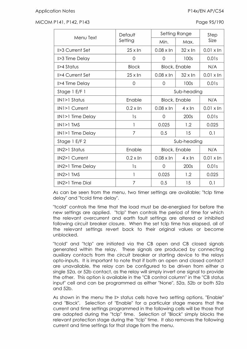
Application Notes P14x/EN AP/C54 MiCOM P141, P142, P143 Page 95/190
Setting Range Menu Text Default
Setting Min. Max. Step Size
>3 Current Set 25 x n 0.08 x n 32 x n 0.01 x n
>3 Time Delay 0 0 100s 0.01s
>4 Status Block Block, Enable N/A
>4 Current Set 25 x n 0.08 x n 32 x n 0.01 x n
>4 Time Delay 0 0 100s 0.01s
Stage 1 E/F 1 Sub-heading
N1>1 Status Enable Block, Enable N/A
N1>1 Current 0.2 x n 0.08 x n 4 x n 0.01 x n
N1>1 Time Delay 1s 0 200s 0.01s
N1>1 TMS 1 0.025 1.2 0.025
N1>1 Time Delay 7 0.5 15 0.1
Stage 1 E/F 2 Sub-heading
N2>1 Status Enable Block, Enable N/A
N2>1 Current 0.2 x n 0.08 x n 4 x n 0.01 x n
N2>1 Time Delay 1s 0 200s 0.01s
N2>1 TMS 1 0.025 1.2 0.025
N2>1 Time Dial 7 0.5 15 0.1
As can be seen from the menu, two timer settings are available; "tclp time delay" and "tcold time delay".
"tcold" controls the time that the load must be de-energised for before the new settings are applied. "tclp" then controls the period of time for which the relevant overcurrent and earth fault settings are altered or inhibited following circuit breaker closure. When the set tclp time has elapsed, all of the relevant settings revert back to their original values or become unblocked.
"tcold" and "tclp" are initiated via the CB open and CB closed signals generated within the relay. These signals are produced by connecting auxiliary contacts from the circuit breaker or starting device to the relays opto-inputs. It is important to note that if both an open and closed contact are unavailable, the relay can be configured to be driven from either a single 52a, or 52b contact, as the relay will simply invert one signal to provide the other. This option is available in the "CB control column" in the "CB status input" cell and can be programmed as either "None", 52a, 52b or both 52a and 52b.
As shown in the menu the > status cells have two setting options, "Enable" and "Block". Selection of "Enable" for a particular stage means that the current and time settings programmed in the following cells will be those that are adopted during the "tclp" time. Selection of "Block" simply blocks the relevant protection stage during the "tclp" time. It also removes the following current and time settings for that stage from the menu.
P14x/EN AP/C54 Application Notes Page 96/190 MiCOM P141, P142, P143
The CLP logic is included for each of the four overcurrent stages and the first stages of the measured (EF1) and derived (EF2) earth fault protection. Note that the CLP logic is enabled/disabled within the configuration column.
The following sections describe applications where the CLP logic may be useful and the settings that need to be applied.
2.23.1 Air conditioning/resistive heating loads
Where a feeder is being used to supply air conditioning or resistive heating loads there may be a conflict between the ‘steady state’ overcurrent settings and those required following energisation. This is due to the temporary increase in load current that may arise during this period. The CLP logic can be used to alter the applied settings during this time.
In this situation, “Enable” should be selected (from the "> status" option) and the temporary current and time settings can then be programmed. These settings would be chosen in accordance with the expected load profile. Where it is not necessary to alter the setting of a particular stage, the CLP settings should be set to the required overcurrent settings.
It may not be necessary to alter the protection settings following a short supply interruption. In this case a suitable tcold timer setting can be used.
It should be noted that it is not possible to alter any of the directional settings in the CLP logic.
2.23.2 Motor feeders
In general, feeders supplying motor loads would be protected by a dedicated motor protection device, such as the P240 from the MiCOM range. However, if no specific protection has been applied (possibly due to economic reasons) then the CLP logic in the P140 may be used to modify the overcurrent settings accordingly during starting.
Depending upon the magnitude and duration of the motor starting current, it may be sufficient to simply block operation of instantaneous elements or, if the start duration is long, the time delayed protection settings may also need to be raised. Hence, a combination of both blocking and raising of settings of the relevant overcurrent stages may be adopted. The CLP overcurrent settings in this case must be chosen with regard to the motor starting characteristic.
As previously described, the CLP logic includes the option of either blocking or raising the settings of the first stage of the standard earth fault protection. This may be useful where instantaneous earth fault protection is required to be applied to the motor. During conditions of motor starting, it is likely that incorrect operation of the earth fault element would occur due to asymmetric CT saturation. This is a result of the high level of starting current causing saturation of one or more of the line CT’s feeding the overcurrent / earth fault protection. The resultant transient imbalance in the secondary line current quantities is thus detected by the residually connected earth fault element. For this reason, it is normal to either apply a nominal time delay to the element, or to utilise a series stabilising resistor.
The CLP logic may be utilised to allow reduced operating times or current settings to be applied to the earth fault element under normal running
Application Notes P14x/EN AP/C54 MiCOM P141, P142, P143 Page 97/190
conditions. These settings could then be raised prior to motor starting, via the logic.
2.23.3 Earth fault protection applied to transformers
Where an earth fault relay is residually connected on the primary side of a delta-star transformer, no time delay is required for co-ordination purposes, due to the presence of the delta winding. However, a nominal time delay or stabilising resistor is recommended, to ensure transient stability during transformer energisation.
The CLP logic may be utilised in a similar manner to that previously described for the motor application.
It should be noted that this method will not provide stability in the event of asymmetric CT saturation which occurs as a result of an unbalanced fault condition. If problems of this nature are encountered, the best solution would still be the use of a stabilising resistor.
2.23.4 Switch onto fault protection (SOTF)
In some feeder applications, fast tripping may be required if a fault is present on the feeder when it is energised. Such faults may be due to a fault condition not having been removed from the feeder, or due to earthing clamps having been left on following maintenance. In either case, it may be desirable to clear the fault condition in an accelerated time, rather than waiting for the time delay associated with IDMT overcurrent protection.
The above situation may be catered for by the CLP logic. Selected overcurrent / earth fault stages could be set to instantaneous operation for a defined period following circuit breaker closure (typically 200ms). Hence, instantaneous fault clearance would be achieved for a switch onto fault (SOTF) condition.
2.24 Selective overcurrent logic Section 3.1 describes the use of non-cascade protection schemes which make use of start contacts from downstream relays connected to block operation of upstream relays. In the case of Selective Overcurrent Logic (SOL), the start contacts are used to raise the time delays of upstream relays, instead of blocking. This provides an alternative approach to achieving non-cascade types of overcurrent scheme. This may be more familiar to some utilities than the blocked overcurrent arrangement.
The SOL function provides the ability to temporarily increase the time delay settings of the third and fourth stages of phase overcurrent, derived and measured earth fault and sensitive earth fault protection elements. This logic is initiated by energisation of the appropriate opto-isolated input.
To allow time for a start contact to initiate a change of setting, the time settings of the third and fourth stages should include a nominal delay. Guidelines for minimum time settings will be identical to those advised for the blocked overcurrent scheme.
The following table shows the relay menu for the selective logic, including the available setting ranges and factory defaults:
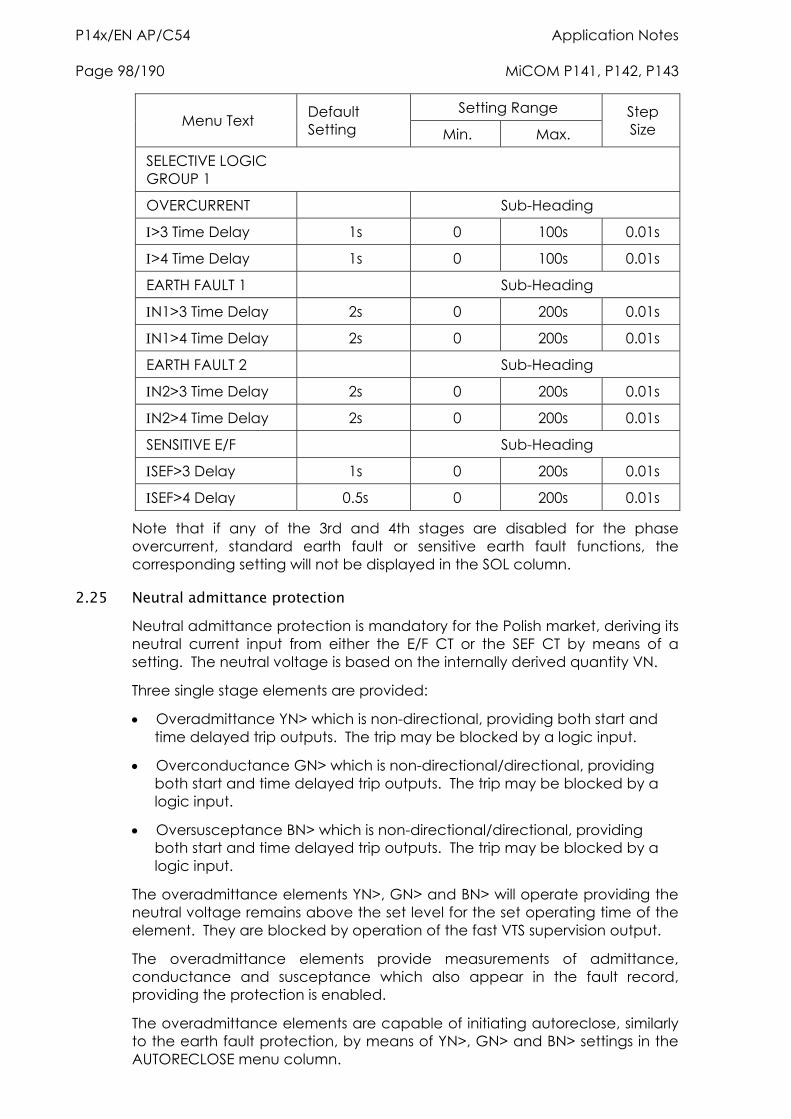
P14x/EN AP/C54 Application Notes Page 98/190 MiCOM P141, P142, P143
Setting Range Menu Text Default
Setting Min. Max. Step Size
SELECTIVE LOGIC GROUP 1
OVERCURRENT Sub-Heading
>3 Time Delay 1s 0 100s 0.01s
>4 Time Delay 1s 0 100s 0.01s
EARTH FAULT 1 Sub-Heading
N1>3 Time Delay 2s 0 200s 0.01s
N1>4 Time Delay 2s 0 200s 0.01s
EARTH FAULT 2 Sub-Heading
N2>3 Time Delay 2s 0 200s 0.01s
N2>4 Time Delay 2s 0 200s 0.01s
SENSITIVE E/F Sub-Heading
SEF>3 Delay 1s 0 200s 0.01s
SEF>4 Delay 0.5s 0 200s 0.01s
Note that if any of the 3rd and 4th stages are disabled for the phase overcurrent, standard earth fault or sensitive earth fault functions, the corresponding setting will not be displayed in the SOL column.
2.25 Neutral admittance protection Neutral admittance protection is mandatory for the Polish market, deriving its neutral current input from either the E/F CT or the SEF CT by means of a setting. The neutral voltage is based on the internally derived quantity VN.
Three single stage elements are provided:
Overadmittance YN> which is non-directional, providing both start and time delayed trip outputs. The trip may be blocked by a logic input.
Overconductance GN> which is non-directional/directional, providing both start and time delayed trip outputs. The trip may be blocked by a logic input.
Oversusceptance BN> which is non-directional/directional, providing both start and time delayed trip outputs. The trip may be blocked by a logic input.
The overadmittance elements YN>, GN> and BN> will operate providing the neutral voltage remains above the set level for the set operating time of the element. They are blocked by operation of the fast VTS supervision output.
The overadmittance elements provide measurements of admittance, conductance and susceptance which also appear in the fault record, providing the protection is enabled.
The overadmittance elements are capable of initiating autoreclose, similarly to the earth fault protection, by means of YN>, GN> and BN> settings in the AUTORECLOSE menu column.
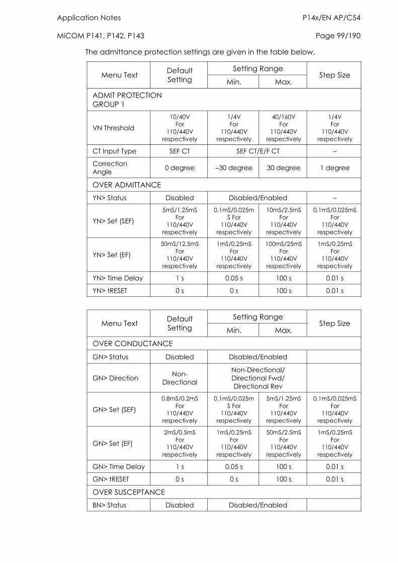
Application Notes P14x/EN AP/C54 MiCOM P141, P142, P143 Page 99/190
The admittance protection settings are given in the table below.
Setting Range Menu Text Default
Setting Min. Max. Step Size
ADMIT PROTECTION GROUP 1
VN Threshold 10/40V
For 110/440V
respectively
1/4V For
110/440V respectively
40/160V For
110/440V respectively
1/4V For
110/440V respectively
CT Input Type SEF CT SEF CT/E/F CT –
Correction Angle 0 degree –30 degree 30 degree 1 degree
OVER ADMITTANCE
YN> Status Disabled Disabled/Enabled –
YN> Set (SEF) 5mS/1.25mS
For 110/440V
respectively
0.1mS/0.025mS For
110/440V respectively
10mS/2.5mS For
110/440V respectively
0.1mS/0.025mSFor
110/440V respectively
YN> Set (EF) 50mS/12.5mS
For 110/440V
respectively
1mS/0.25mS For
110/440V respectively
100mS/25mS For
110/440V respectively
1mS/0.25mS For
110/440V respectively
YN> Time Delay 1 s 0.05 s 100 s 0.01 s
YN> tRESET 0 s 0 s 100 s 0.01 s
Setting Range Menu Text Default
Setting Min. Max. Step Size
OVER CONDUCTANCE
GN> Status Disabled Disabled/Enabled
GN> Direction Non-Directional
Non-Directional/ Directional Fwd/ Directional Rev
GN> Set (SEF) 0.8mS/0.2mS
For 110/440V
respectively
0.1mS/0.025mS For
110/440V respectively
5mS/1.25mS For
110/440V respectively
0.1mS/0.025mS For
110/440V respectively
GN> Set (EF) 2mS/0.5mS
For 110/440V
respectively
1mS/0.25mS For
110/440V respectively
50mS/2.5mS For
110/440V respectively
1mS/0.25mS For
110/440V respectively
GN> Time Delay 1 s 0.05 s 100 s 0.01 s
GN> tRESET 0 s 0 s 100 s 0.01 s
OVER SUSCEPTANCE
BN> Status Disabled Disabled/Enabled
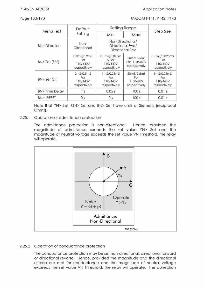
P14x/EN AP/C54 Application Notes Page 100/190 MiCOM P141, P142, P143
Setting Range Menu Text Default
Setting Min. Max. Step Size
BN> Direction Non-Directional
Non-Directional/ Directional Fwd/ Directional Rev
BN> Set (SEF) 0.8mS/0.2mS
For 110/440V
respectively
0.1mS/0.025mS For
110/440V respectively
5mS/1.25mS For 110/440V respectively
0.1mS/0.025mS For
110/440V respectively
BN> Set (EF) 2mS/0.5mS
For 110/440V
respectively
1mS/0.25mS For
110/440V respectively
50mS/2.5mS For
110/440V respectively
1mS/0.25mS For
110/440V respectively
BN> Time Delay 1 s 0.05 s 100 s 0.01 s
BN> tRESET 0 s 0 s 100 s 0.01 s
Note that YN> Set, GN> Set and BN> Set have units of Siemens (reciprocal Ohms).
2.25.1 Operation of admittance protection
The admittance protection is non-directional. Hence, provided the magnitude of admittance exceeds the set value YN> Set and the magnitude of neutral voltage exceeds the set value VN Threshold, the relay will operate.
2.25.2 Operation of conductance protection
The conductance protection may be set non-directional, directional forward or directional reverse. Hence, provided the magnitude and the directional criteria are met for conductance and the magnitude of neutral voltage exceeds the set value VN Threshold, the relay will operate. The correction
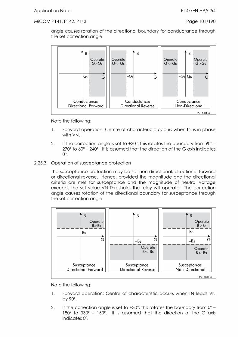
Application Notes P14x/EN AP/C54 MiCOM P141, P142, P143 Page 101/190
angle causes rotation of the directional boundary for conductance through the set correction angle.
Note the following:
1. Forward operation: Centre of characteristic occurs when N is in phase with VN.
2. If the correction angle is set to +30º, this rotates the boundary from 90º – 270º to 60º – 240º. It is assumed that the direction of the G axis indicates 0º.
2.25.3 Operation of susceptance protection
The susceptance protection may be set non-directional, directional forward or directional reverse. Hence, provided the magnitude and the directional criteria are met for susceptance and the magnitude of neutral voltage exceeds the set value VN Threshold, the relay will operate. The correction angle causes rotation of the directional boundary for susceptance through the set correction angle.
Note the following:
1. Forward operation: Centre of characteristic occurs when N leads VN by 90º.
2. If the correction angle is set to +30º, this rotates the boundary from 0º – 180º to 330º – 150º. It is assumed that the direction of the G axis indicates 0º.
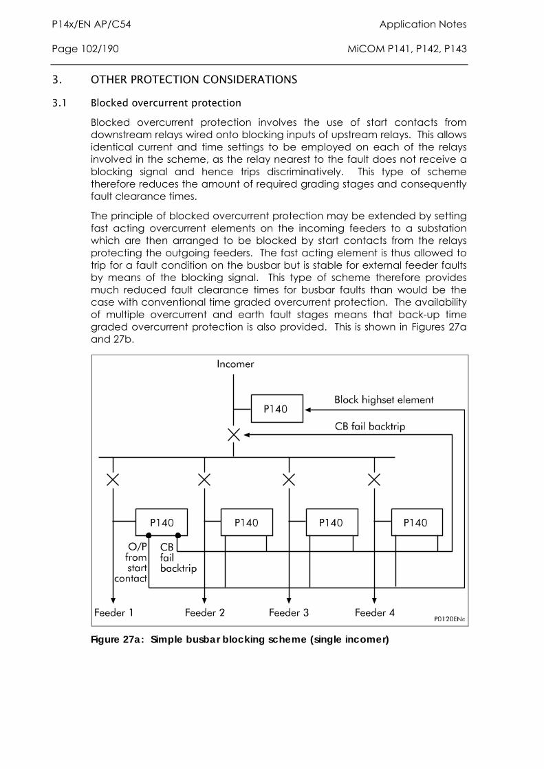
P14x/EN AP/C54 Application Notes Page 102/190 MiCOM P141, P142, P143
3. OTHER PROTECTION CONSIDERATIONS
3.1 Blocked overcurrent protection Blocked overcurrent protection involves the use of start contacts from downstream relays wired onto blocking inputs of upstream relays. This allows identical current and time settings to be employed on each of the relays involved in the scheme, as the relay nearest to the fault does not receive a blocking signal and hence trips discriminatively. This type of scheme therefore reduces the amount of required grading stages and consequently fault clearance times.
The principle of blocked overcurrent protection may be extended by setting fast acting overcurrent elements on the incoming feeders to a substation which are then arranged to be blocked by start contacts from the relays protecting the outgoing feeders. The fast acting element is thus allowed to trip for a fault condition on the busbar but is stable for external feeder faults by means of the blocking signal. This type of scheme therefore provides much reduced fault clearance times for busbar faults than would be the case with conventional time graded overcurrent protection. The availability of multiple overcurrent and earth fault stages means that back-up time graded overcurrent protection is also provided. This is shown in Figures 27a and 27b.
Figure 27a: Simple busbar blocking scheme (single incomer)
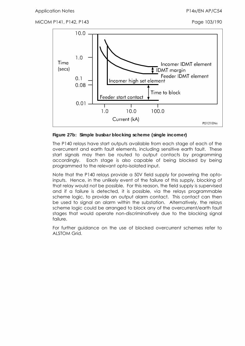
Application Notes P14x/EN AP/C54 MiCOM P141, P142, P143 Page 103/190
Figure 27b: Simple busbar blocking scheme (single incomer)
The P140 relays have start outputs available from each stage of each of the overcurrent and earth fault elements, including sensitive earth fault. These start signals may then be routed to output contacts by programming accordingly. Each stage is also capable of being blocked by being programmed to the relevant opto-isolated input.
Note that the P140 relays provide a 50V field supply for powering the opto-inputs. Hence, in the unlikely event of the failure of this supply, blocking of that relay would not be possible. For this reason, the field supply is supervised and if a failure is detected, it is possible, via the relays programmable scheme logic, to provide an output alarm contact. This contact can then be used to signal an alarm within the substation. Alternatively, the relays scheme logic could be arranged to block any of the overcurrent/earth fault stages that would operate non-discriminatively due to the blocking signal failure.
For further guidance on the use of blocked overcurrent schemes refer to ALSTOM Grid.
P14x/EN AP/C54 Application Notes Page 104/190 MiCOM P141, P142, P143
4. APPLICATION OF NON PROTECTION FUNCTIONS
4.1 Three phase auto-reclosing An analysis of faults on any overhead line network has shown that 80 – 90% are transient in nature.
A transient fault, such as an insulator flash-over, is a self clearing ‘non-damage’ fault. This type of fault can be cleared by the immediate tripping of one or more circuit breakers to isolate the fault, and does not recur when the line is re-energised. Lightning is the most common cause of transient faults, other possible causes being clashing conductors and wind blown debris. The remaining 10 – 20% of faults are either semi-permanent or permanent.
A semi-permanent fault could be caused by a small tree branch falling on the line. Here the cause of the fault would not be removed by the immediate tripping of the circuit, but could be burnt away during a time delayed trip.
Permanent faults could be broken conductors, transformer faults, cable faults or machine faults which must be located and repaired before the supply can be restored.
In the majority of fault incidents, if the faulty line is immediately tripped out, and time is allowed for the fault arc to de-ionise, reclosure of the circuit breakers will result in the line being successfully re-energised. Autoreclose schemes are employed to automatically reclose a switching device a set time after it has been opened due to operation of protection where transient and semi-permanent faults are prevalent.
On HV/MV distribution networks, auto-reclosing is applied mainly to radial feeders where system stability problems do not generally arise. The main advantages to be derived from using autoreclose can be summarised as follows:
Minimises interruptions in supply to the consumer.
Reduces operating costs - less man hours in repairing fault damage and the possibility of running substations unattended. With autoreclose instantaneous protection can be used which means shorter fault duration’s which gives rise to less fault damage and fewer permanent faults.
As 80% of overhead line faults are transient, elimination of loss of supply from such faults, by the introduction of autoreclosing, gives obvious benefits. Furthermore, autoreclosing may allow a particular substation to be run unattended. In the case of unattended substations, the number of visits by personnel to reclose a circuit breaker manually after a fault can be substantially reduced, an important consideration for substations in remote areas.
The introduction of autoreclosing gives an important benefit on circuits using time graded protection, in that it allows the use of instantaneous protection to give a high speed first trip. With fast tripping, the duration of the power arc resulting from an overhead line fault is reduced to a minimum, thus lessening the chance of damage to the line, which might otherwise cause a
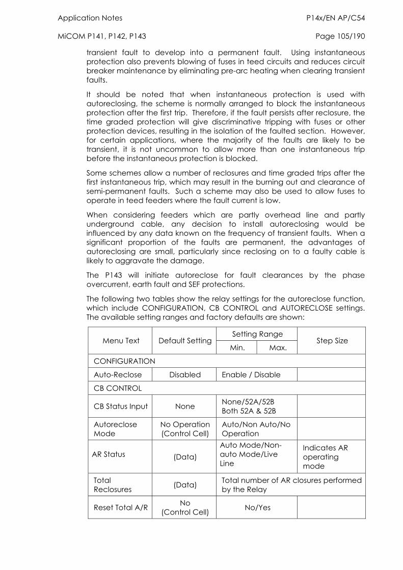
Application Notes P14x/EN AP/C54 MiCOM P141, P142, P143 Page 105/190
transient fault to develop into a permanent fault. Using instantaneous protection also prevents blowing of fuses in teed circuits and reduces circuit breaker maintenance by eliminating pre-arc heating when clearing transient faults.
It should be noted that when instantaneous protection is used with autoreclosing, the scheme is normally arranged to block the instantaneous protection after the first trip. Therefore, if the fault persists after reclosure, the time graded protection will give discriminative tripping with fuses or other protection devices, resulting in the isolation of the faulted section. However, for certain applications, where the majority of the faults are likely to be transient, it is not uncommon to allow more than one instantaneous trip before the instantaneous protection is blocked.
Some schemes allow a number of reclosures and time graded trips after the first instantaneous trip, which may result in the burning out and clearance of semi-permanent faults. Such a scheme may also be used to allow fuses to operate in teed feeders where the fault current is low.
When considering feeders which are partly overhead line and partly underground cable, any decision to install autoreclosing would be influenced by any data known on the frequency of transient faults. When a significant proportion of the faults are permanent, the advantages of autoreclosing are small, particularly since reclosing on to a faulty cable is likely to aggravate the damage.
The P143 will initiate autoreclose for fault clearances by the phase overcurrent, earth fault and SEF protections.
The following two tables show the relay settings for the autoreclose function, which include CONFIGURATION, CB CONTROL and AUTORECLOSE settings. The available setting ranges and factory defaults are shown:
Setting Range Menu Text Default Setting
Min. Max. Step Size
CONFIGURATION
Auto-Reclose Disabled Enable / Disable
CB CONTROL
CB Status Input None None/52A/52B Both 52A & 52B
Autoreclose Mode
No Operation (Control Cell)
Auto/Non Auto/No Operation
AR Status (Data) Auto Mode/Non-auto Mode/Live Line
Indicates AR operating mode
Total Reclosures (Data) Total number of AR closures performed
by the Relay
Reset Total A/R No (Control Cell) No/Yes
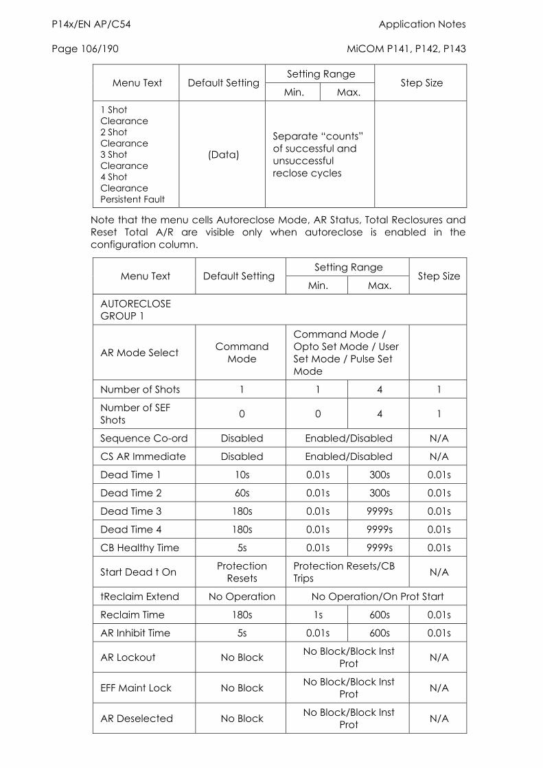
P14x/EN AP/C54 Application Notes Page 106/190 MiCOM P141, P142, P143
Setting Range Menu Text Default Setting
Min. Max. Step Size
1 Shot Clearance 2 Shot Clearance 3 Shot Clearance 4 Shot Clearance Persistent Fault
(Data)
Separate “counts” of successful and unsuccessful reclose cycles
Note that the menu cells Autoreclose Mode, AR Status, Total Reclosures and Reset Total A/R are visible only when autoreclose is enabled in the configuration column.
Setting Range Menu Text Default Setting
Min. Max. Step Size
AUTORECLOSE GROUP 1
AR Mode Select Command Mode
Command Mode / Opto Set Mode / User Set Mode / Pulse Set Mode
Number of Shots 1 1 4 1
Number of SEF Shots 0 0 4 1
Sequence Co-ord Disabled Enabled/Disabled N/A
CS AR Immediate Disabled Enabled/Disabled N/A
Dead Time 1 10s 0.01s 300s 0.01s
Dead Time 2 60s 0.01s 300s 0.01s
Dead Time 3 180s 0.01s 9999s 0.01s
Dead Time 4 180s 0.01s 9999s 0.01s
CB Healthy Time 5s 0.01s 9999s 0.01s
Start Dead t On Protection Resets
Protection Resets/CB Trips N/A
tReclaim Extend No Operation No Operation/On Prot Start
Reclaim Time 180s 1s 600s 0.01s
AR Inhibit Time 5s 0.01s 600s 0.01s
AR Lockout No Block No Block/Block Inst Prot N/A
EFF Maint Lock No Block No Block/Block Inst Prot N/A
AR Deselected No Block No Block/Block Inst Prot N/A
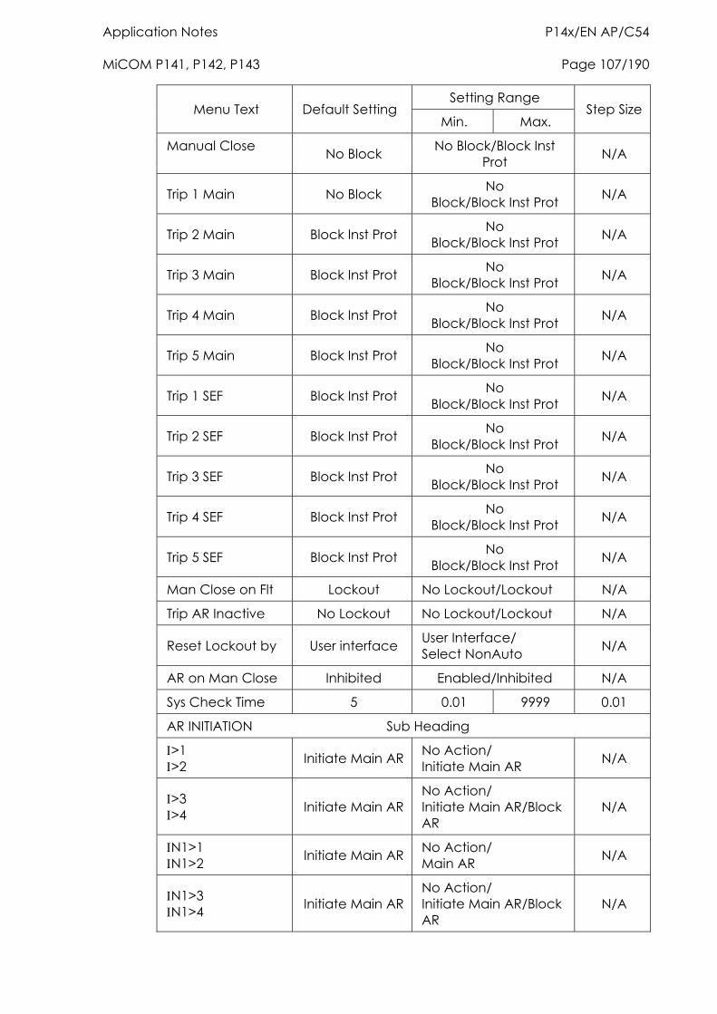
Application Notes P14x/EN AP/C54 MiCOM P141, P142, P143 Page 107/190
Setting Range Menu Text Default Setting
Min. Max. Step Size
Manual Close No Block No Block/Block Inst
Prot N/A
Trip 1 Main No Block No Block/Block Inst Prot N/A
Trip 2 Main Block Inst Prot No Block/Block Inst Prot N/A
Trip 3 Main Block Inst Prot No Block/Block Inst Prot N/A
Trip 4 Main Block Inst Prot No Block/Block Inst Prot N/A
Trip 5 Main Block Inst Prot No Block/Block Inst Prot N/A
Trip 1 SEF Block Inst Prot No Block/Block Inst Prot N/A
Trip 2 SEF Block Inst Prot No Block/Block Inst Prot N/A
Trip 3 SEF Block Inst Prot No Block/Block Inst Prot N/A
Trip 4 SEF Block Inst Prot No Block/Block Inst Prot N/A
Trip 5 SEF Block Inst Prot No Block/Block Inst Prot N/A
Man Close on Flt Lockout No Lockout/Lockout N/A
Trip AR Inactive No Lockout No Lockout/Lockout N/A
Reset Lockout by User interface User Interface/ Select NonAuto N/A
AR on Man Close Inhibited Enabled/Inhibited N/A
Sys Check Time 5 0.01 9999 0.01
AR INITIATION Sub Heading
>1 >2 Initiate Main AR No Action/
Initiate Main AR N/A
>3 >4 Initiate Main AR
No Action/ Initiate Main AR/Block AR
N/A
N1>1 N1>2 Initiate Main AR No Action/
Main AR N/A
N1>3 N1>4 Initiate Main AR
No Action/ Initiate Main AR/Block AR
N/A
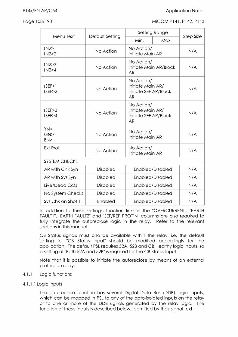
P14x/EN AP/C54 Application Notes Page 108/190 MiCOM P141, P142, P143
Setting Range Menu Text Default Setting
Min. Max. Step Size
N2>1 N2>2 No Action No Action/
Initiate Main AR N/A
N2>3 N2>4 No Action
No Action/ Initiate Main AR/Block AR
N/A
SEF>1 SEF>2 No Action
No Action/ Initiate Main AR/ Initiate SEF AR/Block AR
N/A
SEF>3 SEF>4 No Action
No Action/ Initiate Main AR/ Initiate SEF AR/Block AR
N/A
YN> GN> BN>
No Action No Action/ Initiate Main AR N/A
Ext Prot No Action No Action/
Initiate Main AR N/A
SYSTEM CHECKS
AR with Chk Syn Disabled Enabled/Disabled N/A
AR with Sys Syn Disabled Enabled/Disabled N/A
Live/Dead Ccts Disabled Enabled/Disabled N/A
No System Checks Disabled Enabled/Disabled N/A
Sys Chk on Shot 1 Enabled Enabled/Disabled N/A
In addition to these settings, function links in the "OVERCURRENT", "EARTH FAULT1", "EARTH FAULT2" and "SEF/REF PROT’N" columns are also required to fully integrate the autoreclose logic in the relay. Refer to the relevant sections in this manual.
CB Status signals must also be available within the relay, i.e. the default setting for "CB Status Input" should be modified accordingly for the application. The default PSL requires 52A, 52B and CB Healthy logic inputs, so a setting of "Both 52A and 52B" is required for the CB Status Input.
Note that it is possible to initiate the autoreclose by means of an external protection relay.
4.1.1 Logic functions
4.1.1.1 Logic inputs
The autoreclose function has several Digital Data Bus (DDB) logic inputs, which can be mapped in PSL to any of the opto-isolated inputs on the relay or to one or more of the DDB signals generated by the relay logic. The function of these inputs is described below, identified by their signal text.
Application Notes P14x/EN AP/C54 MiCOM P141, P142, P143 Page 109/190
4.1.1.1.1 CB healthy
The majority of circuit breakers are only capable of providing one trip-close-trip cycle. Following this, it is necessary to re-establish if there is sufficient energy in the circuit breaker (spring charged, gas pressure healthy, etc.) before the CB can be reclosed. The "DDB 230: CB Healthy" input is used to ensure that there is sufficient energy available to close and trip the CB before initiating a CB close command. If on completion of the dead time, the "DDB 230: CB Healthy" input is low, and remains low for a period given by the "CB Healthy Time" timer, lockout will result and the CB will remain open.
This check can be disabled by not allocating an opto input for "DDB 230: CB Healthy". The signal defaults to high if no logic is mapped to DDB 230 within the PSL in the relay.
4.1.1.1.2 BAR
The "DDB 239: Block AR" input will block autoreclose and cause a lockout if autoreclose is in progress. It can be used when protection operation without autoreclose is required. A typical example is on a transformer feeder, where autoreclosing may be initiated from the feeder protection but blocked from the transformer protection.
4.1.1.1.3 Reset lockout
The "DDB 237: Reset Lockout" input can be used to reset the autoreclose function following lockout and reset any autoreclose alarms, provided that the signals which initiated the lockout have been removed.
4.1.1.1.4 Auto mode
The "DDB 241: Auto Mode" input is used to select the Auto operating mode; autoreclose in service. When the "DDB 241: Auto Mode", "DDB 240: Live Line Mode" and "DDB 242: Telecontrol" inputs are off the "Non Auto Mode" of operation is selected; autoreclose out of service.
4.1.1.1.5 Live line mode
The "DDB 240: Live Line Mode" input is used to select the Live Line operating mode where autoreclose is out of service and all blocking of instantaneous protection by autoreclose is disabled. This operating mode takes precedence over all other operating modes for safety reasons.
4.1.1.1.6 Telecontrol mode
The "DDB 242: Telecontrol" input is used to select the Telecontrol operating mode whereby the Auto and Non Auto modes of operation can be selected remotely.
4.1.1.1.7 Live/Dead Ccts OK
DDB 461: “Live/Dead Ccts OK” is an input to the autoreclose logic. When AR is enabled with one or both sides of the CB dead (AUTORECLOSE GROUP 1 – SYSTEM CHECKS setting 49 43 – Live/Dead Ccts: Enabled), DDB 461 should be mapped in PSL to appropriate combinations of Live Line, Dead Line, Live Bus and Dead Bus signals from the system check logic (DDB 443, 444, 445 & 446), as required for the specific application. If setting 49 43 is Disabled, DDB 461 mapping is irrelevant.
P14x/EN AP/C54 Application Notes Page 110/190 MiCOM P141, P142, P143
4.1.1.1.8 AR SysChecks OK
DDB 403: “AR SysChecks OK” can be mapped in PSL from system checks output DDB 449: “SysChks Inactive”, to enable autoreclosing without any system checks, if the system check function is disabled (CONFIGURATION setting 09 23 – System Checks: Disabled). This mapping is not essential, because AUTORECLOSE GROUP 1 – SYSTEM CHECKS setting 49 44 – No System Checks can be set to Enabled to achieve the same effect.
DDB 403 can also be mapped to an opto input, to enable the P142 or P143 to receive a signal from an external system monitoring relay to indicate that system conditions are suitable for CB closing. This should not normally be necessary, since the P143 has comprehensive built in system check functionality. However, it might be used if a P142, which does not have internal synchro check capability, is required to work in conjunction with a separate synchronism check relay.
4.1.1.1.9 Ext AR Prot trip/start
DDB 439: “Ext AR Prot Trip” and/or DDB 440: “Ext AR Prot Start” allow initiation of autoreclosing by a separate protection relay. Please refer to section 4.1.3.2 – Autoreclose Initiation.
4.1.1.1.10 DAR complete
At least one major utility, which uses delayed autoreclosing (DAR) on most of its transmission network, requires a “DAR in Progress” signal from AR initiation up to the application of the CB Close command, but not during the reclaim time following CB reclosure. DDB 453: “DAR Complete” can, if required, be mapped in PSL to be activated for a short pulse when a CB Close command is given at the end of the dead time. If DDB 453: “DAR Complete” is activated during an autoreclose cycle, output DDB 456: “AR in Progress 1” resets, even though the reclaim time may still be running and DDB 360: “AR in Progress” remains set until the end of the reclaim time. For most applications, DDB 453 can be ignored, i.e. not mapped in PSL; in such cases, output DDB 456: AR in Progress 1 operates and resets in parallel with DDB 360: AR in Progress.
4.1.1.1.11 CB in service
One of the interlocks in the autoreclose initiation logic is DDB 454: “CB in Service”. This input must be high until the instant of protection operation for an autoreclose cycle to be initiated. For most applications, this DDB can be mapped simply from the “CB Closed” DDB 379. More complex PSL mapping can be programmed if required, e.g. where it is necessary to confirm not only that the CB is closed but also that the line and/or bus VT is actually live up to the instant of protection operation.
4.1.1.1.12 AR restart
In a very small number of applications, it is sometimes necessary to initiate an autoreclose cycle via an external signal to an opto input when the normal interlock conditions are not all satisfied, i.e. the CB is open and the associated feeder is dead. If input DDB 455: “AR Restart” is mapped to an opto input, activation of that opto input will initiate an autoreclose cycle irrespective of the status of the “CB in Service” input, provided the other interlock conditions, such as AR enabled, are still satisfied.
Application Notes P14x/EN AP/C54 MiCOM P141, P142, P143 Page 111/190
4.1.1.1.13 DT OK to start
This is an optional extra interlock in the dead time initiation logic. In addition to the CB being open and the protection reset, DDB 458: “DT OK to Start” has to be high to enable the dead time function to be “primed” after an AR cycle has started. Once the dead time function is primed, DDB 458 has no further effect – the dead time function stays primed even if DDB 458 subsequently goes low. A typical PSL mapping for this input is from a “Dead Line” signal (DDB 444) from the system check logic, to enable dead time priming only when the feeder has gone dead after CB tripping. If this extra dead time priming interlock is not required, DDB 458 can be left unmapped, and will then default to high.
4.1.1.1.14 Dead time enabled
This is another optional interlock in the dead time logic. In addition to the CB open, protection reset and “dead time primed” signals, DDB 457: “Dead Time Enabled” has to be high to allow the dead time to run. If DDB 457 goes low, the dead time stops and resets, but stays primed, and will restart from zero when DDB 457 goes high again. A typical PSL mapping for DDB 457 is from the CB Healthy input DDB 230, or from selected Live Bus, Dead Line etc signals from the system check logic. It could also be mapped to an opto input to provide a “hold off” function for the follower CB in a “master/follower” application with 2 CBs. If this optional interlock is not required, DDB 457 can be left unmapped, and will then default to high.
4.1.1.1.15 AR Init trip test
If DDB 464: “AR Init Trip Test” is mapped to an opto input, and that input is activated momentarily, the relay logic generates a CB trip output via DDB 372, mapped in default PSL to output R3, and initiates an autoreclose cycle.
4.1.1.2 Autoreclose logic outputs
The following DDB signals can be assigned to a relay contact in the PSL or assigned to a Monitor Bit in "Commissioning Tests", to provide information about the status of the auto Reclose cycle. They can also be applied to other PSL logic as required. The logic output DDBs are described below, identified by their DDB signal text.
4.1.1.2.1 AR in progress
The "DDB 360: AR in Progress" signal is present during the complete reclose cycle from protection initiation to the end of the reclaim time or lockout. DDB 456: “AR in Progress 1” operates with DDB 360 at autoreclose initiation, and, if DDB 453: “DAR Complete” does not operate, remains operated until DDB 360 resets at the end of the cycle. If DDB 453 goes high during the autoreclose cycle, DDB 456 resets (see notes on logic input “DAR Complete” above).
4.1.1.2.2 Sequence counter status
During each autoreclose cycle, a “Sequence Counter” increments by 1 after each fault trip, and resets to zero at the end of the cycle.
DDB 362: “Seq Counter = 0” is set when the counter is at zero; DDB 363: “Seq Counter = 1” is set when the counter is at 1; DDB 364: “Seq Counter = 2” is set when the counter is at 2; DDB 365: “Seq Counter = 3” is set when the counter is at 3;
P14x/EN AP/C54 Application Notes Page 112/190 MiCOM P141, P142, P143
and DDB 366: “Seq Counter = 4” is set when the counter is at 4.
4.1.1.2.3 Successful close
The "DDB 367: Successful Close" output indicates that an autoreclose cycle has been successfully completed. A successful autoreclose signal is given after the CB has tripped from the protection and reclosed whereupon the fault has been cleared and the reclaim time has expired resetting the autoreclose cycle. The successful autoreclose output is reset at the next CB trip or from one of the reset lockout methods; see Section 4.1.3.8.1. ’Reset from lockout’.
4.1.1.2.4 AR in service
The "DDB 361: AR in service" output indicates whether the autoreclose is in or out of service. Autoreclose is in service when the relay is in Auto mode and out of service when in the Non Auto and Live Line modes.
4.1.1.2.5 Block main prot
The "DDB 358: Block Main Prot" output indicates that the instantaneous protection ">3", ">4", "N1>3", "N1>4", "N2>3", "N2>4" is being blocked by the autoreclose logic during the autoreclose cycle. Blocking of the instantaneous stages for each trip of the autoreclose cycle is programmed using the Overcurrent and Earth Fault 1/2 function link settings, "> Function Link", "N1> Func Link", "N2> Func Link", and the "Trip 1/2/3/4/5 Main" settings; see Section 4.1.3.3 ‘Blocking instantaneous protection during an autoreclose cycle’.
4.1.1.2.6 Block SEF prot
The "DDB 359: Block SEF Prot" output indicates that the instantaneous SEF protection "SEF>3, SEF>4" is being blocked by the autoreclose logic during the autoreclose cycle. Blocking of the instantaneous SEF stages for each trip of the autoreclose cycle is programmed using the SEF/REF Prot’n function link setting, "SEF> Func Link", and the "Trip 1/2/3/4/5 SEF" settings; see Section 4.1.3.3 ‘Blocking instantaneous protection during an autoreclose cycle’.
4.1.1.2.7 Reclose checks
DDB 460: “Reclose Checks” operates when the dead time function is “primed” (see notes on logic input “DT OK to Start”, above).
4.1.1.2.8 Dead T in prog
The "DDB 368: Dead T in Prog" output indicates that the dead time is in progress. This signal is set when DDB 460: “Reclose Checks” is set AND input DDB 457: “Dead Time Enabled” is high, and may be useful during relay commissioning to check the operation of the autoreclose cycle.
4.1.1.2.9 DT complete
DDB 459: “DT Complete” operates at the end of the set dead time, and remains operated until either the scheme resets at the end of the reclaim time or a further protection operation/AR initiation occurs. It can be applied purely as an indication, or included in PSL mapping to logic input DDB 453: “DAR Complete” if required (see logic input notes).
Application Notes P14x/EN AP/C54 MiCOM P141, P142, P143 Page 113/190
4.1.1.2.10 System checks indication
DDB 462: “AR Sync Check” operates when either of the synchro check modules, if selected for autoreclosing, confirms an “in synchronism” condition.
DDB 463: “AR SysChecks OK” operates when any selected system check condition (synchro check, live bus/dead line etc.) is confirmed.
4.1.1.2.11 Auto close
The "DDB 371: Auto Close" output indicates that the autoreclose logic has issued a close signal to the CB. This output feeds a signal to the control close pulse timer and remains on until the CB has closed. This signal may be useful during relay commissioning to check the operation of the autoreclose cycle.
4.1.1.2.12 “Trip when AR blocked” indication
DDB 369: “Protection Lockt” operates if AR lockout is triggered by protection operation either during the inhibit period following a manual CB close (see section 4.1.3.7 – “Autoreclose inhibit following manual close”), or when the relay is in Non Auto or Live Line mode (see section 4.1.3.8 – “AR lockout”).
4.1.1.2.13 Reset lockout indication
DDB 370: “Reset Lckout Alm” operates when the relay is in Non Auto mode, if setting 49 22 – “Reset Lockout by” – is set to “Select NonAuto”. See section 4.1.3.8.1 – ‘Reset from lockout’.
4.1.1.3 Autoreclose alarms
The following DDB signals will produce a relay alarm. These are described below, identified by their DDB signal text.
4.1.1.3.1 AR no checksync (latched)
The "DDB 165: AR No Checksync" alarm indicates that the system voltages were not suitable for autoreclosing at the end of the check synch window time (Sys Check Time), leading to a lockout condition. This alarm can be reset using one of the reset lockout methods; see Section 4.1.3.8.1 ’Reset from lockout’.
4.1.1.3.2 AR CB unhealthy (latched)
The "DDB 164: AR CB Unhealthy" alarm indicates that the "DDB 230: CB Healthy" input was not energised at the end of the "CB Healthy Time", leading to a lockout condition. The "DDB 230: CB Healthy" input is used to indicate that there is sufficient energy in the CB operating mechanism to close and trip the CB at the end of the dead time. This alarm can be reset using one of the reset lockout methods; see Section 4.1.3.8.1 ’Reset from lockout’.
4.1.1.3.3 AR lockout (self reset)
The "DDB 163: AR Lockout" alarm indicates that the relay is in a lockout status and that further reclose attempts will not be made; see Section 4.1.3.8 ‘AR Lockout’ for more details. This alarm can be reset using one of the reset lockout methods; see Section 4.1.3.8.1 ’Reset from lockout’.
P14x/EN AP/C54 Application Notes Page 114/190 MiCOM P141, P142, P143
4.1.2 Autoreclose logic operating sequence
The autoreclose function provides multi-shot three phase autoreclose control. It can be adjusted to perform a single shot, two shot, three shot or four shot cycle, selectable via "Number of Shots". There is also the option to initiate a separate autoreclose cycle with a different number of shots, "Number of SEF Shots", for the SEF protection. Dead times for all shots (reclose attempts) are independently adjustable. The number of shots is directly related to the type of faults likely to occur on the system and the voltage level of the system. Generally, on medium voltage networks where the percentage of transient and semi-permanent faults is likely to be high, a multi-shot autoreclose device will increase the possibility of the distribution line being successfully re-energised following reclosure of the circuit breaker. For more information, please refer to Section 4.1.4 ‘Setting guidelines’.
An autoreclose cycle can be internally initiated by operation of a protection element or externally by a separate protection device, provided the circuit breaker is closed until the instant of protection operation. The dead time "Dead Time 1", "Dead Time 2", "Dead Time 3", "Dead Time 4" starts when the circuit breaker has tripped and optionally when the protection has reset, selectable via "Start Dead t On". At the end of the relevant dead time, a CB close signal is given, provided system conditions are suitable. The system conditions to be met for closing are that the system voltages are in synchronism or dead line/live bus or live line/dead bus conditions exist, indicated by the internal check synchronising element and that the circuit breaker closing spring, or other energy source, is fully charged indicated from the "DDB 230: CB Healthy" input. The CB close signal is cut-off when the circuit breaker closes.
When the CB has closed the reclaim time "Reclaim Time" starts. If the circuit breaker does not trip again, the autoreclose function resets at the end of the reclaim time. If the protection operates during the reclaim time the relay either advances to the next shot in the programmed autoreclose cycle, or, if all programmed reclose attempts have been made, goes to lockout.
The total number of autoreclosures is shown in the CB Control menu under "Total Reclosures". This value can be reset to zero with the "Reset Total A/R" command.
4.1.3 Main operating features
4.1.3.1 Operation modes
The autoreclosing function has three operating modes:
1. AUTO MODE Autoreclose in service
2. NON AUTO MODE Autoreclose out of service – selected protection
functions are blocked if setting “AR Deselected” [4914] = Block Inst Prot.
3. LIVE LINE MODE Autoreclose out of service – protection functions are NOT blocked, even if setting “AR Deselected” [4914] = Block Inst Prot. LIVE LINE MODE is a functional requirement by some utilities, for
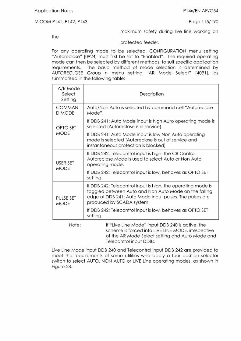
Application Notes P14x/EN AP/C54 MiCOM P141, P142, P143 Page 115/190
maximum safety during live line working on the protected feeder.
For any operating mode to be selected, CONFIGURATION menu setting “Autoreclose” [0924] must first be set to “Enabled”. The required operating mode can then be selected by different methods, to suit specific application requirements. The basic method of mode selection is determined by AUTORECLOSE Group n menu setting “AR Mode Select” [4091], as summarised in the following table:
A/R Mode Select Setting
Description
COMMAND MODE
Auto/Non Auto is selected by command cell “Autoreclose Mode”.
OPTO SET MODE
If DDB 241: Auto Mode input is high Auto operating mode is selected (Autoreclose is in service).
If DDB 241: Auto Mode input is low Non Auto operating mode is selected (Autoreclose is out of service and instantaneous protection is blocked)
USER SET MODE
If DDB 242: Telecontrol input is high, the CB Control Autoreclose Mode is used to select Auto or Non Auto operating mode.
If DDB 242: Telecontrol input is low, behaves as OPTO SET setting.
PULSE SET MODE
If DDB 242: Telecontrol input is high, the operating mode is toggled between Auto and Non Auto Mode on the falling edge of DDB 241: Auto Mode input pulses. The pulses are produced by SCADA system.
If DDB 242: Telecontrol input is low, behaves as OPTO SET setting.
Note: If “Live Line Mode” input DDB 240 is active, the scheme is forced into LIVE LINE MODE, irrespective of the AR Mode Select setting and Auto Mode and Telecontrol input DDBs.
Live Line Mode input DDB 240 and Telecontrol input DDB 242 are provided to meet the requirements of some utilities who apply a four position selector switch to select AUTO, NON AUTO or LIVE Line operating modes, as shown in Figure 28.
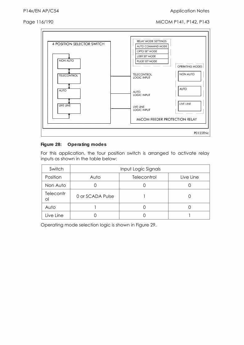
P14x/EN AP/C54 Application Notes Page 116/190 MiCOM P141, P142, P143
Figure 28: Operating modes
For this application, the four position switch is arranged to activate relay inputs as shown in the table below:
Switch Input Logic Signals
Position Auto Telecontrol Live Line
Non Auto 0 0 0
Telecontrol 0 or SCADA Pulse 1 0
Auto 1 0 0
Live Line 0 0 1
Operating mode selection logic is shown in Figure 29.
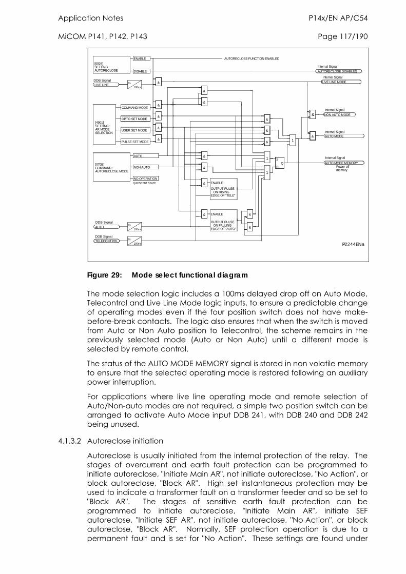
Application Notes P14x/EN AP/C54 MiCOM P141, P142, P143 Page 117/190
P2244ENa
AUTORECLOSE FUNCTION ENABLED
OUTPUT PULSE ON RISINGEDGE OF "TELE"
OUTPUT PULSE ON FALLINGEDGE OF "AUTO"
NO OPERATIONQUIESCENT STATE
TELECONTROL
AUTO
DDB Signal
DDB Signal0s
0s
100ms
100ms
[070B]COMMAND :AUTORECLOSE MODE
NON AUTO
AUTO
ENABLE&
& ENABLE
&
&
[4901]SETTING :AR MODESELECTION
USER SET MODE
PULSE SET MODE
COMMAND MODE
OPTO SET MODE
[0924]SETTING :AUTORECLOSE
LIVE LINEDDB Signal
0s
100ms
ENABLE
DISABLE
&
&
&
&
&
&
&
&
&
1
1
S
RQ AUTO MODE MEMORY
Power offmemory
Internal Signal
&
&
& 1
NON AUTO MODE
AUTO MODEInternal Signal
Internal Signal
&
&
LIVE LINE MODE
AUTORECLOSE DISABLED
Internal Signal
Internal Signal
Figure 29: Mode select functional diagram
The mode selection logic includes a 100ms delayed drop off on Auto Mode, Telecontrol and Live Line Mode logic inputs, to ensure a predictable change of operating modes even if the four position switch does not have make-before-break contacts. The logic also ensures that when the switch is moved from Auto or Non Auto position to Telecontrol, the scheme remains in the previously selected mode (Auto or Non Auto) until a different mode is selected by remote control.
The status of the AUTO MODE MEMORY signal is stored in non volatile memory to ensure that the selected operating mode is restored following an auxiliary power interruption.
For applications where live line operating mode and remote selection of Auto/Non-auto modes are not required, a simple two position switch can be arranged to activate Auto Mode input DDB 241, with DDB 240 and DDB 242 being unused.
4.1.3.2 Autoreclose initiation
Autoreclose is usually initiated from the internal protection of the relay. The stages of overcurrent and earth fault protection can be programmed to initiate autoreclose, "Initiate Main AR", not initiate autoreclose, "No Action", or block autoreclose, "Block AR". High set instantaneous protection may be used to indicate a transformer fault on a transformer feeder and so be set to "Block AR". The stages of sensitive earth fault protection can be programmed to initiate autoreclose, "Initiate Main AR", initiate SEF autoreclose, "Initiate SEF AR", not initiate autoreclose, "No Action", or block autoreclose, "Block AR". Normally, SEF protection operation is due to a permanent fault and is set for "No Action". These settings are found under
P14x/EN AP/C54 Application Notes Page 118/190 MiCOM P141, P142, P143
the "AR INITIATION" settings. For example if ">1" is set to "Initiate Main AR", operation of the ">1" protection stage will initiate autoreclose; if SEF>1 is set to "No Action", operation of the SEF>1 protection stage will lead to a CB trip but no reclose.
A selection must be made for each protection stage that is enabled.
Autoreclose may also be externally initiated by a separate protection device. In this case, the following DDB signals should be mapped to logic inputs:
DDB 439: Ext AR Prot Trip
DDB 440: Ext AR Prot Start (if appropriate)
The setting EXT PROT should be set to "Initiate Main AR".
The autoreclose can be initiated from a protection start, when sequence co-ordination is required, and from a protection trip. Figure 1 of section P14x/EN LG illustrates how the start signal is generated and Figure 2, of the same section, demonstrates how the protection trip signal is produced. Figure 2 also shows how the block autoreclose is performed together with external AR initiation. Autoreclose blocking is discussed in detail in section 4.1.3.8.
Although a protection start and a protection trip can initiate an AR cycle, several checks still have to be performed before the initiate signal is given. Some of the checks are listed below:
Auto mode has been selected (AR in service)
Live Line mode is disabled
The number of main protection and SEF shots have not been reached (“Man High Shots” and SEF “High Shots” Signals see Figure 14 of section P14x/EN LG).
Sequence co-ordination enabled (required only for protection start to initiate AR; not necessary for protection trip)
CB lockout not set
CB “In Service” (DDB 454 is high)
Figure 3 of section P14x/EN LG illustrates how the autoreclose is initiated.
4.1.3.3 Blocking instantaneous protection during an AR cycle
Instantaneous protection may be blocked or not blocked for each trip in an autoreclose cycle. This is selected using the "Trip 1/2/3/4/5 Main" and "Trip 1/2/3/4/5 SEF" settings. These allow the Instantaneous elements of phase, earth fault and SEF protection to be selectively blocked for a CB trip sequence. For example, if "Trip 1 Main" is set to "No Block" and "Trip 2 Main" is set to "Block Inst Prot", the instantaneous elements of the phase and earth fault protection will be available for the first trip but blocked afterwards for the second trip during the autoreclose cycle. This is clearly illustrated in Figure 4 of section P14x/EN LG.
Instantaneous protection can also be blocked when the CB maintenance lockout counter or excessive fault frequency lockout has reached its penultimate value. For example, if "No. CB Ops Lock" is set to 100 and the "CB Operations = 99", the instantaneous protection can be blocked to ensure
Application Notes P14x/EN AP/C54 MiCOM P141, P142, P143 Page 119/190
that the last CB trip before lockout will be due to discriminative protection operation.
This is controlled using the "EFF Maint Lock" setting, if this is set to "Block Inst Prot" the instantaneous protection will be blocked for the last CB Trip before lockout occurs.
Instantaneous protection can also be blocked when the relay is locked out, using the "A/R Lockout" setting, "No Block/Block Inst Prot". It can also be blocked after a manual close using the "Manual Close" setting, "No Block/Block Inst Prot" or when the relay is in the Non Auto mode using the "A/R Deselected" setting "No Block/Block Inst Prot". The logic for these features, is shown in Figure 5 of section P14x/EN LG.
Note: The instantaneous protection stages must be identified in the Overcurrent, Earth Fault1, Earth Fault2 and SEF/REF Protn function link settings, "> Blocking", "N1> Blocking", "N2> Blocking" and "SEF> Blocking" respectively.
External protection may be blocked by mapping DDB 358 "Block Main Prot" or DDB 359 "Block SEF Prot" to appropriate output relay contacts.
4.1.3.4 Dead time control
Dead time is “primed” (DDB 460 – Reclose Checks – set) when:
the CB has tripped, and
(optionally via setting “Start Dead t On”), the protection has reset, and
DDB 458 – DT OK to Start – goes high.
Dead time remains “primed” until the protection re-operates, or the scheme resets at the end of the autoreclose cycle.
Once primed, the dead timer starts to run when DDB 457 – Dead Time Enabled is high.
Setting “CS AR Immediate” Enabled allows immediate re-closure of the circuit breaker provided both sides of the circuit breaker are live and in synchronism at any time after the dead time has started. This allows for quicker load restoration, as it is not necessary to wait for the full dead time.
If “CS AR Immediate” is disabled, or Line and Bus volts are not both live, the dead timer will continue to run, assuming the “DDB#457: Dead Time Enabled” (mapped in PSL) is asserted high. The “Dead Time Enabled” function could be mapped to an opto input to indicate that the circuit breaker is healthy i.e. spring charged etc. Mapping the “Dead Time Enabled” function in PSL increases the flexibility by allowing it, if necessary, to be triggered by other conditions such as “Live Line/Dead Bus” for example. If “Dead Time Enabled” is not mapped in PSL, it defaults to high, so the dead time can run.
The dead time control logic is illustrated in section P14x/EN LG.
Once the dead time is completed or a synchronism check is confirmed, the “Auto-close” signal is given, provided both the “CB Healthy” and the “System Checks” are satisfied. (see section 4.1.3.5 “System Checks”). The “Auto-close” signal triggers a “CB Close” command via the CB Control functionality (see section 4.10).
P14x/EN AP/C54 Application Notes Page 120/190 MiCOM P141, P142, P143
The “AR CB Close Control” Logic is illustrated in Figure 7 of section P14x/EN LG.
4.1.3.5 System checks
The permission to initiate an autoreclose depends upon the following System Check settings:
Live/Dead Ccts – When enabled this setting will give an “AR Check Ok” signal when the “DDB#461 Circuits OK” is asserted high. This logic input DDB would normally be mapped in PSL to appropriate combinations of Line Live, Line Dead, Bus Live and Bus Dead DDB signals. Autoreclose can be initiated once DDB 461 is asserted high.
No System Checks - When enabled this setting completely disables system checks thus allowing autoreclose initiation.
Sys Chk on Shot 1 - Can be used to disable system checks on first AR shot.
AR with Chk Syn (P143 only) - Only allows autoreclose when the system satisfies the “Check Synch Stage 1” settings (SYSTEM CHECKS menu).
AR with Sys Syn (P143 only) - Only allows autoreclose when the system satisfies the “Check Synch Stage 2” settings (SYSTEM CHECKS menu)
The “SYSTEM CHECKS” logic can be found in Figure 8 of section P14x/EN LG.
4.1.3.6 Reclaim timer initiation
The “tReclaim Extend” setting allows the user to control whether the timer is suspended from the protection start contacts or not. When a setting of “No Operation” is used the Reclaim Timer will operate from the instant that the CB is closed and will continue until the timer expires. The "Reclaim Time" must, therefore, be set in excess of the time delayed protection operating time to ensure that the protection can operate before the autoreclose function is reset. If the autoreclose function resets before the time delayed protection has operated instantaneous protection could be re-enabled and discriminating tripping lost.
For certain applications it is advantageous to set “tReclaim Extend” to “On Prot Start”. This facility allows the operation of the reclaim timer to be suspended after CB reclosure by a signal from the main protection start or SEF protection start signals. The main protection start signal is initiated from the start of any protection which has been selected to "Initiate Main AR" (initiate autoreclose) in the "AR Initiation" settings. The SEF protection start signal is initiated from the start of any SEF protection which has been selected to "Initiate SEF AR" (initiate SEF autoreclose) in the "AR Initiation" settings. This feature ensures that the reclaim time cannot time out and reset the autoreclose before the time delayed protection has operated. Since the Reclaim Timer will be suspended, it is unnecessary to use a timer setting in excess of the protection operating time, therefore a short reclaim time can be used. Short reclaim time settings can help to prevent unnecessary lockout for a succession of transient faults in a short period, for example during a thunderstorm. For more information, please refer to Section 4.1.4 ‘Setting guidelines’ or the Reclaim Timer logic in Figure 10 of section P14x/EN LG.
Application Notes P14x/EN AP/C54 MiCOM P141, P142, P143 Page 121/190
4.1.3.7 Autoreclose inhibit following manual close
To ensure that auto-reclosing is not initiated for a manual CB closure on to a pre-existing fault (switch on to fault), AUTO RECLOSE menu setting “A/R on Man Close” can be set to “Inhibited”. With this setting, autoreclose initiation is inhibited for a period equal to setting “A/R Inhibit Time” following a manual CB closure. The logic for A/R Inhibit is shown in Figure 15 of section P14x/EN LG. If a protection operation occurs during the inhibit period, auto-reclosing is not initiated. A further option is provided by setting “Man Close on Flt”; if this is set to “Lockout”, autoreclose is locked out (DDB#163: AR Lockout – see Section 4.1.1.3.3) for a fault during the inhibit period following manual CB closure. If “Man Close on Flt” is set to “No Lockout”, the CB trips without reclosure, but autoreclose is not locked out.
If it is required to block selected fast non-discriminating protection to obtain fully discriminative tripping during the AR initiation inhibit period following CB manual close, setting “Manual Close” can be set to “Block Inst Prot”. A “No Block” setting will enable all protection elements immediately on CB closure. (See also section 4.1.1.3.3).
If setting “A/R on Man Close” is set to “Enabled”, auto-reclosing can be initiated immediately on CB closure, and settings “A/R Inhibit Time”, “Man Close on Flt” and “Manual Close” are irrelevant.
Settings “A/R on Man Close”, “A/R Inhibit Time”, “Man Close on Flt” and “Manual Close” are all in the AUTO RECLOSE menu.
4.1.3.8 AR lockout
If protection operates during the reclaim time, following the final reclose attempt, the relay will be driven to lockout and the autoreclose function will be disabled until the lockout condition is reset. This will produce an alarm, "DDB 163: AR Lockout". The "DDB 239: Block AR" input will block autoreclose and cause a lockout if autoreclose is in progress.
Autoreclose lockout can also be caused by the CB failing to close because the CB springs are not charged/low gas pressure or there is no synchronism between the system voltages indicated by the "DDB 164: AR CB Unhealthy" and "DDB 165: AR No Checksync" alarms. The functionality, described above, is illustrated in the AR–Lockout logic diagram in Figure 11 of section P14x/EN LG.
AR lockout may also be due to a protection operation when the relay is in the Live Line or Non Auto modes when "Trip AR Inactive" is set to "Lockout". autoreclose lockout can also be caused by a protection operation after manual closing during the "AR Inhibit Time" when the "Manual Close on Flt" setting is set to Lockout. Figure 12 of section P14x/EN LG shows the logic associated with these functions.
Note: lockout can also be caused by the CB condition monitoring functions, maintenance lockout, excessive fault frequency lockout, broken current lockout, CB failed to trip, CB failed to close, manual close no check synchronism and CB unhealthy.
4.1.3.8.1 Reset from lockout
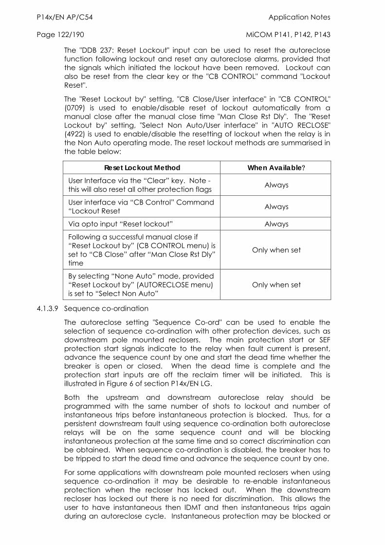
P14x/EN AP/C54 Application Notes Page 122/190 MiCOM P141, P142, P143
The "DDB 237: Reset Lockout" input can be used to reset the autoreclose function following lockout and reset any autoreclose alarms, provided that the signals which initiated the lockout have been removed. Lockout can also be reset from the clear key or the "CB CONTROL" command "Lockout Reset".
The "Reset Lockout by" setting, "CB Close/User interface" in "CB CONTROL" (0709) is used to enable/disable reset of lockout automatically from a manual close after the manual close time "Man Close Rst Dly". The "Reset Lockout by" setting, "Select Non Auto/User interface" in "AUTO RECLOSE" (4922) is used to enable/disable the resetting of lockout when the relay is in the Non Auto operating mode. The reset lockout methods are summarised in the table below:
Reset Lockout Method When Available
User Interface via the “Clear” key. Note - this will also reset all other protection flags Always
User interface via “CB Control” Command “Lockout Reset Always
Via opto input “Reset lockout” Always
Following a successful manual close if “Reset Lockout by” (CB CONTROL menu) is set to “CB Close” after “Man Close Rst Dly” time
Only when set
By selecting “None Auto” mode, provided “Reset Lockout by” (AUTORECLOSE menu) is set to “Select Non Auto”
Only when set
4.1.3.9 Sequence co-ordination
The autoreclose setting "Sequence Co-ord" can be used to enable the selection of sequence co-ordination with other protection devices, such as downstream pole mounted reclosers. The main protection start or SEF protection start signals indicate to the relay when fault current is present, advance the sequence count by one and start the dead time whether the breaker is open or closed. When the dead time is complete and the protection start inputs are off the reclaim timer will be initiated. This is illustrated in Figure 6 of section P14x/EN LG.
Both the upstream and downstream autoreclose relay should be programmed with the same number of shots to lockout and number of instantaneous trips before instantaneous protection is blocked. Thus, for a persistent downstream fault using sequence co-ordination both autoreclose relays will be on the same sequence count and will be blocking instantaneous protection at the same time and so correct discrimination can be obtained. When sequence co-ordination is disabled, the breaker has to be tripped to start the dead time and advance the sequence count by one.
For some applications with downstream pole mounted reclosers when using sequence co-ordination it may be desirable to re-enable instantaneous protection when the recloser has locked out. When the downstream recloser has locked out there is no need for discrimination. This allows the user to have instantaneous then IDMT and then instantaneous trips again during an autoreclose cycle. Instantaneous protection may be blocked or

Application Notes P14x/EN AP/C54 MiCOM P141, P142, P143 Page 123/190
not blocked for each trip in an autoreclose cycle using the " " "Trip 1/2/3/4/5 Main" and "Trip 1/2/3/4/5 SEF" settings, "Block Inst Prot/No Block".
4.1.3.10 Check synchronising for first reclose
The “Sys Chk on Shot 1”, (within SYSTEM CHECKS sub menu of AUTO-RECLOSE) setting is used to "Enable/Disable" system checks for the first reclose in an autoreclose cycle. This may be preferred when high speed autoreclose is applied to avoid the extra time for a synchronism check. Subsequent reclose attempts in a multi-shot cycle will still require a synchronism check.
4.1.4 Setting guidelines
4.1.4.1 Number of shots
There are no clear-cut rules for defining the number of shots for a particular application. Generally medium voltage systems utilise only two or three shot autoreclose schemes. However, in certain countries, for specific applications, four shots is not uncommon. Four shots have the advantage that the final dead time can be set sufficiently long to allow any thunderstorms to pass before reclosing for the final time. This arrangement will prevent unnecessary lockout for consecutive transient faults.
Typically, the first trip, and sometimes the second, will result from instantaneous protection - since 80% of faults are transient, the subsequent trips will be time delayed, all with increasing dead times to clear semi-permanent faults.
In order to determine the required number of shots the following factors must be taken into account:
An important consideration is the ability of the circuit breaker to perform several trip-close operations in quick succession and the effect of these operations on the maintenance period.
If statistical information on a particular system shows a moderate percentage of semi-permanent faults which could be burned out, two or more shots are justified. In addition to this, if fused ‘tees’ are used and the fault level is low, the fusing time may not discriminate with the main IDMT relay and it would then be useful to have several shots. This would warm up the fuse to such an extent that it would eventually blow before the main protection operated.
On EHV transmission circuits with high fault levels, only one reclosure is normally applied, because of the damage which could be caused by multiple reclosures if the fault is permanent.
4.1.4.2 Dead timer setting
The choice of dead time is, very much, system dependent. The main factors which can influence the choice of dead time are:
Stability and synchronism requirements
Operational convenience
Load
The type of circuit breaker
P14x/EN AP/C54 Application Notes Page 124/190 MiCOM P141, P142, P143
Fault de-ionising time
The protection reset time
4.1.4.2.1 Stability and synchronism requirements
If the power transfer level on a specific feeder is such that the systems at either end of the feeder could quickly fall out of synchronism if the feeder is opened, it is usually required to reclose the feeder as quickly as possible, to prevent loss of synchronism. This is called high speed autoreclosing (HSAR). In this situation, the dead time setting should be adjusted to the minimum time necessary to allow complete de-ionisation of the fault path and restoration of the full voltage withstand level, and comply with the “minimum dead time” limitations imposed by the circuit breaker and protection (see below). For high speed autoreclose the system disturbance time should be minimised by using fast protection, <50 ms, such as distance or feeder differential protection, and fast circuit breakers (fault clearance time <100 ms). Fast fault clearance can reduce the required fault arc de-ionising time. Typical HSAR dead time values are between 0.3 and 0.5 seconds.
On a closely interconnected transmission system, where alternative power transfer paths usually hold the overall system in synchronism even when a specific feeder opens, or on a radial supply system where there are no stability implications, it is often preferred to leave a feeder open for a few seconds after fault clearance. This allows the system to stabilise, and reduces the shock to the system on reclosure. This is called slow or delayed autoreclosing (DAR). The dead time setting for DAR is usually selected for operational convenience (see below).
4.1.4.2.2 Operational convenience
When HSAR is not required, the dead time chosen for the first reclosure (shot) following a fault trip is not critical. It should be long enough to allow any transients resulting from the fault and trip to decay, but not so long as to cause major inconvenience to consumers who are affected by the loss of the feeder. The setting chosen often depends on service experience with the specific feeder.
Typical first shot dead time settings on 11 kV distribution systems are 5 to 10 seconds. In situations where two parallel circuits from one substation are carried on the same towers, it is often arranged for the dead times on the two circuits to be staggered, e.g. one at 5 seconds and the other at 10 seconds, so that the two circuit breakers do not reclose simultaneously following a fault affecting both circuits.
For multi-shot autoreclose cycles, the second and subsequent shot dead times are usually longer than the first shot, to allow time for “semi-permanent” faults to burn clear, and to allow for the CB rated duty cycle and spring charging time. Typical second and third shot dead time settings are 30 seconds and 60 seconds respectively.
4.1.4.2.3 Load requirements
Some types of electrical load might have specific requirements for minimum and/or maximum dead time, to prevent damage and ensure minimum disruption. For example, synchronous motors are only capable of tolerating extremely short interruptions of supply without loss of synchronism. In practice it is desirable to disconnect the motor from the supply in the event of a fault;
Application Notes P14x/EN AP/C54 MiCOM P141, P142, P143 Page 125/190
the dead time would normally be sufficient to allow the motor no-volt device to operate. Induction motors, on the other hand, can withstand supply interruptions up to typically 0.5 seconds and re-accelerate successfully.
Due to the great diversity of load which may exist on a system, it may prove very difficult to arrive at an optimum dead time based upon load alone, so for feeders supplying a mixed load, the dead time is normally chosen for operational convenience.
4.1.4.2.4 Circuit breaker
For high speed autoreclose the minimum dead time of the power system will depend on the minimum time delays imposed by the circuit breaker during a tripping and reclosing operation.
After tripping, time must be allowed for the mechanism to reset before applying a closing pulse; otherwise, the circuit breaker might fail to close correctly. This resetting time will vary depending on the circuit breaker, but is typically 0.1 seconds.
Once the mechanism has reset, a CB Close signal can be applied. The time interval between the energisation of the closing mechanism and the making of the contacts is termed the closing time. Owing to the time constant of a solenoid closing mechanism and the inertia of the plunger, a solenoid closing mechanism may take 0.3s. A spring operated breaker, on the other hand, can close in less than 0.1 seconds.
Where high speed reclosing is required, for the majority of medium voltage applications, the circuit breaker mechanism reset time itself dictates the minimum dead time. The minimum system dead time only considering the CB is the mechanism reset time plus the CB closing time. Thus, a solenoid mechanism will not be suitable for high speed autoreclose as the closing time is generally too long.
For most circuit breakers, after one reclosure, it is necessary to recharge the closing mechanism energy source, (spring, gas pressure etc.) before a further reclosure can take place. Therefore the dead time for second and subsequent shots in a multi-shot sequence must be set longer than the spring or gas pressure recharge time.
4.1.4.2.5 Fault de-ionising time
For high speed autoreclose the fault de-ionising time may be the most important factor when considering the dead time. This is the time required for ionised air to disperse around the fault position so that the insulation level of the air is restored. This time depends on many factors, including system voltage and frequency, line length, nature of fault (Ph-G, Ph-Ph etc.), fault level, fault clearance time and weather conditions. It cannot be accurately predicted. However, it can be approximated from the following formula, based on extensive experience on many transmission and distribution systems throughout the world:
De-ionising time = (10.5 + ((system voltage in kV)/34.5)) / frequency
For 66 kV = 0.25s (50Hz)
For 132 kV = 0.29s (50 Hz)

P14x/EN AP/C54 Application Notes Page 126/190 MiCOM P141, P142, P143
4.1.4.2.6 Protection reset
It is essential that any time graded protection fully resets during the dead time, so that correct time discrimination will be maintained after reclosure on to a fault. For high speed autoreclose, instantaneous reset of protection is required. However at distribution level, where the protection is predominantly made up of overcurrent and earthfault relays, the protection reset time may not be instantaneous (e.g. induction disk relays). In the event that the circuit breaker re-closes on to a fault and the protection has not fully reset, discrimination may be lost with the downstream protection. To avoid this condition the dead time must be set in excess of the slowest reset time of either the local relay or any downstream protection.
Typical 11/33kV dead time settings in the UK are as follows;
1st dead time = 5 – 10 seconds
2nd dead time = 30 seconds
3rd dead time = 60 – 180 seconds
4th dead time (uncommon in the UK, however used in South Africa) = 1 – 30 minutes
4.1.4.3 Reclaim timer setting
A number of factors influence the choice of the reclaim timer, such as;
Supply continuity – Large reclaim times can result in unnecessary lockout for transient faults.
Fault incidence/Past experience – Small reclaim times may be required where there is a high incidence of lightning strikes to prevent unnecessary lockout for transient faults.
Spring charging time – For high speed autoreclose the reclaim time may be set longer than the spring charging time to ensure there is sufficient energy in the circuit breaker to perform a trip-close-trip cycle. For delayed autoreclose there is no need as the dead time can be extended by an extra CB healthy check window time if there is insufficient energy in the CB. If there is insufficient energy after the check window time the relay will lockout.
Switchgear Maintenance – Excessive operation resulting from short reclaim times can mean shorter maintenance periods. A minimum reclaim time of >5s may be needed to allow the CB time to recover after a trip and close before it can perform another trip-close-trip cycle. This time will depend on the duty (rating) of the CB.
The reclaim time must be long enough to allow any time delayed protection initiating autoreclose to operate. Failure to do so would result in premature resetting of the autoreclose scheme and re-enabling of instantaneous protection. If this condition arose, a permanent fault would effectively look like a number of transient faults, resulting in continuous autoreclosing unless additional measures were taken to overcome this such as excessive fault frequency lockout protection. It is possible to have short reclaim times by blocking the reclaim time from the protection start signals. If short reclaim times are to be used then the switchgear rating may dictate the minimum reclaim time. The advantage of a short reclaim time is that there are less
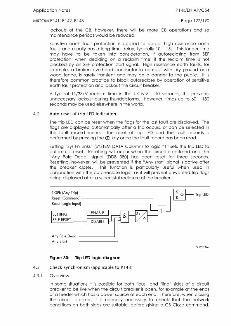
Application Notes P14x/EN AP/C54 MiCOM P141, P142, P143 Page 127/190
lockouts of the CB, however, there will be more CB operations and so maintenance periods would be reduced.
Sensitive earth fault protection is applied to detect high resistance earth faults and usually has a long time delay, typically 10 – 15s. This longer time may have to be taken into consideration, if autoreclosing from SEF protection, when deciding on a reclaim time, if the reclaim time is not blocked by an SEF protection start signal. High resistance earth faults, for example, a broken overhead conductor in contact with dry ground or a wood fence, is rarely transient and may be a danger to the public. It is therefore common practice to block autoreclose by operation of sensitive earth fault protection and lockout the circuit breaker.
A typical 11/33kV reclaim time in the UK is 5 – 10 seconds, this prevents unnecessary lockout during thunderstorms. However, times up to 60 – 180 seconds may be used elsewhere in the world.
4.2 Auto reset of trip LED indication The trip LED can be reset when the flags for the last fault are displayed. The flags are displayed automatically after a trip occurs, or can be selected in the fault record menu. The reset of trip LED and the fault records is performed by pressing the key once the fault record has been read.
Setting “Sys Fn Links” (SYSTEM DATA Column) to logic “1” sets the trip LED to automatic reset. Resetting will occur when the circuit is reclosed and the “Any Pole Dead” signal (DDB 380) has been reset for three seconds. Resetting, however, will be prevented if the “Any start” signal is active after the breaker closes. This function is particularly useful when used in conjunction with the auto-reclose logic, as it will prevent unwanted trip flags being displayed after a successful reclosure of the breaker.
Figure 30: Trip LED logic diagram
4.3 Check synchronism (applicable to P143) 4.3.1 Overview
In some situations it is possible for both “bus” and “line” sides of a circuit breaker to be live when the circuit breaker is open, for example at the ends of a feeder which has a power source at each end. Therefore, when closing the circuit breaker, it is normally necessary to check that the network conditions on both sides are suitable, before giving a CB Close command.
P14x/EN AP/C54 Application Notes Page 128/190 MiCOM P141, P142, P143
This applies to both manual circuit breaker closing and auto-reclosure. If a circuit breaker is closed when the line and bus voltages are both live, with a large phase angle, frequency or magnitude difference between them, the system could be subjected to an unacceptable shock, resulting in loss of stability, and possible damage to connected machines.
System checks involve monitoring the voltages on both sides of a circuit breaker, and, if both sides are live, performing a synchronism check to determine whether the phase angle, frequency and voltage magnitude differences between the voltage vectors, are within permitted limits.
The pre-closing system conditions for a given circuit breaker depend on the system configuration and, for auto-reclosing, on the selected auto-reclose program. For example, on a feeder with delayed auto-reclosing, the circuit breakers at the two line ends are normally arranged to close at different times. The first line end to close usually has a live bus and a dead line immediately before reclosing, and charges the line (dead line charge) when the circuit breaker closes. The second line end circuit breaker sees live bus and live line after the first circuit breaker has reclosed. If there is a parallel connection between the ends of the tripped feeder, they are unlikely to go out of synchronism, i.e. the frequencies will be the same, but the increased impedance could cause the phase angle between the two voltages to increase. Therefore the second circuit breaker to close might need a synchronism check, to ensure that the phase angle has not increased to a level which would cause unacceptable shock to the system when the circuit breaker closes.
If there are no parallel interconnections between the ends of the tripped feeder, the two systems could lose synchronism, and the frequency at one end could “slip” relative to the other end. In this situation, the second line end would require a synchronism check comprising both phase angle and slip frequency checks.
If the second line end busbar has no power source other than the feeder which has tripped, the circuit breaker will see a live line and dead bus assuming the first circuit breaker has reclosed. When the second line end circuit breaker closes the bus will charge from the live line (dead bus charge).
4.3.2 VT selection
The P143 has a three phase “Main VT” input and a single phase “Check Sync VT” input. Depending on the primary system arrangement, the main three phase VT for the relay may be located on either the busbar side or the line side of the circuit breaker, with the check sync VT being located on the other side. Hence, the relay has to be programmed with the location of the main VT. This is done via the “Main VT Location” setting in the CT & VT RATIOS menu.
The Check Sync VT may be connected to either a phase to phase or phase to neutral voltage, and for correct synchronism check operation, the relay has to be programmed with the required connection. The “C/S Input” setting in the CT & VT RATIOS menu should be set to A-N, B-N, C-N, A-B, B-C or C-A as appropriate.
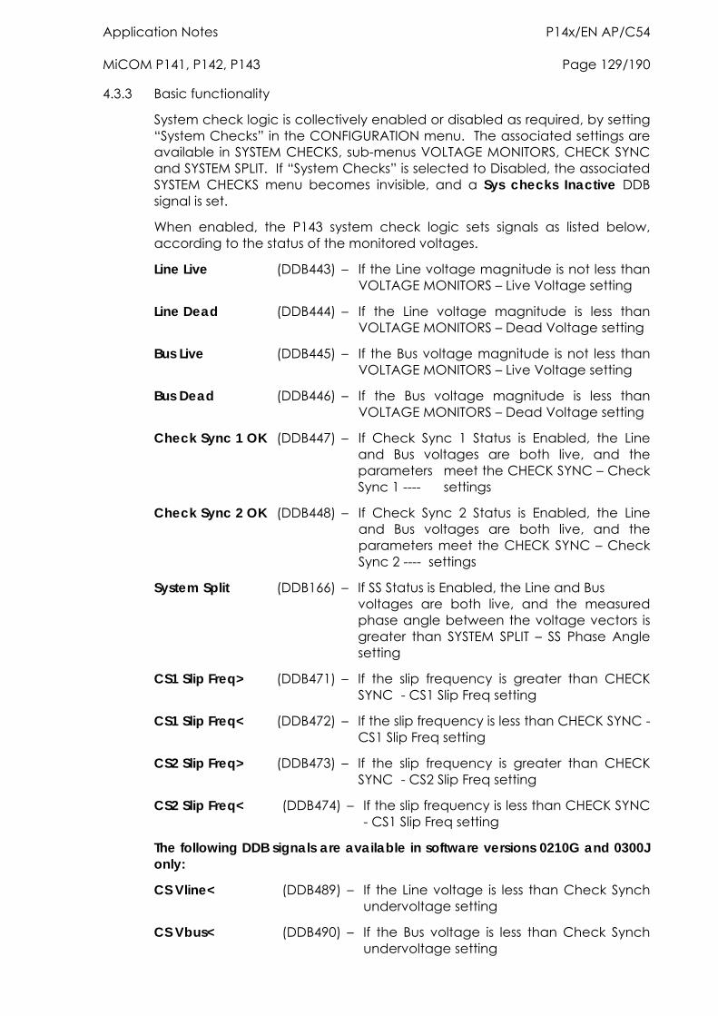
Application Notes P14x/EN AP/C54 MiCOM P141, P142, P143 Page 129/190
4.3.3 Basic functionality
System check logic is collectively enabled or disabled as required, by setting “System Checks” in the CONFIGURATION menu. The associated settings are available in SYSTEM CHECKS, sub-menus VOLTAGE MONITORS, CHECK SYNC and SYSTEM SPLIT. If “System Checks” is selected to Disabled, the associated SYSTEM CHECKS menu becomes invisible, and a Sys checks Inactive DDB signal is set.
When enabled, the P143 system check logic sets signals as listed below, according to the status of the monitored voltages.
Line Live (DDB443) – If the Line voltage magnitude is not less than VOLTAGE MONITORS – Live Voltage setting
Line Dead (DDB444) – If the Line voltage magnitude is less than VOLTAGE MONITORS – Dead Voltage setting
Bus Live (DDB445) – If the Bus voltage magnitude is not less than VOLTAGE MONITORS – Live Voltage setting
Bus Dead (DDB446) – If the Bus voltage magnitude is less than VOLTAGE MONITORS – Dead Voltage setting
Check Sync 1 OK (DDB447) – If Check Sync 1 Status is Enabled, the Line and Bus voltages are both live, and the parameters meet the CHECK SYNC – Check Sync 1 ---- settings
Check Sync 2 OK (DDB448) – If Check Sync 2 Status is Enabled, the Line and Bus voltages are both live, and the parameters meet the CHECK SYNC – Check Sync 2 ---- settings
System Split (DDB166) – If SS Status is Enabled, the Line and Bus voltages are both live, and the measured phase angle between the voltage vectors is greater than SYSTEM SPLIT – SS Phase Angle setting
CS1 Slip Freq> (DDB471) – If the slip frequency is greater than CHECK SYNC - CS1 Slip Freq setting
CS1 Slip Freq< (DDB472) – If the slip frequency is less than CHECK SYNC - CS1 Slip Freq setting
CS2 Slip Freq> (DDB473) – If the slip frequency is greater than CHECK SYNC - CS2 Slip Freq setting
CS2 Slip Freq< (DDB474) – If the slip frequency is less than CHECK SYNC - CS1 Slip Freq setting
The following DDB signals are available in software versions 0210G and 0300J only:
CS Vline< (DDB489) – If the Line voltage is less than Check Synch undervoltage setting
CS Vbus< (DDB490) – If the Bus voltage is less than Check Synch undervoltage setting
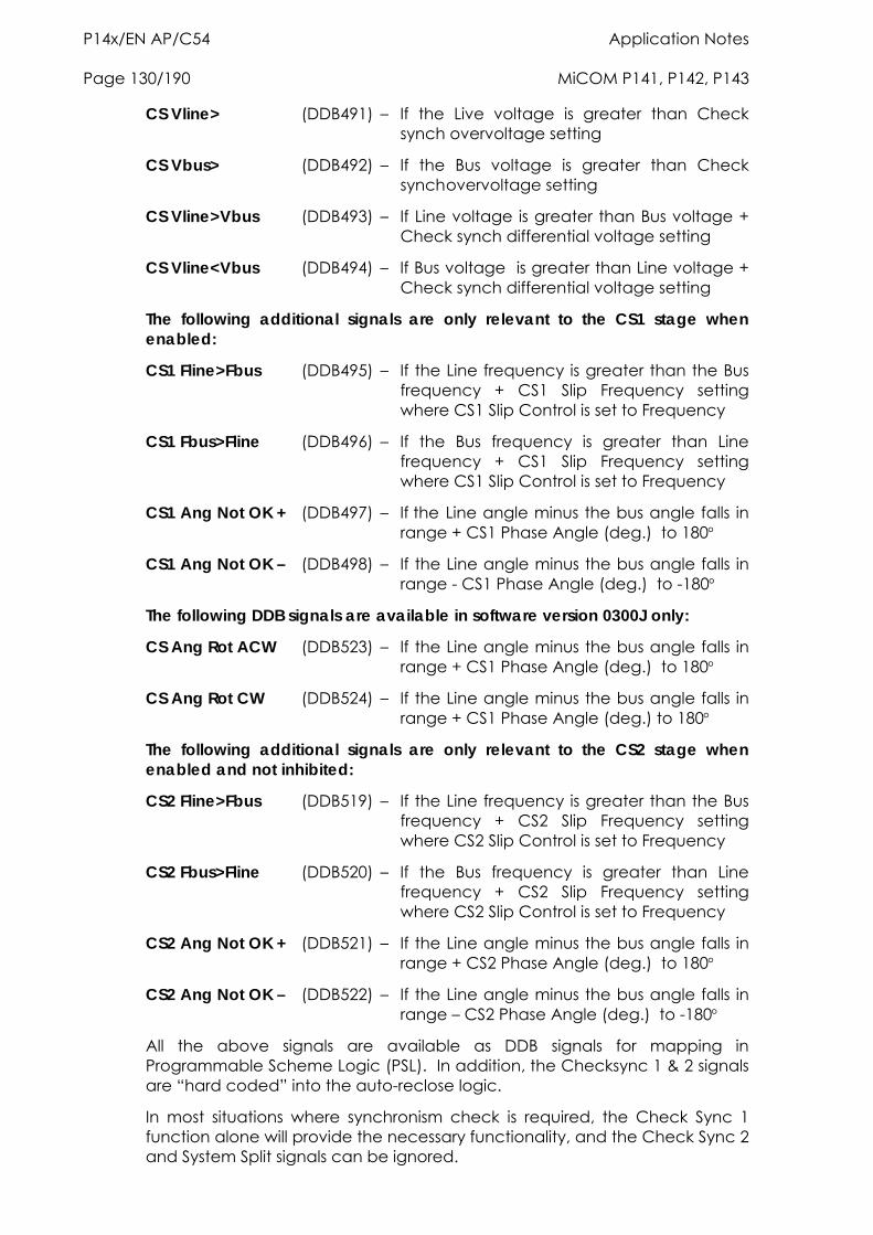
P14x/EN AP/C54 Application Notes Page 130/190 MiCOM P141, P142, P143
CS Vline> (DDB491) – If the Live voltage is greater than Check synch overvoltage setting
CS Vbus> (DDB492) – If the Bus voltage is greater than Check synch overvoltage setting
CS Vline>Vbus (DDB493) – If Line voltage is greater than Bus voltage + Check synch differential voltage setting
CS Vline<Vbus (DDB494) – If Bus voltage is greater than Line voltage + Check synch differential voltage setting
The following additional signals are only relevant to the CS1 stage when enabled:
CS1 Fline>Fbus (DDB495) – If the Line frequency is greater than the Bus frequency + CS1 Slip Frequency setting where CS1 Slip Control is set to Frequency
CS1 Fbus>Fline (DDB496) – If the Bus frequency is greater than Line frequency + CS1 Slip Frequency setting where CS1 Slip Control is set to Frequency
CS1 Ang Not OK + (DDB497) – If the Line angle minus the bus angle falls in range + CS1 Phase Angle (deg.) to 180
CS1 Ang Not OK – (DDB498) – If the Line angle minus the bus angle falls in range - CS1 Phase Angle (deg.) to -180
The following DDB signals are available in software version 0300J only:
CS Ang Rot ACW (DDB523) – If the Line angle minus the bus angle falls in range + CS1 Phase Angle (deg.) to 180
CS Ang Rot CW (DDB524) – If the Line angle minus the bus angle falls in range + CS1 Phase Angle (deg.) to 180
The following additional signals are only relevant to the CS2 stage when enabled and not inhibited:
CS2 Fline>Fbus (DDB519) – If the Line frequency is greater than the Bus frequency + CS2 Slip Frequency setting where CS2 Slip Control is set to Frequency
CS2 Fbus>Fline (DDB520) – If the Bus frequency is greater than Line frequency + CS2 Slip Frequency setting where CS2 Slip Control is set to Frequency
CS2 Ang Not OK + (DDB521) – If the Line angle minus the bus angle falls in range + CS2 Phase Angle (deg.) to 180
CS2 Ang Not OK – (DDB522) – If the Line angle minus the bus angle falls in range – CS2 Phase Angle (deg.) to -180
All the above signals are available as DDB signals for mapping in Programmable Scheme Logic (PSL). In addition, the Checksync 1 & 2 signals are “hard coded” into the auto-reclose logic.
In most situations where synchronism check is required, the Check Sync 1 function alone will provide the necessary functionality, and the Check Sync 2 and System Split signals can be ignored.
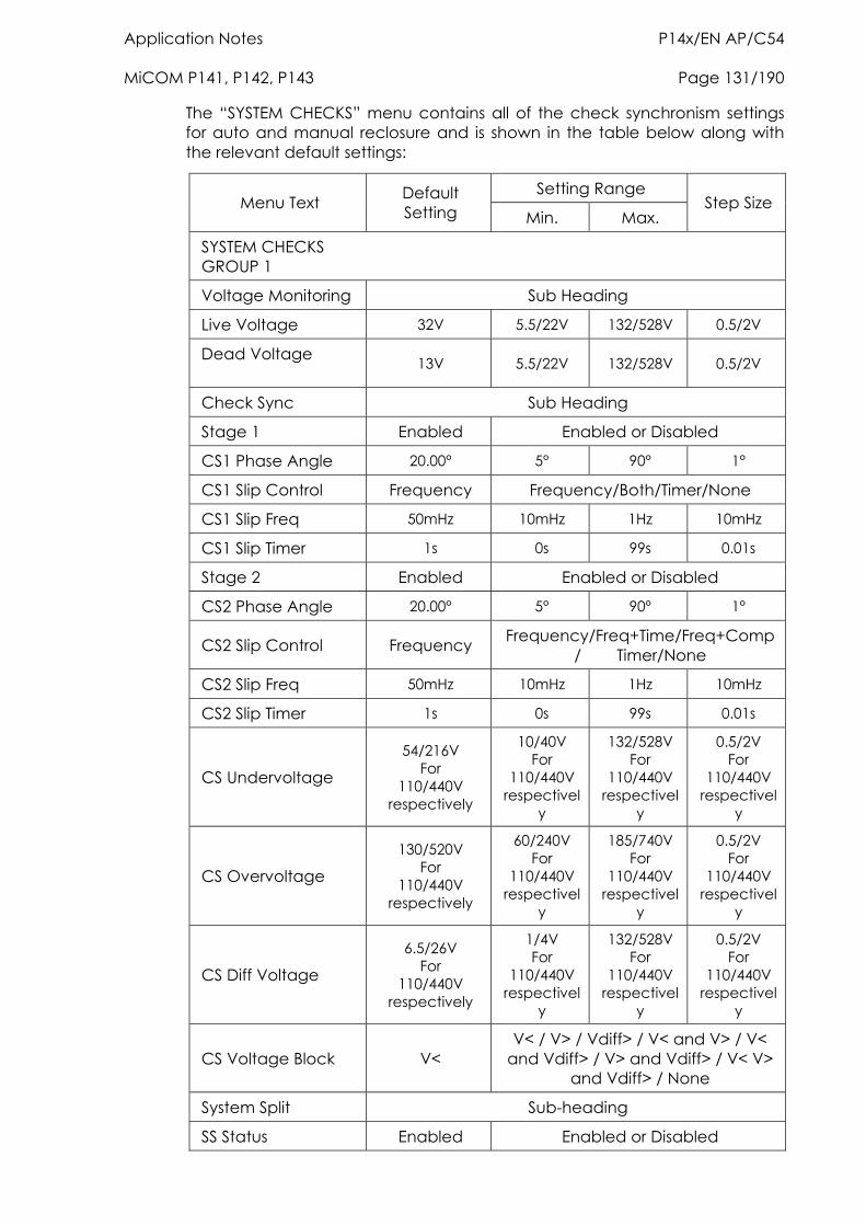
Application Notes P14x/EN AP/C54 MiCOM P141, P142, P143 Page 131/190
The “SYSTEM CHECKS” menu contains all of the check synchronism settings for auto and manual reclosure and is shown in the table below along with the relevant default settings:
Setting Range Menu Text Default
Setting Min. Max. Step Size
SYSTEM CHECKS GROUP 1
Voltage Monitoring Sub Heading
Live Voltage 32V 5.5/22V 132/528V 0.5/2V
Dead Voltage 13V 5.5/22V 132/528V 0.5/2V
Check Sync Sub Heading
Stage 1 Enabled Enabled or Disabled
CS1 Phase Angle 20.00° 5° 90° 1°
CS1 Slip Control Frequency Frequency/Both/Timer/None
CS1 Slip Freq 50mHz 10mHz 1Hz 10mHz
CS1 Slip Timer 1s 0s 99s 0.01s
Stage 2 Enabled Enabled or Disabled
CS2 Phase Angle 20.00° 5° 90° 1°
CS2 Slip Control Frequency Frequency/Freq+Time/Freq+Comp/ Timer/None
CS2 Slip Freq 50mHz 10mHz 1Hz 10mHz
CS2 Slip Timer 1s 0s 99s 0.01s
CS Undervoltage
54/216V For
110/440V respectively
10/40V For
110/440V respectivel
y
132/528V For
110/440V respectivel
y
0.5/2V For
110/440V respectivel
y
CS Overvoltage
130/520V For
110/440V respectively
60/240V For
110/440V respectivel
y
185/740V For
110/440V respectivel
y
0.5/2V For
110/440V respectivel
y
CS Diff Voltage
6.5/26V For
110/440V respectively
1/4V For
110/440V respectivel
y
132/528V For
110/440V respectivel
y
0.5/2V For
110/440V respectivel
y
CS Voltage Block V< V< / V> / Vdiff> / V< and V> / V<
and Vdiff> / V> and Vdiff> / V< V> and Vdiff> / None
System Split Sub-heading
SS Status Enabled Enabled or Disabled
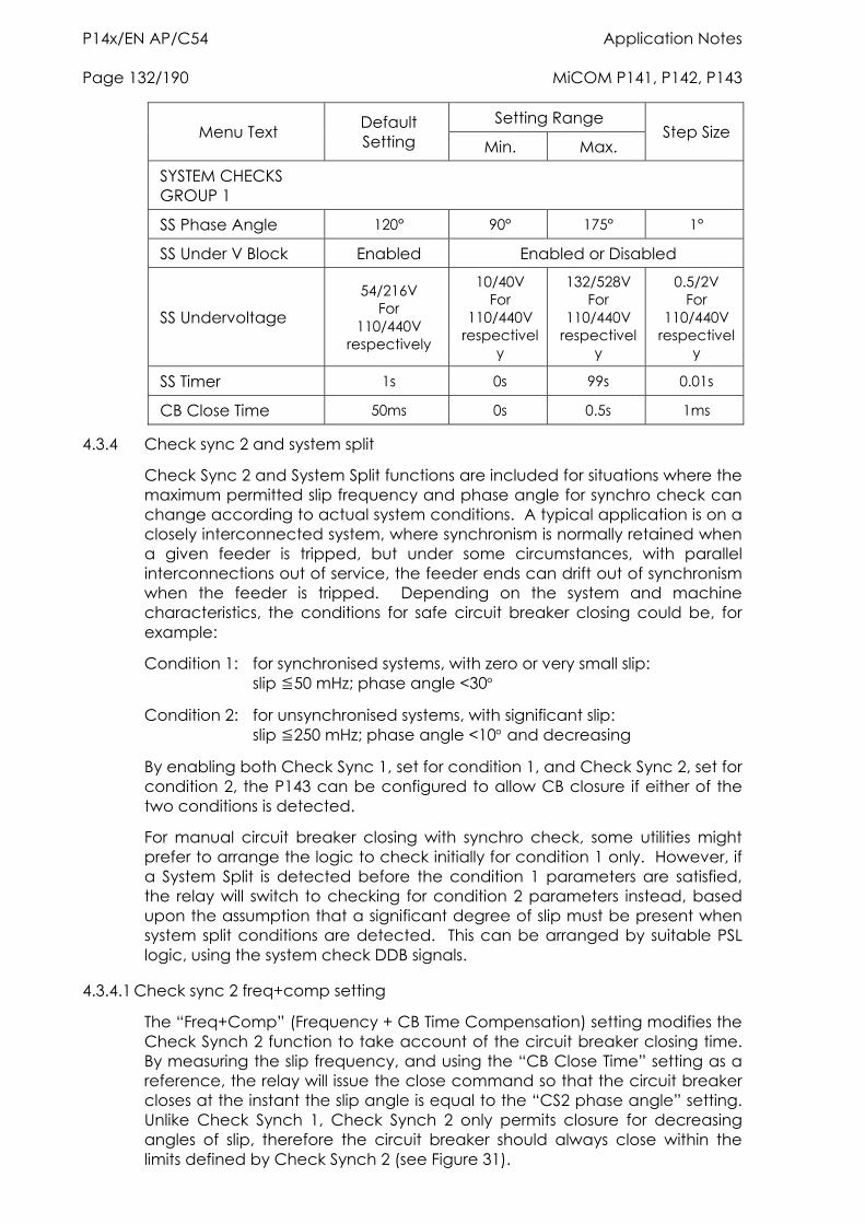
P14x/EN AP/C54 Application Notes Page 132/190 MiCOM P141, P142, P143
Setting Range Menu Text Default
Setting Min. Max. Step Size
SYSTEM CHECKS GROUP 1
SS Phase Angle 120° 90° 175° 1°
SS Under V Block Enabled Enabled or Disabled
SS Undervoltage
54/216V For
110/440V respectively
10/40V For
110/440V respectivel
y
132/528V For
110/440V respectivel
y
0.5/2V For
110/440V respectivel
y
SS Timer 1s 0s 99s 0.01s
CB Close Time 50ms 0s 0.5s 1ms
4.3.4 Check sync 2 and system split
Check Sync 2 and System Split functions are included for situations where the maximum permitted slip frequency and phase angle for synchro check can change according to actual system conditions. A typical application is on a closely interconnected system, where synchronism is normally retained when a given feeder is tripped, but under some circumstances, with parallel interconnections out of service, the feeder ends can drift out of synchronism when the feeder is tripped. Depending on the system and machine characteristics, the conditions for safe circuit breaker closing could be, for example:
Condition 1: for synchronised systems, with zero or very small slip: slip 50 mHz; phase angle <30
Condition 2: for unsynchronised systems, with significant slip: slip 250 mHz; phase angle <10 and decreasing
By enabling both Check Sync 1, set for condition 1, and Check Sync 2, set for condition 2, the P143 can be configured to allow CB closure if either of the two conditions is detected.
For manual circuit breaker closing with synchro check, some utilities might prefer to arrange the logic to check initially for condition 1 only. However, if a System Split is detected before the condition 1 parameters are satisfied, the relay will switch to checking for condition 2 parameters instead, based upon the assumption that a significant degree of slip must be present when system split conditions are detected. This can be arranged by suitable PSL logic, using the system check DDB signals.
4.3.4.1 Check sync 2 freq+comp setting
The “Freq+Comp” (Frequency + CB Time Compensation) setting modifies the Check Synch 2 function to take account of the circuit breaker closing time. By measuring the slip frequency, and using the “CB Close Time” setting as a reference, the relay will issue the close command so that the circuit breaker closes at the instant the slip angle is equal to the “CS2 phase angle” setting. Unlike Check Synch 1, Check Synch 2 only permits closure for decreasing angles of slip, therefore the circuit breaker should always close within the limits defined by Check Synch 2 (see Figure 31).
Application Notes P14x/EN AP/C54 MiCOM P141, P142, P143 Page 133/190
4.3.5 Synchronism check
Check Sync 1 and Check Sync 2 are two synchro check logic modules with similar functionality, but independent settings.
For either module to function:
the System Checks setting must be Enabled AND the individual Check Sync 1(2) Status setting must be Enabled AND the module must be individually “enabled”, by activation of DDB signal Check Sync 1(2) Enabled, mapped in PSL.
When enabled, each logic module sets its output signal when:
line volts and bus volts are both live (Line Live and Bus Live signals both set) AND measured phase angle is < Check Sync 1(2) Phase Angle setting AND (for Check Sync 2 only), the phase angle magnitude is decreasing (Check Sync 1 can operate with increasing or decreasing phase angle provided other conditions are satisfied) AND if Check Sync 1(2) Slip Control is set to Frequency or Frequency + Timer, the measured slip frequency is < Check Sync 1(2) Slip Freq setting AND if Check Sync Voltage Blocking is set to OV, UV + OV, OV + DiffV or UV + OV + DiffV, both line volts and bus volts magnitudes are < Check Sync Overvoltage setting AND if Check Sync Voltage Blocking is set to UV, UV + OV, UV + DiffV or UV + OV + DiffV, both line volts and bus volts magnitudes are > Check Sync Undervoltage setting AND if Check Sync Voltage Blocking is set to DiffV, UV + DiffV, OV + DiffV or UV + OV + DiffV, the voltage magnitude difference between line volts and bus volts is < Check Sync Diff Voltage setting AND if Check Sync 1(2) Slip Control is set to Timer or Frequency + Timer, the above conditions have been true for a time > or = Check Sync 1(2) Slip Timer setting
Note: Live Line / Dead Bus and Dead Bus / Line functionality is provided as part of the default PSL (see Figure 33).
4.3.6 Slip control by timer
If Slip Control by Timer or Frequency + Timer is selected, the combination of Phase Angle and Timer settings determines an effective maximum slip frequency, calculated as:
2 x A Hz. for Check Sync 1, or T x 360
A Hz. for Check Sync 2 T x 360
P14x/EN AP/C54 Application Notes Page 134/190 MiCOM P141, P142, P143
where
A = Phase Angle setting () T = Slip Timer setting (seconds)
For example, with Check Sync 1 Phase Angle setting 30 and Timer setting 3.3 sec, the “slipping” vector has to remain within 30 of the reference vector for at least 3.3 seconds. Therefore a synchro check output will not be given if the slip is greater than 2 x 30 in 3.3 seconds. Using the formula: 2 x 30 (3.3 x 360) = 0.0505 Hz (50.5 mHz).
For Check Sync 2, with Phase Angle setting 10 and Timer setting 0.1 sec, the slipping vector has to remain within 10 of the reference vector, with the angle decreasing, for 0.1 sec. When the angle passes through zero and starts to increase, the synchro check output is blocked. Therefore an output will not be given if slip is greater than 10 in 0.1 second. Using the formula: 10 (0.1 x 360) = 0.278 Hz (278 mHz).
Slip control by Timer is not practical for “large slip / small phase angle” applications, because the timer settings required are very small, sometimes < 0.1s. For these situations, slip control by frequency is recommended.
If Slip Control by Frequency + Timer is selected, for an output to be given, the slip frequency must be less than BOTH the set Slip Freq value and the value determined by the Phase Angle and Timer settings.
4.3.7 System split
For the System Split module to function:
the System Checks setting must be Enabled AND the SS Status setting must be Enabled AND the module must be individually “enabled”, by activation of DDB signal System Split Enabled, mapped in PSL
When enabled, the System Split module sets its output signal when:
line volts and bus volts are both live (Line Live and Bus Live signals both set) AND measured phase angle is > SS Phase Angle setting AND if SS Volt Blocking is set to Undervoltage, both line volts and bus volts magnitudes are > SS Undervoltage setting
The System Split output remains set for as long as the above conditions are true, or for a minimum period equal to the SS Timer setting, whichever is longer.
The “Check Synch” and “System Synch” functionality is illustrated in the Figure 31.
The overall system checks functionality is shown in Figure 32.
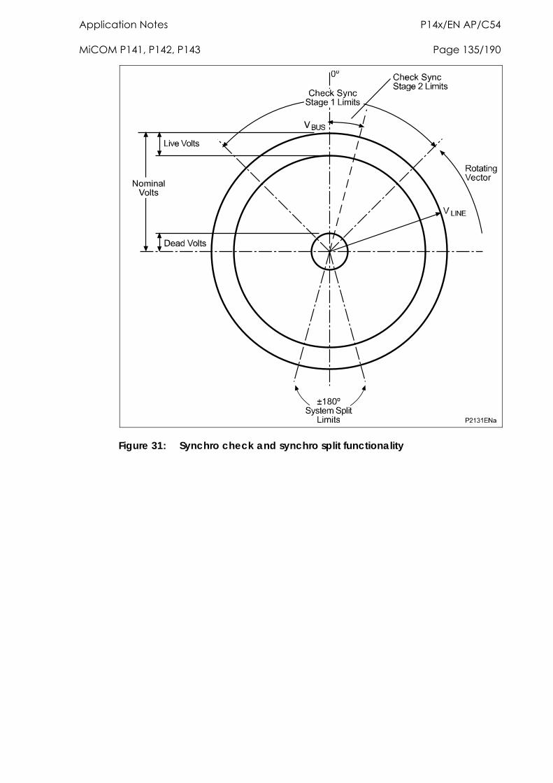
Application Notes P14x/EN AP/C54 MiCOM P141, P142, P143 Page 135/190
Figure 31: Synchro check and synchro split functionality
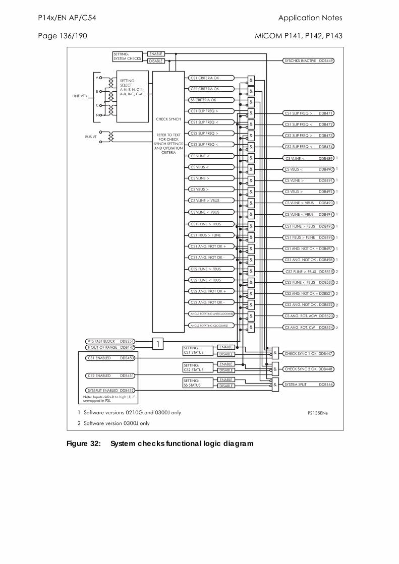
P14x/EN AP/C54 Application Notes Page 136/190 MiCOM P141, P142, P143
8���&,3�
(���(#0 ,#0��/B
(���(#0 ,#0��/B
���(#0 ,#0��/B
(����$08�)#,?�7
(����$08�)#,?�1
(����$08�)#,?�7
(����$08�)#,?�1
;
;
;
;
;
;
;
(C,(B��D3(C
,3��$,
�0���$,
�, 03���D� ,E�(C,(B�
�, 03���,$,( �:3F��:3F�(:3F�:�F��:(F�(:�
�
�
(
3
$03,�5 G
�D�(CB��03�( 05,��������6
�H��5
(����$08�)#,?�7������������
(����$08�)#,?�1������������
(����$08�)#,?�7������������
(����$08�)#,?�1������������
5 ��)�� ��$/(B���������&�
(C,(B��D3(���/B��������
(C,(B��D3(���/B�������4
�D� ,E��8$0 ����������������22
;
;
;
,3��$,
�0���$,
�, 03��(���� � H�
,3��$,
�0���$,
,3��$,
�0���$,
�, 03��(���� � H�
�, 03������ � H�
(���,3��$,��������������&�
(���,3��$,��������������&�
�D��8$0 �,3��$,�������&�
3�����0�!>� ����>������'�I'�"�%���>�*!!������8�$
#,),#� /� ,J )/#�(C,(B
�D3(C��, 03���3��/8,#� 0/3
(#0 ,#0�
)�/H �/)�#�3�,��������� �
(��5$03,�1
(��5�H��1
(��5$03,�7
(��5�H��7
;
;
;
;
(��5$03,�1�����������������46
(��5�H��1�������������������6�
(��5$03,�7������������������6�
(��5�H��7�������������������6�
(��5$03,�7�5�H�; (��5$03,�7�5�H����������6�
(��5$03,�1�5�H� ; (��5$03,�1�5�H����������6�
(���)$03,�7�)�H�
(���)�H��7�)$03,
(����3�.�3/ �/B�K
(����3�.�3/ �/B�:
;
;
;
;
(���)$03,�7�)�H���������6&
(���)�H��7�)$03,��������62
(����3�.�3/ �/B�K�����6�
(����3�.�3/ �/B�:�����64
(���)$03,�7�)�H�
(���)$03,�1�)�H�
(����3�.�3/ �/B�K
(����3�.�3/ �/B�:
;
;
;
;
(���)$03,�7�)�H�������&�6
(���)$03,�1�)�H��������&��
(����3�.�3/ �/B�K����&��
(����3�.�3/ �/B�:����&��
; (���3�.�#/ .��(L�����&��
; (���3�.�#/ .�(L�������&��
�3�$,�#/ � 03���3 0($/(BL0�,
�3�$,�#/ � 03��($/(BL0�,
������������ ��� ��������������������
������������ ��������������
�
�
�
�
�
�
�
�
�
�
�
�
�
�
�
�
Figure 32: System checks functional logic diagram
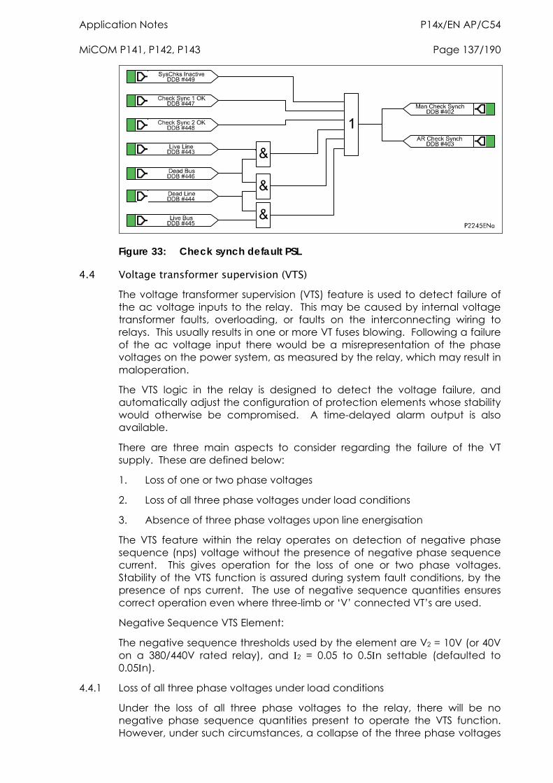
Application Notes P14x/EN AP/C54 MiCOM P141, P142, P143 Page 137/190
Figure 33: Check synch default PSL
4.4 Voltage transformer supervision (VTS) The voltage transformer supervision (VTS) feature is used to detect failure of the ac voltage inputs to the relay. This may be caused by internal voltage transformer faults, overloading, or faults on the interconnecting wiring to relays. This usually results in one or more VT fuses blowing. Following a failure of the ac voltage input there would be a misrepresentation of the phase voltages on the power system, as measured by the relay, which may result in maloperation.
The VTS logic in the relay is designed to detect the voltage failure, and automatically adjust the configuration of protection elements whose stability would otherwise be compromised. A time-delayed alarm output is also available.
There are three main aspects to consider regarding the failure of the VT supply. These are defined below:
1. Loss of one or two phase voltages
2. Loss of all three phase voltages under load conditions
3. Absence of three phase voltages upon line energisation
The VTS feature within the relay operates on detection of negative phase sequence (nps) voltage without the presence of negative phase sequence current. This gives operation for the loss of one or two phase voltages. Stability of the VTS function is assured during system fault conditions, by the presence of nps current. The use of negative sequence quantities ensures correct operation even where three-limb or ‘V’ connected VT’s are used.
Negative Sequence VTS Element:
The negative sequence thresholds used by the element are V2 = 10V (or 40V on a 380/440V rated relay), and 2 = 0.05 to 0.5n settable (defaulted to 0.05n).
4.4.1 Loss of all three phase voltages under load conditions
Under the loss of all three phase voltages to the relay, there will be no negative phase sequence quantities present to operate the VTS function. However, under such circumstances, a collapse of the three phase voltages
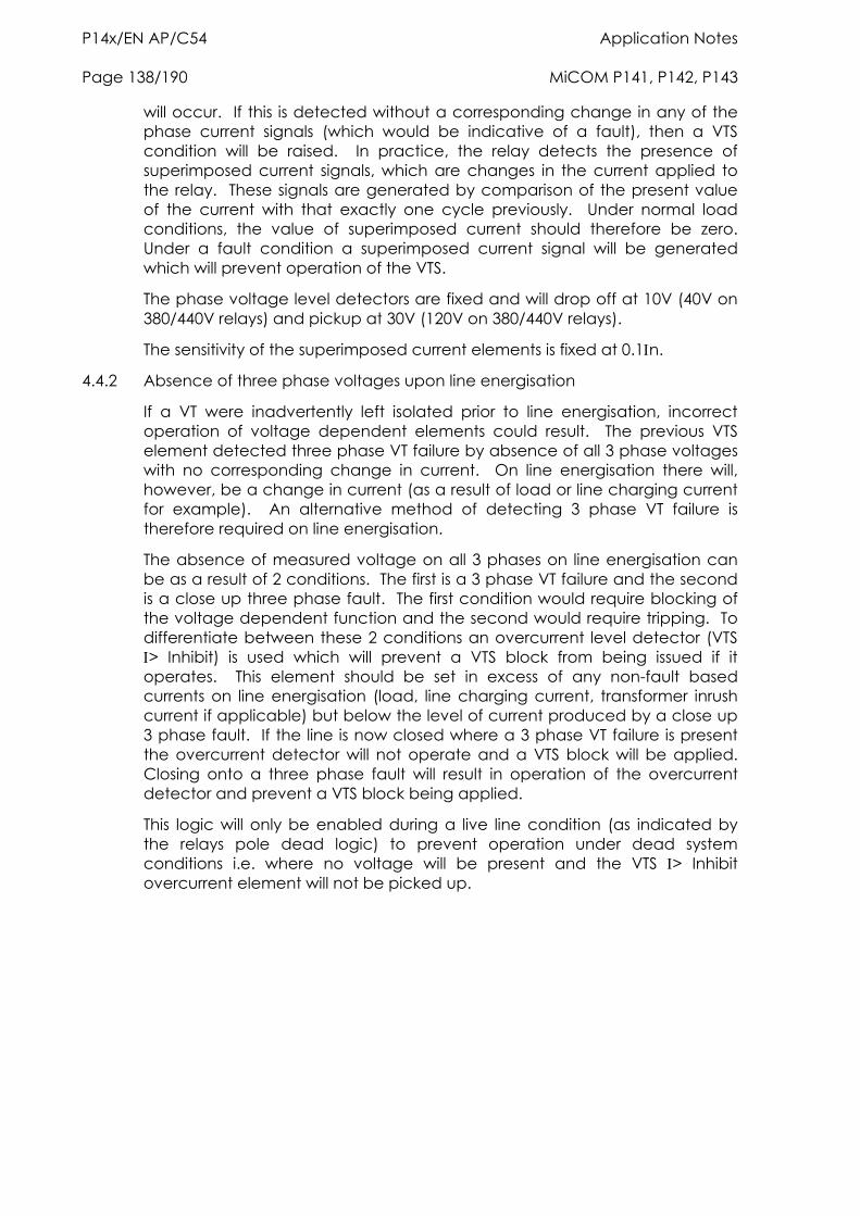
P14x/EN AP/C54 Application Notes Page 138/190 MiCOM P141, P142, P143
will occur. If this is detected without a corresponding change in any of the phase current signals (which would be indicative of a fault), then a VTS condition will be raised. In practice, the relay detects the presence of superimposed current signals, which are changes in the current applied to the relay. These signals are generated by comparison of the present value of the current with that exactly one cycle previously. Under normal load conditions, the value of superimposed current should therefore be zero. Under a fault condition a superimposed current signal will be generated which will prevent operation of the VTS.
The phase voltage level detectors are fixed and will drop off at 10V (40V on 380/440V relays) and pickup at 30V (120V on 380/440V relays).
The sensitivity of the superimposed current elements is fixed at 0.1n.
4.4.2 Absence of three phase voltages upon line energisation
If a VT were inadvertently left isolated prior to line energisation, incorrect operation of voltage dependent elements could result. The previous VTS element detected three phase VT failure by absence of all 3 phase voltages with no corresponding change in current. On line energisation there will, however, be a change in current (as a result of load or line charging current for example). An alternative method of detecting 3 phase VT failure is therefore required on line energisation.
The absence of measured voltage on all 3 phases on line energisation can be as a result of 2 conditions. The first is a 3 phase VT failure and the second is a close up three phase fault. The first condition would require blocking of the voltage dependent function and the second would require tripping. To differentiate between these 2 conditions an overcurrent level detector (VTS > Inhibit) is used which will prevent a VTS block from being issued if it operates. This element should be set in excess of any non-fault based currents on line energisation (load, line charging current, transformer inrush current if applicable) but below the level of current produced by a close up 3 phase fault. If the line is now closed where a 3 phase VT failure is present the overcurrent detector will not operate and a VTS block will be applied. Closing onto a three phase fault will result in operation of the overcurrent detector and prevent a VTS block being applied.
This logic will only be enabled during a live line condition (as indicated by the relays pole dead logic) to prevent operation under dead system conditions i.e. where no voltage will be present and the VTS > Inhibit overcurrent element will not be picked up.
Application Notes P14x/EN AP/C54 MiCOM P141, P142, P143 Page 139/190
Note : The Accelerated Ind input is not used in the Feeder Protection.
Figure 34: VTS Logic
Required to drive the VTS logic are a number of dedicated level detectors as follows:
A>, B>, C> these level detectors shall operate in less than 20ms and their settings should be greater than load current. This setting is specified as VTS current threshold. These level detectors shall pick-up at 100% of setting and drop-off at 95% of setting.
2> this level detector operating on negative sequence current and shall have a user setting. This level detector shall pick-up at 100% of setting and drop-off at 95% of setting.
IA>, B>, C> these are level detectors operating on superimposed phase currents they shall have a fixed setting of 10% of nominal. These level detectors will be subject to a count strategy such that 0.5 cycle of operate decisions must have occured before operation.
VA>, VB>, VC> these are level detectors operating on phase voltages they shall have a fixed setting Pickup level 30V (Vn 100/120V), 120V (Vn 380/440V), Drop Off level 10V (Vn 100/120V), 40V (Vn 380/440V).
V2> this level detector operates on negative sequence voltage, it will have a fixed setting of 10V/40V depending on VT ratio (100/120 or 380/440) with pick-up at 100% of setting and drop-off at 95% of setting.
4.4.2.1 Inputs
Signal Name Description
A>, B>, C> Phase current levels (Fourier Magnitudes)
2> 2 level (Fourier Magnitude).
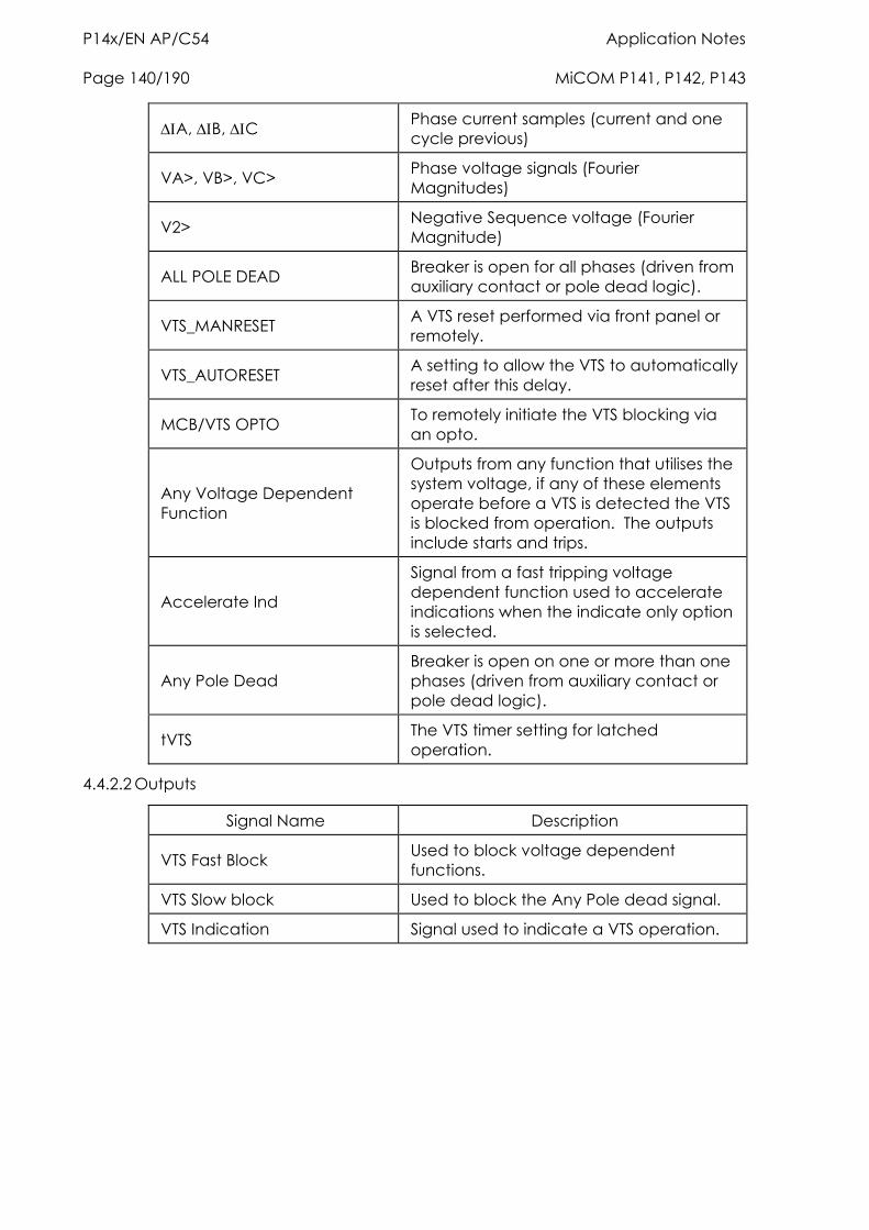
P14x/EN AP/C54 Application Notes Page 140/190 MiCOM P141, P142, P143
A, B, C Phase current samples (current and one cycle previous)
VA>, VB>, VC> Phase voltage signals (Fourier Magnitudes)
V2> Negative Sequence voltage (Fourier Magnitude)
ALL POLE DEAD Breaker is open for all phases (driven from auxiliary contact or pole dead logic).
VTS_MANRESET A VTS reset performed via front panel or remotely.
VTS_AUTORESET A setting to allow the VTS to automatically reset after this delay.
MCB/VTS OPTO To remotely initiate the VTS blocking via an opto.
Any Voltage Dependent Function
Outputs from any function that utilises the system voltage, if any of these elements operate before a VTS is detected the VTS is blocked from operation. The outputs include starts and trips.
Accelerate Ind
Signal from a fast tripping voltage dependent function used to accelerate indications when the indicate only option is selected.
Any Pole Dead Breaker is open on one or more than one phases (driven from auxiliary contact or pole dead logic).
tVTS The VTS timer setting for latched operation.
4.4.2.2 Outputs
Signal Name Description
VTS Fast Block Used to block voltage dependent functions.
VTS Slow block Used to block the Any Pole dead signal.
VTS Indication Signal used to indicate a VTS operation.
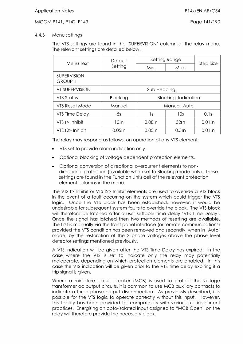
Application Notes P14x/EN AP/C54 MiCOM P141, P142, P143 Page 141/190
4.4.3 Menu settings
The VTS settings are found in the ‘SUPERVISION’ column of the relay menu. The relevant settings are detailed below.
Setting Range Menu Text Default
Setting Min. Max. Step Size
SUPERVISION GROUP 1
VT SUPERVISION Sub Heading
VTS Status Blocking Blocking, Indication
VTS Reset Mode Manual Manual, Auto
VTS Time Delay 5s 1s 10s 0.1s
VTS > Inhibit 10n 0.08n 32n 0.01n
VTS 2> Inhibit 0.05n 0.05n 0.5n 0.01n
The relay may respond as follows, on operation of any VTS element:
VTS set to provide alarm indication only.
Optional blocking of voltage dependent protection elements.
Optional conversion of directional overcurrent elements to non-directional protection (available when set to Blocking mode only). These settings are found in the Function Links cell of the relevant protection element columns in the menu.
The VTS > Inhibit or VTS 2> Inhibit elements are used to override a VTS block in the event of a fault occurring on the system which could trigger the VTS logic. Once the VTS block has been established, however, it would be undesirable for subsequent system faults to override the block. The VTS block will therefore be latched after a user settable time delay ‘VTS Time Delay’. Once the signal has latched then two methods of resetting are available. The first is manually via the front panel interface (or remote communications) provided the VTS condition has been removed and secondly, when in ‘Auto’ mode, by the restoration of the 3 phase voltages above the phase level detector settings mentioned previously.
A VTS indication will be given after the VTS Time Delay has expired. In the case where the VTS is set to indicate only the relay may potentially maloperate, depending on which protection elements are enabled. In this case the VTS indication will be given prior to the VTS time delay expiring if a trip signal is given.
Where a miniature circuit breaker (MCB) is used to protect the voltage transformer ac output circuits, it is common to use MCB auxiliary contacts to indicate a three phase output disconnection. As previously described, it is possible for the VTS logic to operate correctly without this input. However, this facility has been provided for compatibility with various utilities current practices. Energising an opto-isolated input assigned to “MCB Open” on the relay will therefore provide the necessary block.
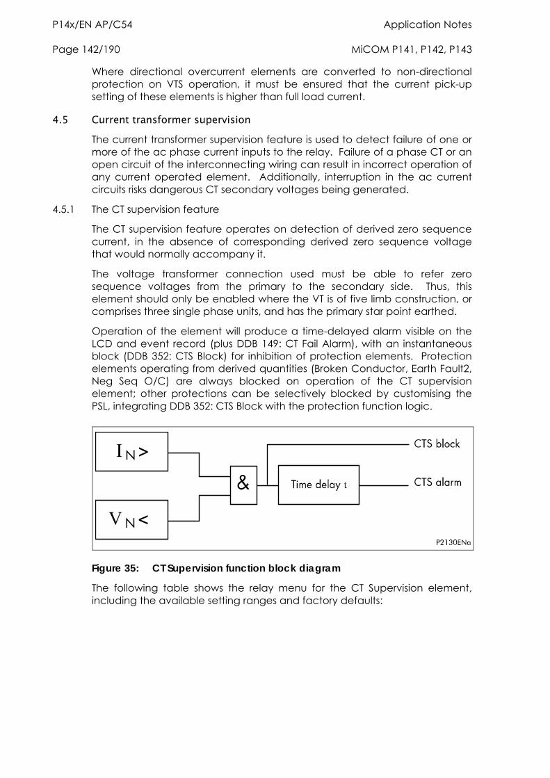
P14x/EN AP/C54 Application Notes Page 142/190 MiCOM P141, P142, P143
Where directional overcurrent elements are converted to non-directional protection on VTS operation, it must be ensured that the current pick-up setting of these elements is higher than full load current.
4.5 Current transformer supervision The current transformer supervision feature is used to detect failure of one or more of the ac phase current inputs to the relay. Failure of a phase CT or an open circuit of the interconnecting wiring can result in incorrect operation of any current operated element. Additionally, interruption in the ac current circuits risks dangerous CT secondary voltages being generated.
4.5.1 The CT supervision feature
The CT supervision feature operates on detection of derived zero sequence current, in the absence of corresponding derived zero sequence voltage that would normally accompany it.
The voltage transformer connection used must be able to refer zero sequence voltages from the primary to the secondary side. Thus, this element should only be enabled where the VT is of five limb construction, or comprises three single phase units, and has the primary star point earthed.
Operation of the element will produce a time-delayed alarm visible on the LCD and event record (plus DDB 149: CT Fail Alarm), with an instantaneous block (DDB 352: CTS Block) for inhibition of protection elements. Protection elements operating from derived quantities (Broken Conductor, Earth Fault2, Neg Seq O/C) are always blocked on operation of the CT supervision element; other protections can be selectively blocked by customising the PSL, integrating DDB 352: CTS Block with the protection function logic.
Figure 35: CT Supervision function block diagram
The following table shows the relay menu for the CT Supervision element, including the available setting ranges and factory defaults:
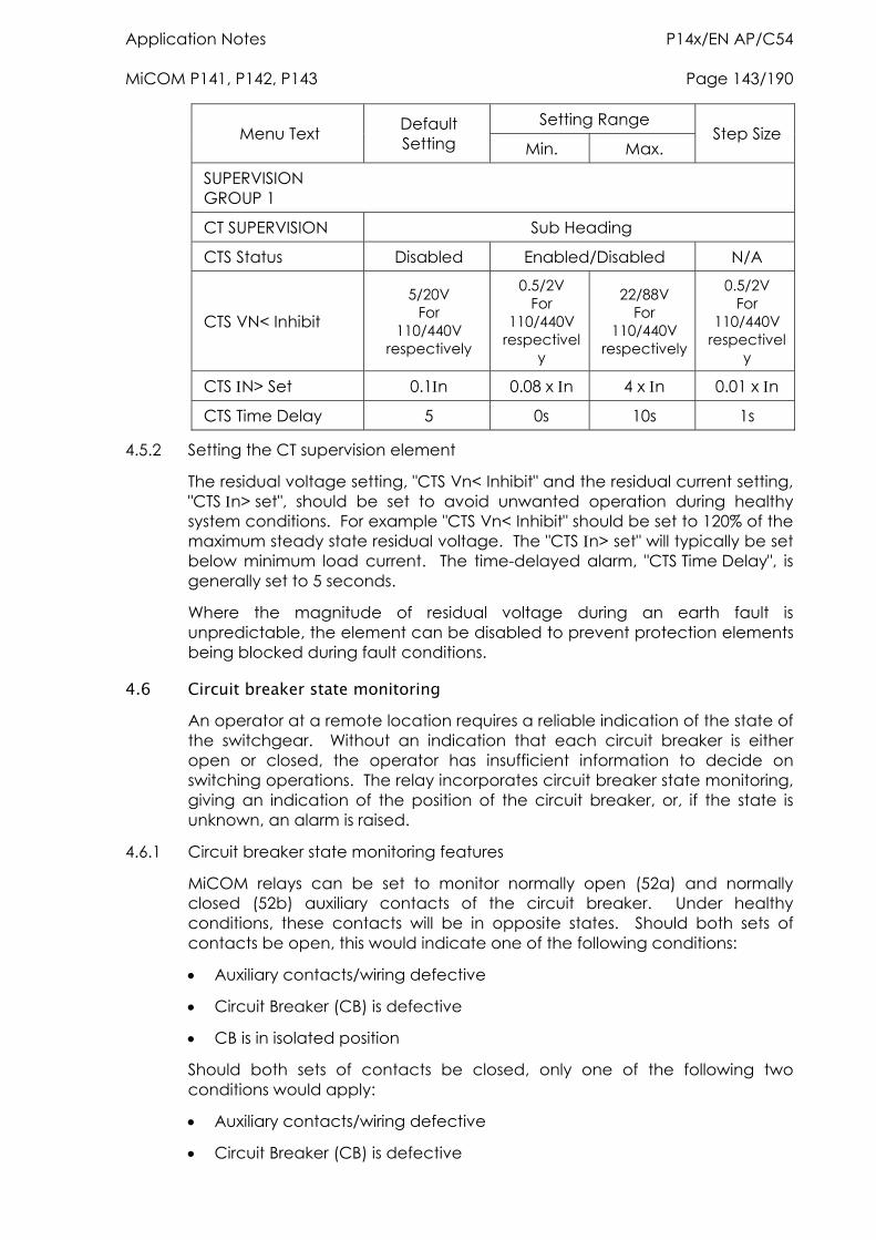
Application Notes P14x/EN AP/C54 MiCOM P141, P142, P143 Page 143/190
Setting Range Menu Text Default
Setting Min. Max. Step Size
SUPERVISION GROUP 1
CT SUPERVISION Sub Heading
CTS Status Disabled Enabled/Disabled N/A
CTS VN< Inhibit
5/20V For
110/440V respectively
0.5/2V For
110/440V respectivel
y
22/88V For
110/440V respectively
0.5/2V For
110/440V respectivel
y
CTS N> Set 0.1n 0.08 x n 4 x n 0.01 x n
CTS Time Delay 5 0s 10s 1s
4.5.2 Setting the CT supervision element
The residual voltage setting, "CTS Vn< Inhibit" and the residual current setting, "CTS n> set", should be set to avoid unwanted operation during healthy system conditions. For example "CTS Vn< Inhibit" should be set to 120% of the maximum steady state residual voltage. The "CTS n> set" will typically be set below minimum load current. The time-delayed alarm, "CTS Time Delay", is generally set to 5 seconds.
Where the magnitude of residual voltage during an earth fault is unpredictable, the element can be disabled to prevent protection elements being blocked during fault conditions.
4.6 Circuit breaker state monitoring An operator at a remote location requires a reliable indication of the state of the switchgear. Without an indication that each circuit breaker is either open or closed, the operator has insufficient information to decide on switching operations. The relay incorporates circuit breaker state monitoring, giving an indication of the position of the circuit breaker, or, if the state is unknown, an alarm is raised.
4.6.1 Circuit breaker state monitoring features
MiCOM relays can be set to monitor normally open (52a) and normally closed (52b) auxiliary contacts of the circuit breaker. Under healthy conditions, these contacts will be in opposite states. Should both sets of contacts be open, this would indicate one of the following conditions:
Auxiliary contacts/wiring defective
Circuit Breaker (CB) is defective
CB is in isolated position
Should both sets of contacts be closed, only one of the following two conditions would apply:
Auxiliary contacts/wiring defective
Circuit Breaker (CB) is defective
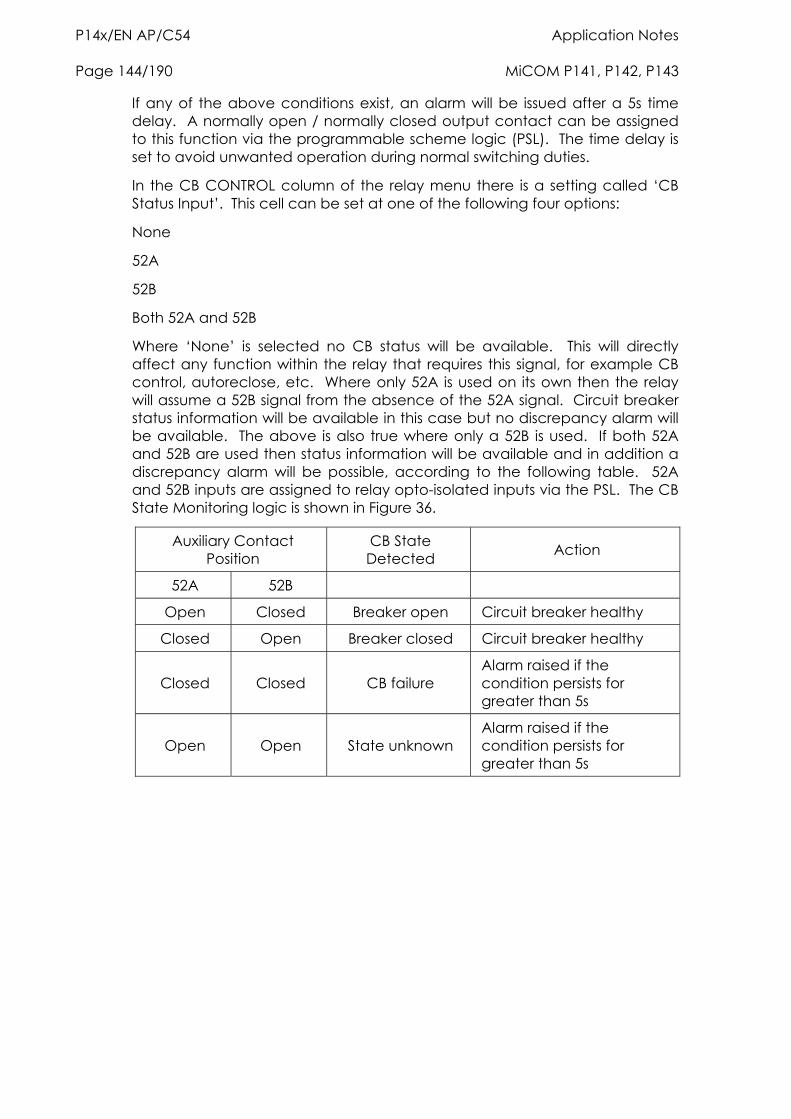
P14x/EN AP/C54 Application Notes Page 144/190 MiCOM P141, P142, P143
If any of the above conditions exist, an alarm will be issued after a 5s time delay. A normally open / normally closed output contact can be assigned to this function via the programmable scheme logic (PSL). The time delay is set to avoid unwanted operation during normal switching duties.
In the CB CONTROL column of the relay menu there is a setting called ‘CB Status Input’. This cell can be set at one of the following four options:
None
52A
52B
Both 52A and 52B
Where ‘None’ is selected no CB status will be available. This will directly affect any function within the relay that requires this signal, for example CB control, autoreclose, etc. Where only 52A is used on its own then the relay will assume a 52B signal from the absence of the 52A signal. Circuit breaker status information will be available in this case but no discrepancy alarm will be available. The above is also true where only a 52B is used. If both 52A and 52B are used then status information will be available and in addition a discrepancy alarm will be possible, according to the following table. 52A and 52B inputs are assigned to relay opto-isolated inputs via the PSL. The CB State Monitoring logic is shown in Figure 36.
Auxiliary Contact Position
CB State Detected Action
52A 52B
Open Closed Breaker open Circuit breaker healthy
Closed Open Breaker closed Circuit breaker healthy
Closed Closed CB failure Alarm raised if the condition persists for greater than 5s
Open Open State unknown Alarm raised if the condition persists for greater than 5s
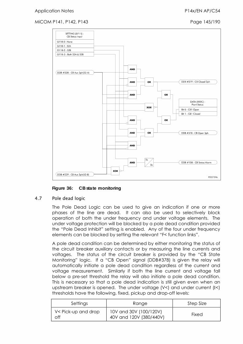
Application Notes P14x/EN AP/C54 MiCOM P141, P142, P143 Page 145/190
Figure 36: CB state monitoring
4.7 Pole dead logic The Pole Dead Logic can be used to give an indication if one or more phases of the line are dead. It can also be used to selectively block operation of both the under frequency and under voltage elements. The under voltage protection will be blocked by a pole dead condition provided the “Pole Dead Inhibit” setting is enabled. Any of the four under frequency elements can be blocked by setting the relevant “F< function links”.
A pole dead condition can be determined by either monitoring the status of the circuit breaker auxiliary contacts or by measuring the line currents and voltages. The status of the circuit breaker is provided by the “CB State Monitoring” logic. If a “CB Open” signal (DDB#378) is given the relay will automatically initiate a pole dead condition regardless of the current and voltage measurement. Similarly if both the line current and voltage fall below a pre-set threshold the relay will also initiate a pole dead condition. This is necessary so that a pole dead indication is still given even when an upstream breaker is opened. The under voltage (V<) and under current (<) thresholds have the following, fixed, pickup and drop-off levels:
Settings Range Step Size
V< Pick-up and drop off
10V and 30V (100/120V) 40V and 120V (380/440V) Fixed
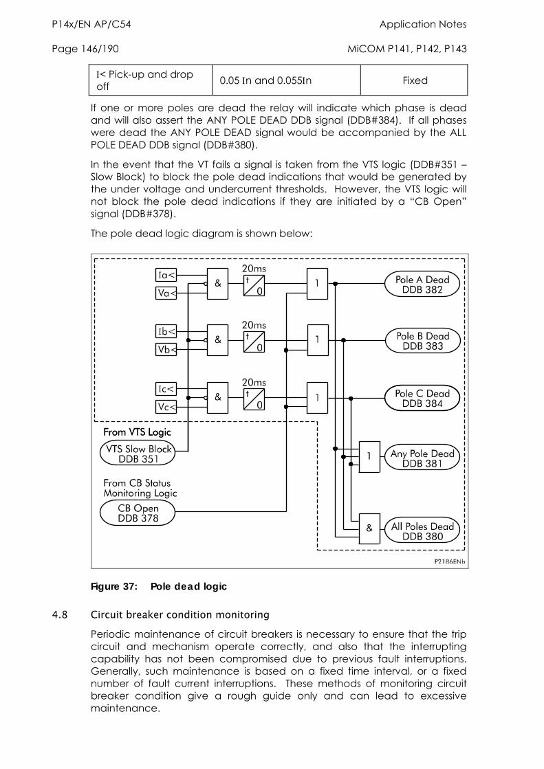
P14x/EN AP/C54 Application Notes Page 146/190 MiCOM P141, P142, P143
< Pick-up and drop off 0.05 n and 0.055n Fixed
If one or more poles are dead the relay will indicate which phase is dead and will also assert the ANY POLE DEAD DDB signal (DDB#384). If all phases were dead the ANY POLE DEAD signal would be accompanied by the ALL POLE DEAD DDB signal (DDB#380).
In the event that the VT fails a signal is taken from the VTS logic (DDB#351 – Slow Block) to block the pole dead indications that would be generated by the under voltage and undercurrent thresholds. However, the VTS logic will not block the pole dead indications if they are initiated by a “CB Open” signal (DDB#378).
The pole dead logic diagram is shown below:
Figure 37: Pole dead logic
4.8 Circuit breaker condition monitoring Periodic maintenance of circuit breakers is necessary to ensure that the trip circuit and mechanism operate correctly, and also that the interrupting capability has not been compromised due to previous fault interruptions. Generally, such maintenance is based on a fixed time interval, or a fixed number of fault current interruptions. These methods of monitoring circuit breaker condition give a rough guide only and can lead to excessive maintenance.
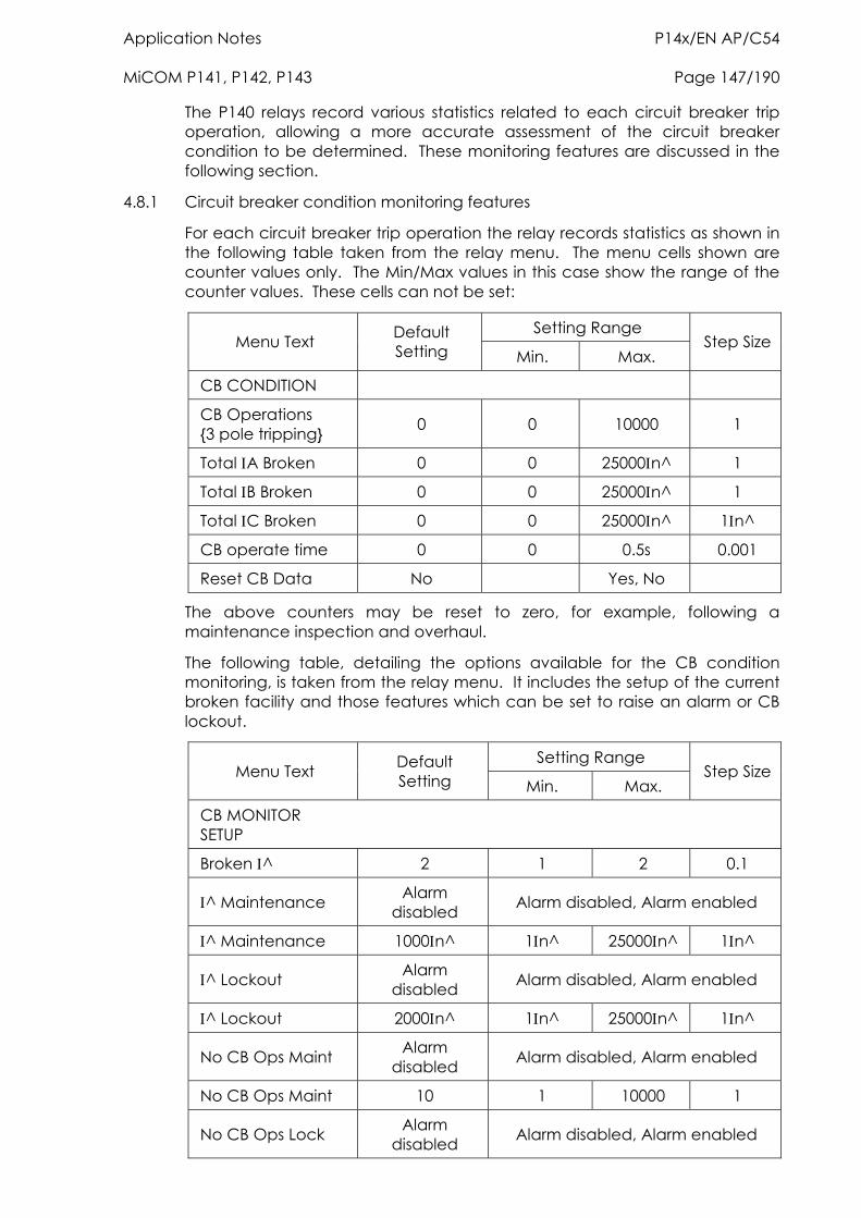
Application Notes P14x/EN AP/C54 MiCOM P141, P142, P143 Page 147/190
The P140 relays record various statistics related to each circuit breaker trip operation, allowing a more accurate assessment of the circuit breaker condition to be determined. These monitoring features are discussed in the following section.
4.8.1 Circuit breaker condition monitoring features
For each circuit breaker trip operation the relay records statistics as shown in the following table taken from the relay menu. The menu cells shown are counter values only. The Min/Max values in this case show the range of the counter values. These cells can not be set:
Setting Range Menu Text Default
Setting Min. Max. Step Size
CB CONDITION
CB Operations {3 pole tripping} 0 0 10000 1
Total A Broken 0 0 25000n^ 1
Total B Broken 0 0 25000n^ 1
Total C Broken 0 0 25000n^ 1n^
CB operate time 0 0 0.5s 0.001
Reset CB Data No Yes, No
The above counters may be reset to zero, for example, following a maintenance inspection and overhaul.
The following table, detailing the options available for the CB condition monitoring, is taken from the relay menu. It includes the setup of the current broken facility and those features which can be set to raise an alarm or CB lockout.
Setting Range Menu Text Default
Setting Min. Max. Step Size
CB MONITOR SETUP
Broken ^ 2 1 2 0.1
^ Maintenance Alarm disabled Alarm disabled, Alarm enabled
^ Maintenance 1000n^ 1n^ 25000n^ 1n^
^ Lockout Alarm disabled Alarm disabled, Alarm enabled
^ Lockout 2000n^ 1n^ 25000n^ 1n^
No CB Ops Maint Alarm disabled Alarm disabled, Alarm enabled
No CB Ops Maint 10 1 10000 1
No CB Ops Lock Alarm disabled Alarm disabled, Alarm enabled
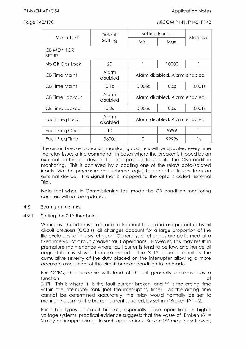
P14x/EN AP/C54 Application Notes Page 148/190 MiCOM P141, P142, P143
Setting Range Menu Text Default
Setting Min. Max. Step Size
CB MONITOR SETUP
No CB Ops Lock 20 1 10000 1
CB Time Maint Alarm disabled Alarm disabled, Alarm enabled
CB Time Maint 0.1s 0.005s 0.5s 0.001s
CB Time Lockout Alarm disabled Alarm disabled, Alarm enabled
CB Time Lockout 0.2s 0.005s 0.5s 0.001s
Fault Freq Lock Alarm disabled Alarm disabled, Alarm enabled
Fault Freq Count 10 1 9999 1
Fault Freq Time 3600s 0 9999s 1s
The circuit breaker condition monitoring counters will be updated every time the relay issues a trip command. In cases where the breaker is tripped by an external protection device it is also possible to update the CB condition monitoring. This is achieved by allocating one of the relays opto-isolated inputs (via the programmable scheme logic) to accept a trigger from an external device. The signal that is mapped to the opto is called ‘External Trip’.
Note that when in Commissioning test mode the CB condition monitoring counters will not be updated.
4.9 Setting guidelines 4.9.1 Setting the ^ thresholds
Where overhead lines are prone to frequent faults and are protected by oil circuit breakers (OCB’s), oil changes account for a large proportion of the life cycle cost of the switchgear. Generally, oil changes are performed at a fixed interval of circuit breaker fault operations. However, this may result in premature maintenance where fault currents tend to be low, and hence oil degradation is slower than expected. The ^ counter monitors the cumulative severity of the duty placed on the interrupter allowing a more accurate assessment of the circuit breaker condition to be made.
For OCB’s, the dielectric withstand of the oil generally decreases as a function of 2t. This is where ‘’ is the fault current broken, and ‘t’ is the arcing time within the interrupter tank (not the interrupting time). As the arcing time cannot be determined accurately, the relay would normally be set to monitor the sum of the broken current squared, by setting ‘Broken ^’ = 2.
For other types of circuit breaker, especially those operating on higher voltage systems, practical evidence suggests that the value of ‘Broken ^’ = 2 may be inappropriate. In such applications ‘Broken ^’ may be set lower,
Application Notes P14x/EN AP/C54 MiCOM P141, P142, P143 Page 149/190
typically 1.4 or 1.5. An alarm in this instance may be indicative of the need for gas/vacuum interrupter HV pressure testing, for example.
The setting range for ‘Broken ^’ is variable between 1.0 and 2.0 in 0.1 steps. It is imperative that any maintenance programme must be fully compliant with the switchgear manufacturer’s instructions.
4.9.2 Setting the number of operations thresholds
Every operation of a circuit breaker results in some degree of wear for its components. Thus, routine maintenance, such as oiling of mechanisms, may be based upon the number of operations. Suitable setting of the maintenance threshold will allow an alarm to be raised, indicating when preventative maintenance is due. Should maintenance not be carried out, the relay can be set to lockout the autoreclose function on reaching a second operations threshold. This prevents further reclosure when the circuit breaker has not been maintained to the standard demanded by the switchgear manufacturer’s maintenance instructions.
Certain circuit breakers, such as oil circuit breakers (OCB’s) can only perform a certain number of fault interruptions before requiring maintenance attention. This is because each fault interruption causes carbonising of the oil, degrading its dielectric properties. The maintenance alarm threshold "No CB Ops Maint" may be set to indicate the requirement for oil sampling for dielectric testing, or for more comprehensive maintenance. Again, the lockout threshold "No CB Ops Lock" may be set to disable autoreclosure when repeated further fault interruptions could not be guaranteed. This minimises the risk of oil fires or explosion.
4.9.3 Setting the operating time thresholds
Slow CB operation is also indicative of the need for mechanism maintenance. Therefore, alarm and lockout thresholds (CB Time Maint/CB Time Lockout) are provided and are settable in the range of 5 to 500ms. This time is set in relation to the specified interrupting time of the circuit breaker.
4.9.4 Setting the excessive fault frequency thresholds
A circuit breaker may be rated to break fault current a set number of times before maintenance is required. However, successive circuit breaker operations in a short period of time may result in the need for increased maintenance. For this reason it is possible to set a frequent operations counter on the relay which allows the number of operations "Fault Freq Count" over a set time period "Fault Freq Time" to be monitored. A separate alarm and lockout threshold can be set.
4.10 Circuit breaker control The relay includes the following options for control of a single circuit breaker:
Local tripping and closing, via the relay menu or hotkeys
Local tripping and closing, via relay opto-isolated inputs
Remote tripping and closing, using the relay communications
It is recommended that separate relay output contacts are allocated for remote circuit breaker control and protection tripping. This enables the control outputs to be selected via a local/remote selector switch as shown in
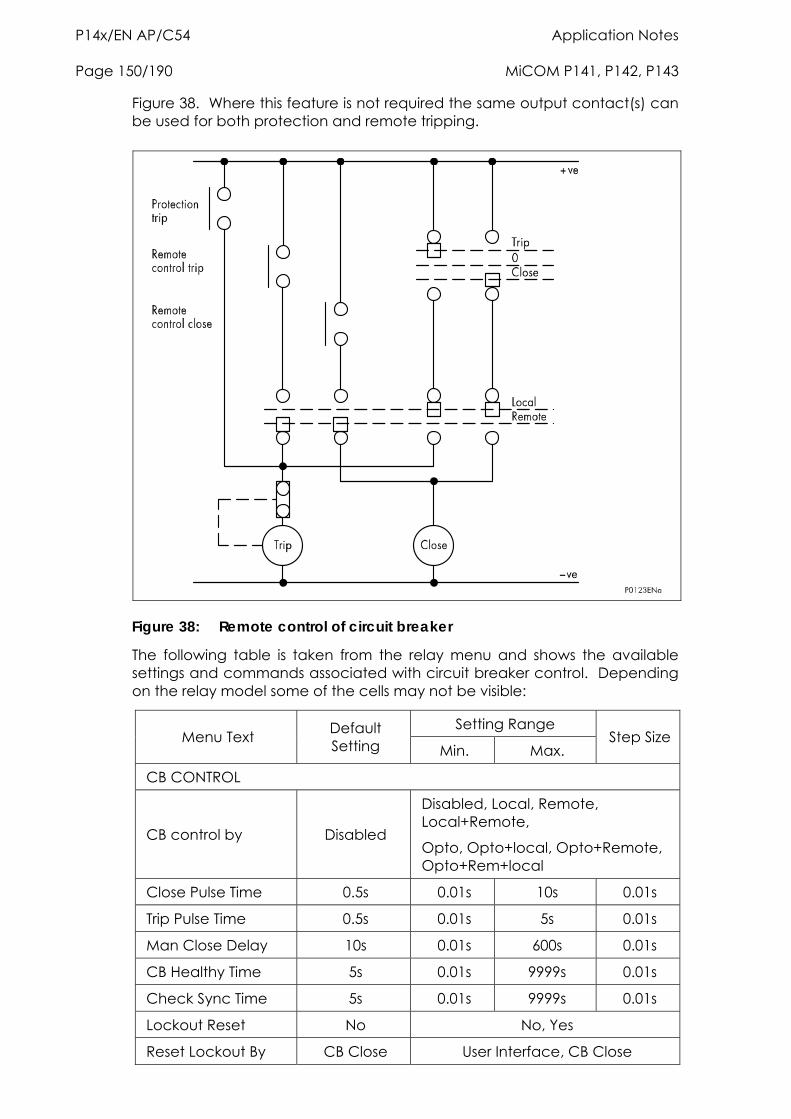
P14x/EN AP/C54 Application Notes Page 150/190 MiCOM P141, P142, P143
Figure 38. Where this feature is not required the same output contact(s) can be used for both protection and remote tripping.
Figure 38: Remote control of circuit breaker
The following table is taken from the relay menu and shows the available settings and commands associated with circuit breaker control. Depending on the relay model some of the cells may not be visible:
Setting Range Menu Text Default
Setting Min. Max. Step Size
CB CONTROL
CB control by Disabled
Disabled, Local, Remote, Local+Remote,
Opto, Opto+local, Opto+Remote, Opto+Rem+local
Close Pulse Time 0.5s 0.01s 10s 0.01s
Trip Pulse Time 0.5s 0.01s 5s 0.01s
Man Close Delay 10s 0.01s 600s 0.01s
CB Healthy Time 5s 0.01s 9999s 0.01s
Check Sync Time 5s 0.01s 9999s 0.01s
Lockout Reset No No, Yes
Reset Lockout By CB Close User Interface, CB Close
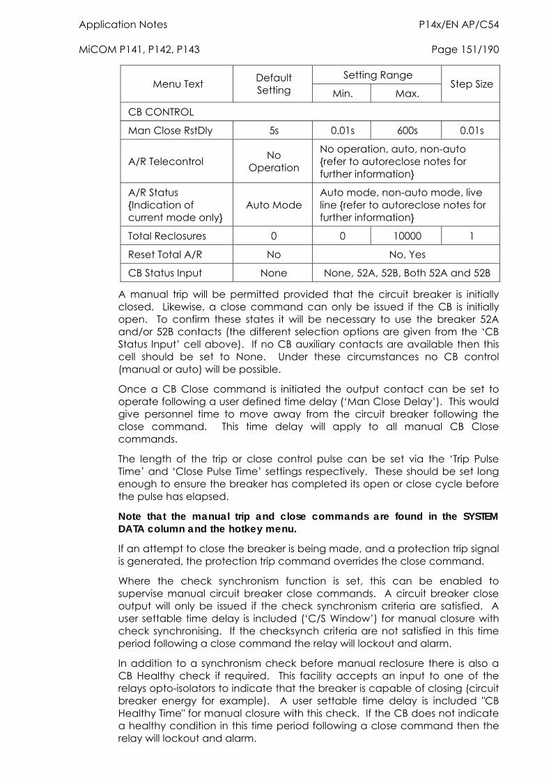
Application Notes P14x/EN AP/C54 MiCOM P141, P142, P143 Page 151/190
Setting Range Menu Text Default
Setting Min. Max. Step Size
CB CONTROL
Man Close RstDly 5s 0.01s 600s 0.01s
A/R Telecontrol No Operation
No operation, auto, non-auto {refer to autoreclose notes for further information}
A/R Status {Indication of current mode only}
Auto Mode Auto mode, non-auto mode, live line {refer to autoreclose notes for further information}
Total Reclosures 0 0 10000 1
Reset Total A/R No No, Yes
CB Status Input None None, 52A, 52B, Both 52A and 52B
A manual trip will be permitted provided that the circuit breaker is initially closed. Likewise, a close command can only be issued if the CB is initially open. To confirm these states it will be necessary to use the breaker 52A and/or 52B contacts (the different selection options are given from the ‘CB Status Input’ cell above). If no CB auxiliary contacts are available then this cell should be set to None. Under these circumstances no CB control (manual or auto) will be possible.
Once a CB Close command is initiated the output contact can be set to operate following a user defined time delay (‘Man Close Delay’). This would give personnel time to move away from the circuit breaker following the close command. This time delay will apply to all manual CB Close commands.
The length of the trip or close control pulse can be set via the ‘Trip Pulse Time’ and ‘Close Pulse Time’ settings respectively. These should be set long enough to ensure the breaker has completed its open or close cycle before the pulse has elapsed.
Note that the manual trip and close commands are found in the SYSTEM DATA column and the hotkey menu.
If an attempt to close the breaker is being made, and a protection trip signal is generated, the protection trip command overrides the close command.
Where the check synchronism function is set, this can be enabled to supervise manual circuit breaker close commands. A circuit breaker close output will only be issued if the check synchronism criteria are satisfied. A user settable time delay is included (‘C/S Window’) for manual closure with check synchronising. If the checksynch criteria are not satisfied in this time period following a close command the relay will lockout and alarm.
In addition to a synchronism check before manual reclosure there is also a CB Healthy check if required. This facility accepts an input to one of the relays opto-isolators to indicate that the breaker is capable of closing (circuit breaker energy for example). A user settable time delay is included "CB Healthy Time" for manual closure with this check. If the CB does not indicate a healthy condition in this time period following a close command then the relay will lockout and alarm.
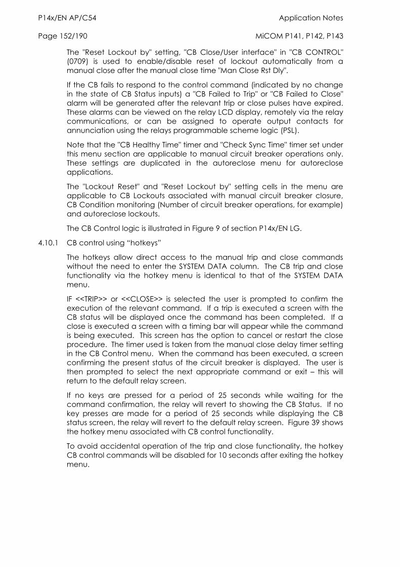
P14x/EN AP/C54 Application Notes Page 152/190 MiCOM P141, P142, P143
The "Reset Lockout by" setting, "CB Close/User interface" in "CB CONTROL" (0709) is used to enable/disable reset of lockout automatically from a manual close after the manual close time "Man Close Rst Dly".
If the CB fails to respond to the control command (indicated by no change in the state of CB Status inputs) a "CB Failed to Trip" or "CB Failed to Close" alarm will be generated after the relevant trip or close pulses have expired. These alarms can be viewed on the relay LCD display, remotely via the relay communications, or can be assigned to operate output contacts for annunciation using the relays programmable scheme logic (PSL).
Note that the "CB Healthy Time" timer and "Check Sync Time" timer set under this menu section are applicable to manual circuit breaker operations only. These settings are duplicated in the autoreclose menu for autoreclose applications.
The "Lockout Reset" and "Reset Lockout by" setting cells in the menu are applicable to CB Lockouts associated with manual circuit breaker closure, CB Condition monitoring (Number of circuit breaker operations, for example) and autoreclose lockouts.
The CB Control logic is illustrated in Figure 9 of section P14x/EN LG.
4.10.1 CB control using “hotkeys”
The hotkeys allow direct access to the manual trip and close commands without the need to enter the SYSTEM DATA column. The CB trip and close functionality via the hotkey menu is identical to that of the SYSTEM DATA menu.
IF <<TRIP>> or <<CLOSE>> is selected the user is prompted to confirm the execution of the relevant command. If a trip is executed a screen with the CB status will be displayed once the command has been completed. If a close is executed a screen with a timing bar will appear while the command is being executed. This screen has the option to cancel or restart the close procedure. The timer used is taken from the manual close delay timer setting in the CB Control menu. When the command has been executed, a screen confirming the present status of the circuit breaker is displayed. The user is then prompted to select the next appropriate command or exit – this will return to the default relay screen.
If no keys are pressed for a period of 25 seconds while waiting for the command confirmation, the relay will revert to showing the CB Status. If no key presses are made for a period of 25 seconds while displaying the CB status screen, the relay will revert to the default relay screen. Figure 39 shows the hotkey menu associated with CB control functionality.
To avoid accidental operation of the trip and close functionality, the hotkey CB control commands will be disabled for 10 seconds after exiting the hotkey menu.
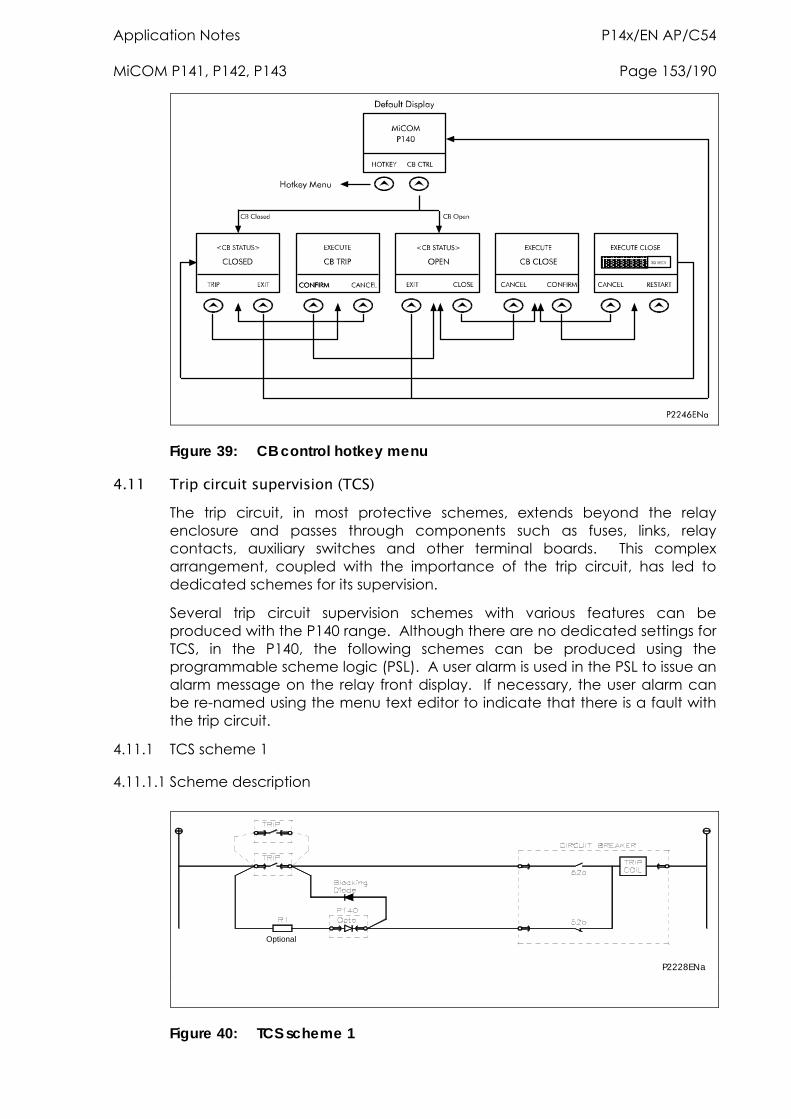
Application Notes P14x/EN AP/C54 MiCOM P141, P142, P143 Page 153/190
Figure 39: CB control hotkey menu
4.11 Trip circuit supervision (TCS) The trip circuit, in most protective schemes, extends beyond the relay enclosure and passes through components such as fuses, links, relay contacts, auxiliary switches and other terminal boards. This complex arrangement, coupled with the importance of the trip circuit, has led to dedicated schemes for its supervision.
Several trip circuit supervision schemes with various features can be produced with the P140 range. Although there are no dedicated settings for TCS, in the P140, the following schemes can be produced using the programmable scheme logic (PSL). A user alarm is used in the PSL to issue an alarm message on the relay front display. If necessary, the user alarm can be re-named using the menu text editor to indicate that there is a fault with the trip circuit.
4.11.1 TCS scheme 1
4.11.1.1 Scheme description
P2228ENa
Optional
Figure 40: TCS scheme 1
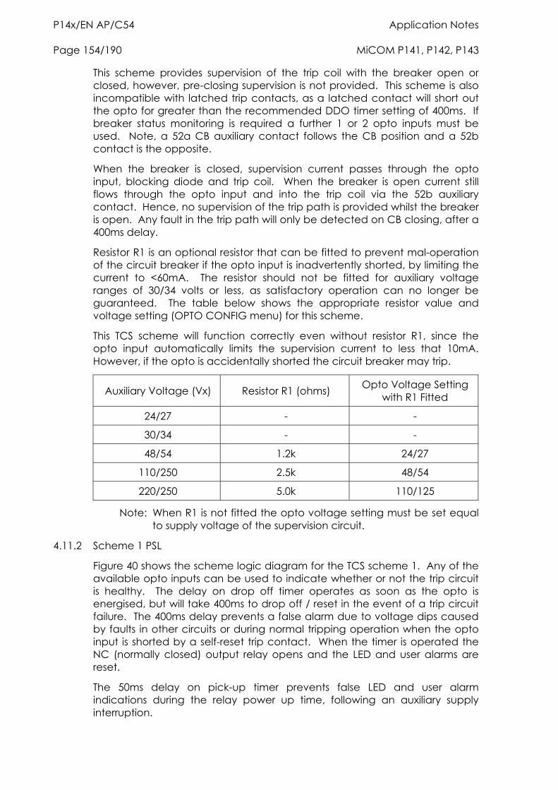
P14x/EN AP/C54 Application Notes Page 154/190 MiCOM P141, P142, P143
This scheme provides supervision of the trip coil with the breaker open or closed, however, pre-closing supervision is not provided. This scheme is also incompatible with latched trip contacts, as a latched contact will short out the opto for greater than the recommended DDO timer setting of 400ms. If breaker status monitoring is required a further 1 or 2 opto inputs must be used. Note, a 52a CB auxiliary contact follows the CB position and a 52b contact is the opposite.
When the breaker is closed, supervision current passes through the opto input, blocking diode and trip coil. When the breaker is open current still flows through the opto input and into the trip coil via the 52b auxiliary contact. Hence, no supervision of the trip path is provided whilst the breaker is open. Any fault in the trip path will only be detected on CB closing, after a 400ms delay.
Resistor R1 is an optional resistor that can be fitted to prevent mal-operation of the circuit breaker if the opto input is inadvertently shorted, by limiting the current to <60mA. The resistor should not be fitted for auxiliary voltage ranges of 30/34 volts or less, as satisfactory operation can no longer be guaranteed. The table below shows the appropriate resistor value and voltage setting (OPTO CONFIG menu) for this scheme.
This TCS scheme will function correctly even without resistor R1, since the opto input automatically limits the supervision current to less that 10mA. However, if the opto is accidentally shorted the circuit breaker may trip.
Auxiliary Voltage (Vx) Resistor R1 (ohms) Opto Voltage Setting with R1 Fitted
24/27 - -
30/34 - -
48/54 1.2k 24/27
110/250 2.5k 48/54
220/250 5.0k 110/125
Note: When R1 is not fitted the opto voltage setting must be set equal to supply voltage of the supervision circuit.
4.11.2 Scheme 1 PSL
Figure 40 shows the scheme logic diagram for the TCS scheme 1. Any of the available opto inputs can be used to indicate whether or not the trip circuit is healthy. The delay on drop off timer operates as soon as the opto is energised, but will take 400ms to drop off / reset in the event of a trip circuit failure. The 400ms delay prevents a false alarm due to voltage dips caused by faults in other circuits or during normal tripping operation when the opto input is shorted by a self-reset trip contact. When the timer is operated the NC (normally closed) output relay opens and the LED and user alarms are reset.
The 50ms delay on pick-up timer prevents false LED and user alarm indications during the relay power up time, following an auxiliary supply interruption.
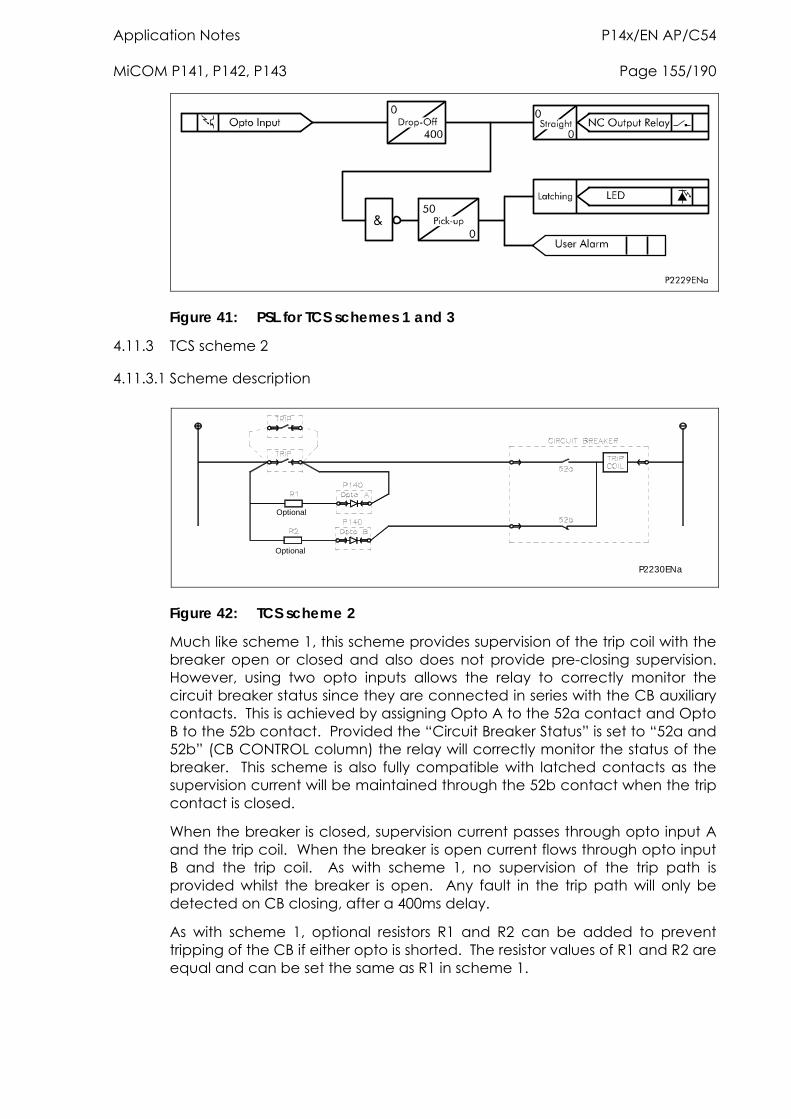
Application Notes P14x/EN AP/C54 MiCOM P141, P142, P143 Page 155/190
Figure 41: PSL for TCS schemes 1 and 3
4.11.3 TCS scheme 2
4.11.3.1 Scheme description
Optional
Optional
P2230ENa
Figure 42: TCS scheme 2
Much like scheme 1, this scheme provides supervision of the trip coil with the breaker open or closed and also does not provide pre-closing supervision. However, using two opto inputs allows the relay to correctly monitor the circuit breaker status since they are connected in series with the CB auxiliary contacts. This is achieved by assigning Opto A to the 52a contact and Opto B to the 52b contact. Provided the “Circuit Breaker Status” is set to “52a and 52b” (CB CONTROL column) the relay will correctly monitor the status of the breaker. This scheme is also fully compatible with latched contacts as the supervision current will be maintained through the 52b contact when the trip contact is closed.
When the breaker is closed, supervision current passes through opto input A and the trip coil. When the breaker is open current flows through opto input B and the trip coil. As with scheme 1, no supervision of the trip path is provided whilst the breaker is open. Any fault in the trip path will only be detected on CB closing, after a 400ms delay.
As with scheme 1, optional resistors R1 and R2 can be added to prevent tripping of the CB if either opto is shorted. The resistor values of R1 and R2 are equal and can be set the same as R1 in scheme 1.
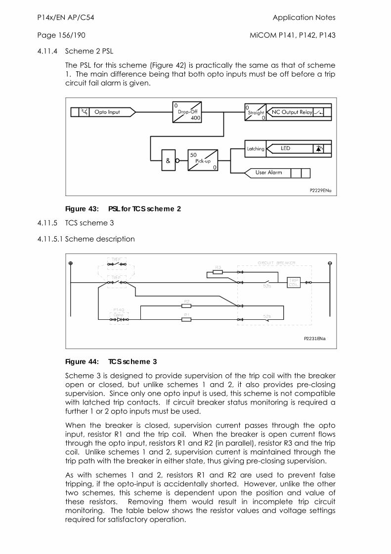
P14x/EN AP/C54 Application Notes Page 156/190 MiCOM P141, P142, P143
4.11.4 Scheme 2 PSL
The PSL for this scheme (Figure 42) is practically the same as that of scheme 1. The main difference being that both opto inputs must be off before a trip circuit fail alarm is given.
Figure 43: PSL for TCS scheme 2
4.11.5 TCS scheme 3
4.11.5.1 Scheme description
P2231ENa
Figure 44: TCS scheme 3
Scheme 3 is designed to provide supervision of the trip coil with the breaker open or closed, but unlike schemes 1 and 2, it also provides pre-closing supervision. Since only one opto input is used, this scheme is not compatible with latched trip contacts. If circuit breaker status monitoring is required a further 1 or 2 opto inputs must be used.
When the breaker is closed, supervision current passes through the opto input, resistor R1 and the trip coil. When the breaker is open current flows through the opto input, resistors R1 and R2 (in parallel), resistor R3 and the trip coil. Unlike schemes 1 and 2, supervision current is maintained through the trip path with the breaker in either state, thus giving pre-closing supervision.
As with schemes 1 and 2, resistors R1 and R2 are used to prevent false tr -in lly sh ever, r two sc this schem pendent u position a e of these s. Removing em would resu in incomplete t circuit monito he table below shows the resistor alues and voltage settings require tisfactory oper ion.
ipping, if the optohemes,
put is accidentae is de
orted. Howpon the
unlike the othend valu
resistorring. T
th lt v
rip
d for sa at
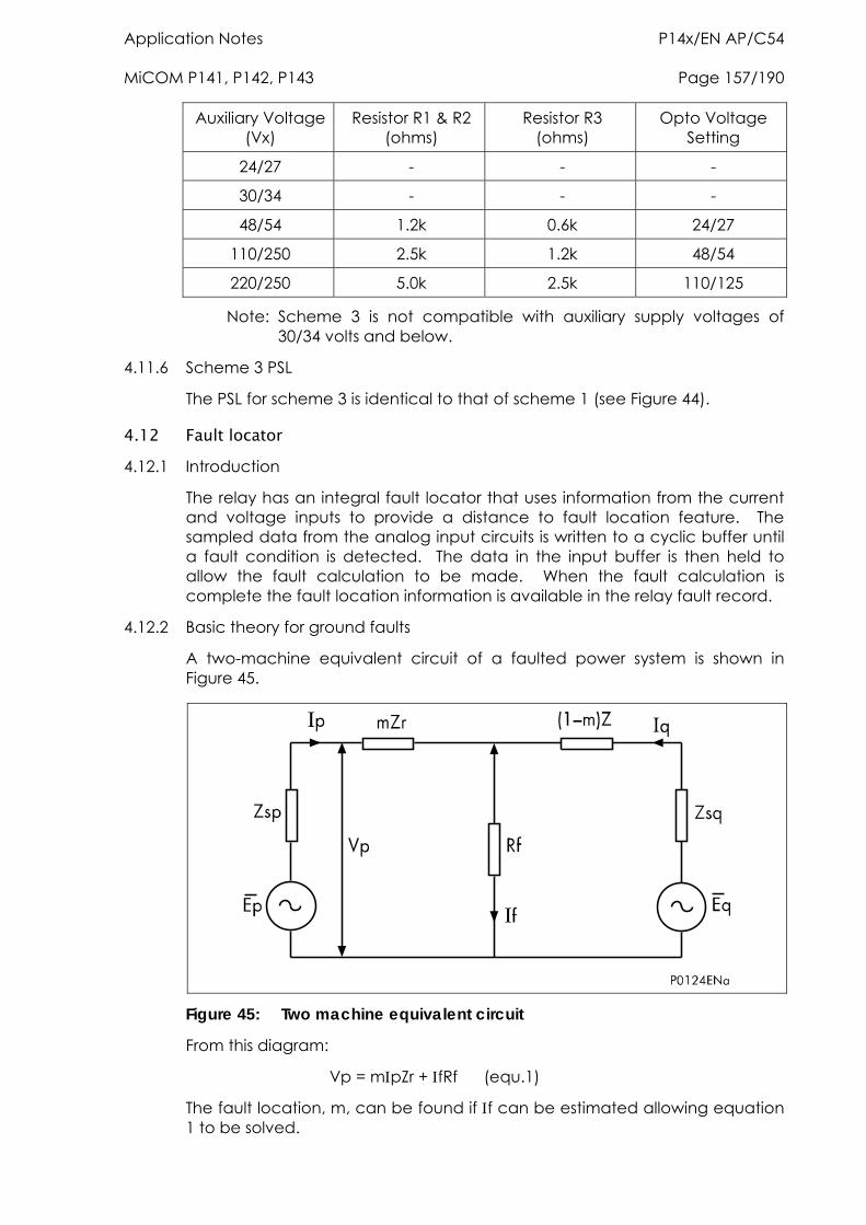
Application Notes P14x/EN AP/C54 MiCOM P141, P142, P143 Page 157/190
Auxilia age Resist & R2 (o
Re 3 (o
Opt ge S
ry Volt(Vx)
or R1 hms)
sistor Rhms)
o Voltaetting
24/27 - - -
30/34 - - -
48/5 0.6k 24/27 4 1.2k
110/250 2.5k 1.2k 48/54
220/250 5.0k 2.5k 110/125
Note: Sc30
heme 3 is not compatible with auxiliary supply voltages of /34 volts and below.
4.12
4.12.1
e a distance to fault location feature. The
fault calculation to be made. When the fault calculation is complete the fault location information is available in the relay fault record.
4.12.2 Basic theory for ground faults
A two-machine equivalent circuit of a faulted power system is shown in Figure 45.
4.11.6 Scheme 3 PSL
The PSL for scheme 3 is identical to that of scheme 1 (see Figure 44).
Fault locator Introduction
The relay has an integral fault locator that uses information from the currentand voltage inputs to providsampled data from the analog input circuits is written to a cyclic buffer until a fault condition is detected. The data in the input buffer is then held to allow the
Figure 45: Two machine equivalent circuit
From this diagram:
Vp = mpZr + fRf (equ.1)
The fault location, m, can be found if f can be estimated allowing equation 1 to be solved.
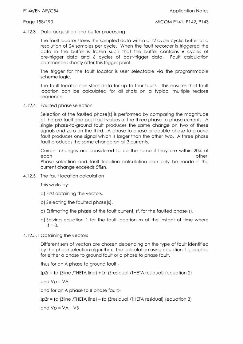
P14x/EN AP/C54 Application Notes Page 158/190 MiCOM P141, P142, P143
4.12.3 Data acquisition and buffer processing
The fault locator stores the sampled data within a 12 cycle cyclic buffer at a resolution of 24 samples per cycle. When the fault recorder is triggered the data in the buffer is frozen such that the buffer contains 6 cycles of pre-trigger data and 6 cycles of post-trigger data. Fault calculation commences shortly after this trigger point.
The trigger for the fault locator is user selectable via the programmable scheme logic.
The fault locator can store data for up to four faults. This ensures that fault location can be calculated for all shots on a typical multiple reclose sequence.
4.12.4 Faulted phase selection
Selection of the faulted phase(s) is performed by comparing the magnitude of the pre-fault and post fault values of the three phase-to-phase currents. A single phase-to-ground fault produces the same change on two of these signals and zero on the third. A phase-to-phase or double phase-to-ground fault produces one signal which is larger than the other two. A three phase fault produces the same change on all 3 currents.
Current changes are considered to be the same if they are within 20% of each other. Phase selection and fault location calculation can only be made if the current change exceeds 5%n.
4.12.5 The fault location calculation
This works by:
a) First obtaining the vectors.
b) Selecting the faulted phase(s).
c) Estimating the phase of the fault current, f, for the faulted phase(s).
d) Solving equation 1 for the fault location m at the instant of time where f = 0.
4.12.5.1 Obtaining the vectors
Different sets of vectors are chosen depending on the type of fault identified by the phase selection algorithm. The calculation using equation 1 is applied for either a phase to ground fault or a phase to phase fault.
thus for an A phase to ground fault:-
pZr = a (Zline /THETA line) + n (Zresidual /THETA residual) (equation 2)
and Vp = VA
and for an A phase to B phase fault:-
pZr = a (Zline /THETA line) – b (Zresidual /THETA residual) (equation 3)
and Vp = VA – VB
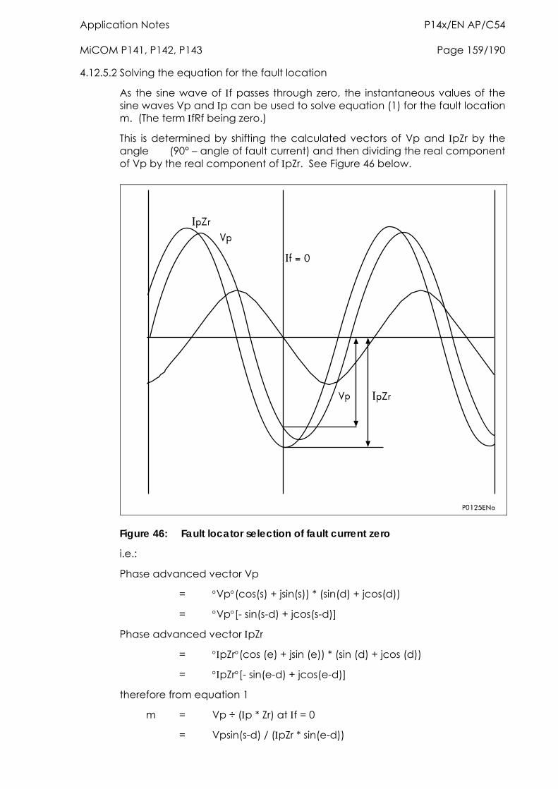
Application Notes P14x/EN AP/C54 MiCOM P141, P142, P143 Page 159/190
4.12.5.2 Solving the equation for the fault location
As the sine wave of f passes through zero, the instantaneous values of the sine waves Vp and p can be used to solve equation (1) for the fault location m. (The term fRf being zero.)
This is determined by shifting the calculated vectors of Vp and pZr by the angle (90° – angle of fault current) and then dividing the real component of Vp by the real component of pZr. See Figure 46 below.
Figure 46: Fault locator selection of fault current zero
i.e.:
Phase advanced vector Vp
= Vp(cos(s) + jsin(s)) * (sin(d) + jcos(d))
= Vp[- sin(s-d) + jcos(s-d)]
Phase advanced vector pZr
= pZr(cos (e) + jsin (e)) * (sin (d) + jcos (d))
= pZr[- sin(e-d) + jcos(e-d)]
therefore from equation 1
m = Vp ÷ (p * Zr) at f = 0
= Vpsin(s-d) / (pZr * sin(e-d))
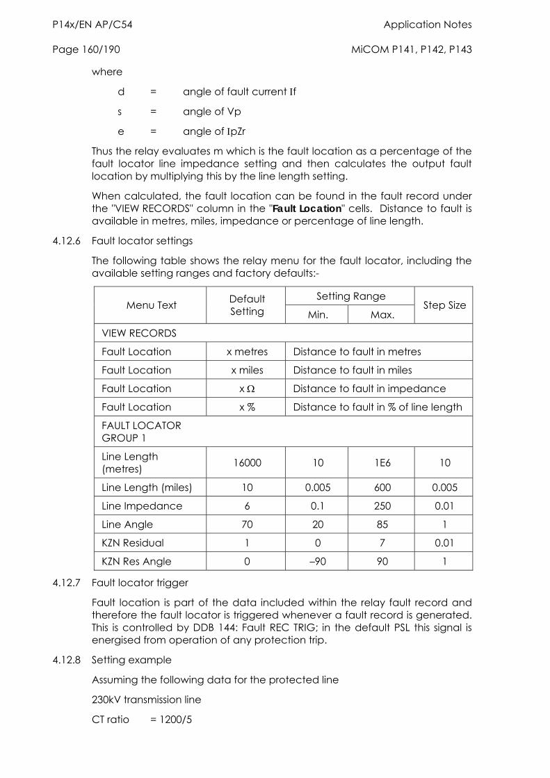
P14x/EN AP/C54 Application Notes Page 160/190 MiCOM P141, P142, P143
where
d = angle of fault current f
s = angle of Vp
e = angle of pZr
Thus the relay evaluates m which is the fault location as a percentage of the fault locator line impedance setting and then calculates the output fault location by multiplying this by the line length setting.
When calculated, the fault location can be found in the fault record under the "VIEW RECORDS" column in the "Fault Location" cells. Distance to fault is available in metres, miles, impedance or percentage of line length.
4.12.6 Fault locator settings
The following table shows the relay menu for the fault locator, including the available setting ranges and factory defaults:-
Setting Range Menu Text Default
Setting Min. Max. Step Size
VIEW RECORDS
Fault Location x metres Distance to fault in metres
Fault Location x miles Distance to fault in miles
Fault Location x Distance to fault in impedance
Fault Location x % Distance to fault in % of line length
FAULT LOCATOR GROUP 1
Line Length (metres) 16000 10 1E6 10
Line Length (miles) 10 0.005 600 0.005
Line Impedance 6 0.1 250 0.01
Line Angle 70 20 85 1
KZN Residual 1 0 7 0.01
KZN Res Angle 0 –90 90 1
4.12.7 Fault locator trigger
Fault location is part of the data included within the relay fault record and therefore the fault locator is triggered whenever a fault record is generated. This is controlled by DDB 144: Fault REC TRIG; in the default PSL this signal is energised from operation of any protection trip.
4.12.8 Setting example
Assuming the following data for the protected line
230kV transmission line
CT ratio = 1200/5
Application Notes P14x/EN AP/C54 MiCOM P141, P142, P143 Page 161/190
VT ratio = 230,000/115
Line length = 10km
Positive sequence line impedance ZL1 = 0.089+j0.476 Ohms/km
Zero sequence line impedance ZL0 = 0.34+j1.03 ohms/km
Zero sequence mutual impedance ZM0 = 0.1068+j0.5712 Ohms/km
The line length can be set in either metres or miles.
Therefore for this example set line length = 10km.
The line impedance magnitude and angle settings are calculated as follows:
Ratio of secondary to primary impedance = CT ratio/VT ratio = 0.12
Positive sequence line impedance ZL1 = 0.12 x 10(0.48479.4°) = 0.58 79.4°
Therefore set line length = 0.58
Line angle = 79°
The residual impedance compensation magnitude and angle are calculated using the following formula:
KZn = ZL0 - ZL1
3 ZL1
= (0.34 + j1.03) – (0.089 + j0.476)
3 x (0.484 79.4)
= 0.6 65.2
1.45 79.4
= 0.41 -14.2° Therefore set kZn Residual = 0.41
kZn Res Angle = -14°
4.13 Event & fault records The relay records and time tags up to 512 events and stores them in non-volatile (battery backed up) memory. This enables the system operator to establish the sequence of events that occurred within the relay following a particular power system condition, switching sequence etc. When the available space is exhausted, the oldest event is automatically overwritten by the new one.
The real time clock within the relay provides the time tag to each event, to a resolution of 1ms.
The event records are available for viewing either via the frontplate LCD or remotely, via the communications ports (courier and MODBUS versions only).
Local viewing on the LCD is achieved in the menu column entitled "VIEW RECORDS". This column allows viewing of event, fault and maintenance records and is shown the following table:
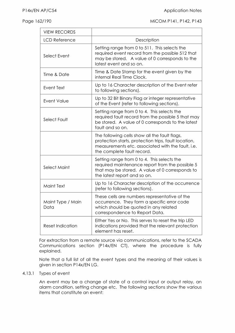
P14x/EN AP/C54 Application Notes Page 162/190 MiCOM P141, P142, P143
VIEW RECORDS
LCD Reference Description
Select Event
Setting range from 0 to 511. This selects the required event record from the possible 512 that may be stored. A value of 0 corresponds to the latest event and so on.
Time & Date Time & Date Stamp for the event given by the internal Real Time Clock.
Event Text Up to 16 Character description of the Event refer to following sections).
Event Value Up to 32 Bit Binary Flag or integer representative of the Event (refer to following sections).
Select Fault
Setting range from 0 to 4. This selects the required fault record from the possible 5 that may be stored. A value of 0 corresponds to the latest fault and so on.
The following cells show all the fault flags, protection starts, protection trips, fault location, measurements etc. associated with the fault, i.e. the complete fault record.
Select Maint
Setting range from 0 to 4. This selects the required maintenance report from the possible 5 that may be stored. A value of 0 corresponds to the latest report and so on.
Maint Text Up to 16 Character description of the occurrence (refer to following sections).
Maint Type / Main Data
These cells are numbers representative of the occurrence. They form a specific error code which should be quoted in any related correspondence to Report Data.
Reset Indication Either Yes or No. This serves to reset the trip LED indications provided that the relevant protection element has reset.
For extraction from a remote source via communications, refer to the SCADA Communications section (P14x/EN CT), where the procedure is fully explained.
Note that a full list of all the event types and the meaning of their values is given in section P14x/EN LG.
4.13.1 Types of event
An event may be a change of state of a control input or output relay, an alarm condition, setting change etc. The following sections show the various items that constitute an event:
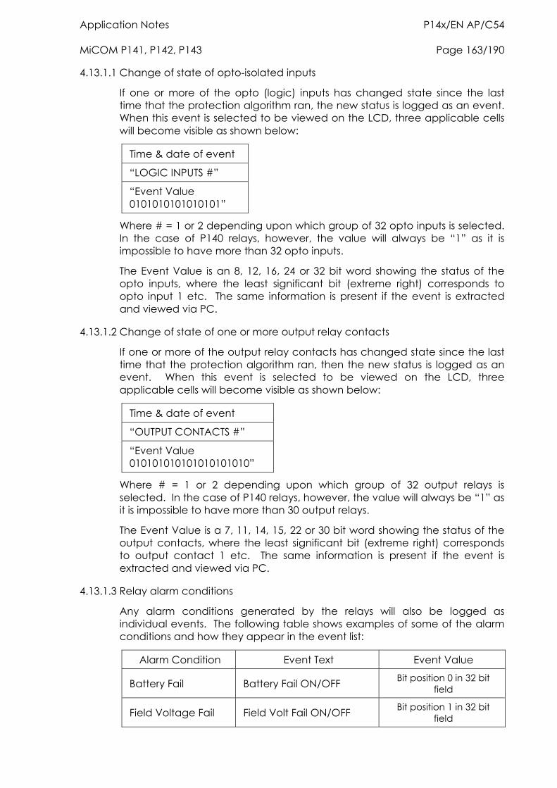
Application Notes P14x/EN AP/C54 MiCOM P141, P142, P143 Page 163/190
4.13.1.1 Change of state of opto-isolated inputs
If one or more of the opto (logic) inputs has changed state since the last time that the protection algorithm ran, the new status is logged as an event. When this event is selected to be viewed on the LCD, three applicable cells will become visible as shown below:
Time & date of event
“LOGIC INPUTS #”
“Event Value 0101010101010101”
Where # = 1 or 2 depending upon which group of 32 opto inputs is selected. In the case of P140 relays, however, the value will always be “1” as it is impossible to have more than 32 opto inputs.
The Event Value is an 8, 12, 16, 24 or 32 bit word showing the status of the opto inputs, where the least significant bit (extreme right) corresponds to opto input 1 etc. The same information is present if the event is extracted and viewed via PC.
4.13.1.2 Change of state of one or more output relay contacts
If one or more of the output relay contacts has changed state since the last time that the protection algorithm ran, then the new status is logged as an event. When this event is selected to be viewed on the LCD, three applicable cells will become visible as shown below:
Time & date of event
“OUTPUT CONTACTS #”
“Event Value 010101010101010101010”
Where # = 1 or 2 depending upon which group of 32 output relays is selected. In the case of P140 relays, however, the value will always be “1” as it is impossible to have more than 30 output relays.
The Event Value is a 7, 11, 14, 15, 22 or 30 bit word showing the status of the output contacts, where the least significant bit (extreme right) corresponds to output contact 1 etc. The same information is present if the event is extracted and viewed via PC.
4.13.1.3 Relay alarm conditions
Any alarm conditions generated by the relays will also be logged as individual events. The following table shows examples of some of the alarm conditions and how they appear in the event list:
Alarm Condition Event Text Event Value
Battery Fail Battery Fail ON/OFF Bit position 0 in 32 bit field
Field Voltage Fail Field Volt Fail ON/OFF Bit position 1 in 32 bit field
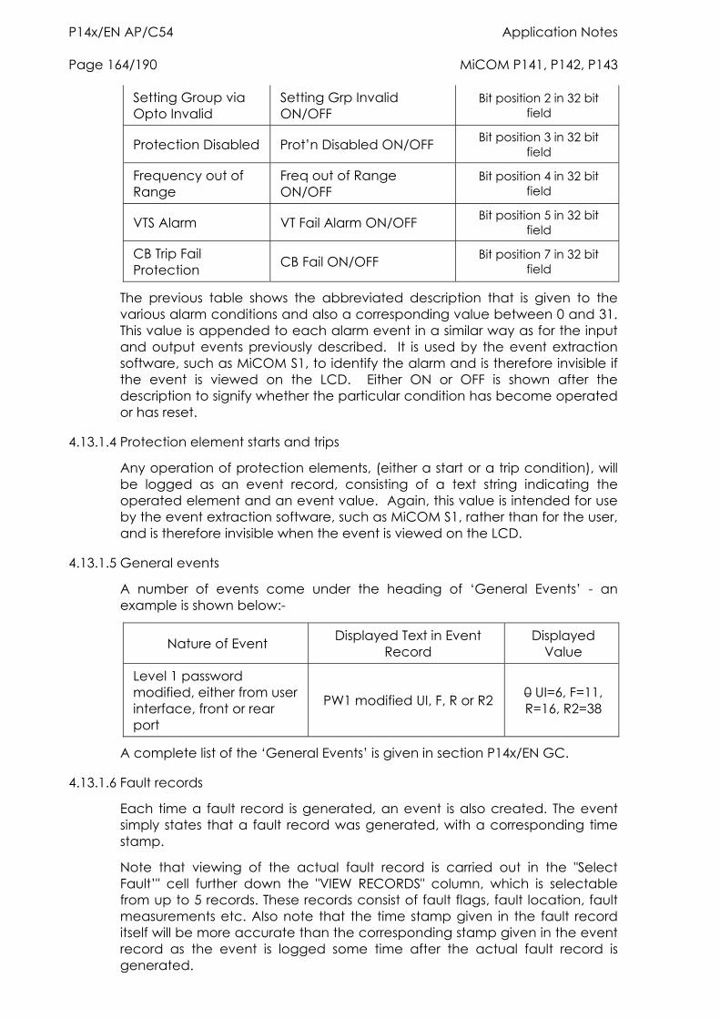
P14x/EN AP/C54 Application Notes Page 164/190 MiCOM P141, P142, P143
Setting Group via Opto Invalid
Setting Grp Invalid ON/OFF
Bit position 2 in 32 bit field
Protection Disabled Prot’n Disabled ON/OFF Bit position 3 in 32 bit field
Frequency out of Range
Freq out of Range ON/OFF
Bit position 4 in 32 bit field
VTS Alarm VT Fail Alarm ON/OFF Bit position 5 in 32 bit field
CB Trip Fail Protection CB Fail ON/OFF Bit position 7 in 32 bit
field
The previous table shows the abbreviated description that is given to the various alarm conditions and also a corresponding value between 0 and 31. This value is appended to each alarm event in a similar way as for the input and output events previously described. It is used by the event extraction software, such as MiCOM S1, to identify the alarm and is therefore invisible if the event is viewed on the LCD. Either ON or OFF is shown after the description to signify whether the particular condition has become operated or has reset.
4.13.1.4 Protection element starts and trips
Any operation of protection elements, (either a start or a trip condition), will be logged as an event record, consisting of a text string indicating the operated element and an event value. Again, this value is intended for use by the event extraction software, such as MiCOM S1, rather than for the user, and is therefore invisible when the event is viewed on the LCD.
4.13.1.5 General events
A number of events come under the heading of ‘General Events’ - an example is shown below:-
Nature of Event Displayed Text in Event Record
Displayed Value
Level 1 password modified, either from user interface, front or rear port
PW1 modified UI, F, R or R2 0 UI=6, F=11, R=16, R2=38
A complete list of the ‘General Events’ is given in section P14x/EN GC.
4.13.1.6 Fault records
Each time a fault record is generated, an event is also created. The event simply states that a fault record was generated, with a corresponding time stamp.
Note that viewing of the actual fault record is carried out in the "Select Fault’" cell further down the "VIEW RECORDS" column, which is selectable from up to 5 records. These records consist of fault flags, fault location, fault measurements etc. Also note that the time stamp given in the fault record itself will be more accurate than the corresponding stamp given in the event record as the event is logged some time after the actual fault record is generated.
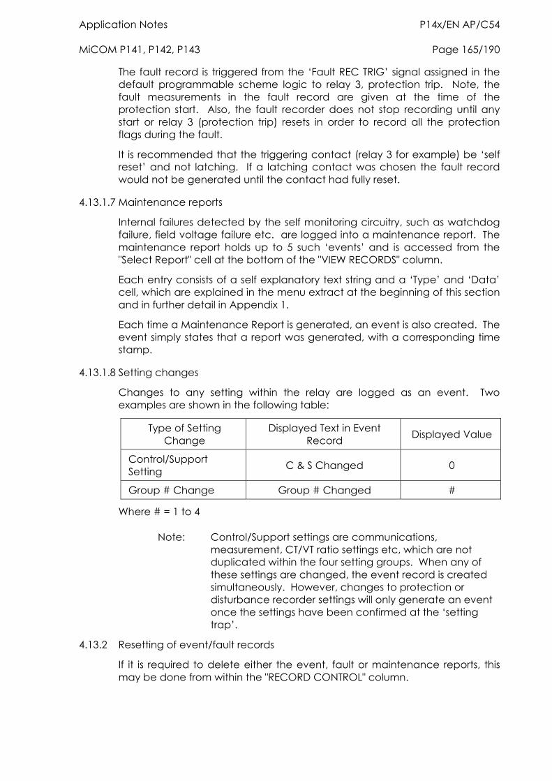
Application Notes P14x/EN AP/C54 MiCOM P141, P142, P143 Page 165/190
The fault record is triggered from the ‘Fault REC TRIG’ signal assigned in the default programmable scheme logic to relay 3, protection trip. Note, the fault measurements in the fault record are given at the time of the protection start. Also, the fault recorder does not stop recording until any start or relay 3 (protection trip) resets in order to record all the protection flags during the fault.
It is recommended that the triggering contact (relay 3 for example) be ‘self reset’ and not latching. If a latching contact was chosen the fault record would not be generated until the contact had fully reset.
4.13.1.7 Maintenance reports
Internal failures detected by the self monitoring circuitry, such as watchdog failure, field voltage failure etc. are logged into a maintenance report. The maintenance report holds up to 5 such ‘events’ and is accessed from the "Select Report" cell at the bottom of the "VIEW RECORDS" column.
Each entry consists of a self explanatory text string and a ‘Type’ and ‘Data’ cell, which are explained in the menu extract at the beginning of this section and in further detail in Appendix 1.
Each time a Maintenance Report is generated, an event is also created. The event simply states that a report was generated, with a corresponding time stamp.
4.13.1.8 Setting changes
Changes to any setting within the relay are logged as an event. Two examples are shown in the following table:
Type of Setting Change
Displayed Text in Event Record Displayed Value
Control/Support Setting C & S Changed 0
Group # Change Group # Changed #
Where # = 1 to 4
Note: Control/Support settings are communications, measurement, CT/VT ratio settings etc, which are not duplicated within the four setting groups. When any of these settings are changed, the event record is created simultaneously. However, changes to protection or disturbance recorder settings will only generate an event once the settings have been confirmed at the ‘setting trap’.
4.13.2 Resetting of event/fault records
If it is required to delete either the event, fault or maintenance reports, this may be done from within the "RECORD CONTROL" column.
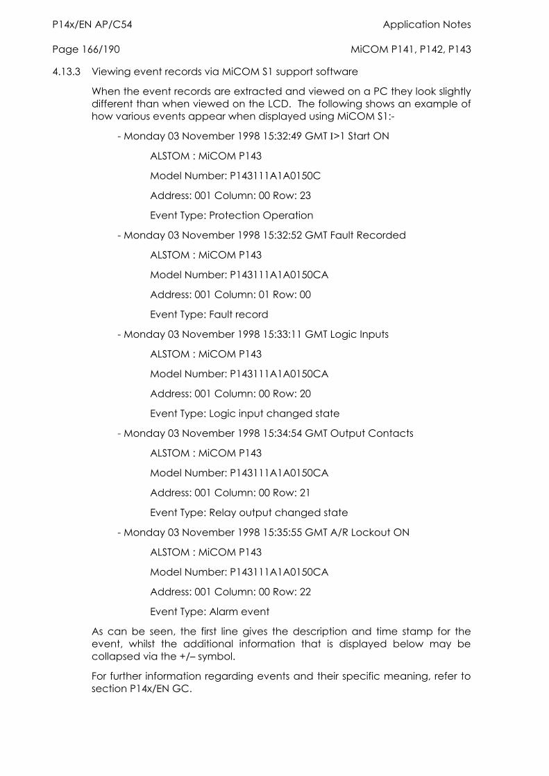
P14x/EN AP/C54 Application Notes Page 166/190 MiCOM P141, P142, P143
4.13.3 Viewing event records via MiCOM S1 support software
When the event records are extracted and viewed on a PC they look slightly different than when viewed on the LCD. The following shows an example of how various events appear when displayed using MiCOM S1:-
- Monday 03 November 1998 15:32:49 GMT >1 Start ON
ALSTOM : MiCOM P143
Model Number: P143111A1A0150C
Address: 001 Column: 00 Row: 23
Event Type: Protection Operation
- Monday 03 November 1998 15:32:52 GMT Fault Recorded
ALSTOM : MiCOM P143
Model Number: P143111A1A0150CA
Address: 001 Column: 01 Row: 00
Event Type: Fault record
- Monday 03 November 1998 15:33:11 GMT Logic Inputs
ALSTOM : MiCOM P143
Model Number: P143111A1A0150CA
Address: 001 Column: 00 Row: 20
Event Type: Logic input changed state
- Monday 03 November 1998 15:34:54 GMT Output Contacts
ALSTOM : MiCOM P143
Model Number: P143111A1A0150CA
Address: 001 Column: 00 Row: 21
Event Type: Relay output changed state
- Monday 03 November 1998 15:35:55 GMT A/R Lockout ON
ALSTOM : MiCOM P143
Model Number: P143111A1A0150CA
Address: 001 Column: 00 Row: 22
Event Type: Alarm event
As can be seen, the first line gives the description and time stamp for the event, whilst the additional information that is displayed below may be collapsed via the +/– symbol.
For further information regarding events and their specific meaning, refer to section P14x/EN GC.
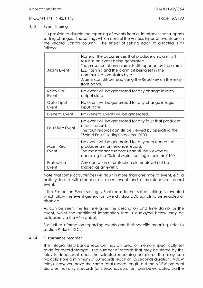
Application Notes P14x/EN AP/C54 MiCOM P141, P142, P143 Page 167/190
4.13.4 Event filtering
It is possible to disable the reporting of events from all interfaces that supports setting changes. The settings which control the various types of events are in the Record Control column. The effect of setting each to disabled is as follows:
Alarm Event
None of the occurrences that produce an alarm will result in an event being generated. The presence of any alarms is still reported by the alarm LED flashing and the alarm bit being set in the communications status byte. Alarms can still be read using the Read key on the relay front panel.
Relay O/P Event
No event will be generated for any change in relay output state.
Opto Input Event
No event will be generated for any change in logic input state.
General Event No General Events will be generated.
Fault Rec Event
No event will be generated for any fault that produces a fault record. The fault records can still be viewed by operating the “Select Fault” setting in column 0100.
Maint Rec Event
No event will be generated for any occurrence that produces a maintenance record. The maintenance records can still be viewed by operating the “Select Maint” setting in column 0100.
Protection Event
Any operation of protection elements will not be logged as an event.
Note that some occurrences will result in more than one type of event, e.g. a battery failure will produce an alarm event and a maintenance record event.
If the Protection Event setting is Enabled a further set of settings is revealed which allow the event generation by individual DDB signals to be enabled or disabled.
As can be seen, the first line gives the description and time stamp for the event, whilst the additional information that is displayed below may be collapsed via the +/– symbol.
For further information regarding events and their specific meaning, refer to section P14x/EN GC.
4.14 Disturbance recorder The integral disturbance recorder has an area of memory specifically set aside for record storage. The number of records that may be stored by the relay is dependent upon the selected recording duration. The relay can typically store a minimum of 50 records, each of 1.5 seconds duration. VDEW relays, however, have the same total record length but the VDEW protocol dictates that only 8 records (of 3 seconds duration) can be extracted via the
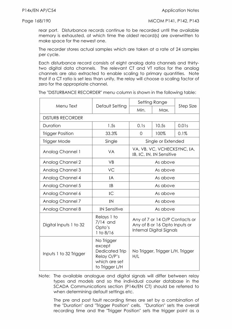
P14x/EN AP/C54 Application Notes Page 168/190 MiCOM P141, P142, P143
rear port. Disturbance records continue to be recorded until the available memory is exhausted, at which time the oldest record(s) are overwritten to make space for the newest one.
The recorder stores actual samples which are taken at a rate of 24 samples per cycle.
Each disturbance record consists of eight analog data channels and thirty-two digital data channels. The relevant CT and VT ratios for the analog channels are also extracted to enable scaling to primary quantities. Note that if a CT ratio is set less than unity, the relay will choose a scaling factor of zero for the appropriate channel.
The "DISTURBANCE RECORDER" menu column is shown in the following table:
Setting Range Menu Text Default Setting
Min. Max. Step Size
DISTURB RECORDER
Duration 1.5s 0.1s 10.5s 0.01s
Trigger Position 33.3% 0 100% 0.1%
Trigger Mode Single Single or Extended
Analog Channel 1 VA VA, VB, VC, VCHECKSYNC, A, B, C, N, N Sensitive
Analog Channel 2 VB As above
Analog Channel 3 VC As above
Analog Channel 4 A As above
Analog Channel 5 B As above
Analog Channel 6 C As above
Analog Channel 7 N As above
Analog Channel 8 N Sensitive As above
Digital Inputs 1 to 32
Relays 1 to 7/14 and Opto’s 1 to 8/16
Any of 7 or 14 O/P Contacts or Any of 8 or 16 Opto Inputs or Internal Digital Signals
Inputs 1 to 32 Trigger
No Trigger except Dedicated Trip Relay O/P’s which are set to Trigger L/H
No Trigger, Trigger L/H, Trigger H/L
Note: The available analogue and digital signals will differ between relay types and models and so the individual courier database in the SCADA Communications section (P14x/EN CT) should be referred to when determining default settings etc.
The pre and post fault recording times are set by a combination of the "Duration" and "Trigger Position" cells. "Duration" sets the overall recording time and the "Trigger Position" sets the trigger point as a
Application Notes P14x/EN AP/C54 MiCOM P141, P142, P143 Page 169/190
percentage of the duration. For example, the default settings show that the overall recording time is set to 1.5s with the trigger point being at 33.3% of this, giving 0.5s pre-fault and 1s post fault recording times.
If a further trigger occurs whilst a recording is taking place, the recorder will ignore the trigger if the "Trigger Mode" has been set to "Single". However, if this has been set to "Extended", the post trigger timer will be reset to zero, thereby extending the recording time.
As can be seen from the menu, each of the analog channels is selectable from the available analog inputs to the relay. The digital channels may be mapped to any of the opto isolated inputs or output contacts, in addition to a number of internal relay digital signals, such as protection starts, LED’s etc. The complete list of these signals may be found by viewing the available settings in the relay menu or via a setting file in MiCOM S1. Any of the digital channels may be selected to trigger the disturbance recorder on either a low to high or a high to low transition, via the "Input Trigger" cell. The default trigger settings are that any dedicated trip output contacts (e.g. relay 3) will trigger the recorder.
It is not possible to view the disturbance records locally via the LCD; they must be extracted using suitable software such as MiCOM S1. This process is fully explained in the SCADA Communications section (P14x/EN CT).
4.15 Measurements The relay produces a variety of both directly measured and calculated power system quantities. These measurement values are updated on a per second basis and are summarised below:
Phase Voltages and Currents
Phase to Phase Voltage and Currents
Sequence Voltages and Currents
Slip Frequency
Power and Energy Quantities
Rms. Voltages and Currents
Peak, Fixed and Rolling Demand Values
There are also measured values from the protection functions, which are also displayed under the measurement columns of the menu; these are described in the section on the relevant protection function.
4.15.1 Measured voltages and currents
The relay produces both phase to ground and phase to phase voltage and current values. They are produced directly from the DFT (Discrete Fourier Transform) used by the relay protection functions and present both magnitude and phase angle measurement.
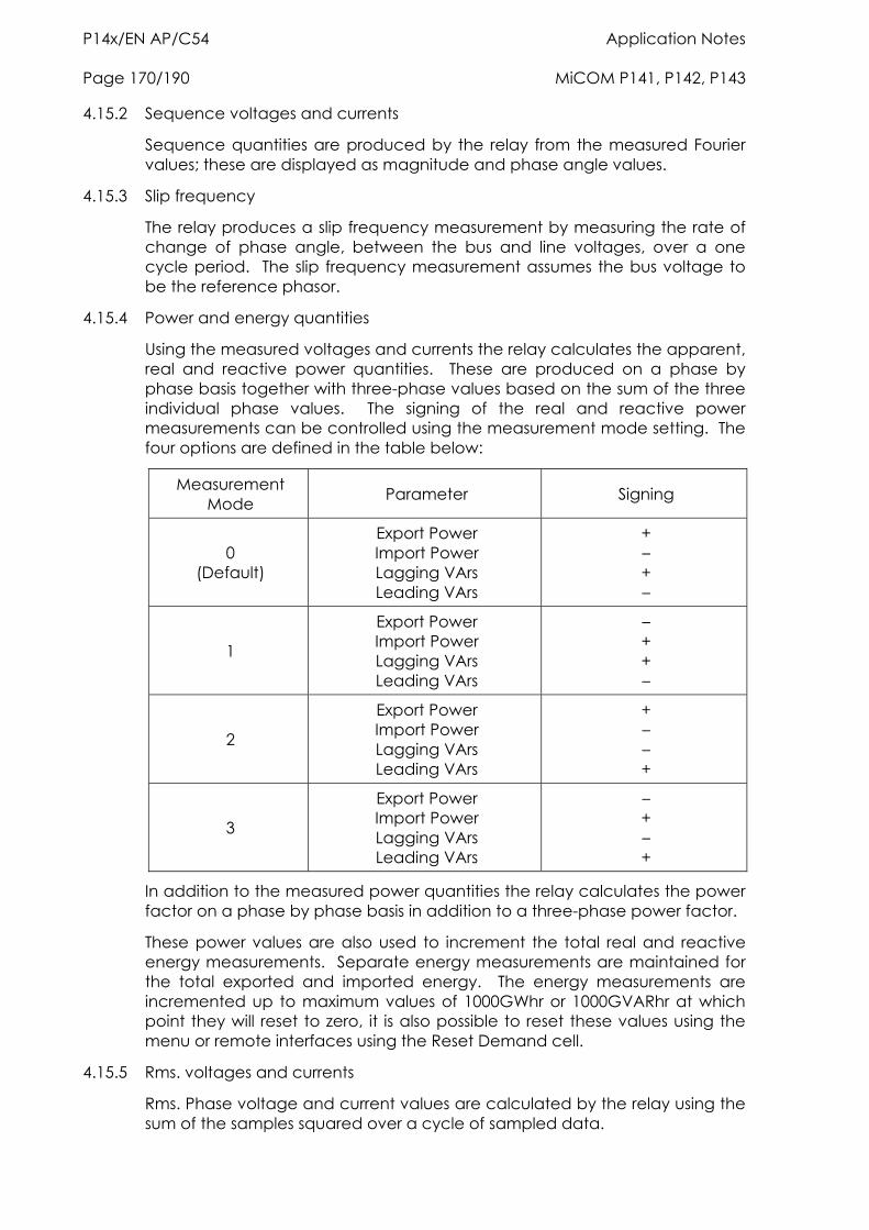
P14x/EN AP/C54 Application Notes Page 170/190 MiCOM P141, P142, P143
4.15.2 Sequence voltages and currents
Sequence quantities are produced by the relay from the measured Fourier values; these are displayed as magnitude and phase angle values.
4.15.3 Slip frequency
The relay produces a slip frequency measurement by measuring the rate of change of phase angle, between the bus and line voltages, over a one cycle period. The slip frequency measurement assumes the bus voltage to be the reference phasor.
4.15.4 Power and energy quantities
Using the measured voltages and currents the relay calculates the apparent, real and reactive power quantities. These are produced on a phase by phase basis together with three-phase values based on the sum of the three individual phase values. The signing of the real and reactive power measurements can be controlled using the measurement mode setting. The four options are defined in the table below:
Measurement Mode Parameter Signing
0 (Default)
Export Power Import Power Lagging VArs Leading VArs
+ – + –
1
Export Power Import Power Lagging VArs Leading VArs
– + + –
2
Export Power Import Power Lagging VArs Leading VArs
+ – – +
3
Export Power Import Power Lagging VArs Leading VArs
– + – +
In addition to the measured power quantities the relay calculates the power factor on a phase by phase basis in addition to a three-phase power factor.
These power values are also used to increment the total real and reactive energy measurements. Separate energy measurements are maintained for the total exported and imported energy. The energy measurements are incremented up to maximum values of 1000GWhr or 1000GVARhr at which point they will reset to zero, it is also possible to reset these values using the menu or remote interfaces using the Reset Demand cell.
4.15.5 Rms. voltages and currents
Rms. Phase voltage and current values are calculated by the relay using the sum of the samples squared over a cycle of sampled data.

Application Notes P14x/EN AP/C54 MiCOM P141, P142, P143 Page 171/190
4.15.6 Demand values
The relay produces fixed, rolling and peak demand values, using the Reset Demand menu cell it is possible to reset these quantities via the User Interface or the remote communications.
Fixed demand values
The fixed demand value is the average value of a quantity over the specified interval; values are produced for each phase current and for three phase real and reactive power. The fixed demand values displayed by the relay are those for the previous interval, the values are updated at the end of the fixed demand period.
Rolling demand values
The rolling demand values are similar to the fixed demand values, the difference being that a sliding window is used. The rolling demand window consists of a number of smaller sub-periods. The resolution of the sliding window is the sub-period length, with the displayed values being updated at the end of each of the sub-periods.
Peak demand values
Peak demand values are produced for each phase current and the real and reactive power quantities. These display the maximum value of the measured quantity since the last reset of the demand values.
4.15.7 Settings
The following settings under the heading Measurement Setup can be used to configure the relay measurement function.
MEASUREMENT SETUP Default Value Options/Limits
Default Display Description
Description/Plant Reference/ Frequency/Access Level/3Ph + N Current/3Ph Voltage/Power/Date and time
Local Values Primary Primary/Secondary
Remote Values Primary Primary/Secondary
Measurement Ref VA VA/VB/VC/A/B/C
Measurement Mode 0 0 to 3 step 1
Fix Dem Period 30 minutes 1 to 99 minutes step 1 minute
Roll Sub Period 30 minutes 1 to 99 minutes step 1 minute
Num Sub Periods 1 1 to 15 step 1
Distance Unit* km km/miles
Fault Location* Distance Distance/Ohms/% of Line
* Note: These settings are available for products with integral fault location.
Default display

P14x/EN AP/C54 Application Notes Page 172/190 MiCOM P141, P142, P143
This setting can be used to select the default display from a range of options, note that it is also possible to view the other default displays whilst at the default level using the and keys. However once the 15 minute timeout elapses the default display will revert to that selected by this setting.
Local values
This setting controls whether measured values via the front panel user interface and the front Courier port are displayed as primary or secondary quantities.
Remote values
This setting controls whether measured values via the rear communication port are displayed as primary or secondary quantities.
Measurement ref.
Using this setting the phase reference for all angular measurements by the relay can be selected.
Measurement mode
This setting is used to control the signing of the real and reactive power quantities; the signing convention used is defined in Section 4.15.4.
Fixed demand period
This setting defines the length of the fixed demand window.
Rolling sub-period and number of sub-periods
These two settings are used to set the length of the window used for the calculation of rolling demand quantities and the resolution of the slide for this window.
Distance unit
This setting is used to select the unit of distance for fault location purposes, note that the length of the line is preserved when converting from km to miles and vice versa.
Fault location
The calculated fault location can be displayed using one of several options selected using this setting.
4.16 Changing setting groups The setting groups can be changed either via opto inputs, via a menu selection or via the hotkey menu. In the Configuration column if 'Setting Group- select via optos' is selected then optos 1 and 2, which are dedicated for setting group selection, can be used to select the setting group as shown in the table below. If 'Setting Group- select via menu' is selected then in the Configuration column the 'Active Settings - Group1/2/3/4' can be used to select the setting group. If this option is used then opto inputs 1 and 2 can be used for other functions in the programmable scheme logic.
The setting group can be changed via the hotkey menu providing ‘Setting Group select via menu’ is chosen.
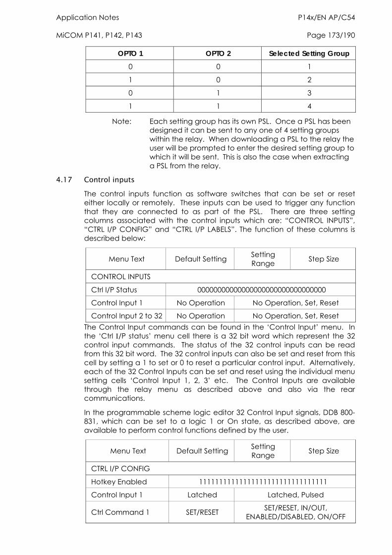
Application Notes P14x/EN AP/C54 MiCOM P141, P142, P143 Page 173/190
OPTO 1 OPTO 2 Selected Setting Group
0 0 1
1 0 2
0 1 3
1 1 4
Note: Each setting group has its own PSL. Once a PSL has been designed it can be sent to any one of 4 setting groups within the relay. When downloading a PSL to the relay the user will be prompted to enter the desired setting group to which it will be sent. This is also the case when extracting a PSL from the relay.
4.17 Control inputs The control inputs function as software switches that can be set or reset either locally or remotely. These inputs can be used to trigger any function that they are connected to as part of the PSL. There are three setting columns associated with the control inputs which are: “CONTROL INPUTS”, “CTRL I/P CONFIG” and “CTRL I/P LABELS”. The function of these columns is described below:
Menu Text Default Setting Setting Range Step Size
CONTROL INPUTS
Ctrl I/P Status 00000000000000000000000000000000
Control Input 1 No Operation No Operation, Set, Reset
Control Input 2 to 32 No Operation No Operation, Set, Reset The Control Input commands can be found in the ‘Control Input’ menu. In the ‘Ctrl /P status’ menu cell there is a 32 bit word which represent the 32 control input commands. The status of the 32 control inputs can be read from this 32 bit word. The 32 control inputs can also be set and reset from this cell by setting a 1 to set or 0 to reset a particular control input. Alternatively, each of the 32 Control Inputs can be set and reset using the individual menu setting cells ‘Control Input 1, 2, 3’ etc. The Control Inputs are available through the relay menu as described above and also via the rear communications.
In the programmable scheme logic editor 32 Control Input signals, DDB 800-831, which can be set to a logic 1 or On state, as described above, are available to perform control functions defined by the user.
Menu Text Default Setting Setting Range Step Size
CTRL I/P CONFIG
Hotkey Enabled 11111111111111111111111111111111
Control Input 1 Latched Latched, Pulsed
Ctrl Command 1 SET/RESET SET/RESET, IN/OUT, ENABLED/DISABLED, ON/OFF
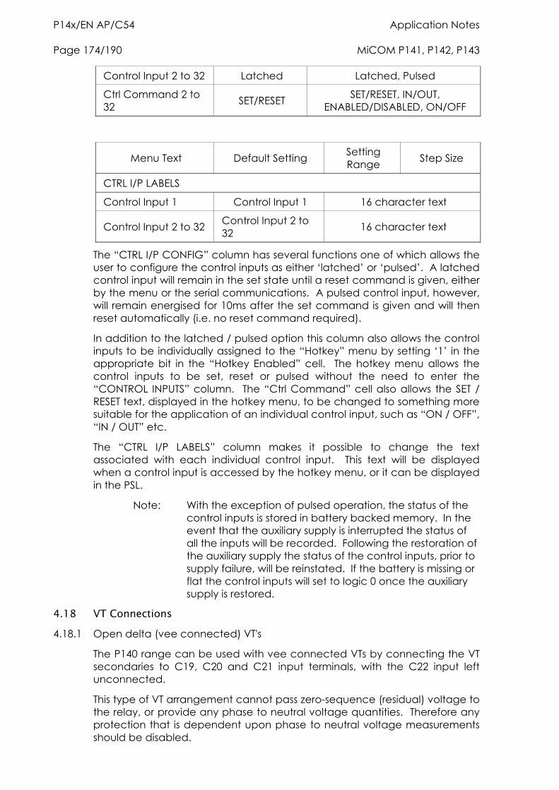
P14x/EN AP/C54 Application Notes Page 174/190 MiCOM P141, P142, P143
Control Input 2 to 32 Latched Latched, Pulsed
Ctrl Command 2 to 32 SET/RESET SET/RESET, IN/OUT,
ENABLED/DISABLED, ON/OFF
Menu Text Default Setting Setting Range Step Size
CTRL I/P LABELS
Control Input 1 Control Input 1 16 character text
Control Input 2 to 32 Control Input 2 to 32 16 character text
The “CTRL I/P CONFIG” column has several functions one of which allows the user to configure the control inputs as either ‘latched’ or ‘pulsed’. A latched control input will remain in the set state until a reset command is given, either by the menu or the serial communications. A pulsed control input, however, will remain energised for 10ms after the set command is given and will then reset automatically (i.e. no reset command required).
In addition to the latched / pulsed option this column also allows the control inputs to be individually assigned to the “Hotkey” menu by setting ‘1’ in the appropriate bit in the “Hotkey Enabled” cell. The hotkey menu allows the control inputs to be set, reset or pulsed without the need to enter the “CONTROL INPUTS” column. The “Ctrl Command” cell also allows the SET / RESET text, displayed in the hotkey menu, to be changed to something more suitable for the application of an individual control input, such as “ON / OFF”, “IN / OUT” etc.
The “CTRL I/P LABELS” column makes it possible to change the text associated with each individual control input. This text will be displayed when a control input is accessed by the hotkey menu, or it can be displayed in the PSL.
Note: With the exception of pulsed operation, the status of the control inputs is stored in battery backed memory. In the event that the auxiliary supply is interrupted the status of all the inputs will be recorded. Following the restoration of the auxiliary supply the status of the control inputs, prior to supply failure, will be reinstated. If the battery is missing or flat the control inputs will set to logic 0 once the auxiliary supply is restored.
4.18 VT Connections 4.18.1 Open delta (vee connected) VT's
The P140 range can be used with vee connected VTs by connecting the VT secondaries to C19, C20 and C21 input terminals, with the C22 input left unconnected.
This type of VT arrangement cannot pass zero-sequence (residual) voltage to the relay, or provide any phase to neutral voltage quantities. Therefore any protection that is dependent upon phase to neutral voltage measurements should be disabled.
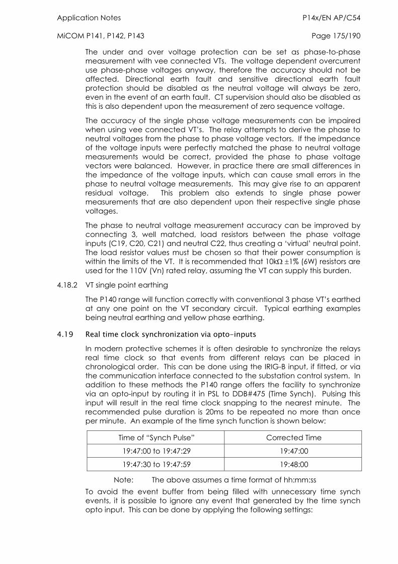
Application Notes P14x/EN AP/C54 MiCOM P141, P142, P143 Page 175/190
The under and over voltage protection can be set as phase-to-phase measurement with vee connected VTs. The voltage dependent overcurrent use phase-phase voltages anyway, therefore the accuracy should not be affected. Directional earth fault and sensitive directional earth fault protection should be disabled as the neutral voltage will always be zero, even in the event of an earth fault. CT supervision should also be disabled as this is also dependent upon the measurement of zero sequence voltage.
The accuracy of the single phase voltage measurements can be impaired when using vee connected VT’s. The relay attempts to derive the phase to neutral voltages from the phase to phase voltage vectors. If the impedance of the voltage inputs were perfectly matched the phase to neutral voltage measurements would be correct, provided the phase to phase voltage vectors were balanced. However, in practice there are small differences in the impedance of the voltage inputs, which can cause small errors in the phase to neutral voltage measurements. This may give rise to an apparent residual voltage. This problem also extends to single phase power measurements that are also dependent upon their respective single phase voltages.
The phase to neutral voltage measurement accuracy can be improved by connecting 3, well matched, load resistors between the phase voltage inputs (C19, C20, C21) and neutral C22, thus creating a ‘virtual’ neutral point. The load resistor values must be chosen so that their power consumption is within the limits of the VT. It is recommended that 10k 1% (6W) resistors are used for the 110V (Vn) rated relay, assuming the VT can supply this burden.
4.18.2 VT single point earthing
The P140 range will function correctly with conventional 3 phase VT’s earthed at any one point on the VT secondary circuit. Typical earthing examples being neutral earthing and yellow phase earthing.
4.19 Real time clock synchronization via opto-inputs In modern protective schemes it is often desirable to synchronize the relays real time clock so that events from different relays can be placed in chronological order. This can be done using the IRIG-B input, if fitted, or via the communication interface connected to the substation control system. In addition to these methods the P140 range offers the facility to synchronize via an opto-input by routing it in PSL to DDB#475 (Time Synch). Pulsing this input will result in the real time clock snapping to the nearest minute. The recommended pulse duration is 20ms to be repeated no more than once per minute. An example of the time synch function is shown below:
Time of “Synch Pulse” Corrected Time
19:47:00 to 19:47:29 19:47:00
19:47:30 to 19:47:59 19:48:00
Note: The above assumes a time format of hh:mm:ss To avoid the event buffer from being filled with unnecessary time synch events, it is possible to ignore any event that generated by the time synch opto input. This can be done by applying the following settings:
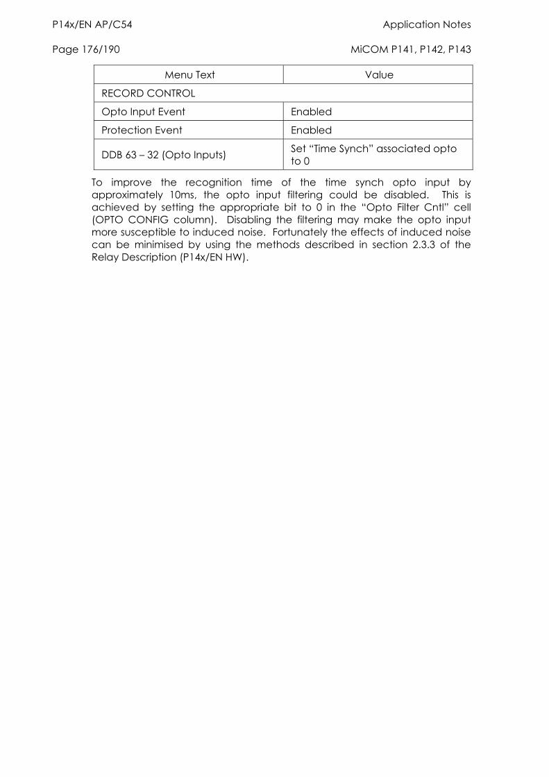
P14x/EN AP/C54 Application Notes Page 176/190 MiCOM P141, P142, P143
Menu Text Value
RECORD CONTROL
Opto Input Event Enabled
Protection Event Enabled
DDB 63 – 32 (Opto Inputs) Set “Time Synch” associated opto to 0
To improve the recognition time of the time synch opto input by approximately 10ms, the opto input filtering could be disabled. This is achieved by setting the appropriate bit to 0 in the “Opto Filter Cntl” cell (OPTO CONFIG column). Disabling the filtering may make the opto input more susceptible to induced noise. Fortunately the effects of induced noise can be minimised by using the methods described in section 2.3.3 of the Relay Description (P14x/EN HW).
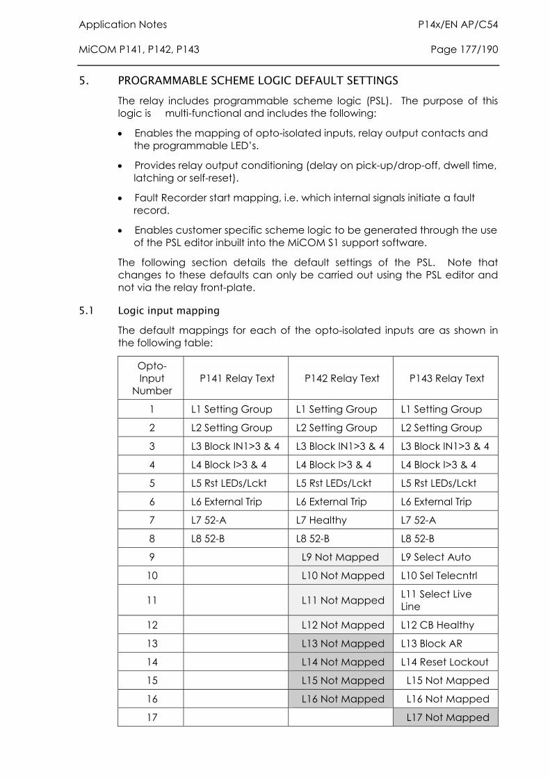
Application Notes P14x/EN AP/C54 MiCOM P141, P142, P143 Page 177/190
5. PROGRAMMABLE SCHEME LOGIC DEFAULT SETTINGS The relay includes programmable scheme logic (PSL). The purpose of this logic is multi-functional and includes the following:
Enables the mapping of opto-isolated inputs, relay output contacts and the programmable LED’s.
Provides relay output conditioning (delay on pick-up/drop-off, dwell time, latching or self-reset).
Fault Recorder start mapping, i.e. which internal signals initiate a fault record.
Enables customer specific scheme logic to be generated through the use of the PSL editor inbuilt into the MiCOM S1 support software.
The following section details the default settings of the PSL. Note that changes to these defaults can only be carried out using the PSL editor and not via the relay front-plate.
5.1 Logic input mapping The default mappings for each of the opto-isolated inputs are as shown in the following table:
Opto-Input
Number P141 Relay Text P142 Relay Text P143 Relay Text
1 L1 Setting Group L1 Setting Group L1 Setting Group
2 L2 Setting Group L2 Setting Group L2 Setting Group
3 L3 Block IN1>3 & 4 L3 Block IN1>3 & 4 L3 Block IN1>3 & 4
4 L4 Block I>3 & 4 L4 Block I>3 & 4 L4 Block I>3 & 4
5 L5 Rst LEDs/Lckt L5 Rst LEDs/Lckt L5 Rst LEDs/Lckt
6 L6 External Trip L6 External Trip L6 External Trip
7 L7 52-A L7 Healthy L7 52-A
8 L8 52-B L8 52-B L8 52-B
9 L9 Not Mapped L9 Select Auto
10 L10 Not Mapped L10 Sel Telecntrl
11 L11 Not Mapped L11 Select Live Line
12 L12 Not Mapped L12 CB Healthy
13 L13 Not Mapped L13 Block AR
14 L14 Not Mapped L14 Reset Lockout
15 L15 Not Mapped L15 Not Mapped
16 L16 Not Mapped L16 Not Mapped
17 L17 Not Mapped
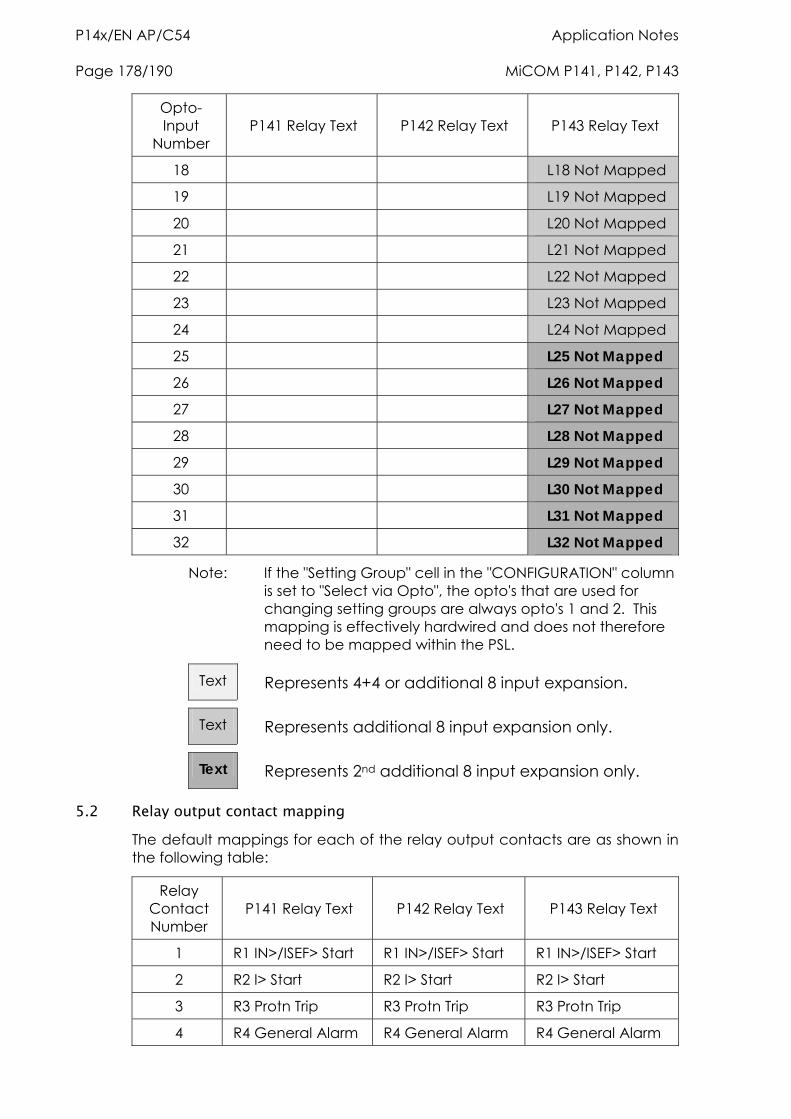
P14x/EN AP/C54 Application Notes Page 178/190 MiCOM P141, P142, P143
Opto-Input
Number P141 Relay Text P142 Relay Text P143 Relay Text
18 L18 Not Mapped
19 L19 Not Mapped
20 L20 Not Mapped
21 L21 Not Mapped
22 L22 Not Mapped
23 L23 Not Mapped
24 L24 Not Mapped
25 L25 Not Mapped
26 L26 Not Mapped
27 L27 Not Mapped
28 L28 Not Mapped
29 L29 Not Mapped
30 L30 Not Mapped
31 L31 Not Mapped
32 L32 Not Mapped
Note: If the "Setting Group" cell in the "CONFIGURATION" column is set to "Select via Opto", the opto's that are used for changing setting groups are always opto's 1 and 2. This mapping is effectively hardwired and does not therefore need to be mapped within the PSL.
Text Represents 4+4 or additional 8 input expansion.
Text Represents additional 8 input expansion only.
Text Represents 2nd additional 8 input expansion only.
5.2 Relay output contact mapping The default mappings for each of the relay output contacts are as shown in the following table:
Relay Contact Number
P141 Relay Text P142 Relay Text P143 Relay Text
1 R1 IN>/ISEF> Start R1 IN>/ISEF> Start R1 IN>/ISEF> Start
2 R2 I> Start R2 I> Start R2 I> Start
3 R3 Protn Trip R3 Protn Trip R3 Protn Trip
4 R4 General Alarm R4 General Alarm R4 General Alarm
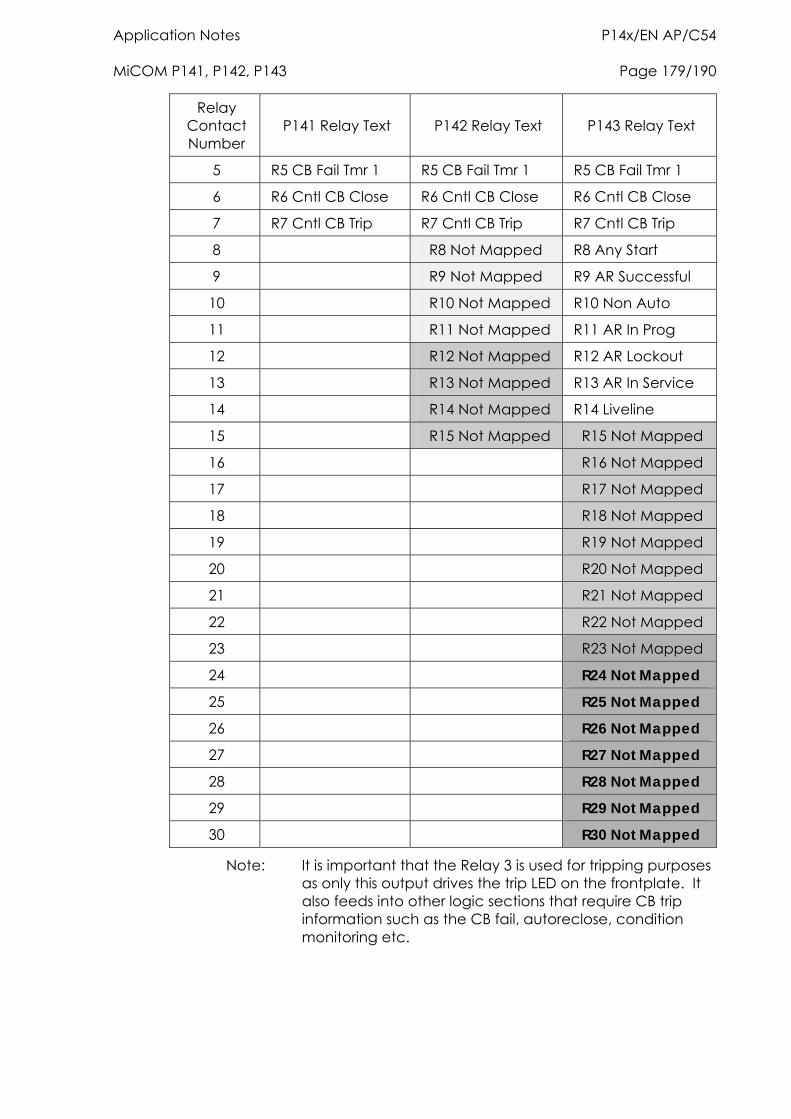
Application Notes P14x/EN AP/C54 MiCOM P141, P142, P143 Page 179/190
Relay Contact Number
P141 Relay Text P142 Relay Text P143 Relay Text
5 R5 CB Fail Tmr 1 R5 CB Fail Tmr 1 R5 CB Fail Tmr 1
6 R6 Cntl CB Close R6 Cntl CB Close R6 Cntl CB Close
7 R7 Cntl CB Trip R7 Cntl CB Trip R7 Cntl CB Trip
8 R8 Not Mapped R8 Any Start
9 R9 Not Mapped R9 AR Successful
10 R10 Not Mapped R10 Non Auto
11 R11 Not Mapped R11 AR In Prog
12 R12 Not Mapped R12 AR Lockout
13 R13 Not Mapped R13 AR In Service
14 R14 Not Mapped R14 Liveline
15 R15 Not Mapped R15 Not Mapped
16 R16 Not Mapped
17 R17 Not Mapped
18 R18 Not Mapped
19 R19 Not Mapped
20 R20 Not Mapped
21 R21 Not Mapped
22 R22 Not Mapped
23 R23 Not Mapped
24 R24 Not Mapped
25 R25 Not Mapped
26 R26 Not Mapped
27 R27 Not Mapped
28 R28 Not Mapped
29 R29 Not Mapped
30 R30 Not Mapped
Note: It is important that the Relay 3 is used for tripping purposes as only this output drives the trip LED on the frontplate. It also feeds into other logic sections that require CB trip information such as the CB fail, autoreclose, condition monitoring etc.
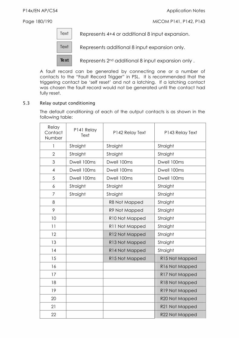
P14x/EN AP/C54 Application Notes Page 180/190 MiCOM P141, P142, P143
Text Represents 4+4 or additional 8 input expansion.
Text Represents additional 8 input expansion only.
Text Represents 2nd additional 8 input expansion only .
A fault record can be generated by connecting one or a number of contacts to the “Fault Record Trigger” in PSL. It is recommended that the triggering contact be ‘self reset’ and not a latching. If a latching contact was chosen the fault record would not be generated until the contact had fully reset.
5.3 Relay output conditioning The default conditioning of each of the output contacts is as shown in the following table:
Relay Contact Number
P141 Relay Text P142 Relay Text P143 Relay Text
1 Straight Straight Straight
2 Straight Straight Straight
3 Dwell 100ms Dwell 100ms Dwell 100ms
4 Dwell 100ms Dwell 100ms Dwell 100ms
5 Dwell 100ms Dwell 100ms Dwell 100ms
6 Straight Straight Straight
7 Straight Straight Straight
8 R8 Not Mapped Straight
9 R9 Not Mapped Straight
10 R10 Not Mapped Straight
11 R11 Not Mapped Straight
12 R12 Not Mapped Straight
13 R13 Not Mapped Straight
14 R14 Not Mapped Straight
15 R15 Not Mapped R15 Not Mapped
16 R16 Not Mapped
17 R17 Not Mapped
18 R18 Not Mapped
19 R19 Not Mapped
20 R20 Not Mapped
21 R21 Not Mapped
22 R22 Not Mapped
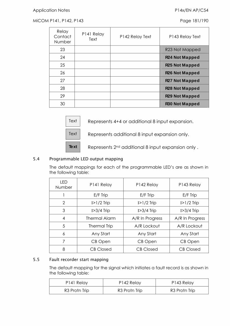
Application Notes P14x/EN AP/C54 MiCOM P141, P142, P143 Page 181/190
Relay Contact Number
P141 Relay Text P142 Relay Text P143 Relay Text
23 R23 Not Mapped
24 R24 Not Mapped
25 R25 Not Mapped
26 R26 Not Mapped
27 R27 Not Mapped
28 R28 Not Mapped
29 R29 Not Mapped
30 R30 Not Mapped
Text Represents 4+4 or additional 8 input expansion.
Text Represents additional 8 input expansion only.
Text Represents 2nd additional 8 input expansion only .
5.4 Programmable LED output mapping The default mappings for each of the programmable LED’s are as shown in the following table:
LED Number P141 Relay P142 Relay P143 Relay
1 E/F Trip E/F Trip E/F Trip
2 >1/2 Trip >1/2 Trip >1/2 Trip
3 >3/4 Trip >3/4 Trip >3/4 Trip
4 Thermal Alarm A/R In Progress A/R In Progress
5 Thermal Trip A/R Lockout A/R Lockout
6 Any Start Any Start Any Start
7 CB Open CB Open CB Open
8 CB Closed CB Closed CB Closed
5.5 Fault recorder start mapping The default mapping for the signal which initiates a fault record is as shown in the following table:
P141 Relay P142 Relay P143 Relay
R3 Protn Trip R3 Protn Trip R3 Protn Trip
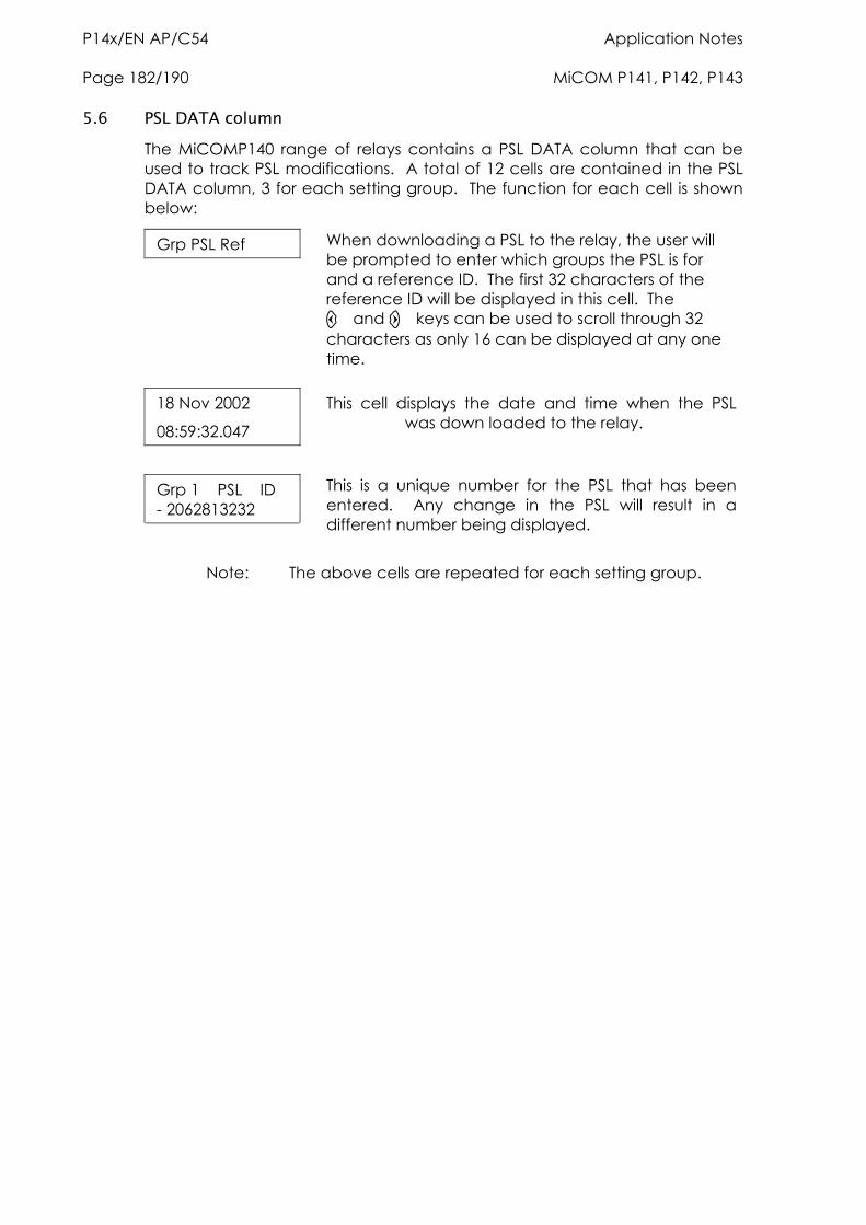
P14x/EN AP/C54 Application Notes Page 182/190 MiCOM P141, P142, P143
5.6 PSL DATA column The MiCOMP140 range of relays contains a PSL DATA column that can be used to track PSL modifications. A total of 12 cells are contained in the PSL DATA column, 3 for each setting group. The function for each cell is shown below:
Grp PSL Ref
When downloading a PSL to the relay, the user will be prompted to enter which groups the PSL is for and a reference ID. The first 32 characters of the reference ID will be displayed in this cell. The and keys can be used to scroll through 32 characters as only 16 can be displayed at any one time.
18 Nov 2002
08:59:32.047
This cell displays the date and time when the PSL was down loaded to the relay.
Grp 1 PSL ID - 2062813232
This is a unique number for the PSL that has been entered. Any change in the PSL will result in a different number being displayed.
Note: The above cells are repeated for each setting group.
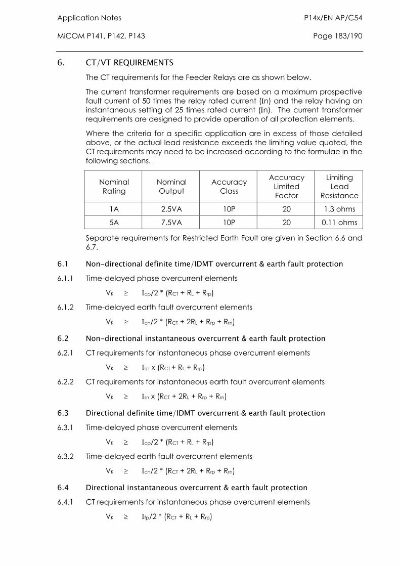
Application Notes P14x/EN AP/C54 MiCOM P141, P142, P143 Page 183/190
6. CT/VT REQUIREMENTS The CT requirements for the Feeder Relays are as shown below.
The current transformer requirements are based on a maximum prospective fault current of 50 times the relay rated current (n) and the relay having an instantaneous setting of 25 times rated current (n). The current transformer requirements are designed to provide operation of all protection elements.
Where the criteria for a specific application are in excess of those detailed above, or the actual lead resistance exceeds the limiting value quoted, the CT requirements may need to be increased according to the formulae in the following sections.
Nominal Rating
Nominal Output
Accuracy Class
Accuracy Limited Factor
Limiting Lead
Resistance
1A 2.5VA 10P 20 1.3 ohms
5A 7.5VA 10P 20 0.11 ohms
Separate requirements for Restricted Earth Fault are given in Section 6.6 and 6.7.
6.1 Non-directional definite time/IDMT overcurrent & earth fault protection 6.1.1 Time-delayed phase overcurrent elements
VK cp/2 * (RCT + RL + Rrp)
6.1.2 Time-delayed earth fault overcurrent elements
VK cn/2 * (RCT + 2RL + Rrp + Rrn)
6.2 Non-directional instantaneous overcurrent & earth fault protection 6.2.1 CT requirements for instantaneous phase overcurrent elements
VK sp x (RCT + RL + Rrp)
6.2.2 CT requirements for instantaneous earth fault overcurrent elements
VK sn x (RCT + 2RL + Rrp + Rrn)
6.3 Directional definite time/IDMT overcurrent & earth fault protection 6.3.1 Time-delayed phase overcurrent elements
VK cp/2 * (RCT + RL + Rrp)
6.3.2 Time-delayed earth fault overcurrent elements
VK cn/2 * (RCT + 2RL + Rrp + Rrn)
6.4 Directional instantaneous overcurrent & earth fault protection 6.4.1 CT requirements for instantaneous phase overcurrent elements
VK fp/2 * (RCT + RL + Rrp)
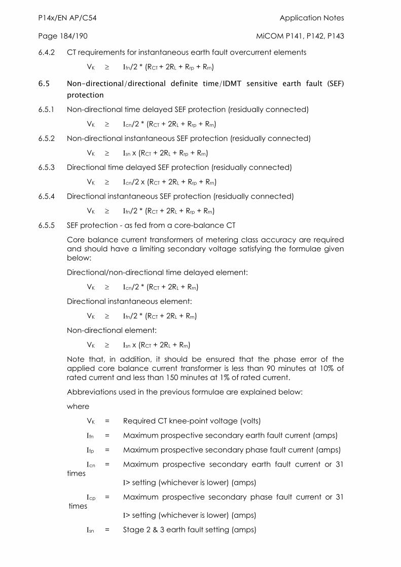
P14x/EN AP/C54 Application Notes Page 184/190 MiCOM P141, P142, P143
6.4.2 CT requirements for instantaneous earth fault overcurrent elements
VK fn/2 * (RCT + 2RL + Rrp + Rrn)
6.5 Non-directional/directional definite time/IDMT sensitive earth fault (SEF) protection
6.5.1 Non-directional time delayed SEF protection (residually connected)
VK cn/2 * (RCT + 2RL + Rrp + Rrn)
6.5.2 Non-directional instantaneous SEF protection (residually connected)
VK sn x (RCT + 2RL + Rrp + Rrn)
6.5.3 Directional time delayed SEF protection (residually connected)
VK cn/2 x (RCT + 2RL + Rrp + Rrn)
6.5.4 Directional instantaneous SEF protection (residually connected)
VK fn/2 * (RCT + 2RL + Rrp + Rrn)
6.5.5 SEF protection - as fed from a core-balance CT
Core balance current transformers of metering class accuracy are required and should have a limiting secondary voltage satisfying the formulae given below:
Directional/non-directional time delayed element:
VK cn/2 * (RCT + 2RL + Rrn)
Directional instantaneous element:
VK fn/2 * (RCT + 2RL + Rrn)
Non-directional element:
VK sn x (RCT + 2RL + Rrn)
Note that, in addition, it should be ensured that the phase error of the applied core balance current transformer is less than 90 minutes at 10% of rated current and less than 150 minutes at 1% of rated current.
Abbreviations used in the previous formulae are explained below:
where
VK = Required CT knee-point voltage (volts)
fn = Maximum prospective secondary earth fault current (amps)
fp = Maximum prospective secondary phase fault current (amps)
cn = Maximum prospective secondary earth fault current or 31 times > setting (whichever is lower) (amps)
cp = Maximum prospective secondary phase fault current or 31 times > setting (whichever is lower) (amps)
sn = Stage 2 & 3 earth fault setting (amps)
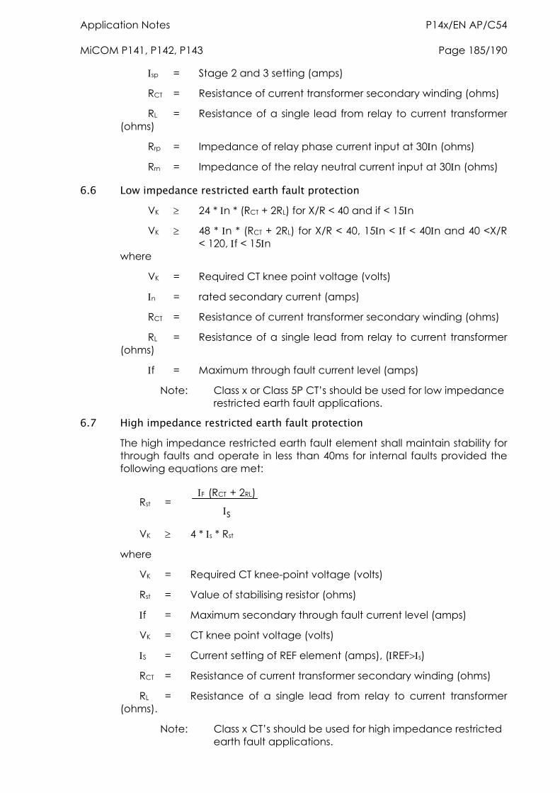
Application Notes P14x/EN AP/C54 MiCOM P141, P142, P143 Page 185/190
sp = Stage 2 and 3 setting (amps)
RCT = Resistance of current transformer secondary winding (ohms)
RL = Resistance of a single lead from relay to current transformer (ohms)
Rrp = Impedance of relay phase current input at 30n (ohms)
Rrn = Impedance of the relay neutral current input at 30n (ohms)
6.6 Low impedance restricted earth fault protection VK 24 * n * (RCT + 2RL) for X/R < 40 and if < 15n
VK 48 * n * (RCT + 2RL) for X/R < 40, 15n < f < 40n and 40 <X/R < 120, f < 15n where
VK = Required CT knee point voltage (volts)
n = rated secondary current (amps)
RCT = Resistance of current transformer secondary winding (ohms)
RL = Resistance of a single lead from relay to current transformer (ohms)
f = Maximum through fault current level (amps)
Note: Class x or Class 5P CT’s should be used for low impedance restricted earth fault applications.
6.7 High impedance restricted earth fault protection The high impedance restricted earth fault element shall maintain stability for through faults and operate in less than 40ms for internal faults provided the following equations are met:
Rst = F (RCT + 2RL)
s
VK 4 * s * Rst
where
VK = Required CT knee-point voltage (volts)
Rst = Value of stabilising resistor (ohms)
f = Maximum secondary through fault current level (amps)
VK = CT knee point voltage (volts)
S = Current setting of REF element (amps), (REFs)
RCT = Resistance of current transformer secondary winding (ohms)
RL = Resistance of a single lead from relay to current transformer (ohms).
Note: Class x CT’s should be used for high impedance restricted earth fault applications.
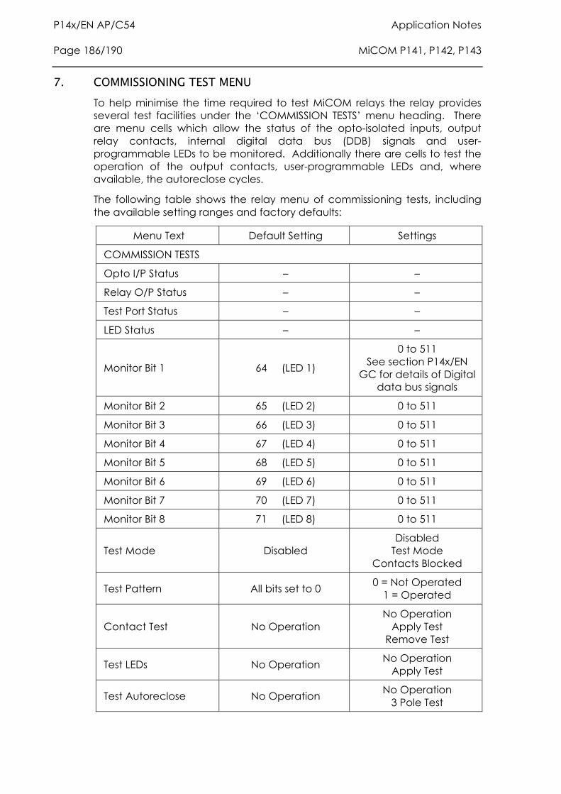
P14x/EN AP/C54 Application Notes Page 186/190 MiCOM P141, P142, P143
7. COMMISSIONING TEST MENU To help minimise the time required to test MiCOM relays the relay provides several test facilities under the ‘COMMISSION TESTS’ menu heading. There are menu cells which allow the status of the opto-isolated inputs, output relay contacts, internal digital data bus (DDB) signals and user-programmable LEDs to be monitored. Additionally there are cells to test the operation of the output contacts, user-programmable LEDs and, where available, the autoreclose cycles.
The following table shows the relay menu of commissioning tests, including the available setting ranges and factory defaults:
Menu Text Default Setting Settings
COMMISSION TESTS
Opto I/P Status – –
Relay O/P Status – –
Test Port Status – –
LED Status – –
Monitor Bit 1 64 (LED 1)
0 to 511 See section P14x/EN
GC for details of Digital data bus signals
Monitor Bit 2 65 (LED 2) 0 to 511
Monitor Bit 3 66 (LED 3) 0 to 511
Monitor Bit 4 67 (LED 4) 0 to 511
Monitor Bit 5 68 (LED 5) 0 to 511
Monitor Bit 6 69 (LED 6) 0 to 511
Monitor Bit 7 70 (LED 7) 0 to 511
Monitor Bit 8 71 (LED 8) 0 to 511
Test Mode Disabled Disabled
Test Mode Contacts Blocked
Test Pattern All bits set to 0 0 = Not Operated 1 = Operated
Contact Test No Operation No Operation
Apply Test Remove Test
Test LEDs No Operation No Operation Apply Test
Test Autoreclose No Operation No Operation 3 Pole Test

Application Notes P14x/EN AP/C54 MiCOM P141, P142, P143 Page 187/190
7.1 Opto I/P status This menu cell displays the status of the relay’s opto-isolated inputs as a binary string, a ‘1’ indicating an energised opto-isolated input and a ‘0’ a de-energised one. If the cursor is moved along the binary numbers the corresponding label text will be displayed for each logic input.
It can be used during commissioning or routine testing to monitor the status of the opto-isolated inputs whilst they are sequentially energised with a suitable dc voltage.
7.2 Relay O/P status This menu cell displays the status of the digital data bus (DDB) signals that result in energisation of the output relays as a binary string, a ‘1’ indicating an operated state and ‘0’ a non-operated state. If the cursor is moved along the binary numbers the corresponding label text will be displayed for each relay output.
The information displayed can be used during commissioning or routine testing to indicate the status of the output relays when the relay is ‘in service’. Additionally fault finding for output relay damage can be performed by comparing the status of the output contact under investigation with it’s associated bit.
Note: When the ‘Test Mode’ cell is set to ‘Enabled’ this cell will continue to indicate which contacts would operate if the relay was in-service, it does not show the actual status of the output relays.
7.3 Test port status This menu cell displays the status of the eight digital data bus (DDB) signals that have been allocated in the ‘Monitor Bit’ cells. If the cursor is moved along the binary numbers the corresponding DDB signal text string will be displayed for each monitor bit.
By using this cell with suitable monitor bit settings, the state of the DDB signals can be displayed as various operating conditions or sequences are applied to the relay. Thus the programmable scheme logic can be tested.
As an alternative to using this cell, the optional monitor/download port test box can be plugged into the monitor/download port located behind the bottom access cover. Details of the monitor/download port test box can be found in section 7.11 of these Application Notes (P14x/EN AP).
7.4 LED status The ‘LED Status’ cell is an eight bit binary string that indicates which of the user-programmable LEDs on the relay are illuminated when accessing the relay from a remote location, a ‘1’ indicating a particular LED is lit and a ‘0’ not lit.
7.5 Monitor bits 1 to 8 The eight ‘Monitor Bit’ cells allow the user to select the status of which digital data bus signals can be observed in the ‘Test Port Status’ cell or via the monitor/download port.
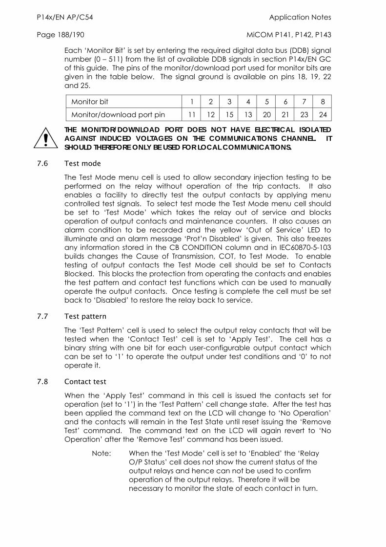
P14x/EN AP/C54 Application Notes Page 188/190 MiCOM P141, P142, P143
Each ‘Monitor Bit’ is set by entering the required digital data bus (DDB) signal number (0 – 511) from the list of available DDB signals in section P14x/EN GC of this guide. The pins of the monitor/download port used for monitor bits are given in the table below. The signal ground is available on pins 18, 19, 22 and 25.
Monitor bit 1 2 3 4 5 6 7 8
Monitor/download port pin 11 12 15 13 20 21 23 24
THE MONITOR/DOWNLOAD PORT DOES NOT HAVE ELECTRICAL ISOLATED AGAINST INDUCED VOLTAGES ON THE COMMUNICATIONS CHANNEL. IT SHOULD THEREFORE ONLY BE USED FOR LOCAL COMMUNICATIONS.
7.6 Test mode The Test Mode menu cell is used to allow secondary injection testing to be performed on the relay without operation of the trip contacts. It also enables a facility to directly test the output contacts by applying menu controlled test signals. To select test mode the Test Mode menu cell should be set to ‘Test Mode’ which takes the relay out of service and blocks operation of output contacts and maintenance counters. It also causes an alarm condition to be recorded and the yellow ‘Out of Service’ LED to illuminate and an alarm message ‘Prot’n Disabled’ is given. This also freezes any information stored in the CB CONDITION column and in IEC60870-5-103 builds changes the Cause of Transmission, COT, to Test Mode. To enable testing of output contacts the Test Mode cell should be set to Contacts Blocked. This blocks the protection from operating the contacts and enables the test pattern and contact test functions which can be used to manually operate the output contacts. Once testing is complete the cell must be set back to ‘Disabled’ to restore the relay back to service.
7.7 Test pattern The ‘Test Pattern’ cell is used to select the output relay contacts that will be tested when the ‘Contact Test’ cell is set to ‘Apply Test’. The cell has a binary string with one bit for each user-configurable output contact which can be set to ‘1’ to operate the output under test conditions and ‘0’ to not operate it.
7.8 Contact test When the ‘Apply Test’ command in this cell is issued the contacts set for operation (set to ‘1’) in the ‘Test Pattern’ cell change state. After the test has been applied the command text on the LCD will change to ‘No Operation’ and the contacts will remain in the Test State until reset issuing the ‘Remove Test’ command. The command text on the LCD will again revert to ‘No Operation’ after the ‘Remove Test’ command has been issued.
Note: When the ‘Test Mode’ cell is set to ‘Enabled’ the ‘Relay O/P Status’ cell does not show the current status of the output relays and hence can not be used to confirm operation of the output relays. Therefore it will be necessary to monitor the state of each contact in turn.
Application Notes P14x/EN AP/C54 MiCOM P141, P142, P143 Page 189/190
7.9 Test LEDs When the ‘Apply Test’ command in this cell is issued the eight user-programmable LED’s will illuminate for approximately 2 seconds before they extinguish and the command text on the LCD reverts to ‘No Operation’.
7.10 Test autoreclose Where the relay provides an autoreclose function, this cell will be available for testing the sequence of circuit breaker trip and autoreclose cycles with the settings applied.
Issuing the command ‘3 Pole Trip’ will cause the relay to perform the first three phase trip/reclose cycle so that associated output contacts can be checked for operation at the correct times during the cycle. Once the trip output has operated the command text will revert to ‘No Operation’ whilst the rest of the autoreclose cycle is performed. To test subsequent three phase autoreclose cycles repeat the ‘3 Pole Trip’ command.
Note: The factory settings for the relay’s programmable scheme logic has the ‘AR Trip Test’ signal mapped to relay 3. If the programmable scheme logic has been changed, it is essential that this signal remains mapped to relay 3 for the ‘Test Autoreclose’ facility to work.
7.11 Using a monitor/download port test box A monitor/download port test box containing 8 LED’s and a switchable audible indicator is available from ALSTOM Grid, or one of their regional sales offices. It is housed in a small plastic box with a 25-pin male D-connector that plugs directly into the relay’s monitor/download port. There is also a 25-pin female D-connector which allows other connections to be made to the monitor/download port whilst the monitor/download port test box is in place.
Each LED corresponds to one of the monitor bit pins on the monitor/download port with ‘Monitor Bit 1’ being on the left hand side when viewing from the front of the relay. The audible indicator can either be selected to sound if a voltage appears on any of the eight monitor pins or remain silent so that indication of state is by LED alone.

P14x/EN AP/C54 Application Notes Page 190/190 MiCOM P141, P142, P143

Relay Description P14x/EN HW/C54 MiCOM P141, P142, P143
RELAY DESCRIPTION

P14x/EN HW/C54 Relay Description MiCOM P141, P142, P143
Relay Description P14x/EN HW/C54 MiCOM P141, P142, P143 Page 1/22
CONTENT
1. RELAY SYSTEM OVERVIEW 3
1.1 Hardware overview 3 1.1.1 Processor board 3
1.1.2 Input module 3
1.1.3 Power supply module 3
1.1.4 IRIG-B board 3
1.1.5 Second rear comms board 3
1.1.6 Ethernet board 3
1.2 Software overview 4 1.2.1 Real-time operating system 4
1.2.2 System services software 5
1.2.3 Platform software 5
1.2.4 Protection & control software 6
1.2.5 Disturbance recorder 6
2. HARDWARE MODULES 7
2.1 Processor board 7
2.2 Internal communication buses 7
2.3 Input module 7 2.3.1 Transformer board 8
2.3.2 Input board 8
2.3.3 Universal opto isolated logic inputs 9
2.4 Power supply module (including output relays) 10 2.4.1 Power supply board (including EIA(RS)485 communication interface) 10
2.4.2 Output relay board 11
2.5 IRIG-B board 11
2.6 Second rear communications board 12
2.7 Ethernet board 12
2.8 Mechanical layout 13
P14x/EN HW/C54 Relay Description Page 2/22 MiCOM P141, P142, P143
3. RELAY SOFTWARE 14
3.1 Real-time operating system 14
3.2 System services software 14
3.3 Platform software 15 3.3.1 Record logging 15
3.3.2 Settings database 15
3.3.3 Database interface 15
3.4 Protection and control software 16 3.4.1 Overview - protection and control scheduling 16
3.4.2 Signal processing 16
3.4.3 Programmable scheme logic 17
3.4.4 Event and fault recording 17
3.4.5 Disturbance recorder 18
3.4.6 Fault locator 18
4. SELF TESTING & DIAGNOSTICS 19
4.1 Start-up self-testing 19 4.1.1 System boot 19
4.1.2 Initialisation software 19
4.1.3 Platform software initialisation & monitoring 20
4.2 Continuous self-testing 20
Figure 1: Relay modules and information flow 5
Figure 2: Main input board 8
Figure 3: Rear comms port 12
Figure 4: Relay software structure 14
Relay Description P14x/EN HW/C54 MiCOM P141, P142, P143 Page 3/22
1. RELAY SYSTEM OVERVIEW
1.1 Hardware overview The relay hardware is based on a modular design whereby the relay is made up of an assemblage of several modules which are drawn from a standard range. Some modules are essential while others are optional depending on the user’s requirements.
The different modules that can be present in the relay are as follows:
1.1.1 Processor board
The processor board performs all calculations for the relay and controls the operation of all other modules within the relay. The processor board also contains and controls the user interfaces (LCD, LEDs, keypad and communication interfaces).
1.1.2 Input module
The input module converts the information contained in the analog and digital input signals into a format suitable for processing by the processor board. The standard input module consists of two boards: a transformer board to provide electrical isolation and a main input board which provides analog to digital conversion and the isolated digital inputs.
1.1.3 Power supply module
The power supply module provides a power supply to all of the other modules in the relay, at three different voltage levels. The power supply board also provides the EIA(RS)485 electrical connection for the rear communication port. On a second board the power supply module contains the relays which provide the output contacts.
The power supply module also provides a 48V external field supply to drive the opto isolated digital inputs.
1.1.4 IRIG-B board
This board, which is optional, can be used where an IRIG-B signal is available to provide an accurate time reference for the relay. There is also an option on this board to specify a fibre optic rear communication port, for use with IEC 60870 communication only.
1.1.5 Second rear comms board
The optional second rear port is designed typically for dial-up modem access by protection engineers/operators, when the main port is reserved for SCADA traffic. Communication is via one of three physical links: K-Bus, EIA(RS)485 or EIA(RS)232. The port supports full local or remote protection and control access by MiCOM S1 software. The second rear port is also available with an on board IRIG-B input.
1.1.6 Ethernet board
This is a mandatory board for UCA2.0 enabled relays. It provides network connectivity through either copper or fibre media at rates of 10Mb/s or 100Mb/s. This board, the IRIG-B board and second rear comms board are mutually exclusive as they both utilise slot A within the relay case.
P14x/EN HW/C54 Relay Description Page 4/22 MiCOM P141, P142, P143
All modules are connected by a parallel data and address bus which allows the processor board to send and receive information to and from the other modules as required. There is also a separate serial data bus for conveying sample data from the input module to the processor. Figure 1 shows the modules of the relay and the flow of information between them.
1.2 Software overview The software for the relay can be conceptually split into four elements: the real-time operating system, the system services software, the platform software and the protection and control software. These four elements are not distinguishable to the user, and are all processed by the same processor board. The distinction between the four parts of the software is made purely for the purpose of explanation here:
1.2.1 Real-time operating system
The real time operating system is used to provide a framework for the different parts of the relay’s software to operate within. To this end the software is split into tasks.
The real-time operating system is responsible for scheduling the processing of these tasks such that they are carried out in the time available and in the desired order of
Priority. The operating system is also responsible for the exchange of information between tasks, in the form of messages.
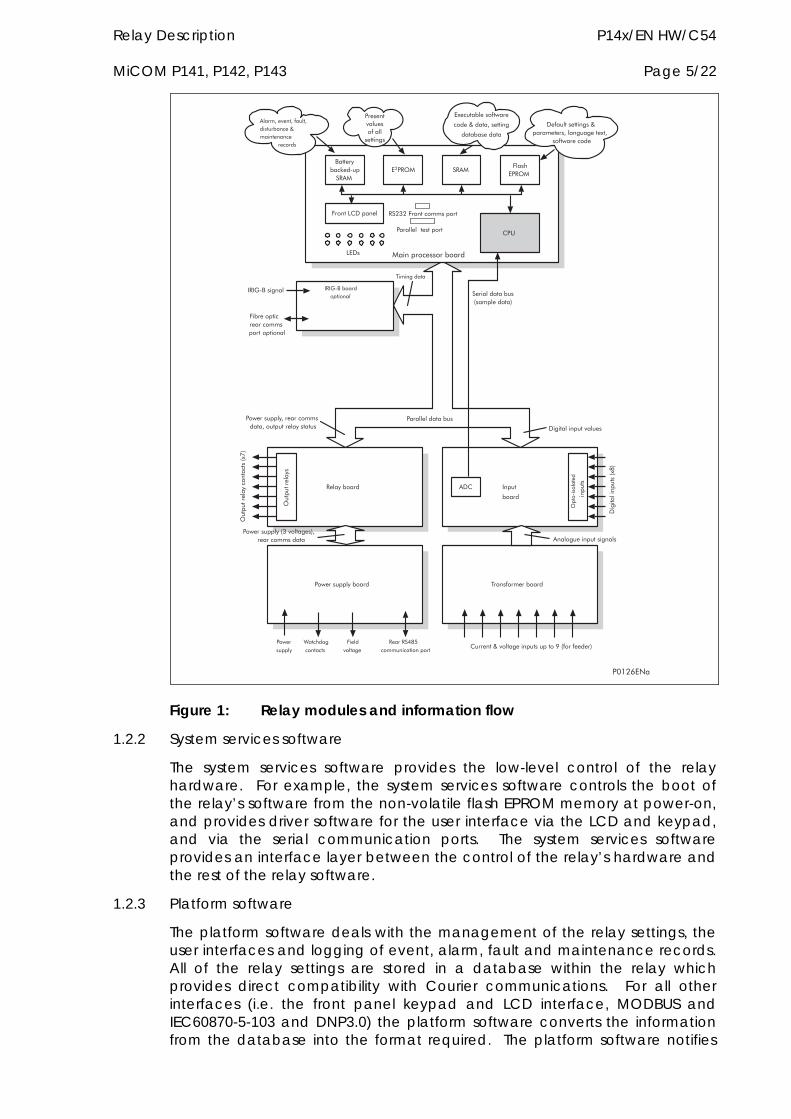
Relay Description P14x/EN HW/C54 MiCOM P141, P142, P143 Page 5/22
������������ ���
������ ���
������������ ��� ����������� ���
�����
���
�������������� ��
������� �����������
� �� � ����!���"��� �
#�$
!����%#&������ ��'('�!�����������
������������������
%�&�
#�������)�*���+��������������,�-���������.
&�+������������-/0.
����������
�������102�������������
������������������-/3.
�&#
�������*����������������+�
�/���� ����������
���)�����4�������+
���� ��������
&�������������+��)����������4����+��+����/�4
����������
���5��� �����������
���5�����+���
!� ����������������� ��������
�����4��*���4������4������ ����)��������������������������
������������
����������
������
����+�����������+����������������-(�*���+��.4
�������������
&�+�����������*�����
�����������4�������������4�������������������
�����+�����
6��"�+�����
!����*���+�
������������ ��-�����������.
'
�78'9�:�
Figure 1: Relay modules and information flow
1.2.2 System services software
The system services software provides the low-level control of the relay hardware. For example, the system services software controls the boot of the relay’s software from the non-volatile flash EPROM memory at power-on, and provides driver software for the user interface via the LCD and keypad, and via the serial communication ports. The system services software provides an interface layer between the control of the relay’s hardware and the rest of the relay software.
1.2.3 Platform software
The platform software deals with the management of the relay settings, the user interfaces and logging of event, alarm, fault and maintenance records. All of the relay settings are stored in a database within the relay which provides direct compatibility with Courier communications. For all other interfaces (i.e. the front panel keypad and LCD interface, MODBUS and IEC60870-5-103 and DNP3.0) the platform software converts the information from the database into the format required. The platform software notifies
P14x/EN HW/C54 Relay Description Page 6/22 MiCOM P141, P142, P143
the protection & control software of all settings changes and logs data as specified by the protection & control software.
1.2.4 Protection & control software
The protection and control software performs the calculations for all of the protection algorithms of the relay. This includes digital signal processing such as Fourier filtering and ancillary tasks such as the measurements. The protection & control software interfaces with the platform software for settings changes and logging of records, and with the system services software for acquisition of sample data and access to output relays and digital opto-isolated inputs.
1.2.5 Disturbance recorder
The analogue values and logic signals are routed from the protection and control software to the disturbance recorder software. The platform software interfaces to the disturbance recorder to allow extraction of the stored records.
Relay Description P14x/EN HW/C54 MiCOM P141, P142, P143 Page 7/22
2. HARDWARE MODULES The relay is based on a modular hardware design where each module performs a separate function within the relay operation. This section describes the functional operation of the various hardware modules.
2.1 Processor board The relay is based around a TMS320VC33 floating point, 32-bit digital signal processor (DSP) operating at a clock frequency of 75MHz. This processor performs all of the calculations for the relay, including the protection functions, control of the data communication and user interfaces including the operation of the LCD, keypad and LEDs.
The processor board is located directly behind the relay’s front panel which allows the LCD and LEDs to be mounted on the processor board along with the front panel communication ports. These comprise the 9-pin D-connector for EIA(RS)232 serial communications (e.g. using MiCOM S1 and Courier communications) and the 25-pin D-connector relay test port for parallel communication. All serial communication is handled using a field programmable gate array (FPGA).
The memory provided on the main processor board is split into two categories, volatile and non-volatile: the volatile memory is fast access SRAM which is used for the storage and execution of the processor software, and data storage as required during the processor’s calculations. The non-volatile memory is sub-divided into 2 groups: 4MB of flash memory for non-volatile storage of software code, text and configuration data including the present setting values, and 2MB of battery backed-up SRAM for the storage of disturbance, event, fault and maintenance record data.
2.2 Internal communication buses The relay has two internal buses for the communication of data between different modules. The main bus is a parallel link which is part of a 64-way ribbon cable. The ribbon cable carries the data and address bus signals in addition to control signals and all power supply lines. Operation of the bus is driven by the main processor board which operates as a master while all other modules within the relay are slaves.
The second bus is a serial link which is used exclusively for communicating the digital sample values from the input module to the main processor board. The DSP processor has a built-in serial port which is used to read the sample data from the serial bus. The serial bus is also carried on the 64-way ribbon cable.
2.3 Input module The input module provides the interface between the relay processor board and the analog and digital signals coming into the relay. The input module consists of two PCBs; the main input board and a transformer board. The P141 and P142 relays provide three voltage inputs and four current inputs. The P143 relay provides an additional voltage input for the check sync function.
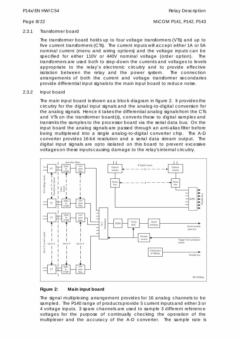
P14x/EN HW/C54 Relay Description Page 8/22 MiCOM P141, P142, P143
2.3.1 Transformer board
The transformer board holds up to four voltage transformers (VTs) and up to five current transformers (CTs). The current inputs will accept either 1A or 5A nominal current (menu and wiring options) and the voltage inputs can be specified for either 110V or 440V nominal voltage (order option). The transformers are used both to step-down the currents and voltages to levels appropriate to the relay’s electronic circuitry and to provide effective isolation between the relay and the power system. The connection arrangements of both the current and voltage transformer secondaries provide differential input signals to the main input board to reduce noise.
2.3.2 Input board
The main input board is shown as a block diagram in figure 2. It provides the circuitry for the digital input signals and the analog-to-digital conversion for the analog signals. Hence it takes the differential analog signals from the CTs and VTs on the transformer board(s), converts these to digital samples and transmits the samples to the processor board via the serial data bus. On the input board the analog signals are passed through an anti-alias filter before being multiplexed into a single analog-to-digital converter chip. The A-D converter provides 16-bit resolution and a serial data stream output. The digital input signals are opto isolated on this board to prevent excessive voltages on these inputs causing damage to the relay's internal circuitry.
;�
#�
;�
#�
������89� ���&#
�����������
�����������
:���������
:���������
������
��������������
����������
89<8
��������/��
������������������
����������� ���
�����
���
01 11
$����2��������������
(=1�*���+��������
0���+�����������
��������� ��
������������������ ��
���++������������� ���
#��� ������ �� �
��������� ��
$����2$����2 $����2
&��������+��
&��������+��
&��������+��
&��������+��
%�����������
%�����������
%�����������
%�����������
0
'
�78'3�:�
Figure 2: Main input board
The signal multiplexing arrangement provides for 16 analog channels to be sampled. The P140 range of products provide 5 current inputs and either 3 or 4 voltage inputs. 3 spare channels are used to sample 3 different reference voltages for the purpose of continually checking the operation of the multiplexer and the accuracy of the A-D converter. The sample rate is
Relay Description P14x/EN HW/C54 MiCOM P141, P142, P143 Page 9/22
maintained at 24 samples per cycle of the power waveform by a logic control circuit which is driven by the frequency tracking function on the main processor board. The calibration E2PROM holds the calibration coefficients which are used by the processor board to correct for any amplitude or phase errors introduced by the transformers and analog circuitry.
The other function of the input board is to read the state of the signals present on the digital inputs and present this to the parallel data bus for processing. The input board holds 8 optical isolators for the connection of up to eight digital input signals. The opto-isolators are used with the digital signals for the same reason as the transformers with the analog signals; to isolate the relay’s electronics from the power system environment. A 48V ‘field voltage’ supply is provided at the back of the relay for use in driving the digital opto-inputs. The input board provides some hardware filtering of the digital signals to remove unwanted noise before buffering the signals for reading on the parallel data bus. Depending on the relay model, more than 8 digital input signals can be accepted by the relay. This is achieved by the use of an additional opto-board which contains the same provision for 8 isolated digital inputs as the main input board, but does not contain any of the circuits for analog signals which are provided on the main input board.
For the P140 feeder protection relay, the protection task is executed twice per cycle, i.e. after every 12 samples for the sample rate of 24 samples per power cycle used by the relay. Therefore, the time taken to register a change in the state of an opto input can vary between a half to one cycle. The time to register the change of state will depend on if the opto input changes state at the start or end of a protection task cycle with the additional half cycle filtering time.
2.3.3 Universal opto isolated logic inputs
The P140 series relays are fitted with universal opto isolated logic inputs that can be programmed for the nominal battery voltage of the circuit of which they are a part. They nominally provide a Logic 1 or On value for Voltages 80% of the set lower nominal voltage and a Logic 0 or Off value for the voltages 60% of the set higher nominal voltage. This lower value eliminates fleeting pickups that may occur during a battery earth fault, when stray capacitance may present up to 50% of battery voltage across an input. Each input also has a selectable filter of ½ cycle which renders the input immune to induced noise on the wiring: although this method is secure it can be slow, particularly for intertripping and back-tripping. This can be improved by switching off the ½ cycle filter in which case one of the following methods to reduce ac noise should be considered. The first method is to use double pole switching on the input, the second is to use screened twisted cable on the input circuit.
In the Opto Config menu the nominal battery voltage can be selected for all opto inputs by selecting one of the five standard ratings in the Global Nominal V settings. If Custom is selected then each opto input can individually be set to a nominal voltage value.
The P142 can have an optional expansion card that will increase the number of opto inputs to 16. The P143 can have up to 2 expansion cards that will increase the number of opto inputs to 32.
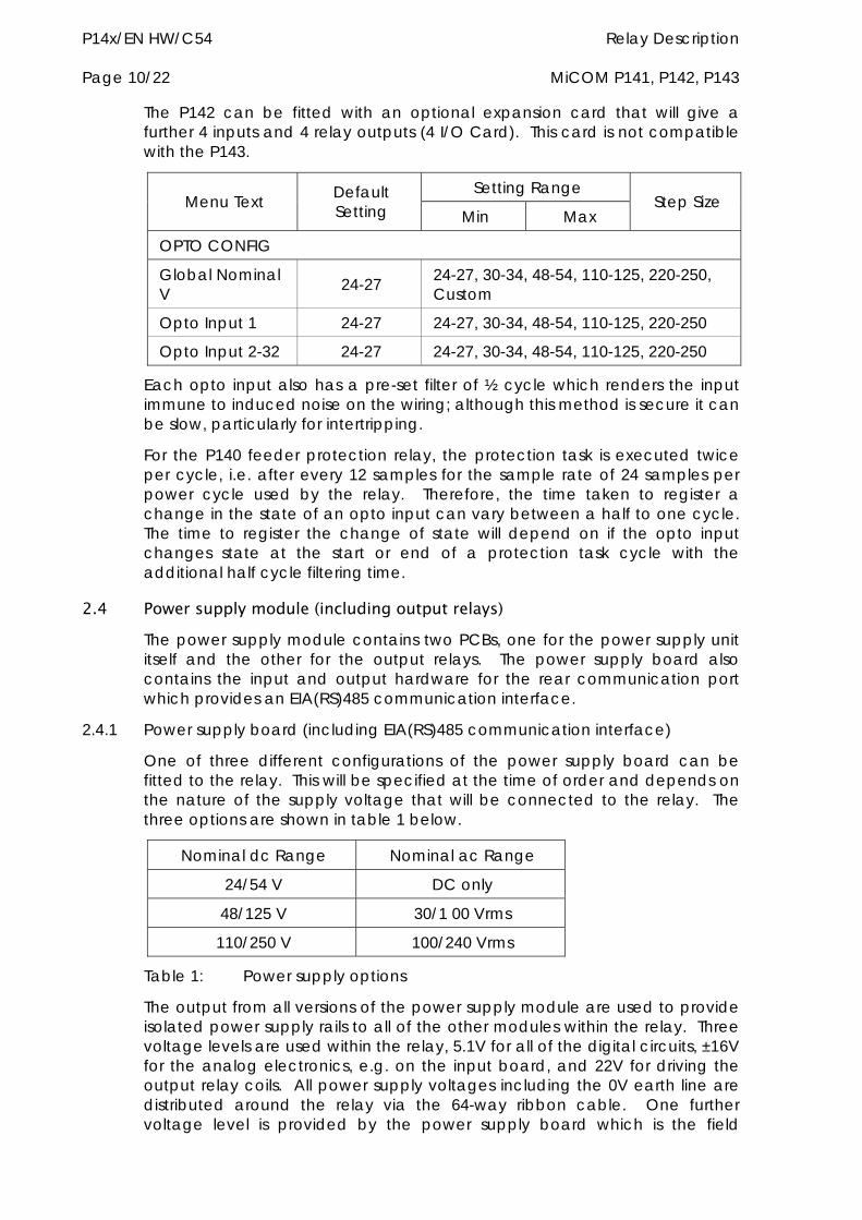
P14x/EN HW/C54 Relay Description Page 10/22 MiCOM P141, P142, P143
The P142 can be fitted with an optional expansion card that will give a further 4 inputs and 4 relay outputs (4 I/O Card). This card is not compatible with the P143.
Setting Range Menu Text Default
Setting Min Max Step Size
OPTO CONFIG
Global Nominal V 24-27 24-27, 30-34, 48-54, 110-125, 220-250,
Custom
Opto Input 1 24-27 24-27, 30-34, 48-54, 110-125, 220-250
Opto Input 2-32 24-27 24-27, 30-34, 48-54, 110-125, 220-250
Each opto input also has a pre-set filter of ½ cycle which renders the input immune to induced noise on the wiring; although this method is secure it can be slow, particularly for intertripping.
For the P140 feeder protection relay, the protection task is executed twice per cycle, i.e. after every 12 samples for the sample rate of 24 samples per power cycle used by the relay. Therefore, the time taken to register a change in the state of an opto input can vary between a half to one cycle. The time to register the change of state will depend on if the opto input changes state at the start or end of a protection task cycle with the additional half cycle filtering time.
2.4 Power supply module (including output relays) The power supply module contains two PCBs, one for the power supply unit itself and the other for the output relays. The power supply board also contains the input and output hardware for the rear communication port which provides an EIA(RS)485 communication interface.
2.4.1 Power supply board (including EIA(RS)485 communication interface)
One of three different configurations of the power supply board can be fitted to the relay. This will be specified at the time of order and depends on the nature of the supply voltage that will be connected to the relay. The three options are shown in table 1 below.
Nominal dc Range Nominal ac Range
24/54 V DC only
48/125 V 30/1 00 Vrms
110/250 V 100/240 Vrms
Table 1: Power supply options
The output from all versions of the power supply module are used to provide isolated power supply rails to all of the other modules within the relay. Three voltage levels are used within the relay, 5.1V for all of the digital circuits, ±16V for the analog electronics, e.g. on the input board, and 22V for driving the output relay coils. All power supply voltages including the 0V earth line are distributed around the relay via the 64-way ribbon cable. One further voltage level is provided by the power supply board which is the field
Relay Description P14x/EN HW/C54 MiCOM P141, P142, P143 Page 11/22
voltage of 48V. This is brought out to terminals on the back of the relay so that it can be used to drive the optically isolated digital inputs.
The two other functions provided by the power supply board are the EIA(RS)485 communications interface and the watchdog contacts for the relay. The EIA(RS)485 interface is used with the relay’s rear communication port to provide communication using one of either Courier, MODBUS, IEC60870-5-103 or DNP3.0 protocols. The EIA(RS)485 hardware supports half-duplex communication and provides optical isolation of the serial data being transmitted and received. All internal communication of data from the power supply board is conducted via the output relay board which is connected to the parallel bus.
The watchdog facility provides two output relay contacts, one normally open and one normally closed which are driven by the processor board. These are provided to give an indication that the relay is in a healthy state.
The power supply board incorporates inrush current limiting. This limits the peak inrush current, during energisation, to approximately 10A.
2.4.2 Output relay board
The output relay board holds seven relays, three with normally open contacts and four with changeover contacts. The relays are driven from the 22V power supply line. The relays’ state is written to or read from using the parallel data bus. Depending on the relay model seven additional output contacts may be provided, through the use of up to three extra relay boards.
For relay models with suffix A hardware, only the 7 output relay boards were available. For equivalent relay models in suffix B hardware or greater the base numbers of output contacts is being maintained for compatibility. The 8 output relay board is only used for new relay models or existing relay models available in new case sizes or to provide additional output contacts to existing models for suffix issue B or greater hardware. Note, the model number suffix letter refers to the hardware version.
The relays are driven from the 22V power supply line. The relays’ state is written to or read from using the parallel data bus. Depending on the relay model seven additional output contacts may be provided, through the use of up to three extra relay boards.
The P142 can have an optional expansion card that will increase the number of relay outputs to 15. The P143 can have up to 2 expansion cards that will increase the number of relay outputs to 30.
The P142 can be fitted with an optional expansion card that will give a further 4 inputs and 4 relay outputs (4 I/O Card). This card is not compatible with the P143.
2.5 IRIG-B board The IRIG-B board is an order option which can be fitted to provide an accurate timing reference for the relay. This can be used wherever an IRIG-B signal is available. The IRIG-B signal is connected to the board via a BNC connector on the back of the relay. The timing information is used to synchronise the relay’s internal real-time clock to an accuracy of 1ms. The
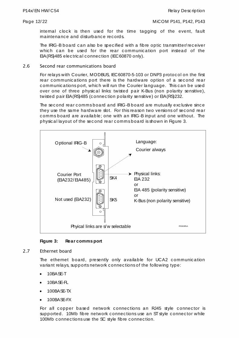
P14x/EN HW/C54 Relay Description Page 12/22 MiCOM P141, P142, P143
internal clock is then used for the time tagging of the event, fault maintenance and disturbance records.
The IRIG-B board can also be specified with a fibre optic transmitter/receiver which can be used for the rear communication port instead of the EIA(RS)485 electrical connection (IEC60870 only).
2.6 Second rear communications board For relays with Courier, MODBUS, IEC60870-5-103 or DNP3 protocol on the first rear communications port there is the hardware option of a second rear communications port, which will run the Courier language. This can be used over one of three physical links: twisted pair K-Bus (non polarity sensitive), twisted pair EIA(RS)485 (connection polarity sensitive) or EIA(RS)232.
The second rear comms board and IRIG-B board are mutually exclusive since they use the same hardware slot. For this reason two versions of second rear comms board are available; one with an IRIG-B input and one without. The physical layout of the second rear comms board is shown in Figure 3.
Language:
Courier always
Physical links:EIA 232 or EIA 485 (polarity sensitive) or K-Bus (non polarity sensitive)SK5
SK4
Phyical links are s/w selectable
Optional IRIG-B
Courier Port (EIA232/ EIA485)
Not used (EIA232)
P2083ENA
Figure 3: Rear comms port
2.7 Ethernet board The ethernet board, presently only available for UCA2 communication variant relays, supports network connections of the following type:
10BASE-T
10BASE-FL
100BASE-TX
100BASE-FX
For all copper based network connections an RJ45 style connector is supported. 10Mb fibre network connections use an ST style connector while 100Mb connections use the SC style fibre connection.
Relay Description P14x/EN HW/C54 MiCOM P141, P142, P143 Page 13/22
An extra processor, a Motorola PPC, and memory block is fitted to the ethernet card that is responsible for running all the network related functions such as TCP/IP / OSI as supplied by VxWorks and the UCA2/MMS server as supplied by Sisco inc. The extra memory block also holds the UCA2 data model supported by the relay.
2.8 Mechanical layout The case materials of the relay are constructed from pre-finished steel which has a conductive covering of aluminium and zinc. This provides good earthing at all joints giving a low impedance path to earth which is essential for performance in the presence of external noise. The boards and modules use a multi-point earthing strategy to improve the immunity to external noise and minimise the effect of circuit noise. Ground planes are used on boards to reduce impedance paths and spring clips are used to ground the module metalwork.
Heavy duty terminal blocks are used at the rear of the relay for the current and voltage signal connections. Medium duty terminal blocks are used for the digital logic input signals, the output relay contacts, the power supply and the rear communication port. A BNC connector is used for the optional IRIG-B signal. 9-pin and 25-pin female D-connectors are used at the front of the relay for data communication.
Inside the relay the PCBs plug into the connector blocks at the rear, and can be removed from the front of the relay only. The connector blocks to the relay’s CT inputs are provided with internal shorting links inside the relay which will automatically short the current transformer circuits before they are broken when the board is removed.
The front panel consists of a membrane keypad with tactile dome keys, an LCD and 12 LEDs mounted on an aluminium backing plate.
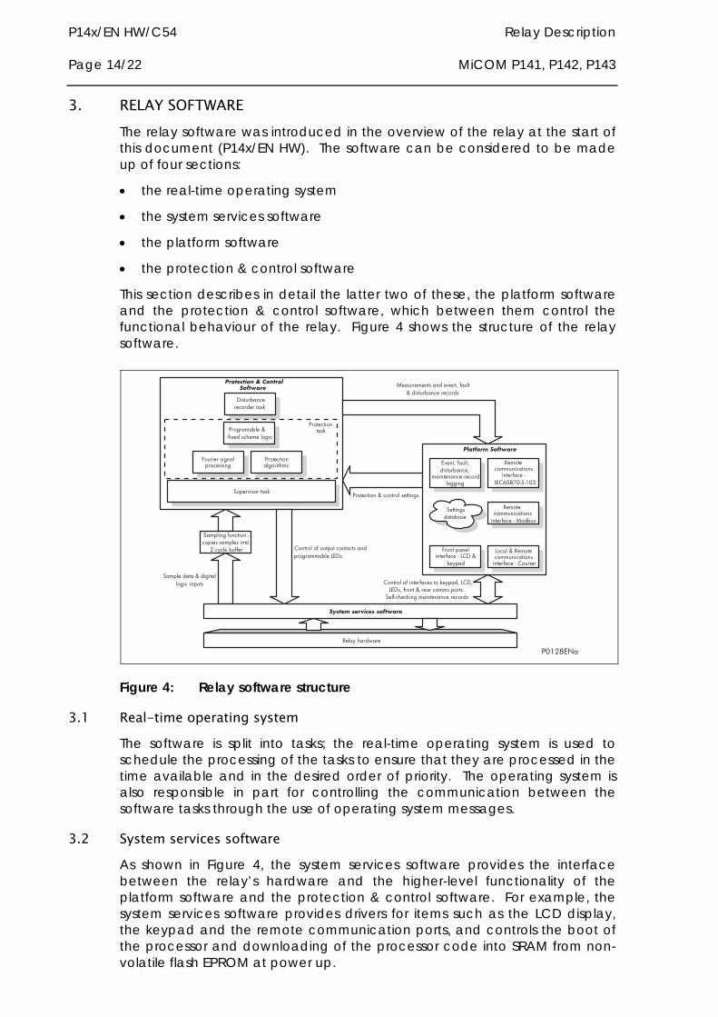
P14x/EN HW/C54 Relay Description Page 14/22 MiCOM P141, P142, P143
3. RELAY SOFTWARE The relay software was introduced in the overview of the relay at the start of this document (P14x/EN HW). The software can be considered to be made up of four sections:
the real-time operating system
the system services software
the platform software
the protection & control software
This section describes in detail the latter two of these, the platform software and the protection & control software, which between them control the functional behaviour of the relay. Figure 4 shows the structure of the relay software.
�78'0�:�
������������ ��������
� ������������ ������
�� ����� �� ������
��������������� ��������
�� ���������������������� ���
�������������������������������������� ���
����������������������
�������� ��
!��������������������
���������� ��� ����
�� �������������"�#$���
�����
%�����������
��� ��� ������� ���������"
&!$'()*("+",(-
� ��������������
%������� ������� ����� ���� �� ���������
%����������������� ��������� $ �� �� ������������ ��������#$��
#!������ ��������� ����� ���.%���"������������������ ���
%����������� �"� �������������� /�������������
��� ��� ������� ���������"�� ����
# �������� ��� ������� ���������"�$ �����
�� ����� ���
$ �� �� �� ������� �������� ��������#!��
Figure 4: Relay software structure
3.1 Real-time operating system The software is split into tasks; the real-time operating system is used to schedule the processing of the tasks to ensure that they are processed in the time available and in the desired order of priority. The operating system is also responsible in part for controlling the communication between the software tasks through the use of operating system messages.
3.2 System services software As shown in Figure 4, the system services software provides the interface between the relay’s hardware and the higher-level functionality of the platform software and the protection & control software. For example, the system services software provides drivers for items such as the LCD display, the keypad and the remote communication ports, and controls the boot of the processor and downloading of the processor code into SRAM from non-volatile flash EPROM at power up.
Relay Description P14x/EN HW/C54 MiCOM P141, P142, P143 Page 15/22
3.3 Platform software The platform software has three main functions:
to control the logging of records that are generated by the protection software, including alarms and event, fault, and maintenance records.
to store and maintain a database of all of the relay’s settings in non-volatile memory.
to provide the internal interface between the settings database and each of the relay’s user interfaces, i.e. the front panel interface and the front and rear communication ports, using whichever communication protocol has been specified (Courier, MODBUS, IEC 60870-5-103 and DNP3.0).
3.3.1 Record logging
The logging function is provided to store all alarms, events, faults and maintenance records. The records for all of these incidents are logged in battery backed-up SRAM in order to provide a non-volatile log of what has happened. The relay maintains four logs: one each for up to 32 alarms, 512 event records, 5 fault records and 5 maintenance records. The logs are maintained such that the oldest record is overwritten with the newest record. The logging function can be initiated from the protection software or the platform software is responsible for logging of a maintenance record in the event of a relay failure. This includes errors that have been detected by the platform software itself or error that are detected by either the system services or the protection software function. See also the section on supervision and diagnostics later in this document (P14x/EN HW).
3.3.2 Settings database
The settings database contains all of the settings and data for the relay, including the protection, disturbance recorder and control & support settings. The settings are maintained in non-volatile memory. The platform software’s management of the settings database includes the responsibility of ensuring that only one user interface modifies the settings of the database at any one time. This feature is employed to avoid conflict between different parts of the software during a setting change. For changes to protection settings and disturbance recorder settings, the platform software operates a ‘scratchpad’ in SRAM memory. This allows a number of setting changes to be applied to the protection elements, disturbance recorder and saved in the database in non-volatile memory. (See also the Introduction to this manual (P14x/EN IT) on the user interface). If a setting change affects the protection & control task, the database advises it of the new values.
3.3.3 Database interface
The other function of the platform software is to implement the relay’s internal interface between the database and each of the relay’s user interfaces. The database of settings and measurements must be accessible from all of the relay’s user interfaces to allow read and modify operations. The platform software presents the data in the appropriate format for each user interface.
P14x/EN HW/C54 Relay Description Page 16/22 MiCOM P141, P142, P143
3.4 Protection and control software The protection and control software task is responsible for processing all of the protection elements and measurement functions of the relay. To achieve this it has to communicate with both the system services software and the platform software as well as organise its own operations. The protection software has the highest priority of any of the software tasks in the relay in order to provide the fastest possible protection response. The protection & control software has a supervisor task which controls the start-up of the task and deals with the exchange of messages between the task and the platform software.
3.4.1 Overview - protection and control scheduling
After initialisation at start-up, the protection and control task is suspended until there are sufficient samples available for it to process. The acquisition of samples is controlled by a ‘sampling function’ which is called by the system services software and takes each set of new samples from the input module and stores them in a two-cycle buffer. The protection and control software resumes execution when the number of unprocessed samples in the buffer reaches a certain number. For the P140 feeder protection relay, the protection task is executed twice per cycle, i.e. after every 12 samples for the sample rate of 24 samples per power cycle used by the relay. The protection and control software is suspended again when all of its processing on a set of samples is complete. This allows operations by other software tasks to take place.
3.4.2 Signal processing
The sampling function provides filtering of the digital input signals from the opto-isolators and frequency tracking of the analog signals. The digital inputs are checked against their previous value over a period of half a cycle. Hence a change in the state of one of the inputs must be maintained over at least half a cycle before it is registered with the protection and control software.
The frequency tracking of the analog input signals is achieved by a recursive Fourier algorithm which is applied to one of the input signals, and works by detecting a change in the measured signal’s phase angle. The calculated value of the frequency is used to modify the sample rate being used by the input module so as to achieve a constant sample rate of 24 samples per cycle of the power waveform. The value of the frequency is also stored for use by the protection and control task.
When the protection and control task is re-started by the sampling function, it calculates the Fourier components for the analog signals. The Fourier components are calculated using a one-cycle, 24-sample Discrete Fourier Transform (DFT). The DFT is always calculated using the last cycle of samples from the 2-cycle buffer, i.e. the most recent data is used. The DFT used in this way extracts the power frequency fundamental component from the signal and produces the magnitude and phase angle of the fundamental in rectangular component format. The DFT provides an accurate measurement of the fundamental frequency component, and effective filtering of harmonic frequencies and noise. This performance is achieved in conjunction with the relay input module which provides hardware anti-alias filtering to attenuate frequencies above the half sample rate, and frequency
Relay Description P14x/EN HW/C54 MiCOM P141, P142, P143 Page 17/22
tracking to maintain a sample rate of 24 samples per cycle. The Fourier components of the input current and voltage signals are stored in memory so that they can be accessed by all of the protection elements’ algorithms. The samples from the input module are also used in an unprocessed form by the disturbance recorder for waveform recording and to calculate true rms values of current, voltage and power for metering purposes.
3.4.3 Programmable scheme logic
The purpose of the programmable scheme logic (PSL) is to allow the relay user to configure an individual protection scheme to suit their own particular application. This is achieved through the use of programmable logic gates and delay timers.
The input to the PSL is any combination of the status of the digital input signals from the opto-isolators on the input board, the outputs of the protection elements, e.g. protection starts and trips, and the outputs of the fixed protection scheme logic. The fixed scheme logic provides the relay’s standard protection schemes. The PSL itself consists of software logic gates and timers. The logic gates can be programmed to perform a range of different logic functions and can accept any number of inputs. The timers are used either to create a programmable delay, and/or to condition the logic outputs, e.g. to create a pulse of fixed duration on the output regardless of the length of the pulse on the input. The outputs of the PSL are the LEDs on the front panel of the relay and the output contacts at the rear.
The execution of the PSL logic is event driven; the logic is processed whenever any of its inputs change, for example as a result of a change in one of the digital input signals or a trip output from a protection element. Also, only the part of the PSL logic that is affected by the particular input change that has occurred is processed. This reduces the amount of processing time that is used by the PSL. The protection and control software updates the logic delay timers and checks for a change in the PSL input signals every time it runs.
This system provides flexibility for the user to create their own scheme logic design. However, it also means that the PSL can be configured into a very complex system, and because of this setting of the PSL is implemented through the PC support package MiCOM S1.
3.4.4 Event and fault recording
A change in any digital input signal or protection element output signal causes an event record to be created. When this happens, the protection and control task sends a message to the supervisor task to indicate that an event is available to be processed and writes the event data to a fast buffer in SRAM which is controlled by the supervisor task. When the supervisor task receives either an event or fault record message, it instructs the platform software to create the appropriate log in battery backed-up SRAM. The operation of the record logging to battery backed-up SRAM is slower than the supervisor’s buffer. This means that the protection software is not delayed waiting for the records to be logged by the platform software. However, in the rare case when a large number of records to be logged are created in a short period of time, it is possible that some will be lost if the supervisor’s buffer is full before the platform software is able to create a new log in battery backed-up SRAM. If this occurs then an event is logged to indicate this loss of information.
P14x/EN HW/C54 Relay Description Page 18/22 MiCOM P141, P142, P143
3.4.5 Disturbance recorder
The disturbance recorder operates as a separate task from the protection and control task. It can record the waveforms for up to 8 analog channels and the values of up to 32 digital signals. The recording time is user selectable up to a maximum of 10 seconds. The disturbance recorder is supplied with data by the protection and control task once per cycle. The disturbance recorder collates the data that it receives into the required length disturbance record. The disturbance records can be extracted by MiCOM S1 which can also store the data in COMTRADE format, thus allowing the use of other packages to view the recorded data.
3.4.6 Fault locator
The fault locator task is also separate from the protection and control task. The fault locator is invoked by the protection and control task when a fault is detected. The fault locator uses a 12-cycle buffer of the analog input signals and returns the calculated location of the fault to the protection and control task which includes it in the fault record for the fault. When the fault record is complete (i.e. includes the fault location), the protection and control task can send a message to the supervisor task to log the fault record.
Relay Description P14x/EN HW/C54 MiCOM P141, P142, P143 Page 19/22
4. SELF TESTING & DIAGNOSTICS The relay includes a number of self-monitoring functions to check the operation of its hardware and software when it is in service. These are included so that if an error or fault occurs within the relay’s hardware or software, the relay is able to detect and report the problem and attempt to resolve it by performing a re-boot. This involves the relay being out of service for a short period of time which is indicated by the ‘Healthy’ LED on the front of the relay being extinguished and the watchdog contact at the rear operating. If the restart fails to resolve the problem, then the relay will take itself permanently out of service. Again this will be indicated by the LED and watchdog contact.
If a problem is detected by the self-monitoring functions, the relay attempts to store a maintenance record in battery backed-up SRAM to allow the nature of the problem to be notified to the user.
The self-monitoring is implemented in two stages: firstly a thorough diagnostic check which is performed when the relay is booted-up, e.g. at power-on, and secondly a continuous self-checking operation which checks the operation of the relay’s critical functions whilst it is in service.
4.1 Start-up self-testing The self-testing which is carried out when the relay is started takes a few seconds to complete, during which time the relay’s protection is unavailable. This is signalled by the ‘Healthy’ LED on the front of the relay which will illuminate when the relay has passed all of the tests and entered operation. If the testing detects a problem, the relay will remain out of service until it is manually restored to working order.
The operations that are performed at start-up are as follows:
4.1.1 System boot
The integrity of the flash EPROM memory is verified using a checksum before the program code and data stored in it is copied into SRAM to be used for execution by the processor. When the copy has been completed the data then held in SRAM is compared to that in the flash EPROM to ensure that the two are the same and that no errors have occurred in the transfer of data from flash EPROM to SRAM. The entry point of the software code in SRAM is then called which is the relay initialisation code.
4.1.2 Initialisation software
The initialisation process includes the operations of initialising the processor registers and interrupts, starting the watchdog timers (used by the hardware to determine whether the software is still running), starting the real-time operating system and creating and starting the supervisor task. In the course of the initialisation process the relay checks:
the status of the battery.
the integrity of the battery backed-up SRAM that is used to store event, fault and disturbance records.
the voltage level of the field voltage supply which is used to drive the opto-isolated inputs.
P14x/EN HW/C54 Relay Description Page 20/22 MiCOM P141, P142, P143
the operation of the LCD controller.
the watchdog operation.
At the conclusion of the initialisation software the supervisor task begins the process of starting the platform software.
4.1.3 Platform software initialisation & monitoring
In starting the platform software, the relay checks the integrity of the data held in non-volatile memory with a checksum, the operation of the real-time clock, and the IRIG-B board if fitted. The final test that is made concerns the input and output of data; the presence and healthy condition of the input board is checked and the analog data acquisition system is checked through sampling the reference voltage.
At the successful conclusion of all of these tests the relay is entered into service and the protection started-up.
4.2 Continuous self-testing When the relay is in service, it continually checks the operation of the critical parts of its hardware and software. The checking is carried out by the system services software (see section on relay software earlier in this document (P14x/EN HW)) and the results reported to the platform software. The functions that are checked are as follows:
the flash EPROM containing all program code and language text is verified by a checksum.
the code and constant data held in SRAM is checked against the corresponding data in flash EPROM to check for data corruption.
the SRAM containing all data other than the code and constant data is verified with a checksum.
the E2PROM containing setting values is verified by a checksum, whenever its data is accessed.
the battery status.
the level of the field voltage.
the integrity of the digital signal I/O data from the opto-isolated inputs and the relay contacts is checked by the data acquisition function every time it is executed. The operation of the analog data acquisition system is continuously checked by the acquisition function every time it is executed, by means of sampling the reference voltages.
the operation of the IRIG-B board is checked, where it is fitted, by the software that reads the time and date from the board.
The operation of the ethernet board is checked, where it is fitted, by the software on the main processor card. If the ethernet board fails to respond an alarm is raised and the card is reset in an attempt to resolve the problem.
In the unlikely event that one of the checks detects an error within the relay’s subsystems, the platform software is notified and it will attempt to log a maintenance record in battery backed-up SRAM. If the problem is with the battery status or the IRIG-B board, the relay will continue in operation.

Relay Description P14x/EN HW/C54 MiCOM P141, P142, P143 Page 21/22
However, for problems detected in any other area the relay will initiate a shutdown and re-boot. This will result in a period of up to 5 seconds when the protection is unavailable, but the complete restart of the relay including all initialisations should clear most problems that could occur. As described above, an integral part of the start-up procedure is a thorough diagnostic self-check. If this detects the same problem that caused the relay to restart, i.e. the restart has not cleared the problem, then the relay will take itself permanently out of service. This is indicated by the ‘Healthy’ LED on the front of the relay, which will extinguish, and the watchdog contact which will operate.

P14x/EN HW/C54 Relay Description Page 22/22 MiCOM P141, P142, P143
Technical Data P14x/EN TD/C54 MiCOM P141, P42, P143
TECHNICAL DATA

P14x/EN TD/C54 Technical Data MiCOM P141, P142, P143
Technical Data P14x/EN TD/C54 MiCOM P141, P142, P143 Page 1/58
CONTENT
1. RATINGS 7
1.1 Currents 7
1.2 Voltages 7
1.3 Auxiliary voltage 8
1.4 Frequency 8
1.5 ‘Universal’ logic inputs (P140 range) 8
1.6 Output relay contacts 9
1.7 Field voltage 10
1.8 Loop through connections 10
1.9 Wiring requirements 10
2. BURDENS 11
2.1 Current circuit 11
2.2 Voltage circuit 11
2.3 Auxiliary supply 11
2.4 Optically-isolated inputs 11
3. ACCURACY 12
3.1 Reference conditions 12
3.2 Influencing quantities 12
4. HIGH VOLTAGE WITHSTAND 14
4.1 Dielectric withstand 14
4.2 Impulse 14
4.3 Insulation resistance 14
4.4 ANSI dielectric withstand 14
5. ELECTRICAL ENVIRONMENT 15
5.1 Performance criteria 15
5.1.1 Class A 15
5.1.2 Class B 15
P14x/EN TD/C54 Technical Data Page 2/58 MiCOM P141, P142, P143
5.1.3 Class C 15
5.2 Auxiliary supply tests, dc interruption, etc. 15
5.2.1 DC voltage interruptions 15
5.2.2 DC voltage fluctuations 16
5.3 AC voltage dips and short interruptions 16
5.3.1 AC voltage short interruptions 16
5.3.2 AC voltage dips 16
5.4 High frequency disturbance 16
5.5 Fast transients 17
5.6 Conducted/radiated emissions 17
5.6.1 Conducted emissions 17
5.6.2 Radiated emissions 17
5.7 Conducted/radiated immunity 17
5.7.1 Conducted immunity 17
5.7.2 Radiated immunity 17
5.7.3 Radiated immunity from digital radio telephones 17
5.8 Electrostatic discharge 18
5.9 Surge immunity 18
5.10 Power frequency magnetic field 18
5.11 Power frequency interference 18
5.12 Surge withstand capability (SWC) 19
5.13 Radiated immunity 19
6. ATMOSPHERIC ENVIRONMENT 19
6.1 Temperature 19
6.2 Humidity 19
6.3 Enclosure protection 20
7. MECHANICAL ENVIRONMENT 21
7.1 Performance criteria 21
7.1.1 Severity classes 21
7.1.2 Vibration (sinusoidal) 21
7.1.3 Shock and bump 22
Technical Data P14x/EN TD/C54 MiCOM P141, P142, P143 Page 3/58
7.1.4 Seismic 22
8. EC EMC COMPLIANCE 23
9. EC LVD COMPLIANCE 23
10. PROTECTION FUNCTIONS 23
10.1 Three phase non-directional/directional overcurrent protection (50/51) (67) 23
10.1.1 Setting ranges 23
10.1.2 Time delay settings 23
10.1.3 Transient overreach and overshoot 24
10.2 Inverse time (IDMT) characteristic 24
10.2.1 Time multiplier settings for IEC/UK curves 25
10.2.2 Time dial settings for IEEE/US curves 26
10.2.3 Definite time characteristic 26
10.2.4 Reset characteristics 26
10.2.5 RI Curve 26
10.2.6 Accuracy 27
10.2.7 IEC curves 28
10.3 Earth fault & sensitive earth fault protection (50N/51N) (67N) (64) 29
10.3.1 Setting ranges 30
10.3.2 EF and SEF time delay characteristics 31
10.3.3 IDG Curve 32
10.3.4 Wattmetric SEF settings (zero sequence power settings) 32
10.3.5 Accuracy 33
10.4 Negative sequence overcurrent 35
10.4.1 Setting ranges 35
10.4.2 Accuracy 35
10.5 Undervoltage protection 35
10.5.1 Level settings 35
10.5.2 Undervoltage protection time delay characteristics 35
10.5.3 Accuracy 36
10.6 Overvoltage protection 36
10.6.1 Level settings 36
P14x/EN TD/C54 Technical Data Page 4/58 MiCOM P141, P142, P143
10.6.2 Overvoltage protection time delay characteristics 36
10.6.3 Accuracy 37
10.7 Neutral displacement/residual overvoltage 37
10.7.1 Setting ranges 37
10.7.2 Neutral displacement/residual overvoltage protection time delay characteristics 37
10.7.3 Accuracy 38
10.8 Under-frequency protection 38
10.8.1 Level settings 38
10.8.2 Accuracy 38
10.9 Overfrequency protection 39
10.9.1 Level settings 39
10.9.2 Accuracy 39
10.10 DF/DT protection (software versions 0210G and 0300J only) 39
10.10.1 Level settings 39
10.10.2 Accuracy 39
10.11 Broken conductor logic 39
10.11.1 Setting ranges 39
10.11.2 Accuracy 39
10.12 Thermal overload 40
10.12.1 Setting ranges 40
10.12.2 Accuracy 40
10.13 Voltage controlled overcurrent 41
10.13.1 Setting range 41
10.13.2 Accuracy 41
10.14 Cold load pick-up settings 41
10.14.1 Setting range 41
10.14.2 Accuracy 41
10.15 Negative sequence overvoltage protection 42
10.15.1 Setting range 42
10.15.2 Accuracy 42
10.16 Admittance, conductance and susceptance 42
10.16.1 Setting range 42
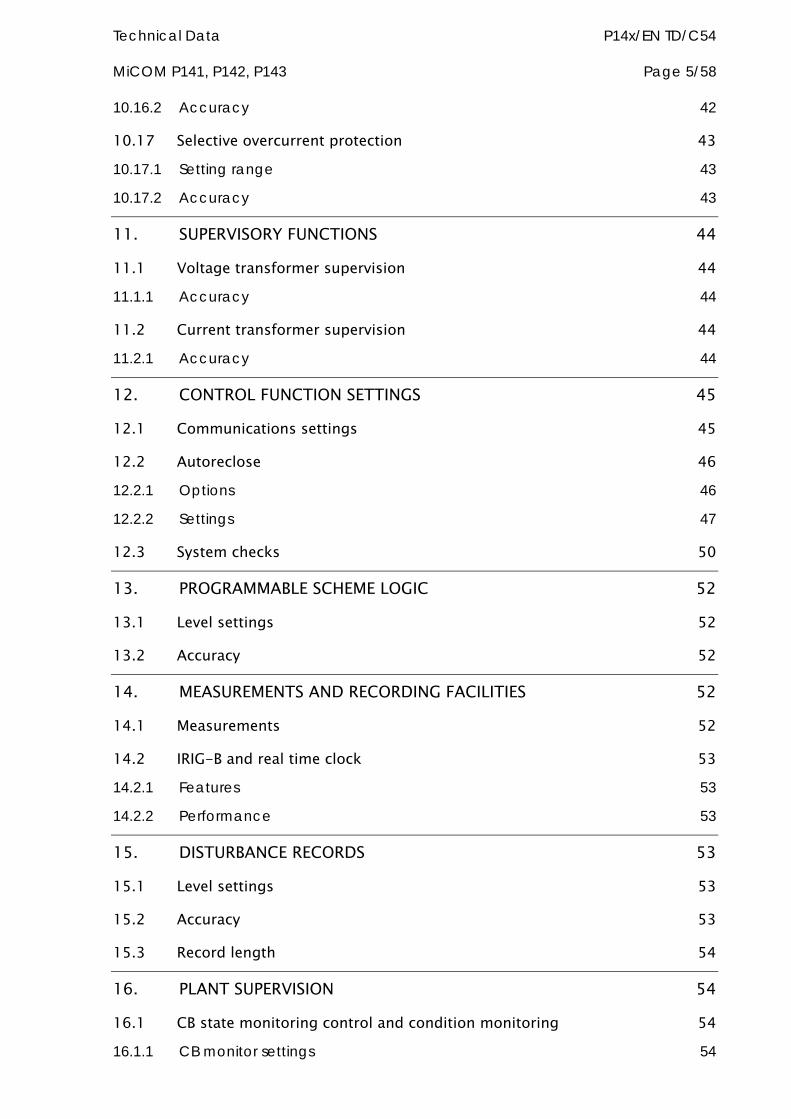
Technical Data P14x/EN TD/C54 MiCOM P141, P142, P143 Page 5/58
10.16.2 Accuracy 42
10.17 Selective overcurrent protection 43
10.17.1 Setting range 43
10.17.2 Accuracy 43
11. SUPERVISORY FUNCTIONS 44
11.1 Voltage transformer supervision 44
11.1.1 Accuracy 44
11.2 Current transformer supervision 44
11.2.1 Accuracy 44
12. CONTROL FUNCTION SETTINGS 45
12.1 Communications settings 45
12.2 Autoreclose 46
12.2.1 Options 46
12.2.2 Settings 47
12.3 System checks 50
13. PROGRAMMABLE SCHEME LOGIC 52
13.1 Level settings 52
13.2 Accuracy 52
14. MEASUREMENTS AND RECORDING FACILITIES 52
14.1 Measurements 52
14.2 IRIG-B and real time clock 53
14.2.1 Features 53
14.2.2 Performance 53
15. DISTURBANCE RECORDS 53
15.1 Level settings 53
15.2 Accuracy 53
15.3 Record length 54
16. PLANT SUPERVISION 54
16.1 CB state monitoring control and condition monitoring 54
16.1.1 CB monitor settings 54
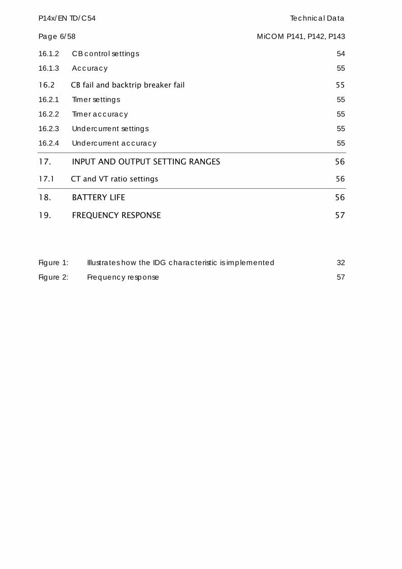
P14x/EN TD/C54 Technical Data Page 6/58 MiCOM P141, P142, P143
16.1.2 CB control settings 54
16.1.3 Accuracy 55
16.2 CB fail and backtrip breaker fail 55
16.2.1 Timer settings 55
16.2.2 Timer accuracy 55
16.2.3 Undercurrent settings 55
16.2.4 Undercurrent accuracy 55
17. INPUT AND OUTPUT SETTING RANGES 56
17.1 CT and VT ratio settings 56
18. BATTERY LIFE 56
19. FREQUENCY RESPONSE 57
Figure 1: Illustrates how the IDG characteristic is implemented 32
Figure 2: Frequency response 57
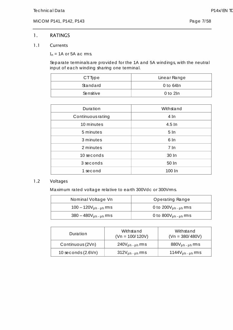
Technical Data P14x/EN TD MiCOM P141, P142, P143 Page 7/58
1. RATINGS
1.1 Currents n = 1A or 5A ac rms.
Separate terminals are provided for the 1A and 5A windings, with the neutral input of each winding sharing one terminal.
CT Type Linear Range
Standard 0 to 64n
Sensitive 0 to 2n
Duration Withstand
Continuous rating 4 n
10 minutes 4.5 n
5 minutes 5 n
3 minutes 6 n
2 minutes 7 n
10 seconds 30 n
3 seconds 50 n
1 second 100 n
1.2 Voltages Maximum rated voltage relative to earth 300Vdc or 300Vrms.
Nominal Voltage Vn Operating Range
100 – 120Vph - ph rms 0 to 200Vph - ph rms
380 – 480Vph - ph rms 0 to 800Vph - ph rms
Duration Withstand (Vn = 100/120V)
Withstand (Vn = 380/480V)
Continuous (2Vn) 240Vph - ph rms 880Vph - ph rms
10 seconds (2.6Vn) 312Vph - ph rms 1144Vph - ph rms
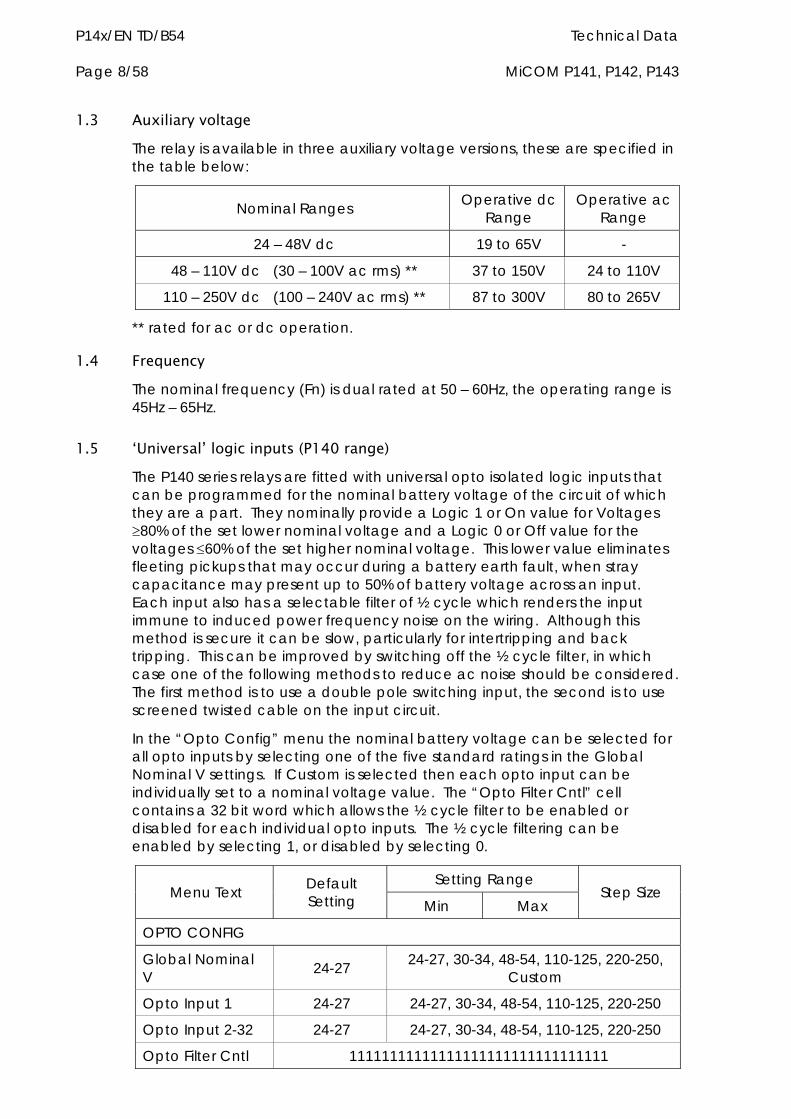
P14x/EN TD/B54 Technical Data Page 8/58 MiCOM P141, P142, P143
1.3 Auxiliary voltage The relay is available in three auxiliary voltage versions, these are specified in the table below:
Nominal Ranges Operative dc Range
Operative ac Range
24 – 48V dc 19 to 65V -
48 – 110V dc (30 – 100V ac rms) ** 37 to 150V 24 to 110V
110 – 250V dc (100 – 240V ac rms) ** 87 to 300V 80 to 265V
** rated for ac or dc operation.
1.4 Frequency The nominal frequency (Fn) is dual rated at 50 – 60Hz, the operating range is 45Hz – 65Hz.
1.5 ‘Universal’ logic inputs (P140 range) The P140 series relays are fitted with universal opto isolated logic inputs that can be programmed for the nominal battery voltage of the circuit of which they are a part. They nominally provide a Logic 1 or On value for Voltages 80% of the set lower nominal voltage and a Logic 0 or Off value for the voltages 60% of the set higher nominal voltage. This lower value eliminates fleeting pickups that may occur during a battery earth fault, when stray capacitance may present up to 50% of battery voltage across an input. Each input also has a selectable filter of ½ cycle which renders the input immune to induced power frequency noise on the wiring. Although this method is secure it can be slow, particularly for intertripping and back tripping. This can be improved by switching off the ½ cycle filter, in which case one of the following methods to reduce ac noise should be considered. The first method is to use a double pole switching input, the second is to use screened twisted cable on the input circuit.
In the “Opto Config” menu the nominal battery voltage can be selected for all opto inputs by selecting one of the five standard ratings in the Global Nominal V settings. If Custom is selected then each opto input can be individually set to a nominal voltage value. The “Opto Filter Cntl” cell contains a 32 bit word which allows the ½ cycle filter to be enabled or disabled for each individual opto inputs. The ½ cycle filtering can be enabled by selecting 1, or disabled by selecting 0.
Setting Range Menu Text Default
Setting Min Max Step Size
OPTO CONFIG
Global Nominal V 24-27 24-27, 30-34, 48-54, 110-125, 220-250,
Custom
Opto Input 1 24-27 24-27, 30-34, 48-54, 110-125, 220-250
Opto Input 2-32 24-27 24-27, 30-34, 48-54, 110-125, 220-250
Opto Filter Cntl 11111111111111111111111111111111
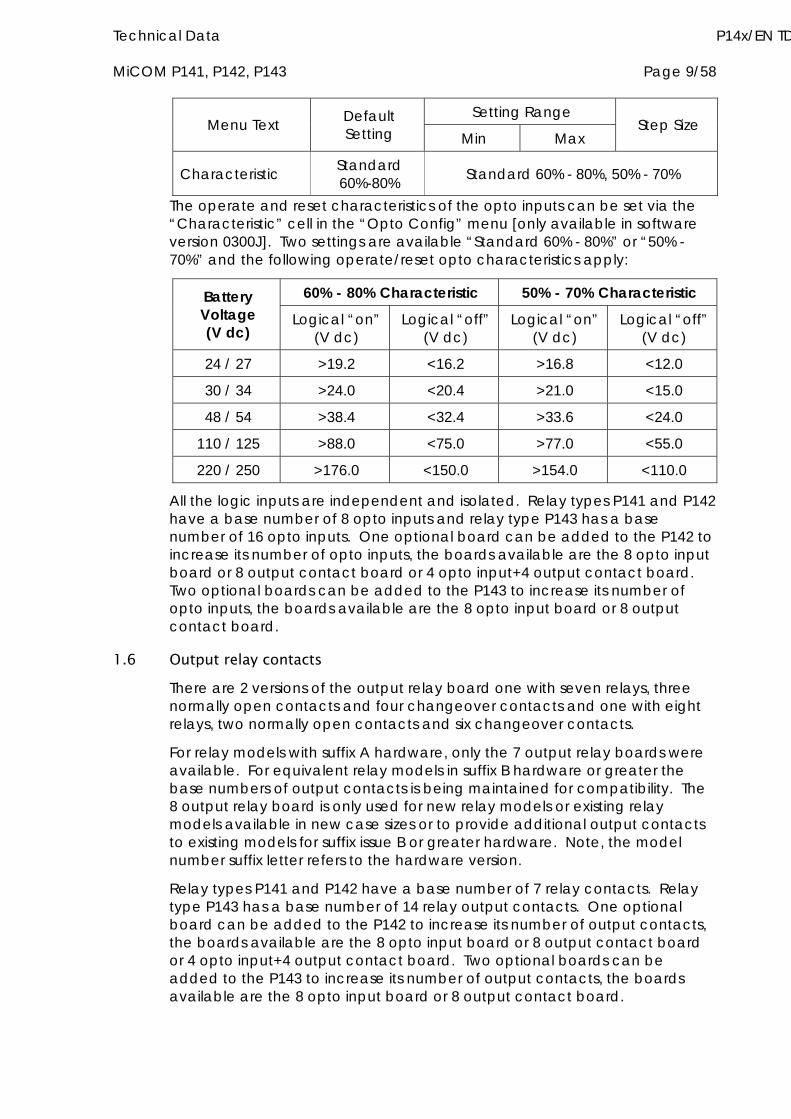
Technical Data P14x/EN TD MiCOM P141, P142, P143 Page 9/58
Setting Range Menu Text Default
Setting Min Max Step Size
Characteristic Standard 60%-80% Standard 60% - 80%, 50% - 70%
The operate and reset characteristics of the opto inputs can be set via the “Characteristic” cell in the “Opto Config” menu [only available in software version 0300J]. Two settings are available “Standard 60% - 80%” or “50% - 70%” and the following operate/reset opto characteristics apply:
60% - 80% Characteristic 50% - 70% Characteristic Battery Voltage (V dc)
Logical “on” (V dc)
Logical “off” (V dc)
Logical “on” (V dc)
Logical “off” (V dc)
24 / 27 >19.2 <16.2 >16.8 <12.0
30 / 34 >24.0 <20.4 >21.0 <15.0
48 / 54 >38.4 <32.4 >33.6 <24.0
110 / 125 >88.0 <75.0 >77.0 <55.0
220 / 250 >176.0 <150.0 >154.0 <110.0
All the logic inputs are independent and isolated. Relay types P141 and P142 have a base number of 8 opto inputs and relay type P143 has a base number of 16 opto inputs. One optional board can be added to the P142 to increase its number of opto inputs, the boards available are the 8 opto input board or 8 output contact board or 4 opto input+4 output contact board. Two optional boards can be added to the P143 to increase its number of opto inputs, the boards available are the 8 opto input board or 8 output contact board.
1.6 Output relay contacts There are 2 versions of the output relay board one with seven relays, three normally open contacts and four changeover contacts and one with eight relays, two normally open contacts and six changeover contacts.
For relay models with suffix A hardware, only the 7 output relay boards were available. For equivalent relay models in suffix B hardware or greater the base numbers of output contacts is being maintained for compatibility. The 8 output relay board is only used for new relay models or existing relay models available in new case sizes or to provide additional output contacts to existing models for suffix issue B or greater hardware. Note, the model number suffix letter refers to the hardware version.
Relay types P141 and P142 have a base number of 7 relay contacts. Relay type P143 has a base number of 14 relay output contacts. One optional board can be added to the P142 to increase its number of output contacts, the boards available are the 8 opto input board or 8 output contact board or 4 opto input+4 output contact board. Two optional boards can be added to the P143 to increase its number of output contacts, the boards available are the 8 opto input board or 8 output contact board.
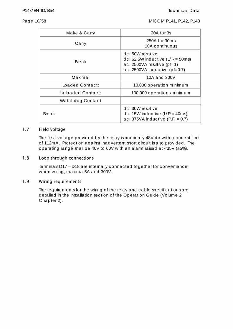
P14x/EN TD/B54 Technical Data Page 10/58 MiCOM P141, P142, P143
Make & Carry 30A for 3s
Carry 250A for 30ms 10A continuous
Break
dc: 50W resistive dc: 62.5W inductive (L/R = 50ms) ac: 2500VA resistive (pf=1) ac: 2500VA inductive (pf=0.7)
Maxima: 10A and 300V
Loaded Contact: 10,000 operation minimum
Unloaded Contact: 100,000 operations minimum
Watchdog Contact
Break dc: 30W resistive dc: 15W inductive (L/R = 40ms) ac: 375VA inductive (P.F. = 0.7)
1.7 Field voltage The field voltage provided by the relay is nominally 48V dc with a current limit of 112mA. Protection against inadvertent short circuit is also provided. The operating range shall be 40V to 60V with an alarm raised at <35V (5%).
1.8 Loop through connections Terminals D17 – D18 are internally connected together for convenience when wiring, maxima 5A and 300V.
1.9 Wiring requirements The requirements for the wiring of the relay and cable specifications are detailed in the installation section of the Operation Guide (Volume 2 Chapter 2).
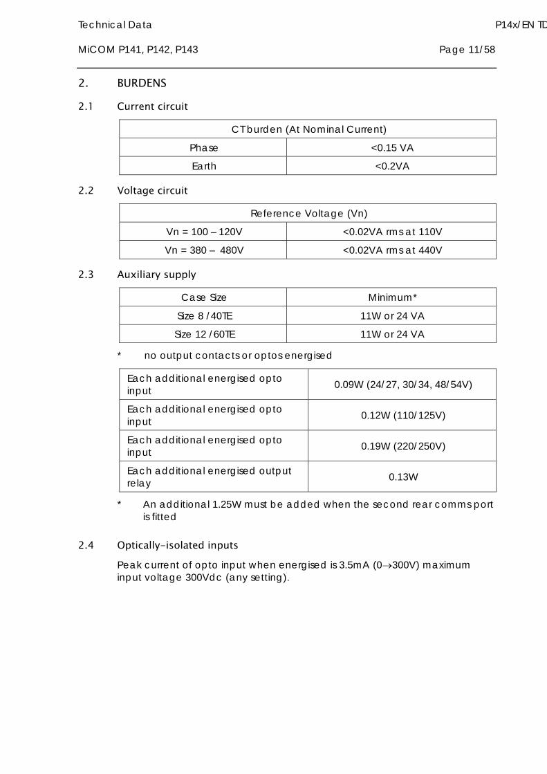
Technical Data P14x/EN TD MiCOM P141, P142, P143 Page 11/58
2. BURDENS
2.1 Current circuit
CT burden (At Nominal Current)
Phase <0.15 VA
Earth <0.2VA
2.2 Voltage circuit
Reference Voltage (Vn)
Vn = 100 – 120V <0.02VA rms at 110V
Vn = 380 – 480V <0.02VA rms at 440V
2.3 Auxiliary supply
Case Size Minimum*
Size 8 /40TE 11W or 24 VA
Size 12 /60TE 11W or 24 VA
* no output contacts or optos energised
Each additional energised opto input 0.09W (24/27, 30/34, 48/54V)
Each additional energised opto input 0.12W (110/125V)
Each additional energised opto input 0.19W (220/250V)
Each additional energised output relay 0.13W
* An additional 1.25W must be added when the second rear comms port is fitted
2.4 Optically-isolated inputs Peak current of opto input when energised is 3.5mA (0300V) maximum input voltage 300Vdc (any setting).
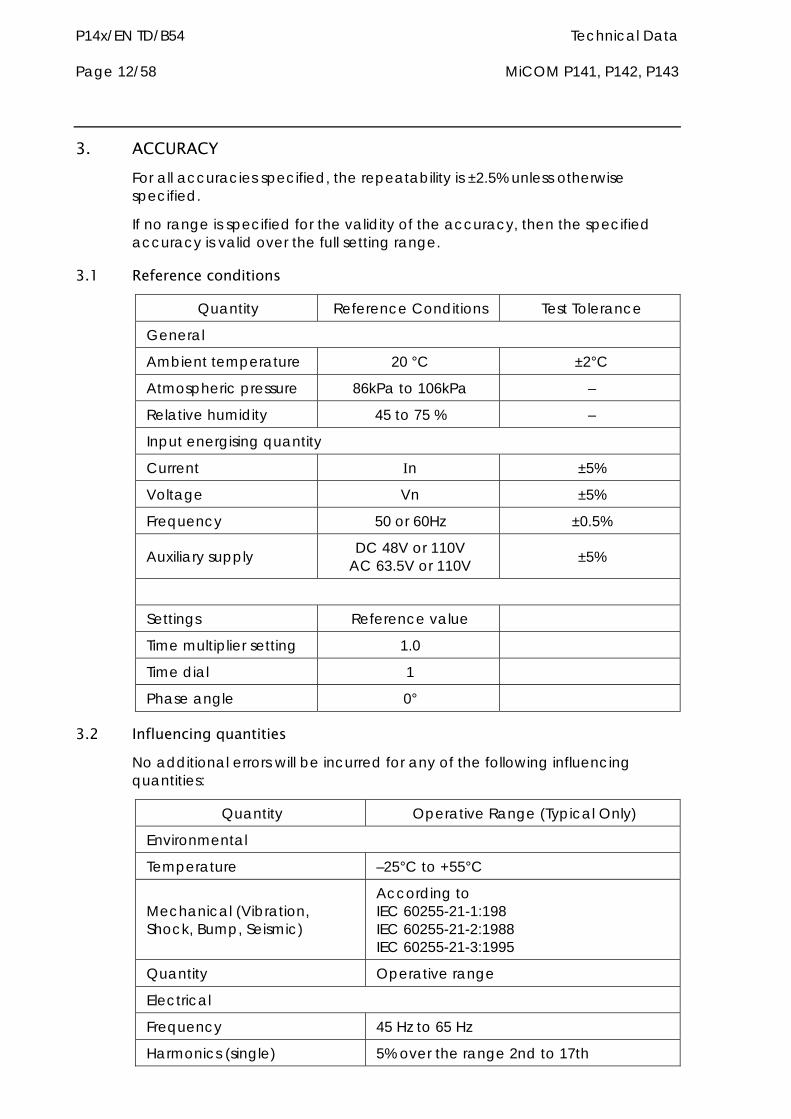
P14x/EN TD/B54 Technical Data Page 12/58 MiCOM P141, P142, P143
3. ACCURACY For all accuracies specified, the repeatability is ±2.5% unless otherwise specified.
If no range is specified for the validity of the accuracy, then the specified accuracy is valid over the full setting range.
3.1 Reference conditions
Quantity Reference Conditions Test Tolerance
General
Ambient temperature 20 °C ±2°C
Atmospheric pressure 86kPa to 106kPa –
Relative humidity 45 to 75 % –
Input energising quantity
Current n ±5%
Voltage Vn ±5%
Frequency 50 or 60Hz ±0.5%
Auxiliary supply DC 48V or 110V AC 63.5V or 110V ±5%
Settings Reference value
Time multiplier setting 1.0
Time dial 1
Phase angle 0°
3.2 Influencing quantities No additional errors will be incurred for any of the following influencing quantities:
Quantity Operative Range (Typical Only)
Environmental
Temperature –25°C to +55°C
Mechanical (Vibration, Shock, Bump, Seismic)
According to IEC 60255-21-1:198 IEC 60255-21-2:1988 IEC 60255-21-3:1995
Quantity Operative range
Electrical
Frequency 45 Hz to 65 Hz
Harmonics (single) 5% over the range 2nd to 17th
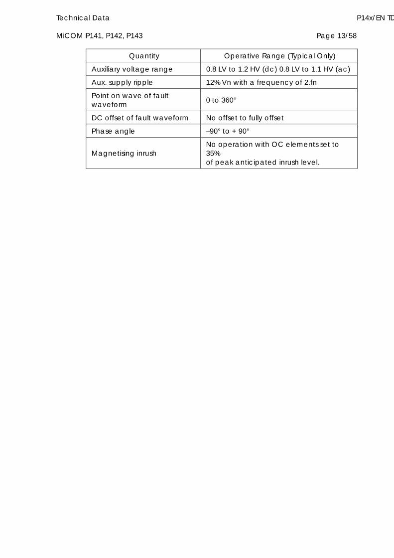
Technical Data P14x/EN TD MiCOM P141, P142, P143 Page 13/58
Operative Range (Typical Only) Quantity
Auxiliary voltage range 0.8 LV to 1.2 HV (dc) 0.8 LV to 1.1 HV (ac)
Aux. supply ripple 12% Vn with a frequency of 2.fn
Point on wave of fault waveform 0 to 360°
DC offset of fault waveform No offset to fully offset
Phase angle –90° to + 90°
Magnetising inrush No operation with OC elements set to 35% of peak anticipated inrush level.
P14x/EN TD/B54 Technical Data Page 14/58 MiCOM P141, P142, P143
4. HIGH VOLTAGE WITHSTAND
4.1 Dielectric withstand IEC60255-5: 2000
2.0kVrms for one minute between all terminals and case earth.
2.0kVrms for one minute between all terminals of each independent circuit grouped together, and all other terminals. This includes the output contacts and loop through connections D17/D18.
1.5kVrms for one minute across dedicated normally open contacts of output relays.
1.0kVrms for 1 minute across normally open contacts of changeover and watchdog output relays.
1.0kVrms for 1 minute for all D-type connections between line and ground.
4.2 Impulse IEC60255-5:1997
The product will withstand without damage impulses of 5kV peak, 1.2/50µs, 0.5J across:
Each independent circuit and the case with the terminals of each independent circuit connected together.
Independent circuits with the terminals of each independent circuit connected together.
Terminals of the same circuit except normally open metallic contacts.
4.3 Insulation resistance IEC60255-5:1997
The insulation resistance is greater than 100 Mat 500Vdc.
4.4 ANSI dielectric withstand ANSI/IEEE C37.90. (1989) (Reaff. 1994)
1kV rms. for 1 minute across open contacts of the watchdog contacts.
1kV rms. for 1 minute across open contacts of changeover output contacts.
1.5kV rms. for 1 minute across normally open output contacts.

Technical Data P14x/EN TD MiCOM P141, P142, P143 Page 15/58
5. ELECTRICAL ENVIRONMENT
5.1 Performance criteria The following three classes of performance criteria are used within sections 4.2 to 4.12 (where applicable) to specify the performance of the MiCOM relay when subjected to the electrical interference. The performance criteria are based on the performance criteria specified in EN 50082-2:1995.
5.1.1 Class A
During the testing the relay will not maloperate, upon completion of the testing the relay will function as specified. A maloperation will include a transient operation of the output contacts, operation of the watchdog contacts, reset of any of the relays microprocessors or an alarm indication.
The relay communications and IRIG-B signal must continue uncorrupted via the communications ports and IRIG-B port respectively during the test, however relay communications and the IRIG-B signal may be momentarily interrupted during the tests, provided that they recover with no external intervention.
5.1.2 Class B
During the testing the relay will not maloperate, upon completion of the testing the relay will function as specified. A maloperation will include a transient operation of the output contacts, operation of the watchdog contacts, reset of any of the relays microprocessors or an alarm indication. A transitory operation of the output LEDs is acceptable provided no permanent false indications are recorded.
The relay communications and IRIG-B signal must continue uncorrupted via the communications ports and IRIG-B port respectively during the test, however relay communications and the IRIG-B signal may be momentarily interrupted during the tests, provided that they recover with no external intervention.
5.1.3 Class C
The relay will power down and power up again in a controlled manner within 5 seconds. The output relays are permitted to change state during the test as long as they reset once the relay powers up.
Communications to relay may be suspended during the testing as long as communication recovers with no external intervention after the testing.
5.2 Auxiliary supply tests, dc interruption, etc. 5.2.1 DC voltage interruptions
IEC 60255-11:1979.
DC Auxiliary Supply Interruptions 2, 5, 10, 20ms.
Performance criteria - Class A.
DC Auxiliary Supply Interruptions 50, 100, 200ms, 40s.
Performance criteria - Class C.
P14x/EN TD/B54 Technical Data Page 16/58 MiCOM P141, P142, P143
5.2.2 DC voltage fluctuations
IEC 60255-11:1979.
AC 100Hz ripple superimposed on DC max. and min. auxiliary supply at 12% of highest rated DC.
Performance criteria - Class A.
5.3 AC voltage dips and short interruptions 5.3.1 AC voltage short interruptions
IEC 61000-4-11:1994.
AC Auxiliary Supply Interruptions 2, 5, 10, 20ms.
Performance criteria - Class A.
AC Auxiliary Supply Interruptions 50, 100, 200ms, 1s, 40s.
Performance criteria - Class C.
5.3.2 AC voltage dips
IEC 61000-4-11:1994
AC Auxiliary Supply 100% Voltage Dips 2, 5, 10, 20ms.
Performance criteria –Class A.
AC Auxiliary Supply 100% Voltage Dips 50, 100, 200ms, 1s, 40s.
Performance criteria - Class C.
AC Auxiliary Supply 60% Voltage Dips 2, 5, 10, 20ms.
Performance criteria - Class A.
AC Auxiliary Supply 60% Voltage Dips 50, 100, 200ms, 1s, 40s.
Performance criteria - Class C.
AC Auxiliary Supply 30% Voltage Dips 2, 5, 10, 20ms.
Performance criteria - Class A.
AC Auxiliary Supply 30% Voltage Dips 50, 100, 200ms, 1s, 40s.
Performance criteria - Class C.
5.4 High frequency disturbance IEC 60255-22-1:1988 Class III.
1MHz burst disturbance test.
2.5kV common mode.
Power supply, field voltage, CTs, VTs, opto inputs, output contacts, IRIG-B and terminal block communications connections.
1kV differential mode.
Power supply, field voltage, CTs, VTs, opto inputs and output contacts.
Technical Data P14x/EN TD MiCOM P141, P142, P143 Page 17/58
Performance criteria Class A.
5.5 Fast transients IEC 60255-22-4:1992 (EN 61000-4-4:1995), Class III and Class IV.
2kV 5kHz (Class III) and 4kV 2.5kHz (Class IV) direct coupling.
Power supply, field voltage, opto inputs, output contacts, CTs, VTs.
2kV 5kHz (Class III) and 4kV 2.5kHz (Class IV) capacitive clamp.
IRIG-B and terminal block communications connections.
Performance criteria Class A.
5.6 Conducted/radiated emissions 5.6.1 Conducted emissions
EN 55011:1998 Class A, EN 55022:1994 Class A.
0.15 - 0.5MHz, 79dBV (quasi peak) 66dBV (average).
0.5 - 30MHz, 73dBV (quasi peak) 60dBV (average).
5.6.2 Radiated emissions
EN 55011:1998 Class A, EN 55022:1994 Class A.
30 - 230MHz, 40dBV/m at 10m measurement distance. 230 - 1000MHz, 47dBV/m at 10m measurement distance.
5.7 Conducted/radiated immunity 5.7.1 Conducted immunity
EN 61000-4-6:1996 Level 3.
10V emf @ 1kHz 80% am, 150kHz to 80MHz. Spot tests at 27MHz, 68MHz.
Performance criteria Class A.
5.7.2 Radiated immunity
IEC 60255-22-3:1989 Class III (EN 61000-4-3: 1997 Level 3).
10 V/m 80MHz - 1GHz @ 1kHz 80% am.
Spot tests at 80MHz, 160MHz, 450MHz, 900MHz.
Performance criteria Class A.
5.7.3 Radiated immunity from digital radio telephones
ENV 50204:1995
10 V/m 900MHz 5 MHz and 1.89GHz 5MHz, 200Hz rep. Freq., 50% duty cycle pulse modulated.
Performance criteria Class A.
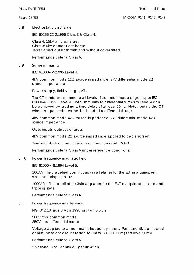
P14x/EN TD/B54 Technical Data Page 18/58 MiCOM P141, P142, P143
5.8 Electrostatic discharge IEC 60255-22-2:1996 Class 3 & Class 4.
Class 4: 15kV air discharge. Class 3: 6kV contact discharge. Tests carried out both with and without cover fitted.
Performance criteria Class A.
5.9 Surge immunity IEC 61000-4-5:1995 Level 4.
4kV common mode 12 source impedance, 2kV differential mode 2 source impedance.
Power supply, field voltage, VTs.
The CT inputs are immune to all levels of common mode surge as per IEC 61000-4-5: 1995 Level 4. Total immunity to differential surges to Level 4 can be achieved by adding a time delay of at least 20ms. Note, routing the CT wires as a pair reduces the likelihood of a differential surge.
4kV common mode 42 source impedance, 2kV differential mode 42 source impedance.
Opto inputs, output contacts.
4kV common mode 2 source impedance applied to cable screen.
Terminal block communications connections and IRIG-B.
Performance criteria Class A under reference conditions.
5.10 Power frequency magnetic field IEC 61000-4-8:1994 Level 5.
100A/m field applied continuously in all planes for the EUT in a quiescent state and tripping state
1000A/m field applied for 3s in all planes for the EUT in a quiescent state and tripping state
Performance criteria Class A.
5.11 Power frequency interference NGTS* 2.13 Issue 3 April 1998, section 5.5.6.9.
500V rms. common mode. 250V rms. differential mode.
Voltage applied to all non-mains frequency inputs. Permanently connected communications circuits tested to Class 3 (100-1000m) test level 50mV
Performance criteria Class A.
* National Grid Technical Specification
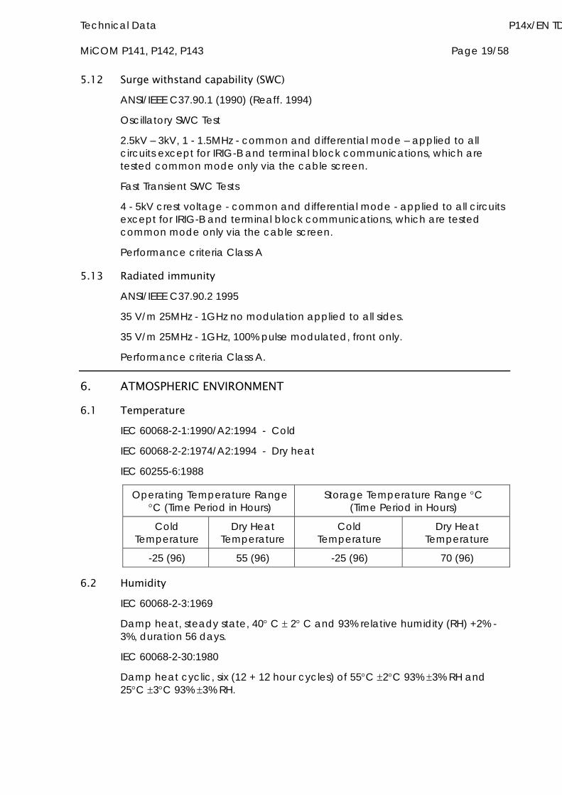
Technical Data P14x/EN TD MiCOM P141, P142, P143 Page 19/58
5.12 Surge withstand capability (SWC) ANSI/IEEE C37.90.1 (1990) (Reaff. 1994)
Oscillatory SWC Test
2.5kV – 3kV, 1 - 1.5MHz - common and differential mode – applied to all circuits except for IRIG-B and terminal block communications, which are tested common mode only via the cable screen.
Fast Transient SWC Tests
4 - 5kV crest voltage - common and differential mode - applied to all circuits except for IRIG-B and terminal block communications, which are tested common mode only via the cable screen.
Performance criteria Class A
5.13 Radiated immunity ANSI/IEEE C37.90.2 1995
35 V/m 25MHz - 1GHz no modulation applied to all sides.
35 V/m 25MHz - 1GHz, 100% pulse modulated, front only.
Performance criteria Class A.
6. ATMOSPHERIC ENVIRONMENT
6.1 Temperature IEC 60068-2-1:1990/A2:1994 - Cold
IEC 60068-2-2:1974/A2:1994 - Dry heat
IEC 60255-6:1988
Operating Temperature Range C (Time Period in Hours)
Storage Temperature Range C (Time Period in Hours)
Cold Temperature
Dry Heat Temperature
Cold Temperature
Dry Heat Temperature
-25 (96) 55 (96) -25 (96) 70 (96)
6.2 Humidity IEC 60068-2-3:1969
Damp heat, steady state, 40 C 2 C and 93% relative humidity (RH) +2% -3%, duration 56 days.
IEC 60068-2-30:1980
Damp heat cyclic, six (12 + 12 hour cycles) of 55C 2C 93% 3% RH and 25C 3C 93% 3% RH.

P14x/EN TD/B54 Technical Data Page 20/58 MiCOM P141, P142, P143
6.3 Enclosure protection IEC 60529:1989
IP52 Category 2
IP5x – Protected against dust, limited ingress permitted.
IPx2 – Protected against vertically falling drops of water with the product in 4 fixed positions of 15 tilt with a flow rate of 3mm/minute for 2.5 minutes.
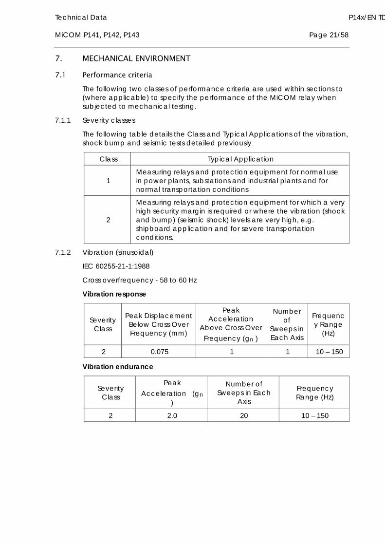
Technical Data P14x/EN TD MiCOM P141, P142, P143 Page 21/58
7. MECHANICAL ENVIRONMENT
7.1 Performance criteria The following two classes of performance criteria are used within sections to (where applicable) to specify the performance of the MiCOM relay when subjected to mechanical testing.
7.1.1 Severity classes
The following table details the Class and Typical Applications of the vibration, shock bump and seismic tests detailed previously
Class Typical Application
1 Measuring relays and protection equipment for normal use in power plants, substations and industrial plants and for normal transportation conditions
2
Measuring relays and protection equipment for which a very high security margin is required or where the vibration (shock and bump) (seismic shock) levels are very high, e.g. shipboard application and for severe transportation conditions.
7.1.2 Vibration (sinusoidal)
IEC 60255-21-1:1988
Cross overfrequency - 58 to 60 Hz
Vibration response
Severity Class
Peak Displacement Below Cross Over Frequency (mm)
Peak Acceleration
Above Cross Over Frequency (gn )
Number of
Sweeps in Each Axis
Frequency Range
(Hz)
2 0.075 1 1 10 – 150
Vibration endurance
Severity Class
Peak Acceleration (gn
)
Number of Sweeps in Each
Axis
Frequency Range (Hz)
2 2.0 20 10 – 150
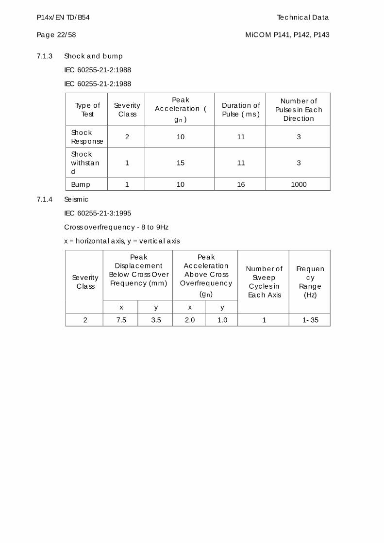
P14x/EN TD/B54 Technical Data Page 22/58 MiCOM P141, P142, P143
7.1.3 Shock and bump
IEC 60255-21-2:1988
IEC 60255-21-2:1988
Type of Test
Severity Class
Peak Acceleration (
gn )
Duration of Pulse ( ms )
Number of Pulses in Each
Direction
Shock Response 2 10 11 3
Shock withstand
1 15 11 3
Bump 1 10 16 1000
7.1.4 Seismic
IEC 60255-21-3:1995
Cross overfrequency - 8 to 9Hz
x = horizontal axis, y = vertical axis
Peak Displacement
Below Cross Over Frequency (mm)
Peak Acceleration Above Cross
Overfrequency (gn)
Severity Class
x y x y
Number of Sweep
Cycles in Each Axis
Frequency
Range (Hz)
2 7.5 3.5 2.0 1.0 1 1- 35
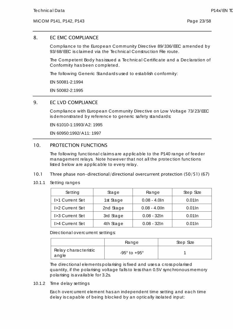
Technical Data P14x/EN TD MiCOM P141, P142, P143 Page 23/58
8. EC EMC COMPLIANCE Compliance to the European Community Directive 89/336/EEC amended by 93/68/EEC is claimed via the Technical Construction File route.
The Competent Body has issued a Technical Certificate and a Declaration of Conformity has been completed.
The following Generic Standards used to establish conformity:
EN 50081-2:1994
EN 50082-2:1995
9. EC LVD COMPLIANCE Compliance with European Community Directive on Low Voltage 73/23/EEC is demonstrated by reference to generic safety standards:
EN 61010-1:1993/A2: 1995
EN 60950:1992/A11: 1997
10. PROTECTION FUNCTIONS The following functional claims are applicable to the P140 range of feeder management relays. Note however that not all the protection functions listed below are applicable to every relay.
10.1 Three phase non-directional/directional overcurrent protection (50/51) (67) 10.1.1 Setting ranges
Setting Stage Range Step Size
>1 Current Set 1st Stage 0.08 - 4.0n 0.01n
>2 Current Set 2nd Stage 0.08 - 4.0In 0.01n
>3 Current Set 3rd Stage 0.08 - 32n 0.01n
>4 Current Set 4th Stage 0.08 - 32n 0.01n
Directional overcurrent settings:
Range Step Size
Relay characteristic angle -95° to +95° 1
The directional elements polarising is fixed and uses a cross polarised quantity, if the polarising voltage falls to less than 0.5V synchronous memory polarising is available for 3.2s.
10.1.2 Time delay settings
Each overcurrent element has an independent time setting and each time delay is capable of being blocked by an optically isolated input:
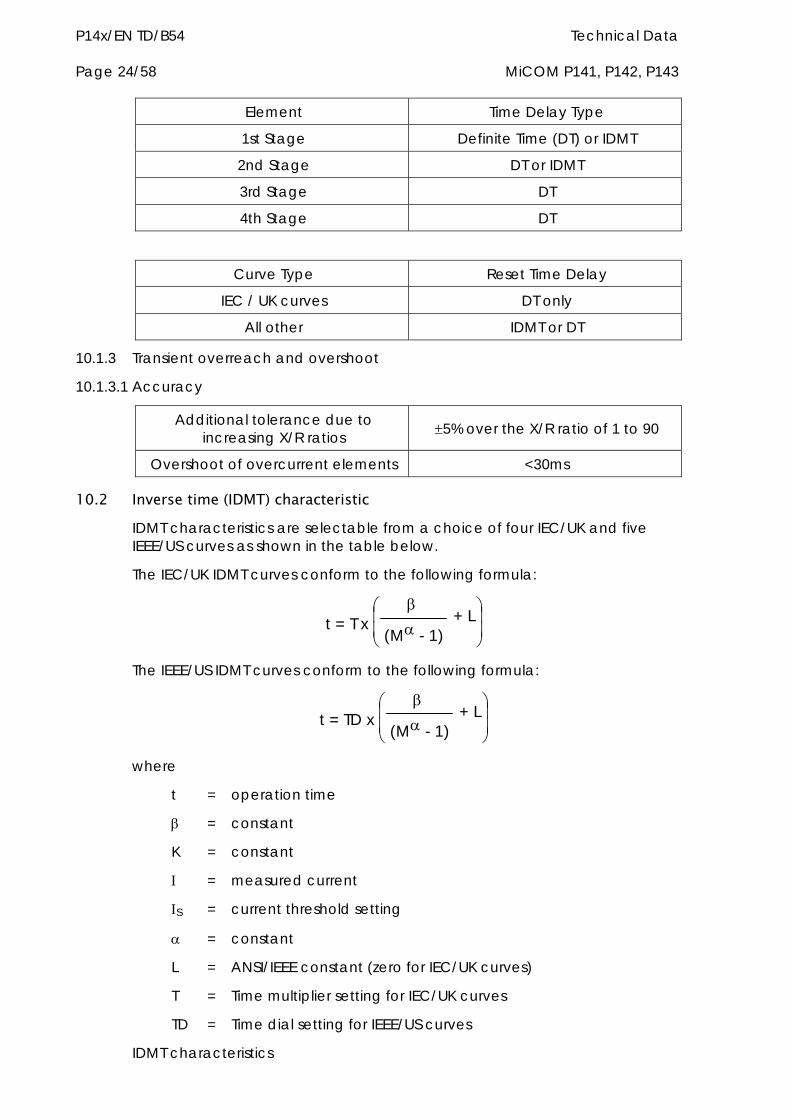
P14x/EN TD/B54 Technical Data Page 24/58 MiCOM P141, P142, P143
Element Time Delay Type
1st Stage Definite Time (DT) or IDMT
2nd Stage DT or IDMT
3rd Stage DT
4th Stage DT
Curve Type Reset Time Delay
IEC / UK curves DT only
All other IDMT or DT
10.1.3 Transient overreach and overshoot
10.1.3.1 Accuracy
Additional tolerance due to increasing X/R ratios 5% over the X/R ratio of 1 to 90
Overshoot of overcurrent elements <30ms
10.2 Inverse time (IDMT) characteristic IDMT characteristics are selectable from a choice of four IEC/UK and five IEEE/US curves as shown in the table below.
The IEC/UK IDMT curves conform to the following formula:
t = T x
(M - 1) + L
The IEEE/US IDMT curves conform to the following formula:
t = TD x
(M - 1) + L
where
t = operation time
= constant
K = constant
= measured current
S = current threshold setting
= constant
L = ANSI/IEEE constant (zero for IEC/UK curves)
T = Time multiplier setting for IEC/UK curves
TD = Time dial setting for IEEE/US curves
IDMT characteristics
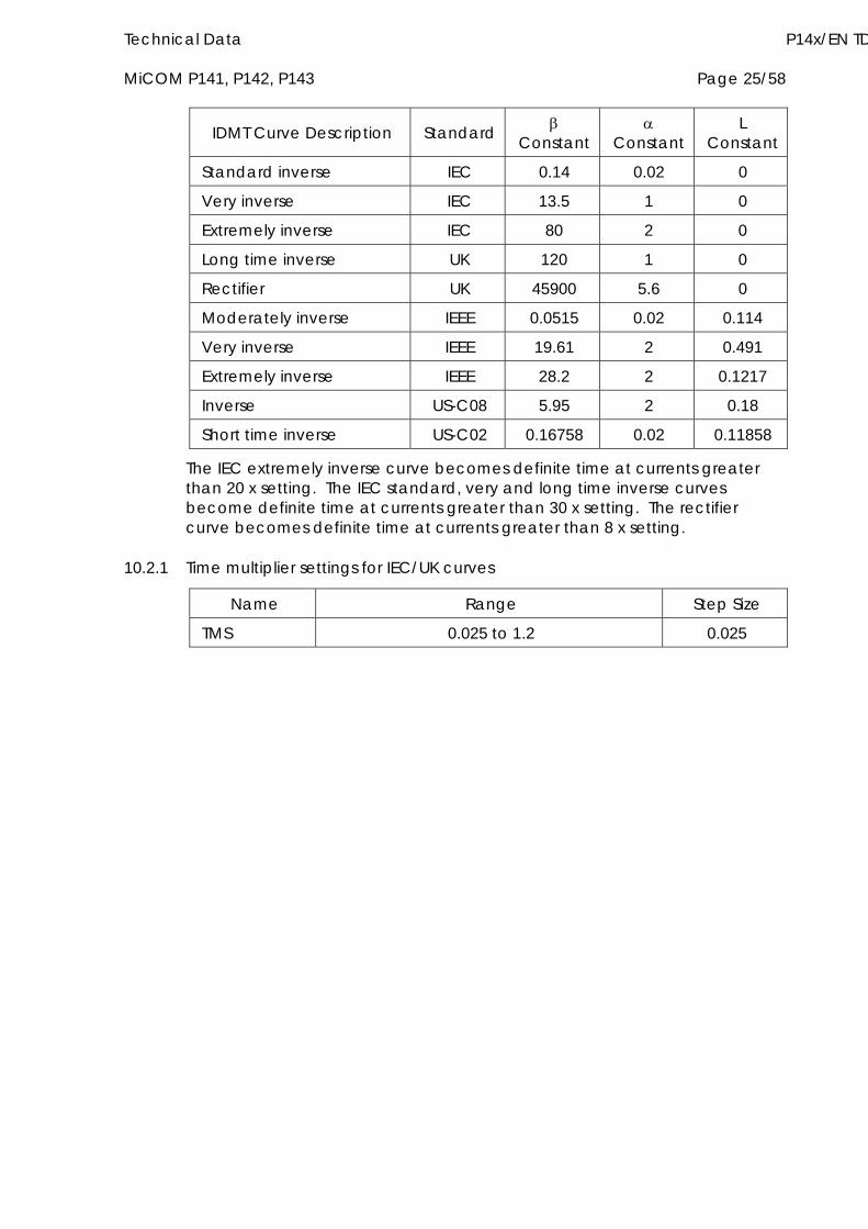
Technical Data P14x/EN TD MiCOM P141, P142, P143 Page 25/58
IDMT Curve Description Standard Constant
Constant
L Constant
Standard inverse IEC 0.14 0.02 0
Very inverse IEC 13.5 1 0
Extremely inverse IEC 80 2 0
Long time inverse UK 120 1 0
Rectifier UK 45900 5.6 0
Moderately inverse IEEE 0.0515 0.02 0.114
Very inverse IEEE 19.61 2 0.491
Extremely inverse IEEE 28.2 2 0.1217
Inverse US-C08 5.95 2 0.18
Short time inverse US-C02 0.16758 0.02 0.11858
The IEC extremely inverse curve becomes definite time at currents greater than 20 x setting. The IEC standard, very and long time inverse curves become definite time at currents greater than 30 x setting. The rectifier curve becomes definite time at currents greater than 8 x setting.
10.2.1 Time multiplier settings for IEC/UK curves
Name Range Step Size
TMS 0.025 to 1.2 0.025
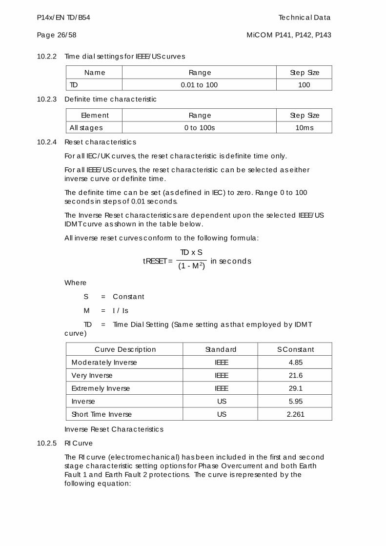
P14x/EN TD/B54 Technical Data Page 26/58 MiCOM P141, P142, P143
10.2.2 Time dial settings for IEEE/US curves
Name Range Step Size
TD 0.01 to 100 100
10.2.3 Definite time characteristic
Element Range Step Size
All stages 0 to 100s 10ms
10.2.4 Reset characteristics
For all IEC/UK curves, the reset characteristic is definite time only.
For all IEEE/US curves, the reset characteristic can be selected as either inverse curve or definite time.
The definite time can be set (as defined in IEC) to zero. Range 0 to 100 seconds in steps of 0.01 seconds.
The Inverse Reset characteristics are dependent upon the selected IEEE/US IDMT curve as shown in the table below.
All inverse reset curves conform to the following formula:
tRESET = TD x S
(1 - M2) in seconds
Where
S = Constant
M = / s
TD = Time Dial Setting (Same setting as that employed by IDMT curve)
Curve Description Standard S Constant
Moderately Inverse IEEE 4.85
Very Inverse IEEE 21.6
Extremely Inverse IEEE 29.1
Inverse US 5.95
Short Time Inverse US 2.261
Inverse Reset Characteristics
10.2.5 RI Curve
The RI curve (electromechanical) has been included in the first and second stage characteristic setting options for Phase Overcurrent and both Earth Fault 1 and Earth Fault 2 protections. The curve is represented by the following equation:
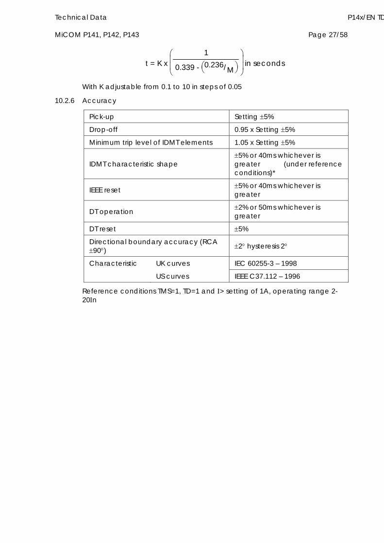
Technical Data P14x/EN TD MiCOM P141, P142, P143 Page 27/58
t = K x
1
0.339 - 0.236/M
in seconds
With K adjustable from 0.1 to 10 in steps of 0.05
10.2.6 Accuracy
Pick-up Setting 5%
Drop-off 0.95 x Setting 5%
Minimum trip level of IDMT elements 1.05 x Setting 5%
IDMT characteristic shape 5% or 40ms whichever is greater (under reference conditions)*
IEEE reset 5% or 40ms whichever is greater
DT operation 2% or 50ms whichever is greater
DT reset 5%
Directional boundary accuracy (RCA 90) 2 hysteresis 2
Characteristic UK curves IEC 60255-3 – 1998
US curves IEEE C37.112 – 1996
Reference conditions TMS=1, TD=1 and > setting of 1A, operating range 2-20n
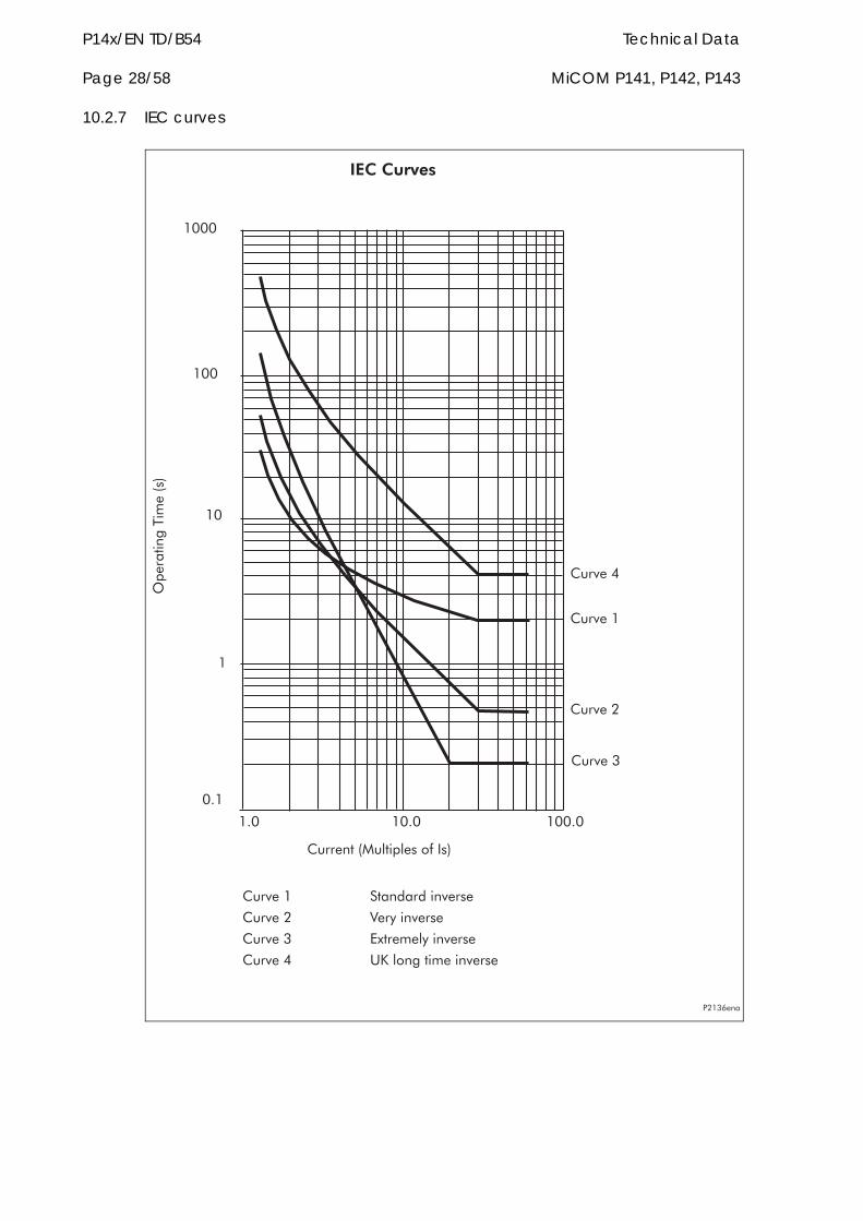
P14x/EN TD/B54 Technical Data Page 28/58 MiCOM P141, P142, P143
10.2.7 IEC curves
�������
������
������
�������
���
��
�
�
�� �� � �
�������������������������
������������������
������ ���� �� ��������
������ !��"��������
������� #$������"��������
������� %&������������������
��������
' � �� ( �
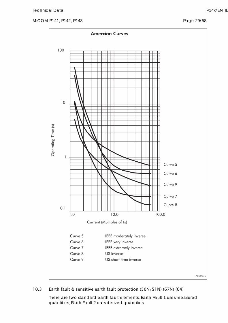
Technical Data P14x/EN TD MiCOM P141, P142, P143 Page 29/58
������) �###��� ������"��������
������( �###����"��������
������* �###��$������"��������
������+ %���������
������, %���-����������������
��� ��������
������)
�� �� � �
�������������������������
�
�
��������������������
������(
������,
������*
������+
'�*���
10.3 Earth fault & sensitive earth fault protection (50N/51N) (67N) (64) There are two standard earth fault elements, Earth Fault 1 uses measured quantities, Earth Fault 2 uses derived quantities.
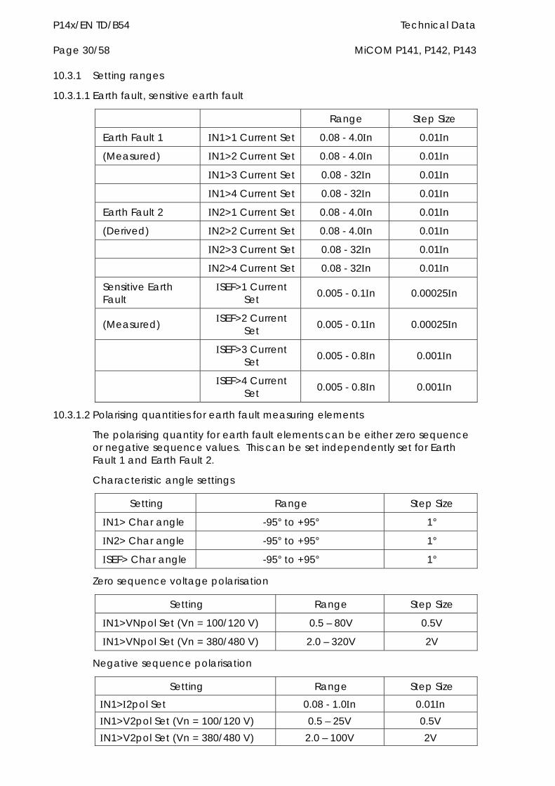
P14x/EN TD/B54 Technical Data Page 30/58 MiCOM P141, P142, P143
10.3.1 Setting ranges
10.3.1.1 Earth fault, sensitive earth fault
Range Step Size
Earth Fault 1 N1>1 Current Set 0.08 - 4.0n 0.01n
(Measured) N1>2 Current Set 0.08 - 4.0n 0.01n
N1>3 Current Set 0.08 - 32n 0.01n
N1>4 Current Set 0.08 - 32n 0.01n
Earth Fault 2 N2>1 Current Set 0.08 - 4.0n 0.01n
(Derived) N2>2 Current Set 0.08 - 4.0n 0.01n
N2>3 Current Set 0.08 - 32n 0.01n
N2>4 Current Set 0.08 - 32n 0.01n
Sensitive Earth Fault
SEF>1 Current Set 0.005 - 0.1n 0.00025n
(Measured) SEF>2 Current Set 0.005 - 0.1n 0.00025n
SEF>3 Current Set 0.005 - 0.8n 0.001n
SEF>4 Current Set 0.005 - 0.8n 0.001n
10.3.1.2 Polarising quantities for earth fault measuring elements
The polarising quantity for earth fault elements can be either zero sequence or negative sequence values. This can be set independently set for Earth Fault 1 and Earth Fault 2.
Characteristic angle settings
Setting Range Step Size
N1> Char angle -95° to +95° 1°
N2> Char angle -95° to +95° 1°
SEF> Char angle -95° to +95° 1°
Zero sequence voltage polarisation
Setting Range Step Size
N1>VNpol Set (Vn = 100/120 V) 0.5 – 80V 0.5V
N1>VNpol Set (Vn = 380/480 V) 2.0 – 320V 2V
Negative sequence polarisation
Setting Range Step Size
N1>2pol Set 0.08 - 1.0n 0.01n N1>V2pol Set (Vn = 100/120 V) 0.5 – 25V 0.5V N1>V2pol Set (Vn = 380/480 V) 2.0 – 100V 2V
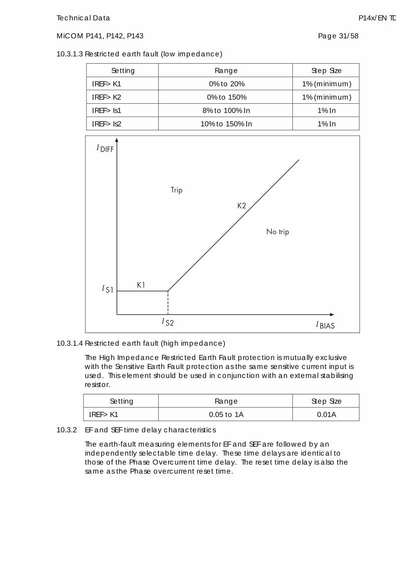
Technical Data P14x/EN TD MiCOM P141, P142, P143 Page 31/58
10.3.1.3 Restricted earth fault (low impedance)
Setting Range Step Size
REF> K1 0% to 20% 1% (minimum)
REF> K2 0% to 150% 1% (minimum)
REF> Is1 8% to 100% n 1% n
REF> Is2 10% to 150% n 1% n
�����
��� ��
��
������
�� �
����� �
10.3.1.4 Restricted earth fault (high impedance)
The High Impedance Restricted Earth Fault protection is mutually exclusive with the Sensitive Earth Fault protection as the same sensitive current input is used. This element should be used in conjunction with an external stabilising resistor.
Setting Range Step Size
REF> K1 0.05 to 1A 0.01A
10.3.2 EF and SEF time delay characteristics
The earth-fault measuring elements for EF and SEF are followed by an independently selectable time delay. These time delays are identical to those of the Phase Overcurrent time delay. The reset time delay is also the same as the Phase overcurrent reset time.
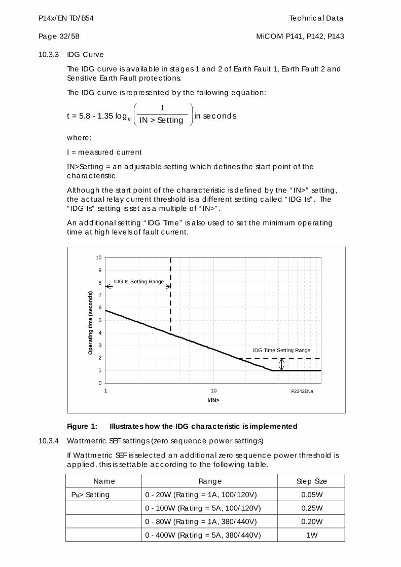
P14x/EN TD/B54 Technical Data Page 32/58 MiCOM P141, P142, P143
10.3.3 IDG Curve
The IDG curve is available in stages 1 and 2 of Earth Fault 1, Earth Fault 2 and Sensitive Earth Fault protections.
The IDG curve is represented by the following equation:
t = 5.8 - 1.35 loge
N > Setting in seconds
where:
= measured current
N>Setting = an adjustable setting which defines the start point of the characteristic
Although the start point of the characteristic is defined by the “N>” setting, the actual relay current threshold is a different setting called “IDG s”. The “IDG s” setting is set as a multiple of “N>”.
An additional setting “IDG Time” is also used to set the minimum operating time at high levels of fault current.
0
1
2
3
4
5
6
7
8
9
10
1 10
I/IN>
Op
erat
ing
tim
e (
seco
nd
s)
100
IDG Is Setting Range
IDG Time Setting Range
Figure 1: Illustrates how the IDG characteristic is implemented
10.3.4 Wattmetric SEF settings (zero sequence power settings)
If Wattmetric SEF is selected an additional zero sequence power threshold is applied, this is settable according to the following table.
Name Range Step Size
PN> Setting 0 - 20W (Rating = 1A, 100/120V) 0.05W
0 - 100W (Rating = 5A, 100/120V) 0.25W
0 - 80W (Rating = 1A, 380/440V) 0.20W
0 - 400W (Rating = 5A, 380/440V) 1W
P2242ENa
Technical Data P14x/EN TD MiCOM P141, P142, P143 Page 33/58
10.3.5 Accuracy
10.3.5.1 Earth fault 1
Pick-up For DT Start Setting 5%
Drop-off For IDMT Start 0.95 x Setting 5%
Minimum trip level of IDMT elements 1.05 x Setting 5%
IDMT characteristic shape 5% or 40ms whichever is greater (under reference conditions)*
IEEE reset 5% or 40ms whichever is greater
DT operation 2% or 50ms whichever is greater
DT reset 5%
Repeatability 2.5%
* Reference conditions TMS=1, TD=1 and N> setting of 1A, operating range 2-20n
10.3.5.2 Earth fault 2
Pick-up For DT Start Setting 5%
Drop-off For IDMT Start 0.95 x Setting 5%
Minimum trip level of IDMT elements 1.05 x Setting 5%
IDMT characteristic shape 5% or 40ms whichever is greater (under reference conditions)*
IEEE reset 10% or 40ms whichever is greater
DT operation 2% or 50ms whichever is greater
DT reset 2% or 50ms whichever is greater
Repeatability 5%
* Reference conditions TMS=1, TD=1 and N> setting of 1A, operating range 2-20n
10.3.5.3 SEF
Pick-up For DT Start Setting 5%
Drop-off For IDMT Start 0.95 x Setting 5%
Minimum trip level of IDMT elements 1.05 x Setting 5%
IDMT characteristic shape 5% or 40ms whichever is greater (under reference conditions)*
IEEE reset 7.5% or 60ms whichever is greater
DT operation 2% or 50ms whichever is greater
DT reset 5%
Repeatability 5%
* Reference conditions TMS=1, TD=1 and N> setting of 100mA, operating range 2-20s
P14x/EN TD/B54 Technical Data Page 34/58 MiCOM P141, P142, P143
10.3.5.4 REF
Pick-up Setting formula 5%
Drop-off 0.80 x Setting formula 5%
Low impedance operating time <60ms
High impedance pick-up Setting 5%
High impedance operating time <30ms
Repeatability <15%
10.3.5.5 Wattmetric SEF
For P=0W SEF> 5% Pick-up
For P>0W P> 5%
For P=0W (0.95 x SEF>) 5% Drop-off
For P>0W 0.9 x P> 5%
Boundary accuracy 5% with 1 hysteresis
Repeatability 5%
10.3.5.6 Polarising quantities
Zero sequence polarising
Operating boundary pick-up 2of RCA 90
Hysteresis <3
VN> Pick-up Setting 10%
VN> Drop-off 0.9 x Setting 10%
Negative sequence polarising
Operating boundary pick-up 2of RCA 90
Hysteresis <3
V2> Pick-up Setting 10%
V2> Drop-off 0.9 x Setting 10%
2> Pick-up Setting 10%
2> Drop-off 0.9 x Setting 10%
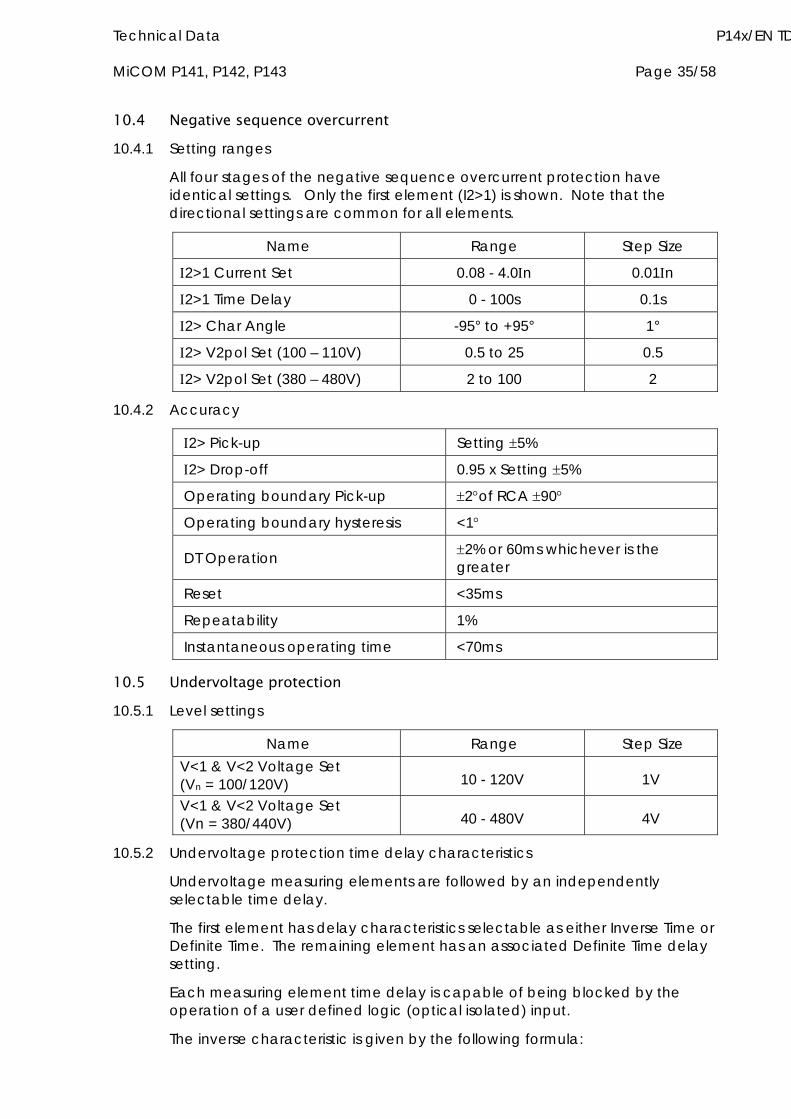
Technical Data P14x/EN TD MiCOM P141, P142, P143 Page 35/58
10.4 Negative sequence overcurrent 10.4.1 Setting ranges
All four stages of the negative sequence overcurrent protection have identical settings. Only the first element (I2>1) is shown. Note that the directional settings are common for all elements.
Name Range Step Size
2>1 Current Set 0.08 - 4.0n 0.01n
2>1 Time Delay 0 - 100s 0.1s
2> Char Angle -95° to +95° 1°
2> V2pol Set (100 – 110V) 0.5 to 25 0.5
2> V2pol Set (380 – 480V) 2 to 100 2
10.4.2 Accuracy
2> Pick-up Setting 5%
2> Drop-off 0.95 x Setting 5%
Operating boundary Pick-up 2of RCA 90
Operating boundary hysteresis <1
DT Operation 2% or 60ms whichever is the greater
Reset <35ms
Repeatability 1%
Instantaneous operating time <70ms
10.5 Undervoltage protection 10.5.1 Level settings
Name Range Step Size V<1 & V<2 Voltage Set (Vn = 100/120V) 10 - 120V 1V
V<1 & V<2 Voltage Set (Vn = 380/440V) 40 - 480V 4V
10.5.2 Undervoltage protection time delay characteristics
Undervoltage measuring elements are followed by an independently selectable time delay.
The first element has delay characteristics selectable as either Inverse Time or Definite Time. The remaining element has an associated Definite Time delay setting.
Each measuring element time delay is capable of being blocked by the operation of a user defined logic (optical isolated) input.
The inverse characteristic is given by the following formula:
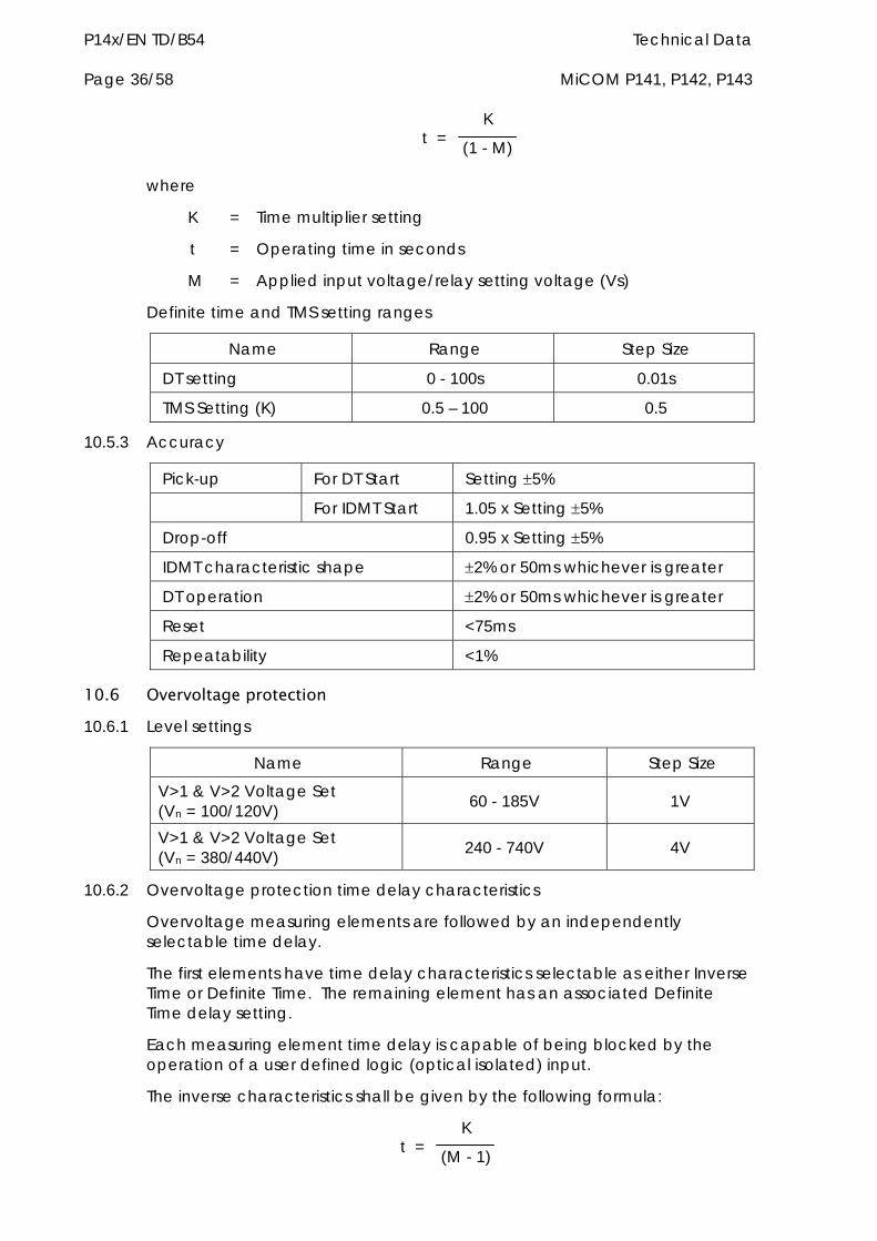
P14x/EN TD/B54 Technical Data Page 36/58 MiCOM P141, P142, P143
t = K
(1 - M)
where
K = Time multiplier setting
t = Operating time in seconds
M = Applied input voltage/relay setting voltage (Vs)
Definite time and TMS setting ranges
Name Range Step Size
DT setting 0 - 100s 0.01s
TMS Setting (K) 0.5 – 100 0.5
10.5.3 Accuracy
Pick-up For DT Start Setting 5%
For IDMT Start 1.05 x Setting 5%
Drop-off 0.95 x Setting 5%
IDMT characteristic shape 2% or 50ms whichever is greater
DT operation 2% or 50ms whichever is greater
Reset <75ms
Repeatability <1%
10.6 Overvoltage protection 10.6.1 Level settings
Name Range Step Size
V>1 & V>2 Voltage Set (Vn = 100/120V) 60 - 185V 1V
V>1 & V>2 Voltage Set (Vn = 380/440V) 240 - 740V 4V
10.6.2 Overvoltage protection time delay characteristics
Overvoltage measuring elements are followed by an independently selectable time delay.
The first elements have time delay characteristics selectable as either Inverse Time or Definite Time. The remaining element has an associated Definite Time delay setting.
Each measuring element time delay is capable of being blocked by the operation of a user defined logic (optical isolated) input.
The inverse characteristics shall be given by the following formula:
t = K
(M - 1)
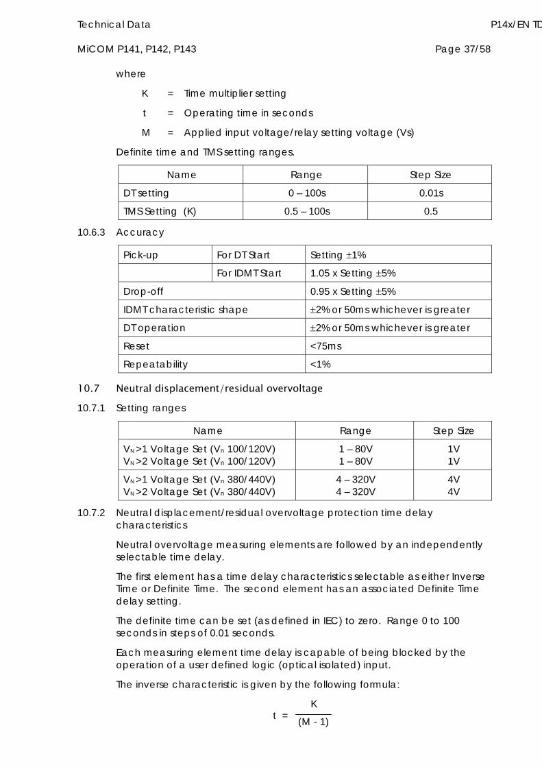
Technical Data P14x/EN TD MiCOM P141, P142, P143 Page 37/58
where
K = Time multiplier setting
t = Operating time in seconds
M = Applied input voltage/relay setting voltage (Vs)
Definite time and TMS setting ranges.
Name Range Step Size
DT setting 0 – 100s 0.01s
TMS Setting (K) 0.5 – 100s 0.5
10.6.3 Accuracy
Pick-up For DT Start Setting 1%
For IDMT Start 1.05 x Setting 5%
Drop-off 0.95 x Setting 5%
IDMT characteristic shape 2% or 50ms whichever is greater
DT operation 2% or 50ms whichever is greater
Reset <75ms
Repeatability <1%
10.7 Neutral displacement/residual overvoltage 10.7.1 Setting ranges
Name Range Step Size
VN >1 Voltage Set (Vn 100/120V) VN >2 Voltage Set (Vn 100/120V)
1 – 80V 1 – 80V
1V 1V
VN >1 Voltage Set (Vn 380/440V) VN >2 Voltage Set (Vn 380/440V)
4 – 320V 4 – 320V
4V 4V
10.7.2 Neutral displacement/residual overvoltage protection time delay characteristics
Neutral overvoltage measuring elements are followed by an independently selectable time delay.
The first element has a time delay characteristics selectable as either Inverse Time or Definite Time. The second element has an associated Definite Time delay setting.
The definite time can be set (as defined in IEC) to zero. Range 0 to 100 seconds in steps of 0.01 seconds.
Each measuring element time delay is capable of being blocked by the operation of a user defined logic (optical isolated) input.
The inverse characteristic is given by the following formula:
t = K
(M - 1)
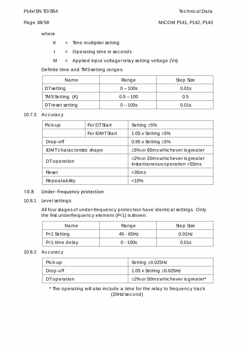
P14x/EN TD/B54 Technical Data Page 38/58 MiCOM P141, P142, P143
where
K = Time multiplier setting
t = Operating time in seconds
M = Applied input voltage/relay setting voltage (Vs)
Definite time and TMS setting ranges.
Name Range Step Size
DT setting 0 – 100s 0.01s
TMS Setting (K) 0.5 – 100 0.5
DT reset setting 0 – 100s 0.01s
10.7.3 Accuracy
Pick-up For DT Start Setting 5%
For IDMT Start 1.05 x Setting 5%
Drop-off 0.95 x Setting 5%
IDMT characteristic shape 5% or 65ms whichever is greater
DT operation 2% or 20ms whichever is greater Instantaneous operation <55ms
Reset <35ms
Repeatability <10%
10.8 Under-frequency protection 10.8.1 Level settings
All four stages of under-frequency protection have identical settings. Only the first underfrequency element (F<1) is shown.
Name Range Step Size
F<1 Setting 45 - 65Hz 0.01Hz
F<1 time delay 0 - 100s 0.01s
10.8.2 Accuracy
Pick-up Setting 0.025Hz
Drop-off 1.05 x Setting 0.025Hz
DT operation 2% or 50ms whichever is greater*
* The operating will also include a time for the relay to frequency track (20Hz/second)
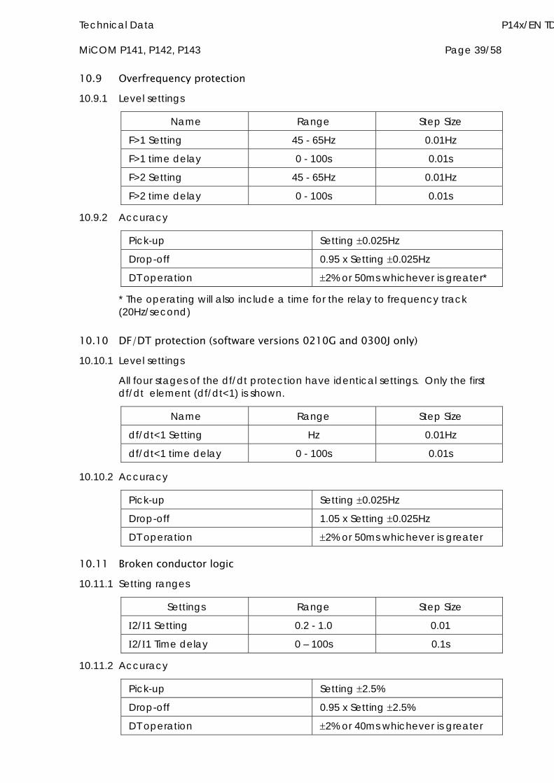
Technical Data P14x/EN TD MiCOM P141, P142, P143 Page 39/58
10.9 Overfrequency protection 10.9.1 Level settings
Name Range Step Size
F>1 Setting 45 - 65Hz 0.01Hz
F>1 time delay 0 - 100s 0.01s
F>2 Setting 45 - 65Hz 0.01Hz
F>2 time delay 0 - 100s 0.01s
10.9.2 Accuracy
Pick-up Setting 0.025Hz
Drop-off 0.95 x Setting 0.025Hz
DT operation 2% or 50ms whichever is greater*
* The operating will also include a time for the relay to frequency track (20Hz/second)
10.10 DF/DT protection (software versions 0210G and 0300J only) 10.10.1 Level settings
All four stages of the df/dt protection have identical settings. Only the first df/dt element (df/dt<1) is shown.
Name Range Step Size
df/dt<1 Setting Hz 0.01Hz
df/dt<1 time delay 0 - 100s 0.01s
10.10.2 Accuracy
Pick-up Setting 0.025Hz
Drop-off 1.05 x Setting 0.025Hz
DT operation 2% or 50ms whichever is greater
10.11 Broken conductor logic 10.11.1 Setting ranges
Settings Range Step Size
2/1 Setting 0.2 - 1.0 0.01
2/1 Time delay 0 – 100s 0.1s
10.11.2 Accuracy
Pick-up Setting 2.5%
Drop-off 0.95 x Setting 2.5%
DT operation 2% or 40ms whichever is greater

P14x/EN TD/B54 Technical Data Page 40/58 MiCOM P141, P142, P143
10.12 Thermal overload The thermal overload element can use either a single or a dual time constant equation, these are defined below:
1. Single time constant characteristic
t = - 1 Loge
2 - (1.05. TH)2
(2 - p2)
2. Dual time constant characteristic
0.4. e -t/1 + 0.6. e
-t/1 =
2 - (1.05. TH)2
(2 - p2)
The thermal state is stored in the relay non-volatile memory and will be retained during loss of auxiliary voltage to the relay.
p is the pre-fault steady state load
is the overload current
t is the time to trip
TH is the thermal trip current level
10.12.1 Setting ranges
Name Setting Range Step Size
Time constant Single or Dual -
Thermal trip current >> 0.08 - 4N 0.01N
Thermal alarm > 50 - 100% of >> 1% of >>
Time constant 1 1 - 200 minutes 1 minute
Time constant 2 1 - 200 minutes 1 minute
10.12.2 Accuracy
Pick-up Thermal alarm Calculated trip time 10%*
Thermal overload Calculated trip time 10%*
Cooling time accuracy 15% of theoretical
Repeatability <10%
* Operating time measured with applied current of 20% above thermal setting.
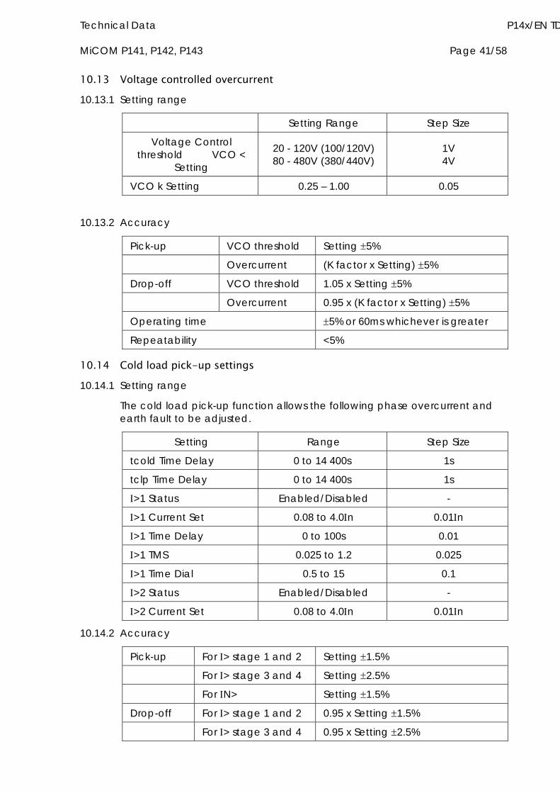
Technical Data P14x/EN TD MiCOM P141, P142, P143 Page 41/58
10.13 Voltage controlled overcurrent 10.13.1 Setting range
Setting Range Step Size
Voltage Control threshold VCO <
Setting
20 - 120V (100/120V) 80 - 480V (380/440V)
1V 4V
VCO k Setting 0.25 – 1.00 0.05
10.13.2 Accuracy
Pick-up VCO threshold Setting 5%
Overcurrent (K factor x Setting) 5%
Drop-off VCO threshold 1.05 x Setting 5%
Overcurrent 0.95 x (K factor x Setting) 5%
Operating time 5% or 60ms whichever is greater
Repeatability <5%
10.14 Cold load pick-up settings 10.14.1 Setting range
The cold load pick-up function allows the following phase overcurrent and earth fault to be adjusted.
Setting Range Step Size
tcold Time Delay 0 to 14 400s 1s
tclp Time Delay 0 to 14 400s 1s
>1 Status Enabled/Disabled -
>1 Current Set 0.08 to 4.0n 0.01n
>1 Time Delay 0 to 100s 0.01
>1 TMS 0.025 to 1.2 0.025
>1 Time Dial 0.5 to 15 0.1
>2 Status Enabled/Disabled -
>2 Current Set 0.08 to 4.0n 0.01n
10.14.2 Accuracy
Pick-up For > stage 1 and 2 Setting 1.5%
For > stage 3 and 4 Setting 2.5%
For N> Setting 1.5%
Drop-off For > stage 1 and 2 0.95 x Setting 1.5%
For > stage 3 and 4 0.95 x Setting 2.5%
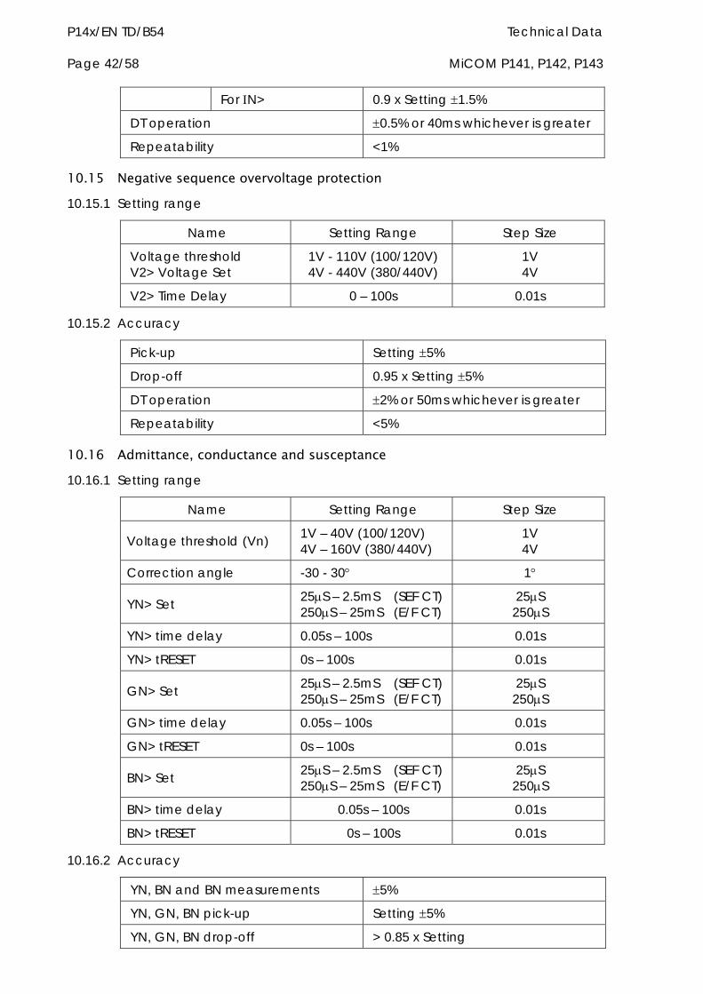
P14x/EN TD/B54 Technical Data Page 42/58 MiCOM P141, P142, P143
For N> 0.9 x Setting 1.5%
DT operation 0.5% or 40ms whichever is greater
Repeatability <1%
10.15 Negative sequence overvoltage protection 10.15.1 Setting range
Name Setting Range Step Size
Voltage threshold V2> Voltage Set
1V - 110V (100/120V) 4V - 440V (380/440V)
1V 4V
V2> Time Delay 0 – 100s 0.01s
10.15.2 Accuracy
Pick-up Setting 5%
Drop-off 0.95 x Setting 5%
DT operation 2% or 50ms whichever is greater
Repeatability <5%
10.16 Admittance, conductance and susceptance 10.16.1 Setting range
Name Setting Range Step Size
Voltage threshold (Vn) 1V – 40V (100/120V) 4V – 160V (380/440V)
1V 4V
Correction angle -30 - 30 1
YN> Set 25S – 2.5mS (SEF CT) 250S – 25mS (E/F CT)
25S 250S
YN> time delay 0.05s – 100s 0.01s
YN> tRESET 0s – 100s 0.01s
GN> Set 25S – 2.5mS (SEF CT) 250S – 25mS (E/F CT)
25S 250S
GN> time delay 0.05s – 100s 0.01s
GN> tRESET 0s – 100s 0.01s
BN> Set 25S – 2.5mS (SEF CT) 250S – 25mS (E/F CT)
25S 250S
BN> time delay 0.05s – 100s 0.01s
BN> tRESET 0s – 100s 0.01s
10.16.2 Accuracy
YN, BN and BN measurements 5%
YN, GN, BN pick-up Setting 5%
YN, GN, BN drop-off > 0.85 x Setting
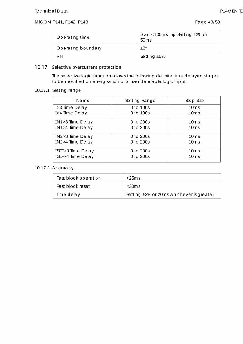
Technical Data P14x/EN TD MiCOM P141, P142, P143 Page 43/58
Operating time Start <100ms Trip Setting 2% or 50ms
Operating boundary 2
VN Setting 5%
10.17 Selective overcurrent protection The selective logic function allows the following definite time delayed stages to be modified on energisation of a user definable logic input.
10.17.1 Setting range
Name Setting Range Step Size >3 Time Delay >4 Time Delay
0 to 100s 0 to 100s
10ms 10ms
N1>3 Time Delay N1>4 Time Delay
0 to 200s 0 to 200s
10ms 10ms
N2>3 Time Delay N2>4 Time Delay
0 to 200s 0 to 200s
10ms 10ms
SEF>3 Time Delay SEF>4 Time Delay
0 to 200s 0 to 200s
10ms 10ms
10.17.2 Accuracy
Fast block operation <25ms
Fast block reset <30ms
Time delay Setting 2% or 20ms whichever is greater
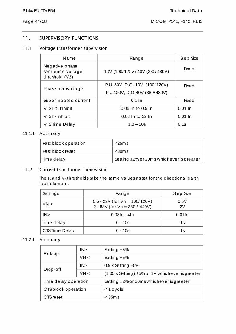
P14x/EN TD/B54 Technical Data Page 44/58 MiCOM P141, P142, P143
11. SUPERVISORY FUNCTIONS
11.1 Voltage transformer supervision
Name Range Step Size
Negative phase sequence voltage threshold (V2)
10V (100/120V) 40V (380/480V) Fixed
Phase overvoltage P.U. 30V, D.O. 10V (100/120V)
P.U.120V, D.O.40V (380/480V) Fixed
Superimposed current 0.1 n Fixed
VTS 2> Inhibit 0.05 n to 0.5 n 0.01 n
VTS > Inhibit 0.08 n to 32 n 0.01 n
VTS Time Delay 1.0 – 10s 0.1s
11.1.1 Accuracy
Fast block operation <25ms
Fast block reset <30ms
Time delay Setting 2% or 20ms whichever is greater
11.2 Current transformer supervision The N and VN thresholds take the same values as set for the directional earth fault element.
Settings Range Step Size
VN < 0.5 - 22V (for Vn = 100/120V) 2 - 88V (for Vn = 380 / 440V)
0.5V 2V
N> 0.08n - 4n 0.01n
Time delay t 0 - 10s 1s
CTS Time Delay 0 - 10s 1s
11.2.1 Accuracy
N> Setting 5% Pick-up
VN < Setting 5%
N> 0.9 x Setting 5% Drop-off
VN < (1.05 x Setting) 5% or 1V whichever is greater
Time delay operation Setting 2% or 20ms whichever is greater
CTS block operation < 1 cycle
CTS reset < 35ms
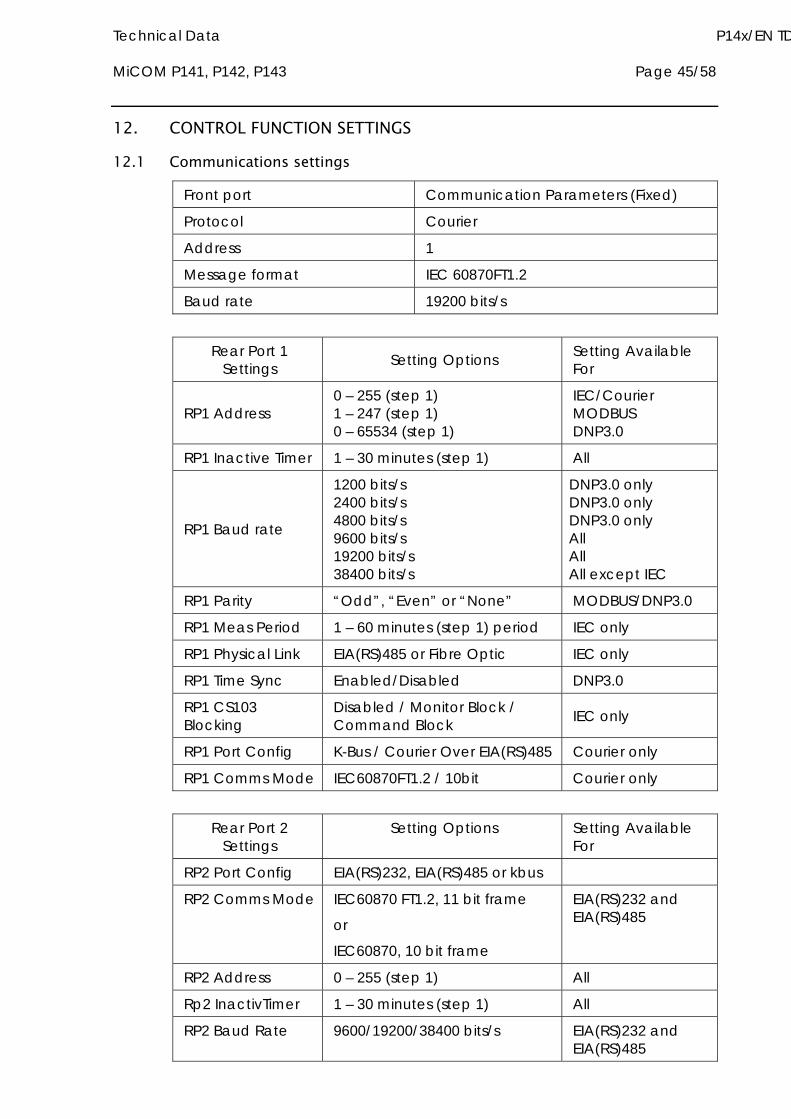
Technical Data P14x/EN TD MiCOM P141, P142, P143 Page 45/58
12. CONTROL FUNCTION SETTINGS
12.1 Communications settings
Front port Communication Parameters (Fixed)
Protocol Courier
Address 1
Message format IEC 60870FT1.2
Baud rate 19200 bits/s
Rear Port 1
Settings Setting Options Setting Available For
RP1 Address 0 – 255 (step 1) 1 – 247 (step 1) 0 – 65534 (step 1)
IEC/Courier MODBUS DNP3.0
RP1 Inactive Timer 1 – 30 minutes (step 1) All
RP1 Baud rate
1200 bits/s 2400 bits/s 4800 bits/s 9600 bits/s 19200 bits/s 38400 bits/s
DNP3.0 only DNP3.0 only DNP3.0 only All All All except IEC
RP1 Parity “Odd”, “Even” or “None” MODBUS/DNP3.0
RP1 Meas Period 1 – 60 minutes (step 1) period IEC only
RP1 Physical Link EIA(RS)485 or Fibre Optic IEC only
RP1 Time Sync Enabled/Disabled DNP3.0
RP1 CS103 Blocking
Disabled / Monitor Block / Command Block IEC only
RP1 Port Config K-Bus / Courier Over EIA(RS)485 Courier only
RP1 Comms Mode IEC60870FT1.2 / 10bit Courier only
Rear Port 2
Settings Setting Options Setting Available
For
RP2 Port Config EIA(RS)232, EIA(RS)485 or kbus
RP2 Comms Mode IEC60870 FT1.2, 11 bit frame
or
IEC60870, 10 bit frame
EIA(RS)232 and EIA(RS)485
RP2 Address 0 – 255 (step 1) All
Rp2 InactivTimer 1 – 30 minutes (step 1) All
RP2 Baud Rate 9600/19200/38400 bits/s EIA(RS)232 and EIA(RS)485
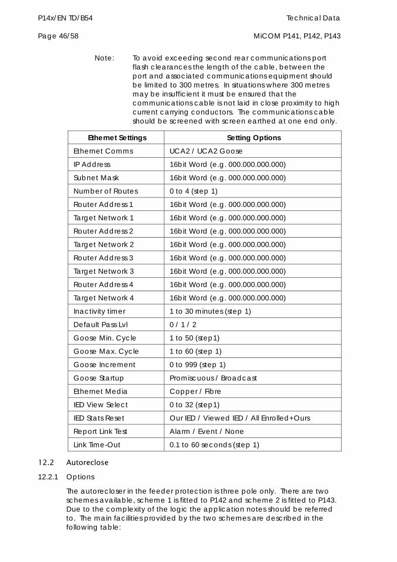
P14x/EN TD/B54 Technical Data Page 46/58 MiCOM P141, P142, P143
Note: To avoid exceeding second rear communications port flash clearances the length of the cable, between the port and associated communications equipment should be limited to 300 metres. In situations where 300 metres may be insufficient it must be ensured that the communications cable is not laid in close proximity to high current carrying conductors. The communications cable should be screened with screen earthed at one end only.
Ethernet Settings Setting Options
Ethernet Comms UCA2 / UCA2 Goose
IP Address 16bit Word (e.g. 000.000.000.000)
Subnet Mask 16bit Word (e.g. 000.000.000.000)
Number of Routes 0 to 4 (step 1)
Router Address 1 16bit Word (e.g. 000.000.000.000)
Target Network 1 16bit Word (e.g. 000.000.000.000)
Router Address 2 16bit Word (e.g. 000.000.000.000)
Target Network 2 16bit Word (e.g. 000.000.000.000)
Router Address 3 16bit Word (e.g. 000.000.000.000)
Target Network 3 16bit Word (e.g. 000.000.000.000)
Router Address 4 16bit Word (e.g. 000.000.000.000)
Target Network 4 16bit Word (e.g. 000.000.000.000)
Inactivity timer 1 to 30 minutes (step 1)
Default Pass Lvl 0 / 1 / 2
Goose Min. Cycle 1 to 50 (step1)
Goose Max. Cycle 1 to 60 (step 1)
Goose Increment 0 to 999 (step 1)
Goose Startup Promiscuous / Broadcast
Ethernet Media Copper / Fibre
IED View Select 0 to 32 (step1)
IED Stats Reset Our IED / Viewed IED / All Enrolled+Ours
Report Link Test Alarm / Event / None
Link Time-Out 0.1 to 60 seconds (step 1)
12.2 Autoreclose 12.2.1 Options
The autorecloser in the feeder protection is three pole only. There are two schemes available, scheme 1 is fitted to P142 and scheme 2 is fitted to P143. Due to the complexity of the logic the application notes should be referred to. The main facilities provided by the two schemes are described in the following table:
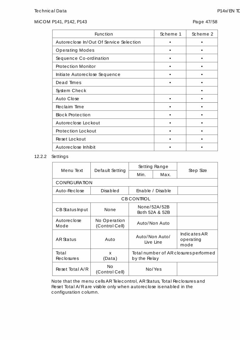
Technical Data P14x/EN TD MiCOM P141, P142, P143 Page 47/58
Function Scheme 1 Scheme 2
Autoreclose In/Out Of Service Selection • •
Operating Modes • •
Sequence Co-ordination • •
Protection Monitor • •
Initiate Autoreclose Sequence • •
Dead Times • •
System Check •
Auto Close • •
Reclaim Time • •
Block Protection • •
Autoreclose Lockout • •
Protection Lockout • •
Reset Lockout • •
Autoreclose Inhibit • •
12.2.2 Settings
Setting Range Menu Text Default Setting
Min. Max. Step Size
CONFIGURATION
Auto-Reclose Disabled Enable / Disable
CB CONTROL
CB Status Input None None/52A/52B Both 52A & 52B
Autoreclose Mode
No Operation (Control Cell) Auto/Non Auto
AR Status Auto Auto/Non Auto/ Live Line
Indicates AR operating mode
Total Reclosures
x (Data)
Total number of AR closures performed by the Relay
Reset Total A/R No (Control Cell) No/Yes
Note that the menu cells AR Telecontrol, AR Status, Total Reclosures and Reset Total A/R are visible only when autoreclose is enabled in the configuration column.
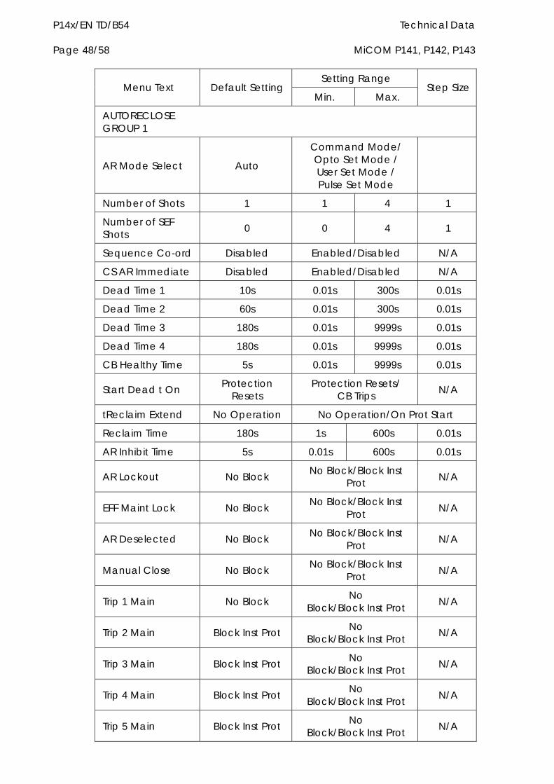
P14x/EN TD/B54 Technical Data Page 48/58 MiCOM P141, P142, P143
Setting Range Menu Text Default Setting
Min. Max. Step Size
AUTORECLOSE GROUP 1
AR Mode Select Auto
Command Mode/ Opto Set Mode / User Set Mode / Pulse Set Mode
Number of Shots 1 1 4 1
Number of SEF Shots 0 0 4 1
Sequence Co-ord Disabled Enabled/Disabled N/A
CS AR Immediate Disabled Enabled/Disabled N/A
Dead Time 1 10s 0.01s 300s 0.01s
Dead Time 2 60s 0.01s 300s 0.01s
Dead Time 3 180s 0.01s 9999s 0.01s
Dead Time 4 180s 0.01s 9999s 0.01s
CB Healthy Time 5s 0.01s 9999s 0.01s
Start Dead t On Protection Resets
Protection Resets/ CB Trips N/A
tReclaim Extend No Operation No Operation/On Prot Start
Reclaim Time 180s 1s 600s 0.01s
AR Inhibit Time 5s 0.01s 600s 0.01s
AR Lockout No Block No Block/Block Inst Prot N/A
EFF Maint Lock No Block No Block/Block Inst Prot N/A
AR Deselected No Block No Block/Block Inst Prot N/A
Manual Close No Block No Block/Block Inst Prot N/A
Trip 1 Main No Block No Block/Block Inst Prot N/A
Trip 2 Main Block Inst Prot No Block/Block Inst Prot N/A
Trip 3 Main Block Inst Prot No Block/Block Inst Prot N/A
Trip 4 Main Block Inst Prot No Block/Block Inst Prot N/A
Trip 5 Main Block Inst Prot No Block/Block Inst Prot N/A
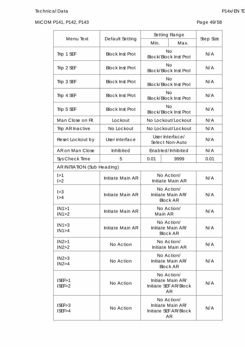
Technical Data P14x/EN TD MiCOM P141, P142, P143 Page 49/58
Setting Range Menu Text Default Setting
Min. Max. Step Size
Trip 1 SEF Block Inst Prot No Block/Block Inst Prot N/A
Trip 2 SEF Block Inst Prot No Block/Block Inst Prot N/A
Trip 3 SEF Block Inst Prot No Block/Block Inst Prot N/A
Trip 4 SEF Block Inst Prot No Block/Block Inst Prot N/A
Trip 5 SEF Block Inst Prot No Block/Block Inst Prot N/A
Man Close on Flt Lockout No Lockout/Lockout N/A
Trip AR Inactive No Lockout No Lockout/Lockout N/A
Reset Lockout by User interface User Interface/ Select Non-Auto N/A
AR on Man Close Inhibited Enabled/Inhibited N/A
Sys Check Time 5 0.01 9999 0.01
AR INITIATION (Sub Heading)
>1 >2 Initiate Main AR No Action/
Initiate Main AR N/A
>3 >4 Initiate Main AR
No Action/ Initiate Main AR/
Block AR N/A
N1>1 N1>2 Initiate Main AR No Action/
Main AR N/A
N1>3 N1>4 Initiate Main AR
No Action/ Initiate Main AR/
Block AR N/A
N2>1 N2>2 No Action No Action/
Initiate Main AR N/A
N2>3 N2>4 No Action
No Action/ Initiate Main AR/
Block AR N/A
SEF>1 SEF>2 No Action
No Action/ Initiate Main AR/
Initiate SEF AR/Block AR
N/A
SEF>3 SEF>4 No Action
No Action/ Initiate Main AR/
Initiate SEF AR/Block AR
N/A
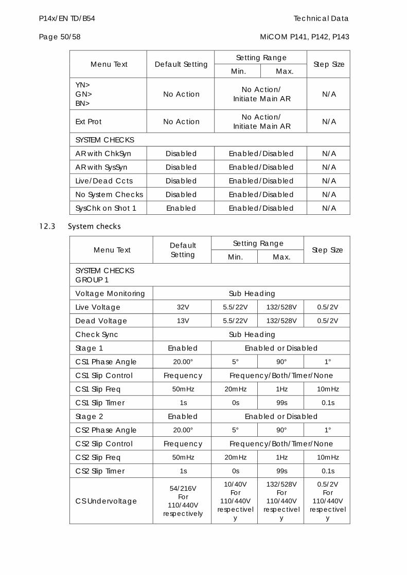
P14x/EN TD/B54 Technical Data Page 50/58 MiCOM P141, P142, P143
Setting Range Menu Text Default Setting
Min. Max. Step Size
YN> GN> BN>
No Action No Action/ Initiate Main AR N/A
Ext Prot No Action No Action/ Initiate Main AR N/A
SYSTEM CHECKS
AR with ChkSyn Disabled Enabled/Disabled N/A
AR with SysSyn Disabled Enabled/Disabled N/A
Live/Dead Ccts Disabled Enabled/Disabled N/A
No System Checks Disabled Enabled/Disabled N/A
SysChk on Shot 1 Enabled Enabled/Disabled N/A
12.3 System checks
Setting Range Menu Text Default
Setting Min. Max. Step Size
SYSTEM CHECKS GROUP 1
Voltage Monitoring Sub Heading
Live Voltage 32V 5.5/22V 132/528V 0.5/2V
Dead Voltage 13V 5.5/22V 132/528V 0.5/2V
Check Sync Sub Heading
Stage 1 Enabled Enabled or Disabled
CS1 Phase Angle 20.00° 5° 90° 1°
CS1 Slip Control Frequency Frequency/Both/Timer/None
CS1 Slip Freq 50mHz 20mHz 1Hz 10mHz
CS1 Slip Timer 1s 0s 99s 0.1s
Stage 2 Enabled Enabled or Disabled
CS2 Phase Angle 20.00° 5° 90° 1°
CS2 Slip Control Frequency Frequency/Both/Timer/None
CS2 Slip Freq 50mHz 20mHz 1Hz 10mHz
CS2 Slip Timer 1s 0s 99s 0.1s
CS Undervoltage
54/216V For
110/440V respectively
10/40V For
110/440V respectivel
y
132/528V For
110/440V respectivel
y
0.5/2V For
110/440V respectivel
y
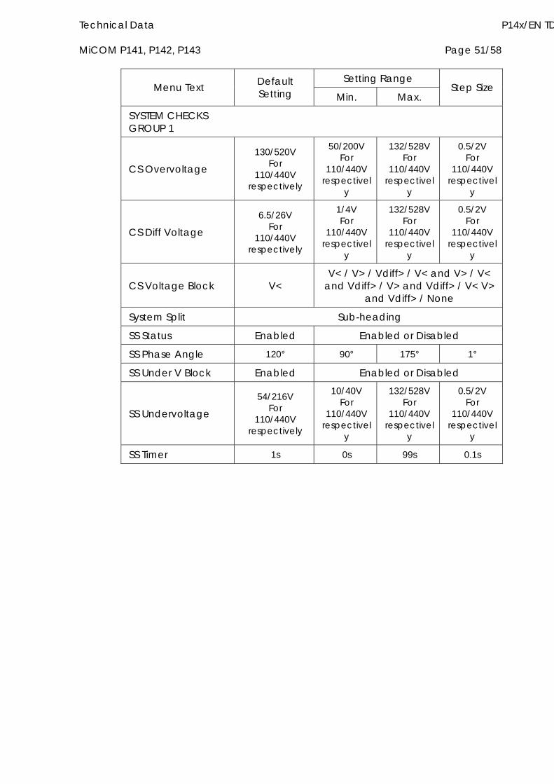
Technical Data P14x/EN TD MiCOM P141, P142, P143 Page 51/58
Setting Range Menu Text Default
Setting Min. Max. Step Size
SYSTEM CHECKS GROUP 1
CS Overvoltage
130/520V For
110/440V respectively
50/200V For
110/440V respectivel
y
132/528V For
110/440V respectivel
y
0.5/2V For
110/440V respectivel
y
CS Diff Voltage
6.5/26V For
110/440V respectively
1/4V For
110/440V respectivel
y
132/528V For
110/440V respectivel
y
0.5/2V For
110/440V respectivel
y
CS Voltage Block V< V< / V> / Vdiff> / V< and V> / V<
and Vdiff> / V> and Vdiff> / V< V> and Vdiff> / None
System Split Sub-heading
SS Status Enabled Enabled or Disabled
SS Phase Angle 120° 90° 175° 1°
SS Under V Block Enabled Enabled or Disabled
SS Undervoltage
54/216V For
110/440V respectively
10/40V For
110/440V respectivel
y
132/528V For
110/440V respectivel
y
0.5/2V For
110/440V respectivel
y
SS Timer 1s 0s 99s 0.1s
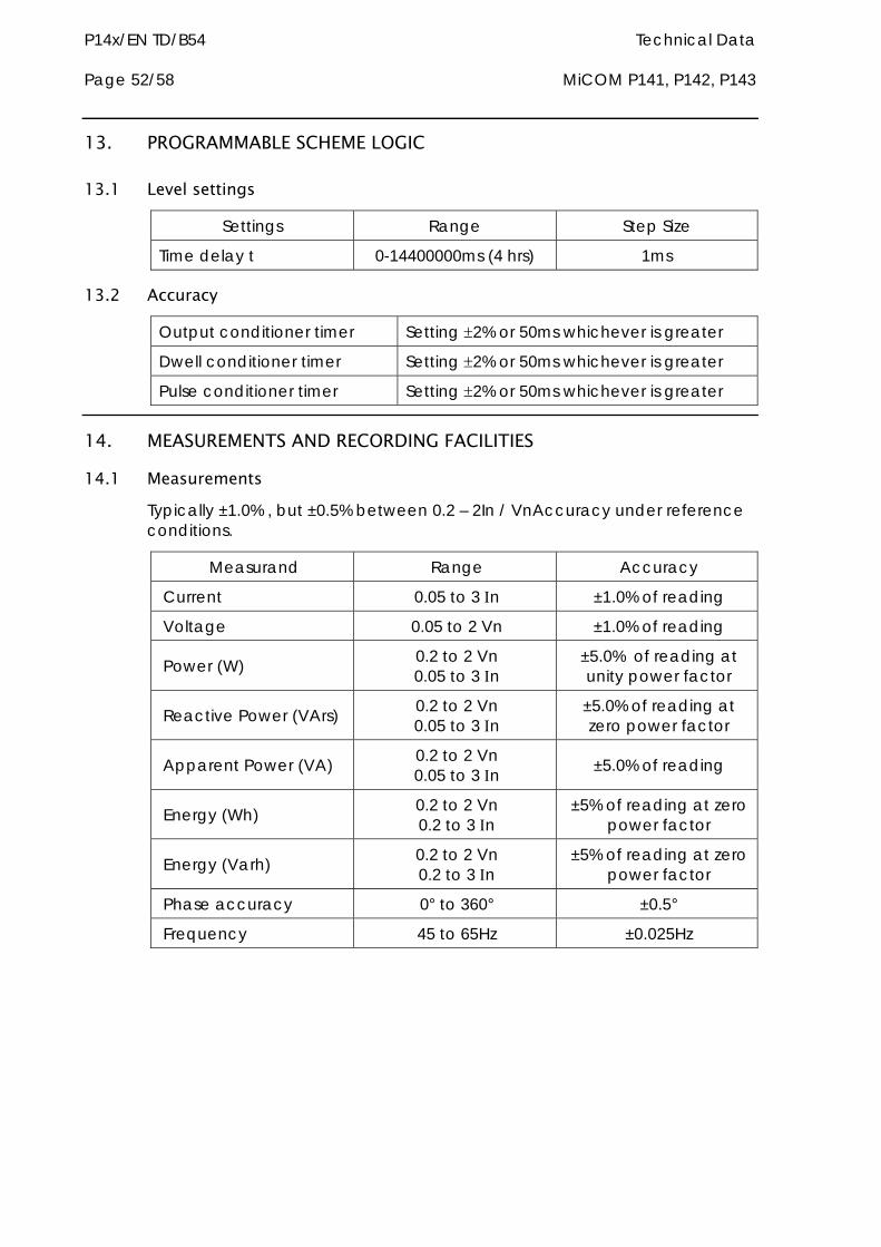
P14x/EN TD/B54 Technical Data Page 52/58 MiCOM P141, P142, P143
13. PROGRAMMABLE SCHEME LOGIC
13.1 Level settings
Settings Range Step Size
Time delay t 0-14400000ms (4 hrs) 1ms
13.2 Accuracy
Output conditioner timer Setting 2% or 50ms whichever is greater
Dwell conditioner timer Setting 2% or 50ms whichever is greater
Pulse conditioner timer Setting 2% or 50ms whichever is greater
14. MEASUREMENTS AND RECORDING FACILITIES
14.1 Measurements Typically ±1.0% , but ±0.5% between 0.2 – 2In / VnAccuracy under reference conditions.
Measurand Range Accuracy
Current 0.05 to 3 n ±1.0% of reading
Voltage 0.05 to 2 Vn ±1.0% of reading
Power (W) 0.2 to 2 Vn 0.05 to 3 n
±5.0% of reading at unity power factor
Reactive Power (VArs) 0.2 to 2 Vn 0.05 to 3 n
±5.0% of reading at zero power factor
Apparent Power (VA) 0.2 to 2 Vn 0.05 to 3 n ±5.0% of reading
Energy (Wh) 0.2 to 2 Vn 0.2 to 3 n
±5% of reading at zero power factor
Energy (Varh) 0.2 to 2 Vn 0.2 to 3 n
±5% of reading at zero power factor
Phase accuracy 0° to 360° ±0.5°
Frequency 45 to 65Hz ±0.025Hz
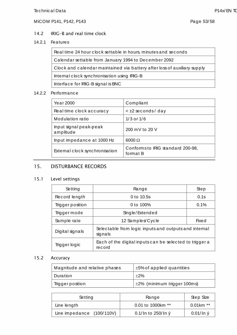
Technical Data P14x/EN TD MiCOM P141, P142, P143 Page 53/58
14.2 IRIG-B and real time clock 14.2.1 Features
Real time 24 hour clock settable in hours, minutes and seconds
Calendar settable from January 1994 to December 2092
Clock and calendar maintained via battery after loss of auxiliary supply
Internal clock synchronisation using IRIG-B
Interface for IRIG-B signal is BNC
14.2.2 Performance
Year 2000 Compliant
Real time clock accuracy < ±2 seconds / day
Modulation ratio 1/3 or 1/6
Input signal peak-peak amplitude 200 mV to 20 V
Input impedance at 1000 Hz 6000
External clock synchronisation Conforms to IRIG standard 200-98, format B
15. DISTURBANCE RECORDS
15.1 Level settings
Setting Range Step
Record length 0 to 10.5s 0.1s
Trigger position 0 to 100% 0.1%
Trigger mode Single/Extended
Sample rate 12 Samples/Cycle Fixed
Digital signals Selectable from logic inputs and outputs and internal signals
Trigger logic Each of the digital inputs can be selected to trigger a record
15.2 Accuracy
Magnitude and relative phases 5% of applied quantities
Duration 2%
Trigger position 2% (minimum trigger 100ms)
Setting Range Step Size
Line length 0.01 to 1000km ** 0.01km **
Line impedance (100/110V) 0.1/n to 250/n ý 0.01/n ý
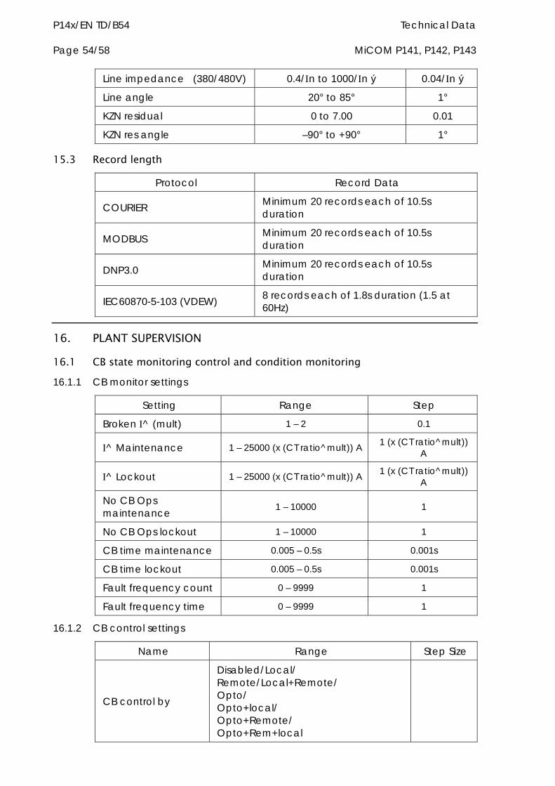
P14x/EN TD/B54 Technical Data Page 54/58 MiCOM P141, P142, P143
Line impedance (380/480V) 0.4/n to 1000/n ý 0.04/n ý
Line angle 20° to 85° 1°
KZN residual 0 to 7.00 0.01
KZN res angle –90° to +90° 1°
15.3 Record length
Protocol Record Data
COURIER Minimum 20 records each of 10.5s duration
MODBUS Minimum 20 records each of 10.5s duration
DNP3.0 Minimum 20 records each of 10.5s duration
IEC60870-5-103 (VDEW) 8 records each of 1.8s duration (1.5 at 60Hz)
16. PLANT SUPERVISION
16.1 CB state monitoring control and condition monitoring 16.1.1 CB monitor settings
Setting Range Step
Broken ^ (mult) 1 – 2 0.1
^ Maintenance 1 – 25000 (x (CT ratio^mult)) A 1 (x (CT ratio^mult)) A
^ Lockout 1 – 25000 (x (CT ratio^mult)) A 1 (x (CT ratio^mult)) A
No CB Ops maintenance 1 – 10000 1
No CB Ops lockout 1 – 10000 1
CB time maintenance 0.005 – 0.5s 0.001s
CB time lockout 0.005 – 0.5s 0.001s
Fault frequency count 0 – 9999 1
Fault frequency time 0 – 9999 1
16.1.2 CB control settings
Name Range Step Size
CB control by
Disabled/Local/ Remote/Local+Remote/ Opto/ Opto+local/ Opto+Remote/ Opto+Rem+local
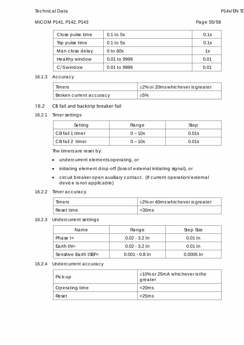
Technical Data P14x/EN TD MiCOM P141, P142, P143 Page 55/58
Close pulse time 0.1 to 5s 0.1s
Trip pulse time 0.1 to 5s 0.1s
Man close delay 0 to 60s 1s
Healthy window 0.01 to 9999 0.01
C/S window 0.01 to 9999 0.01
16.1.3 Accuracy
Timers 2% or 20ms whichever is greater
Broken current accuracy 5%
16.2 CB fail and backtrip breaker fail 16.2.1 Timer settings
Setting Range Step
CB fail 1 timer 0 – 10s 0.01s
CB fail 2 timer 0 – 10s 0.01s
The timers are reset by:
undercurrent elements operating, or
initiating element drop-off (loss of external initiating signal), or
circuit breaker open auxiliary contact. (If current operation/external device is not applicable)
16.2.2 Timer accuracy
Timers 2% or 40ms whichever is greater
Reset time <30ms
16.2.3 Undercurrent settings
Name Range Step Size
Phase < 0.02 - 3.2 n 0.01 n
Earth N< 0.02 - 3.2 n 0.01 n
Sensitive Earth SEF< 0.001 - 0.8 n 0.0005 n
16.2.4 Undercurrent accuracy
Pick-up 10% or 25mA whichever is the greater
Operating time <20ms
Reset <25ms

P14x/EN TD/B54 Technical Data Page 56/58 MiCOM P141, P142, P143
17. INPUT AND OUTPUT SETTING RANGES
17.1 CT and VT ratio settings The primary and secondary rating can be independently set for each set of CT or VT inputs, for example the earth fault CT ratio can be different to that used for the phase currents. Note, VT primary and secondary values are phase-phase rms values.
Primary Range Secondary Range
Current transformer 1 to 30000 Amps step size 1A 1 or 5 Amps
Voltage transformer 100V to 1000 kV step size 1V
80 to 140V (Vn = 100/120V) 320 to 560V (Vn = 380/480V)
18. BATTERY LIFE Battery life (assuming relay energised for 90% of time) > 10 years
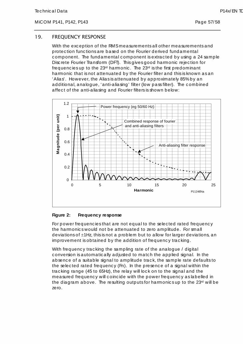
Technical Data P14x/EN TD MiCOM P141, P142, P143 Page 57/58
19. FREQUENCY RESPONSE With the exception of the RMS measurements all other measurements and protection functions are based on the Fourier derived fundamental component. The fundamental component is extracted by using a 24 sample Discrete Fourier Transform (DFT). This gives good harmonic rejection for frequencies up to the 23rd harmonic. The 23rd is the first predominant harmonic that is not attenuated by the Fourier filter and this is known as an ‘Alias’. However, the Alias is attenuated by approximately 85% by an additional, analogue, ‘anti-aliasing’ filter (low pass filter). The combined affect of the anti-aliasing and Fourier filters is shown below:
0
0.2
0.4
0.6
0.8
1
1.2
0 5 10 15 20 25Harmonic
Ma
gn
itu
de
(p
er
un
it)
Combined response of fourierand anti-aliasing filters
Anti-aliasing filter response
Power frequency (eg 50/60 Hz)
P1124ENa
Figure 2: Frequency response
For power frequencies that are not equal to the selected rated frequency the harmonics would not be attenuated to zero amplitude. For small deviations of 1Hz, this is not a problem but to allow for larger deviations, an improvement is obtained by the addition of frequency tracking.
With frequency tracking the sampling rate of the analogue / digital conversion is automatically adjusted to match the applied signal. In the absence of a suitable signal to amplitude track, the sample rate defaults to the selected rated frequency (Fn). In the presence of a signal within the tracking range (45 to 65Hz), the relay will lock on to the signal and the measured frequency will coincide with the power frequency as labelled in the diagram above. The resulting outputs for harmonics up to the 23rd will be zero.

P14x/EN TD/B54 Technical Data Page 58/58 MiCOM P141, P142, P143

SCADA Communications P14x/EN CT/C54 MiCOM P141, P142, P143
SCADA COMMUNICATIONS

P14x/EN CT/C54 SCADA Communications MiCOM P141, P142, P143
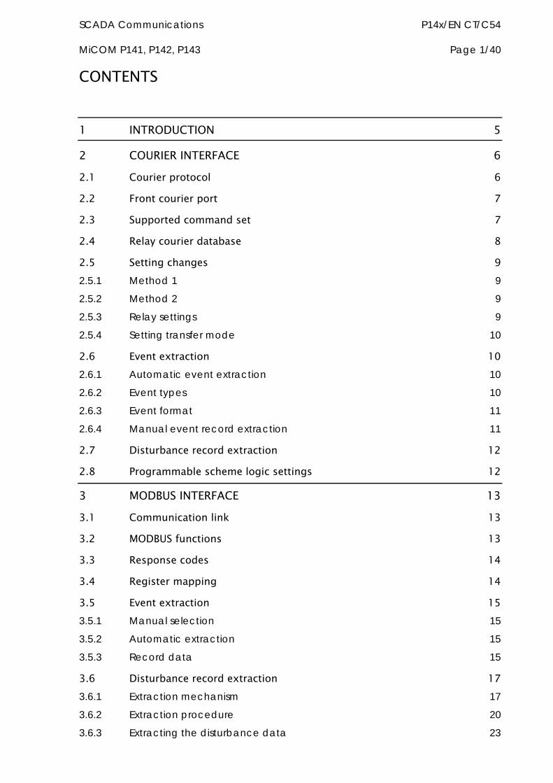
SCADA Communications P14x/EN CT/C54 MiCOM P141, P142, P143 Page 1/40
CONTENTS
1 INTRODUCTION 5
2 COURIER INTERFACE 6 2.1 Courier protocol 6
2.2 Front courier port 7
2.3 Supported command set 7
2.4 Relay courier database 8
2.5 Setting changes 9 2.5.1 Method 1 9
2.5.2 Method 2 9
2.5.3 Relay settings 9
2.5.4 Setting transfer mode 10
2.6 Event extraction 10 2.6.1 Automatic event extraction 10
2.6.2 Event types 10
2.6.3 Event format 11
2.6.4 Manual event record extraction 11
2.7 Disturbance record extraction 12
2.8 Programmable scheme logic settings 12
3 MODBUS INTERFACE 13 3.1 Communication link 13
3.2 MODBUS functions 13
3.3 Response codes 14
3.4 Register mapping 14
3.5 Event extraction 15 3.5.1 Manual selection 15
3.5.2 Automatic extraction 15
3.5.3 Record data 15
3.6 Disturbance record extraction 17 3.6.1 Extraction mechanism 17
3.6.2 Extraction procedure 20
3.6.3 Extracting the disturbance data 23
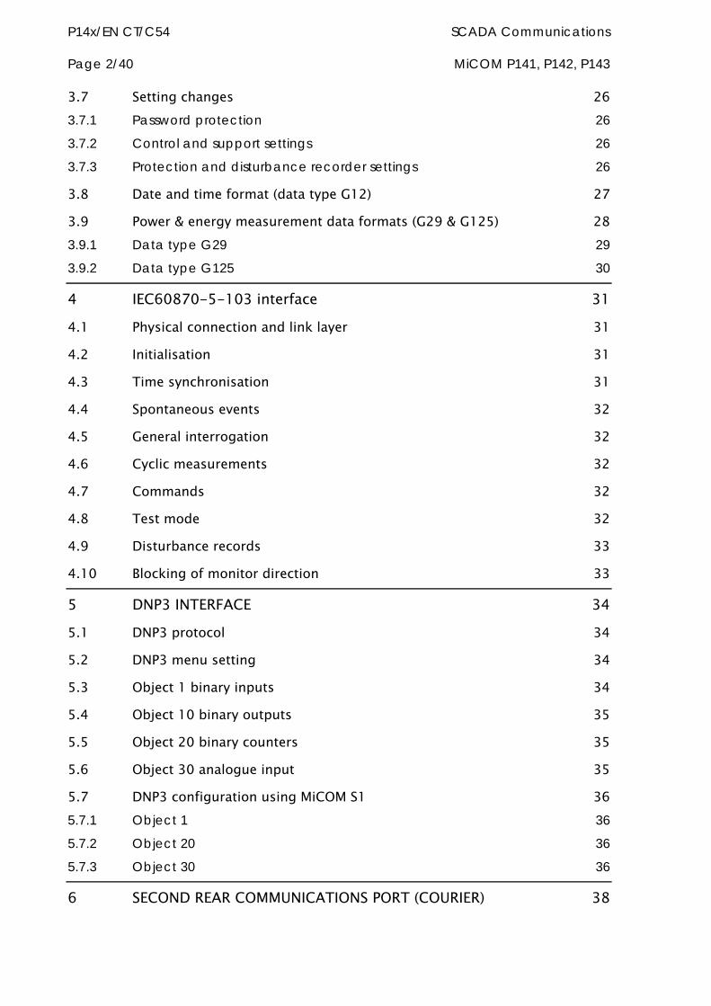
P14x/EN CT/C54 SCADA Communications Page 2/40 MiCOM P141, P142, P143
3.7 Setting changes 26 3.7.1 Password protection 26
3.7.2 Control and support settings 26
3.7.3 Protection and disturbance recorder settings 26
3.8 Date and time format (data type G12) 27
3.9 Power & energy measurement data formats (G29 & G125) 28 3.9.1 Data type G29 29
3.9.2 Data type G125 30
4 IEC60870-5-103 interface 31 4.1 Physical connection and link layer 31
4.2 Initialisation 31
4.3 Time synchronisation 31
4.4 Spontaneous events 32
4.5 General interrogation 32
4.6 Cyclic measurements 32
4.7 Commands 32
4.8 Test mode 32
4.9 Disturbance records 33
4.10 Blocking of monitor direction 33
5 DNP3 INTERFACE 34 5.1 DNP3 protocol 34
5.2 DNP3 menu setting 34
5.3 Object 1 binary inputs 34
5.4 Object 10 binary outputs 35
5.5 Object 20 binary counters 35
5.6 Object 30 analogue input 35
5.7 DNP3 configuration using MiCOM S1 36 5.7.1 Object 1 36
5.7.2 Object 20 36
5.7.3 Object 30 36
6 SECOND REAR COMMUNICATIONS PORT (COURIER) 38
SCADA Communications P14x/EN CT/C54 MiCOM P141, P142, P143 Page 3/40
6.1 Courier protocol 38
6.2 Event extraction 38
6.3 Disturbance record extraction 39
6.4 Connection to the second rear port 39
7 SK5 PORT CONNECTION 40

P14x/EN CT/C54 SCADA Communications Page 4/40 MiCOM P141, P142, P143
SCADA Communications P14x/EN CT/C54 MiCOM P141, P142, P143 Page 5/40
1 INTRODUCTION This section describes the remote interfaces of the MiCOM relay in enough detail to allow integration within a substation communication network. As has been outlined in earlier sections, the relay supports a choice of one of four protocols via the rear communication interface. This is in addition to the front serial interface and 2nd rear communications port, which supports the Courier protocol only.
The rear EIA(RS)485 interface is isolated and is suitable for permanent connection whichever protocol is selected. The advantage of this type of connection is that up to 32 relays can be ‘daisy chained’ together using a simple twisted pair electrical connection.
For each of the protocol options, the supported functions/commands will be listed together with the database definition. The operation of standard procedures such as extraction of event, fault and disturbance records, or setting changes, will also be described.
It should be noted that the descriptions contained within this section do not aim to fully detail the protocol itself. The relevant documentation for the protocol should be referred to for this information. This section serves to describe the specific implementation of the protocol in the relay.
P14x/EN CT/C54 SCADA Communications Page 6/40 MiCOM P141, P142, P143
2 COURIER INTERFACE
2.1 Courier protocol Courier is an ALSTOM Grid communication protocol. The concept of the protocol is that a standard set of commands are used to access a database of settings and data within the relay. This allows a generic master to be able to communicate with different slave devices. The application specific aspects are contained within the database itself rather than the commands used to interrogate it, i.e. the master station does not need to be pre-configured.
The same protocol can be used via two physical links K-Bus or EIA(RS)232.
K-Bus is based on EIA(RS)485 voltage levels with HDLC FM0 encoded synchronous signalling and its own frame format. The K-Bus twisted pair connection is unpolarised, whereas the EIA(RS)485 and EIA(RS)232 interfaces are polarised.
The EIA(RS)232 interface uses the IEC60870-5 FT1.2 frame format.
The relay supports an IEC60870-5 FT1.2 connection on the front-port. This is intended for temporary local connection and is not suitable for permanent connection. This interface uses a fixed baud rate, 11-bit frame, and a fixed device address.
The rear interface is used to provide a permanent connection for K-Bus and allows multi-drop connection. It should be noted that although K-Bus is based on EIA(RS)485 voltage levels it is a synchronous HDLC protocol using FM0 encoding. It is not possible to use a standard EIA(RS)232 to EIA(RS)485 converter to convert IEC60870-5 FT1.2 frames to K-Bus. Nor is it possible to connect K-Bus to an EIA(RS)485 computer port. A protocol converter, such as the KITZ101, should be employed for this purpose.
The following documentation should be referred to for a detailed description of the Courier protocol, command-set and link description.
SCADA Communications P14x/EN CT/C54 MiCOM P141, P142, P143 Page 7/40
R6509 K-Bus Interface Guide
R6510 IEC60870 Interface Guide
R6511 Courier Protocol
R6512 Courier User Guide
2.2 Front courier port The front EIA(RS)2321 9 pin port supports the Courier protocol for one to one communication. It is designed for use during installation and commissioning/maintenance and is not suitable for permanent connection. Since this interface will not be used to link the relay to a substation communication system, some of the features of Courier are not implemented. These are as follows:
Automatic extraction of Event Records:
Courier Status byte does not support the Event flag
Send Event/Accept Event commands are not implemented
Automatic extraction of Disturbance records:
Courier Status byte does not support the Disturbance flag
Busy Response Layer:
Courier Status byte does not support the Busy flag, the only response to a request will be the final data
Fixed Address:
The address of the front Courier port is always 1, the Change Device address command is not supported.
Fixed Baud Rate:
19200 bps
It should be noted that although automatic extraction of event and disturbance records is not supported it is possible to manually access this data via the front port.
2.3 Supported command set The following Courier commands are supported by the relay:
Protocol Layer
Reset Remote Link
Poll Status
Poll Buffer*
Low Level Commands
Send Event*
1 This port is actually compliant to EIA(RS)574; the 9-pin version of EIA(RS)232, see www.tiaonline.org.
P14x/EN CT/C54 SCADA Communications Page 8/40 MiCOM P141, P142, P143
Accept Event*
Send Block
Store Block Identifier
Store Block Footer
Menu Browsing
Get Column Headings
Get Column Text
Get Column Values
Get Strings
Get Text
Get Value
Get Column Setting Limits
Setting Changes
Enter Setting Mode
Preload Setting
Abort Setting
Execute Setting
Reset Menu Cell
Set Value
Control Commands
Select Setting Group
Change Device Address*
Set Real Time
Note: Commands indicated with a * are not supported via the front Courier port.
2.4 Relay courier database The Courier database is a two dimensional structure with each cell in the database being referenced by a row and column address. Both the column and the row can take a range from 0 to 255. Addresses in the database are specified as hexadecimal values, e.g. 0A02 is column 0A (10 decimal) row 02. Associated settings/data will be part of the same column, row zero of the column contains a text string to identify the contents of the column, i.e. a column heading.
P14x/EN GC contains the complete database definition for the relay. For each cell location the following information is stated:
Cell Text
Cell Datatype
SCADA Communications P14x/EN CT/C54 MiCOM P141, P142, P143 Page 9/40
Cell value
Whether the cell is settable, if so
Minimum value
Maximum value
Step size
Password Level required to allow setting changes
String information (for Indexed String or Binary flag cells)
2.5 Setting changes (See R6512, Courier User Guide - Chapter 9)
Courier provides two mechanisms for making setting changes, both of these are supported by the relay. Either method can be used for editing any of the settings within the relay database.
2.5.1 Method 1
This uses a combination of three commands to perform a settings change:
Enter Setting Mode - checks that the cell is settable and returns the limits
Preload Setting - Places a new value to the cell, this value is echoed to ensure that setting corruption has not taken place, the validity of the setting is not checked by this action.
Execute Setting - Confirms the setting change, if the change is valid then a positive response will be returned, if the setting change fails then an error response will be returned.
Abort Setting - This command can be used to abandon the setting change.
This is the most secure method and is ideally suited to on-line editors as the setting limits are taken from the relay before the setting change is made. However this method can be slow if many settings are being changed as three commands are required for each change.
2.5.2 Method 2
The Set Value command can be used to directly change a setting, the response to this command will be either a positive confirm or an error code to indicate the nature of a failure. This command can be used to implement a setting more rapidly then the previous method, however the limits are not extracted from the relay. This method is most suitable for off-line setting editors such as MiCOM S1, or for the issuing of pre-configured (SCADA) control commands.
2.5.3 Relay settings
There are three categories of settings within the relay database
Control and Support
Disturbance Recorder
Protection Settings Group
P14x/EN CT/C54 SCADA Communications Page 10/40 MiCOM P141, P142, P143
Setting changes made to the control and support settings are implemented immediately and stored in non-volatile memory. Changes made to either the Disturbance recorder settings or the Protection Settings Groups are stored in a ‘scratchpad’ memory and are not immediately implemented by the relay.
To action setting changes stored in the scratchpad the Save Changes cell in the Configuration column must be written to. This allows the changes to either be confirmed and stored in non-volatile memory, or the setting changes to be aborted.
2.5.4 Setting transfer mode
If it is necessary to transfer all of the relay settings to or from the relay a cell within the Communication System Data column can be used. This cell (location BF03) when set to 1 makes all of the relay settings visible. Any setting changes made, with the relay set in this mode, are stored in scratchpad memory (including control and support settings). When the value of BF03 is set back to 0 any setting changes are verified and stored in non-volatile memory.
2.6 Event extraction Events can be extracted either automatically (rear port only) or manually (either Courier port). For automatic extraction all events are extracted in sequential order using the standard Courier event mechanism, this includes fault/maintenance data if appropriate. The manual approach allows the user to select events, faults, or maintenance data at random from the stored records.
2.6.1 Automatic event extraction
(See Chapter 7 Courier User Guide, publication R6512)
This method is intended for continuous extraction of event and fault information as it is produced. It is only supported via the rear Courier port.
When new event information is created the Event bit is set within the Status byte, this indicates to the Master device that event information is available. The oldest, unextracted event can be extracted from the relay using the Send Event command. The relay will respond with the event data, which will be either a Courier Type 0 or Type 3 event. The Type 3 event is used for fault records and maintenance records.
Once an event has been extracted from the relay, the Accept Event can be used to confirm that the event has been successfully extracted. If all events have been extracted then the event bit will reset, if there are more events still to be extracted the next event can be accessed using the Send Event command as before.
2.6.2 Event types
Events will be created by the relay under the following circumstances:
Change of state of output contact
Change of state of opto input
Protection element operation
SCADA Communications P14x/EN CT/C54 MiCOM P141, P142, P143 Page 11/40
Alarm condition
Setting Change
Password entered/timed-out
Fault Record (Type 3 Courier Event)
Maintenance record (Type 3 Courier Event)
2.6.3 Event format
The Send Event command results in the following fields being returned by the relay:
Cell Reference
Timestamp
Cell Text
Cell Value
The menu database, P14x/EN GC, contains a table of the events created by the relay and indicates how the contents of the above fields are interpreted. Fault records and Maintenance records will return a Courier Type 3 event, which contains the above fields together with two additional fields:
Event extraction column
Event number
These events contain additional information that is extracted from the relay using the referenced extraction column. Row 01 of the extraction column contains a setting that allows the fault/maintenance record to be selected. This setting should be set to the event number value returned within the record, the extended data can be extracted from the relay by uploading the text and data from the column.
2.6.4 Manual event record extraction
Column 01 of the database can be used for manual viewing of event, fault, and maintenance records. The contents of this column will depend on the nature of the record selected. It is possible to select events by event number and to directly select a fault record or maintenance record by number.
Event Record selection (Row 01) - This cell can be set to a value between 0 to 249 to select which of the 250 stored events is selected, 0 will select the most recent record; 249 the oldest stored record. For simple event records, (Type 0) cells 0102 to 0105 contain the event details. A single cell is used to represent each of the event fields. If the event selected is a fault or maintenance record (Type 3) then the remainder of the column will contain the additional information.
Fault Record Selection (Row 05) – This cell can be used to directly select a fault record using a value between 0 and 4 to select one of up to five stored fault records. (0 will be the most recent fault and 4 will be the oldest). The column will then contain the details of the fault record selected.
Maintenance Record Selection (Row F0) – This cell can be used to select a maintenance record using a value between 0 and 4 and operates in a similar way to the fault record selection.
P14x/EN CT/C54 SCADA Communications Page 12/40 MiCOM P141, P142, P143
It should be noted that if this column is used to extract event information from the relay the number associated with a particular record will change when a new event or fault occurs.
2.7 Disturbance record extraction The stored disturbance records within the relay are accessible in a compressed format via the Courier interface. The records are extracted using column B4. It should be noted that cells required for extraction of uncompressed disturbance records are not supported.
Select Record Number (Row 01) - This cell can be used to select the record to be extracted. Record 0 will be the oldest unextracted record, already extracted older records will be assigned positive values, and negative values will be used for more recent records. To facilitate automatic extraction via the rear port the Disturbance bit of the Status byte is set by the relay whenever there are unextracted disturbance records.
Once a record has been selected, using the above cell, the time and date of the record can be read from cell 02. The disturbance record itself can be extracted using the block transfer mechanism from cell B00B. It should be noted that the file extracted from the relay is in a compressed format. It will be necessary to use MiCOM S1 to de-compress this file and save the disturbance record in the COMTRADE format.
As has been stated, the rear Courier port can be used to automatically extract disturbance records as they occur. This operates using the standard Courier mechanism defined in Chapter 8 of the Courier User Guide. The front Courier port does not support automatic extraction although disturbance record data can be extracted manually from this port.
2.8 Programmable scheme logic settings The programmable scheme logic (PSL) settings can be uploaded from and downloaded to the relay using the block transfer mechanism defined in Chapter 12 of the Courier User Guide.
The following cells are used to perform the extraction:
B204 Domain/: Used to select either PSL settings (Upload or download) or PSL configuration data (Upload only)
B208 Sub-Domain: Used to select the Protection Setting Group to be uploaded/downloaded.
B20C Version: Used on a download to check the compatibility of the file to be downloaded with the relay.
B21C Transfer Mode: Used to set-up the transfer process.
B120 Data Transfer Cell: Used to perform upload/download.
The Programmable scheme-logic settings can be uploaded and downloaded to and from the relay using this mechanism. If it is necessary to edit the settings MiCOM S1 must be used as the data format is compressed. MiCOM S1 also performs checks on the validity of the settings before they are downloaded to the relay.

SCADA Communications P14x/EN CT/C54 MiCOM P141, P142, P143 Page 13/40
3 MODBUS INTERFACE The MODBUS interface is a master/slave protocol and it is defined by MODBUS.org: See
www.modbus.org
MODBUS Serial Protocol Reference Guide: PI-MBUS-300 Rev. E
3.1 Communication link This interface also uses the rear EIA(RS)485 port for communication using ‘RTU’ mode communication rather than ‘ASCII’ mode as this provides more efficient use of the communication bandwidth. This mode of communication is defined by the MODBUS standard.
In summary, the character framing is 1 start bit, 8 bit data, either 1 parity bit and 1 stop bit, or two stop bits. This gives 11 bits per character.
The following parameters can be configured for this port using either the front panel interface or the front Courier port:
Baud Rate
Device Address
Parity
Inactivity Time
3.2 MODBUS functions The following MODBUS function codes are supported by the relay:
01 Read Coil Status
02 Read Input Status
03 Read Holding Registers
04 Read Input Registers
06 Preset Single Register
08 Diagnostics
11 Fetch Communication Event Counter
12 Fetch Communication Event Log
16 Preset Multiple Registers 127 max
These are interpreted by the MiCOM relay in the following way:
01 Read status of output contacts (0xxxx addresses)
02 Read status of opto inputs (1xxxx addresses)
03 Read Setting values (4xxxx addresses)
04 Read Measured values (3xxxx addresses
06 Write single setting value (4xxxx addresses)
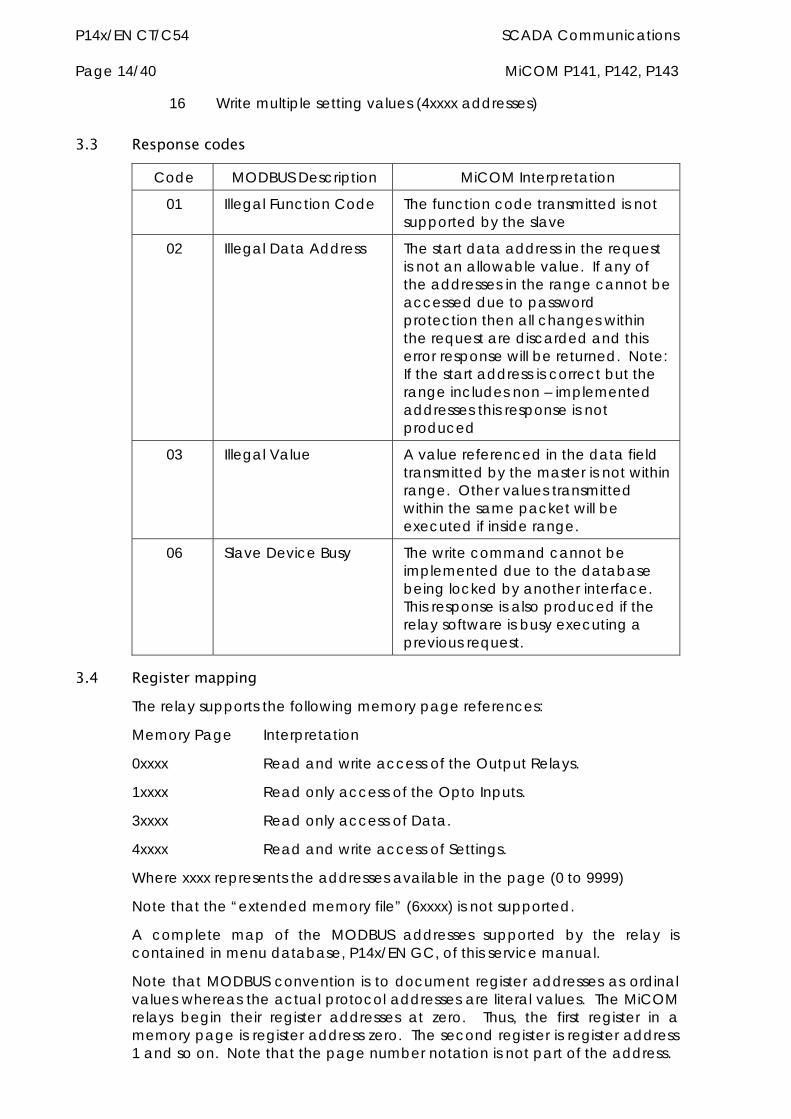
P14x/EN CT/C54 SCADA Communications Page 14/40 MiCOM P141, P142, P143
16 Write multiple setting values (4xxxx addresses)
3.3 Response codes
Code MODBUS Description MiCOM Interpretation
01 Illegal Function Code The function code transmitted is not supported by the slave
02 Illegal Data Address The start data address in the request is not an allowable value. If any of the addresses in the range cannot be accessed due to password protection then all changes within the request are discarded and this error response will be returned. Note: If the start address is correct but the range includes non – implemented addresses this response is not produced
03 Illegal Value A value referenced in the data field transmitted by the master is not within range. Other values transmitted within the same packet will be executed if inside range.
06 Slave Device Busy The write command cannot be implemented due to the database being locked by another interface. This response is also produced if the relay software is busy executing a previous request.
3.4 Register mapping The relay supports the following memory page references:
Memory Page Interpretation
0xxxx Read and write access of the Output Relays.
1xxxx Read only access of the Opto Inputs.
3xxxx Read only access of Data.
4xxxx Read and write access of Settings.
Where xxxx represents the addresses available in the page (0 to 9999)
Note that the “extended memory file” (6xxxx) is not supported.
A complete map of the MODBUS addresses supported by the relay is contained in menu database, P14x/EN GC, of this service manual.
Note that MODBUS convention is to document register addresses as ordinal values whereas the actual protocol addresses are literal values. The MiCOM relays begin their register addresses at zero. Thus, the first register in a memory page is register address zero. The second register is register address 1 and so on. Note that the page number notation is not part of the address.
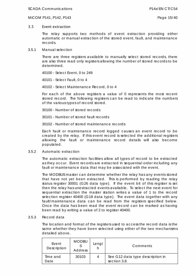
SCADA Communications P14x/EN CT/C54 MiCOM P141, P142, P143 Page 15/40
3.5 Event extraction The relay supports two methods of event extraction providing either automatic or manual extraction of the stored event, fault, and maintenance records.
3.5.1 Manual selection
There are three registers available to manually select stored records, there are also three read only registers allowing the number of stored records to be determined.
40100 - Select Event, 0 to 249
40101 - Select Fault, 0 to 4
40102 - Select Maintenance Record, 0 to 4
For each of the above registers a value of 0 represents the most recent stored record. The following registers can be read to indicate the numbers of the various types of record stored.
30100 - Number of stored records
30101 - Number of stored fault records
30102 - Number of stored maintenance records
Each fault or maintenance record logged causes an event record to be created by the relay. If this event record is selected the additional registers allowing the fault or maintenance record details will also become populated.
3.5.2 Automatic extraction
The automatic extraction facilities allow all types of record to be extracted as they occur. Event records are extracted in sequential order including any fault or maintenance data that may be associated with the event.
The MODBUS master can determine whether the relay has any events stored that have not yet been extracted. This is performed by reading the relay status register 30001 (G26 data type). If the event bit of this register is set then the relay has unextracted events available. To select the next event for sequential extraction the master station writes a value of 1 to the record selection register 40400 (G18 data type). The event data together with any fault/maintenance data can be read from the registers specified below. Once the data has been read the event record can be marked as having been read by writing a value of 2 to register 40400.
3.5.3 Record data
The location and format of the registers used to access the record data is the same whether they have been selected using either of the two mechanisms detailed above.
Event Description
MODBUS
Address
Length Comments
Time and Date
30103 4 See G12 data type description in section 3.8.
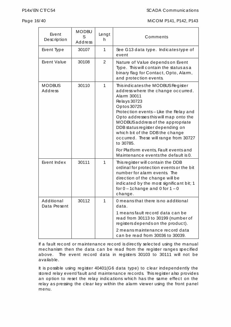
P14x/EN CT/C54 SCADA Communications Page 16/40 MiCOM P141, P142, P143
Event Description
MODBUS
Address
Length Comments
Event Type 30107 1 See G13 data type. Indicates type of event
Event Value 30108 2 Nature of Value depends on Event Type. This will contain the status as a binary flag for Contact, Opto, Alarm, and protection events.
MODBUS Address
30110 1 This indicates the MODBUS Register address where the change occurred. Alarm 30011 Relays 30723 Optos 30725 Protection events – Like the Relay and Opto addresses this will map onto the MODBUS address of the appropriate DDB status register depending on which bit of the DDB the change occurred. These will range from 30727 to 30785. For Platform events, Fault events and Maintenance events the default is 0.
Event Index 30111 1 This register will contain the DDB ordinal for protection events or the bit number for alarm events. The direction of the change will be indicated by the most significant bit; 1 for 0 – 1change and 0 for 1 – 0 change.
Additional Data Present
30112 1 0 means that there is no additional data. 1 means fault record data can be read from 30113 to 30199 (number of registers depends on the product). 2 means maintenance record data can be read from 30036 to 30039.
If a fault record or maintenance record is directly selected using the manual mechanism then the data can be read from the register ranges specified above. The event record data in registers 30103 to 30111 will not be available.
It is possible using register 40401(G6 data type) to clear independently the stored relay event/fault and maintenance records. This register also provides an option to reset the relay indications which has the same effect on the relay as pressing the clear key within the alarm viewer using the front panel menu.
SCADA Communications P14x/EN CT/C54 MiCOM P141, P142, P143 Page 17/40
3.6 Disturbance record extraction The relay provides facilities for both manual and automatic extraction of disturbance records. The extraction mechanisms are explained below:
3.6.1 Extraction mechanism
Records extracted over MODBUS from Px40 platform relays will be presented in COMTRADE format. This involves extracting an ASCII text configuration file and then extracting a binary data file.
Each file is extracted by reading a series of data pages from the relay. The data page is made up of 127 registers, giving a maximum transfer of 254 bytes per page.
3.6.1.1 Interface registers
The following set of registers is presented to the master station to support the extraction of uncompressed disturbance records:
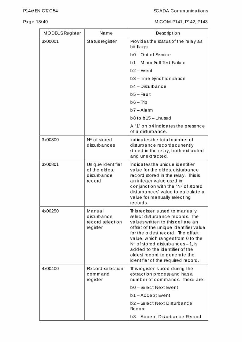
P14x/EN CT/C54 SCADA Communications Page 18/40 MiCOM P141, P142, P143
MODBUS Register Name Description
3x00001 Status register Provides the status of the relay as bit flags:
b0 – Out of Service
b1 – Minor Self Test Failure
b2 – Event
b3 – Time Synchronization
b4 – Disturbance
b5 – Fault
b6 – Trip
b7 – Alarm
b8 to b15 – Unused
A ‘1’ on b4 indicates the presence of a disturbance.
3x00800 No of stored disturbances
Indicates the total number of disturbance records currently stored in the relay, both extracted and unextracted.
3x00801 Unique identifier of the oldest disturbance record
Indicates the unique identifier value for the oldest disturbance record stored in the relay. This is an integer value used in conjunction with the ‘No of stored disturbances’ value to calculate a value for manually selecting records.
4x00250 Manual disturbance record selection register
This register is used to manually select disturbance records. The values written to this cell are an offset of the unique identifier value for the oldest record. The offset value, which ranges from 0 to the No of stored disturbances – 1, is added to the identifier of the oldest record to generate the identifier of the required record.
4x00400 Record selection command register
This register is used during the extraction process and has a number of commands. These are:
b0 – Select Next Event
b1 – Accept Event
b2 – Select Next Disturbance Record
b3 – Accept Disturbance Record
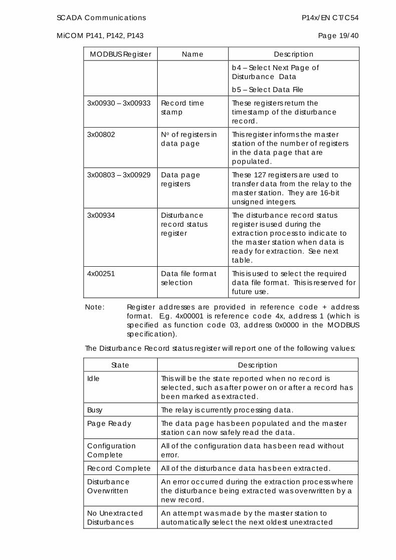
SCADA Communications P14x/EN CT/C54 MiCOM P141, P142, P143 Page 19/40
MODBUS Register Name Description
b4 – Select Next Page of Disturbance Data
b5 – Select Data File
3x00930 – 3x00933 Record time stamp
These registers return the timestamp of the disturbance record.
3x00802 No of registers in data page
This register informs the master station of the number of registers in the data page that are populated.
3x00803 – 3x00929 Data page registers
These 127 registers are used to transfer data from the relay to the master station. They are 16-bit unsigned integers.
3x00934 Disturbance record status register
The disturbance record status register is used during the extraction process to indicate to the master station when data is ready for extraction. See next table.
4x00251 Data file format selection
This is used to select the required data file format. This is reserved for future use.
Note: Register addresses are provided in reference code + address format. E.g. 4x00001 is reference code 4x, address 1 (which is specified as function code 03, address 0x0000 in the MODBUS specification).
The Disturbance Record status register will report one of the following values:
State Description
Idle This will be the state reported when no record is selected, such as after power on or after a record has been marked as extracted.
Busy The relay is currently processing data.
Page Ready The data page has been populated and the master station can now safely read the data.
Configuration Complete
All of the configuration data has been read without error.
Record Complete All of the disturbance data has been extracted.
Disturbance Overwritten
An error occurred during the extraction process where the disturbance being extracted was overwritten by a new record.
No Unextracted Disturbances
An attempt was made by the master station to automatically select the next oldest unextracted
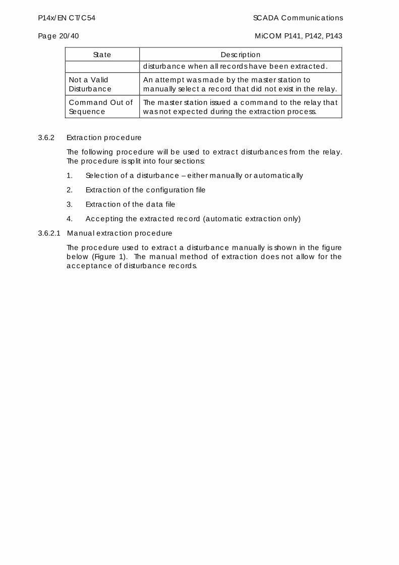
P14x/EN CT/C54 SCADA Communications Page 20/40 MiCOM P141, P142, P143
State Description disturbance when all records have been extracted.
Not a Valid Disturbance
An attempt was made by the master station to manually select a record that did not exist in the relay.
Command Out of Sequence
The master station issued a command to the relay that was not expected during the extraction process.
3.6.2 Extraction procedure
The following procedure will be used to extract disturbances from the relay. The procedure is split into four sections:
1. Selection of a disturbance – either manually or automatically
2. Extraction of the configuration file
3. Extraction of the data file
4. Accepting the extracted record (automatic extraction only)
3.6.2.1 Manual extraction procedure
The procedure used to extract a disturbance manually is shown in the figure below (Figure 1). The manual method of extraction does not allow for the acceptance of disturbance records.
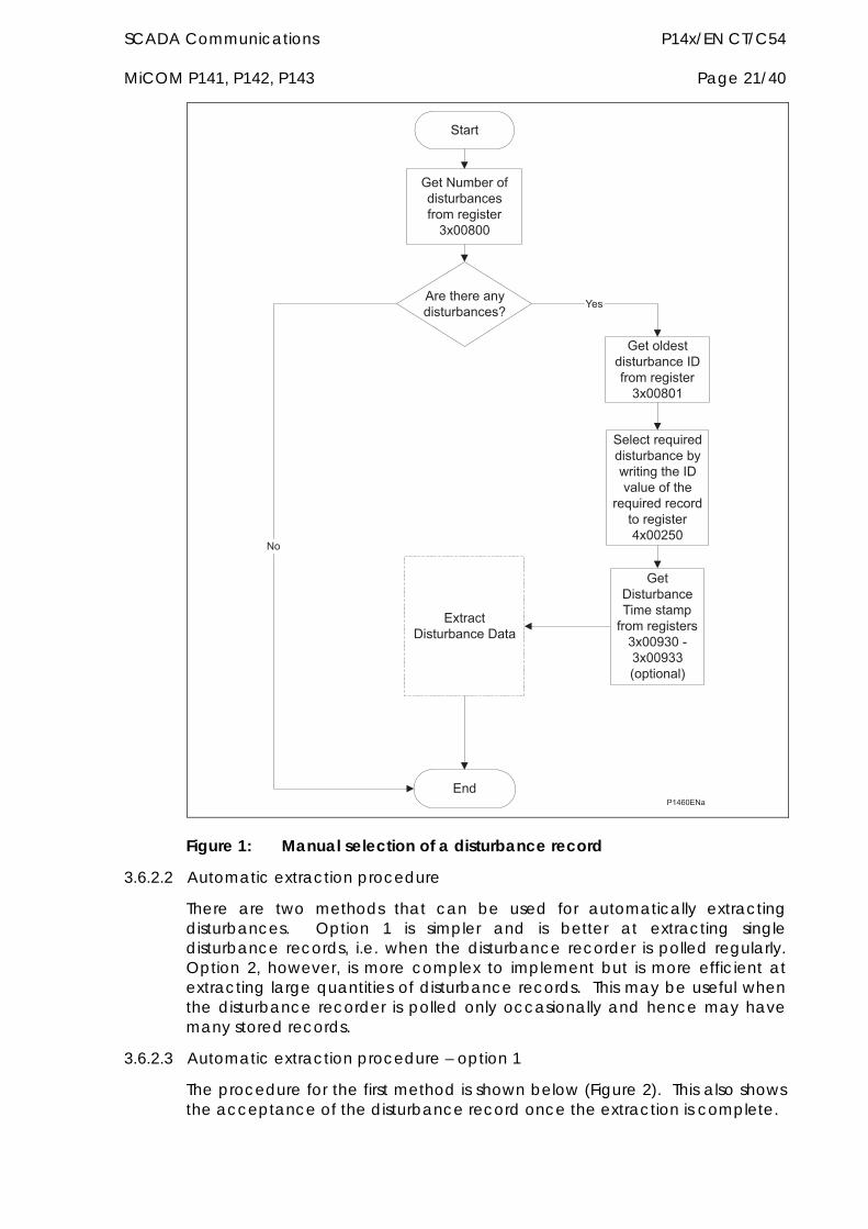
SCADA Communications P14x/EN CT/C54 MiCOM P141, P142, P143 Page 21/40
�����
��������� �������������� �����������������
�������������������������
���� �������������������� ����������������
!���������������������
!��
���������"�����������������#�������������$���� �����
��"�������� ��� ���������%���&'�
�������������(��������)�� ���������������*���+����*��, )�� ���-
.��
�������
Figure 1: Manual selection of a disturbance record
3.6.2.2 Automatic extraction procedure
There are two methods that can be used for automatically extracting disturbances. Option 1 is simpler and is better at extracting single disturbance records, i.e. when the disturbance recorder is polled regularly. Option 2, however, is more complex to implement but is more efficient at extracting large quantities of disturbance records. This may be useful when the disturbance recorder is polled only occasionally and hence may have many stored records.
3.6.2.3 Automatic extraction procedure – option 1
The procedure for the first method is shown below (Figure 2). This also shows the acceptance of the disturbance record once the extraction is complete.
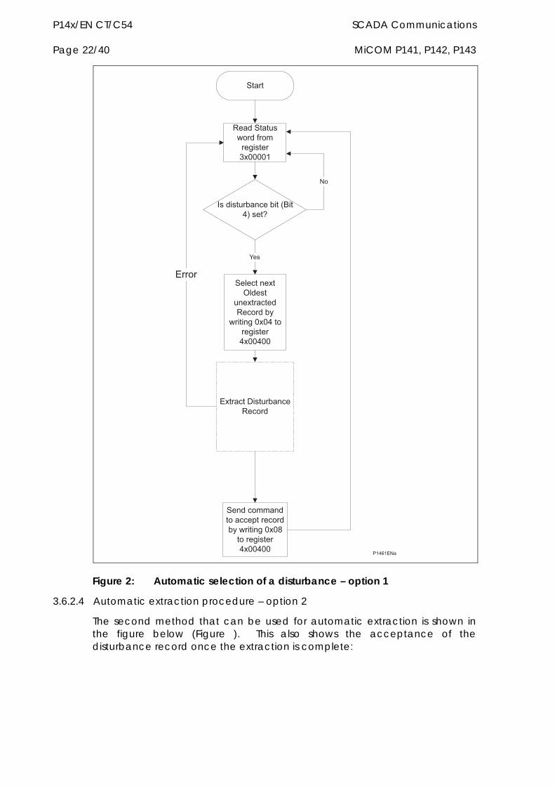
P14x/EN CT/C54 SCADA Communications Page 22/40 MiCOM P141, P142, P143
�������
�����
/���������# ����� ���������������
������������������,0��%-�����
.��
�����������1�����
����������/�� �����
#����������%�� ��������%���%��
������ ������ �����)����� �����#������������ ���������%���%��
!�����������������/�� ��
!�� �
Figure 2: Automatic selection of a disturbance – option 1
3.6.2.4 Automatic extraction procedure – option 2
The second method that can be used for automatic extraction is shown in the figure below (Figure ). This also shows the acceptance of the disturbance record once the extraction is complete:
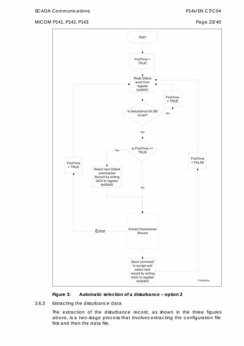
SCADA Communications P14x/EN CT/C54 MiCOM P141, P142, P143 Page 23/40
������
�����
/���������# ����� ���������������
������������������,0��%-�����
.��
������������1���������������
/�� ������#���������%�� ���������
%���%��
������ ������ �����)����������������
��� ������#���������2�� ���������
%���%��
!�����������������/�� ��
3����(����4(/5!
3����(���4�(/5!
���3����(����44(/5!
.��
3����(���4�3�6�!3����(���
4�(/5!
!�� �
Figure 3: Automatic selection of a disturbance – option 2
3.6.3 Extracting the disturbance data
The extraction of the disturbance record, as shown in the three figures above, is a two-stage process that involves extracting the configuration file first and then the data file.
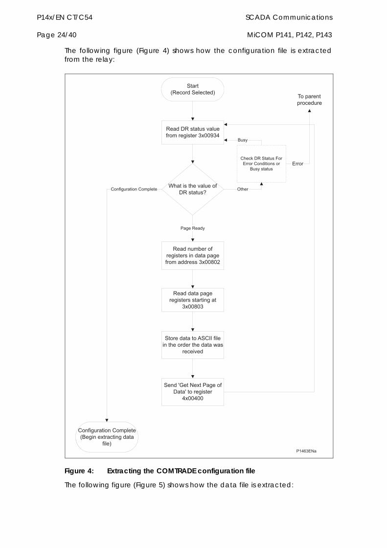
P14x/EN CT/C54 SCADA Communications Page 24/40 MiCOM P141, P142, P143
The following figure (Figure 4) shows how the configuration file is extracted from the relay:
�������
�����,/�� �����������-
/�����/�������$����� ���������������*�%
7�����������$���� ��/�������
/���������� �������������������)����� ����������������&
8����/����
/���������)������������������������
�������
�� ��������� ���2�������������� ��������������#��
�����$��
�����9��������8���� �����9�� ���������
%���%��
2 �������� ��2 �)����
2 �������� ��2 �)����,0��������������������
����-
1����
2���:��/�������3 �!�� ��2 ����� ��� �
0��������
0��
!�� �
( �)�����)� �����
Figure 4: Extracting the COMTRADE configuration file
The following figure (Figure 5) shows how the data file is extracted:
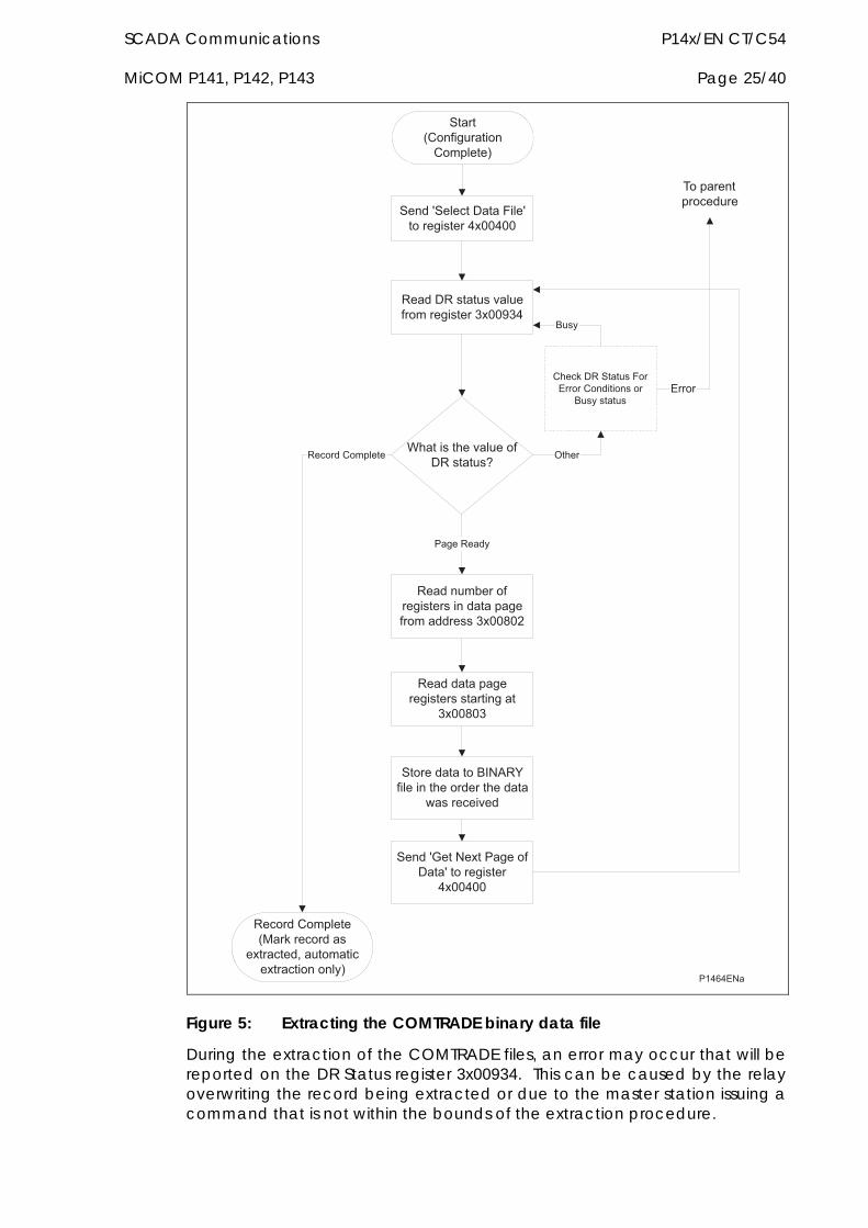
SCADA Communications P14x/EN CT/C54 MiCOM P141, P142, P143 Page 25/40
�������
�����,2 �������� �2 �)����-
/�����/�������$����� ���������������*�%
7�����������$���� ��/�������
/���������� �������������������)����� ����������������&
8����/����
/���������)������������������������
�������
�� ��������� �0��/.������������ �������������
#��������$��
�����9��������8���� �����9�� ���������
%���%��
/�� ���2 �)����
/�� ���2 �)����,;��:���� �����
���������<��� ������������� �� ���-
1����
2���:��/�������3 �!�� ��2 ����� ��� �
0��������
0��
�����9������������3���9� ����������%���%��
!�� �
( �)�����)� �����
Figure 5: Extracting the COMTRADE binary data file
During the extraction of the COMTRADE files, an error may occur that will be reported on the DR Status register 3x00934. This can be caused by the relay overwriting the record being extracted or due to the master station issuing a command that is not within the bounds of the extraction procedure.
P14x/EN CT/C54 SCADA Communications Page 26/40 MiCOM P141, P142, P143
3.7 Setting changes The relay settings can be split into two categories:
control and support settings
disturbance record settings and protection setting groups
Changes to settings within the control and support area are executed immediately. Changes to the protection setting groups or the disturbance recorder settings are stored in a temporary ‘scratchpad’ area and must be confirmed before they are implemented. All the relay settings are 4xxxx page addresses. The following points should be noted when changing settings:
Settings implemented using multiple registers must be written to using a multi-register write operation.
The first address for a multi-register write must be a valid address, if there are unmapped addresses within the range being written to then the data associated with these addresses will be discarded.
If a write operation is performed with values that are out of range then the illegal data response will be produced. Valid setting values within the same write operation will be executed.
If a write operation is performed attempting to change registers that require a higher level of password access than is currently enabled then all setting changes in the write operation will be discarded.
3.7.1 Password protection
As described in the introduction to this service manual, the relay settings can be subject to Password protection. The level of password protection required to change a setting is indicated in the relay setting database (P14x/EN GC). Level 2 is the highest level of password access, level 0 indicates that no password is required.
The following registers are available to control Password protection:
40001&40002 Password Entry
40022 Default Password Level
40023&40024 Setting to Change password level 1
40025&40026 Setting to Change password level 2
30010 Can be read to indicate current access level
3.7.2 Control and support settings
Control and support settings are executed immediately on the write operation.
3.7.3 Protection and disturbance recorder settings
Setting changes to either of these areas are stored in a scratchpad area and will not be used by the relay unless a confirm or an abort operation is performed. Register 40405 can be used either to confirm or abort the setting changes within the scratchpad area. It should be noted that the relay

SCADA Communications P14x/EN CT/C54 MiCOM P141, P142, P143 Page 27/40
supports four groups of protection settings. The MODBUS addresses for each of the four groups are repeated within the following address ranges:
Group 1 41000-42999
Group 2 43000-44999
Group 3 45000-46999
Group 4 47000-48999
In addition to the basic editing of the protection setting groups, the following functions are provided:
Default values can be restored to a setting group or to all of the relay settings by writing to register 40402.
It is possible to copy the contents of one setting group to another by writing the source group to register 40406 and the target group to 40407.
It should be noted that the setting changes performed by either of the two operations defined above are made to the scratchpad area. These changes must be confirmed by writing to register 40405.
The active protection setting groups can be selected by writing to register 40404. An illegal data response will be returned if an attempt is made to set the active group to one that has been disabled.
3.8 Date and time format (data type G12) The date-time data type G12 allows real date and time information to be conveyed down to a resolution of 1ms. The structure of the data type is shown in Table 3-1 and is compliant with the IEC60870-5-4 “Binary Time 2a” format.
The seven bytes of the structure are packed into four 16-bit registers, such that byte 1 is transmitted first, followed by byte 2 through to byte 7, followed by a null (zero) byte to make eight bytes in total. Since register data is usually transmitted in big-endian format (high order byte followed by low order byte), byte 1 will be in the high-order byte position followed by byte 2 in the low-order position for the first register. The last register will contain just byte 7 in the high order position and the low order byte will have a value of zero.
Bit Position Byte
7 6 5 4 3 2 1 0
1 m7 m6 m5 m4 m3 m2 m1 m0
2 m15 m14 m13 m12 m11 m10 m9 m8
3 IV R I5 I4 I3 I2 I1 I0
4 SU R R H4 H3 H2 H1 H0
5 W2 W1 W0 D4 D3 D2 D1 D0
6 R R R R M3 M2 M1 M0
7 R Y6 Y5 Y4 Y3 Y2 Y1 Y0
P14x/EN CT/C54 SCADA Communications Page 28/40 MiCOM P141, P142, P143
Where:
m = 0…59,999ms
I = 0…59 minutes
H = 0…23 Hours
W = 1…7 Day of week; Monday to Sunday, 0 for not calculated
D = 1…31 Day of Month
M = 1…12 Month of year; January to December
Y = 0…99 Years (year of century)
R = Reserved bit = 0
SU = summertime: 0=standard time, 1=summer time
IV = invalid value: 0=valid, 1=invalid
range = 0ms…99 years
Table 3-1 G12 Date & time data type structure
Since the range of the data type is only 100 years, the century must be deduced. The century is calculated as the one that will produce the nearest time value to the current date. For example: 30-12-99 is 30-12-1999 when received in 1999 & 2000, but is 30-12-2099 when received in 2050. This technique allows 2 digit years to be accurately converted to 4 digits in a ±50 year window around the current datum.
The invalid bit has two applications:
1. It can indicate that the date-time information is considered inaccurate, but is the best information available.
2. Date-time information is not available.
The summertime bit is used to indicate that summertime (day light saving) is being used and, more importantly, to resolve the alias and time discontinuity which occurs when summertime starts and ends. This is important for the correct time correlation of time stamped records.
The day of the week field is optional and if not calculated will be set to zero.
The concept of time zone is not catered for by this data type and hence by the relay. It is up to the end user to determine the time zone utilised by the relay. Normal practise is to use UTC (universal co-ordinated time), which avoids the complications with day light saving time-stamp correlation’s.
3.9 Power & energy measurement data formats (G29 & G125) The power and energy measurements are available in two data formats; G29 integer format and G125 IEEE754 floating point format. For historical reasons the registers listed in the main part of the “Measurements 2” column of the menu database (see P14x/EN GC) are of the G29 format. The floating point, G125, versions appear at the end of the column.
SCADA Communications P14x/EN CT/C54 MiCOM P141, P142, P143 Page 29/40
3.9.1 Data type G29
Data type G29 consists of three registers. The first register is the per unit power or energy measurement and is of type G28, which is a signed 16 bit quantity. The second and third registers contain a multiplier to convert the per unit value to a real value. The multiplier is of type G27, which is an unsigned 32-bit quantity. Thus, the overall value conveyed by the G29 data type must be calculated as G29=G28G27.
The relay calculates the G28 per unit power or energy value as G28=((measured secondary quantity) / (CT secondary) (110V / (VT secondary)). Since data type G28 is a signed 16-bit integer, its dynamic range is constrained to ±32768. This limitation should be borne in mind for the energy measurements, as the G29 value will saturate a long time before the equivalent G125 does.
The associated G27 multiplier is calculated as G27=(CT primary) (VT primary / 110V) when primary value measurements are selected, and as G27=(CT secondary) (VT secondary / 110V) when secondary value measurements are selected.
Due to the required truncations from floating point values to integer values in the calculations of the G29 component parts and its limited dynamic range, the use of the G29 values is only recommended when the MODBUS master cannot deal with the G125 IEEE754 floating point equivalents.
Note that the G29 values must be read in whole multiples of three registers. It is not possible to read the G28 and G27 parts with separate read commands.
Example:
For A-Phase Power (Watts) (registers 30300 - 30302) for a 110V relay, In = 1A, VT ratio = 110V:110V and CT ratio = 1A:1A.
Applying A-phase 1A @ 63.51V
A-phase Watts = ((63.51V 1A) / In=1A) (110/Vn=110V) = 63.51 Watts
The G28 part of the value is the truncated per unit quantity, which will be equal to 64 (40h).
The multiplier is derived from the VT and CT ratios set in the relay, with the equation ((CT Primary) (VT Primary) / 110V). Thus, the G27 part of the value will equal 1. Hence the overall value of the G29 register set is 641 = 64W
The registers would contain:
30300 - 0040h
30301 - 0000h
30302 - 0001h
Using the previous example with a VT ratio = 110,000V:110V and CT ratio = 10,000A:1A the G27 multiplier would be 10,000A110,000V/110 = 10,000,000. The overall value of the G29 register set is 64 10,000,000 = 640MW. (Note that there is an actual error of 49MW in this calculation due to loss of resolution.)
The registers would contain:
P14x/EN CT/C54 SCADA Communications Page 30/40 MiCOM P141, P142, P143
30300 - 0040h
30301 - 0098h
30302 - 9680h
3.9.2 Data type G125
Data type G125 is a short float IEEE754 floating point format, which occupies 32 bits in two consecutive registers. The high order byte of the format is in the first (low order) register and the low order byte in the second register.
The value of the G125 measurement is as accurate as the relay’s ability to resolve the measurement after it has applied the secondary or primary scaling factors as require. It does not suffer from the truncation errors or dynamic range limitations associated with the G29 data format.
SCADA Communications P14x/EN CT/C54 MiCOM P141, P142, P143 Page 31/40
4 IEC60870-5-103 interface The IEC60870-5-103 interface is a master/slave interface with the relay as the slave device. The relay conforms to compatibility level 2, compatibility level 3 is not supported.
The following IEC60870-5-103 facilities are supported by this interface:
Initialisation (Reset)
Time Synchronisation
Event Record Extraction
General Interrogation
Cyclic Measurements
General Commands
Disturbance Record Extraction
Private Codes
4.1 Physical connection and link layer Two connection options are available for IEC60870-5-103, either the rear EIA(RS)485 port or an optional rear fibre optic port. Should the fibre optic port be fitted the selection of the active port can be made via the front panel menu or the front Courier port, however the selection will only be effective following the next relay power up.
For either of the two modes of connection it is possible to select both the relay address and baud rate using the front panel menu/front Courier. Following a change to either of these two settings a reset command is required to re-establish communications, see reset command description below.
4.2 Initialisation Whenever the relay has been powered up, or if the communication parameters have been changed a reset command is required to initialise the communications. The relay will respond to either of the two reset commands (Reset CU or Reset FCB), the difference being that the Reset CU will clear any unsent messages in the relay’s transmit buffer.
The relay will respond to the reset command with an identification message ASDU 5, the Cause Of Transmission COT of this response will be either Reset CU or Reset FCB depending on the nature of the reset command. The content of ASDU 5 is described in the IEC60870-5-103 section of the menu database, P14x/EN GC.
In addition to the above identification message, if the relay has been powered up it will also produce a power up event.
4.3 Time synchronisation The relay time and date can be set using the time synchronisation feature of the IEC60870-5-103 protocol. The relay will correct for the transmission delay
P14x/EN CT/C54 SCADA Communications Page 32/40 MiCOM P141, P142, P143
as specified in IEC60870-5-103. If the time synchronisation message is sent as a send/confirm message then the relay will respond with a confirm. Whether the time-synchronisation message is sent as a send confirm or a broadcast (send/no reply) message, a time synchronisation Class 1 event will be generated/produced.
If the relay clock is being synchronised using the IRIG-B input then it will not be possible to set the relay time using the IEC60870-5-103 interface. An attempt to set the time via the interface will cause the relay to create an event with the current date and time taken from the IRIG-B synchronised internal clock.
4.4 Spontaneous events Events are categorised using the following information:
Function Type
Information number
The IEC60870-5-103 profile in the menu database, P14x/EN GC, contains a complete listing of all events produced by the relay.
4.5 General interrogation The GI request can be used to read the status of the relay, the function numbers, and information numbers that will be returned during the GI cycle are indicated in the IEC60870-5-103 profile in the menu database, P14x/EN GC.
4.6 Cyclic measurements The relay will produce measured values using ASDU 9 on a cyclical basis, this can be read from the relay using a Class 2 poll (note ADSU 3 is not used). The rate at which the relay produces new measured values can be controlled using the Measurement Period setting. This setting can be edited from the front panel menu/front Courier port and is active immediately following a change.
It should be noted that the measurands transmitted by the relay are sent as a proportion of 2.4 times the rated value of the analogue value.
4.7 Commands A list of the supported commands is contained in the menu database, P14x/EN GC. The relay will respond to other commands with an ASDU 1, with a cause of transmission (COT) indicating ‘negative acknowledgement’.
4.8 Test mode It is possible using either the front panel menu or the front Courier port to disable the relay output contacts to allow secondary injection testing to be performed. This is interpreted as ‘test mode’ by the IEC60870-5-103 standard. An event will be produced to indicate both entry to and exit from test mode. Spontaneous events and cyclic measured data transmitted whilst the relay is in test mode will have a COT of ‘test mode’.

SCADA Communications P14x/EN CT/C54 MiCOM P141, P142, P143 Page 33/40
4.9 Disturbance records The disturbance records are stored in uncompressed format and can be extracted using the standard mechanisms described in IEC60870-5-103. Note, IEC60870-5-103 only supports up to 8 records.
4.10 Blocking of monitor direction The relay supports a facility to block messages in the Monitor direction and also in the Command direction. Messages can be blocked in the Monitor and Command directions using the menu commands, Communications – CS103 Blocking – Disabled/Monitor Blocking/Command Blocking or DDB signals Monitor Blocked and Command Blocked.
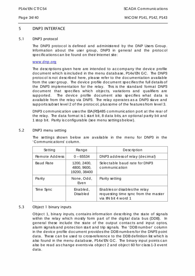
P14x/EN CT/C54 SCADA Communications Page 34/40 MiCOM P141, P142, P143
5 DNP3 INTERFACE
5.1 DNP3 protocol The DNP3 protocol is defined and administered by the DNP Users Group. Information about the user group, DNP3 in general and the protocol specifications can be found on their Internet site:
www.dnp.org
The descriptions given here are intended to accompany the device profile document which is included in the menu database, P14x/EN GC. The DNP3 protocol is not described here, please refer to the documentation available from the user group. The device profile document specifies the full details of the DNP3 implementation for the relay. This is the standard format DNP3 document that specifies which objects, variations and qualifiers are supported. The device profile document also specifies what data is available from the relay via DNP3. The relay operates as a DNP3 slave and supports subset level 2 of the protocol, plus some of the features from level 3.
DNP3 communication uses the EIA(RS)485 communication port at the rear of the relay. The data format is 1 start bit, 8 data bits, an optional parity bit and 1 stop bit. Parity is configurable (see menu settings below).
5.2 DNP3 menu setting The settings shown below are available in the menu for DNP3 in the ‘Communications’ column.
Setting Range Description
Remote Address 0 – 65534 DNP3 address of relay (decimal)
Baud Rate 1200, 2400, 4800, 9600,
19200, 38400
Selectable baud rate for DNP3 communication
Parity None, Odd, Even
Parity setting
Time Sync Enabled, Disabled
Enables or disables the relay requesting time sync from the master via IIN bit 4 word 1
5.3 Object 1 binary inputs Object 1, binary inputs, contains information describing the state of signals within the relay which mostly form part of the digital data bus (DDB). In general these include the state of the output contacts and input optos, alarm signals and protection start and trip signals. The ‘DDB number’ column in the device profile document provides the DDB numbers for the DNP3 point data. These can be used to cross-reference to the DDB definition list which is also found in the menu database, P14x/EN GC. The binary input points can also be read as change events via object 2 and object 60 for class 1-3 event data.
SCADA Communications P14x/EN CT/C54 MiCOM P141, P142, P143 Page 35/40
5.4 Object 10 binary outputs Object 10, binary outputs, contains commands which can be operated via DNP3. As such the points accept commands of type pulse on [null, trip, close] and latch on/off as detailed in the device profile in the menu database, P14x/EN GC and execute the command once for either command. The other fields are ignored (queue, clear, trip/close, in time and off time).
Due to that fact that many of the relay’s functions are configurable, it may be the case that some of the object 10 commands described below are not available for operation. In the case of a read from object 10 this will result in the point being reported as off-line and an operate command to object 12 will generate an error response.
Examples of object 10 points that maybe reported as off-line are:
Activate setting groups - Ensure setting groups are enabled
CB trip/close - Ensure remote CB control is enabled
Reset NPS thermal - Ensure NPS thermal protection is enabled
Reset thermal O/L - Ensure thermal overload protection is enabled
Reset RTD flags - Ensure RTD Inputs is enabled
Control Inputs - Ensure control inputs are enabled
5.5 Object 20 binary counters Object 20, binary counters, contains cumulative counters and measurements. The binary counters can be read as their present ‘running’ value from object 20, or as a ‘frozen’ value from object 21. The running counters of object 20 accept the read, freeze and clear functions. The freeze function takes the current value of the object 20 running counter and stores it in the corresponding object 21 frozen counter. The freeze and clear function resets the object 20 running counter to zero after freezing its value.
5.6 Object 30 analogue input Object 30, analogue inputs, contains information from the relay’s measurements columns in the menu. All object 30 points are reported as fixed-point values although they are stored inside the relay in a floating point format. The conversion to fixed point format requires the use of a scaling factor, which differs for the various types of data within the relay e.g. current, voltage, phase angle etc. The data types supported are listed at the end of the device profile document with each type allocated a ‘D number’, i.e. D1, D2, etc. In the object 30 point list each data point has a D number data type assigned to it which defines the scaling factor, default deadband setting and the range and resolution of the deadband setting. The deadband is the setting used to determine whether a change event should be generated for each point. The change events can be read via object 32 or object 60 and will be generated for any point whose value has changed by more than the deadband setting since the last time the data value was reported.
P14x/EN CT/C54 SCADA Communications Page 36/40 MiCOM P141, P142, P143
Any analogue measurement that is unavailable at the time it is read will be reported as offline, e.g. the frequency when the current and voltage frequency is outside the tracking range of the relay or the thermal state when the thermal protection is disabled in the configuration column. Note that all object 30 points are reported as secondary values in DNP3 (with respect to CT and VT ratios).
5.7 DNP3 configuration using MiCOM S1 A PC support package for DNP3 is available as part of the Settings and Records module of MiCOM S1. The S1 module allows configuration of the relay’s DNP3 response. The PC is connected to the relay via a serial cable to the 9-pin front part of the relay – see Introduction (P14x/EN IT). The configuration data is uploaded from the relay to the PC in a block of compressed format data and downloaded to the relay in a similar manner after modification. The new DNP3 configuration takes effect in the relay after the download is complete. The default configuration can be restored at any time by choosing ‘All Settings’ from the ‘Restore Defaults’ cell in the menu ‘Configuration’ column. In S1, the DNP3 data is displayed on a three tabbed screen, one screen each for object1, 20 and 30. Object 10 is not configurable.
5.7.1 Object 1
For every point included in the device profile document there is a check box for membership of class 0 and radio buttons for class 1, 2 or 3 membership. Any point that is in class 0 must be a member of one of the change event classes 1, 2 or 3.
Points that are configured out of class 0 are by default not capable of generating change events. Furthermore, points that are not part of class 0 are effectively removed from the DNP3 response by renumbering the points that are in class 0 into a contiguous list starting at point number 0. The renumbered point numbers are shown at the left hand side of the screen in S1 and can be printed out to form a revised device profile for the relay. This mechanism allows best use of available bandwidth by only reporting the data points required by the user when a poll for all points is made.
5.7.2 Object 20
The running counter value of object 20 points can be configured to be in or out of class 0. Any running counter that is in class 0 can have its frozen value selected to be in or out of the DNP3 response, but a frozen counter cannot be included without the corresponding running counter. As with object 1, the class 0 response will be renumbered into a contiguous list of points based on the selection of running counters. The frozen counters will also be renumbered based on the selection; note that if some of the counters that are selected as running are not also selected as frozen then the renumbering will result in the frozen counters having different point numbers to their running counterparts. For example, object 20 point 3 (running counter) might have its frozen value reported as object 21 point 1.
5.7.3 Object 30
For the analogue inputs, object 30, the same selection options for classes 0, 1, 2 and 3 are available as for object 1. In addition to these options, which behave in exactly the same way as for object 1, it is possible to change the

SCADA Communications P14x/EN CT/C54 MiCOM P141, P142, P143 Page 37/40
deadband setting for each point. The minimum and maximum values and the resolution of the deadband settings are defined in the device profile document; MiCOM S1 will allow the deadband to be set to any value within these constraints.
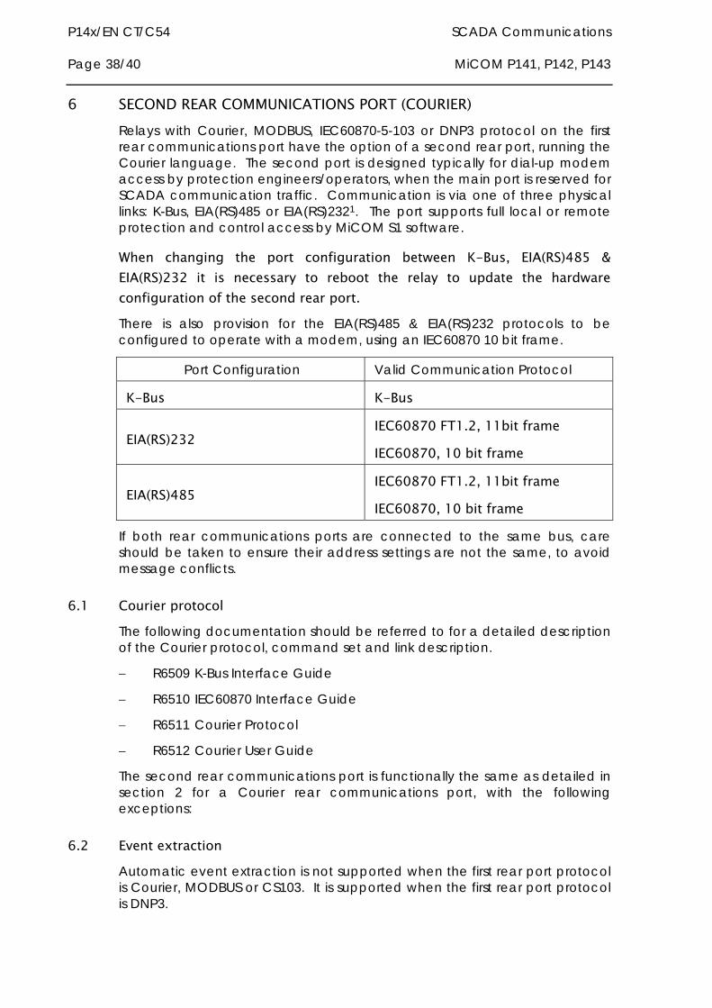
P14x/EN CT/C54 SCADA Communications Page 38/40 MiCOM P141, P142, P143
6 SECOND REAR COMMUNICATIONS PORT (COURIER) Relays with Courier, MODBUS, IEC60870-5-103 or DNP3 protocol on the first rear communications port have the option of a second rear port, running the Courier language. The second port is designed typically for dial-up modem access by protection engineers/operators, when the main port is reserved for SCADA communication traffic. Communication is via one of three physical links: K-Bus, EIA(RS)485 or EIA(RS)2321. The port supports full local or remote protection and control access by MiCOM S1 software.
When changing the port configuration between K-Bus, EIA(RS)485 & EIA(RS)232 it is necessary to reboot the relay to update the hardware configuration of the second rear port. There is also provision for the EIA(RS)485 & EIA(RS)232 protocols to be configured to operate with a modem, using an IEC60870 10 bit frame.
Port Configuration Valid Communication Protocol
K-Bus K-Bus
EIA(RS)232 IEC60870 FT1.2, 11bit frame
IEC60870, 10 bit frame
EIA(RS)485 IEC60870 FT1.2, 11bit frame
IEC60870, 10 bit frame
If both rear communications ports are connected to the same bus, care should be taken to ensure their address settings are not the same, to avoid message conflicts.
6.1 Courier protocol The following documentation should be referred to for a detailed description of the Courier protocol, command set and link description.
R6509 K-Bus Interface Guide
R6510 IEC60870 Interface Guide
R6511 Courier Protocol
R6512 Courier User Guide
The second rear communications port is functionally the same as detailed in section 2 for a Courier rear communications port, with the following exceptions:
6.2 Event extraction Automatic event extraction is not supported when the first rear port protocol is Courier, MODBUS or CS103. It is supported when the first rear port protocol is DNP3.
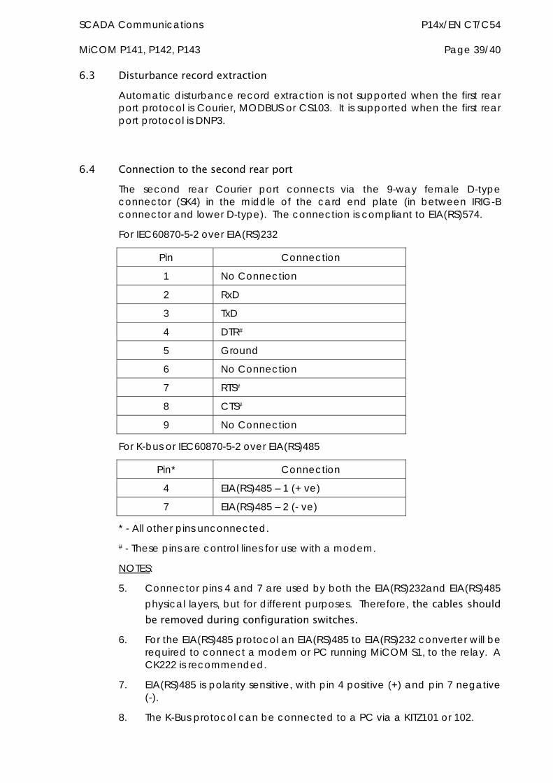
SCADA Communications P14x/EN CT/C54 MiCOM P141, P142, P143 Page 39/40
6.3 Disturbance record extraction Automatic disturbance record extraction is not supported when the first rear port protocol is Courier, MODBUS or CS103. It is supported when the first rear port protocol is DNP3.
6.4 Connection to the second rear port The second rear Courier port connects via the 9-way female D-type connector (SK4) in the middle of the card end plate (in between IRIG-B connector and lower D-type). The connection is compliant to EIA(RS)574.
For IEC60870-5-2 over EIA(RS)232
Pin Connection
1 No Connection
2 RxD
3 TxD
4 DTR#
5 Ground
6 No Connection
7 RTS#
8 CTS#
9 No Connection
For K-bus or IEC60870-5-2 over EIA(RS)485
Pin* Connection
4 EIA(RS)485 – 1 (+ ve)
7 EIA(RS)485 – 2 (- ve)
* - All other pins unconnected. # - These pins are control lines for use with a modem.
NOTES:
5. Connector pins 4 and 7 are used by both the EIA(RS)232and EIA(RS)485 physical layers, but for different purposes. Therefore, the cables should be removed during configuration switches.
6. For the EIA(RS)485 protocol an EIA(RS)485 to EIA(RS)232 converter will be required to connect a modem or PC running MiCOM S1, to the relay. A CK222 is recommended.
7. EIA(RS)485 is polarity sensitive, with pin 4 positive (+) and pin 7 negative (-).
8. The K-Bus protocol can be connected to a PC via a KITZ101 or 102.

P14x/EN CT/C54 SCADA Communications Page 40/40 MiCOM P141, P142, P143
7 SK5 PORT CONNECTION The lower 9-way D-type connector (SK5) is currently unsupported. Do not connect to this port.
UCA2.0 Communications P14x/EN UC/C54 MiCOM P141, P142, P143
UCA2.0 COMMUNICATIONS

P14x/EN UC/C54 UCA2.0 Communications MiCOM P141, P142, P143
UCA2.0 Communications P14x/EN UC/C54 MiCOM P141, P142, P143 Page 1/28
CONTENT
1. WHAT IS UCA2.0? 3
1.1 Why interoperability 3
1.2 What is GOMSFE? 3
1.3 How is UCA2.0 built up? 4
1.4 Summary 5
1.5 Example of a functional component 5
2. INTRODUCTION TO UCA2.0 GOOSE 7
2.1 UCA2.0 GOOSE message structure 7
2.2 UCA2.0 GOOSE message configuration 8
3. UCA2.0 IN MiCOM PX40 11
3.1 Capability 11
3.2 Network connectivity 12
3.3 Access to measurements 12
3.4 Settings 12 3.4.1 Remote setting management 12
3.4.2 Accessing settings and controls 12
3.4.3 UCA2.0 settings & statistics 13
3.4.4 UCA2.0 connection settings 13
4. UCA2.0 GOOSE IN PX40 15
4.1 UCA2.0 GOOSE configuration 15 4.1.1 Configuration overview 15
4.1.2 Virtual inputs 15
4.1.3 Virtual outputs 16
4.2 UCA2.0 GOOSE processing & pre-sets 16 4.2.1 Pre-processing 16
4.2.2 Post-processing 16
4.3 UCA2.0 GOOSE start-up modes 17
P14x/EN UC/C54 UCA2.0 Communications Page 2/28 MiCOM P141, P142, P143
4.3.1 Promiscuous start-up 17
4.3.2 Broadcast start-up 18
4.4 Ethernet hardware 18 4.4.1 Ethernet disconnection 18
4.4.2 Loss of power 19
5. P140 UCA2.0 DATA MODEL DESCRIPTION 20
5.1 Data model overview 20
5.2 Device identity 25
5.3 Wrapper glossary 26
Figure 1: Data representation over UCA2.0 4
Figure 2: GOOSE message transmission rates 9
UCA2.0 Communications P14x/EN UC/C54 MiCOM P141, P142, P143 Page 3/28
1. WHAT IS UCA2.0? UCA2.0 is a communication architecture that was created by the Electric Power Research Institute (EPRI) as a generic means of representing information for use across the electric and other utility industries.
In the late 1980’s, the evolving presence of numerical technology, digital processing and computing brought a much greater efficiency and operational potential to the electric utilities. Products were utilising communication protocols best suited to the Protection & Control industry; little thought was given to the ease of integration of these products with other vendors’ products and systems. The result of which was costly and confusing for Engineers to integrate.
In response to this problem, and foreseeing the advantages to both utilities and vendors, EPRI began the Integrated Utility Communications (IUC) program. The goal was the creation of a set of industry standards applicable to all utility industries. One of the first projects, UCA2.0 was concerned with defining the methods and language that would allow devices from different vendors to understand each other, or interoperate.
It is important to note that UCA2.0 is an architecture, rather than a simple protocol, UCA2.0 incorporates a family of basic communications protocols. The selection and organisation of these protocols has been designed to provide great flexibility, and to reduce integration and vendor product costs.
1.1 Why interoperability UCA2.0 responds to the utilities’ desire of having easier integration for different vendors’ products. Traditionally, one vendor’s implementation of MODBUS, for example, could place the A phase amps at register 40002. Other devices on the network, such as a Remote Terminal Unit (RTU), would then be programmed with the location of this information. When a new vendor’s product, using register 30028 to represent Phase A current is added to the network, the RTU’s must be re-programmed to accept this new register. While making extensive changes to your existing system for each new device, you create several dialects of the original protocol and true interoperability cannot be realised.
UCA2.0 takes a lot of these integration problems out of the picture. A UCA2.0 compliant device, such as a MiCOM relay, is built using these integration-friendly concepts. Meaning that instead of 40002 being a register containing Phase A current (which varies from vendor to vendor), a variable with the GOMSFE naming: ‘MMXU.MX.A.PhsAf’ exists in one or many places as defined by the wrappers.
1.2 What is GOMSFE? The Generic Object Models for Substation and Feeder Equipment (GOMSFE) document acts as the “dictionary” which defines:
Categories of information within a device
Hierarchy in which this information is organised
Standard naming conventions through which others communicate with the device
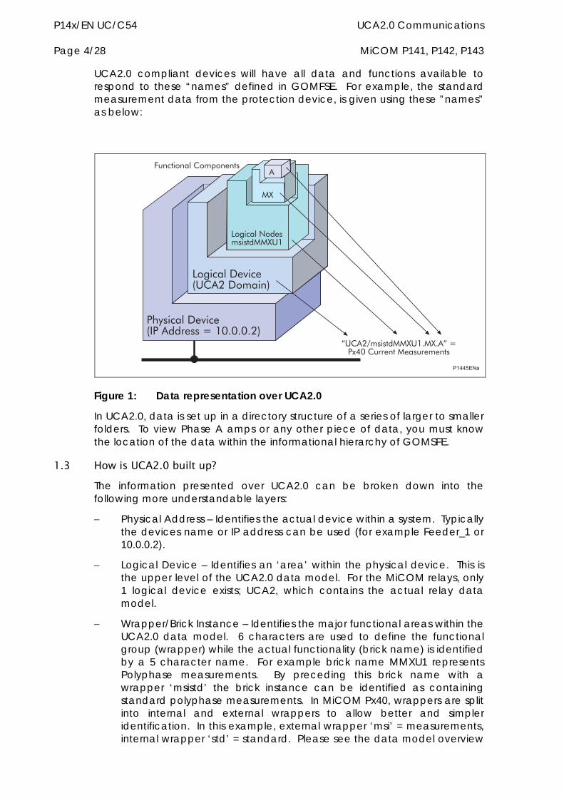
P14x/EN UC/C54 UCA2.0 Communications Page 4/28 MiCOM P141, P142, P143
UCA2.0 compliant devices will have all data and functions available to respond to these “names” defined in GOMFSE. For example, the standard measurement data from the protection device, is given using these ”names” as below:
��������� �����������������������
�������� ���������������
������ ��������!�""#��
"#
�
$����%����!�""#���"#��&��'(��)����!"���)�����!�
*)��!�������+����!�
��������
Figure 1: Data representation over UCA2.0
In UCA2.0, data is set up in a directory structure of a series of larger to smaller folders. To view Phase A amps or any other piece of data, you must know the location of the data within the informational hierarchy of GOMSFE.
1.3 How is UCA2.0 built up? The information presented over UCA2.0 can be broken down into the following more understandable layers:
Physical Address – Identifies the actual device within a system. Typically the devices name or IP address can be used (for example Feeder_1 or 10.0.0.2).
Logical Device – Identifies an ‘area’ within the physical device. This is the upper level of the UCA2.0 data model. For the MiCOM relays, only 1 logical device exists; UCA2, which contains the actual relay data model.
Wrapper/Brick Instance – Identifies the major functional areas within the UCA2.0 data model. 6 characters are used to define the functional group (wrapper) while the actual functionality (brick name) is identified by a 5 character name. For example brick name MMXU1 represents Polyphase measurements. By preceding this brick name with a wrapper ‘msistd’ the brick instance can be identified as containing standard polyphase measurements. In MiCOM Px40, wrappers are split into internal and external wrappers to allow better and simpler identification. In this example, external wrapper ‘msi’ = measurements, internal wrapper ‘std’ = standard. Please see the data model overview
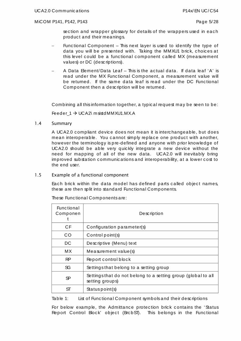
UCA2.0 Communications P14x/EN UC/C54 MiCOM P141, P142, P143 Page 5/28
section and wrapper glossary for details of the wrappers used in each product and their meanings.
Functional Component – This next layer is used to identify the type of data you will be presented with. Taking the MMXU1 brick, choices at this level could be a functional component called MX (measurement values) or DC (descriptions).
A Data Element/Data Leaf – This is the actual data. If data leaf ‘A’ is read under the MX Functional Component, a measurement value will be returned. If the same data leaf is read under the DC Functional Component then a description will be returned.
Combining all this information together, a typical request may be seen to be:
Feeder_1 UCA2\msistdMMXU1.MX.A
1.4 Summary A UCA2.0 compliant device does not mean it is interchangeable, but does mean interoperable. You cannot simply replace one product with another, however the terminology is pre-defined and anyone with prior knowledge of UCA2.0 should be able very quickly integrate a new device without the need for mapping of all of the new data. UCA2.0 will inevitably bring improved substation communications and interoperability, at a lower cost to the end user.
1.5 Example of a functional component Each brick within the data model has defined parts called object names, these are then split into standard Functional Components.
These Functional Components are:
Functional Componen
t Description
CF Configuration parameter(s)
CO Control point(s)
DC Descriptive (Menu) text
MX Measurement value(s)
RP Report control block
SG Settings that belong to a setting group
SP Settings that do not belong to a setting group (global to all setting groups)
ST Status point(s)
Table 1: List of Functional Component symbols and their descriptions
For below example, the Admittance protection brick contains the ‘Status Report Control Block’ object (BrcbST). This belongs in the Functional

P14x/EN UC/C54 UCA2.0 Communications Page 6/28 MiCOM P141, P142, P143
Component RP and contains different Class Items such as BufTim, DatSet etc. These class items are where the actual data is stored.
Object Name FC Class Item Description
BrcbST Status Report Control Block
RP BufTim Buffer Time
RP DatSet Data Set
Elements under all Functional Components except CF and RP have a description (DC [menu text]). Elements belonging to the SP, SG, CO and MX Functional Components also have configuration parameters (CF).
The configuration parameter (CF) Functional Component may contain the following components. Depending upon the brick and object it is associated with. Some may have only deadbands, some may have increments, max/min values and units.
Incr/Incri – Setting Increment*
Max/maxi – Maximum setting value*
Min/mini – Minimum setting value*
Db/dbf – Deadband value Integer, (f) indicates floating point deadband
Ondur/offdur – On and Off duration for controls/commands
U – Setting/Measurement units.
Note: * Components Incri/Maxi/Mini represents integer values instead of floating point.
UCA2.0 Communications P14x/EN UC/C54 MiCOM P141, P142, P143 Page 7/28
2. INTRODUCTION TO UCA2.0 GOOSE The implementation of UCA2.0 Generic Object Orientated Substation Events (GOOSE) sets the way for cheaper and faster inter-relay communications. UCA2.0 GOOSE is based upon the principle of reporting the state of a selection of binary (i.e. ON or OFF) signals to other devices. In the case of Px40 relays, these binary signals are derived from the Programmable Scheme Logic Digital Data Bus signals.
UCA2.0 GOOSE messages are event-driven. When a monitored point changes state, e.g. from logic 0 to logic 1, a new message is sent. The device will wait for a pre-calculated time and then re-send the message. The calculation of this delay time is defined by GOMFSE. It increases with each re-transmission until the maximum delay time is reached (defined by the GOOSE Max Cycle setting).
To ensure the fastest possible transfer of information, UCA2.0 GOOSE messages are sent as multicast packets over the network. An advantage to this method is the fact that all devices connected to the same network* will see the message.
Note: * Multicast messages cannot be routed across networks without specialised equipment.
The use of multicast messaging means that UCA2.0 GOOSE uses a publisher-subscriber system to transfer information around the network. When a device detects a change in one of it’s monitored status points it publishes (i.e. sends) a message. Any device that is interested in the information subscribes (i.e. listens) to the data it contains.
2.1 UCA2.0 GOOSE message structure The structure of information transmitted via UCA2.0 GOOSE is defined by the 'Protection Action' (PACT) common class template, defined by GOMFSE.
A UCA2.0 GOOSE message transmitted by a Px40 relay can carry up to 96 Digital Data Bus signals, where the monitored signals are characterised by a two-bit status value, or "bit-pair". The value transmitted in the bit-pair is customisable although GOMFSE recommends the following assignments:
Bit Pair Value Represents
00 A transitional or unknown state
01 A logical 0 or OFF state
10 A logical 1 or ON state
11 An invalid state
Table 2: UCA2.0 GOOSE message bit-pair assignment values
The PACT common class splits the contents of a UCA2.0 GOOSE message into two main parts; 32 DNA bit-pairs and 64 User Status bit-pairs.
The DNA bit-pairs are intended to carry GOMSFE defined protection scheme information, where supported by the device. MiCOM Px40 implementation provides full end-user flexibility, as it is possible to assign any Digital Data Bus signal to any of the 32 DNA bit-pairs. The User Status bit pairs are intended to
P14x/EN UC/C54 UCA2.0 Communications Page 8/28 MiCOM P141, P142, P143
carry all ‘user-defined’ state and control information. As with the DNA, it is possible to assign any Digital Data Bus signal to these bit-pairs.
To ensure full compatibility with third party UCA2.0 GOOSE enabled products, it is recommended that the DNA bit-pair assignments are as per the definition given in GOMFSE.
2.2 UCA2.0 GOOSE message configuration A new UCA2.0 GOOSE message is transmitted whenever a monitored signal changes state (e.g. from logic 0 to logic 1). The reception of these messages in the presence of noise must be considered. Subscribing devices are reliant on the message reception in order to track the state of the device. Following a change of state, the bit-pairs being transmitted must be acquired dependably.
To ensure reliable reception of a device’s state, a message retransmission strategy is used. This strategy works very well in the presence of burst noise. The probability of a single corrupted or missed message is greater than the probability of two successive corrupted or missed messages. This reduces rapidly as more messages are transmitted. It therefore seem sensible to rapidly transmit many UCA2.0 GOOSE messages in the hope that at least some will be received in the order of 10ms. However, rapidly transmitting many UCA2.0 GOOSE messages consumes available network bandwidth and increases the probability of collision delays. Network availability for other devices and protocols also decreases. Thus, the design of a UCA2.0 GOOSE scheme must allow sufficient network access time to all devices and other protocols, in order for the scheme to work reliably.
The reliability of a UCA2.0 GOOSE scheme relates to the maximum time that can elapse between message retransmissions, before the validity period expires. Each message has a validity period, if this is reached, the message is deemed to have expired. This is unacceptable, as you will no longer be sure of the device’s state. When a message expires in this way, the subscribing device will revert to a set of safe default values. In order to prevent a message from expiring, a new (or retransmitted) message must be received within the expiry period.
Reliable schemes use a low message rate, which leads to the opposing demands of scheme dependability, which requires a high message rate. Reliable schemes achieve good network utilisation, while the increased message rate of a dependable scheme increases the probability that the message is received in the order of 10 milliseconds. To make matters worse, these attributes are affected by many other parameters, some of which are:
number of transmitting devices on the network
responsiveness of the scheme to new events
probability of simultaneous event message transmission
probability of event avalanches
probability of message corruption on the network
ability of the network infrastructure to manage simultaneous broadcast/multicast messages
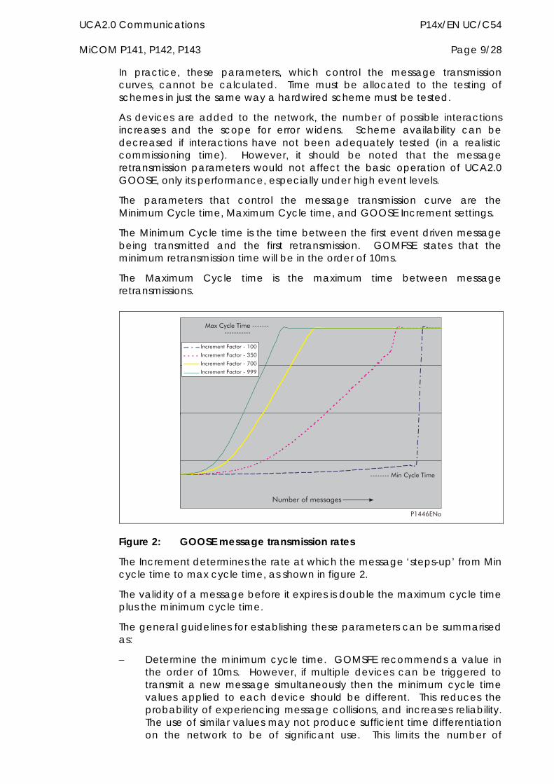
UCA2.0 Communications P14x/EN UC/C54 MiCOM P141, P142, P143 Page 9/28
In practice, these parameters, which control the message transmission curves, cannot be calculated. Time must be allocated to the testing of schemes in just the same way a hardwired scheme must be tested.
As devices are added to the network, the number of possible interactions increases and the scope for error widens. Scheme availability can be decreased if interactions have not been adequately tested (in a realistic commissioning time). However, it should be noted that the message retransmission parameters would not affect the basic operation of UCA2.0 GOOSE, only its performance, especially under high event levels.
The parameters that control the message transmission curve are the Minimum Cycle time, Maximum Cycle time, and GOOSE Increment settings.
The Minimum Cycle time is the time between the first event driven message being transmitted and the first retransmission. GOMFSE states that the minimum retransmission time will be in the order of 10ms.
The Maximum Cycle time is the maximum time between message retransmissions.
)�,���-��������
........"������/���
"�'����/���..................
��������!*��!��.���
��������!*��!��.01���������!*��!��.2����������!*��!��.333
��((45 �
Figure 2: GOOSE message transmission rates
The Increment determines the rate at which the message ‘steps-up’ from Min cycle time to max cycle time, as shown in figure 2.
The validity of a message before it expires is double the maximum cycle time plus the minimum cycle time.
The general guidelines for establishing these parameters can be summarised as:
Determine the minimum cycle time. GOMSFE recommends a value in the order of 10ms. However, if multiple devices can be triggered to transmit a new message simultaneously then the minimum cycle time values applied to each device should be different. This reduces the probability of experiencing message collisions, and increases reliability. The use of similar values may not produce sufficient time differentiation on the network to be of significant use. This limits the number of
P14x/EN UC/C54 UCA2.0 Communications Page 10/28 MiCOM P141, P142, P143
practical values that may be used whilst remaining close to the 10ms objective set by GOMSFE.
Determine the maximum duration that a sending device’s messages are valid. Given each device’s minimum cycle time, the maximum cycle time will be half the message valid time, minus the minimum cycle time. A typical message valid time value for an inter-tripping scheme is 2s, which gives a typical maximum cycle time of 1s. Blocking schemes are typically more tolerant and message validity times can be extended.
The increment value should be chosen such that it is as small as possible but different for each device sharing a common (or similar) minimum cycle time value. This will provide a degree of time differentiation as retransmissions occur. Small increment values cause the retransmission delay to slowly increase to the maximum value (increasing dependability), whereas a large increment value will cause it to rapidly increase (increasing reliability). See figure 2.
Analysing which devices in the scheme are likely to respond simultaneously may require the subdivision of a scheme into smaller clusters of devices. This may also help in determining the retransmission parameters. Splitting large networks into smaller segments using routers etc. will help limit the effects of GOOSE message avalanches, but will require specialist equipment to pass (route) GOOSE messages between isolated segments.
UCA2.0 Communications P14x/EN UC/C54 MiCOM P141, P142, P143 Page 11/28
3. UCA2.0 IN MiCOM PX40 UCA2.0 is implemented in MiCOM Px40 relays by use of a separate Ethernet Card. This card manages the majority of the UCA2.0 implementation and data transfer to avoid any impact on the performance of the protection.
3.1 Capability The UCA2.0 interface provides the following capabilities:
1. Read and Write access to relay settings and controls.
Setting cells associated with Control & Support functions (settings that do not belong to a protection group) are available in the Set Point (SP) Functional Component of a UCA2.0 brick.
Setting cells associated with Protection & Control functions (settings that belong to a protection group) are available in the Setting Group (SG) Functional Component of a UCA2.0 brick.
2. Read access to measurements.
All measurands are presented under the Measurement (MX) Functional Component of any supporting UCA2.0 brick.
3. Generation of reports on changes of measurements.
Measurement reports can be generated when user-defined criteria have been met. This will usually be in the form of a setting such as percentage change of a measurement (deadband). Reports are available for configuration under the Reporting (RP) Functional Component of a UCA2.0 brick.
4. Generation of reports when an event record is created.
Status reports can be generated by Protection events when user-defined reporting criteria have been met. This will usually be as a result of a protection element, such as Phase Overcurrent, starting or tripping. Reports are available for configuration under the Reporting (RP) Functional Component of a UCA2.0 brick.
5. Support for time synchronisation over an Ethernet link.
Time synchronisation is supported using SMP (Station Management Protocol); this protocol is used to synchronise the internal real time clock of the relays. For further information on this protocol, please visit www.sisconet.com
6. GOOSE Peer-to-Peer Communication
GOOSE communications are included as part of the UCA2.0 implementation. Please see sections 2 and 4 for more details.
7. Disturbance Record Extraction
Extraction of disturbance records is supported by the MiCOM Px40 relays. The record is extracted as an ASCII format COMTRADE file.
P14x/EN UC/C54 UCA2.0 Communications Page 12/28 MiCOM P141, P142, P143
3.2 Network connectivity Note: This section presumes a prior knowledge of IP addressing
and related topics. Further details on this topic may be found on the Internet (search for IP Configuration) and in numerous relevant books.
When configuring the relay for operation on a network, a unique IP address must be set on the relay. If the assigned IP address is duplicated elsewhere on the same network, the remote communications will operate in an indeterminate way. However, the relay will check for a conflict on every IP configuration change and at power up. An alarm will be raised if an IP conflict is detected. Similarly, a relay set with an invalid IP configuration (or factory default) will also cause an alarm to be displayed (Bad TCP/IP Cfg.).
The relay can be configured to accept data from networks other than the local network by using the ‘Router Address’ and ‘Target Network’ settings. The Router Address is the IP address of the router that is providing the sub-network interconnectivity. The Target Network is the base IP address of the remote network. Setting the Target Network to 000.000.000.000 will force the relay to use the specified router as the 'default gateway' for all data other than that produced on the local network.
3.3 Access to measurements All the relay measurements are presented over UCA2.0 using the ‘Measurement’ functional component (MX) or parts of it. Reported measurement values are refreshed by the relay once per second, inline with the relay User Interface. All measurements supported are listed in the product data model.
3.4 Settings 3.4.1 Remote setting management
The UCA2.0 interface provides access to all setting groups within the relay. The visible setting group can be changed by the control ‘EditSG’ within the ‘GLOBE’ brick (write to this control).
The active setting group is changed by the control ‘ActSG’ within the ‘GLOBE’ brick, with the value of the corresponding setting group (Group2 = 2 etc) to make active. If the specified setting group is disabled, an error response will be generated. Changing the active setting group does not affect the setting group visible for editing over the UCA2.0 interface.
Setting groups can be enabled or disabled, however it is possible to view any setting group regardless if disabled. It is not possible to set a disabled setting group as the active group, equally, it is not possible to disable the active setting group.
To confirm changes made within a setting group, the control ‘SaveSG’ in the GLOBE brick must be used. Writing a value (1, 2, 3 or 4) to ‘SaveSG’ will save any changes made to the corresponding setting group number.
3.4.2 Accessing settings and controls
The UCA2.0 interface is able to read and write to both control and support settings (through the ‘Set Point’, SP functional component). The protection settings use the ‘Group Set Point’, SG functional component.
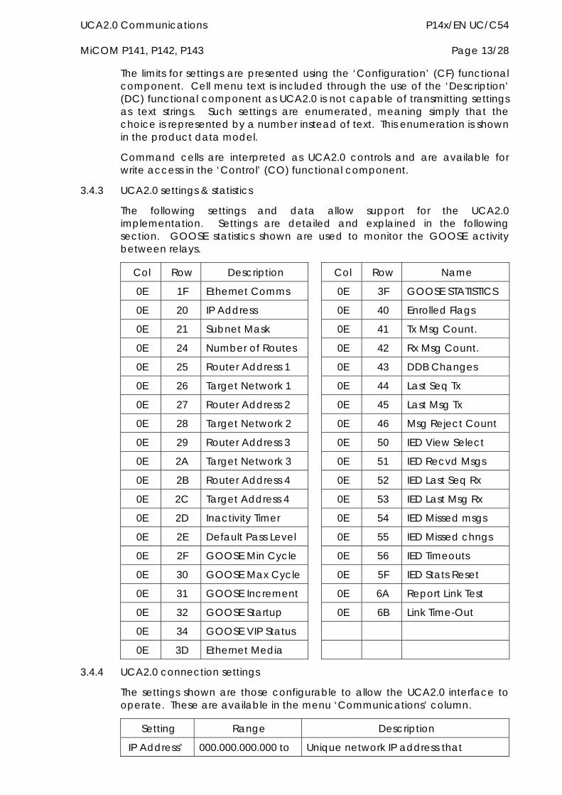
UCA2.0 Communications P14x/EN UC/C54 MiCOM P141, P142, P143 Page 13/28
The limits for settings are presented using the ‘Configuration’ (CF) functional component. Cell menu text is included through the use of the ‘Description’ (DC) functional component as UCA2.0 is not capable of transmitting settings as text strings. Such settings are enumerated, meaning simply that the choice is represented by a number instead of text. This enumeration is shown in the product data model.
Command cells are interpreted as UCA2.0 controls and are available for write access in the ‘Control’ (CO) functional component.
3.4.3 UCA2.0 settings & statistics
The following settings and data allow support for the UCA2.0 implementation. Settings are detailed and explained in the following section. GOOSE statistics shown are used to monitor the GOOSE activity between relays.
Col Row Description Col Row Name
0E 1F Ethernet Comms 0E 3F GOOSE STATISTICS
0E 20 IP Address 0E 40 Enrolled Flags
0E 21 Subnet Mask 0E 41 Tx Msg Count.
0E 24 Number of Routes 0E 42 Rx Msg Count.
0E 25 Router Address 1 0E 43 DDB Changes
0E 26 Target Network 1 0E 44 Last Seq Tx
0E 27 Router Address 2 0E 45 Last Msg Tx
0E 28 Target Network 2 0E 46 Msg Reject Count
0E 29 Router Address 3 0E 50 IED View Select
0E 2A Target Network 3 0E 51 IED Recvd Msgs
0E 2B Router Address 4 0E 52 IED Last Seq Rx
0E 2C Target Address 4 0E 53 IED Last Msg Rx
0E 2D Inactivity Timer 0E 54 IED Missed msgs
0E 2E Default Pass Level 0E 55 IED Missed chngs
0E 2F GOOSE Min Cycle 0E 56 IED Timeouts
0E 30 GOOSE Max Cycle 0E 5F IED Stats Reset
0E 31 GOOSE Increment 0E 6A Report Link Test
0E 32 GOOSE Startup 0E 6B Link Time-Out
0E 34 GOOSE VIP Status
0E 3D Ethernet Media
3.4.4 UCA2.0 connection settings
The settings shown are those configurable to allow the UCA2.0 interface to operate. These are available in the menu ‘Communications’ column.
Setting Range Description
IP Address* 000.000.000.000 to Unique network IP address that
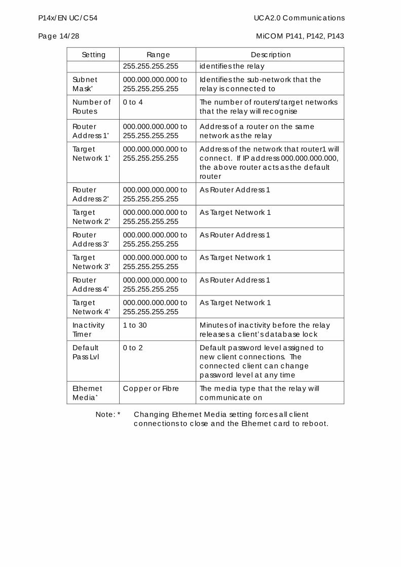
P14x/EN UC/C54 UCA2.0 Communications Page 14/28 MiCOM P141, P142, P143
Setting Range Description 255.255.255.255 identifies the relay
Subnet Mask*
000.000.000.000 to 255.255.255.255
Identifies the sub-network that the relay is connected to
Number of Routes
0 to 4 The number of routers/target networks that the relay will recognise
Router Address 1*
000.000.000.000 to 255.255.255.255
Address of a router on the same network as the relay
Target Network 1*
000.000.000.000 to 255.255.255.255
Address of the network that router1 will connect. If IP address 000.000.000.000, the above router acts as the default router
Router Address 2*
000.000.000.000 to 255.255.255.255
As Router Address 1
Target Network 2*
000.000.000.000 to 255.255.255.255
As Target Network 1
Router Address 3*
000.000.000.000 to 255.255.255.255
As Router Address 1
Target Network 3*
000.000.000.000 to 255.255.255.255
As Target Network 1
Router Address 4*
000.000.000.000 to 255.255.255.255
As Router Address 1
Target Network 4*
000.000.000.000 to 255.255.255.255
As Target Network 1
Inactivity Timer
1 to 30 Minutes of inactivity before the relay releases a client’s database lock
Default Pass Lvl
0 to 2 Default password level assigned to new client connections. The connected client can change password level at any time
Ethernet Media*
Copper or Fibre The media type that the relay will communicate on
Note: * Changing Ethernet Media setting forces all client connections to close and the Ethernet card to reboot.
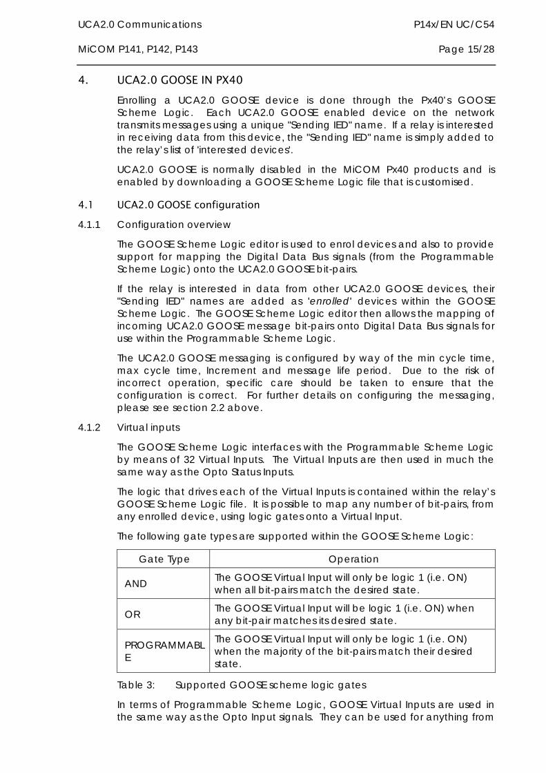
UCA2.0 Communications P14x/EN UC/C54 MiCOM P141, P142, P143 Page 15/28
4. UCA2.0 GOOSE IN PX40 Enrolling a UCA2.0 GOOSE device is done through the Px40’s GOOSE Scheme Logic. Each UCA2.0 GOOSE enabled device on the network transmits messages using a unique "Sending IED" name. If a relay is interested in receiving data from this device, the "Sending IED" name is simply added to the relay’s list of 'interested devices'.
UCA2.0 GOOSE is normally disabled in the MiCOM Px40 products and is enabled by downloading a GOOSE Scheme Logic file that is customised.
4.1 UCA2.0 GOOSE configuration 4.1.1 Configuration overview
The GOOSE Scheme Logic editor is used to enrol devices and also to provide support for mapping the Digital Data Bus signals (from the Programmable Scheme Logic) onto the UCA2.0 GOOSE bit-pairs.
If the relay is interested in data from other UCA2.0 GOOSE devices, their "Sending IED" names are added as 'enrolled' devices within the GOOSE Scheme Logic. The GOOSE Scheme Logic editor then allows the mapping of incoming UCA2.0 GOOSE message bit-pairs onto Digital Data Bus signals for use within the Programmable Scheme Logic.
The UCA2.0 GOOSE messaging is configured by way of the min cycle time, max cycle time, Increment and message life period. Due to the risk of incorrect operation, specific care should be taken to ensure that the configuration is correct. For further details on configuring the messaging, please see section 2.2 above.
4.1.2 Virtual inputs
The GOOSE Scheme Logic interfaces with the Programmable Scheme Logic by means of 32 Virtual Inputs. The Virtual Inputs are then used in much the same way as the Opto Status Inputs.
The logic that drives each of the Virtual Inputs is contained within the relay’s GOOSE Scheme Logic file. It is possible to map any number of bit-pairs, from any enrolled device, using logic gates onto a Virtual Input.
The following gate types are supported within the GOOSE Scheme Logic:
Gate Type Operation
AND The GOOSE Virtual Input will only be logic 1 (i.e. ON) when all bit-pairs match the desired state.
OR The GOOSE Virtual Input will be logic 1 (i.e. ON) when any bit-pair matches its desired state.
PROGRAMMABLE
The GOOSE Virtual Input will only be logic 1 (i.e. ON) when the majority of the bit-pairs match their desired state.
Table 3: Supported GOOSE scheme logic gates
In terms of Programmable Scheme Logic, GOOSE Virtual Inputs are used in the same way as the Opto Input signals. They can be used for anything from
P14x/EN UC/C54 UCA2.0 Communications Page 16/28 MiCOM P141, P142, P143
inputs to complex logic implementations or directly mapped onto a programmable LED or relay contact output.
4.1.3 Virtual outputs
The Programmable Scheme Logic provides 32 Virtual Output signals that can be connected to incoming signals or outputs of logic gates. The Virtual Outputs are used in much the same way as contact output signals and their use can simplify otherwise complex logic assignments between Programmable Scheme Logic and GOOSE Scheme Logic bit-pairs. Any Digital Data Bus signal can be assigned to GOOSE Scheme Logic bit-pairs, not just the Virtual Outputs.
4.2 UCA2.0 GOOSE processing & pre-sets Under certain circumstances, it may be necessary to force a bit-pair to be a pre-set value. This could be used for testing or when certain operating conditions exist.
4.2.1 Pre-processing
Prior to a UCA2.0 GOOSE message being transmitted, the DNA and User Status bit-pairs can be forced to pre-set values as required. This is accomplished on a 'per bit-pair' basis either off-line using the GOOSE Scheme Logic editor or on-line using the following components of the GLOBE UCA2 data model brick:
SelOutDNA Output selection for DNA bit pairs (pass through or preset)
SelOutUserSt Output selection for UserSt bit pairs (pass through or preset)
PresetDNA * Preset values for DNA bit pairs
PresetUserSt * Preset values for UserSt bit pairs
Note: * Not used when SelOutDNA and SelOutUserSt are pass through.
4.2.2 Post-processing
Immediately after receiving a UCA2.0 GOOSE message, the DNA and User Status bit-pairs are processed and can be set to one of three possible values; Pass through, default or forced. The selection is controlled off-line using the GOOSE Scheme editor or on-line using the following components of the GLOBE UCA2 data model brick:
SelinDNA Input selection for DNA bit pairs (pass though, default or forced)
SelinUserSt Input selection for UserSt bit pairs (pass though, default or forced) DefDNA * Default values for DNA bit pairs
UCA2.0 Communications P14x/EN UC/C54 MiCOM P141, P142, P143 Page 17/28
ForDNA * Forced values for DNA bit pairs DefUserSt * Default values for UserSt bit pairs ForUserSt * Forced values for UserSt bit pairs
Note: * Not used when SelinDNA and SelinUserSt are pass through.
The input selection is accomplished on a 'per bit-pair' basis where; 'Pass through' uses the data received in the message. 'Default' uses a set of scheme safe values suitable if a device is unable to transmit messages. ' Forced' uses a set of overriding values for exercising required scheme functionality.
4.3 UCA2.0 GOOSE start-up modes The MiCOM implementation supports two UCA2.0 GOOSE start-up modes. Promiscuous start-up is compatible with all UCA2.0 GOOSE devices. Broadcast start-up is specific to MiCOM devices and may not be compatible with other UCA2.0 GOOSE devices.
Within a single scheme, the start-up mode across all devices must be consistent to guarantee scheme operation.
4.3.1 Promiscuous start-up
When a MiCOM relay switches on, the UCA2.0 GOOSE processes will be initiated. At this point, the relay knows its own configuration and from which other devices UCA2.0 GOOSE messages will be received.
The Ethernet hardware will be set into a promiscuous mode of operation, whereby it will receive all Ethernet messages regardless of their target address. When in promiscuous mode, unwanted messages will be filtered by examining the destination MAC address. It will accept messages under the following conditions:
Those addressed to the relay
All multicast messages
All broadcast messages
All received UCA2.0 GOOSE messages will be checked against the scheme configuration. If the relay has subscribed to the received message, the transmitting device’s MAC address is recorded (enrolled).
When all subscribed devices have been enrolled, the relay will revert from promiscuous mode and enter normal mode to receive messages from the specified multicast MAC addresses of the enrolled devices.
When starting, the relay will transmit a message as soon as the DNA and User status bit-pairs are in a valid state. This allows subscribing devices to enrol this relay’s MAC address.
If a received message is timed out, a network problem is deemed to exist and the Ethernet hardware will be placed in promiscuous mode. All messages will be monitored until the failed device(s) re-appear.
P14x/EN UC/C54 UCA2.0 Communications Page 18/28 MiCOM P141, P142, P143
The promiscuous method places extra load on the relay when one or more subscribed devices are not operational and transmitting messages. This may be a problem in systems where there is much network traffic as there is chance that schemes may start experiencing problems.
4.3.2 Broadcast start-up
When a MiCOM relay switches on, the UCA2.0 GOOSE process is initiated. At this point the relay knows its own configuration and from which other devices messages will be received.
The starting relay will broadcast (rather than multicast) a set of messages as soon as the DNA and User status bit-pairs are in a valid state. Other MiCOM devices on the network will recognise this broadcast message. If subscribed to the starting device, its MAC address is recorded and a message is transmitted back to the device (addressed not broadcast or multicast). This allows the starting device to configure its own GOOSE management. If the starting relay has subscribed to the received message, the transmitting device’s MAC address is (enrolled).
This broadcast mechanism allows the starting device to construct a list of transmitting devices (from the returned messages), and allows other devices on the network to enrol the starting device. This approach achieves a known scheme state in a faster time when compared to the promiscuous start-up.
4.4 Ethernet hardware The optional Ethernet card (ZN0012) has 2 variants which supports the UCA2.0 implementation, one card with RJ45 and ST (10Mb card), the other with RJ45 and SC (100Mb card). This allows the following connection media:
10BASE-T – 10Mb Copper Connection (RJ45 type)
10BASE-FL – 10Mb Fibre Optic Connection (ST type)
100BASE-TX – 100Mb Copper Connection (RJ45 type)
100BASE-FX – 100Mb Fibre Optic Connection (SC type)
This card is fitted into Slot A of the relay, which is the optional communications slot.
When using UCA2.0 communications through the Ethernet Card, the rear EIA(RS)485 and front EIA(RS)232 ports are also available for simultaneous use, using the Courier Protocol.
Each Ethernet card has a unique ‘Mac address’ used for Ethernet communications, this is also printed on the rear of the card, alongside the Ethernet sockets.
4.4.1 Ethernet disconnection
UCA2.0 ‘Associations’ are unique and made to the relay between the client (master) and server (UCA2.0 device). In the event that the Ethernet is disconnected, such associations cannot be remade. Since there is no more interaction via the old association, the relay cancels it making it available for other clients.

UCA2.0 Communications P14x/EN UC/C54 MiCOM P141, P142, P143 Page 19/28
4.4.2 Loss of power
The relay allows the re-establishment of associations without a negative impact on the relays operation after having its power removed. As the relay acts as a server in this process, the client must request the association. Uncommitted setting are cancelled when power is lost, and reports requested by connected clients are reset and must be re-enabled by the client when it next creates the new association to the relay.
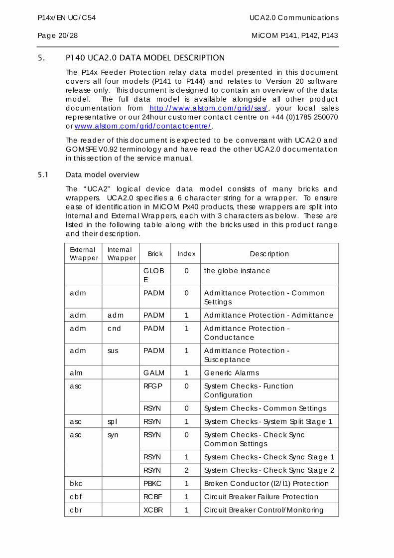
P14x/EN UC/C54 UCA2.0 Communications Page 20/28 MiCOM P141, P142, P143
5. P140 UCA2.0 DATA MODEL DESCRIPTION The P14x Feeder Protection relay data model presented in this document covers all four models (P141 to P144) and relates to Version 20 software release only. This document is designed to contain an overview of the data model. The full data model is available alongside all other product documentation from http://www.alstom.com/grid/sas/, your local sales representative or our 24hour customer contact centre on +44 (0)1785 250070 or www.alstom.com/grid/contactcentre/.
The reader of this document is expected to be conversant with UCA2.0 and GOMSFE V0.92 terminology and have read the other UCA2.0 documentation in this section of the service manual.
5.1 Data model overview The “UCA2” logical device data model consists of many bricks and wrappers. UCA2.0 specifies a 6 character string for a wrapper. To ensure ease of identification in MiCOM Px40 products, these wrappers are split into Internal and External Wrappers, each with 3 characters as below. These are listed in the following table along with the bricks used in this product range and their description.
External Wrapper
Internal Wrapper Brick Index Description
GLOBE
0 the globe instance
adm PADM 0 Admittance Protection - Common Settings
adm adm PADM 1 Admittance Protection - Admittance
adm cnd PADM 1 Admittance Protection - Conductance
adm sus PADM 1 Admittance Protection - Susceptance
alm GALM 1 Generic Alarms
RFGP 0 System Checks - Function Configuration
asc
RSYN 0 System Checks - Common Settings
asc spl RSYN 1 System Checks - System Split Stage 1
RSYN 0 System Checks - Check Sync Common Settings
RSYN 1 System Checks - Check Sync Stage 1
asc syn
RSYN 2 System Checks - Check Sync Stage 2
bkc PBKC 1 Broken Conductor (I2/I1) Protection
cbf RCBF 1 Circuit Breaker Failure Protection
cbr XCBR 1 Circuit Breaker Control/Monitoring
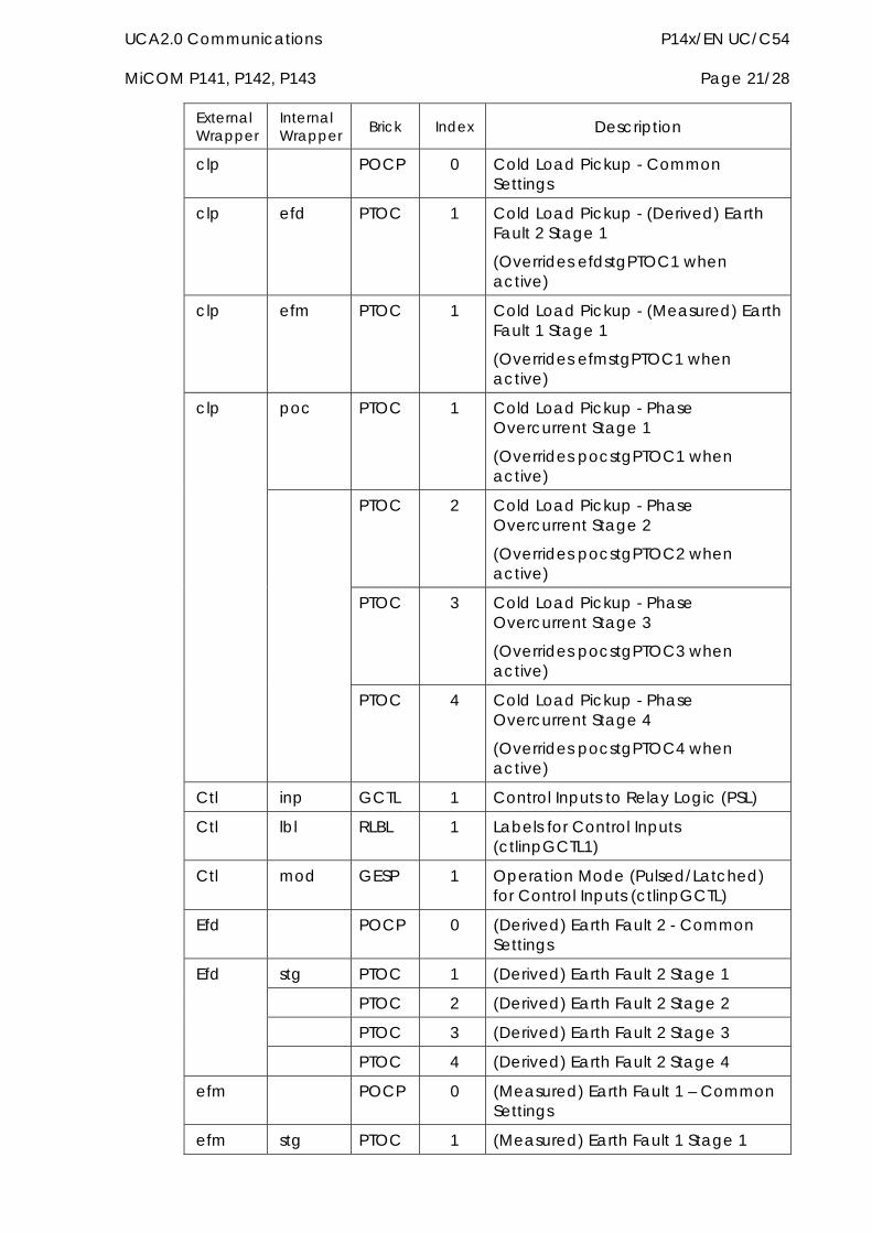
UCA2.0 Communications P14x/EN UC/C54 MiCOM P141, P142, P143 Page 21/28
External Wrapper
Internal Wrapper Brick Index Description
clp POCP 0 Cold Load Pickup - Common Settings
clp efd PTOC 1 Cold Load Pickup - (Derived) Earth Fault 2 Stage 1
(Overrides efdstgPTOC1 when active)
clp efm PTOC 1 Cold Load Pickup - (Measured) Earth Fault 1 Stage 1
(Overrides efmstgPTOC1 when active)
poc PTOC 1 Cold Load Pickup - Phase Overcurrent Stage 1
(Overrides pocstgPTOC1 when active)
PTOC 2 Cold Load Pickup - Phase Overcurrent Stage 2
(Overrides pocstgPTOC2 when active)
PTOC 3 Cold Load Pickup - Phase Overcurrent Stage 3
(Overrides pocstgPTOC3 when active)
clp
PTOC 4 Cold Load Pickup - Phase Overcurrent Stage 4
(Overrides pocstgPTOC4 when active)
Ctl inp GCTL 1 Control Inputs to Relay Logic (PSL)
Ctl lbl RLBL 1 Labels for Control Inputs (ctlinpGCTL1)
Ctl mod GESP 1 Operation Mode (Pulsed/Latched) for Control Inputs (ctlinpGCTL)
Efd POCP 0 (Derived) Earth Fault 2 - Common Settings
stg PTOC 1 (Derived) Earth Fault 2 Stage 1
PTOC 2 (Derived) Earth Fault 2 Stage 2
PTOC 3 (Derived) Earth Fault 2 Stage 3
Efd
PTOC 4 (Derived) Earth Fault 2 Stage 4
efm POCP 0 (Measured) Earth Fault 1 – Common Settings
efm stg PTOC 1 (Measured) Earth Fault 1 Stage 1
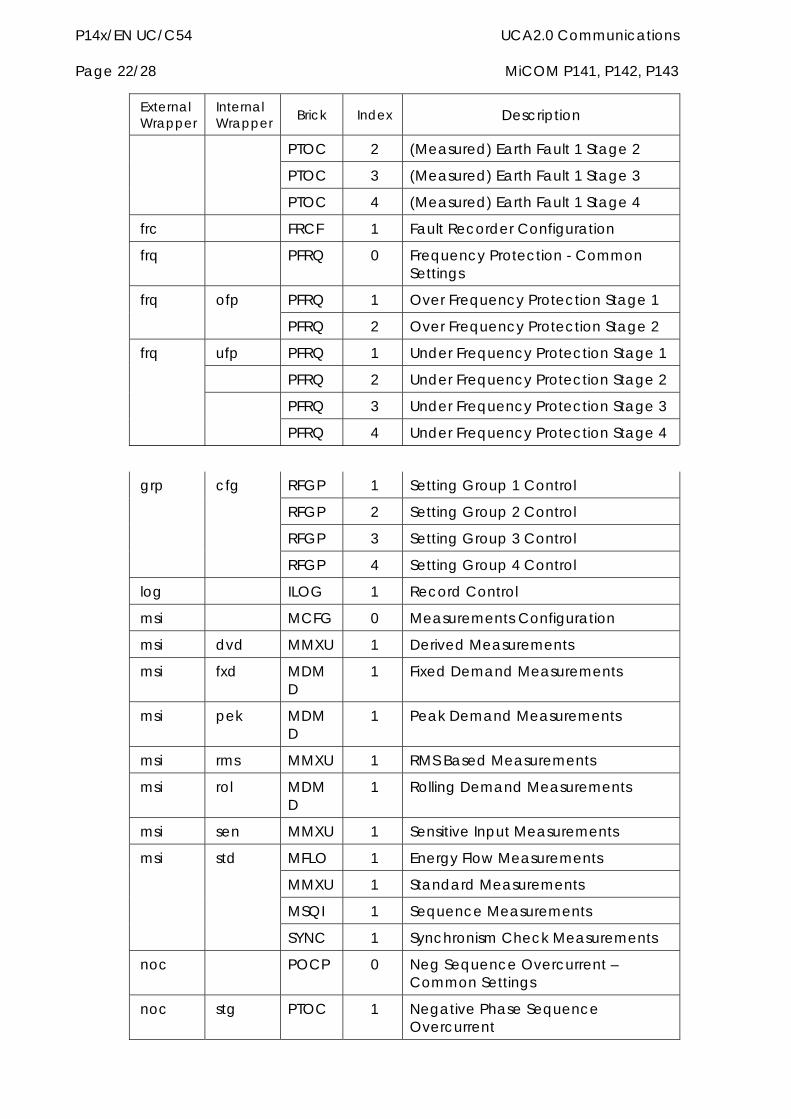
P14x/EN UC/C54 UCA2.0 Communications Page 22/28 MiCOM P141, P142, P143
External Wrapper
Internal Wrapper Brick Index Description
PTOC 2 (Measured) Earth Fault 1 Stage 2
PTOC 3 (Measured) Earth Fault 1 Stage 3
PTOC 4 (Measured) Earth Fault 1 Stage 4
frc FRCF 1 Fault Recorder Configuration
frq PFRQ 0 Frequency Protection - Common Settings
PFRQ 1 Over Frequency Protection Stage 1 frq ofp
PFRQ 2 Over Frequency Protection Stage 2
ufp PFRQ 1 Under Frequency Protection Stage 1
PFRQ 2 Under Frequency Protection Stage 2
PFRQ 3 Under Frequency Protection Stage 3
frq
PFRQ 4 Under Frequency Protection Stage 4
RFGP 1 Setting Group 1 Control
RFGP 2 Setting Group 2 Control
RFGP 3 Setting Group 3 Control
grp cfg
RFGP 4 Setting Group 4 Control
log ILOG 1 Record Control
msi MCFG 0 Measurements Configuration
msi dvd MMXU 1 Derived Measurements
msi fxd MDMD
1 Fixed Demand Measurements
msi pek MDMD
1 Peak Demand Measurements
msi rms MMXU 1 RMS Based Measurements
msi rol MDMD
1 Rolling Demand Measurements
msi sen MMXU 1 Sensitive Input Measurements
MFLO 1 Energy Flow Measurements
MMXU 1 Standard Measurements
MSQI 1 Sequence Measurements
msi std
SYNC 1 Synchronism Check Measurements
noc POCP 0 Neg Sequence Overcurrent – Common Settings
noc stg PTOC 1 Negative Phase Sequence Overcurrent
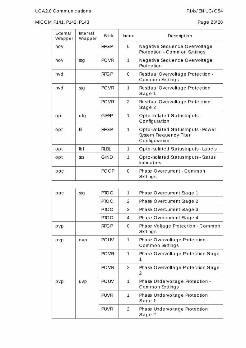
UCA2.0 Communications P14x/EN UC/C54 MiCOM P141, P142, P143 Page 23/28
External Wrapper
Internal Wrapper Brick Index Description
nov RFGP 0 Negative Sequence Overvoltage Protection - Common Settings
nov stg POVR 1 Negative Sequence Overvoltage Protection
nvd RFGP 0 Residual Overvoltage Protection - Common Settings
POVR 1 Residual Overvoltage Protection Stage 1
nvd stg
POVR 2 Residual Overvoltage Protection Stage 2
opt cfg GESP 1 Opto-Isolated Status Inputs - Configuration
opt fil RFGP 1 Opto-Isolated Status Inputs - Power System Frequency Filter Configuration
opt lbl RLBL 1 Opto-Isolated Status Inputs - Labels
opt sts GIND 1 Opto-Isolated Status Inputs - Status Indicators
poc POCP 0 Phase Overcurrent - Common Settings
PTOC 1 Phase Overcurrent Stage 1
PTOC 2 Phase Overcurrent Stage 2
PTOC 3 Phase Overcurrent Stage 3
poc stg
PTOC 4 Phase Overcurrent Stage 4
pvp RFGP 0 Phase Voltage Protection - Common Settings
POUV 1 Phase Overvoltage Protection - Common Settings
POVR 1 Phase Overvoltage Protection Stage 1
pvp ovp
POVR 2 Phase Overvoltage Protection Stage 2
POUV 1 Phase Undervoltage Protection - Common Settings
PUVR 1 Phase Undervoltage Protection Stage 1
pvp uvp
PUVR 2 Phase Undervoltage Protection Stage 2
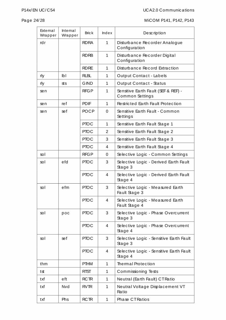
P14x/EN UC/C54 UCA2.0 Communications Page 24/28 MiCOM P141, P142, P143
External Wrapper
Internal Wrapper Brick Index Description
RDRA 1 Disturbance Recorder Analogue Configuration
RDRB 1 Disturbance Recorder Digital Configuration
rdr
RDRE 1 Disturbance Record Extraction
rly lbl RLBL 1 Output Contact - Labels
rly sts GIND 1 Output Contact - Status
sen RFGP 1 Sensitive Earth Fault (SEF & REF) - Common Settings
sen ref PDIF 1 Restricted Earth Fault Protection
POCP 0 Sensitive Earth Fault - Common Settings
PTOC 1 Sensitive Earth Fault Stage 1
PTOC 2 Sensitive Earth Fault Stage 2
PTOC 3 Sensitive Earth Fault Stage 3
sen sef
PTOC 4 Sensitive Earth Fault Stage 4
sol RFGP 0 Selective Logic - Common Settings
PTOC 3 Selective Logic - Derived Earth Fault Stage 3
sol efd
PTOC 4 Selective Logic - Derived Earth Fault Stage 4
PTOC 3 Selective Logic - Measured Earth Fault Stage 3
sol efm
PTOC 4 Selective Logic - Measured Earth Fault Stage 4
PTOC 3 Selective Logic - Phase Overcurrent Stage 3
sol poc
PTOC 4 Selective Logic - Phase Overcurrent Stage 4
PTOC 3 Selective Logic - Sensitive Earth Fault Stage 3
sol sef
PTOC 4 Selective Logic - Sensitive Earth Fault Stage 4
thm PTHM 1 Thermal Protection
tst RTST 1 Commissioning Tests
txf eft RCTR 1 Neutral (Earth Fault) CT Ratio
txf Nvd RVTR 1 Neutral Voltage Displacement VT Ratio
txf Phs RCTR 1 Phase CT Ratios
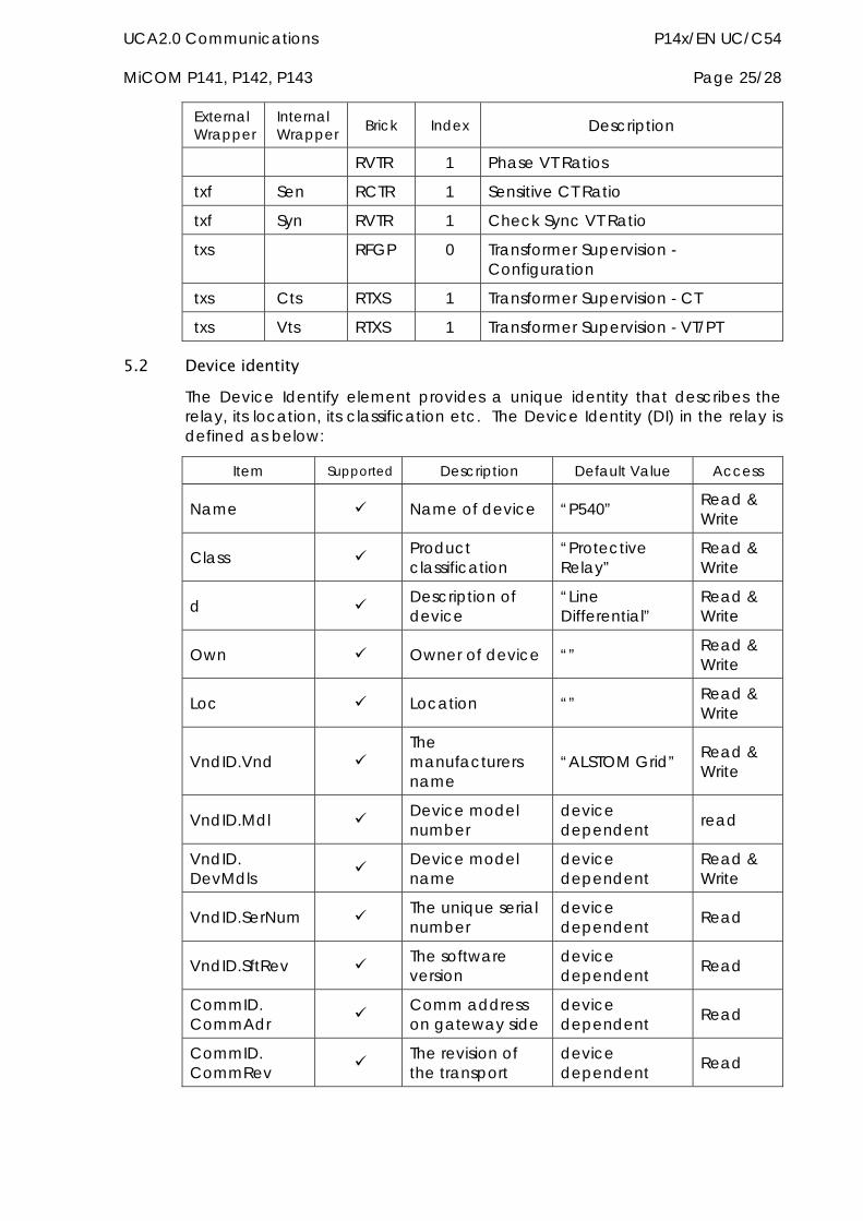
UCA2.0 Communications P14x/EN UC/C54 MiCOM P141, P142, P143 Page 25/28
External Wrapper
Internal Wrapper Brick Index Description
RVTR 1 Phase VT Ratios
txf Sen RCTR 1 Sensitive CT Ratio
txf Syn RVTR 1 Check Sync VT Ratio
txs RFGP 0 Transformer Supervision - Configuration
txs Cts RTXS 1 Transformer Supervision - CT
txs Vts RTXS 1 Transformer Supervision - VT/PT
5.2 Device identity The Device Identify element provides a unique identity that describes the relay, its location, its classification etc. The Device Identity (DI) in the relay is defined as below:
Item Supported Description Default Value Access
Name Name of device “P540” Read & Write
Class Product classification
“Protective Relay”
Read & Write
d Description of device
“Line Differential”
Read & Write
Own Owner of device “” Read & Write
Loc Location “” Read & Write
VndID.Vnd The manufacturers name
“ALSTOM Grid” Read & Write
VndID.Mdl Device model number
device dependent read
VndID. DevMdls Device model
name device dependent
Read & Write
VndID.SerNum The unique serial number
device dependent Read
VndID.SftRev The software version
device dependent Read
CommID. CommAdr Comm address
on gateway side device dependent Read
CommID. CommRev The revision of
the transport device dependent Read
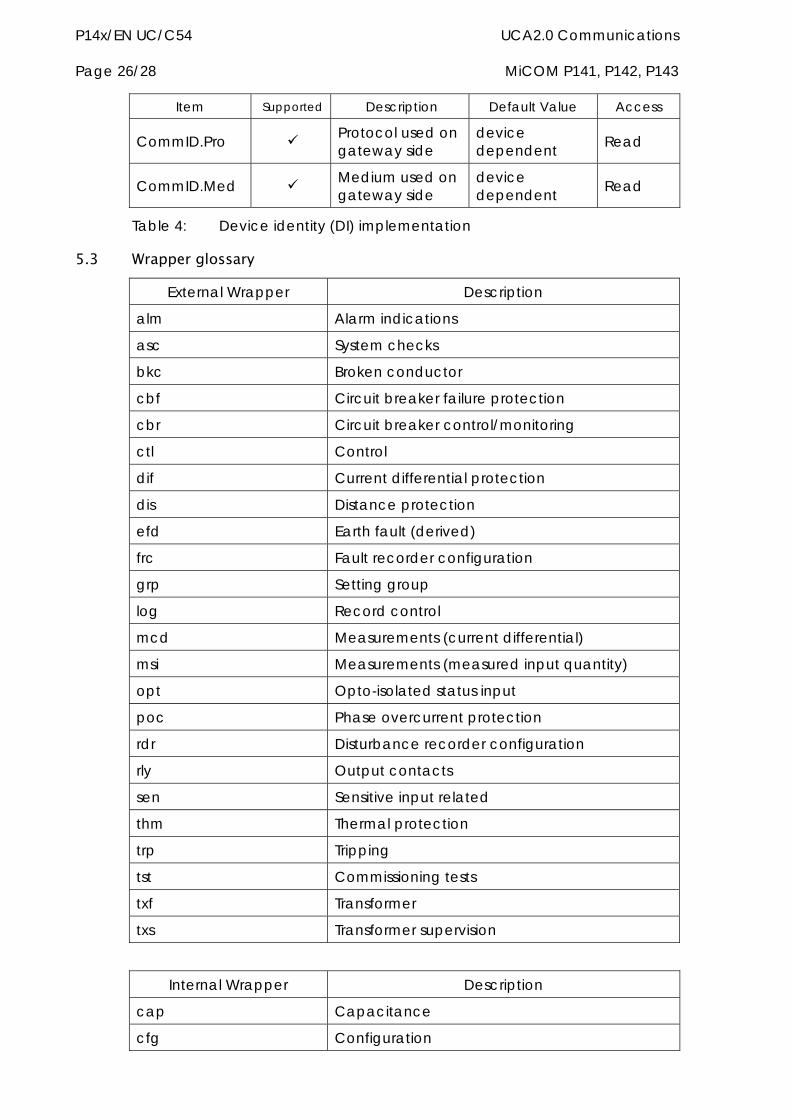
P14x/EN UC/C54 UCA2.0 Communications Page 26/28 MiCOM P141, P142, P143
Item Supported Description Default Value Access
CommID.Pro Protocol used on gateway side
device dependent Read
CommID.Med Medium used on gateway side
device dependent Read
Table 4: Device identity (DI) implementation
5.3 Wrapper glossary
External Wrapper Description
alm Alarm indications
asc System checks
bkc Broken conductor
cbf Circuit breaker failure protection
cbr Circuit breaker control/monitoring
ctl Control
dif Current differential protection
dis Distance protection
efd Earth fault (derived)
frc Fault recorder configuration
grp Setting group
log Record control
mcd Measurements (current differential)
msi Measurements (measured input quantity)
opt Opto-isolated status input
poc Phase overcurrent protection
rdr Disturbance recorder configuration
rly Output contacts
sen Sensitive input related
thm Thermal protection
trp Tripping
tst Commissioning tests
txf Transformer
txs Transformer supervision
Internal Wrapper Description
cap Capacitance
cfg Configuration
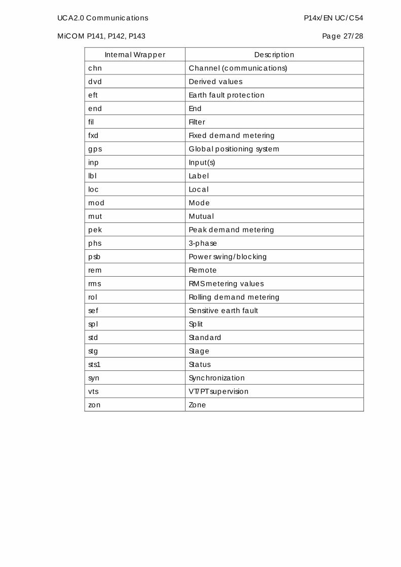
UCA2.0 Communications P14x/EN UC/C54 MiCOM P141, P142, P143 Page 27/28
Internal Wrapper Description
chn Channel (communications)
dvd Derived values
eft Earth fault protection
end End
fil Filter
fxd Fixed demand metering
gps Global positioning system
inp Input(s)
lbl Label
loc Local
mod Mode
mut Mutual
pek Peak demand metering
phs 3-phase
psb Power swing/blocking
rem Remote
rms RMS metering values
rol Rolling demand metering
sef Sensitive earth fault
spl Split
std Standard
stg Stage
sts1 Status
syn Synchronization
vts VT/PT supervision
zon Zone

P14x/EN UC/C54 UCA2.0 Communications Page 28/28 MiCOM P141, P142, P143
Relay Menu Database P14x/EN GC/C54 MiCOM P141, P142, P143
RELAY MENU DATABASE
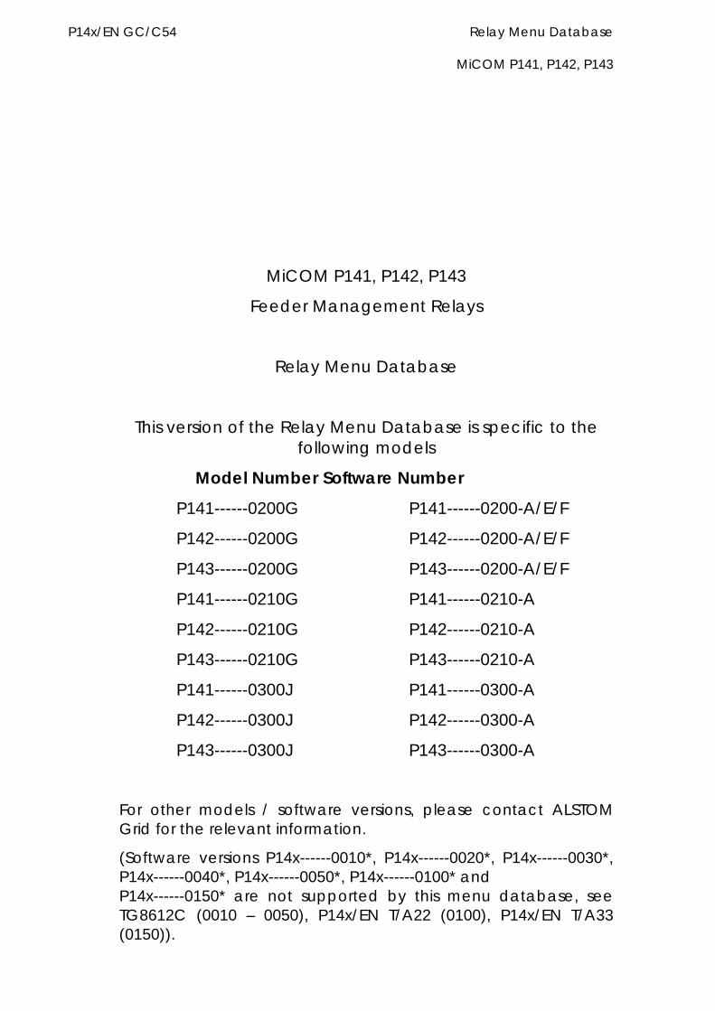
P14x/EN GC/C54 Relay Menu Database MiCOM P141, P142, P143
MiCOM P141, P142, P143
Feeder Management Relays
Relay Menu Database
This version of the Relay Menu Database is specific to the following models
Model Number Software Number
P141------0200G P141------0200-A/E/F
P142------0200G P142------0200-A/E/F
P143------0200G P143------0200-A/E/F
P141------0210G P141------0210-A
P142------0210G P142------0210-A
P143------0210G P143------0210-A
P141------0300J P141------0300-A
P142------0300J P142------0300-A
P143------0300J P143------0300-A
For other models / software versions, please contact ALSTOM Grid for the relevant information.
(Software versions P14x------0010*, P14x------0020*, P14x------0030*, P14x------0040*, P14x------0050*, P14x------0100* and P14x------0150* are not supported by this menu database, see TG8612C (0010 – 0050), P14x/EN T/A22 (0100), P14x/EN T/A33 (0150)).

Relay Menu Database P14x/EN GC/C54 MiCOM P141, P142, P143


Relay Menu Database P14x/EN GC/C54 MiCOM P141, P142, P143 Page 1/232
RELAY MENU DATABASE This Relay Menu Database is split into several sections, these are as follows:
Menu Database for Courier, User Interface and MODBUS
Menu Datatype Definition
Event Data for Courier, User Interface and MODBUS
IEC60870-5-103 Interoperability Guide
Internal Digital Signals
DNP3.0 Device Profile Document
Default Programmable Logic
Menu database
This database defines the structure of the relay menu for the courier interface, the front panel user interface and the MODBUS interface. This includes all the relay settings and measurements. Datatypes for MODBUS and indexed strings for Courier and the user interface are cross-referenced to the Menu Datatype Definition section (using a G Number). For all settable cells the setting limits and default value are also defined within this database.
Note: The following labels are used within the database
Label Description Value
V1 Main VT Rating 1 (100/110V)
V2 Checksynch VT Rating 1 (100/110V)
V3 NVD VT Rating 1 (100/110V)
1 Phase CT Rating 1 or 5 (Setting 0A08)
2 Earth Fault CT Rating 1 or 5 (Setting 0A0A)
3 Sensitive CT Rating 1 or 5 (Setting 0A0C)
4 Mutual CT Rating 1 or 5 (Setting 0A0E)
Menu datatype definition
This table defines the datatypes used for MODBUS (the datatypes for the Courier and user interface are defined within the Menu Database itself using the standard Courier Datatypes). This section also defines the indexed string setting options for all interfaces. The datatypes defined within this section are cross-referenced to from the menu Database using a G number.
Event data
This section specifies all the event information that can be produced by the relay. It details exactly how each event will be presented via the Courier, User and MODBUS interfaces.
IEC60870-5-103 interoperability guide
P14x/EN GC/C54 Relay Menu Database Page 2/232 MiCOM P141, P142, P143
This table fully defines the operation of the IEC60870-5-103 (VDEW) interface for the relay it should be read in conjunction with the relevant section of the Communications section of this Manual (P14x/EN CT).
Internal digital signals
This table defines all of the relay internal digital signals (opto inputs, output contacts and protection inputs and outputs). A relay may have up to 512 internal signals each referenced by a numeric index as shown in this table. This numeric index is used to select a signal for the commissioning monitor port. It is also used to explicitly define protection events produced by the relay (see the Event Data section).
DNP3.0 device profile document
This table defines all of the objects, functions and/or qualifiers supported.
Default programmable logic
This section documents the default programmable logic for the various models of the relay. This default logic for each model of the relay is supplied with the MiCOM S1 Scheme Logic Editor PC support software.
References
Introduction (P14x/EN IT): User Interface operation and connections to the relay
Communications (P14x/EN CT): Overview of communication interfaces
Courier User Guide R6512
Modicon MODBUS Protocol Reference Guide PI-MBUS-300 Rev E
IEC60870-5-103 Telecontrol Equipment and Systems – Transmission Protocols – Companion Standard for the informative interface of Protection Equipment
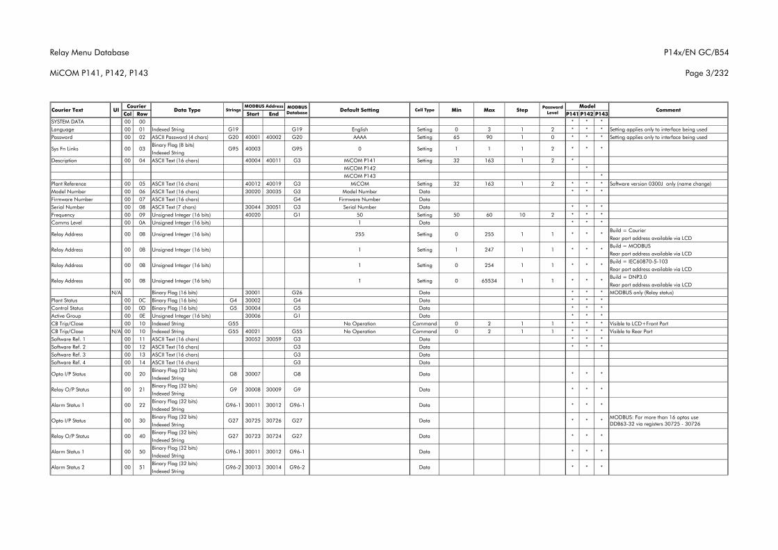
Relay Menu Database
MiCOM P141, P142, P143
P14x/EN GC/B54
Page 3/232
Col Row Start End P141 P142 P143SYSTEM DATA 00 00 * * *Language 00 01 Indexed String G19 G19 English Setting 0 3 1 2 * * * Setting applies only to interface being usedPassword 00 02 ASCII Password (4 chars) G20 40001 40002 G20 AAAA Setting 65 90 1 0 * * * Setting applies only to interface being used
Binary Flag (8 bits)Indexed String
Description 00 04 ASCII Text (16 chars) 40004 40011 G3 MiCOM P141 Setting 32 163 1 2 *MiCOM P142 *MiCOM P143 *
Plant Reference 00 05 ASCII Text (16 chars) 40012 40019 G3 MiCOM Setting 32 163 1 2 * * * Software version 0300J only (name change)Model Number 00 06 ASCII Text (16 chars) 30020 30035 G3 Model Number Data * * *Firmware Number 00 07 ASCII Text (16 chars) G4 Firmware Number DataSerial Number 00 08 ASCII Text (7 chars) 30044 30051 G3 Serial Number Data * * *Frequency 00 09 Unsigned Integer (16 bits) 40020 G1 50 Setting 50 60 10 2 * * *Comms Level 00 0A Unsigned Integer (16 bits) 1 Data * * *
Build = CourierRear port address available via LCDBuild = MODBUSRear port address available via LCDBuild = IEC60870-5-103Rear port address available via LCDBuild = DNP3.0Rear port address available via LCD
N/A Binary Flag (16 bits) 30001 G26 Data * * * MODBUS only (Relay status)Plant Status 00 0C Binary Flag (16 bits) G4 30002 G4 Data * * *Control Status 00 0D Binary Flag (16 bits) G5 30004 G5 Data * * *Active Group 00 0E Unsigned Integer (16 bits) 30006 G1 Data * * *CB Trip/Close 00 10 Indexed String G55 No Operation Command 0 2 1 1 * * * Visible to LCD+Front PortCB Trip/Close N/A 00 10 Indexed String G55 40021 G55 No Operation Command 0 2 1 1 * * * Visible to Rear PortSoftware Ref. 1 00 11 ASCII Text (16 chars) 30052 30059 G3 Data * * *Software Ref. 2 00 12 ASCII Text (16 chars) G3 Data * * *Software Ref. 3 00 13 ASCII Text (16 chars) G3 DataSoftware Ref. 4 00 14 ASCII Text (16 chars) G3 Data
Binary Flag (32 bits)Indexed StringBinary Flag (32 bits)Indexed StringBinary Flag (32 bits)Indexed StringBinary Flag (32 bits)Indexed StringBinary Flag (32 bits)Indexed StringBinary Flag (32 bits)Indexed StringBinary Flag (32 bits)Indexed String
Alarm Status 1 30011 30012 G96-100 50 G96-1
Relay O/P Status 30723 30724 G2700 40 G27
Opto I/P Status 30725 30726 G2700 30 G27
Alarm Status 1 30011 30012 G96-100 22 G96-1
Relay O/P Status 30008 * *00 21 G9 30009 G9
Opto I/P Status 00 20 DataG8 30007 G8
* * *1 1 1 240003 G95 0 SettingSys Fn Links 00 03 G95
*
*
*
*
*
*
*
*
*
1 1
1
* *
* *
255
247
254
65534
0
1
0
0
Setting
Setting
Setting
Setting
Relay Address
Relay Address
Relay Address
Relay Address
Courier Text UI Data Type StringsCourier
CommentMODBUS Database Default Setting Cell Type Min
MODBUS Address ModelMax Step Password
Level
Data
Data * *
Data * *
Data * *
Data * *
Alarm Status 2 00 51 G96-2 30013 30014 G96-2 Data * * *
00 0B Unsigned Integer (16 bits) 255
00 0B Unsigned Integer (16 bits) 1 1 * * *
00 0B Unsigned Integer (16 bits) 1 1 1 * *
00 0B Unsigned Integer (16 bits) 1 1 1 * *
MODBUS: For more than 16 optos use DDB63-32 via registers 30725 - 30726
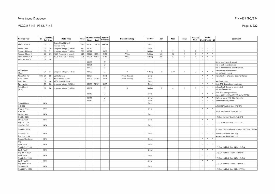
Relay Menu Database
MiCOM P141, P142, P143
P14x/EN GC/B54
Page 4/232
Col Row Start End P141 P142 P143Courier Text UI Data Type Strings
CourierCommentMODBUS
Database Default Setting Cell Type MinMODBUS Address Model
Max Step Password Level
Binary Flag (32 bits)Indexed String
Access Level 00 D0 Unsigned Integer (16 bits) G1 30010 G1 Data * * *Password Control 00 D1 Unsigned Integer (16 bits) G22 40022 G22 2 Setting 0 2 1 2 * * *Password Level 1 00 D2 ASCII Password (4 chars) G20 40023 40024 G20 AAAA Setting 65 90 1 1 * * *Password Level 2 00 D3 ASCII Password (4 chars) G20 40025 40026 G20 AAAA Setting 65 90 1 2 * * *VIEW RECORDS 01 00 * * *
30100 G1 No of event records stored30101 G1 No of fault records stored30102 G1 No of maintenance records stored
Select Event [0...n]
01 01 Unsigned Integer (16 bits) 40100 G1 0 Setting 0 249 1 0 * * *Max value is oldest record n is last event record
Menu Cell Ref N/A 01 02 Cell Reference 30107 G13 (From Record) Data * * * Indicates type of event. See event sheet Time & Date 01 03 IEC870 Date & Time 30103 30106 G12 (From Record) Data * * *Event Text 01 04 ASCII Text (32 chars) Data * * * See Event sheetEvent Value 01 05 Unsigned Integer (32 bits) 30108 30109 G27 Data * * * Note DTL depends on event type
Select Event [0...n]
01 06 Unsigned Integer (16 bits) 40101 G1 0 Setting 0 4 1 0 * * *Allows Fault Record to be selected n is last fault record
30110 G1 Data * * *MODBUS change address Alarm 30011, Relay 30723, Opto 30725
30111 G1 Data * * * Status of current 16 ddb elements30112 G1 Data * * * Additional data present
Started Phase N/A Data * * *A B C N A/B/C/N Visible if Start A/B/C/NTripped Phase N/A Data * * *A B C N A/B/C/N Visible if Trip A/B/C/NOvercurrent N/A Data * * *Start I> 1234 1/2/3/4 Visible if Start I>1/2/3/4Overcurrent N/A Data * * *Trip I> 1234 1/2/3/4 Visible if Trip I>1/2/3/4Neg Seq O/C N/A Data * * *
Start I2> 1234 I2>Start Trip in software versions 0200G & 0210G
Neg Seq O/C N/A Data * * * Software version 0300J onlyTrip I2> 1234 Software version 0300J onlyBroken Conductor N/A Data * * *TripEarth Fault 1 N/A Data * * *Start IN1> 1234 1/2/3/4 visible if Start IN1>1/2/3/4Earth Fault 1 N/A Data * * *Trip IN1> 1234 1/2/3/4 visible if Trip IN1>1/2/3/4Earth Fault 2 N/A Data * * *Start IN2> 1234 1/2/3/4 visible if Start IN2>1/2/3/4Earth Fault 2 N/A Data * * *Trip IN2> 1234 1/2/3/4 visible if Trip IN2>1/2/3/4Sensitive E/F N/A Data * * *Start ISEF> 1234 1/2/3/4 visible if Start ISEF>1/2/3/4
Alarm Status 3 00 51 G96-3 30015 30016 G96-3 Data * * *
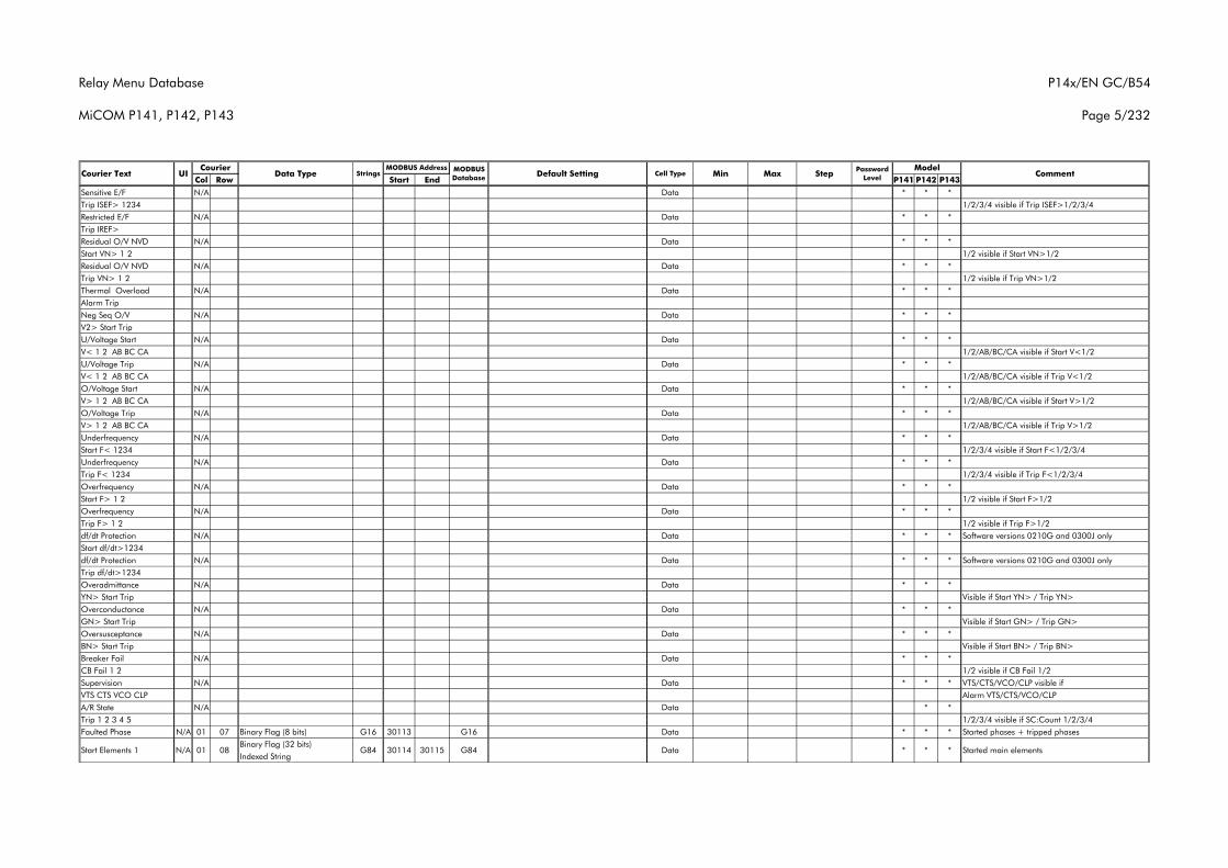
Relay Menu Database
MiCOM P141, P142, P143
P14x/EN GC/B54
Page 5/232
Col Row Start End P141 P142 P143Courier Text UI Data Type Strings
CourierCommentMODBUS
Database Default Setting Cell Type MinMODBUS Address Model
Max Step Password Level
Sensitive E/F N/A Data * * *Trip ISEF> 1234 1/2/3/4 visible if Trip ISEF>1/2/3/4Restricted E/F N/A Data * * *Trip IREF>Residual O/V NVD N/A Data * * *Start VN> 1 2 1/2 visible if Start VN>1/2Residual O/V NVD N/A Data * * *Trip VN> 1 2 1/2 visible if Trip VN>1/2Thermal Overload N/A Data * * *Alarm TripNeg Seq O/V N/A Data * * *V2> Start TripU/Voltage Start N/A Data * * *V< 1 2 AB BC CA 1/2/AB/BC/CA visible if Start V<1/2U/Voltage Trip N/A Data * * *V< 1 2 AB BC CA 1/2/AB/BC/CA visible if Trip V<1/2O/Voltage Start N/A Data * * *V> 1 2 AB BC CA 1/2/AB/BC/CA visible if Start V>1/2O/Voltage Trip N/A Data * * *V> 1 2 AB BC CA 1/2/AB/BC/CA visible if Trip V>1/2Underfrequency N/A Data * * *Start F< 1234 1/2/3/4 visible if Start F<1/2/3/4Underfrequency N/A Data * * *Trip F< 1234 1/2/3/4 visible if Trip F<1/2/3/4Overfrequency N/A Data * * *Start F> 1 2 1/2 visible if Start F>1/2Overfrequency N/A Data * * *Trip F> 1 2 1/2 visible if Trip F>1/2df/dt Protection N/A Data * * * Software versions 0210G and 0300J onlyStart df/dt>1234df/dt Protection N/A Data * * * Software versions 0210G and 0300J onlyTrip df/dt>1234Overadmittance N/A Data * * *YN> Start Trip Visible if Start YN> / Trip YN>Overconductance N/A Data * * *GN> Start Trip Visible if Start GN> / Trip GN>Oversusceptance N/A Data * * *BN> Start Trip Visible if Start BN> / Trip BN>Breaker Fail N/A Data * * *CB Fail 1 2 1/2 visible if CB Fail 1/2Supervision N/A Data * * * VTS/CTS/VCO/CLP visible if VTS CTS VCO CLP Alarm VTS/CTS/VCO/CLPA/R State N/A Data * *Trip 1 2 3 4 5 1/2/3/4 visible if SC:Count 1/2/3/4Faulted Phase N/A 01 07 Binary Flag (8 bits) G16 30113 G16 Data * * * Started phases + tripped phases
Binary Flag (32 bits)Indexed String
***G84 DataG84 30114 30115Start Elements 1 N/A 01 08 Started main elements
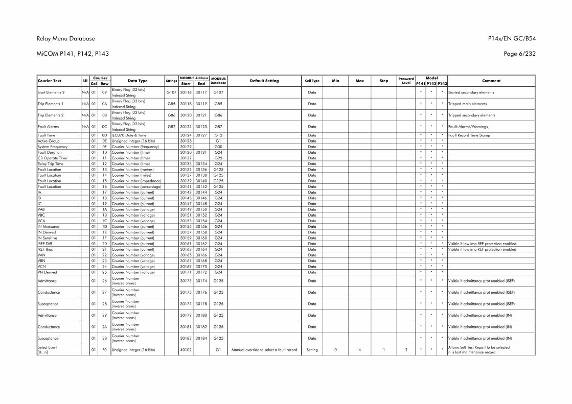
Relay Menu Database
MiCOM P141, P142, P143
P14x/EN GC/B54
Page 6/232
Col Row Start End P141 P142 P143Courier Text UI Data Type Strings
CourierCommentMODBUS
Database Default Setting Cell Type MinMODBUS Address Model
Max Step Password Level
Binary Flag (32 bits)Indexed StringBinary Flag (32 bits)Indexed StringBinary Flag (32 bits)Indexed StringBinary Flag (32 bits)Indexed String
Fault Time 01 0D IEC870 Date & Time 30124 30127 G12 Data * * * Fault Record Time StampActive Group 01 0E Unsigned Integer (16 bits) 30128 G1 Data * * *System Frequency 01 0F Courier Number (frequency) 30129 G30 Data * * *Fault Duration 01 10 Courier Number (time) 30130 30131 G24 Data * * *CB Operate Time 01 11 Courier Number (time) 30132 G25 Data * * *Relay Trip Time 01 12 Courier Number (time) 30133 30134 G24 Data * * *Fault Location 01 13 Courier Number (metres) 30135 30136 G125 Data * * *Fault Location 01 14 Courier Number (miles) 30137 30138 G125 Data * * *Fault Location 01 15 Courier Number (impedance) 30139 30140 G125 Data * * *Fault Location 01 16 Courier Number (percentage) 30141 30142 G125 Data * * *IA 01 17 Courier Number (current) 30143 30144 G24 Data * * *IB 01 18 Courier Number (current) 30145 30146 G24 Data * * *IC 01 19 Courier Number (current) 30147 30148 G24 Data * * *VAB 01 1A Courier Number (voltage) 30149 30150 G24 Data * * *VBC 01 1B Courier Number (voltage) 30151 30152 G24 Data * * *VCA 01 1C Courier Number (voltage) 30153 30154 G24 Data * * *IN Measured 01 1D Courier Number (current) 30155 30156 G24 Data * * *IN Derived 01 1E Courier Number (current) 30157 30158 G24 Data * * *IN Sensitive 01 1F Courier Number (current) 30159 30160 G24 Data * * *IREF Diff 01 20 Courier Number (current) 30161 30162 G24 Data * * * Visible if low imp REF protection enabledIREF Bias 01 21 Courier Number (current) 30163 30164 G24 Data * * * Visible if low imp REF protection enabledVAN 01 22 Courier Number (voltage) 30165 30166 G24 Data * * *VBN 01 23 Courier Number (voltage) 30167 30168 G24 Data * * *VCN 01 24 Courier Number (voltage) 30169 30170 G24 Data * * *VN Derived 01 25 Courier Number (voltage) 30171 30172 G24 Data * * *
Admittance 01 26Courier Number (inverse ohms)
30173 30174 G125 Data * * * Visible if admittance prot enabled (ISEF)
Conductance 01 27Courier Number (inverse ohms)
30175 30176 G125 Data * * * Visible if admittance prot enabled (ISEF)
Susceptance 01 28Courier Number (inverse ohms)
30177 30178 G125 Data * * * Visible if admittance prot enabled (ISEF)
Admittance 01 29Courier Number (inverse ohms)
30179 30180 G125 Data * * * Visible if admittance prot enabled (IN)
Conductance 01 2ACourier Number (inverse ohms)
30181 30182 G125 Data * * * Visible if admittance prot enabled (IN)
Susceptance 01 2BCourier Number (inverse ohms)
30183 30184 G125 Data * * * Visible if admittance prot enabled (IN)
Select Event [0...n]
01 F0 Unsigned Integer (16 bits) 40102 G1 Manual override to select a fault record Setting 0 4 1 2 * * *Allows Self Test Report to be selected n is last maintenance record
30121
* * *
Trip Elements 2 N/A 01 0B G86 30120
30119 G85 Data
* * *
Trip Elements 1 N/A 01 0A G85 30118
G107 G107 Data30116 30117Start Elements 2 N/A 01 09
G86 Data *
G87 30122 30123Fault Alarms N/A 01 0C G87 Data * * *
Started secondary elements
Tripped main elements
Tripped secondary elements
Faullt Alarms/Warnings
* *
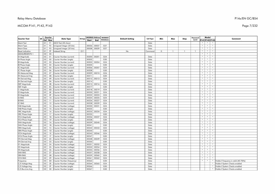
Relay Menu Database
MiCOM P141, P142, P143
P14x/EN GC/B54
Page 7/232
Col Row Start End P141 P142 P143Courier Text UI Data Type Strings
CourierCommentMODBUS
Database Default Setting Cell Type MinMODBUS Address Model
Max Step Password Level
Maint Text 01 F1 ASCII Text (32 chars) Data * * *Maint Type 01 F2 Unsigned Integer (32 bits) 30036 30037 G27 Data * * *Maint Data 01 F3 Unsigned Integer (32 bits) 30038 30039 G27 Data * * *Reset Indication 01 FF Indexed String G11 No Command 0 1 1 1 * * *MEASUREMENTS 1 02 00 * * *IA Magnitude 02 01 Courier Number (current) 30200 30201 G24 Data * * *IA Phase Angle 02 02 Courier Number (angle) 30202 G30 Data * * *IB Magnitude 02 03 Courier Number (current) 30203 30204 G24 Data * * *IB Phase Angle 02 04 Courier Number (angle) 30205 G30 Data * * *IC Magnitude 02 05 Courier Number (current) 30206 30207 G24 Data * * *IC Phase Angle 02 06 Courier Number (angle) 30208 G30 Data * * *IN Measured Mag 02 07 Courier Number (current) 30209 30210 G24 Data * * *IN Measured Ang 02 08 Courier Number (angle) 30211 G30 Data * * *IN Derived Mag 02 09 Courier Number (current) 30212 30213 G24 Data * * *IN Derived Angle 02 0A Courier Number (angle) 30214 G30 Data * * *ISEF Magnitude 02 0B Courier Number (current) 30215 30216 G24 Data * * *ISEF Angle 02 0C Courier Number (angle) 30217 G30 Data * * *I1 Magnitude 02 0D Courier Number (current) 30218 30219 G24 Data * * *I2 Magnitude 02 0E Courier Number (current) 30220 30221 G24 Data * * *I0 Magnitude 02 0F Courier Number (current) 30222 30223 G24 Data * * *IA RMS 02 10 Courier Number (current) 30224 30225 G24 Data * * *IB RMS 02 11 Courier Number (current) 30226 30227 G24 Data * * *IC RMS 02 12 Courier Number (current) 30228 30229 G24 Data * * *VAB Magnitude 02 14 Courier Number (voltage) 30230 30231 G24 Data * * *VAB Phase Angle 02 15 Courier Number (angle) 30232 G30 Data * * *VBC Magnitude 02 16 Courier Number (voltage) 30233 30234 G24 Data * * *VBC Phase Angle 02 17 Courier Number (angle) 30235 G30 Data * * *VCA Magnitude 02 18 Courier Number (voltage) 30236 30237 G24 Data * * *VCA Phase Angle 02 19 Courier Number (angle) 30238 G30 Data * * *VAN Magnitude 02 1A Courier Number (voltage) 30239 30240 G24 Data * * *VAN Phase Angle 02 1B Courier Number (angle) 30241 G30 Data * * *VBN Magnitude 02 1C Courier Number (voltage) 30242 30243 G24 Data * * *VBN Phase Angle 02 1D Courier Number (angle) 30244 G30 Data * * *VCN Magnitude 02 1E Courier Number (voltage) 30245 30246 G24 Data * * *VCN Phase Angle 02 1F Courier Number (angle) 30247 G30 Data * * *VN Derived Mag 02 22 Courier Number (voltage) 30248 30249 G24 Data * * *VN Derived Ang 02 23 Courier Number (angle) 30250 G30 Data * * *V1 Magnitude 02 24 Courier Number (voltage) 30251 30252 G24 Data * * *V2 Magnitude 02 25 Courier Number (voltage) 30253 30254 G24 Data * * *V0 Magnitude 02 26 Courier Number (voltage) 30255 30256 G24 Data * * *VAN RMS 02 27 Courier Number (voltage) 30257 30258 G24 Data * * *VBN RMS 02 28 Courier Number (voltage) 30259 30260 G24 Data * * *VCN RMS 02 29 Courier Number (voltage) 30261 30262 G24 Data * * *Frequency 02 2D Courier Number (frequency) 30263 G30 Data * * * Visible if frequency is valid (40-70Hz)C/S Voltage Mag 02 2E Courier Number (voltage) 30264 30265 G24 Data * Visible if System Checks enabledC/S Voltage Ang 02 2F Courier Number (angle) 30266 G30 Data * Visible if System Checks enabledC/S Bus-Line Ang 02 30 Courier Number (angle) 30267 G30 Data * Visible if System Checks enabled
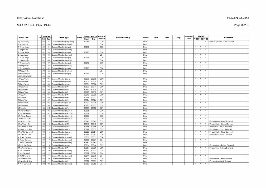
Relay Menu Database
MiCOM P141, P142, P143
P14x/EN GC/B54
Page 8/232
Col Row Start End P141 P142 P143Courier Text UI Data Type Strings
CourierCommentMODBUS
Database Default Setting Cell Type MinMODBUS Address Model
Max Step Password Level
Slip Frequency 02 31 Courier Number (frequency) 30268 G30 Data * Visible if System Checks enabledI1 Magnitude 02 40 Courier Number (current) G24 Data * * *I1 Phase Angle 02 41 Courier Number (angle) 30269 G30 Data * * *I2 Magnitude 02 42 Courier Number (current) G24 Data * * *I2 Phase Angle 02 43 Courier Number (angle) 30270 G30 Data * * *I0 Magnitude 02 44 Courier Number (current) G24 Data * * *I0 Phase Angle 02 45 Courier Number (angle) 30271 G30 Data * * *V1 Magnitude 02 46 Courier Number (voltage) G24 Data * * *V1 Phase Angle 02 47 Courier Number (angle) 30272 G30 Data * * *V2 Magnitude 02 48 Courier Number (voltage) G24 Data * * *V2 Phase Angle 02 49 Courier Number (angle) 30273 G30 Data * * *V0 Magnitude 02 4A Courier Number (voltage) G24 Data * * *V0 Phase Angle 02 4B Courier Number (angle) 30274 G30 Data * * *MEASUREMENTS 2 03 00 * * *A Phase Watts 03 01 Courier Number (power) 30300 30302 G29 Data * * *B Phase Watts 03 02 Courier Number (power) 30303 30305 G29 Data * * *C Phase Watts 03 03 Courier Number (power) 30306 30308 G29 Data * * *A Phase VArs 03 04 Courier Number (VAr) 30309 30311 G29 Data * * *B Phase VArs 03 05 Courier Number (VAr) 30312 30314 G29 Data * * *C Phase VArs 03 06 Courier Number (VAr) 30315 30317 G29 Data * * *A Phase VA 03 07 Courier Number (VA) 30318 30320 G29 Data * * *B Phase VA 03 08 Courier Number (VA) 30321 30323 G29 Data * * *C Phase VA 03 09 Courier Number (VA) 30324 30326 G29 Data * * *3 Phase Watts 03 0A Courier Number (power) 30327 30329 G29 Data * * *3 Phase VArs 03 0B Courier Number (VAr) 30330 30332 G29 Data * * *3 Phase VA 03 0C Courier Number (VA) 30333 30335 G29 Data * * *3Ph Power Factor 03 0E Courier Number (decimal) 30336 G30 Data * * *APh Power Factor 03 0F Courier Number (decimal) 30337 G30 Data * * *BPh Power Factor 03 10 Courier Number (decimal) 30338 G30 Data * * *CPh Power Factor 03 11 Courier Number (decimal) 30339 G30 Data * * *3Ph WHours Fwd 03 12 Courier Number (Wh) 30340 30342 G29 Data * * * 3 Phase Watt - Hours (Forward)3Ph WHours Rev 03 13 Courier Number (Wh) 30343 30345 G29 Data * * * 3 Phase Watts - Hours (Reverse)3Ph VArHours Fwd 03 14 Courier Number (VArh) 30346 30348 G29 Data * * * 3 Phase VAr - Hours (Forward)3Ph VArHours Rev 03 15 Courier Number (VArh) 30349 30351 G29 Data * * * 3 Phase VAr - Hours (Reverse)3Ph W Fix Demand 03 16 Courier Number (power) 30352 30354 G29 Data * * * 3 Phase Watts - Fixed Demand3Ph VArs Fix Dem 03 17 Courier Number (VAr) 30355 30357 G29 Data * * * 3 Phase VArs - Fixed DemandIA Fixed Demand 03 18 Courier Number (current) 30358 30359 G24 Data * * *IB Fixed Demand 03 19 Courier Number (current) 30360 30361 G24 Data * * *IC Fixed Demand 03 1A Courier Number (current) 30362 30363 G24 Data * * *3 Ph W Roll Dem 03 1B Courier Number (power) 30364 30366 G29 Data * * * 3 Phase Watts - Rolling Demand3Ph VArs RollDem 03 1C Courier Number (VAr) 30367 30369 G29 Data * * * 3 Phase VArs - Rolling DemandIA Roll Demand 03 1D Courier Number (current) 30370 30371 G24 Data * * *IB Roll Demand 03 1E Courier Number (current) 30372 30373 G24 Data * * *IC Roll Demand 03 1F Courier Number (current) 30374 30375 G24 Data * * *3Ph W Peak Dem 03 20 Courier Number (power) 30376 30378 G29 Data * * * 3 Phase Watts - Peak Demand3Ph VAr Peak Dem 03 21 Courier Number (VAr) 30379 30381 G29 Data * * * 3 Phase VArs - Peak DemandIA Peak Demand 03 22 Courier Number (current) 30382 30383 G24 Data * * *
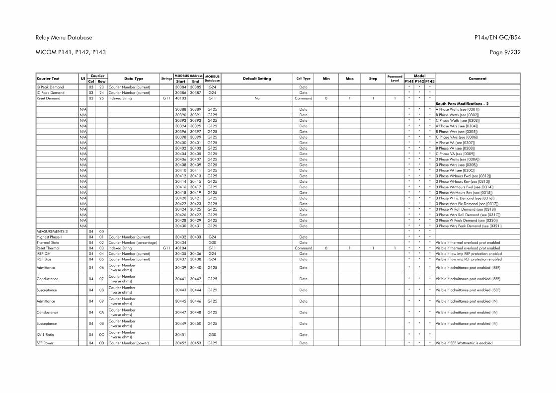
Relay Menu Database
MiCOM P141, P142, P143
P14x/EN GC/B54
Page 9/232
Col Row Start End P141 P142 P143Courier Text UI Data Type Strings
CourierCommentMODBUS
Database Default Setting Cell Type MinMODBUS Address Model
Max Step Password Level
IB Peak Demand 03 23 Courier Number (current) 30384 30385 G24 Data * * *IC Peak Demand 03 24 Courier Number (current) 30386 30387 G24 Data * * *Reset Demand 03 25 Indexed String G11 40103 G11 No Command 0 1 1 1 * * *
South Pars Modifications - 2N/A 30388 30389 G125 Data * * * A Phase Watts (see [0301]) N/A 30390 30391 G125 Data * * * B Phase Watts (see [0302]) N/A 30392 30393 G125 Data * * * C Phase Watts (see [0303]) N/A 30394 30395 G125 Data * * * A Phase VArs (see [0304]) N/A 30396 30397 G125 Data * * * B Phase VArs (see [0305]) N/A 30398 30399 G125 Data * * * C Phase VArs (see [0306]) N/A 30400 30401 G125 Data * * * A Phase VA (see [0307]) N/A 30402 30403 G125 Data * * * B Phase VA (see [0308]) N/A 30404 30405 G125 Data * * * C Phase VA (see [0309]) N/A 30406 30407 G125 Data * * * 3 Phase Watts (see [030A]) N/A 30408 30409 G125 Data * * * 3 Phase VArs (see [030B]) N/A 30410 30411 G125 Data * * * 3 Phase VA (see [030C]) N/A 30412 30413 G125 Data * * * 3 Phase WHours Fwd (see [0312]) N/A 30414 30415 G125 Data * * * 3 Phase WHours Rev (see [0313]) N/A 30416 30417 G125 Data * * * 3 Phase VArHours Fwd (see [0314]) N/A 30418 30419 G125 Data * * * 3 Phase VArHours Rev (see [0315]) N/A 30420 30421 G125 Data * * * 3 Phase W Fix Demand (see [0316]) N/A 30422 30423 G125 Data * * * 3 Phase VArs Fix Demand (see [0317]) N/A 30424 30425 G125 Data * * * 3 Phase W Roll Demand (see [031B]) N/A 30426 30427 G125 Data * * * 3 Phase VArs Roll Demand (see [031C]) N/A 30428 30429 G125 Data * * * 3 Phase W Peak Demand (see [0320]) N/A 30430 30431 G125 Data * * * 3 Phase VArs Peak Demand (see [0321])
MEASUREMENTS 3 04 00 * * *Highest Phase I 04 01 Courier Number (current) 30432 30433 G24 Data * * *Thermal State 04 02 Courier Number (percentage) 30434 G30 Data * * * Visible if thermal overload prot enabledReset Thermal 04 03 Indexed String G11 40104 G11 Command 0 1 1 1 * * * Visible if thermal overload prot enabledIREF Diff 04 04 Courier Number (current) 30435 30436 G24 Data * * * Visible if low imp REF protection enabledIREF Bias 04 05 Courier Number (current) 30437 30438 G24 Data * * * Visible if low imp REF protection enabled
Admittance 04 06Courier Number (inverse ohms)
30439 30440 G125 Data * * * Visible if admittance prot enabled (ISEF)
Conductance 04 07Courier Number (inverse ohms)
30441 30442 G125 Data * * * Visible if admittance prot enabled (ISEF)
Susceptance 04 08Courier Number (inverse ohms)
30443 30444 G125 Data * * * Visible if admittance prot enabled (ISEF)
Admittance 04 09Courier Number (inverse ohms)
30445 30446 G125 Data * * * Visible if admittance prot enabled (IN)
Conductance 04 0ACourier Number (inverse ohms)
30447 30448 G125 Data * * * Visible if admittance prot enabled (IN)
Susceptance 04 0BCourier Number (inverse ohms)
30449 30450 G125 Data * * * Visible if admittance prot enabled (IN)
I2/I1 Ratio 04 0CCourier Number (inverse ohms)
30451 G30 Data * * *
SEF Power 04 0D Courier Number (power) 30452 30453 G125 Data * * * Visible if SEF Wattmetric is enabled
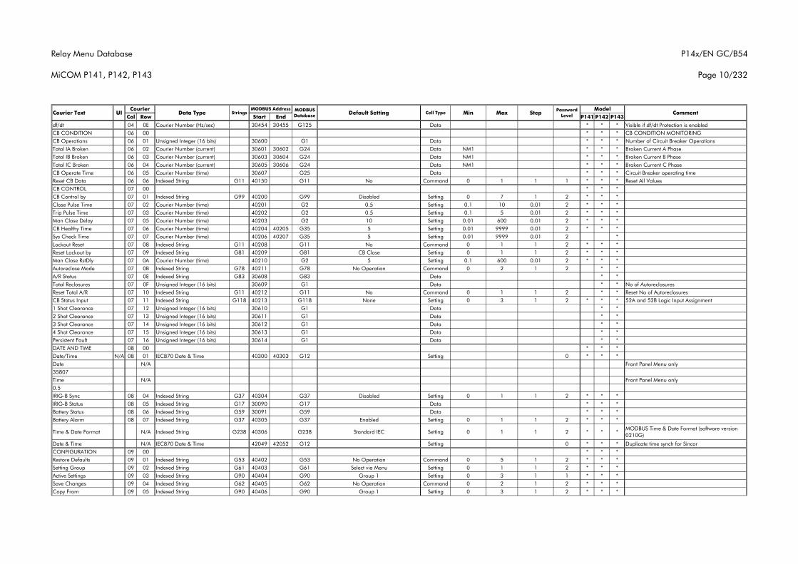
Relay Menu Database
MiCOM P141, P142, P143
P14x/EN GC/B54
Page 10/232
Col Row Start End P141 P142 P143Courier Text UI Data Type Strings
CourierCommentMODBUS
Database Default Setting Cell Type MinMODBUS Address Model
Max Step Password Level
df/dt 04 0E Courier Number (Hz/sec) 30454 30455 G125 Data * * * Visible if df/dt Protection is enabledCB CONDITION 06 00 * * * CB CONDITION MONITORINGCB Operations 06 01 Unsigned Integer (16 bits) 30600 G1 Data * * * Number of Circuit Breaker OperationsTotal IA Broken 06 02 Courier Number (current) 30601 30602 G24 Data NM1 * * * Broken Current A PhaseTotal IB Broken 06 03 Courier Number (current) 30603 30604 G24 Data NM1 * * * Broken Current B PhaseTotal IC Broken 06 04 Courier Number (current) 30605 30606 G24 Data NM1 * * * Broken Current C PhaseCB Operate Time 06 05 Courier Number (time) 30607 G25 Data * * * Circuit Breaker operating timeReset CB Data 06 06 Indexed String G11 40150 G11 No Command 0 1 1 1 * * * Reset All ValuesCB CONTROL 07 00 * * *CB Control by 07 01 Indexed String G99 40200 G99 Disabled Setting 0 7 1 2 * * *Close Pulse Time 07 02 Courier Number (time) 40201 G2 0.5 Setting 0.1 10 0.01 2 * * *Trip Pulse Time 07 03 Courier Number (time) 40202 G2 0.5 Setting 0.1 5 0.01 2 * * *Man Close Delay 07 05 Courier Number (time) 40203 G2 10 Setting 0.01 600 0.01 2 * * *CB Healthy Time 07 06 Courier Number (time) 40204 40205 G35 5 Setting 0.01 9999 0.01 2 * * *Sys Check Time 07 07 Courier Number (time) 40206 40207 G35 5 Setting 0.01 9999 0.01 2 *Lockout Reset 07 08 Indexed String G11 40208 G11 No Command 0 1 1 2 * * *Reset Lockout by 07 09 Indexed String G81 40209 G81 CB Close Setting 0 1 1 2 * * *Man Close RstDly 07 0A Courier Number (time) 40210 G2 5 Setting 0.1 600 0.01 2 * * *Autoreclose Mode 07 0B Indexed String G78 40211 G78 No Operation Command 0 2 1 2 * *A/R Status 07 0E Indexed String G83 30608 G83 Data * *Total Reclosures 07 0F Unsigned Integer (16 bits) 30609 G1 Data * * No of AutoreclosuresReset Total A/R 07 10 Indexed String G11 40212 G11 No Command 0 1 1 2 * * Reset No of AutoreclosuresCB Status Input 07 11 Indexed String G118 40213 G118 None Setting 0 3 1 2 * * * 52A and 52B Logic Input Assignment 1 Shot Clearance 07 12 Unsigned Integer (16 bits) 30610 G1 Data * *2 Shot Clearance 07 13 Unsigned Integer (16 bits) 30611 G1 Data * *3 Shot Clearance 07 14 Unsigned Integer (16 bits) 30612 G1 Data * *4 Shot Clearance 07 15 Unsigned Integer (16 bits) 30613 G1 Data * *Persistent Fault 07 16 Unsigned Integer (16 bits) 30614 G1 Data * *DATE AND TIME 08 00 * * *Date/Time N/A 08 01 IEC870 Date & Time 40300 40303 G12 Setting 0 * * *Date N/A Front Panel Menu only35807Time N/A Front Panel Menu only0.5IRIG-B Sync 08 04 Indexed String G37 40304 G37 Disabled Setting 0 1 1 2 * * *IRIG-B Status 08 05 Indexed String G17 30090 G17 Data * * *Battery Status 08 06 Indexed String G59 30091 G59 Data * * *Battery Alarm 08 07 Indexed String G37 40305 G37 Enabled Setting 0 1 1 2 * * *
Time & Date Format N/A Indexed String G238 40306 G238 Standard IEC Setting 0 1 1 2 * * *MODBUS Time & Date Format (software version 0210G)
Date & Time N/A IEC870 Date & Time 42049 42052 G12 Setting 0 * * * Duplicate time synch for SincorCONFIGURATION 09 00 * * *Restore Defaults 09 01 Indexed String G53 40402 G53 No Operation Command 0 5 1 2 * * *Setting Group 09 02 Indexed String G61 40403 G61 Select via Menu Setting 0 1 1 2 * * *Active Settings 09 03 Indexed String G90 40404 G90 Group 1 Setting 0 3 1 1 * * *Save Changes 09 04 Indexed String G62 40405 G62 No Operation Command 0 2 1 2 * * *Copy From 09 05 Indexed String G90 40406 G90 Group 1 Setting 0 3 1 2 * * *
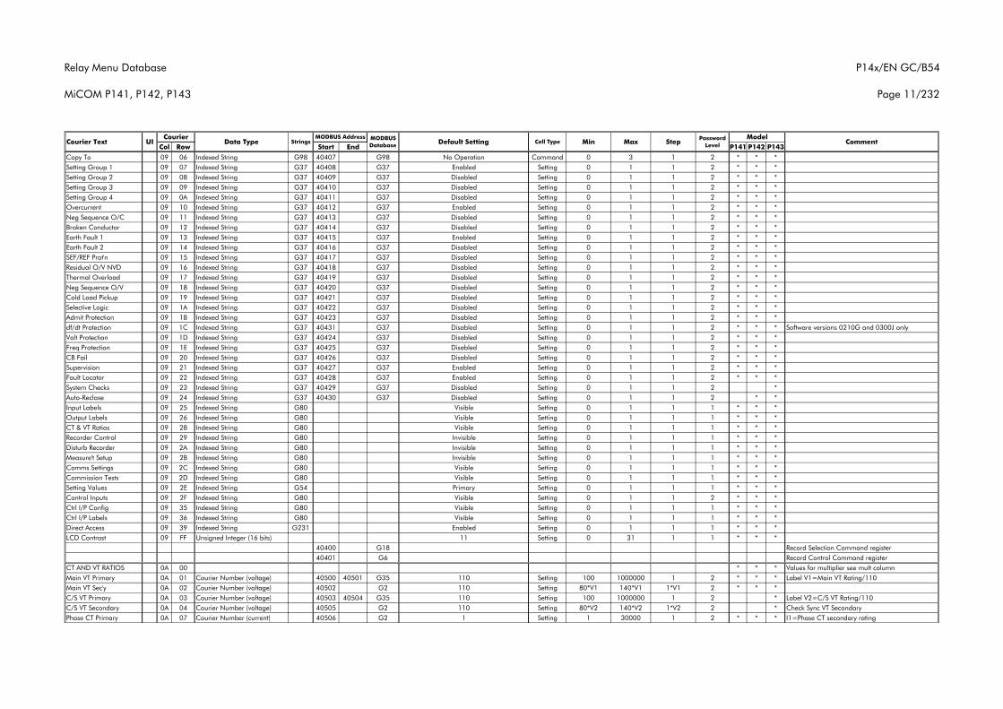
Relay Menu Database
MiCOM P141, P142, P143
P14x/EN GC/B54
Page 11/232
Col Row Start End P141 P142 P143Courier Text UI Data Type Strings
CourierCommentMODBUS
Database Default Setting Cell Type MinMODBUS Address Model
Max Step Password Level
Copy To 09 06 Indexed String G98 40407 G98 No Operation Command 0 3 1 2 * * *Setting Group 1 09 07 Indexed String G37 40408 G37 Enabled Setting 0 1 1 2 * * *Setting Group 2 09 08 Indexed String G37 40409 G37 Disabled Setting 0 1 1 2 * * *Setting Group 3 09 09 Indexed String G37 40410 G37 Disabled Setting 0 1 1 2 * * *Setting Group 4 09 0A Indexed String G37 40411 G37 Disabled Setting 0 1 1 2 * * *Overcurrent 09 10 Indexed String G37 40412 G37 Enabled Setting 0 1 1 2 * * *Neg Sequence O/C 09 11 Indexed String G37 40413 G37 Disabled Setting 0 1 1 2 * * *Broken Conductor 09 12 Indexed String G37 40414 G37 Disabled Setting 0 1 1 2 * * *Earth Fault 1 09 13 Indexed String G37 40415 G37 Enabled Setting 0 1 1 2 * * *Earth Fault 2 09 14 Indexed String G37 40416 G37 Disabled Setting 0 1 1 2 * * *SEF/REF Prot'n 09 15 Indexed String G37 40417 G37 Disabled Setting 0 1 1 2 * * *Residual O/V NVD 09 16 Indexed String G37 40418 G37 Disabled Setting 0 1 1 2 * * *Thermal Overload 09 17 Indexed String G37 40419 G37 Disabled Setting 0 1 1 2 * * *Neg Sequence O/V 09 18 Indexed String G37 40420 G37 Disabled Setting 0 1 1 2 * * *Cold Load Pickup 09 19 Indexed String G37 40421 G37 Disabled Setting 0 1 1 2 * * *Selective Logic 09 1A Indexed String G37 40422 G37 Disabled Setting 0 1 1 2 * * *Admit Protection 09 1B Indexed String G37 40423 G37 Disabled Setting 0 1 1 2 * * *df/dt Protection 09 1C Indexed String G37 40431 G37 Disabled Setting 0 1 1 2 * * * Software versions 0210G and 0300J onlyVolt Protection 09 1D Indexed String G37 40424 G37 Disabled Setting 0 1 1 2 * * *Freq Protection 09 1E Indexed String G37 40425 G37 Disabled Setting 0 1 1 2 * * *CB Fail 09 20 Indexed String G37 40426 G37 Disabled Setting 0 1 1 2 * * *Supervision 09 21 Indexed String G37 40427 G37 Enabled Setting 0 1 1 2 * * *Fault Locator 09 22 Indexed String G37 40428 G37 Enabled Setting 0 1 1 2 * * *System Checks 09 23 Indexed String G37 40429 G37 Disabled Setting 0 1 1 2 *Auto-Reclose 09 24 Indexed String G37 40430 G37 Disabled Setting 0 1 1 2 * *Input Labels 09 25 Indexed String G80 Visible Setting 0 1 1 1 * * *Output Labels 09 26 Indexed String G80 Visible Setting 0 1 1 1 * * *CT & VT Ratios 09 28 Indexed String G80 Visible Setting 0 1 1 1 * * *Recorder Control 09 29 Indexed String G80 Invisible Setting 0 1 1 1 * * *Disturb Recorder 09 2A Indexed String G80 Invisible Setting 0 1 1 1 * * *Measure't Setup 09 2B Indexed String G80 Invisible Setting 0 1 1 1 * * *Comms Settings 09 2C Indexed String G80 Visible Setting 0 1 1 1 * * *Commission Tests 09 2D Indexed String G80 Visible Setting 0 1 1 1 * * *Setting Values 09 2E Indexed String G54 Primary Setting 0 1 1 1 * * *Control Inputs 09 2F Indexed String G80 Visible Setting 0 1 1 2 * * *Ctrl I/P Config 09 35 Indexed String G80 Visible Setting 0 1 1 1 * * *Ctrl I/P Labels 09 36 Indexed String G80 Visible Setting 0 1 1 1 * * *Direct Access 09 39 Indexed String G231 Enabled Setting 0 1 1 1 * * *LCD Contrast 09 FF Unsigned Integer (16 bits) 11 Setting 0 31 1 1 * * *
40400 G18 Record Selection Command register40401 G6 Record Control Command register
CT AND VT RATIOS 0A 00 * * * Values for multiplier see mult columnMain VT Primary 0A 01 Courier Number (voltage) 40500 40501 G35 110 Setting 100 1000000 1 2 * * * Label V1=Main VT Rating/110Main VT Sec'y 0A 02 Courier Number (voltage) 40502 G2 110 Setting 80*V1 140*V1 1*V1 2 * * *C/S VT Primary 0A 03 Courier Number (voltage) 40503 40504 G35 110 Setting 100 1000000 1 2 * Label V2=C/S VT Rating/110C/S VT Secondary 0A 04 Courier Number (voltage) 40505 G2 110 Setting 80*V2 140*V2 1*V2 2 * Check Sync VT SecondaryPhase CT Primary 0A 07 Courier Number (current) 40506 G2 1 Setting 1 30000 1 2 * * * I1=Phase CT secondary rating
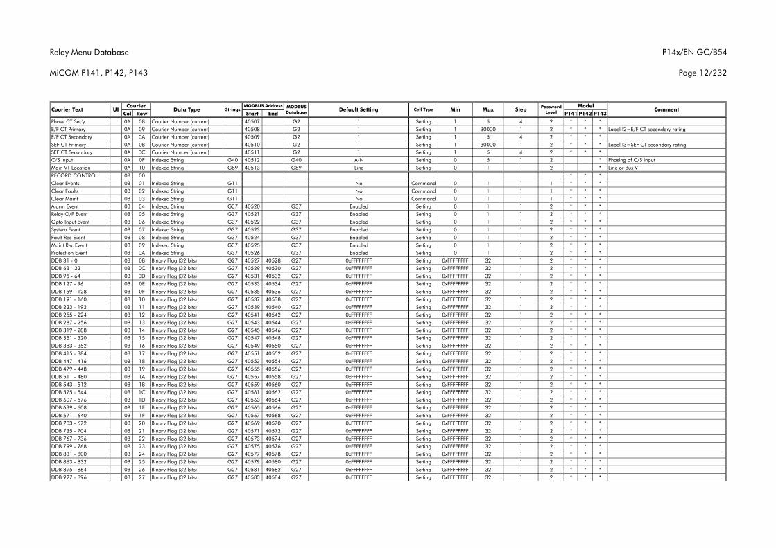
Relay Menu Database
MiCOM P141, P142, P143
P14x/EN GC/B54
Page 12/232
Col Row Start End P141 P142 P143Courier Text UI Data Type Strings
CourierCommentMODBUS
Database Default Setting Cell Type MinMODBUS Address Model
Max Step Password Level
Phase CT Sec'y 0A 08 Courier Number (current) 40507 G2 1 Setting 1 5 4 2 * * *E/F CT Primary 0A 09 Courier Number (current) 40508 G2 1 Setting 1 30000 1 2 * * * Label I2=E/F CT secondary ratingE/F CT Secondary 0A 0A Courier Number (current) 40509 G2 1 Setting 1 5 4 2 * * *SEF CT Primary 0A 0B Courier Number (current) 40510 G2 1 Setting 1 30000 1 2 * * * Label I3=SEF CT secondary ratingSEF CT Secondary 0A 0C Courier Number (current) 40511 G2 1 Setting 1 5 4 2 * * *C/S Input 0A 0F Indexed String G40 40512 G40 A-N Setting 0 5 1 2 * Phasing of C/S inputMain VT Location 0A 10 Indexed String G89 40513 G89 Line Setting 0 1 1 2 * Line or Bus VTRECORD CONTROL 0B 00 * * *Clear Events 0B 01 Indexed String G11 No Command 0 1 1 1 * * *Clear Faults 0B 02 Indexed String G11 No Command 0 1 1 1 * * *Clear Maint 0B 03 Indexed String G11 No Command 0 1 1 1 * * *Alarm Event 0B 04 Indexed String G37 40520 G37 Enabled Setting 0 1 1 2 * * *Relay O/P Event 0B 05 Indexed String G37 40521 G37 Enabled Setting 0 1 1 2 * * *Opto Input Event 0B 06 Indexed String G37 40522 G37 Enabled Setting 0 1 1 2 * * *System Event 0B 07 Indexed String G37 40523 G37 Enabled Setting 0 1 1 2 * * *Fault Rec Event 0B 08 Indexed String G37 40524 G37 Enabled Setting 0 1 1 2 * * *Maint Rec Event 0B 09 Indexed String G37 40525 G37 Enabled Setting 0 1 1 2 * * *Protection Event 0B 0A Indexed String G37 40526 G37 Enabled Setting 0 1 1 2 * * *DDB 31 - 0 0B 0B Binary Flag (32 bits) G27 40527 40528 G27 0xFFFFFFFF Setting 0xFFFFFFFF 32 1 2 * * *DDB 63 - 32 0B 0C Binary Flag (32 bits) G27 40529 40530 G27 0xFFFFFFFF Setting 0xFFFFFFFF 32 1 2 * * *DDB 95 - 64 0B 0D Binary Flag (32 bits) G27 40531 40532 G27 0xFFFFFFFF Setting 0xFFFFFFFF 32 1 2 * * *DDB 127 - 96 0B 0E Binary Flag (32 bits) G27 40533 40534 G27 0xFFFFFFFF Setting 0xFFFFFFFF 32 1 2 * * *DDB 159 - 128 0B 0F Binary Flag (32 bits) G27 40535 40536 G27 0xFFFFFFFF Setting 0xFFFFFFFF 32 1 2 * * *DDB 191 - 160 0B 10 Binary Flag (32 bits) G27 40537 40538 G27 0xFFFFFFFF Setting 0xFFFFFFFF 32 1 2 * * *DDB 223 - 192 0B 11 Binary Flag (32 bits) G27 40539 40540 G27 0xFFFFFFFF Setting 0xFFFFFFFF 32 1 2 * * *DDB 255 - 224 0B 12 Binary Flag (32 bits) G27 40541 40542 G27 0xFFFFFFFF Setting 0xFFFFFFFF 32 1 2 * * *DDB 287 - 256 0B 13 Binary Flag (32 bits) G27 40543 40544 G27 0xFFFFFFFF Setting 0xFFFFFFFF 32 1 2 * * *DDB 319 - 288 0B 14 Binary Flag (32 bits) G27 40545 40546 G27 0xFFFFFFFF Setting 0xFFFFFFFF 32 1 2 * * *DDB 351 - 320 0B 15 Binary Flag (32 bits) G27 40547 40548 G27 0xFFFFFFFF Setting 0xFFFFFFFF 32 1 2 * * *DDB 383 - 352 0B 16 Binary Flag (32 bits) G27 40549 40550 G27 0xFFFFFFFF Setting 0xFFFFFFFF 32 1 2 * * *DDB 415 - 384 0B 17 Binary Flag (32 bits) G27 40551 40552 G27 0xFFFFFFFF Setting 0xFFFFFFFF 32 1 2 * * *DDB 447 - 416 0B 18 Binary Flag (32 bits) G27 40553 40554 G27 0xFFFFFFFF Setting 0xFFFFFFFF 32 1 2 * * *DDB 479 - 448 0B 19 Binary Flag (32 bits) G27 40555 40556 G27 0xFFFFFFFF Setting 0xFFFFFFFF 32 1 2 * * *DDB 511 - 480 0B 1A Binary Flag (32 bits) G27 40557 40558 G27 0xFFFFFFFF Setting 0xFFFFFFFF 32 1 2 * * *DDB 543 - 512 0B 1B Binary Flag (32 bits) G27 40559 40560 G27 0xFFFFFFFF Setting 0xFFFFFFFF 32 1 2 * * *DDB 575 - 544 0B 1C Binary Flag (32 bits) G27 40561 40562 G27 0xFFFFFFFF Setting 0xFFFFFFFF 32 1 2 * * *DDB 607 - 576 0B 1D Binary Flag (32 bits) G27 40563 40564 G27 0xFFFFFFFF Setting 0xFFFFFFFF 32 1 2 * * *DDB 639 - 608 0B 1E Binary Flag (32 bits) G27 40565 40566 G27 0xFFFFFFFF Setting 0xFFFFFFFF 32 1 2 * * *DDB 671 - 640 0B 1F Binary Flag (32 bits) G27 40567 40568 G27 0xFFFFFFFF Setting 0xFFFFFFFF 32 1 2 * * *DDB 703 - 672 0B 20 Binary Flag (32 bits) G27 40569 40570 G27 0xFFFFFFFF Setting 0xFFFFFFFF 32 1 2 * * *DDB 735 - 704 0B 21 Binary Flag (32 bits) G27 40571 40572 G27 0xFFFFFFFF Setting 0xFFFFFFFF 32 1 2 * * *DDB 767 - 736 0B 22 Binary Flag (32 bits) G27 40573 40574 G27 0xFFFFFFFF Setting 0xFFFFFFFF 32 1 2 * * *DDB 799 - 768 0B 23 Binary Flag (32 bits) G27 40575 40576 G27 0xFFFFFFFF Setting 0xFFFFFFFF 32 1 2 * * *DDB 831 - 800 0B 24 Binary Flag (32 bits) G27 40577 40578 G27 0xFFFFFFFF Setting 0xFFFFFFFF 32 1 2 * * *DDB 863 - 832 0B 25 Binary Flag (32 bits) G27 40579 40580 G27 0xFFFFFFFF Setting 0xFFFFFFFF 32 1 2 * * *DDB 895 - 864 0B 26 Binary Flag (32 bits) G27 40581 40582 G27 0xFFFFFFFF Setting 0xFFFFFFFF 32 1 2 * * *DDB 927 - 896 0B 27 Binary Flag (32 bits) G27 40583 40584 G27 0xFFFFFFFF Setting 0xFFFFFFFF 32 1 2 * * *
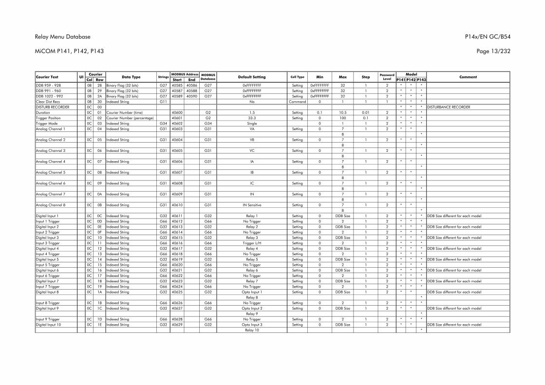
Relay Menu Database
MiCOM P141, P142, P143
P14x/EN GC/B54
Page 13/232
Col Row Start End P141 P142 P143Courier Text UI Data Type Strings
CourierCommentMODBUS
Database Default Setting Cell Type MinMODBUS Address Model
Max Step Password Level
DDB 959 - 928 0B 28 Binary Flag (32 bits) G27 40585 40586 G27 0xFFFFFFFF Setting 0xFFFFFFFF 32 1 2 * * *DDB 991 - 960 0B 29 Binary Flag (32 bits) G27 40587 40588 G27 0xFFFFFFFF Setting 0xFFFFFFFF 32 1 2 * * *DDB 1022 - 992 0B 2A Binary Flag (32 bits) G27 40589 40590 G27 0xFFFFFFFF Setting 0xFFFFFFFF 32 1 2 * * *Clear Dist Recs 0B 30 Indexed String G11 No Command 0 1 1 1 * * *DISTURB RECORDER 0C 00 * * * DISTURBANCE RECORDERDuration 0C 01 Courier Number (time) 40600 G2 1.5 Setting 0.1 10.5 0.01 2 * * *Trigger Position 0C 02 Courier Number (percentage) 40601 G2 33.3 Setting 0 100 0.1 2 * * *Trigger Mode 0C 03 Indexed String G34 40602 G34 Single 0 1 1 2 * * *Analog Channel 1 0C 04 Indexed String G31 40603 G31 VA Setting 0 7 1 2 * *
8 *Analog Channel 2 0C 05 Indexed String G31 40604 G31 VB Setting 0 7 1 2 * *
8 *Analog Channel 3 0C 06 Indexed String G31 40605 G31 VC Setting 0 7 1 2 * *
8 *Analog Channel 4 0C 07 Indexed String G31 40606 G31 IA Setting 0 7 1 2 * *
8 *Analog Channel 5 0C 08 Indexed String G31 40607 G31 IB Setting 0 7 1 2 * *
8 *Analog Channel 6 0C 09 Indexed String G31 40608 G31 IC Setting 0 7 1 2 * *
8 *Analog Channel 7 0C 0A Indexed String G31 40609 G31 IN Setting 0 7 1 2 * *
8 *Analog Channel 8 0C 0B Indexed String G31 40610 G31 IN Sensitive Setting 0 7 1 2 * *
8 *Digital Input 1 0C 0C Indexed String G32 40611 G32 Relay 1 Setting 0 DDB Size 1 2 * * * DDB Size different for each modelInput 1 Trigger 0C 0D Indexed String G66 40612 G66 No Trigger Setting 0 2 1 2 * * *Digital Input 2 0C 0E Indexed String G32 40613 G32 Relay 2 Setting 0 DDB Size 1 2 * * * DDB Size different for each modelInput 2 Trigger 0C 0F Indexed String G66 40614 G66 No Trigger Setting 0 2 1 2 * * *Digital Input 3 0C 10 Indexed String G32 40615 G32 Relay 3 Setting 0 DDB Size 1 2 * * * DDB Size different for each modelInput 3 Trigger 0C 11 Indexed String G66 40616 G66 Trigger L/H Setting 0 2 1 2 * * *Digital Input 4 0C 12 Indexed String G32 40617 G32 Relay 4 Setting 0 DDB Size 1 2 * * * DDB Size different for each modelInput 4 Trigger 0C 13 Indexed String G66 40618 G66 No Trigger Setting 0 2 1 2 * * *Digital Input 5 0C 14 Indexed String G32 40619 G32 Relay 5 Setting 0 DDB Size 1 2 * * * DDB Size different for each modelInput 5 Trigger 0C 15 Indexed String G66 40620 G66 No Trigger Setting 0 2 1 2 * * *Digital Input 6 0C 16 Indexed String G32 40621 G32 Relay 6 Setting 0 DDB Size 1 2 * * * DDB Size different for each modelInput 6 Trigger 0C 17 Indexed String G66 40622 G66 No Trigger Setting 0 2 1 2 * * *Digital Input 7 0C 18 Indexed String G32 40623 G32 Relay 7 Setting 0 DDB Size 1 2 * * * DDB Size different for each modelInput 7 Trigger 0C 19 Indexed String G66 40624 G66 No Trigger Setting 0 2 1 2 * * *Digital Input 8 0C 1A Indexed String G32 40625 G32 Opto Input 1 Setting 0 DDB Size 1 2 * * DDB Size different for each model
Relay 8 *Input 8 Trigger 0C 1B Indexed String G66 40626 G66 No Trigger Setting 0 2 1 2 * * *Digital Input 9 0C 1C Indexed String G32 40627 G32 Opto Input 2 Setting 0 DDB Size 1 2 * * DDB Size different for each model
Relay 9 *Input 9 Trigger 0C 1D Indexed String G66 40628 G66 No Trigger Setting 0 2 1 2 * * *Digital Input 10 0C 1E Indexed String G32 40629 G32 Opto Input 3 Setting 0 DDB Size 1 2 * * DDB Size different for each model
Relay 10 *
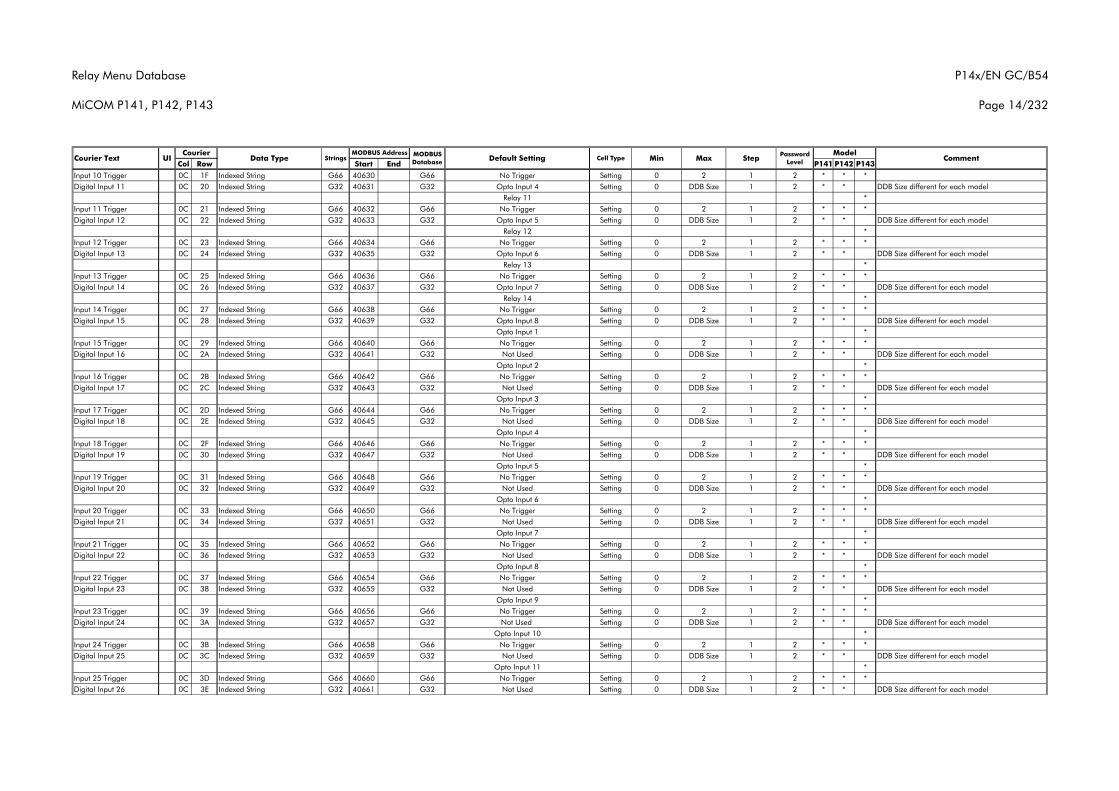
Relay Menu Database
MiCOM P141, P142, P143
P14x/EN GC/B54
Page 14/232
Col Row Start End P141 P142 P143Courier Text UI Data Type Strings
CourierCommentMODBUS
Database Default Setting Cell Type MinMODBUS Address Model
Max Step Password Level
Input 10 Trigger 0C 1F Indexed String G66 40630 G66 No Trigger Setting 0 2 1 2 * * *Digital Input 11 0C 20 Indexed String G32 40631 G32 Opto Input 4 Setting 0 DDB Size 1 2 * * DDB Size different for each model
Relay 11 *Input 11 Trigger 0C 21 Indexed String G66 40632 G66 No Trigger Setting 0 2 1 2 * * *Digital Input 12 0C 22 Indexed String G32 40633 G32 Opto Input 5 Setting 0 DDB Size 1 2 * * DDB Size different for each model
Relay 12 *Input 12 Trigger 0C 23 Indexed String G66 40634 G66 No Trigger Setting 0 2 1 2 * * *Digital Input 13 0C 24 Indexed String G32 40635 G32 Opto Input 6 Setting 0 DDB Size 1 2 * * DDB Size different for each model
Relay 13 *Input 13 Trigger 0C 25 Indexed String G66 40636 G66 No Trigger Setting 0 2 1 2 * * *Digital Input 14 0C 26 Indexed String G32 40637 G32 Opto Input 7 Setting 0 DDB Size 1 2 * * DDB Size different for each model
Relay 14 *Input 14 Trigger 0C 27 Indexed String G66 40638 G66 No Trigger Setting 0 2 1 2 * * *Digital Input 15 0C 28 Indexed String G32 40639 G32 Opto Input 8 Setting 0 DDB Size 1 2 * * DDB Size different for each model
Opto Input 1 *Input 15 Trigger 0C 29 Indexed String G66 40640 G66 No Trigger Setting 0 2 1 2 * * *Digital Input 16 0C 2A Indexed String G32 40641 G32 Not Used Setting 0 DDB Size 1 2 * * DDB Size different for each model
Opto Input 2 *Input 16 Trigger 0C 2B Indexed String G66 40642 G66 No Trigger Setting 0 2 1 2 * * *Digital Input 17 0C 2C Indexed String G32 40643 G32 Not Used Setting 0 DDB Size 1 2 * * DDB Size different for each model
Opto Input 3 *Input 17 Trigger 0C 2D Indexed String G66 40644 G66 No Trigger Setting 0 2 1 2 * * *Digital Input 18 0C 2E Indexed String G32 40645 G32 Not Used Setting 0 DDB Size 1 2 * * DDB Size different for each model
Opto Input 4 *Input 18 Trigger 0C 2F Indexed String G66 40646 G66 No Trigger Setting 0 2 1 2 * * *Digital Input 19 0C 30 Indexed String G32 40647 G32 Not Used Setting 0 DDB Size 1 2 * * DDB Size different for each model
Opto Input 5 *Input 19 Trigger 0C 31 Indexed String G66 40648 G66 No Trigger Setting 0 2 1 2 * * *Digital Input 20 0C 32 Indexed String G32 40649 G32 Not Used Setting 0 DDB Size 1 2 * * DDB Size different for each model
Opto Input 6 *Input 20 Trigger 0C 33 Indexed String G66 40650 G66 No Trigger Setting 0 2 1 2 * * *Digital Input 21 0C 34 Indexed String G32 40651 G32 Not Used Setting 0 DDB Size 1 2 * * DDB Size different for each model
Opto Input 7 *Input 21 Trigger 0C 35 Indexed String G66 40652 G66 No Trigger Setting 0 2 1 2 * * *Digital Input 22 0C 36 Indexed String G32 40653 G32 Not Used Setting 0 DDB Size 1 2 * * DDB Size different for each model
Opto Input 8 *Input 22 Trigger 0C 37 Indexed String G66 40654 G66 No Trigger Setting 0 2 1 2 * * *Digital Input 23 0C 38 Indexed String G32 40655 G32 Not Used Setting 0 DDB Size 1 2 * * DDB Size different for each model
Opto Input 9 *Input 23 Trigger 0C 39 Indexed String G66 40656 G66 No Trigger Setting 0 2 1 2 * * *Digital Input 24 0C 3A Indexed String G32 40657 G32 Not Used Setting 0 DDB Size 1 2 * * DDB Size different for each model
Opto Input 10 *Input 24 Trigger 0C 3B Indexed String G66 40658 G66 No Trigger Setting 0 2 1 2 * * *Digital Input 25 0C 3C Indexed String G32 40659 G32 Not Used Setting 0 DDB Size 1 2 * * DDB Size different for each model
Opto Input 11 *Input 25 Trigger 0C 3D Indexed String G66 40660 G66 No Trigger Setting 0 2 1 2 * * *Digital Input 26 0C 3E Indexed String G32 40661 G32 Not Used Setting 0 DDB Size 1 2 * * DDB Size different for each model
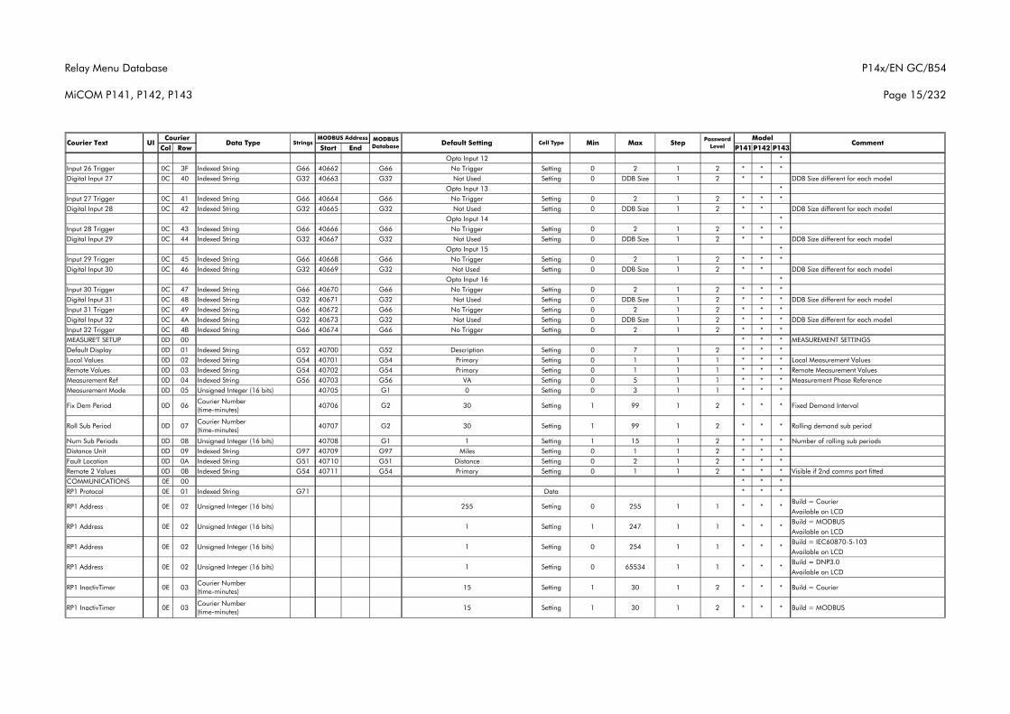
Relay Menu Database
MiCOM P141, P142, P143
P14x/EN GC/B54
Page 15/232
Col Row Start End P141 P142 P143Courier Text UI Data Type Strings
CourierCommentMODBUS
Database Default Setting Cell Type MinMODBUS Address Model
Max Step Password Level
Opto Input 12 *Input 26 Trigger 0C 3F Indexed String G66 40662 G66 No Trigger Setting 0 2 1 2 * * *Digital Input 27 0C 40 Indexed String G32 40663 G32 Not Used Setting 0 DDB Size 1 2 * * DDB Size different for each model
Opto Input 13 *Input 27 Trigger 0C 41 Indexed String G66 40664 G66 No Trigger Setting 0 2 1 2 * * *Digital Input 28 0C 42 Indexed String G32 40665 G32 Not Used Setting 0 DDB Size 1 2 * * DDB Size different for each model
Opto Input 14 *Input 28 Trigger 0C 43 Indexed String G66 40666 G66 No Trigger Setting 0 2 1 2 * * *Digital Input 29 0C 44 Indexed String G32 40667 G32 Not Used Setting 0 DDB Size 1 2 * * DDB Size different for each model
Opto Input 15 *Input 29 Trigger 0C 45 Indexed String G66 40668 G66 No Trigger Setting 0 2 1 2 * * *Digital Input 30 0C 46 Indexed String G32 40669 G32 Not Used Setting 0 DDB Size 1 2 * * DDB Size different for each model
Opto Input 16 *Input 30 Trigger 0C 47 Indexed String G66 40670 G66 No Trigger Setting 0 2 1 2 * * *Digital Input 31 0C 48 Indexed String G32 40671 G32 Not Used Setting 0 DDB Size 1 2 * * * DDB Size different for each modelInput 31 Trigger 0C 49 Indexed String G66 40672 G66 No Trigger Setting 0 2 1 2 * * *Digital Input 32 0C 4A Indexed String G32 40673 G32 Not Used Setting 0 DDB Size 1 2 * * * DDB Size different for each modelInput 32 Trigger 0C 4B Indexed String G66 40674 G66 No Trigger Setting 0 2 1 2 * * *MEASURE'T SETUP 0D 00 * * * MEASUREMENT SETTINGSDefault Display 0D 01 Indexed String G52 40700 G52 Description Setting 0 7 1 2 * * *Local Values 0D 02 Indexed String G54 40701 G54 Primary Setting 0 1 1 1 * * * Local Measurement ValuesRemote Values 0D 03 Indexed String G54 40702 G54 Primary Setting 0 1 1 1 * * * Remote Measurement ValuesMeasurement Ref 0D 04 Indexed String G56 40703 G56 VA Setting 0 5 1 1 * * * Measurement Phase ReferenceMeasurement Mode 0D 05 Unsigned Integer (16 bits) 40705 G1 0 Setting 0 3 1 1 * * *
Fix Dem Period 0D 06Courier Number (time-minutes)
40706 G2 30 Setting 1 99 1 2 * * * Fixed Demand Interval
Roll Sub Period 0D 07Courier Number (time-minutes)
40707 G2 30 Setting 1 99 1 2 * * * Rolling demand sub period
Num Sub Periods 0D 08 Unsigned Integer (16 bits) 40708 G1 1 Setting 1 15 1 2 * * * Number of rolling sub periodsDistance Unit 0D 09 Indexed String G97 40709 G97 Miles Setting 0 1 1 2 * * *Fault Location 0D 0A Indexed String G51 40710 G51 Distance Setting 0 2 1 2 * * *Remote 2 Values 0D 0B Indexed String G54 40711 G54 Primary Setting 0 1 1 2 * * * Visible if 2nd comms port fittedCOMMUNICATIONS 0E 00 * * *RP1 Protocol 0E 01 Indexed String G71 Data * * *
Build = CourierAvailable on LCDBuild = MODBUSAvailable on LCDBuild = IEC60870-5-103Available on LCDBuild = DNP3.0Available on LCD
RP1 InactivTimer 0E 03Courier Number (time-minutes)
15 Setting 1 30 1 2 * * * Build = Courier
RP1 InactivTimer 0E 03Courier Number (time-minutes)
15 Setting 1 30 1 2 * * * Build = MODBUS
1 * *255 Setting 0 1RP1 Address 0E 02 Unsigned Integer (16 bits)
*
*0E 02 1 Setting 1 1 1 *247
2540
Unsigned Integer (16 bits)
Unsigned Integer (16 bits)
RP1 Address *
1 1 * *
*255
RP1 Address 0E 02 1 Setting
RP1 Address 0E 02 Unsigned Integer (16 bits) 0 65534 11 Setting 1 * * *
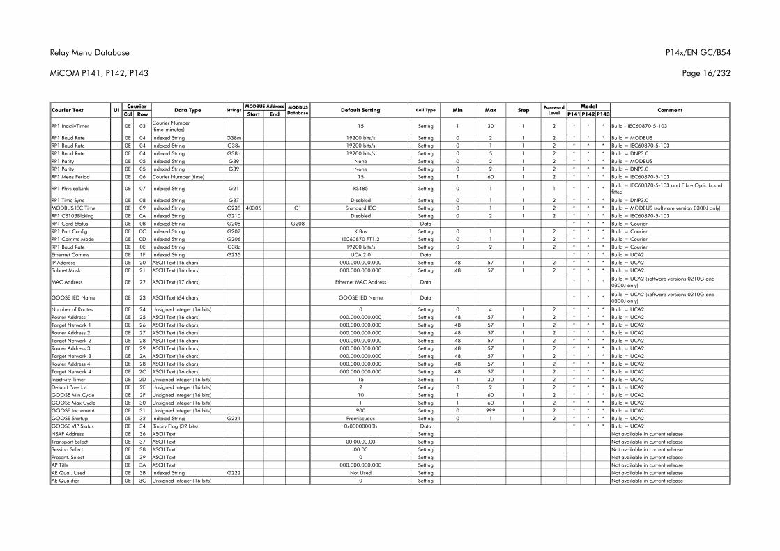
Relay Menu Database
MiCOM P141, P142, P143
P14x/EN GC/B54
Page 16/232
Col Row Start End P141 P142 P143Courier Text UI Data Type Strings
CourierCommentMODBUS
Database Default Setting Cell Type MinMODBUS Address Model
Max Step Password Level
RP1 InactivTimer 0E 03Courier Number (time-minutes)
15 Setting 1 30 1 2 * * * Build - IEC60870-5-103
RP1 Baud Rate 0E 04 Indexed String G38m 19200 bits/s Setting 0 2 1 2 * * * Build = MODBUSRP1 Baud Rate 0E 04 Indexed String G38v 19200 bits/s Setting 0 1 1 2 * * * Build = IEC60870-5-103RP1 Baud Rate 0E 04 Indexed String G38d 19200 bits/s Setting 0 5 1 2 * * * Build = DNP3.0RP1 Parity 0E 05 Indexed String G39 None Setting 0 2 1 2 * * * Build = MODBUSRP1 Parity 0E 05 Indexed String G39 None Setting 0 2 1 2 * * * Build = DNP3.0RP1 Meas Period 0E 06 Courier Number (time) 15 Setting 1 60 1 2 * * * Build = IEC60870-5-103
RP1 PhysicalLink 0E 07 Indexed String G21 RS485 Setting 0 1 1 1 * * *Build = IEC60870-5-103 and Fibre Optic board fitted
RP1 Time Sync 0E 08 Indexed String G37 Disabled Setting 0 1 1 2 * * * Build = DNP3.0MODBUS IEC Time 0E 09 Indexed String G238 40306 G1 Standard IEC Setting 0 1 1 2 * * * Build = MODBUS (software version 0300J only)RP1 CS103Blcking 0E 0A Indexed String G210 Disabled Setting 0 2 1 2 * * * Build = IEC60870-5-103RP1 Card Status 0E 0B Indexed String G208 G208 Data * * * Build = CourierRP1 Port Config 0E 0C Indexed String G207 K Bus Setting 0 1 1 2 * * * Build = CourierRP1 Comms Mode 0E 0D Indexed String G206 IEC60870 FT1.2 Setting 0 1 1 2 * * * Build = CourierRP1 Baud Rate 0E 0E Indexed String G38c 19200 bits/s Setting 0 2 1 2 * * * Build = CourierEthernet Comms 0E 1F Indexed String G235 UCA 2.0 Data * * * Build = UCA2IP Address 0E 20 ASCII Text (16 chars) 000.000.000.000 Setting 48 57 1 2 * * * Build = UCA2Subnet Mask 0E 21 ASCII Text (16 chars) 000.000.000.000 Setting 48 57 1 2 * * * Build = UCA2
MAC Address 0E 22 ASCII Text (17 chars) Ethernet MAC Address Data * * *Build = UCA2 (software versions 0210G and 0300J only)
GOOSE IED Name 0E 23 ASCII Text (64 chars) GOOSE IED Name Data * * *Build = UCA2 (software versions 0210G and 0300J only)
Number of Routes 0E 24 Unsigned Integer (16 bits) 0 Setting 0 4 1 2 * * * Build = UCA2Router Address 1 0E 25 ASCII Text (16 chars) 000.000.000.000 Setting 48 57 1 2 * * * Build = UCA2Target Network 1 0E 26 ASCII Text (16 chars) 000.000.000.000 Setting 48 57 1 2 * * * Build = UCA2Router Address 2 0E 27 ASCII Text (16 chars) 000.000.000.000 Setting 48 57 1 2 * * * Build = UCA2Target Network 2 0E 28 ASCII Text (16 chars) 000.000.000.000 Setting 48 57 1 2 * * * Build = UCA2Router Address 3 0E 29 ASCII Text (16 chars) 000.000.000.000 Setting 48 57 1 2 * * * Build = UCA2Target Network 3 0E 2A ASCII Text (16 chars) 000.000.000.000 Setting 48 57 1 2 * * * Build = UCA2Router Address 4 0E 2B ASCII Text (16 chars) 000.000.000.000 Setting 48 57 1 2 * * * Build = UCA2Target Network 4 0E 2C ASCII Text (16 chars) 000.000.000.000 Setting 48 57 1 2 * * * Build = UCA2Inactivity Timer 0E 2D Unsigned Integer (16 bits) 15 Setting 1 30 1 2 * * * Build = UCA2Default Pass Lvl 0E 2E Unsigned Integer (16 bits) 2 Setting 0 2 1 2 * * * Build = UCA2GOOSE Min Cycle 0E 2F Unsigned Integer (16 bits) 10 Setting 1 60 1 2 * * * Build = UCA2GOOSE Max Cycle 0E 30 Unsigned Integer (16 bits) 1 Setting 1 60 1 2 * * * Build = UCA2GOOSE Increment 0E 31 Unsigned Integer (16 bits) 900 Setting 0 999 1 2 * * * Build = UCA2GOOSE Startup 0E 32 Indexed String G221 Promiscuous Setting 0 1 1 2 * * * Build = UCA2GOOSE VIP Status 0E 34 Binary Flag (32 bits) 0x00000000h Data * * * Build = UCA2NSAP Address 0E 36 ASCII Text Setting Not available in current releaseTransport Select 0E 37 ASCII Text 00.00.00.00 Setting Not available in current releaseSession Select 0E 38 ASCII Text 00.00 Setting Not available in current releasePresent. Select 0E 39 ASCII Text 0 Setting Not available in current releaseAP Title 0E 3A ASCII Text 000.000.000.000 Setting Not available in current releaseAE Qual. Used 0E 3B Indexed String G222 Not Used Setting Not available in current releaseAE Qualifier 0E 3C Unsigned Integer (16 bits) 0 Setting Not available in current release
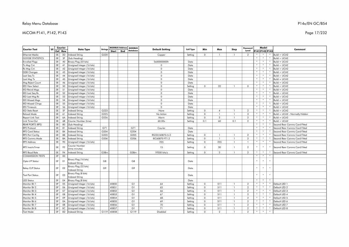
Relay Menu Database
MiCOM P141, P142, P143
P14x/EN GC/B54
Page 17/232
Col Row Start End P141 P142 P143Courier Text UI Data Type Strings
CourierCommentMODBUS
Database Default Setting Cell Type MinMODBUS Address Model
Max Step Password Level
Ethernet Media 0E 3D Indexed String G220 Copper Setting 0 1 1 2 * * * Build = UCA2GOOSE STATISTICS 0E 3F (Sub Heading) * * * Build = UCA2Enrolled Flags 0E 40 Binary Flag (32 bits) 0x00000000h Data * * * Build = UCA2Tx Msg Cnt. 0E 41 Unsigned Integer (16 bits) 0 Data * * * Build = UCA2Rx Msg Cnt. 0E 42 Unsigned Integer (16 bits) 0 Data * * * Build = UCA2DDB Changes 0E 43 Unsigned Integer (16 bits) 0 Data * * * Build = UCA2Last Seq Tx 0E 44 Unsigned Integer (16 bits) 0 Data * * * Build = UCA2Last Msg Tx 0E 45 Unsigned Integer (16 bits) 0 Data * * * Build = UCA2Msg Reject Count 0E 46 Unsigned Integer (16 bits) 0 Data * * * Build = UCA2IED View Select 0E 50 Unsigned Integer (16 bits) 0 Setting 0 32 1 0 * * * Build = UCA2IED Recvd Msgs 0E 51 Unsigned Integer (16 bits) 0 Data * * * Build = UCA2IED Last Seq Rx 0E 52 Unsigned Integer (16 bits) 0 Data * * * Build = UCA2IED Last Msg Rx 0E 53 Unsigned Integer (16 bits) 0 Data * * * Build = UCA2IED Missed Msgs 0E 54 Unsigned Integer (16 bits) 0 Data * * * Build = UCA2IED Missed Chngs 0E 55 Unsigned Integer (16 bits) 0 Data * * * Build = UCA2IED Timeouts 0E 56 Unsigned Integer (16 bits) 0 Data * * * Build = UCA2IED Stats Reset 0E 5F Indexed String G223 None Setting 0 4 1 2 * * * Build = UCA2Reload Mode 0E 61 Indexed String G225 No Action Setting 0 1 1 3 * * * Build = UCA2 - Normally HiddenReport Link Test 0E 6A Indexed String G226 Alarm Setting 0 2 1 2 * * * Build = UCA2Link Time-Out 0E 6B Courier Number (time) 60.00s Setting 0.1 60 0.1 2 * * * Build = UCA2REAR PORT2 (RP2) 0E 80 (Sub Heading) * * * Second Rear Comms Card FittedRP2 Protocol 0E 81 Indexed String G71 G71 Courier Data * * * Second Rear Comms Card FittedRP2 Card Status 0E 84 Indexed String G204 G204 Data * * * Second Rear Comms Card FittedRP2 Port Config 0E 88 Indexed String G205 G205 RS232/60870-5-2 Setting 0 1 1 2 * * * Second Rear Comms Card FittedRP2 Comms Mode 0E 8A Indexed String G206 G206 IEC60870 FT1.2 Setting 0 1 1 2 * * * Second Rear Comms Card FittedRP2 Address 0E 90 Unsigned Integer (16 bits) 255 Setting 0 255 1 1 * * * Second Rear Comms Card Fitted
RP2 InactivTimer 0E 92Courier Number (time-minutes)
15 Setting 0 30 1 2 * * * Second Rear Comms Card Fitted
RP2 Baud Rate 0E 94 Indexed String G38m G38m 19200 bits/s Setting 0 2 1 2 * * * Second Rear Comms Card FittedCOMMISSION TESTS 0F 00 * * *
Binary Flag (16 bits)Indexed StringBinary Flag (32 bits)Indexed StringBinary Flag (8 bits)Indexed String
LED Status 0F 04 Binary Flag (8 bits) Data * * *Monitor Bit 1 0F 05 Unsigned Integer (16 bits) 40850 G1 64 Setting 0 511 1 2 * * * Default LED 1Monitor Bit 2 0F 06 Unsigned Integer (16 bits) 40851 G1 65 Setting 0 511 1 2 * * * Default LED 2Monitor Bit 3 0F 07 Unsigned Integer (16 bits) 40852 G1 66 Setting 0 511 1 2 * * * Default LED 3Monitor Bit 4 0F 08 Unsigned Integer (16 bits) 40853 G1 67 Setting 0 511 1 2 * * * Default LED 4Monitor Bit 5 0F 09 Unsigned Integer (16 bits) 40854 G1 68 Setting 0 511 1 2 * * * Default LED 5Monitor Bit 6 0F 0A Unsigned Integer (16 bits) 40855 G1 69 Setting 0 511 1 2 * * * Default LED 6Monitor Bit 7 0F 0B Unsigned Integer (16 bits) 40856 G1 70 Setting 0 511 1 2 * * * Default LED 7Monitor Bit 8 0F 0C Unsigned Integer (16 bits) 40857 G1 71 Setting 0 511 1 2 * * * Default LED 8Test Mode 0F 0D Indexed String G119 40858 G119 Disabled Setting 0 2 1 2 * * *
Test Port Status 0F 03
* * *G9Relay O/P Status 0F 02
Data * * *Opto I/P Status 0F 01 G8 G8
Data
G9 Data
* * *
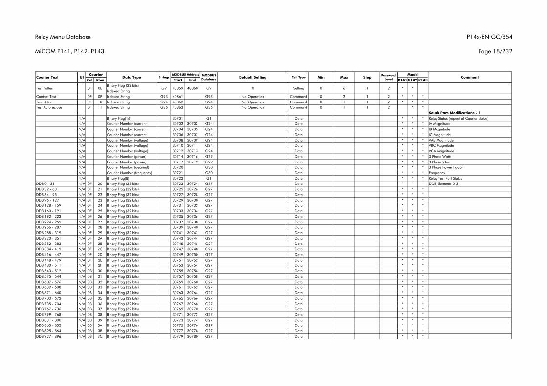
Relay Menu Database
MiCOM P141, P142, P143
P14x/EN GC/B54
Page 18/232
Col Row Start End P141 P142 P143Courier Text UI Data Type Strings
CourierCommentMODBUS
Database Default Setting Cell Type MinMODBUS Address Model
Max Step Password Level
Binary Flag (32 bits)Indexed String
Contact Test 0F 0F Indexed String G93 40861 G93 No Operation Command 0 2 1 2 * * *Test LEDs 0F 10 Indexed String G94 40862 G94 No Operation Command 0 1 1 2 * * *Test Autoreclose 0F 11 Indexed String G36 40863 G36 No Operation Command 0 1 1 2 * *
South Pars Modifications - 1N/A Binary Flag(16) 30701 G1 Data * * * Relay Status (repeat of Courier status)N/A Courier Number (current) 30702 30703 G24 Data * * * IA MagnitudeN/A Courier Number (current) 30704 30705 G24 Data * * * IB MagnitudeN/A Courier Number (current) 30706 30707 G24 Data * * * IC MagnitudeN/A Courier Number (voltage) 30708 30709 G24 Data * * * VAB MagnitudeN/A Courier Number (voltage) 30710 30711 G24 Data * * * VBC MagnitudeN/A Courier Number (voltage) 30712 30713 G24 Data * * * VCA MagnitudeN/A Courier Number (power) 30714 30716 G29 Data * * * 3 Phase WattsN/A Courier Number (power) 30717 30719 G29 Data * * * 3 Phase VArsN/A Courier Number (decimal) 30720 G30 Data * * * 3 Phase Power FactorN/A Courier Number (frequency) 30721 G30 Data * * * FrequencyN/A Binary Flag(8) 30722 G1 Data * * * Relay Test Port Status
DDB 0 - 31 N/A 0F 20 Binary Flag (32 bits) 30723 30724 G27 Data * * * DDB Elements 0-31DDB 32 - 63 N/A 0F 21 Binary Flag (32 bits) 30725 30726 G27 Data * * *DDB 64 - 95 N/A 0F 22 Binary Flag (32 bits) 30727 30728 G27 Data * * *DDB 96 - 127 N/A 0F 23 Binary Flag (32 bits) 30729 30730 G27 Data * * *DDB 128 - 159 N/A 0F 24 Binary Flag (32 bits) 30731 30732 G27 Data * * *DDB 160 - 191 N/A 0F 25 Binary Flag (32 bits) 30733 30734 G27 Data * * *DDB 192 - 223 N/A 0F 26 Binary Flag (32 bits) 30735 30736 G27 Data * * *DDB 224 - 255 N/A 0F 27 Binary Flag (32 bits) 30737 30738 G27 Data * * *DDB 256 - 287 N/A 0F 28 Binary Flag (32 bits) 30739 30740 G27 Data * * *DDB 288 - 319 N/A 0F 29 Binary Flag (32 bits) 30741 30742 G27 Data * * *DDB 320 - 351 N/A 0F 2A Binary Flag (32 bits) 30743 30744 G27 Data * * *DDB 352 - 383 N/A 0F 2B Binary Flag (32 bits) 30745 30746 G27 Data * * *DDB 384 - 415 N/A 0F 2C Binary Flag (32 bits) 30747 30748 G27 Data * * *DDB 416 - 447 N/A 0F 2D Binary Flag (32 bits) 30749 30750 G27 Data * * *DDB 448 - 479 N/A 0F 2E Binary Flag (32 bits) 30751 30752 G27 Data * * *DDB 480 - 511 N/A 0F 2F Binary Flag (32 bits) 30753 30754 G27 Data * * *DDB 543 - 512 N/A 0B 30 Binary Flag (32 bits) 30755 30756 G27 Data * * *DDB 575 - 544 N/A 0B 31 Binary Flag (32 bits) 30757 30758 G27 Data * * *DDB 607 - 576 N/A 0B 32 Binary Flag (32 bits) 30759 30760 G27 Data * * *DDB 639 - 608 N/A 0B 33 Binary Flag (32 bits) 30761 30762 G27 Data * * *DDB 671 - 640 N/A 0B 34 Binary Flag (32 bits) 30763 30764 G27 Data * * *DDB 703 - 672 N/A 0B 35 Binary Flag (32 bits) 30765 30766 G27 Data * * *DDB 735 - 704 N/A 0B 36 Binary Flag (32 bits) 30767 30768 G27 Data * * *DDB 767 - 736 N/A 0B 37 Binary Flag (32 bits) 30769 30770 G27 Data * * *DDB 799 - 768 N/A 0B 38 Binary Flag (32 bits) 30771 30772 G27 Data * * *DDB 831 - 800 N/A 0B 39 Binary Flag (32 bits) 30773 30774 G27 Data * * *DDB 863 - 832 N/A 0B 3A Binary Flag (32 bits) 30775 30776 G27 Data * * *DDB 895 - 864 N/A 0B 3B Binary Flag (32 bits) 30777 30778 G27 Data * * *DDB 927 - 896 N/A 0B 3C Binary Flag (32 bits) 30779 30780 G27 Data * * *
Test Pattern 0F 0E G9 40859 40860 G9 0 Setting 0 6 1 2 * *
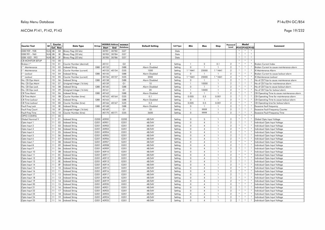
Relay Menu Database
MiCOM P141, P142, P143
P14x/EN GC/B54
Page 19/232
Col Row Start End P141 P142 P143Courier Text UI Data Type Strings
CourierCommentMODBUS
Database Default Setting Cell Type MinMODBUS Address Model
Max Step Password Level
DDB 959 - 928 N/A 0B 3D Binary Flag (32 bits) 30781 30782 G27 Data * * *DDB 991 - 960 N/A 0B 3E Binary Flag (32 bits) 30783 30784 G27 Data * * *DDB 1022 - 992 N/A 0B 3F Binary Flag (32 bits) 30785 30786 G27 Data * * *CB MONITOR SETUP 10 00 * * *Broken I^ 10 01 Courier Number (decimal) 40151 G2 2 Setting 1 2 0.1 2 * * * Broken Current IndexI^ Maintenance 10 02 Indexed String G88 40152 G88 Alarm Disabled Setting 0 1 1 2 * * * Broken Current to cause maintenance alarmI^ Maintenance 10 03 Courier Number (current) 40153 40154 G35 1000 Setting 1 * NM1 25000 1 * NM1 2 * * * IX Maintenance AlarmI^ Lockout 10 04 Indexed String G88 40155 G88 Alarm Disabled Setting 0 1 1 2 * * * Broken Current to cause lockout alarmI^ Lockout 10 05 Courier Number (current) 40156 40157 G35 2000 Setting 1 * NM1 25000 1 * NM1 2 * * * IX Maintenance LockoutNo. CB Ops Maint 10 06 Indexed String G88 40158 G88 Alarm Disabled Setting 0 1 1 2 * * * No of CB Trips to cause maintenance alarmNo. CB Ops Maint 10 07 Unsigned Integer (16 bits) 40159 G1 10 Setting 1 10000 1 2 * * * No of CB Trips for maintenance alarmNo. CB Ops Lock 10 08 Indexed String G88 40160 G88 Alarm Disabled Setting 0 1 1 2 * * * No of CB Trips to cause lockout alarmNo. CB Ops Lock 10 09 Unsigned Integer (16 bits) 40161 G1 20 Setting 1 10000 1 2 * * * No of CB Trips for lockout alarmCB Time Maint 10 0A Indexed String G88 40162 G88 Alarm Disabled Setting 0 1 1 2 * * * CB Operating Time to cause maintenance alarmCB Time Maint 10 0B Courier Number (time) 40163 40164 G35 0.1 Setting 0.005 0.5 0.001 2 * * * CB Operating Time for maintenance alarmCB Time Lockout 10 0C Indexed String G88 40165 G88 Alarm Disabled Setting 0 1 1 2 * * * CB Operating Time to cause lockout alarmCB Time Lockout 10 0D Courier Number (time) 40166 40167 G35 0.2 Setting 0.005 0.5 0.001 2 * * * CB Operating time for lockout alarmFault Freq Lock 10 0E Indexed String G88 40168 G88 Alarm Disabled Setting 0 1 1 2 * * * Excessive fault frequencyFault Freq Count 10 0F Unsigned Integer (16 bits) 40169 G1 10 Setting 1 9999 1 2 * * * Excessive Fault Frequency CounterFault Freq Time 10 10 Courier Number (time) 40170 40171 G35 3600 Setting 0 9999 1 2 * * * Excessive Fault Frequency TimeOPTO CONFIG 11 00 * * *Global Nominal V 11 01 Indexed String G200 40900 G200 48/54V Setting 0 5 1 2 * * * Global Opto Input VoltageOpto Input 1 11 02 Indexed String G201 40901 G201 48/54V Setting 0 4 1 2 * * * Individual Opto Input VoltageOpto Input 2 11 03 Indexed String G201 40902 G201 48/54V Setting 0 4 1 2 * * * Individual Opto Input VoltageOpto Input 3 11 04 Indexed String G201 40903 G201 48/54V Setting 0 4 1 2 * * * Individual Opto Input VoltageOpto Input 4 11 05 Indexed String G201 40904 G201 48/54V Setting 0 4 1 2 * * * Individual Opto Input VoltageOpto Input 5 11 06 Indexed String G201 40905 G201 48/54V Setting 0 4 1 2 * * * Individual Opto Input VoltageOpto Input 6 11 07 Indexed String G201 40906 G201 48/54V Setting 0 4 1 2 * * * Individual Opto Input VoltageOpto Input 7 11 08 Indexed String G201 40907 G201 48/54V Setting 0 4 1 2 * * * Individual Opto Input VoltageOpto Input 8 11 09 Indexed String G201 40908 G201 48/54V Setting 0 4 1 2 * * * Individual Opto Input VoltageOpto Input 9 11 0A Indexed String G201 40909 G201 48/54V Setting 0 4 1 2 * * * Individual Opto Input VoltageOpto Input 10 11 0B Indexed String G201 40910 G201 48/54V Setting 0 4 1 2 * * * Individual Opto Input VoltageOpto Input 11 11 0C Indexed String G201 40911 G201 48/54V Setting 0 4 1 2 * * * Individual Opto Input VoltageOpto Input 12 11 0D Indexed String G201 40912 G201 48/54V Setting 0 4 1 2 * * * Individual Opto Input VoltageOpto Input 13 11 0E Indexed String G201 40913 G201 48/54V Setting 0 4 1 2 * * * Individual Opto Input VoltageOpto Input 14 11 0F Indexed String G201 40914 G201 48/54V Setting 0 4 1 2 * * * Individual Opto Input VoltageOpto Input 15 11 10 Indexed String G201 40915 G201 48/54V Setting 0 4 1 2 * * * Individual Opto Input VoltageOpto Input 16 11 11 Indexed String G201 40916 G201 48/54V Setting 0 4 1 2 * * * Individual Opto Input VoltageOpto Input 17 11 12 Indexed String G201 40917 G201 48/54V Setting 0 4 1 2 * * * Individual Opto Input VoltageOpto Input 18 11 13 Indexed String G201 40918 G201 48/54V Setting 0 4 1 2 * * * Individual Opto Input VoltageOpto Input 19 11 14 Indexed String G201 40919 G201 48/54V Setting 0 4 1 2 * * * Individual Opto Input VoltageOpto Input 20 11 15 Indexed String G201 40920 G201 48/54V Setting 0 4 1 2 * * * Individual Opto Input VoltageOpto Input 21 11 16 Indexed String G201 40921 G201 48/54V Setting 0 4 1 2 * * * Individual Opto Input VoltageOpto Input 22 11 17 Indexed String G201 40922 G201 48/54V Setting 0 4 1 2 * * * Individual Opto Input VoltageOpto Input 23 11 18 Indexed String G201 40923 G201 48/54V Setting 0 4 1 2 * * * Individual Opto Input VoltageOpto Input 24 11 19 Indexed String G201 40924 G201 48/54V Setting 0 4 1 2 * * * Individual Opto Input VoltageOpto Input 25 11 1A Indexed String G201 40925 G201 48/54V Setting 0 4 1 2 * * * Individual Opto Input Voltage
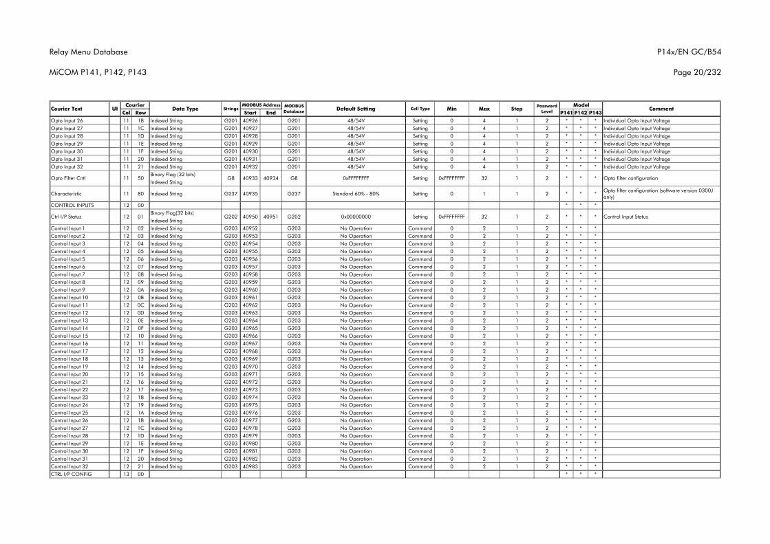
Relay Menu Database
MiCOM P141, P142, P143
P14x/EN GC/B54
Page 20/232
Col Row Start End P141 P142 P143Courier Text UI Data Type Strings
CourierCommentMODBUS
Database Default Setting Cell Type MinMODBUS Address Model
Max Step Password Level
Opto Input 26 11 1B Indexed String G201 40926 G201 48/54V Setting 0 4 1 2 * * * Individual Opto Input VoltageOpto Input 27 11 1C Indexed String G201 40927 G201 48/54V Setting 0 4 1 2 * * * Individual Opto Input VoltageOpto Input 28 11 1D Indexed String G201 40928 G201 48/54V Setting 0 4 1 2 * * * Individual Opto Input VoltageOpto Input 29 11 1E Indexed String G201 40929 G201 48/54V Setting 0 4 1 2 * * * Individual Opto Input VoltageOpto Input 30 11 1F Indexed String G201 40930 G201 48/54V Setting 0 4 1 2 * * * Individual Opto Input VoltageOpto Input 31 11 20 Indexed String G201 40931 G201 48/54V Setting 0 4 1 2 * * * Individual Opto Input VoltageOpto Input 32 11 21 Indexed String G201 40932 G201 48/54V Setting 0 4 1 2 * * * Individual Opto Input Voltage
Binary Flag (32 bits)Indexed String
Characteristic 11 80 Indexed String G237 40935 G237 Standard 60% - 80% Setting 0 1 1 2 * * *Opto filter configuration (software version 0300J only)
CONTROL INPUTS 12 00 * * *Binary Flag(32 bits)Indexed String
Control Input 1 12 02 Indexed String G203 40952 G203 No Operation Command 0 2 1 2 * * *Control Input 2 12 03 Indexed String G203 40953 G203 No Operation Command 0 2 1 2 * * *Control Input 3 12 04 Indexed String G203 40954 G203 No Operation Command 0 2 1 2 * * *Control Input 4 12 05 Indexed String G203 40955 G203 No Operation Command 0 2 1 2 * * *Control Input 5 12 06 Indexed String G203 40956 G203 No Operation Command 0 2 1 2 * * *Control Input 6 12 07 Indexed String G203 40957 G203 No Operation Command 0 2 1 2 * * *Control Input 7 12 08 Indexed String G203 40958 G203 No Operation Command 0 2 1 2 * * *Control Input 8 12 09 Indexed String G203 40959 G203 No Operation Command 0 2 1 2 * * *Control Input 9 12 0A Indexed String G203 40960 G203 No Operation Command 0 2 1 2 * * *Control Input 10 12 0B Indexed String G203 40961 G203 No Operation Command 0 2 1 2 * * *Control Input 11 12 0C Indexed String G203 40962 G203 No Operation Command 0 2 1 2 * * *Control Input 12 12 0D Indexed String G203 40963 G203 No Operation Command 0 2 1 2 * * *Control Input 13 12 0E Indexed String G203 40964 G203 No Operation Command 0 2 1 2 * * *Control Input 14 12 0F Indexed String G203 40965 G203 No Operation Command 0 2 1 2 * * *Control Input 15 12 10 Indexed String G203 40966 G203 No Operation Command 0 2 1 2 * * *Control Input 16 12 11 Indexed String G203 40967 G203 No Operation Command 0 2 1 2 * * *Control Input 17 12 12 Indexed String G203 40968 G203 No Operation Command 0 2 1 2 * * *Control Input 18 12 13 Indexed String G203 40969 G203 No Operation Command 0 2 1 2 * * *Control Input 19 12 14 Indexed String G203 40970 G203 No Operation Command 0 2 1 2 * * *Control Input 20 12 15 Indexed String G203 40971 G203 No Operation Command 0 2 1 2 * * *Control Input 21 12 16 Indexed String G203 40972 G203 No Operation Command 0 2 1 2 * * *Control Input 22 12 17 Indexed String G203 40973 G203 No Operation Command 0 2 1 2 * * *Control Input 23 12 18 Indexed String G203 40974 G203 No Operation Command 0 2 1 2 * * *Control Input 24 12 19 Indexed String G203 40975 G203 No Operation Command 0 2 1 2 * * *Control Input 25 12 1A Indexed String G203 40976 G203 No Operation Command 0 2 1 2 * * *Control Input 26 12 1B Indexed String G203 40977 G203 No Operation Command 0 2 1 2 * * *Control Input 27 12 1C Indexed String G203 40978 G203 No Operation Command 0 2 1 2 * * *Control Input 28 12 1D Indexed String G203 40979 G203 No Operation Command 0 2 1 2 * * *Control Input 29 12 1E Indexed String G203 40980 G203 No Operation Command 0 2 1 2 * * *Control Input 30 12 1F Indexed String G203 40981 G203 No Operation Command 0 2 1 2 * * *Control Input 31 12 20 Indexed String G203 40982 G203 No Operation Command 0 2 1 2 * * *Control Input 32 12 21 Indexed String G203 40983 G203 No Operation Command 0 2 1 2 * * *CTRL I/P CONFIG 13 00 * * *
* * Control Input Status32 1 2 *G202 0x00000000 Setting 0xFFFFFFFFCtrl I/P Status 12 01 G202 40950 40951
Opto Filter Cntl 11 50 G8 40933 40934 G8 0xFFFFFFFF Setting 0xFFFFFFFF 32 * Opto filter configuration1 2 * *
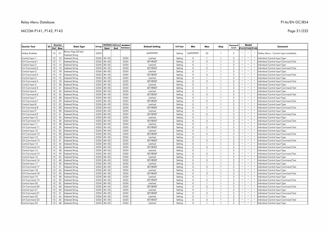
Relay Menu Database
MiCOM P141, P142, P143
P14x/EN GC/B54
Page 21/232
Col Row Start End P141 P142 P143Courier Text UI Data Type Strings
CourierCommentMODBUS
Database Default Setting Cell Type MinMODBUS Address Model
Max Step Password Level
Binary Flag (32 bits)Indexed String
Control Input 1 13 10 Indexed String G234 4E+05 G234 Latched Setting 0 1 1 2 * * * Individual Control Input TypeCtrl Command 1 13 11 Indexed String G232 4E+05 G232 SET/RESET Setting 0 3 1 2 * * * Individual Control Input Command TextControl Input 2 13 14 Indexed String G234 4E+05 G234 Latched Setting 0 1 1 2 * * * Individual Control Input TypeCtrl Command 2 13 15 Indexed String G232 4E+05 G232 SET/RESET Setting 0 3 1 2 * * * Individual Control Input Command TextControl Input 3 13 18 Indexed String G234 4E+05 G234 Latched Setting 0 1 1 2 * * * Individual Control Input TypeCtrl Command 3 13 19 Indexed String G232 4E+05 G232 SET/RESET Setting 0 3 1 2 * * * Individual Control Input Command TextControl Input 4 13 1C Indexed String G234 4E+05 G234 Latched Setting 0 1 1 2 * * * Individual Control Input TypeCtrl Command 4 13 1D Indexed String G232 4E+05 G232 SET/RESET Setting 0 3 1 2 * * * Individual Control Input Command TextControl Input 5 13 20 Indexed String G234 4E+05 G234 Latched Setting 0 1 1 2 * * * Individual Control Input TypeCtrl Command 5 13 21 Indexed String G232 4E+05 G232 SET/RESET Setting 0 3 1 2 * * * Individual Control Input Command TextControl Input 6 13 24 Indexed String G234 4E+05 G234 Latched Setting 0 1 1 2 * * * Individual Control Input TypeCtrl Command 6 13 25 Indexed String G232 4E+05 G232 SET/RESET Setting 0 3 1 2 * * * Individual Control Input Command TextControl Input 7 13 28 Indexed String G234 4E+05 G234 Latched Setting 0 1 1 2 * * * Individual Control Input TypeCtrl Command 7 13 29 Indexed String G232 4E+05 G232 SET/RESET Setting 0 3 1 2 * * * Individual Control Input Command TextControl Input 8 13 2C Indexed String G234 4E+05 G234 Latched Setting 0 1 1 2 * * * Individual Control Input TypeCtrl Command 8 13 2D Indexed String G232 4E+05 G232 SET/RESET Setting 0 3 1 2 * * * Individual Control Input Command TextControl Input 9 13 30 Indexed String G234 4E+05 G234 Latched Setting 0 1 1 2 * * * Individual Control Input TypeCtrl Command 9 13 31 Indexed String G232 4E+05 G232 SET/RESET Setting 0 3 1 2 * * * Individual Control Input Command TextControl Input 10 13 34 Indexed String G234 4E+05 G234 Latched Setting 0 1 1 2 * * * Individual Control Input TypeCtrl Command 10 13 35 Indexed String G232 4E+05 G232 SET/RESET Setting 0 3 1 2 * * * Individual Control Input Command TextControl Input 11 13 38 Indexed String G234 4E+05 G234 Latched Setting 0 1 1 2 * * * Individual Control Input TypeCtrl Command 11 13 39 Indexed String G232 4E+05 G232 SET/RESET Setting 0 3 1 2 * * * Individual Control Input Command TextControl Input 12 13 3C Indexed String G234 4E+05 G234 Latched Setting 0 1 1 2 * * * Individual Control Input TypeCtrl Command 12 13 3D Indexed String G232 4E+05 G232 SET/RESET Setting 0 3 1 2 * * * Individual Control Input Command TextControl Input 13 13 40 Indexed String G234 4E+05 G234 Latched Setting 0 1 1 2 * * * Individual Control Input TypeCtrl Command 13 13 41 Indexed String G232 4E+05 G232 SET/RESET Setting 0 3 1 2 * * * Individual Control Input Command TextControl Input 14 13 44 Indexed String G234 4E+05 G234 Latched Setting 0 1 1 2 * * * Individual Control Input TypeCtrl Command 14 13 45 Indexed String G232 4E+05 G232 SET/RESET Setting 0 3 1 2 * * * Individual Control Input Command TextControl Input 15 13 48 Indexed String G234 4E+05 G234 Latched Setting 0 1 1 2 * * * Individual Control Input TypeCtrl Command 15 13 49 Indexed String G232 4E+05 G232 SET/RESET Setting 0 3 1 2 * * * Individual Control Input Command TextControl Input 16 13 4C Indexed String G234 4E+05 G234 Latched Setting 0 1 1 2 * * * Individual Control Input TypeCtrl Command 16 13 4D Indexed String G232 4E+05 G232 SET/RESET Setting 0 3 1 2 * * * Individual Control Input Command TextControl Input 17 13 50 Indexed String G234 4E+05 G234 Latched Setting 0 1 1 2 * * * Individual Control Input TypeCtrl Command 17 13 51 Indexed String G232 4E+05 G232 SET/RESET Setting 0 3 1 2 * * * Individual Control Input Command TextControl Input 18 13 54 Indexed String G234 4E+05 G234 Latched Setting 0 1 1 2 * * * Individual Control Input TypeCtrl Command 18 13 55 Indexed String G232 4E+05 G232 SET/RESET Setting 0 3 1 2 * * * Individual Control Input Command TextControl Input 19 13 58 Indexed String G234 4E+05 G234 Latched Setting 0 1 1 2 * * * Individual Control Input TypeCtrl Command 19 13 59 Indexed String G232 4E+05 G232 SET/RESET Setting 0 3 1 2 * * * Individual Control Input Command TextControl Input 20 13 5C Indexed String G234 4E+05 G234 Latched Setting 0 1 1 2 * * * Individual Control Input TypeCtrl Command 20 13 5D Indexed String G232 4E+05 G232 SET/RESET Setting 0 3 1 2 * * * Individual Control Input Command TextControl Input 21 13 60 Indexed String G234 4E+05 G234 Latched Setting 0 1 1 2 * * * Individual Control Input TypeCtrl Command 21 13 61 Indexed String G232 4E+05 G232 SET/RESET Setting 0 3 1 2 * * * Individual Control Input Command TextControl Input 22 13 64 Indexed String G234 4E+05 G234 Latched Setting 0 1 1 2 * * * Individual Control Input TypeCtrl Command 22 13 65 Indexed String G232 4E+05 G232 SET/RESET Setting 0 3 1 2 * * * Individual Control Input Command TextControl Input 23 13 68 Indexed String G234 4E+05 G234 Latched Setting 0 1 1 2 * * * Individual Control Input Type
* Hotkey Menu - Control Input availability1 2 * *0xFFFFFFFF Setting 0xFFFFFFFF 32Hotkey Enabled 13 01 G233
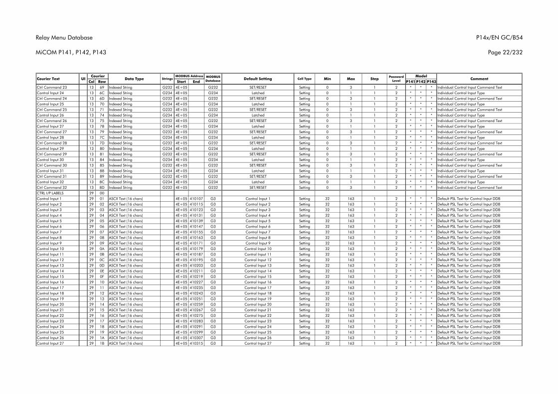
Relay Menu Database
MiCOM P141, P142, P143
P14x/EN GC/B54
Page 22/232
Col Row Start End P141 P142 P143Courier Text UI Data Type Strings
CourierCommentMODBUS
Database Default Setting Cell Type MinMODBUS Address Model
Max Step Password Level
Ctrl Command 23 13 69 Indexed String G232 4E+05 G232 SET/RESET Setting 0 3 1 2 * * * Individual Control Input Command TextControl Input 24 13 6C Indexed String G234 4E+05 G234 Latched Setting 0 1 1 2 * * * Individual Control Input TypeCtrl Command 24 13 6D Indexed String G232 4E+05 G232 SET/RESET Setting 0 3 1 2 * * * Individual Control Input Command TextControl Input 25 13 70 Indexed String G234 4E+05 G234 Latched Setting 0 1 1 2 * * * Individual Control Input TypeCtrl Command 25 13 71 Indexed String G232 4E+05 G232 SET/RESET Setting 0 3 1 2 * * * Individual Control Input Command TextControl Input 26 13 74 Indexed String G234 4E+05 G234 Latched Setting 0 1 1 2 * * * Individual Control Input TypeCtrl Command 26 13 75 Indexed String G232 4E+05 G232 SET/RESET Setting 0 3 1 2 * * * Individual Control Input Command TextControl Input 27 13 78 Indexed String G234 4E+05 G234 Latched Setting 0 1 1 2 * * * Individual Control Input TypeCtrl Command 27 13 79 Indexed String G232 4E+05 G232 SET/RESET Setting 0 3 1 2 * * * Individual Control Input Command TextControl Input 28 13 7C Indexed String G234 4E+05 G234 Latched Setting 0 1 1 2 * * * Individual Control Input TypeCtrl Command 28 13 7D Indexed String G232 4E+05 G232 SET/RESET Setting 0 3 1 2 * * * Individual Control Input Command TextControl Input 29 13 80 Indexed String G234 4E+05 G234 Latched Setting 0 1 1 2 * * * Individual Control Input TypeCtrl Command 29 13 81 Indexed String G232 4E+05 G232 SET/RESET Setting 0 3 1 2 * * * Individual Control Input Command TextControl Input 30 13 84 Indexed String G234 4E+05 G234 Latched Setting 0 1 1 2 * * * Individual Control Input TypeCtrl Command 30 13 85 Indexed String G232 4E+05 G232 SET/RESET Setting 0 3 1 2 * * * Individual Control Input Command TextControl Input 31 13 88 Indexed String G234 4E+05 G234 Latched Setting 0 1 1 2 * * * Individual Control Input TypeCtrl Command 31 13 89 Indexed String G232 4E+05 G232 SET/RESET Setting 0 3 1 2 * * * Individual Control Input Command TextControl Input 32 13 8C Indexed String G234 4E+05 G234 Latched Setting 0 1 1 2 * * * Individual Control Input TypeCtrl Command 32 13 8D Indexed String G232 4E+05 G232 SET/RESET Setting 0 3 1 2 * * * Individual Control Input Command TextCTRL I/P LABELS 29 00Control Input 1 29 01 ASCII Text (16 chars) 4E+05 410107 G3 Control Input 1 Setting 32 163 1 2 * * * Default PSL Text for Control Input DDBControl Input 2 29 02 ASCII Text (16 chars) 4E+05 410115 G3 Control Input 2 Setting 32 163 1 2 * * * Default PSL Text for Control Input DDBControl Input 3 29 03 ASCII Text (16 chars) 4E+05 410123 G3 Control Input 3 Setting 32 163 1 2 * * * Default PSL Text for Control Input DDBControl Input 4 29 04 ASCII Text (16 chars) 4E+05 410131 G3 Control Input 4 Setting 32 163 1 2 * * * Default PSL Text for Control Input DDBControl Input 5 29 05 ASCII Text (16 chars) 4E+05 410139 G3 Control Input 5 Setting 32 163 1 2 * * * Default PSL Text for Control Input DDBControl Input 6 29 06 ASCII Text (16 chars) 4E+05 410147 G3 Control Input 6 Setting 32 163 1 2 * * * Default PSL Text for Control Input DDBControl Input 7 29 07 ASCII Text (16 chars) 4E+05 410155 G3 Control Input 7 Setting 32 163 1 2 * * * Default PSL Text for Control Input DDBControl Input 8 29 08 ASCII Text (16 chars) 4E+05 410163 G3 Control Input 8 Setting 32 163 1 2 * * * Default PSL Text for Control Input DDBControl Input 9 29 09 ASCII Text (16 chars) 4E+05 410171 G3 Control Input 9 Setting 32 163 1 2 * * * Default PSL Text for Control Input DDBControl Input 10 29 0A ASCII Text (16 chars) 4E+05 410179 G3 Control Input 10 Setting 32 163 1 2 * * * Default PSL Text for Control Input DDBControl Input 11 29 0B ASCII Text (16 chars) 4E+05 410187 G3 Control Input 11 Setting 32 163 1 2 * * * Default PSL Text for Control Input DDBControl Input 12 29 0C ASCII Text (16 chars) 4E+05 410195 G3 Control Input 12 Setting 32 163 1 2 * * * Default PSL Text for Control Input DDBControl Input 13 29 0D ASCII Text (16 chars) 4E+05 410203 G3 Control Input 13 Setting 32 163 1 2 * * * Default PSL Text for Control Input DDBControl Input 14 29 0E ASCII Text (16 chars) 4E+05 410211 G3 Control Input 14 Setting 32 163 1 2 * * * Default PSL Text for Control Input DDBControl Input 15 29 0F ASCII Text (16 chars) 4E+05 410219 G3 Control Input 15 Setting 32 163 1 2 * * * Default PSL Text for Control Input DDBControl Input 16 29 10 ASCII Text (16 chars) 4E+05 410227 G3 Control Input 16 Setting 32 163 1 2 * * * Default PSL Text for Control Input DDBControl Input 17 29 11 ASCII Text (16 chars) 4E+05 410235 G3 Control Input 17 Setting 32 163 1 2 * * * Default PSL Text for Control Input DDBControl Input 18 29 12 ASCII Text (16 chars) 4E+05 410243 G3 Control Input 18 Setting 32 163 1 2 * * * Default PSL Text for Control Input DDBControl Input 19 29 13 ASCII Text (16 chars) 4E+05 410251 G3 Control Input 19 Setting 32 163 1 2 * * * Default PSL Text for Control Input DDBControl Input 20 29 14 ASCII Text (16 chars) 4E+05 410259 G3 Control Input 20 Setting 32 163 1 2 * * * Default PSL Text for Control Input DDBControl Input 21 29 15 ASCII Text (16 chars) 4E+05 410267 G3 Control Input 21 Setting 32 163 1 2 * * * Default PSL Text for Control Input DDBControl Input 22 29 16 ASCII Text (16 chars) 4E+05 410275 G3 Control Input 22 Setting 32 163 1 2 * * * Default PSL Text for Control Input DDBControl Input 23 29 17 ASCII Text (16 chars) 4E+05 410283 G3 Control Input 23 Setting 32 163 1 2 * * * Default PSL Text for Control Input DDBControl Input 24 29 18 ASCII Text (16 chars) 4E+05 410291 G3 Control Input 24 Setting 32 163 1 2 * * * Default PSL Text for Control Input DDBControl Input 25 29 19 ASCII Text (16 chars) 4E+05 410299 G3 Control Input 25 Setting 32 163 1 2 * * * Default PSL Text for Control Input DDBControl Input 26 29 1A ASCII Text (16 chars) 4E+05 410307 G3 Control Input 26 Setting 32 163 1 2 * * * Default PSL Text for Control Input DDBControl Input 27 29 1B ASCII Text (16 chars) 4E+05 410315 G3 Control Input 27 Setting 32 163 1 2 * * * Default PSL Text for Control Input DDB
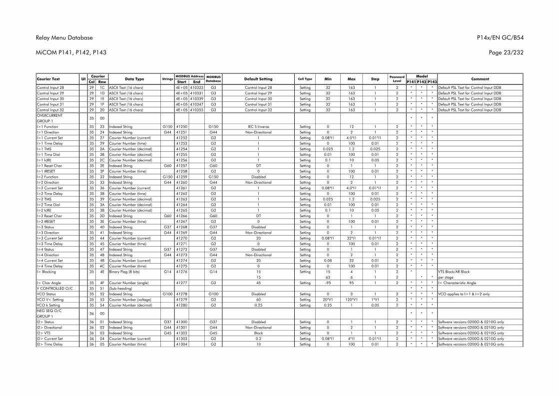
Relay Menu Database
MiCOM P141, P142, P143
P14x/EN GC/B54
Page 23/232
Col Row Start End P141 P142 P143Courier Text UI Data Type Strings
CourierCommentMODBUS
Database Default Setting Cell Type MinMODBUS Address Model
Max Step Password Level
Control Input 28 29 1C ASCII Text (16 chars) 4E+05 410323 G3 Control Input 28 Setting 32 163 1 2 * * * Default PSL Text for Control Input DDBControl Input 29 29 1D ASCII Text (16 chars) 4E+05 410331 G3 Control Input 29 Setting 32 163 1 2 * * * Default PSL Text for Control Input DDBControl Input 30 29 1E ASCII Text (16 chars) 4E+05 410339 G3 Control Input 30 Setting 32 163 1 2 * * * Default PSL Text for Control Input DDBControl Input 31 29 1F ASCII Text (16 chars) 4E+05 410347 G3 Control Input 31 Setting 32 163 1 2 * * * Default PSL Text for Control Input DDBControl Input 32 29 20 ASCII Text (16 chars) 4E+05 410355 G3 Control Input 32 Setting 32 163 1 2 * * * Default PSL Text for Control Input DDBOVERCURRENTGROUP 1I>1 Function 35 23 Indexed String G150 41250 G150 IEC S Inverse Setting 0 12 1 2 * * *I>1 Direction 35 24 Indexed String G44 41251 G44 Non-Directional Setting 0 2 1 2 * * *I>1 Current Set 35 27 Courier Number (current) 41252 G2 1 Setting 0.08*I1 4.0*I1 0.01*I1 2 * * *I>1 Time Delay 35 29 Courier Number (time) 41253 G2 1 Setting 0 100 0.01 2 * * *I>1 TMS 35 2A Courier Number (decimal) 41254 G2 1 Setting 0.025 1.2 0.025 2 * * *I>1 Time Dial 35 2B Courier Number (decimal) 41255 G2 1 Setting 0.01 100 0.01 2 * * *I>1 k(RI) 35 2C Courier Number (decimal) 41256 G2 1 Setting 0.1 10 0.05 2 * * *I>1 Reset Char 35 2E Indexed String G60 41257 G60 DT Setting 0 1 1 2 * * *I>1 tRESET 35 2F Courier Number (time) 41258 G2 0 Setting 0 100 0.01 2 * * *I>2 Function 35 32 Indexed String G150 41259 G150 Disabled Setting 0 12 1 2 * * *I>2 Direction 35 33 Indexed String G44 41260 G44 Non-Directional Setting 0 2 1 2 * * *I>2 Current Set 35 36 Courier Number (current) 41261 G2 1 Setting 0.08*I1 4.0*I1 0.01*I1 2 * * *I>2 Time Delay 35 38 Courier Number (time) 41262 G2 1 Setting 0 100 0.01 2 * * *I>2 TMS 35 39 Courier Number (decimal) 41263 G2 1 Setting 0.025 1.2 0.025 2 * * *I>2 Time Dial 35 3A Courier Number (decimal) 41264 G2 1 Setting 0.01 100 0.01 2 * * *I>2 k(RI) 35 3B Courier Number (decimal) 41265 G2 1 Setting 0.1 10 0.05 2 * * *I>2 Reset Char 35 3D Indexed String G60 41266 G60 DT Setting 0 1 1 2 * * *I>2 tRESET 35 3E Courier Number (time) 41267 G2 0 Setting 0 100 0.01 2 * * *I>3 Status 35 40 Indexed String G37 41268 G37 Disabled Setting 0 1 1 2 * * *I>3 Direction 35 41 Indexed String G44 41269 G44 Non-Directional Setting 0 2 1 2 * * *I>3 Current Set 35 44 Courier Number (current) 41270 G2 20 Setting 0.08*I1 32*I1 0.01*I1 2 * * *I>3 Time Delay 35 45 Courier Number (time) 41271 G2 0 Setting 0 100 0.01 2 * * *I>4 Status 35 47 Indexed String G37 41272 G37 Disabled Setting 0 1 1 2 * * *I>4 Direction 35 48 Indexed String G44 41273 G44 Non-Directional Setting 0 2 1 2 * * *I>4 Current Set 35 4B Courier Number (current) 41274 G2 20 Setting 0.08 32 0.01 2 * * *I>4 Time Delay 35 4C Courier Number (time) 41275 G2 0 Setting 0 100 0.01 2 * * *I> Blocking 35 4E Binary Flag (8 bits) G14 41276 G14 15 Setting 15 4 1 2 * VTS Block/AR Block
15 63 6 1 2 * * per stageI> Char Angle 35 4F Courier Number (angle) 41277 G2 45 Setting -95 95 1 2 * * * I> Characteristic AngleV CONTROLLED O/C 35 51 (Sub-heading) * * *VCO Status 35 52 Indexed String G100 41278 G100 Disabled Setting 0 3 1 2 * * * VCO applies to I>1 & I>2 onlyVCO V< Setting 35 53 Courier Number (voltage) 41279 G2 60 Setting 20*V1 120*V1 1*V1 2 * * *VCO k Setting 35 54 Courier Number (decimal) 41280 G2 0.25 Setting 0.25 1 0.05 2 * * *NEG SEQ O/CGROUP 1I2> Status 36 01 Indexed String G37 41300 G37 Disabled Setting 0 1 1 2 * * * Software versions 0200G & 0210G onlyI2> Directional 36 02 Indexed String G44 41301 G44 Non-Directional Setting 0 2 1 2 * * * Software versions 0200G & 0210G onlyI2> VTS 36 03 Indexed String G45 41302 G45 Block Setting 0 1 1 2 * * * Software versions 0200G & 0210G onlyI2> Current Set 36 04 Courier Number (current) 41303 G2 0.2 Setting 0.08*I1 4*I1 0.01*I1 2 * * * Software versions 0200G & 0210G onlyI2> Time Delay 36 05 Courier Number (time) 41304 G2 10 Setting 0 100 0.01 2 * * * Software versions 0200G & 0210G only
*36 00 * *
35 00 * * *
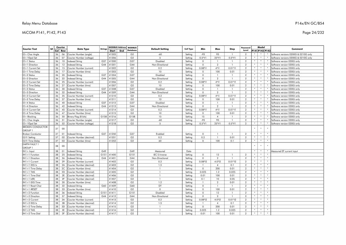
Relay Menu Database
MiCOM P141, P142, P143
P14x/EN GC/B54
Page 24/232
Col Row Start End P141 P142 P143Courier Text UI Data Type Strings
CourierCommentMODBUS
Database Default Setting Cell Type MinMODBUS Address Model
Max Step Password Level
I2> Char Angle 36 06 Courier Number (angle) 41305 G2 -60 Setting -95 95 1 2 * * * Software versions 0200G & 0210G onlyI2> V2pol Set 36 07 Courier Number (voltage) 41306 G2 5 Setting 0.5*V1 25*V1 0.5*V1 2 * * * Software versions 0200G & 0210G onlyI2>1 Status 36 10 Indexed String G37 41300 G37 Disabled Setting 0 1 1 2 * * * Software version 0300J onlyI2>1 Direction 36 12 Indexed String G44 41301 G44 Non-Directional Setting 0 2 1 2 * * * Software version 0300J onlyI2>1 Current Set 36 15 Courier Number (current) 41302 G2 0.2 Setting 0.08*I1 4*I1 0.01*I1 2 * * * Software version 0300J onlyI2>1 Time Delay 36 17 Courier Number (time) 41303 G2 10 Setting 0 100 0.01 2 * * * Software version 0300J onlyI2>2 Status 36 20 Indexed String G37 41304 G37 Disabled Setting 0 1 1 2 * * * Software version 0300J onlyI2>2 Direction 36 22 Indexed String G44 41305 G44 Non-Directional Setting 0 2 1 2 * * * Software version 0300J onlyI2>2 Current Set 36 25 Courier Number (current) 41306 G2 0.2 Setting 0.08*I1 4*I1 0.01*I1 2 * * * Software version 0300J onlyI2>2 Time Delay 36 27 Courier Number (time) 41307 G2 10 Setting 0 100 0.01 2 * * * Software version 0300J onlyI2>3 Status 36 30 Indexed String G37 41308 G37 Disabled Setting 0 1 1 2 * * * Software version 0300J onlyI2>3 Direction 36 32 Indexed String G44 41309 G44 Non-Directional Setting 0 2 1 2 * * * Software version 0300J onlyI2>3 Current Set 36 35 Courier Number (current) 41310 G2 0.2 Setting 0.08*I1 4*I1 0.01*I1 2 * * * Software version 0300J onlyI2>3 Time Delay 36 37 Courier Number (time) 41311 G2 10 Setting 0 100 0.01 2 * * * Software version 0300J onlyI2>4 Status 36 40 Indexed String G37 41312 G37 Disabled Setting 0 1 1 2 * * * Software version 0300J onlyI2>4 Direction 36 42 Indexed String G44 41313 G44 Non-Directional Setting 0 2 1 2 * * * Software version 0300J onlyI2>4 Current Set 36 45 Courier Number (current) 41314 G2 0.2 Setting 0.08*I1 4*I1 0.01*I1 2 * * * Software version 0300J onlyI2>4 Time Delay 36 47 Courier Number (time) 41315 G2 10 Setting 0 100 0.01 2 * * * Software version 0300J onlyI2> Blocking 36 50 Binary Flag (8 bits) G158 41316 G158 15 Setting 15 4 1 2 * * * Software version 0300J onlyI2> Char Angle 36 51 Courier Number (angle) 41317 G2 -60 Setting -95 95 1 2 * * * Software version 0300J onlyI2> V2pol Set 36 52 Courier Number (voltage) 41318 G2 5 Setting 0.5*V1 25*V1 0.5*V1 2 * * * Software version 0300J onlyBROKEN CONDUCTORGROUP 1Broken Conductor 37 01 Indexed String G37 41350 G37 Enabled Setting 0 1 1 2 * * *I2/I1 Setting 37 02 Courier Number (decimal) 41351 G2 0.2 Setting 0.2 1 0.01 2 * * *I2/I1 Time Delay 37 03 Courier Number (time) 41352 G2 60 Setting 0 100 0.1 2 * * *EARTH FAULT 1GROUP 1IN1> Input 38 01 Indexed String G49 G49 Measured Data * * * Measured EF current inputIN1>1 Function 38 25 Indexed String G151 41400 G151 IEC S Inverse Setting 0 12 1 2 * * *IN1>1 Direction 38 26 Indexed String G44 41401 G44 Non-Directional Setting 0 2 1 2 * * *IN1>1 Current 38 29 Courier Number (current) 41402 G2 0.2 Setting 0.08*I2 4.0*I2 0.01*I2 2 * * *IN1>1 IDG Is 38 2A Courier Number (decimal) 41403 G2 1.5 Setting 1 4 0.1 2 * * *IN1>1 Time Delay 38 2C Courier Number (time) 41404 G2 1 Setting 0 200 0.01 2 * * *IN1>1 TMS 38 2D Courier Number (decimal) 41405 G2 1 Setting 0.025 1.2 0.025 2 * * *IN1>1 Time Dial 38 2E Courier Number (decimal) 41406 G2 1 Setting 0.01 100 0.01 2 * * *IN1>1 k(RI) 38 2F Courier Number (decimal) 41407 G2 1 Setting 0.1 10 0.05 2 * * *IN1>1 IDG Time 38 30 Courier Number (time) 41408 G2 1.2 Setting 1 2 0.01 2 * * *IN1>1 Reset Char 38 32 Indexed String G60 41409 G60 DT Setting 0 1 1 2 * * *IN1>1 tRESET 38 33 Courier Number (time) 41410 G2 0 Setting 0 100 0.01 2 * * *IN1>2 Function 38 36 Indexed String G151 41411 G151 Disabled Setting 0 12 1 2 * * *IN1>2 Direction 38 37 Indexed String G44 41412 G44 Non-Directional Setting 0 2 1 2 * * *IN1>2 Current 38 3A Courier Number (current) 41413 G2 0.2 Setting 0.08*I2 4.0*I2 0.01*I2 2 * * *IN1>2 IDG Is 38 3B Courier Number (decimal) 41414 G2 1.5 Setting 1 4 0.1 2 * * *IN1>2 Time Delay 38 3D Courier Number (time) 41415 G2 1 Setting 0 200 0.01 2 * * *IN1>2 TMS 38 3E Courier Number (decimal) 41416 G2 1 Setting 0.025 1.2 0.025 2 * * *IN1>2 Time Dial 38 3F Courier Number (decimal) 41417 G2 1 Setting 0.01 100 0.01 2 * * *
*38 00 * *
37 00 * * *
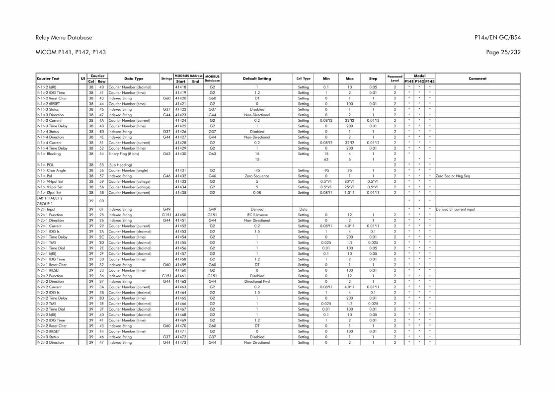
Relay Menu Database
MiCOM P141, P142, P143
P14x/EN GC/B54
Page 25/232
Col Row Start End P141 P142 P143Courier Text UI Data Type Strings
CourierCommentMODBUS
Database Default Setting Cell Type MinMODBUS Address Model
Max Step Password Level
IN1>2 k(RI) 38 40 Courier Number (decimal) 41418 G2 1 Setting 0.1 10 0.05 2 * * *IN1>2 IDG Time 38 41 Courier Number (time) 41419 G2 1.2 Setting 1 2 0.01 2 * * *IN1>2 Reset Char 38 43 Indexed String G60 41420 G60 DT Setting 0 1 1 2 * * *IN1>2 tRESET 38 44 Courier Number (time) 41421 G2 0 Setting 0 100 0.01 2 * * *IN1>3 Status 38 46 Indexed String G37 41422 G37 Disabled Setting 0 1 1 2 * * *IN1>3 Direction 38 47 Indexed String G44 41423 G44 Non-Directional Setting 0 2 1 2 * * *IN1>3 Current 38 4A Courier Number (current) 41424 G2 0.2 Setting 0.08*I2 32*I2 0.01*I2 2 * * *IN1>3 Time Delay 38 4B Courier Number (time) 41425 G2 1 Setting 0 200 0.01 2 * * *IN1>4 Status 38 4D Indexed String G37 41426 G37 Disabled Setting 0 1 1 2 * * *IN1>4 Direction 38 4E Indexed String G44 41427 G44 Non-Directional Setting 0 2 1 2 * * *IN1>4 Current 38 51 Courier Number (current) 41428 G2 0.2 Setting 0.08*I2 32*I2 0.01*I2 2 * * *IN1>4 Time Delay 38 52 Courier Number (time) 41429 G2 1 Setting 0 200 0.01 2 * * *IN1> Blocking 38 54 Binary Flag (8 bits) G63 41430 G63 15 Setting 15 4 1 2 *
15 63 6 1 2 * *IN1> POL 38 55 (Sub Heading) 2 * * *IN1> Char Angle 38 56 Courier Number (angle) 41431 G2 -45 Setting -95 95 1 2 * * *IN1> Pol 38 57 Indexed String G46 41432 G46 Zero Sequence Setting 0 1 1 2 * * * Zero Seq or Neg SeqIN1> VNpol Set 38 59 Courier Number (voltage) 41433 G2 5 Setting 0.5*V1 80*V1 0.5*V1 2 * * *IN1> V2pol Set 38 5A Courier Number (voltage) 41434 G2 5 Setting 0.5*V1 25*V1 0.5*V1 2 * * *IN1> I2pol Set 38 5B Courier Number (current) 41435 G2 0.08 Setting 0.08*I1 1.0*I1 0.01*I1 2 * * *EARTH FAULT 2GROUP 1IN2> Input 39 01 Indexed String G49 G49 Derived Data * * * Derived EF current inputIN2>1 Function 39 25 Indexed String G151 41450 G151 IEC S Inverse Setting 0 12 1 2 * * *IN2>1 Direction 39 26 Indexed String G44 41451 G44 Non-Directional Setting 0 2 1 2 * * *IN2>1 Current 39 29 Courier Number (current) 41452 G2 0.2 Setting 0.08*I1 4.0*I1 0.01*I1 2 * * *IN2>1 IDG Is 39 2A Courier Number (decimal) 41453 G2 1.5 Setting 1 4 0.1 2 * * *IN2>1 Time Delay 39 2C Courier Number (time) 41454 G2 1 Setting 0 200 0.01 2 * * *IN2>1 TMS 39 2D Courier Number (decimal) 41455 G2 1 Setting 0.025 1.2 0.025 2 * * *IN2>1 Time Dial 39 2E Courier Number (decimal) 41456 G2 1 Setting 0.01 100 0.05 2 * * *IN2>1 k(RI) 39 2F Courier Number (decimal) 41457 G2 1 Setting 0.1 10 0.05 2 * * *IN2>1 IDG Time 39 30 Courier Number (time) 41458 G2 1.2 Setting 1 2 0.01 2 * * *IN2>1 Reset Char 39 32 Indexed String G60 41459 G60 DT Setting 0 1 1 2 * * *IN2>1 tRESET 39 33 Courier Number (time) 41460 G2 0 Setting 0 100 0.01 2 * * *IN2>2 Function 39 36 Indexed String G151 41461 G151 Disabled Setting 0 12 1 2 * * *IN2>2 Direction 39 37 Indexed String G44 41462 G44 Directional Fwd Setting 0 2 1 2 * * *IN2>2 Current 39 3A Courier Number (current) 41463 G2 0.2 Setting 0.08*I1 4.0*I1 0.01*I1 2 * * *IN2>2 IDG Is 39 3B Courier Number (decimal) 41464 G2 1.5 Setting 1 4 0.1 2 * * *IN2>2 Time Delay 39 3D Courier Number (time) 41465 G2 1 Setting 0 200 0.01 2 * * *IN2>2 TMS 39 3E Courier Number (decimal) 41466 G2 1 Setting 0.025 1.2 0.025 2 * * *IN2>2 Time Dial 39 3F Courier Number (decimal) 41467 G2 1 Setting 0.01 100 0.01 2 * * *IN2>2 k(RI) 39 40 Courier Number (decimal) 41468 G2 1 Setting 0.1 10 0.05 2 * * *IN2>2 IDG Time 39 41 Courier Number (time) 41469 G2 1.2 Setting 1 2 0.01 2 * * *IN2>2 Reset Char 39 43 Indexed String G60 41470 G60 DT Setting 0 1 1 2 * * *IN2>2 tRESET 39 44 Courier Number (time) 41471 G2 0 Setting 0 100 0.01 2 * * *IN2>3 Status 39 46 Indexed String G37 41472 G37 Disabled Setting 0 1 1 2 * * *IN2>3 Direction 39 47 Indexed String G44 41473 G44 Non-Directional Setting 0 2 1 2 * * *
39 00 * * *
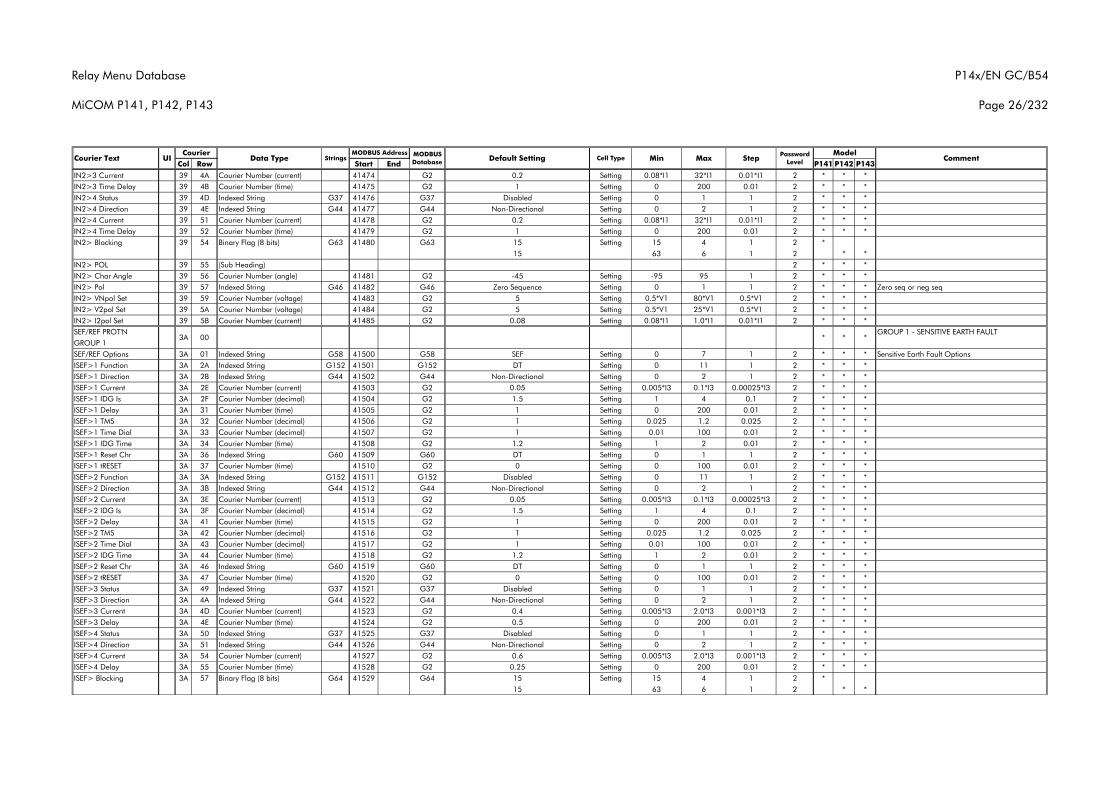
Relay Menu Database
MiCOM P141, P142, P143
P14x/EN GC/B54
Page 26/232
Col Row Start End P141 P142 P143Courier Text UI Data Type Strings
CourierCommentMODBUS
Database Default Setting Cell Type MinMODBUS Address Model
Max Step Password Level
IN2>3 Current 39 4A Courier Number (current) 41474 G2 0.2 Setting 0.08*I1 32*I1 0.01*I1 2 * * *IN2>3 Time Delay 39 4B Courier Number (time) 41475 G2 1 Setting 0 200 0.01 2 * * *IN2>4 Status 39 4D Indexed String G37 41476 G37 Disabled Setting 0 1 1 2 * * *IN2>4 Direction 39 4E Indexed String G44 41477 G44 Non-Directional Setting 0 2 1 2 * * *IN2>4 Current 39 51 Courier Number (current) 41478 G2 0.2 Setting 0.08*I1 32*I1 0.01*I1 2 * * *IN2>4 Time Delay 39 52 Courier Number (time) 41479 G2 1 Setting 0 200 0.01 2 * * *IN2> Blocking 39 54 Binary Flag (8 bits) G63 41480 G63 15 Setting 15 4 1 2 *
15 63 6 1 2 * *IN2> POL 39 55 (Sub Heading) 2 * * *IN2> Char Angle 39 56 Courier Number (angle) 41481 G2 -45 Setting -95 95 1 2 * * *IN2> Pol 39 57 Indexed String G46 41482 G46 Zero Sequence Setting 0 1 1 2 * * * Zero seq or neg seqIN2> VNpol Set 39 59 Courier Number (voltage) 41483 G2 5 Setting 0.5*V1 80*V1 0.5*V1 2 * * *IN2> V2pol Set 39 5A Courier Number (voltage) 41484 G2 5 Setting 0.5*V1 25*V1 0.5*V1 2 * * *IN2> I2pol Set 39 5B Courier Number (current) 41485 G2 0.08 Setting 0.08*I1 1.0*I1 0.01*I1 2 * * *SEF/REF PROT'N GROUP 1 - SENSITIVE EARTH FAULTGROUP 1SEF/REF Options 3A 01 Indexed String G58 41500 G58 SEF Setting 0 7 1 2 * * * Sensitive Earth Fault OptionsISEF>1 Function 3A 2A Indexed String G152 41501 G152 DT Setting 0 11 1 2 * * *ISEF>1 Direction 3A 2B Indexed String G44 41502 G44 Non-Directional Setting 0 2 1 2 * * *ISEF>1 Current 3A 2E Courier Number (current) 41503 G2 0.05 Setting 0.005*I3 0.1*I3 0.00025*I3 2 * * *ISEF>1 IDG Is 3A 2F Courier Number (decimal) 41504 G2 1.5 Setting 1 4 0.1 2 * * *ISEF>1 Delay 3A 31 Courier Number (time) 41505 G2 1 Setting 0 200 0.01 2 * * *ISEF>1 TMS 3A 32 Courier Number (decimal) 41506 G2 1 Setting 0.025 1.2 0.025 2 * * *ISEF>1 Time Dial 3A 33 Courier Number (decimal) 41507 G2 1 Setting 0.01 100 0.01 2 * * *ISEF>1 IDG Time 3A 34 Courier Number (time) 41508 G2 1.2 Setting 1 2 0.01 2 * * *ISEF>1 Reset Chr 3A 36 Indexed String G60 41509 G60 DT Setting 0 1 1 2 * * *ISEF>1 tRESET 3A 37 Courier Number (time) 41510 G2 0 Setting 0 100 0.01 2 * * *ISEF>2 Function 3A 3A Indexed String G152 41511 G152 Disabled Setting 0 11 1 2 * * *ISEF>2 Direction 3A 3B Indexed String G44 41512 G44 Non-Directional Setting 0 2 1 2 * * *ISEF>2 Current 3A 3E Courier Number (current) 41513 G2 0.05 Setting 0.005*I3 0.1*I3 0.00025*I3 2 * * *ISEF>2 IDG Is 3A 3F Courier Number (decimal) 41514 G2 1.5 Setting 1 4 0.1 2 * * *ISEF>2 Delay 3A 41 Courier Number (time) 41515 G2 1 Setting 0 200 0.01 2 * * *ISEF>2 TMS 3A 42 Courier Number (decimal) 41516 G2 1 Setting 0.025 1.2 0.025 2 * * *ISEF>2 Time Dial 3A 43 Courier Number (decimal) 41517 G2 1 Setting 0.01 100 0.01 2 * * *ISEF>2 IDG Time 3A 44 Courier Number (time) 41518 G2 1.2 Setting 1 2 0.01 2 * * *ISEF>2 Reset Chr 3A 46 Indexed String G60 41519 G60 DT Setting 0 1 1 2 * * *ISEF>2 tRESET 3A 47 Courier Number (time) 41520 G2 0 Setting 0 100 0.01 2 * * *ISEF>3 Status 3A 49 Indexed String G37 41521 G37 Disabled Setting 0 1 1 2 * * *ISEF>3 Direction 3A 4A Indexed String G44 41522 G44 Non-Directional Setting 0 2 1 2 * * *ISEF>3 Current 3A 4D Courier Number (current) 41523 G2 0.4 Setting 0.005*I3 2.0*I3 0.001*I3 2 * * *ISEF>3 Delay 3A 4E Courier Number (time) 41524 G2 0.5 Setting 0 200 0.01 2 * * *ISEF>4 Status 3A 50 Indexed String G37 41525 G37 Disabled Setting 0 1 1 2 * * *ISEF>4 Direction 3A 51 Indexed String G44 41526 G44 Non-Directional Setting 0 2 1 2 * * *ISEF>4 Current 3A 54 Courier Number (current) 41527 G2 0.6 Setting 0.005*I3 2.0*I3 0.001*I3 2 * * *ISEF>4 Delay 3A 55 Courier Number (time) 41528 G2 0.25 Setting 0 200 0.01 2 * * *ISEF> Blocking 3A 57 Binary Flag (8 bits) G64 41529 G64 15 Setting 15 4 1 2 *
15 63 6 1 2 * *
*3A 00 * *
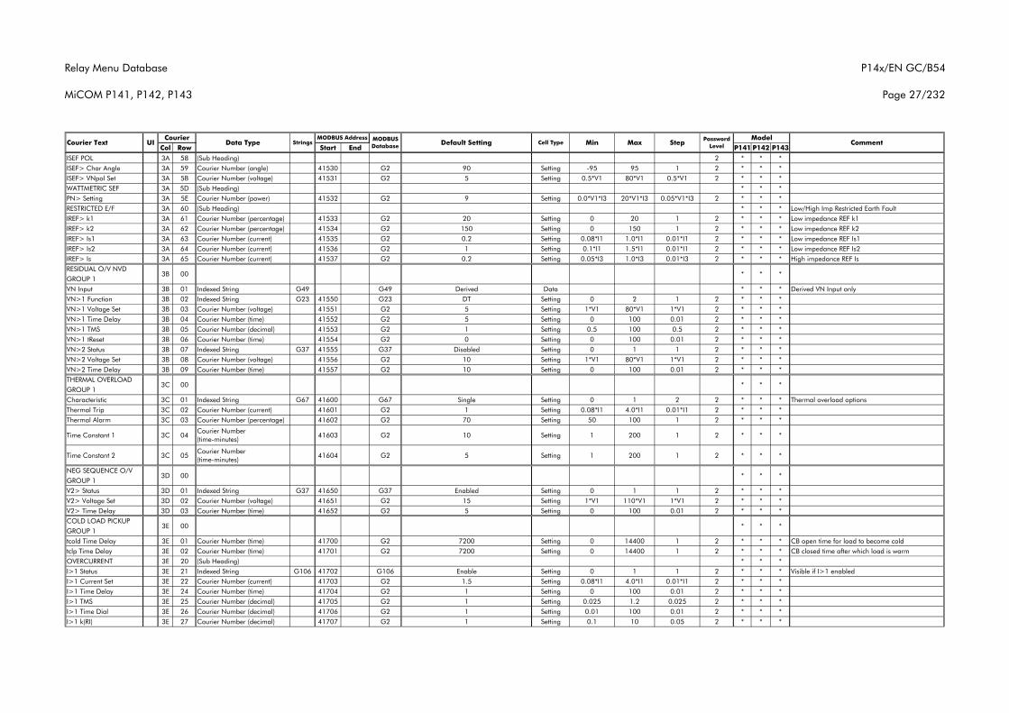
Relay Menu Database
MiCOM P141, P142, P143
P14x/EN GC/B54
Page 27/232
Col Row Start End P141 P142 P143Courier Text UI Data Type Strings
CourierCommentMODBUS
Database Default Setting Cell Type MinMODBUS Address Model
Max Step Password Level
ISEF POL 3A 58 (Sub Heading) 2 * * *ISEF> Char Angle 3A 59 Courier Number (angle) 41530 G2 90 Setting -95 95 1 2 * * *ISEF> VNpol Set 3A 5B Courier Number (voltage) 41531 G2 5 Setting 0.5*V1 80*V1 0.5*V1 2 * * *WATTMETRIC SEF 3A 5D (Sub Heading) * * *PN> Setting 3A 5E Courier Number (power) 41532 G2 9 Setting 0.0*V1*I3 20*V1*I3 0.05*V1*I3 2 * * *RESTRICTED E/F 3A 60 (Sub Heading) * * * Low/High Imp Restricted Earth FaultIREF> k1 3A 61 Courier Number (percentage) 41533 G2 20 Setting 0 20 1 2 * * * Low impedance REF k1IREF> k2 3A 62 Courier Number (percentage) 41534 G2 150 Setting 0 150 1 2 * * * Low impedance REF k2IREF> Is1 3A 63 Courier Number (current) 41535 G2 0.2 Setting 0.08*I1 1.0*I1 0.01*I1 2 * * * Low impedance REF Is1IREF> Is2 3A 64 Courier Number (current) 41536 G2 1 Setting 0.1*I1 1.5*I1 0.01*I1 2 * * * Low impedance REF Is2IREF> Is 3A 65 Courier Number (current) 41537 G2 0.2 Setting 0.05*I3 1.0*I3 0.01*I3 2 * * * High impedance REF IsRESIDUAL O/V NVDGROUP 1VN Input 3B 01 Indexed String G49 G49 Derived Data * * * Derived VN Input onlyVN>1 Function 3B 02 Indexed String G23 41550 G23 DT Setting 0 2 1 2 * * *VN>1 Voltage Set 3B 03 Courier Number (voltage) 41551 G2 5 Setting 1*V1 80*V1 1*V1 2 * * *VN>1 Time Delay 3B 04 Courier Number (time) 41552 G2 5 Setting 0 100 0.01 2 * * *VN>1 TMS 3B 05 Courier Number (decimal) 41553 G2 1 Setting 0.5 100 0.5 2 * * *VN>1 tReset 3B 06 Courier Number (time) 41554 G2 0 Setting 0 100 0.01 2 * * *VN>2 Status 3B 07 Indexed String G37 41555 G37 Disabled Setting 0 1 1 2 * * *VN>2 Voltage Set 3B 08 Courier Number (voltage) 41556 G2 10 Setting 1*V1 80*V1 1*V1 2 * * *VN>2 Time Delay 3B 09 Courier Number (time) 41557 G2 10 Setting 0 100 0.01 2 * * *THERMAL OVERLOADGROUP 1Characteristic 3C 01 Indexed String G67 41600 G67 Single Setting 0 1 2 2 * * * Thermal overload optionsThermal Trip 3C 02 Courier Number (current) 41601 G2 1 Setting 0.08*I1 4.0*I1 0.01*I1 2 * * *Thermal Alarm 3C 03 Courier Number (percentage) 41602 G2 70 Setting 50 100 1 2 * * *
Time Constant 1 3C 04Courier Number (time-minutes)
41603 G2 10 Setting 1 200 1 2 * * *
Time Constant 2 3C 05Courier Number (time-minutes)
41604 G2 5 Setting 1 200 1 2 * * *
NEG SEQUENCE O/VGROUP 1V2> Status 3D 01 Indexed String G37 41650 G37 Enabled Setting 0 1 1 2 * * *V2> Voltage Set 3D 02 Courier Number (voltage) 41651 G2 15 Setting 1*V1 110*V1 1*V1 2 * * *V2> Time Delay 3D 03 Courier Number (time) 41652 G2 5 Setting 0 100 0.01 2 * * *COLD LOAD PICKUPGROUP 1tcold Time Delay 3E 01 Courier Number (time) 41700 G2 7200 Setting 0 14400 1 2 * * * CB open time for load to become coldtclp Time Delay 3E 02 Courier Number (time) 41701 G2 7200 Setting 0 14400 1 2 * * * CB closed time after which load is warmOVERCURRENT 3E 20 (Sub Heading) * * *I>1 Status 3E 21 Indexed String G106 41702 G106 Enable Setting 0 1 1 2 * * * Visible if I>1 enabled I>1 Current Set 3E 22 Courier Number (current) 41703 G2 1.5 Setting 0.08*I1 4.0*I1 0.01*I1 2 * * *I>1 Time Delay 3E 24 Courier Number (time) 41704 G2 1 Setting 0 100 0.01 2 * * *I>1 TMS 3E 25 Courier Number (decimal) 41705 G2 1 Setting 0.025 1.2 0.025 2 * * *I>1 Time Dial 3E 26 Courier Number (decimal) 41706 G2 1 Setting 0.01 100 0.01 2 * * *I>1 k(RI) 3E 27 Courier Number (decimal) 41707 G2 1 Setting 0.1 10 0.05 2 * * *
*3E 00 * *
3D 00 * * *
*
3C 00 * * *
3B 00 * *
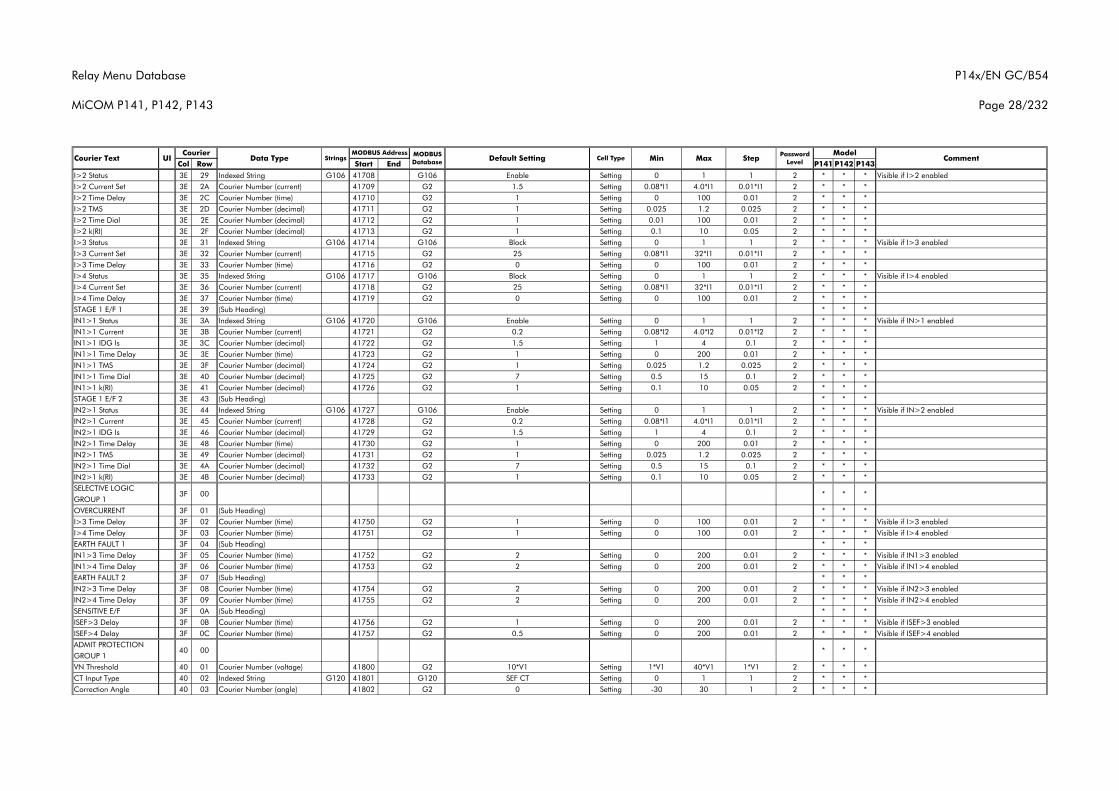
Relay Menu Database
MiCOM P141, P142, P143
P14x/EN GC/B54
Page 28/232
Col Row Start End P141 P142 P143Courier Text UI Data Type Strings
CourierCommentMODBUS
Database Default Setting Cell Type MinMODBUS Address Model
Max Step Password Level
I>2 Status 3E 29 Indexed String G106 41708 G106 Enable Setting 0 1 1 2 * * * Visible if I>2 enabled I>2 Current Set 3E 2A Courier Number (current) 41709 G2 1.5 Setting 0.08*I1 4.0*I1 0.01*I1 2 * * *I>2 Time Delay 3E 2C Courier Number (time) 41710 G2 1 Setting 0 100 0.01 2 * * *I>2 TMS 3E 2D Courier Number (decimal) 41711 G2 1 Setting 0.025 1.2 0.025 2 * * *I>2 Time Dial 3E 2E Courier Number (decimal) 41712 G2 1 Setting 0.01 100 0.01 2 * * *I>2 k(RI) 3E 2F Courier Number (decimal) 41713 G2 1 Setting 0.1 10 0.05 2 * * *I>3 Status 3E 31 Indexed String G106 41714 G106 Block Setting 0 1 1 2 * * * Visible if I>3 enabled I>3 Current Set 3E 32 Courier Number (current) 41715 G2 25 Setting 0.08*I1 32*I1 0.01*I1 2 * * *I>3 Time Delay 3E 33 Courier Number (time) 41716 G2 0 Setting 0 100 0.01 2 * * *I>4 Status 3E 35 Indexed String G106 41717 G106 Block Setting 0 1 1 2 * * * Visible if I>4 enabled I>4 Current Set 3E 36 Courier Number (current) 41718 G2 25 Setting 0.08*I1 32*I1 0.01*I1 2 * * *I>4 Time Delay 3E 37 Courier Number (time) 41719 G2 0 Setting 0 100 0.01 2 * * *STAGE 1 E/F 1 3E 39 (Sub Heading) * * *IN1>1 Status 3E 3A Indexed String G106 41720 G106 Enable Setting 0 1 1 2 * * * Visible if IN>1 enabled IN1>1 Current 3E 3B Courier Number (current) 41721 G2 0.2 Setting 0.08*I2 4.0*I2 0.01*I2 2 * * *IN1>1 IDG Is 3E 3C Courier Number (decimal) 41722 G2 1.5 Setting 1 4 0.1 2 * * *IN1>1 Time Delay 3E 3E Courier Number (time) 41723 G2 1 Setting 0 200 0.01 2 * * *IN1>1 TMS 3E 3F Courier Number (decimal) 41724 G2 1 Setting 0.025 1.2 0.025 2 * * *IN1>1 Time Dial 3E 40 Courier Number (decimal) 41725 G2 7 Setting 0.5 15 0.1 2 * * *IN1>1 k(RI) 3E 41 Courier Number (decimal) 41726 G2 1 Setting 0.1 10 0.05 2 * * *STAGE 1 E/F 2 3E 43 (Sub Heading) * * *IN2>1 Status 3E 44 Indexed String G106 41727 G106 Enable Setting 0 1 1 2 * * * Visible if IN>2 enabled IN2>1 Current 3E 45 Courier Number (current) 41728 G2 0.2 Setting 0.08*I1 4.0*I1 0.01*I1 2 * * *IN2>1 IDG Is 3E 46 Courier Number (decimal) 41729 G2 1.5 Setting 1 4 0.1 2 * * *IN2>1 Time Delay 3E 48 Courier Number (time) 41730 G2 1 Setting 0 200 0.01 2 * * *IN2>1 TMS 3E 49 Courier Number (decimal) 41731 G2 1 Setting 0.025 1.2 0.025 2 * * *IN2>1 Time Dial 3E 4A Courier Number (decimal) 41732 G2 7 Setting 0.5 15 0.1 2 * * *IN2>1 k(RI) 3E 4B Courier Number (decimal) 41733 G2 1 Setting 0.1 10 0.05 2 * * *SELECTIVE LOGICGROUP 1OVERCURRENT 3F 01 (Sub Heading) * * *I>3 Time Delay 3F 02 Courier Number (time) 41750 G2 1 Setting 0 100 0.01 2 * * * Visible if I>3 enabledI>4 Time Delay 3F 03 Courier Number (time) 41751 G2 1 Setting 0 100 0.01 2 * * * Visible if I>4 enabledEARTH FAULT 1 3F 04 (Sub Heading) * * *IN1>3 Time Delay 3F 05 Courier Number (time) 41752 G2 2 Setting 0 200 0.01 2 * * * Visible if IN1>3 enabledIN1>4 Time Delay 3F 06 Courier Number (time) 41753 G2 2 Setting 0 200 0.01 2 * * * Visible if IN1>4 enabledEARTH FAULT 2 3F 07 (Sub Heading) * * *IN2>3 Time Delay 3F 08 Courier Number (time) 41754 G2 2 Setting 0 200 0.01 2 * * * Visible if IN2>3 enabledIN2>4 Time Delay 3F 09 Courier Number (time) 41755 G2 2 Setting 0 200 0.01 2 * * * Visible if IN2>4 enabledSENSITIVE E/F 3F 0A (Sub Heading) * * *ISEF>3 Delay 3F 0B Courier Number (time) 41756 G2 1 Setting 0 200 0.01 2 * * * Visible if ISEF>3 enabledISEF>4 Delay 3F 0C Courier Number (time) 41757 G2 0.5 Setting 0 200 0.01 2 * * * Visible if ISEF>4 enabledADMIT PROTECTIONGROUP 1VN Threshold 40 01 Courier Number (voltage) 41800 G2 10*V1 Setting 1*V1 40*V1 1*V1 2 * * *CT Input Type 40 02 Indexed String G120 41801 G120 SEF CT Setting 0 1 1 2 * * *Correction Angle 40 03 Courier Number (angle) 41802 G2 0 Setting -30 30 1 2 * * *
*
40 00 * * *
3F 00 * *
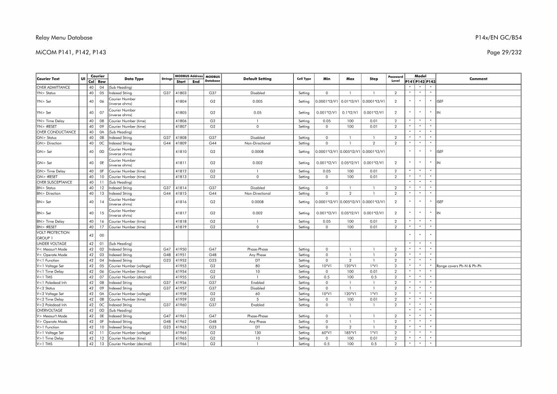
Relay Menu Database
MiCOM P141, P142, P143
P14x/EN GC/B54
Page 29/232
Col Row Start End P141 P142 P143Courier Text UI Data Type Strings
CourierCommentMODBUS
Database Default Setting Cell Type MinMODBUS Address Model
Max Step Password Level
OVER ADMITTANCE 40 04 (Sub Heading) * * *YN> Status 40 05 Indexed String G37 41803 G37 Disabled Setting 0 1 1 2 * * *
YN> Set 40 06Courier Number (inverse ohms)
41804 G2 0.005 Setting 0.0001*I3/V1 0.01*I3/V1 0.0001*I3/V1 2 * * * ISEF
YN> Set 40 07Courier Number (inverse ohms)
41805 G2 0.05 Setting 0.001*I2/V1 0.1*I2/V1 0.001*I2/V1 2 * * * IN
YN> Time Delay 40 08 Courier Number (time) 41806 G2 1 Setting 0.05 100 0.01 2 * * *YN> tRESET 40 09 Courier Number (time) 41807 G2 0 Setting 0 100 0.01 2 * * *OVER CONDUCTANCE 40 0A (Sub Heading) * * *GN> Status 40 0B Indexed String G37 41808 G37 Disabled Setting 0 1 1 2 * * *GN> Direction 40 0C Indexed String G44 41809 G44 Non-Directional Setting 0 1 2 2 * * *
GN> Set 40 0DCourier Number (inverse ohms)
41810 G2 0.0008 Setting 0.0001*I3/V1 0.005*I3/V1 0.0001*I3/V1 * * * ISEF
GN> Set 40 0ECourier Number (inverse ohms)
41811 G2 0.002 Setting 0.001*I2/V1 0.05*I2/V1 0.001*I2/V1 2 * * * IN
GN> Time Delay 40 0F Courier Number (time) 41812 G2 1 Setting 0.05 100 0.01 2 * * *GN> tRESET 40 10 Courier Number (time) 41813 G2 0 Setting 0 100 0.01 2 * * *OVER SUSCEPTANCE 40 11 (Sub Heading) * * *BN> Status 40 12 Indexed String G37 41814 G37 Disabled Setting 0 1 1 2 * * *BN> Direction 40 13 Indexed String G44 41815 G44 Non-Directional Setting 0 2 1 2 * * *
BN> Set 40 14Courier Number (inverse ohms)
41816 G2 0.0008 Setting 0.0001*I3/V1 0.005*I3/V1 0.0001*I3/V1 2 * * * ISEF
BN> Set 40 15Courier Number (inverse ohms)
41817 G2 0.002 Setting 0.001*I2/V1 0.05*I2/V1 0.001*I2/V1 2 * * * IN
BN> Time Delay 40 16 Courier Number (time) 41818 G2 1 Setting 0.05 100 0.01 2 * * *BN> tRESET 40 17 Courier Number (time) 41819 G2 0 Setting 0 100 0.01 2 * * *VOLT PROTECTIONGROUP 1UNDER VOLTAGE 42 01 (Sub Heading) * * *V< Measur't Mode 42 02 Indexed String G47 41950 G47 Phase-Phase Setting 0 1 1 2 * * *V< Operate Mode 42 03 Indexed String G48 41951 G48 Any Phase Setting 0 1 1 2 * * *V<1 Function 42 04 Indexed String G23 41952 G23 DT Setting 0 2 1 2 * * *V<1 Voltage Set 42 05 Courier Number (voltage) 41953 G2 80 Setting 10*V1 120*V1 1*V1 2 * * * Range covers Ph-N & Ph-PhV<1 Time Delay 42 06 Courier Number (time) 41954 G2 10 Setting 0 100 0.01 2 * * *V<1 TMS 42 07 Courier Number (decimal) 41955 G2 1 Setting 0.5 100 0.5 2 * * *V<1 Poledead Inh 42 08 Indexed String G37 41956 G37 Enabled Setting 0 1 1 2 * * *V<2 Status 42 09 Indexed String G37 41957 G37 Disabled Setting 0 1 1 2 * * *V<2 Voltage Set 42 0A Courier Number (voltage) 41958 G2 60 Setting 10*V1 120*V1 1*V1 2 * * *V<2 Time Delay 42 0B Courier Number (time) 41959 G2 5 Setting 0 100 0.01 2 * * *V<2 Poledead Inh 42 0C Indexed String G37 41960 G37 Enabled Setting 0 1 1 2 * * *OVERVOLTAGE 42 0D (Sub Heading) * * *V> Measur't Mode 42 0E Indexed String G47 41961 G47 Phase-Phase Setting 0 1 1 2 * * *V> Operate Mode 42 0F Indexed String G48 41962 G48 Any Phase Setting 0 1 1 2 * * *V>1 Function 42 10 Indexed String G23 41963 G23 DT Setting 0 2 1 2 * * *V>1 Voltage Set 42 11 Courier Number (voltage) 41964 G2 130 Setting 60*V1 185*V1 1*V1 2 * * *V>1 Time Delay 42 12 Courier Number (time) 41965 G2 10 Setting 0 100 0.01 2 * * *V>1 TMS 42 13 Courier Number (decimal) 41966 G2 1 Setting 0.5 100 0.5 2 * * *
*42 00 * *
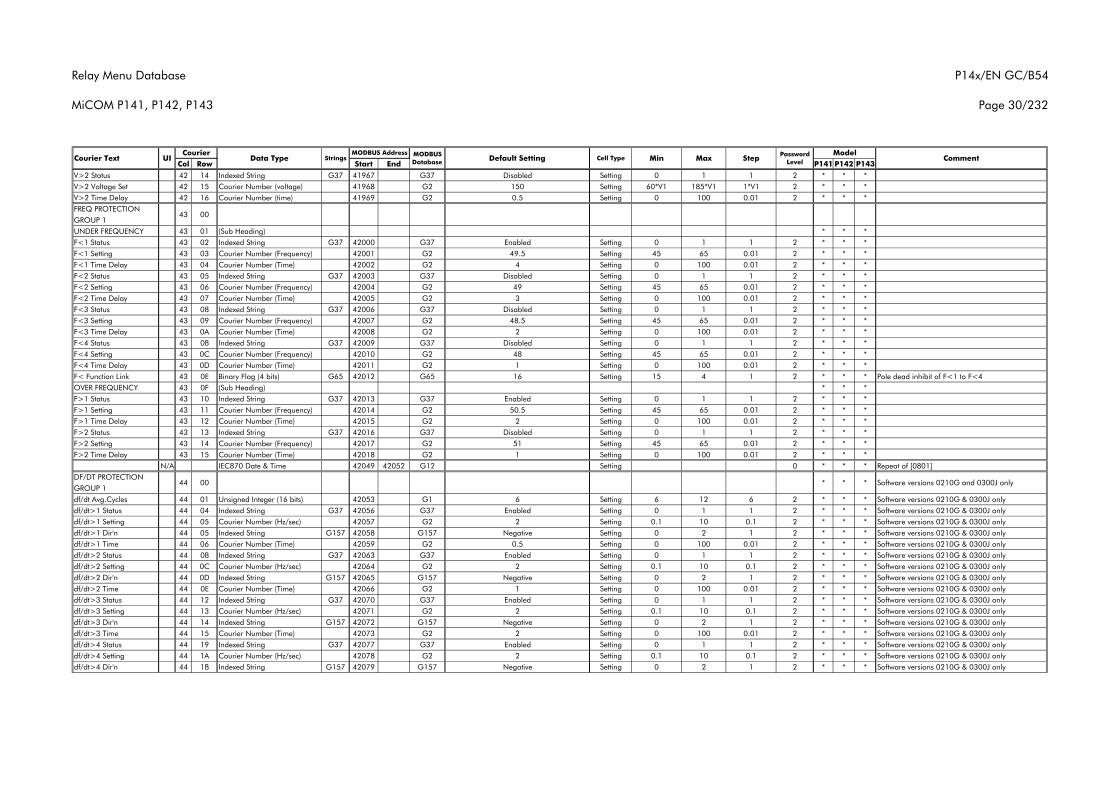
Relay Menu Database
MiCOM P141, P142, P143
P14x/EN GC/B54
Page 30/232
Col Row Start End P141 P142 P143Courier Text UI Data Type Strings
CourierCommentMODBUS
Database Default Setting Cell Type MinMODBUS Address Model
Max Step Password Level
V>2 Status 42 14 Indexed String G37 41967 G37 Disabled Setting 0 1 1 2 * * *V>2 Voltage Set 42 15 Courier Number (voltage) 41968 G2 150 Setting 60*V1 185*V1 1*V1 2 * * *V>2 Time Delay 42 16 Courier Number (time) 41969 G2 0.5 Setting 0 100 0.01 2 * * *FREQ PROTECTIONGROUP 1UNDER FREQUENCY 43 01 (Sub Heading) * * *F<1 Status 43 02 Indexed String G37 42000 G37 Enabled Setting 0 1 1 2 * * *F<1 Setting 43 03 Courier Number (Frequency) 42001 G2 49.5 Setting 45 65 0.01 2 * * *F<1 Time Delay 43 04 Courier Number (Time) 42002 G2 4 Setting 0 100 0.01 2 * * *F<2 Status 43 05 Indexed String G37 42003 G37 Disabled Setting 0 1 1 2 * * *F<2 Setting 43 06 Courier Number (Frequency) 42004 G2 49 Setting 45 65 0.01 2 * * *F<2 Time Delay 43 07 Courier Number (Time) 42005 G2 3 Setting 0 100 0.01 2 * * *F<3 Status 43 08 Indexed String G37 42006 G37 Disabled Setting 0 1 1 2 * * *F<3 Setting 43 09 Courier Number (Frequency) 42007 G2 48.5 Setting 45 65 0.01 2 * * *F<3 Time Delay 43 0A Courier Number (Time) 42008 G2 2 Setting 0 100 0.01 2 * * *F<4 Status 43 0B Indexed String G37 42009 G37 Disabled Setting 0 1 1 2 * * *F<4 Setting 43 0C Courier Number (Frequency) 42010 G2 48 Setting 45 65 0.01 2 * * *F<4 Time Delay 43 0D Courier Number (Time) 42011 G2 1 Setting 0 100 0.01 2 * * *F< Function Link 43 0E Binary Flag (4 bits) G65 42012 G65 16 Setting 15 4 1 2 * * * Pole dead inhibit of F<1 to F<4OVER FREQUENCY 43 0F (Sub Heading) * * *F>1 Status 43 10 Indexed String G37 42013 G37 Enabled Setting 0 1 1 2 * * *F>1 Setting 43 11 Courier Number (Frequency) 42014 G2 50.5 Setting 45 65 0.01 2 * * *F>1 Time Delay 43 12 Courier Number (Time) 42015 G2 2 Setting 0 100 0.01 2 * * *F>2 Status 43 13 Indexed String G37 42016 G37 Disabled Setting 0 1 1 2 * * *F>2 Setting 43 14 Courier Number (Frequency) 42017 G2 51 Setting 45 65 0.01 2 * * *F>2 Time Delay 43 15 Courier Number (Time) 42018 G2 1 Setting 0 100 0.01 2 * * *
N/A IEC870 Date & Time 42049 42052 G12 Setting 0 * * * Repeat of [0801]DF/DT PROTECTIONGROUP 1df/dt Avg.Cycles 44 01 Unsigned Integer (16 bits) 42053 G1 6 Setting 6 12 6 2 * * * Software versions 0210G & 0300J onlydf/dt>1 Status 44 04 Indexed String G37 42056 G37 Enabled Setting 0 1 1 2 * * * Software versions 0210G & 0300J onlydf/dt>1 Setting 44 05 Courier Number (Hz/sec) 42057 G2 2 Setting 0.1 10 0.1 2 * * * Software versions 0210G & 0300J onlydf/dt>1 Dir'n 44 05 Indexed String G157 42058 G157 Negative Setting 0 2 1 2 * * * Software versions 0210G & 0300J onlydf/dt>1 Time 44 06 Courier Number (Time) 42059 G2 0.5 Setting 0 100 0.01 2 * * * Software versions 0210G & 0300J onlydf/dt>2 Status 44 0B Indexed String G37 42063 G37 Enabled Setting 0 1 1 2 * * * Software versions 0210G & 0300J onlydf/dt>2 Setting 44 0C Courier Number (Hz/sec) 42064 G2 2 Setting 0.1 10 0.1 2 * * * Software versions 0210G & 0300J onlydf/dt>2 Dir'n 44 0D Indexed String G157 42065 G157 Negative Setting 0 2 1 2 * * * Software versions 0210G & 0300J onlydf/dt>2 Time 44 0E Courier Number (Time) 42066 G2 1 Setting 0 100 0.01 2 * * * Software versions 0210G & 0300J onlydf/dt>3 Status 44 12 Indexed String G37 42070 G37 Enabled Setting 0 1 1 2 * * * Software versions 0210G & 0300J onlydf/dt>3 Setting 44 13 Courier Number (Hz/sec) 42071 G2 2 Setting 0.1 10 0.1 2 * * * Software versions 0210G & 0300J onlydf/dt>3 Dir'n 44 14 Indexed String G157 42072 G157 Negative Setting 0 2 1 2 * * * Software versions 0210G & 0300J onlydf/dt>3 Time 44 15 Courier Number (Time) 42073 G2 2 Setting 0 100 0.01 2 * * * Software versions 0210G & 0300J onlydf/dt>4 Status 44 19 Indexed String G37 42077 G37 Enabled Setting 0 1 1 2 * * * Software versions 0210G & 0300J onlydf/dt>4 Setting 44 1A Courier Number (Hz/sec) 42078 G2 2 Setting 0.1 10 0.1 2 * * * Software versions 0210G & 0300J onlydf/dt>4 Dir'n 44 1B Indexed String G157 42079 G157 Negative Setting 0 2 1 2 * * * Software versions 0210G & 0300J only
43 00
44 00 * * Software versions 0210G and 0300J only*
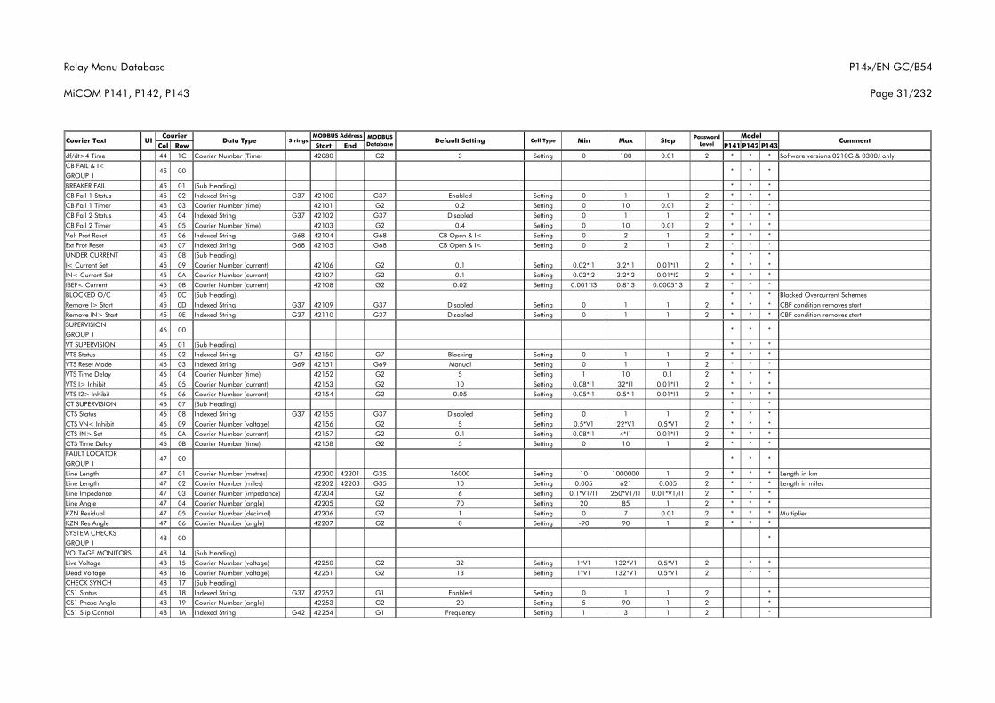
Relay Menu Database
MiCOM P141, P142, P143
P14x/EN GC/B54
Page 31/232
Col Row Start End P141 P142 P143Courier Text UI Data Type Strings
CourierCommentMODBUS
Database Default Setting Cell Type MinMODBUS Address Model
Max Step Password Level
df/dt>4 Time 44 1C Courier Number (Time) 42080 G2 3 Setting 0 100 0.01 2 * * * Software versions 0210G & 0300J onlyCB FAIL & I<GROUP 1BREAKER FAIL 45 01 (Sub Heading) * * *CB Fail 1 Status 45 02 Indexed String G37 42100 G37 Enabled Setting 0 1 1 2 * * *CB Fail 1 Timer 45 03 Courier Number (time) 42101 G2 0.2 Setting 0 10 0.01 2 * * *CB Fail 2 Status 45 04 Indexed String G37 42102 G37 Disabled Setting 0 1 1 2 * * *CB Fail 2 Timer 45 05 Courier Number (time) 42103 G2 0.4 Setting 0 10 0.01 2 * * *Volt Prot Reset 45 06 Indexed String G68 42104 G68 CB Open & I< Setting 0 2 1 2 * * *Ext Prot Reset 45 07 Indexed String G68 42105 G68 CB Open & I< Setting 0 2 1 2 * * *UNDER CURRENT 45 08 (Sub Heading) * * *I< Current Set 45 09 Courier Number (current) 42106 G2 0.1 Setting 0.02*I1 3.2*I1 0.01*I1 2 * * *IN< Current Set 45 0A Courier Number (current) 42107 G2 0.1 Setting 0.02*I2 3.2*I2 0.01*I2 2 * * *ISEF< Current 45 0B Courier Number (current) 42108 G2 0.02 Setting 0.001*I3 0.8*I3 0.0005*I3 2 * * *BLOCKED O/C 45 0C (Sub Heading) * * * Blocked Overcurrent SchemesRemove I> Start 45 0D Indexed String G37 42109 G37 Disabled Setting 0 1 1 2 * * * CBF condition removes startRemove IN> Start 45 0E Indexed String G37 42110 G37 Disabled Setting 0 1 1 2 * * * CBF condition removes startSUPERVISIONGROUP 1VT SUPERVISION 46 01 (Sub Heading) * * *VTS Status 46 02 Indexed String G7 42150 G7 Blocking Setting 0 1 1 2 * * *VTS Reset Mode 46 03 Indexed String G69 42151 G69 Manual Setting 0 1 1 2 * * *VTS Time Delay 46 04 Courier Number (time) 42152 G2 5 Setting 1 10 0.1 2 * * *VTS I> Inhibit 46 05 Courier Number (current) 42153 G2 10 Setting 0.08*I1 32*I1 0.01*I1 2 * * *VTS I2> Inhibit 46 06 Courier Number (current) 42154 G2 0.05 Setting 0.05*I1 0.5*I1 0.01*I1 2 * * *CT SUPERVISION 46 07 (Sub Heading) * * *CTS Status 46 08 Indexed String G37 42155 G37 Disabled Setting 0 1 1 2 * * *CTS VN< Inhibit 46 09 Courier Number (voltage) 42156 G2 5 Setting 0.5*V1 22*V1 0.5*V1 2 * * *CTS IN> Set 46 0A Courier Number (current) 42157 G2 0.1 Setting 0.08*I1 4*I1 0.01*I1 2 * * *CTS Time Delay 46 0B Courier Number (time) 42158 G2 5 Setting 0 10 1 2 * * *FAULT LOCATORGROUP 1Line Length 47 01 Courier Number (metres) 42200 42201 G35 16000 Setting 10 1000000 1 2 * * * Length in kmLine Length 47 02 Courier Number (miles) 42202 42203 G35 10 Setting 0.005 621 0.005 2 * * * Length in milesLine Impedance 47 03 Courier Number (impedance) 42204 G2 6 Setting 0.1*V1/I1 250*V1/I1 0.01*V1/I1 2 * * *Line Angle 47 04 Courier Number (angle) 42205 G2 70 Setting 20 85 1 2 * * *KZN Residual 47 05 Courier Number (decimal) 42206 G2 1 Setting 0 7 0.01 2 * * * MultiplierKZN Res Angle 47 06 Courier Number (angle) 42207 G2 0 Setting -90 90 1 2 * * *SYSTEM CHECKSGROUP 1VOLTAGE MONITORS 48 14 (Sub Heading)Live Voltage 48 15 Courier Number (voltage) 42250 G2 32 Setting 1*V1 132*V1 0.5*V1 2 * *Dead Voltage 48 16 Courier Number (voltage) 42251 G2 13 Setting 1*V1 132*V1 0.5*V1 2 * *CHECK SYNCH 48 17 (Sub Heading)CS1 Status 48 18 Indexed String G37 42252 G1 Enabled Setting 0 1 1 2 *CS1 Phase Angle 48 19 Courier Number (angle) 42253 G2 20 Setting 5 90 1 2 *CS1 Slip Control 48 1A Indexed String G42 42254 G1 Frequency Setting 1 3 1 2 *
*
45 00 * *
46 00 * *
47 00 * *
48 00
*
*
*
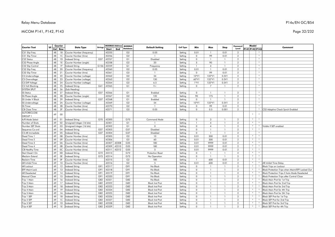
Relay Menu Database
MiCOM P141, P142, P143
P14x/EN GC/B54
Page 32/232
Col Row Start End P141 P142 P143Courier Text UI Data Type Strings
CourierCommentMODBUS
Database Default Setting Cell Type MinMODBUS Address Model
Max Step Password Level
CS1 Slip Freq 48 1B Courier Number (frequency) 42255 G2 0.05 Setting 0.01 1 0.01 2 *CS1 Slip Timer 48 1C Courier Number (time) 42256 G2 1 Setting 0 99 0.01 2 *CS2 Status 48 1D Indexed String G37 42257 G1 Disabled Setting 0 1 1 2 *CS2 Phase Angle 48 1E Courier Number (angle) 42258 G2 20 Setting 5 90 1 2 *CS2 Slip Control 48 1F Indexed String G156 42259 G1 Frequency Setting 1 4 1 2 *CS2 Slip Freq 48 20 Courier Number (frequency) 42260 G2 0.05 Setting 0.01 1 0.01 2 *CS2 Slip Timer 48 21 Courier Number (time) 42261 G2 1 Setting 0 99 0.01 2 *CS Undervoltage 48 22 Courier Number (voltage) 42262 G2 54 Setting 10*V1 132*V1 0.5V1 2 *CS Overvoltage 48 23 Courier Number (voltage) 42263 G2 130 Setting 60*V1 132*V1 0.5V1 2 *CS Diff Voltage 48 24 Courier Number (voltage) 42264 G2 6.5 Setting 1*V1 132*V1 0.5V1 2 *CS Volt Blocking 48 25 Indexed String G41 42265 G1 V< Setting 0 7 1 2 *SYSTEM SPLIT 48 26 (Sub Heading)SS Status 48 27 Indexed String G37 42266 G1 Enabled Setting 0 1 1 2 *SS Phase Angle 48 28 Courier Number (angle) 42267 G2 120 Setting 90 175 1 2 *SS Under V Block 48 29 Indexed String G37 42268 G1 Enabled Setting 0 1 1 2 *SS Undervoltage 48 2A Courier Number (voltage) 42269 G2 54 Setting 10*V1 132*V1 0.5V1 2 *SS Timer 48 2B Courier Number (time) 42270 G2 1 Setting 0 99 0.01 2 *CB Close Time 48 2F Courier Number (time) 42271 G2 0.05 Setting 0 0.5 0.001 2 * CS2 Adaptive Check Synch EnabledAUTORECLOSEGROUP 1A/R Mode Select 49 01 Indexed String G70 42300 G70 Command Mode Setting 0 3 1 2 * *Number of Shots 49 02 Unsigned Integer (16 bits) 42301 G1 1 Setting 1 4 1 2 * *Number SEF Shots 49 03 Unsigned Integer (16 bits) 42302 G1 0 Setting 0 4 1 2 * * Visible if SEF enabledSequence Co-ord 49 04 Indexed String G37 42303 G37 Disabled Setting 0 1 1 2 * *CS AR Immediate 49 05 Indexed String G37 42304 G37 Disabled Setting 0 1 1 2 *Dead Time 1 49 08 Courier Number (time) 42305 G2 10 Setting 0.01 300 0.01 2 * *Dead Time 2 49 09 Courier Number (time) 42306 G2 60 Setting 0.01 300 0.01 2 * *Dead Time 3 49 0A Courier Number (time) 42307 42308 G35 180 Setting 0.01 9999 0.01 2 * *Dead Time 4 49 0B Courier Number (time) 42309 42310 G35 180 Setting 0.01 9999 0.01 2 * *CB Healthy Time 49 0C Courier Number (time) 42311 42312 G35 5 Setting 0.01 9999 0.01 2 * *Start Dead t On 49 0D Indexed String G72 42313 G72 Protection Reset Setting 0 1 1 2 * *tReclaim Extend 49 0E Indexed String G73 42314 G73 No Operation Setting 0 1 1 2 * *Reclaim Time 49 0F Courier Number (time) 42315 G2 180 Setting 1 600 0.01 2 * *AR Inhibit Time 49 10 Courier Number (time) 42316 G2 5 Setting 0.01 600 0.01 2 * * AR Inhibit Time DelayAR Lockout 49 12 Indexed String G91 42317 G91 No Block Setting 0 1 1 2 * * Block Trips on LockoutEFF Maint Lock 49 13 Indexed String G91 42318 G91 No Block Setting 0 1 1 2 * * Block Protection Trips when Maint/EFF Locked OutAR Deselected 49 14 Indexed String G91 42319 G91 No Block Setting 0 1 1 2 * * Block Protection Trips if Auto Mode DeselectedManual Close 49 15 Indexed String G91 42320 G91 No Block Setting 0 1 1 2 * * Block Protection Trips after Control CloseTrip 1 Main 49 16 Indexed String G82 42321 G82 No Block Setting 0 1 1 2 * * Block Main Prot for 1st TripTrip 2 Main 49 17 Indexed String G82 42322 G82 Block Inst Prot Setting 0 1 1 2 * * Block Main Prot for 2nd TripTrip 3 Main 49 18 Indexed String G82 42323 G82 Block Inst Prot Setting 0 1 1 2 * * Block Main Prot for 3rd TripTrip 4 Main 49 19 Indexed String G82 42324 G82 Block Inst Prot Setting 0 1 1 2 * * Block Main Prot for 4th TripTrip 5 Main 49 1A Indexed String G82 42325 G82 Block Inst Prot Setting 0 1 1 2 * * Block Main Prot for 5th TripTrip 1 SEF 49 1B Indexed String G82 42326 G82 Block Inst Prot Setting 0 1 1 2 * * Block SEF Prot for 1st TripTrip 2 SEF 49 1C Indexed String G82 42327 G82 Block Inst Prot Setting 0 1 1 2 * * Block SEF Prot for 2nd TripTrip 3 SEF 49 1D Indexed String G82 42328 G82 Block Inst Prot Setting 0 1 1 2 * * Block SEF Prot for 3rd TripTrip 4 SEF 49 1E Indexed String G82 42329 G82 Block Inst Prot Setting 0 1 1 2 * * Block SEF Prot for 4th Trip
49 00 * *
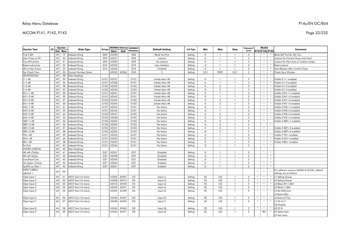
Relay Menu Database
MiCOM P141, P142, P143
P14x/EN GC/B54
Page 33/232
Col Row Start End P141 P142 P143Courier Text UI Data Type Strings
CourierCommentMODBUS
Database Default Setting Cell Type MinMODBUS Address Model
Max Step Password Level
Trip 5 SEF 49 1F Indexed String G82 42330 G82 Block Inst Prot Setting 0 1 1 2 * * Block SEF Prot for 5th TripMan Close on Flt 49 20 Indexed String G92 42331 G92 Lockout Setting 0 1 1 2 * * Lockout for Control Close onto FaultTrip AR Inactive 49 21 Indexed String G92 42332 G92 No Lockout Setting 0 1 1 2 * * Lockout for Non Auto or Liveline modesReset Lockout by 49 22 Indexed String G74 42333 G74 User Interface Setting 0 1 1 2 * * Reset LockoutAR on Man Close 49 24 Indexed String G75 42334 G75 Inhibited Setting 0 1 1 2 * * Auto-Reclose after Control CloseSys Check Time 49 25 Courier Number (time) 42335 42336 G35 5 Setting 0.01 9999 0.01 2 * * Check Sync WindowAR INITIATION 49 28 (Sub Heading) * *I>1 AR 49 29 Indexed String G101 42337 G101 Initiate Main AR Setting 0 1 1 2 * * Visible if I>1 enabledI>2 AR 49 2A Indexed String G101 42338 G101 Initiate Main AR Setting 0 1 1 2 * * Visible if I>2 enabledI>3 AR 49 2B Indexed String G102 42339 G102 Initiate Main AR Setting 0 2 1 2 * * Visible if I>3 enabledI>4 AR 49 2C Indexed String G102 42340 G102 Initiate Main AR Setting 0 2 1 2 * * Visible if I>4 enabledIN1>1 AR 49 2D Indexed String G101 42341 G101 Initiate Main AR Setting 0 1 1 2 * * Visible if IN1>1 enabledIN1>2 AR 49 2E Indexed String G101 42342 G101 Initiate Main AR Setting 0 1 1 2 * * Visible if IN1>2 enabledIN1>3 AR 49 2F Indexed String G102 42343 G102 Initiate Main AR Setting 0 2 1 2 * * Visible if IN1>3 enabledIN1>4 AR 49 30 Indexed String G102 42344 G102 Initiate Main AR Setting 0 2 1 2 * * Visible if IN1>4 enabledIN2>1 AR 49 31 Indexed String G101 42345 G101 No Action Setting 0 1 1 2 * * Visible if IN2>1 enabledIN2>2 AR 49 32 Indexed String G101 42346 G101 No Action Setting 0 1 1 2 * * Visible if IN2>2 enabledIN2>3 AR 49 33 Indexed String G102 42347 G102 No Action Setting 0 2 1 2 * * Visible if IN2>3 enabledIN2>4 AR 49 34 Indexed String G102 42348 G102 No Action Setting 0 2 1 2 * * Visible if IN2>4 enabledISEF>1 AR 49 35 Indexed String G103 42349 G103 No Action Setting 0 2 1 2 * Visible if ISEF>1 enabledISEF>2 AR 49 36 Indexed String G103 42350 G103 No Action Setting 0 3 1 2 *ISEF>3 AR 49 37 Indexed String G103 42351 G103 No Action Setting 0 2 1 2 * Visible if ISEF>3 enabledISEF>4 AR 49 38 Indexed String G103 42352 G103 No Action Setting 0 2 1 2 * Visible if ISEF>4 enabledYN> AR 49 39 Indexed String G101 42353 G101 No Action Setting 0 1 1 2 * * Visible if YN> enabledGN> AR 49 3A Indexed String G101 42354 G101 No Action Setting 0 1 1 2 * * Visible if GN> enabledBN> AR 49 3B Indexed String G101 42355 G101 No Action Setting 0 1 1 2 * * Visible if BN> enabledExt Prot 49 3C Indexed String G101 42356 G101 No Action Setting 0 1 1 2 * *SYSTEM CHECKS 49 40 (Sub Heading)AR with ChkSyn 49 41 Indexed String G37 42357 G37 Disabled Setting 0 1 1 2 * *AR with SysSyn 49 42 Indexed String G37 42358 G37 Disabled Setting 0 1 1 2 *Live/Dead Ccts 49 43 Indexed String G37 42359 G37 Disabled Setting 0 1 1 2 *No System Checks 49 44 Indexed String G37 42360 G37 Enabled Setting 0 1 1 2 * *SysChk on Shot 1 49 45 Indexed String G37 42361 G37 Enabled Setting 0 1 1 2 * *INPUT LABELSGROUP 1Opto Input 1 4A 01 ASCII Text (16 chars) 42400 42407 G3 Input L1 Setting 32 163 1 2 * * * L1 Setting GroupOpto Input 2 4A 02 ASCII Text (16 chars) 42408 42415 G3 Input L2 Setting 32 163 1 2 * * * L2 Setting GroupOpto Input 3 4A 03 ASCII Text (16 chars) 42416 42423 G3 Input L3 Setting 32 163 1 2 * * * L3 Block IN1>3&4Opto Input 4 4A 04 ASCII Text (16 chars) 42424 42431 G3 Input L4 Setting 32 163 1 2 * * * L4 Block I>3&4Opto Input 5 4A 05 ASCII Text (16 chars) 42432 42439 G3 Input L5 Setting 32 163 1 2 * * * L5 Rst LEDs/Lckt
L5 Reset LEDsOpto Input 6 4A 06 ASCII Text (16 chars) 42440 42447 G3 Input L6 Setting 32 163 1 2 * * * L6 External TripOpto Input 7 4A 07 ASCII Text (16 chars) 42448 42455 G3 Input L7 Setting 32 163 1 2 * * * L7 52-A L7
CB HealthyOpto Input 8 4A 08 ASCII Text (16 chars) 42456 42463 G3 Input L8 Setting 32 163 1 2 * * * L8 52-BOpto Input 9 4A 09 ASCII Text (16 chars) 42464 42471 G3 Input L9 Setting 32 163 1 2 *BC * L9 Select Auto
L9 Not Used
4A 00 * * *For software versions 0200G & 0210G, default settings are as follows:
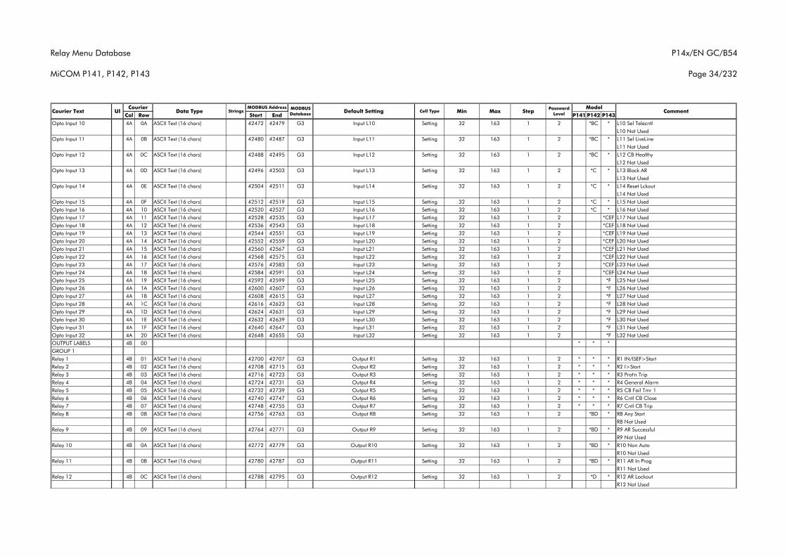
Relay Menu Database
MiCOM P141, P142, P143
P14x/EN GC/B54
Page 34/232
Col Row Start End P141 P142 P143Courier Text UI Data Type Strings
CourierCommentMODBUS
Database Default Setting Cell Type MinMODBUS Address Model
Max Step Password Level
Opto Input 10 4A 0A ASCII Text (16 chars) 42472 42479 G3 Input L10 Setting 32 163 1 2 *BC * L10 Sel TelecntlL10 Not Used
Opto Input 11 4A 0B ASCII Text (16 chars) 42480 42487 G3 Input L11 Setting 32 163 1 2 *BC * L11 Sel LiveLineL11 Not Used
Opto Input 12 4A 0C ASCII Text (16 chars) 42488 42495 G3 Input L12 Setting 32 163 1 2 *BC * L12 CB HealthyL12 Not Used
Opto Input 13 4A 0D ASCII Text (16 chars) 42496 42503 G3 Input L13 Setting 32 163 1 2 *C * L13 Block ARL13 Not Used
Opto Input 14 4A 0E ASCII Text (16 chars) 42504 42511 G3 Input L14 Setting 32 163 1 2 *C * L14 Reset LckoutL14 Not Used
Opto Input 15 4A 0F ASCII Text (16 chars) 42512 42519 G3 Input L15 Setting 32 163 1 2 *C * L15 Not UsedOpto Input 16 4A 10 ASCII Text (16 chars) 42520 42527 G3 Input L16 Setting 32 163 1 2 *C * L16 Not UsedOpto Input 17 4A 11 ASCII Text (16 chars) 42528 42535 G3 Input L17 Setting 32 163 1 2 *CEF L17 Not UsedOpto Input 18 4A 12 ASCII Text (16 chars) 42536 42543 G3 Input L18 Setting 32 163 1 2 *CEF L18 Not UsedOpto Input 19 4A 13 ASCII Text (16 chars) 42544 42551 G3 Input L19 Setting 32 163 1 2 *CEF L19 Not UsedOpto Input 20 4A 14 ASCII Text (16 chars) 42552 42559 G3 Input L20 Setting 32 163 1 2 *CEF L20 Not UsedOpto Input 21 4A 15 ASCII Text (16 chars) 42560 42567 G3 Input L21 Setting 32 163 1 2 *CEF L21 Not UsedOpto Input 22 4A 16 ASCII Text (16 chars) 42568 42575 G3 Input L22 Setting 32 163 1 2 *CEF L22 Not UsedOpto Input 23 4A 17 ASCII Text (16 chars) 42576 42583 G3 Input L23 Setting 32 163 1 2 *CEF L23 Not UsedOpto Input 24 4A 18 ASCII Text (16 chars) 42584 42591 G3 Input L24 Setting 32 163 1 2 *CEF L24 Not UsedOpto Input 25 4A 19 ASCII Text (16 chars) 42592 42599 G3 Input L25 Setting 32 163 1 2 *F L25 Not UsedOpto Input 26 4A 1A ASCII Text (16 chars) 42600 42607 G3 Input L26 Setting 32 163 1 2 *F L26 Not UsedOpto Input 27 4A 1B ASCII Text (16 chars) 42608 42615 G3 Input L27 Setting 32 163 1 2 *F L27 Not UsedOpto Input 28 4A 1C ASCII Text (16 chars) 42616 42623 G3 Input L28 Setting 32 163 1 2 *F L28 Not UsedOpto Input 29 4A 1D ASCII Text (16 chars) 42624 42631 G3 Input L29 Setting 32 163 1 2 *F L29 Not UsedOpto Input 30 4A 1E ASCII Text (16 chars) 42632 42639 G3 Input L30 Setting 32 163 1 2 *F L30 Not UsedOpto Input 31 4A 1F ASCII Text (16 chars) 42640 42647 G3 Input L31 Setting 32 163 1 2 *F L31 Not UsedOpto Input 32 4A 20 ASCII Text (16 chars) 42648 42655 G3 Input L32 Setting 32 163 1 2 *F L32 Not UsedOUTPUT LABELS 4B 00 * * *GROUP 1Relay 1 4B 01 ASCII Text (16 chars) 42700 42707 G3 Output R1 Setting 32 163 1 2 * * * R1 IN/ISEF>StartRelay 2 4B 02 ASCII Text (16 chars) 42708 42715 G3 Output R2 Setting 32 163 1 2 * * * R2 I>StartRelay 3 4B 03 ASCII Text (16 chars) 42716 42723 G3 Output R3 Setting 32 163 1 2 * * * R3 Prot'n TripRelay 4 4B 04 ASCII Text (16 chars) 42724 42731 G3 Output R4 Setting 32 163 1 2 * * * R4 General AlarmRelay 5 4B 05 ASCII Text (16 chars) 42732 42739 G3 Output R5 Setting 32 163 1 2 * * * R5 CB Fail Tmr 1Relay 6 4B 06 ASCII Text (16 chars) 42740 42747 G3 Output R6 Setting 32 163 1 2 * * * R6 Cntl CB CloseRelay 7 4B 07 ASCII Text (16 chars) 42748 42755 G3 Output R7 Setting 32 163 1 2 * * * R7 Cntl CB TripRelay 8 4B 08 ASCII Text (16 chars) 42756 42763 G3 Output R8 Setting 32 163 1 2 *BD * R8 Any Start
R8 Not UsedRelay 9 4B 09 ASCII Text (16 chars) 42764 42771 G3 Output R9 Setting 32 163 1 2 *BD * R9 AR Successful
R9 Not UsedRelay 10 4B 0A ASCII Text (16 chars) 42772 42779 G3 Output R10 Setting 32 163 1 2 *BD * R10 Non Auto
R10 Not UsedRelay 11 4B 0B ASCII Text (16 chars) 42780 42787 G3 Output R11 Setting 32 163 1 2 *BD * R11 AR In Prog
R11 Not UsedRelay 12 4B 0C ASCII Text (16 chars) 42788 42795 G3 Output R12 Setting 32 163 1 2 *D * R12 AR Lockout
R12 Not Used
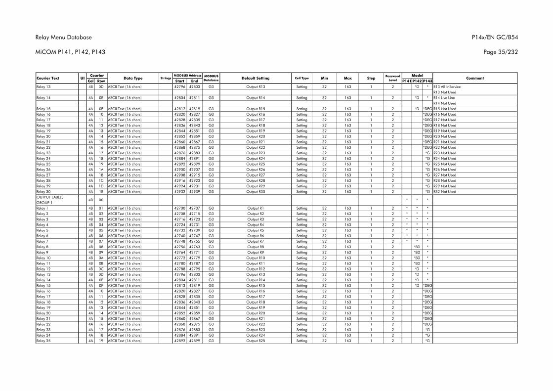
Relay Menu Database
MiCOM P141, P142, P143
P14x/EN GC/B54
Page 35/232
Col Row Start End P141 P142 P143Courier Text UI Data Type Strings
CourierCommentMODBUS
Database Default Setting Cell Type MinMODBUS Address Model
Max Step Password Level
Relay 13 4B 0D ASCII Text (16 chars) 42796 42803 G3 Output R13 Setting 32 163 1 2 *D * R13 AR InServiceR13 Not Used
Relay 14 4A 0E ASCII Text (16 chars) 42804 42811 G3 Output R14 Setting 32 163 1 2 *D * R14 Live LineR14 Not Used
Relay 15 4A 0F ASCII Text (16 chars) 42812 42819 G3 Output R15 Setting 32 163 1 2 *D *DEG R15 Not UsedRelay 16 4A 10 ASCII Text (16 chars) 42820 42827 G3 Output R16 Setting 32 163 1 2 *DEG R16 Not UsedRelay 17 4A 11 ASCII Text (16 chars) 42828 42835 G3 Output R17 Setting 32 163 1 2 *DEG R17 Not UsedRelay 18 4A 12 ASCII Text (16 chars) 42836 42843 G3 Output R18 Setting 32 163 1 2 *DEG R18 Not UsedRelay 19 4A 13 ASCII Text (16 chars) 42844 42851 G3 Output R19 Setting 32 163 1 2 *DEG R19 Not UsedRelay 20 4A 14 ASCII Text (16 chars) 42852 42859 G3 Output R20 Setting 32 163 1 2 *DEG R20 Not UsedRelay 21 4A 15 ASCII Text (16 chars) 42860 42867 G3 Output R21 Setting 32 163 1 2 *DEG R21 Not UsedRelay 22 4A 16 ASCII Text (16 chars) 42868 42875 G3 Output R22 Setting 32 163 1 2 *DEG R22 Not UsedRelay 23 4A 17 ASCII Text (16 chars) 42876 42883 G3 Output R23 Setting 32 163 1 2 *G R23 Not UsedRelay 24 4A 18 ASCII Text (16 chars) 42884 42891 G3 Output R24 Setting 32 163 1 2 *G R24 Not UsedRelay 25 4A 19 ASCII Text (16 chars) 42892 42899 G3 Output R25 Setting 32 163 1 2 *G R25 Not UsedRelay 26 4A 1A ASCII Text (16 chars) 42900 42907 G3 Output R26 Setting 32 163 1 2 *G R26 Not UsedRelay 27 4A 1B ASCII Text (16 chars) 42908 42915 G3 Output R27 Setting 32 163 1 2 *G R27 Not UsedRelay 28 4A 1C ASCII Text (16 chars) 42916 42923 G3 Output R28 Setting 32 163 1 2 *G R28 Not UsedRelay 29 4A 1D ASCII Text (16 chars) 42924 42931 G3 Output R29 Setting 32 163 1 2 *G R29 Not UsedRelay 30 4A 1E ASCII Text (16 chars) 42932 42939 G3 Output R30 Setting 32 163 1 2 *G R32 Not UsedOUTPUT LABELSGROUP 1Relay 1 4B 01 ASCII Text (16 chars) 42700 42707 G3 Output R1 Setting 32 163 1 2 * * *Relay 2 4B 02 ASCII Text (16 chars) 42708 42715 G3 Output R2 Setting 32 163 1 2 * * *Relay 3 4B 03 ASCII Text (16 chars) 42716 42723 G3 Output R3 Setting 32 163 1 2 * * *Relay 4 4B 04 ASCII Text (16 chars) 42724 42731 G3 Output R4 Setting 32 163 1 2 * * *Relay 5 4B 05 ASCII Text (16 chars) 42732 42739 G3 Output R5 Setting 32 163 1 2 * * *Relay 6 4B 06 ASCII Text (16 chars) 42740 42747 G3 Output R6 Setting 32 163 1 2 * * *Relay 7 4B 07 ASCII Text (16 chars) 42748 42755 G3 Output R7 Setting 32 163 1 2 * * *Relay 8 4B 08 ASCII Text (16 chars) 42756 42763 G3 Output R8 Setting 32 163 1 2 *BD *Relay 9 4B 09 ASCII Text (16 chars) 42764 42771 G3 Output R9 Setting 32 163 1 2 *BD *Relay 10 4B 0A ASCII Text (16 chars) 42772 42779 G3 Output R10 Setting 32 163 1 2 *BD *Relay 11 4B 0B ASCII Text (16 chars) 42780 42787 G3 Output R11 Setting 32 163 1 2 *BD *Relay 12 4B 0C ASCII Text (16 chars) 42788 42795 G3 Output R12 Setting 32 163 1 2 *D *Relay 13 4B 0D ASCII Text (16 chars) 42796 42803 G3 Output R13 Setting 32 163 1 2 *D *Relay 14 4A 0E ASCII Text (16 chars) 42804 42811 G3 Output R14 Setting 32 163 1 2 *D *Relay 15 4A 0F ASCII Text (16 chars) 42812 42819 G3 Output R15 Setting 32 163 1 2 *D *DEGRelay 16 4A 10 ASCII Text (16 chars) 42820 42827 G3 Output R16 Setting 32 163 1 2 *DEGRelay 17 4A 11 ASCII Text (16 chars) 42828 42835 G3 Output R17 Setting 32 163 1 2 *DEGRelay 18 4A 12 ASCII Text (16 chars) 42836 42843 G3 Output R18 Setting 32 163 1 2 *DEGRelay 19 4A 13 ASCII Text (16 chars) 42844 42851 G3 Output R19 Setting 32 163 1 2 *DEGRelay 20 4A 14 ASCII Text (16 chars) 42852 42859 G3 Output R20 Setting 32 163 1 2 *DEGRelay 21 4A 15 ASCII Text (16 chars) 42860 42867 G3 Output R21 Setting 32 163 1 2 *DEGRelay 22 4A 16 ASCII Text (16 chars) 42868 42875 G3 Output R22 Setting 32 163 1 2 *DEGRelay 23 4A 17 ASCII Text (16 chars) 42876 42883 G3 Output R23 Setting 32 163 1 2 *GRelay 24 4A 18 ASCII Text (16 chars) 42884 42891 G3 Output R24 Setting 32 163 1 2 *GRelay 25 4A 19 ASCII Text (16 chars) 42892 42899 G3 Output R25 Setting 32 163 1 2 *G
4B 00 * * *
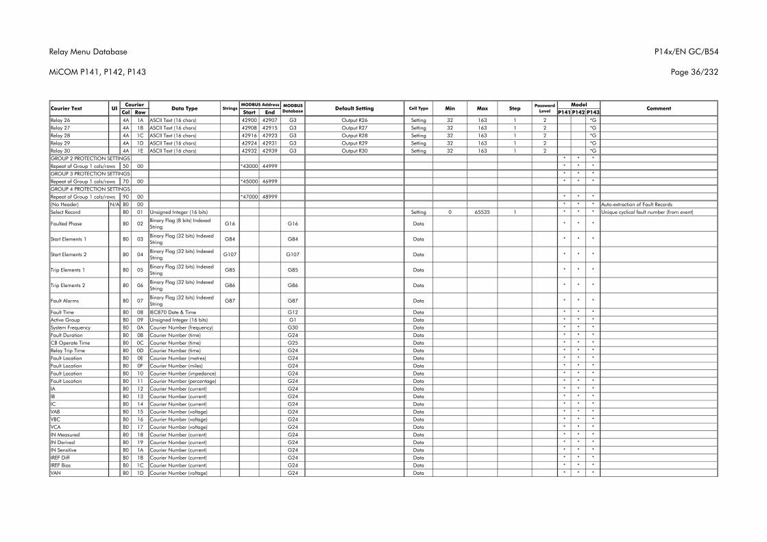
Relay Menu Database
MiCOM P141, P142, P143
P14x/EN GC/B54
Page 36/232
Col Row Start End P141 P142 P143Courier Text UI Data Type Strings
CourierCommentMODBUS
Database Default Setting Cell Type MinMODBUS Address Model
Max Step Password Level
Relay 26 4A 1A ASCII Text (16 chars) 42900 42907 G3 Output R26 Setting 32 163 1 2 *GRelay 27 4A 1B ASCII Text (16 chars) 42908 42915 G3 Output R27 Setting 32 163 1 2 *GRelay 28 4A 1C ASCII Text (16 chars) 42916 42923 G3 Output R28 Setting 32 163 1 2 *GRelay 29 4A 1D ASCII Text (16 chars) 42924 42931 G3 Output R29 Setting 32 163 1 2 *GRelay 30 4A 1E ASCII Text (16 chars) 42932 42939 G3 Output R30 Setting 32 163 1 2 *GGROUP 2 PROTECTION SETTINGS * * *Repeat of Group 1 cols/rows 50 00 *43000 44999 * * *GROUP 3 PROTECTION SETTINGS * * *Repeat of Group 1 cols/rows 70 00 *45000 46999 * * *GROUP 4 PROTECTION SETTINGSRepeat of Group 1 cols/rows 90 00 *47000 48999 * * *(No Header) N/A B0 00 * * * Auto-extraction of Fault RecordsSelect Record B0 01 Unsigned Integer (16 bits) Setting 0 65535 1 * * * Unique cyclical fault number (from event)
Faulted Phase B0 02Binary Flag (8 bits) Indexed String
G16 G16 Data * * *
Start Elements 1 B0 03Binary Flag (32 bits) Indexed String
G84 G84 Data * * *
Start Elements 2 B0 04Binary Flag (32 bits) Indexed String
G107 G107 Data * * *
Trip Elements 1 B0 05Binary Flag (32 bits) Indexed String
G85 G85 Data * * *
Trip Elements 2 B0 06Binary Flag (32 bits) Indexed String
G86 G86 Data * * *
Fault Alarms B0 07Binary Flag (32 bits) Indexed String
G87 G87 Data * * *
Fault Time B0 08 IEC870 Date & Time G12 Data * * *Active Group B0 09 Unsigned Integer (16 bits) G1 Data * * *System Frequency B0 0A Courier Number (frequency) G30 Data * * *Fault Duration B0 0B Courier Number (time) G24 Data * * *CB Operate Time B0 0C Courier Number (time) G25 Data * * *Relay Trip Time B0 0D Courier Number (time) G24 Data * * *Fault Location B0 0E Courier Number (metres) G24 Data * * *Fault Location B0 0F Courier Number (miles) G24 Data * * *Fault Location B0 10 Courier Number (impedance) G24 Data * * *Fault Location B0 11 Courier Number (percentage) G24 Data * * *IA B0 12 Courier Number (current) G24 Data * * *IB B0 13 Courier Number (current) G24 Data * * *IC B0 14 Courier Number (current) G24 Data * * *VAB B0 15 Courier Number (voltage) G24 Data * * *VBC B0 16 Courier Number (voltage) G24 Data * * *VCA B0 17 Courier Number (voltage) G24 Data * * *IN Measured B0 18 Courier Number (current) G24 Data * * *IN Derived B0 19 Courier Number (current) G24 Data * * *IN Sensitive B0 1A Courier Number (current) G24 Data * * *IREF Diff B0 1B Courier Number (current) G24 Data * * *IREF Bias B0 1C Courier Number (current) G24 Data * * *VAN B0 1D Courier Number (voltage) G24 Data * * *
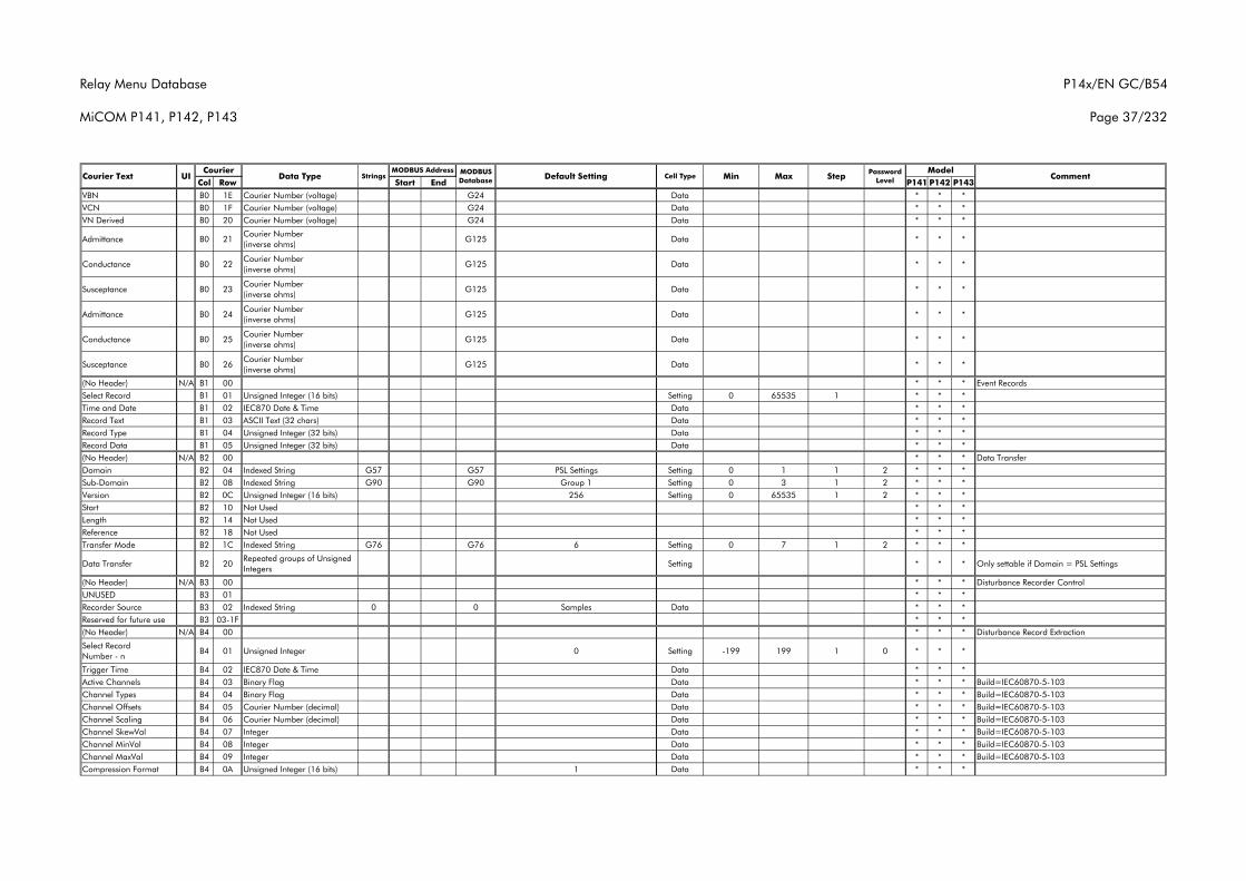
Relay Menu Database
MiCOM P141, P142, P143
P14x/EN GC/B54
Page 37/232
Col Row Start End P141 P142 P143Courier Text UI Data Type Strings
CourierCommentMODBUS
Database Default Setting Cell Type MinMODBUS Address Model
Max Step Password Level
VBN B0 1E Courier Number (voltage) G24 Data * * *VCN B0 1F Courier Number (voltage) G24 Data * * *VN Derived B0 20 Courier Number (voltage) G24 Data * * *
Admittance B0 21Courier Number (inverse ohms)
G125 Data * * *
Conductance B0 22Courier Number (inverse ohms)
G125 Data * * *
Susceptance B0 23Courier Number (inverse ohms)
G125 Data * * *
Admittance B0 24Courier Number (inverse ohms)
G125 Data * * *
Conductance B0 25Courier Number (inverse ohms)
G125 Data * * *
Susceptance B0 26Courier Number (inverse ohms)
G125 Data * * *
(No Header) N/A B1 00 * * * Event RecordsSelect Record B1 01 Unsigned Integer (16 bits) Setting 0 65535 1 * * *Time and Date B1 02 IEC870 Date & Time Data * * *Record Text B1 03 ASCII Text (32 chars) Data * * *Record Type B1 04 Unsigned Integer (32 bits) Data * * *Record Data B1 05 Unsigned Integer (32 bits) Data * * *(No Header) N/A B2 00 * * * Data TransferDomain B2 04 Indexed String G57 G57 PSL Settings Setting 0 1 1 2 * * *Sub-Domain B2 08 Indexed String G90 G90 Group 1 Setting 0 3 1 2 * * *Version B2 0C Unsigned Integer (16 bits) 256 Setting 0 65535 1 2 * * *Start B2 10 Not Used * * *Length B2 14 Not Used * * *Reference B2 18 Not Used * * *Transfer Mode B2 1C Indexed String G76 G76 6 Setting 0 7 1 2 * * *
Data Transfer B2 20Repeated groups of Unsigned Integers
Setting * * * Only settable if Domain = PSL Settings
(No Header) N/A B3 00 * * * Disturbance Recorder ControlUNUSED B3 01 * * *Recorder Source B3 02 Indexed String 0 0 Samples Data * * *Reserved for future use B3 03-1F * * *(No Header) N/A B4 00 * * * Disturbance Record Extraction
Select Record Number - n
B4 01 Unsigned Integer 0 Setting -199 199 1 0 * * *
Trigger Time B4 02 IEC870 Date & Time Data * * *Active Channels B4 03 Binary Flag Data * * * Build=IEC60870-5-103Channel Types B4 04 Binary Flag Data * * * Build=IEC60870-5-103Channel Offsets B4 05 Courier Number (decimal) Data * * * Build=IEC60870-5-103Channel Scaling B4 06 Courier Number (decimal) Data * * * Build=IEC60870-5-103Channel SkewVal B4 07 Integer Data * * * Build=IEC60870-5-103Channel MinVal B4 08 Integer Data * * * Build=IEC60870-5-103Channel MaxVal B4 09 Integer Data * * * Build=IEC60870-5-103Compression Format B4 0A Unsigned Integer (16 bits) 1 Data * * *
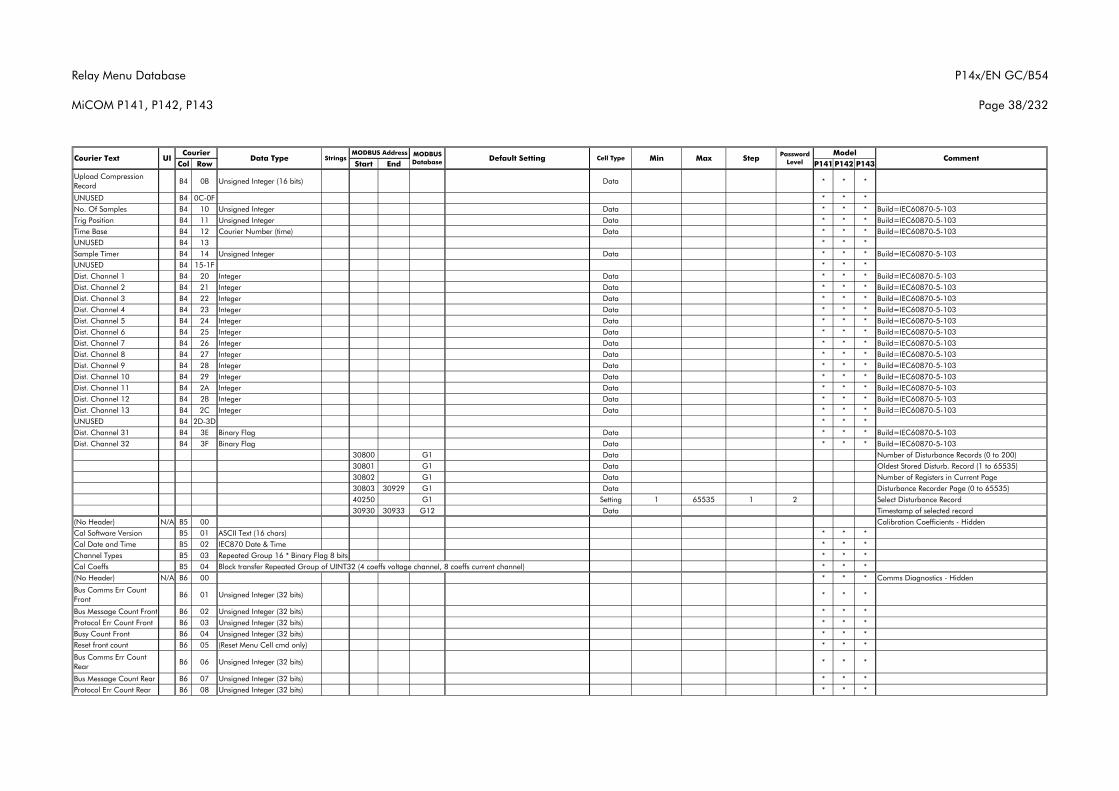
Relay Menu Database
MiCOM P141, P142, P143
P14x/EN GC/B54
Page 38/232
Col Row Start End P141 P142 P143Courier Text UI Data Type Strings
CourierCommentMODBUS
Database Default Setting Cell Type MinMODBUS Address Model
Max Step Password Level
Upload Compression Record
B4 0B Unsigned Integer (16 bits) Data * * *
UNUSED B4 0C-0F * * *No. Of Samples B4 10 Unsigned Integer Data * * * Build=IEC60870-5-103Trig Position B4 11 Unsigned Integer Data * * * Build=IEC60870-5-103Time Base B4 12 Courier Number (time) Data * * * Build=IEC60870-5-103UNUSED B4 13 * * *Sample Timer B4 14 Unsigned Integer Data * * * Build=IEC60870-5-103UNUSED B4 15-1F * * *Dist. Channel 1 B4 20 Integer Data * * * Build=IEC60870-5-103Dist. Channel 2 B4 21 Integer Data * * * Build=IEC60870-5-103Dist. Channel 3 B4 22 Integer Data * * * Build=IEC60870-5-103Dist. Channel 4 B4 23 Integer Data * * * Build=IEC60870-5-103Dist. Channel 5 B4 24 Integer Data * * * Build=IEC60870-5-103Dist. Channel 6 B4 25 Integer Data * * * Build=IEC60870-5-103Dist. Channel 7 B4 26 Integer Data * * * Build=IEC60870-5-103Dist. Channel 8 B4 27 Integer Data * * * Build=IEC60870-5-103Dist. Channel 9 B4 28 Integer Data * * * Build=IEC60870-5-103Dist. Channel 10 B4 29 Integer Data * * * Build=IEC60870-5-103Dist. Channel 11 B4 2A Integer Data * * * Build=IEC60870-5-103Dist. Channel 12 B4 2B Integer Data * * * Build=IEC60870-5-103Dist. Channel 13 B4 2C Integer Data * * * Build=IEC60870-5-103UNUSED B4 2D-3D * * *Dist. Channel 31 B4 3E Binary Flag Data * * * Build=IEC60870-5-103Dist. Channel 32 B4 3F Binary Flag Data * * * Build=IEC60870-5-103
30800 G1 Data Number of Disturbance Records (0 to 200)30801 G1 Data Oldest Stored Disturb. Record (1 to 65535)30802 G1 Data Number of Registers in Current Page30803 30929 G1 Data Disturbance Recorder Page (0 to 65535)40250 G1 Setting 1 65535 1 2 Select Disturbance Record30930 30933 G12 Data Timestamp of selected record
(No Header) N/A B5 00 Calibration Coefficients - HiddenCal Software Version B5 01 ASCII Text (16 chars) * * *Cal Date and Time B5 02 IEC870 Date & Time * * *Channel Types B5 03 Repeated Group 16 * Binary Flag 8 bits * * *Cal Coeffs B5 04 Block transfer Repeated Group of UINT32 (4 coeffs voltage channel, 8 coeffs current channel) * * *(No Header) N/A B6 00 * * * Comms Diagnostics - Hidden
Bus Comms Err Count Front
B6 01 Unsigned Integer (32 bits) * * *
Bus Message Count Front B6 02 Unsigned Integer (32 bits) * * *Protocol Err Count Front B6 03 Unsigned Integer (32 bits) * * *Busy Count Front B6 04 Unsigned Integer (32 bits) * * *Reset front count B6 05 (Reset Menu Cell cmd only) * * *
Bus Comms Err Count Rear
B6 06 Unsigned Integer (32 bits) * * *
Bus Message Count Rear B6 07 Unsigned Integer (32 bits) * * *Protocol Err Count Rear B6 08 Unsigned Integer (32 bits) * * *
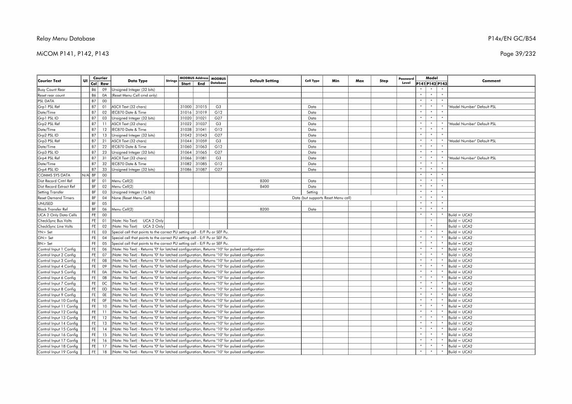
Relay Menu Database
MiCOM P141, P142, P143
P14x/EN GC/B54
Page 39/232
Col Row Start End P141 P142 P143Courier Text UI Data Type Strings
CourierCommentMODBUS
Database Default Setting Cell Type MinMODBUS Address Model
Max Step Password Level
Busy Count Rear B6 09 Unsigned Integer (32 bits) * * *Reset rear count B6 0A (Reset Menu Cell cmd only) * * *PSL DATA B7 00 * * *Grp1 PSL Ref B7 01 ASCII Text (32 chars) 31000 31015 G3 Data * * * "Model Number" Default PSLDate/Time B7 02 IEC870 Date & Time 31016 31019 G12 Data * * *Grp1 PSL ID B7 03 Unsigned Integer (32 bits) 31020 31021 G27 Data * * *Grp2 PSL Ref B7 11 ASCII Text (32 chars) 31022 31037 G3 Data * * * "Model Number" Default PSLDate/Time B7 12 IEC870 Date & Time 31038 31041 G12 Data * * *Grp2 PSL ID B7 13 Unsigned Integer (32 bits) 31042 31043 G27 Data * * *Grp3 PSL Ref B7 21 ASCII Text (32 chars) 31044 31059 G3 Data * * * "Model Number" Default PSLDate/Time B7 22 IEC870 Date & Time 31060 31063 G12 Data * * *Grp3 PSL ID B7 23 Unsigned Integer (32 bits) 31064 31065 G27 Data * * *Grp4 PSL Ref B7 31 ASCII Text (32 chars) 31066 31081 G3 Data * * * "Model Number" Default PSLDate/Time B7 32 IEC870 Date & Time 31082 31085 G12 Data * * *Grp4 PSL ID B7 33 Unsigned Integer (32 bits) 31086 31087 G27 Data * * *COMMS SYS DATA N/A BF 00 * * *Dist Record Cntrl Ref BF 01 Menu Cell(2) B300 Data * * *Dist Record Extract Ref BF 02 Menu Cell(2) B400 Data * * *Setting Transfer BF 03 Unsigned Integer (16 bits) Setting * * *Reset Demand Timers BF 04 None (Reset Menu Cell) * * *UNUSED BF 05 * * *Block Transfer Ref BF 06 Menu Cell(2) B200 Data * * *UCA 2 Only Data Cells FE 00 * * * Build = UCA2CheckSync Bus Volts FE 01 (Note: No Text) UCA 2 Only * Build = UCA2CheckSync Line Volts FE 02 (Note: No Text) UCA 2 Only * Build = UCA2YN> Set FE 03 * * * Build = UCA2GN> Set FE 04 * * * Build = UCA2BN> Set FE 05 * * * Build = UCA2Control Input 1 Config FE 06 * * * Build = UCA2Control Input 2 Config FE 07 * * * Build = UCA2Control Input 3 Config FE 08 * * * Build = UCA2Control Input 4 Config FE 09 * * * Build = UCA2Control Input 5 Config FE 0A * * * Build = UCA2Control Input 6 Config FE 0B * * * Build = UCA2Control Input 7 Config FE 0C * * * Build = UCA2Control Input 8 Config FE 0D * * * Build = UCA2Control Input 9 Config FE 0E * * * Build = UCA2Control Input 10 Config FE 0F * * * Build = UCA2Control Input 11 Config FE 10 * * * Build = UCA2Control Input 12 Config FE 11 * * * Build = UCA2Control Input 13 Config FE 12 * * * Build = UCA2Control Input 14 Config FE 13 * * * Build = UCA2Control Input 15 Config FE 14 * * * Build = UCA2Control Input 16 Config FE 15 * * * Build = UCA2Control Input 17 Config FE 16 * * * Build = UCA2Control Input 18 Config FE 17 * * * Build = UCA2Control Input 19 Config FE 18 * * * Build = UCA2
(Note: No Text) - Returns "0" for latched configuration, Returns "10" for pulsed configuration(Note: No Text) - Returns "0" for latched configuration, Returns "10" for pulsed configuration(Note: No Text) - Returns "0" for latched configuration, Returns "10" for pulsed configuration(Note: No Text) - Returns "0" for latched configuration, Returns "10" for pulsed configuration(Note: No Text) - Returns "0" for latched configuration, Returns "10" for pulsed configuration
(Note: No Text) - Returns "0" for latched configuration, Returns "10" for pulsed configuration
(Note: No Text) - Returns "0" for latched configuration, Returns "10" for pulsed configuration(Note: No Text) - Returns "0" for latched configuration, Returns "10" for pulsed configuration(Note: No Text) - Returns "0" for latched configuration, Returns "10" for pulsed configuration(Note: No Text) - Returns "0" for latched configuration, Returns "10" for pulsed configuration
(Note: No Text) - Returns "0" for latched configuration, Returns "10" for pulsed configuration(Note: No Text) - Returns "0" for latched configuration, Returns "10" for pulsed configuration(Note: No Text) - Returns "0" for latched configuration, Returns "10" for pulsed configuration(Note: No Text) - Returns "0" for latched configuration, Returns "10" for pulsed configuration
Special cell that points to the correct PU setting cell - E/F Pu or SEF Pu.Special cell that points to the correct PU setting cell - E/F Pu or SEF Pu.Special cell that points to the correct PU setting cell - E/F Pu or SEF Pu.
Data (but supports Reset Menu cell)
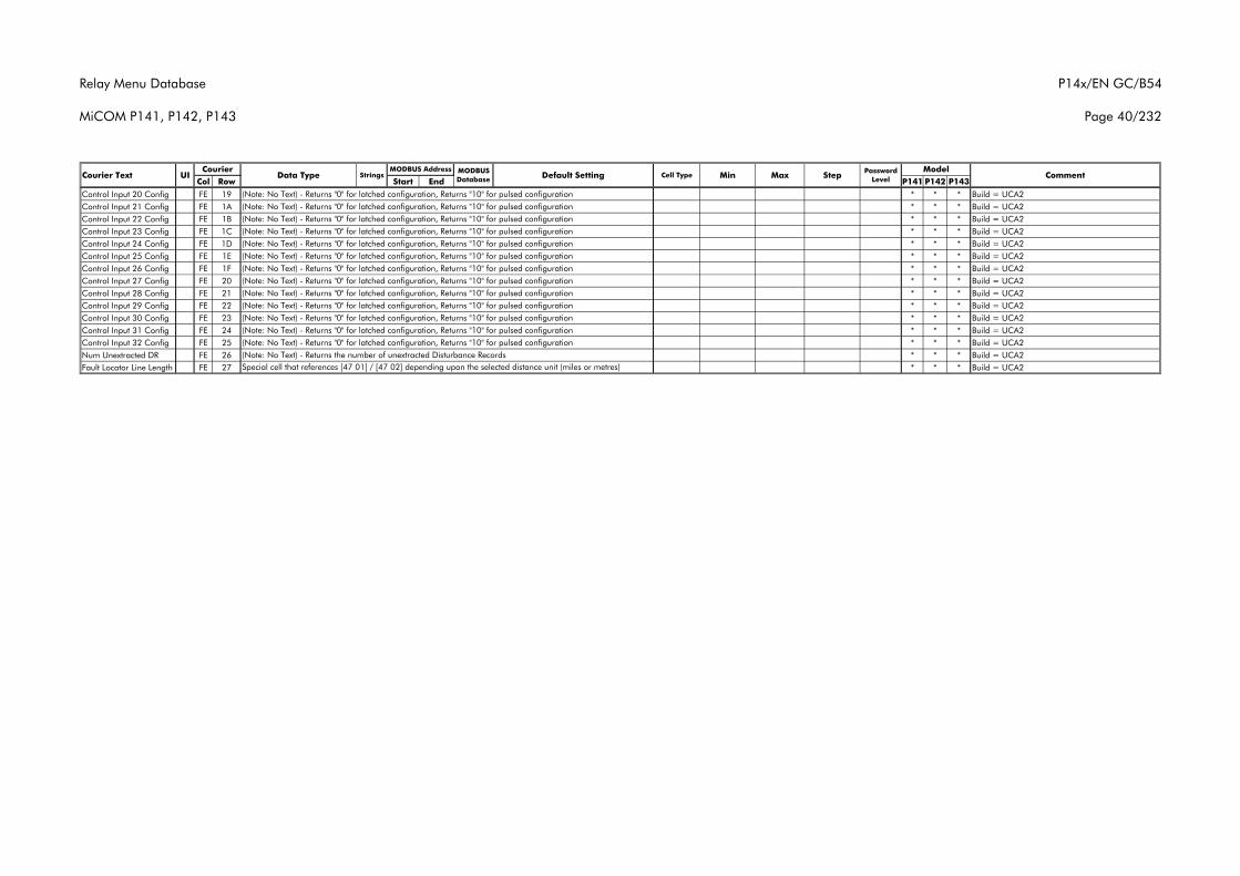
Relay Menu Database
MiCOM P141, P142, P143
P14x/EN GC/B54
Page 40/232
Col Row Start End P141 P142 P143Courier Text UI Data Type Strings
CourierCommentMODBUS
Database Default Setting Cell Type MinMODBUS Address Model
Max Step Password Level
Control Input 20 Config FE 19 * * * Build = UCA2Control Input 21 Config FE 1A * * * Build = UCA2Control Input 22 Config FE 1B * * * Build = UCA2Control Input 23 Config FE 1C * * * Build = UCA2Control Input 24 Config FE 1D * * * Build = UCA2Control Input 25 Config FE 1E * * * Build = UCA2Control Input 26 Config FE 1F * * * Build = UCA2Control Input 27 Config FE 20 * * * Build = UCA2Control Input 28 Config FE 21 * * * Build = UCA2Control Input 29 Config FE 22 * * * Build = UCA2Control Input 30 Config FE 23 * * * Build = UCA2Control Input 31 Config FE 24 * * * Build = UCA2Control Input 32 Config FE 25 * * * Build = UCA2Num Unextracted DR FE 26 * * * Build = UCA2Fault Locator Line Length FE 27 * * * Build = UCA2Special cell that references [47 01] / [47 02] depending upon the selected distance unit (miles or metres)
(Note: No Text) - Returns "0" for latched configuration, Returns "10" for pulsed configuration(Note: No Text) - Returns "0" for latched configuration, Returns "10" for pulsed configuration(Note: No Text) - Returns the number of unextracted Disturbance Records
(Note: No Text) - Returns "0" for latched configuration, Returns "10" for pulsed configuration(Note: No Text) - Returns "0" for latched configuration, Returns "10" for pulsed configuration(Note: No Text) - Returns "0" for latched configuration, Returns "10" for pulsed configuration(Note: No Text) - Returns "0" for latched configuration, Returns "10" for pulsed configuration
(Note: No Text) - Returns "0" for latched configuration, Returns "10" for pulsed configuration(Note: No Text) - Returns "0" for latched configuration, Returns "10" for pulsed configuration(Note: No Text) - Returns "0" for latched configuration, Returns "10" for pulsed configuration(Note: No Text) - Returns "0" for latched configuration, Returns "10" for pulsed configuration
(Note: No Text) - Returns "0" for latched configuration, Returns "10" for pulsed configuration(Note: No Text) - Returns "0" for latched configuration, Returns "10" for pulsed configuration(Note: No Text) - Returns "0" for latched configuration, Returns "10" for pulsed configuration
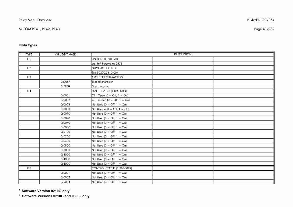
Relay Menu Database
MiCOM P141, P142, P143
P14x/EN GC/B54
Page 41/232
TYPE VALUE/BIT MASK
G1 UNSIGNED INTEGER
eg. 5678 stored as 5678
G2 NUMERIC SETTING
See 50300.3110.004
G3 ASCII TEXT CHARACTERS
0x00FF Second character
0xFF00 First character
G4 PLANT STATUS (1 REGISTER)
0x0001 CB1 Open (0 = Off, 1 = On)
0x0002 CB1 Closed (0 = Off, 1 = On)
0x0004 Not Used (0 = Off, 1 = On)
0x0008 Not Used 4 (0 = Off, 1 = On)
0x0010 Not Used (0 = Off, 1 = On)
0x0020 Not Used (0 = Off, 1 = On)
0x0040 Not Used (0 = Off, 1 = On)
0x0080 Not Used (0 = Off, 1 = On)
0x0100 Not Used (0 = Off, 1 = On)
0x0200 Not Used (0 = Off, 1 = On)
0x0400 Not Used (0 = Off, 1 = On)
0x0800 Not Used (0 = Off, 1 = On)
0x1000 Not Used (0 = Off, 1 = On)
0x2000 Not Used (0 = Off, 1 = On)
0x4000 Not Used (0 = Off, 1 = On)
0x8000 Not Used (0 = Off, 1 = On)
G5 CONTROL STATUS (1 REGISTER)
0x0001 Not Used (0 = Off, 1 = On)
0x0002 Not Used (0 = Off, 1 = On)
0x0004 Not Used (0 = Off, 1 = On)
Data Types
DESCRIPTION
1 Software Version 0210G only2 Software Versions 0210G and 0300J only
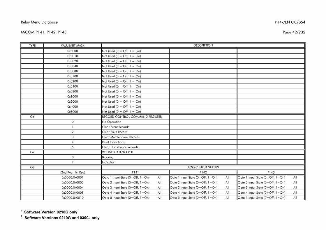
Relay Menu Database
MiCOM P141, P142, P143
P14x/EN GC/B54
Page 42/232
TYPE VALUE/BIT MASK DESCRIPTION
0x0008 Not Used (0 = Off, 1 = On)
0x0010 Not Used (0 = Off, 1 = On)
0x0020 Not Used (0 = Off, 1 = On)
0x0040 Not Used (0 = Off, 1 = On)
0x0080 Not Used (0 = Off, 1 = On)
0x0100 Not Used (0 = Off, 1 = On)
0x0200 Not Used (0 = Off, 1 = On)
0x0400 Not Used (0 = Off, 1 = On)
0x0800 Not Used (0 = Off, 1 = On)
0x1000 Not Used (0 = Off, 1 = On)
0x2000 Not Used (0 = Off, 1 = On)
0x4000 Not Used (0 = Off, 1 = On)
0x8000 Not Used (0 = Off, 1 = On)
G6 RECORD CONTROL COMMAND REGISTER
0 No Operation
1 Clear Event Records
2 Clear Fault Record
3 Clear Maintenance Records
4 Reset Indications
5 Clear Disturbance Records
G7 VTS INDICATE/BLOCK
0 Blocking
1 Indication
G8
(2nd Reg, 1st Reg) P141 P142 P143
0x0000,0x0001 Opto 1 Input State (0=Off, 1=On) All Opto 1 Input State (0=Off, 1=On) All Opto 1 Input State (0=Off, 1=On) All
0x0000,0x0002 Opto 2 Input State (0=Off, 1=On) All Opto 2 Input State (0=Off, 1=On) All Opto 2 Input State (0=Off, 1=On) All
0x0000,0x0004 Opto 3 Input State (0=Off, 1=On) All Opto 3 Input State (0=Off, 1=On) All Opto 3 Input State (0=Off, 1=On) All
0x0000,0x0008 Opto 4 Input State (0=Off, 1=On) All Opto 4 Input State (0=Off, 1=On) All Opto 4 Input State (0=Off, 1=On) All
0x0000,0x0010 Opto 5 Input State (0=Off, 1=On) All Opto 5 Input State (0=Off, 1=On) All Opto 5 Input State (0=Off, 1=On) All
LOGIC INPUT STATUS
1 Software Version 0210G only2 Software Versions 0210G and 0300J only
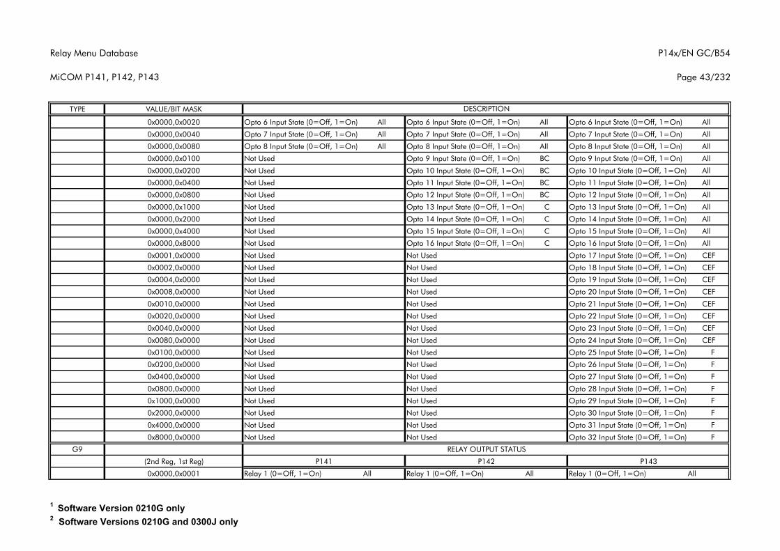
Relay Menu Database
MiCOM P141, P142, P143
P14x/EN GC/B54
Page 43/232
TYPE VALUE/BIT MASK DESCRIPTION
0x0000,0x0020 Opto 6 Input State (0=Off, 1=On) All Opto 6 Input State (0=Off, 1=On) All Opto 6 Input State (0=Off, 1=On) All
0x0000,0x0040 Opto 7 Input State (0=Off, 1=On) All Opto 7 Input State (0=Off, 1=On) All Opto 7 Input State (0=Off, 1=On) All
0x0000,0x0080 Opto 8 Input State (0=Off, 1=On) All Opto 8 Input State (0=Off, 1=On) All Opto 8 Input State (0=Off, 1=On) All
0x0000,0x0100 Not Used Opto 9 Input State (0=Off, 1=On) BC Opto 9 Input State (0=Off, 1=On) All
0x0000,0x0200 Not Used Opto 10 Input State (0=Off, 1=On) BC Opto 10 Input State (0=Off, 1=On) All
0x0000,0x0400 Not Used Opto 11 Input State (0=Off, 1=On) BC Opto 11 Input State (0=Off, 1=On) All
0x0000,0x0800 Not Used Opto 12 Input State (0=Off, 1=On) BC Opto 12 Input State (0=Off, 1=On) All
0x0000,0x1000 Not Used Opto 13 Input State (0=Off, 1=On) C Opto 13 Input State (0=Off, 1=On) All
0x0000,0x2000 Not Used Opto 14 Input State (0=Off, 1=On) C Opto 14 Input State (0=Off, 1=On) All
0x0000,0x4000 Not Used Opto 15 Input State (0=Off, 1=On) C Opto 15 Input State (0=Off, 1=On) All
0x0000,0x8000 Not Used Opto 16 Input State (0=Off, 1=On) C Opto 16 Input State (0=Off, 1=On) All
0x0001,0x0000 Not Used Not Used Opto 17 Input State (0=Off, 1=On) CEF
0x0002,0x0000 Not Used Not Used Opto 18 Input State (0=Off, 1=On) CEF
0x0004,0x0000 Not Used Not Used Opto 19 Input State (0=Off, 1=On) CEF
0x0008,0x0000 Not Used Not Used Opto 20 Input State (0=Off, 1=On) CEF
0x0010,0x0000 Not Used Not Used Opto 21 Input State (0=Off, 1=On) CEF
0x0020,0x0000 Not Used Not Used Opto 22 Input State (0=Off, 1=On) CEF
0x0040,0x0000 Not Used Not Used Opto 23 Input State (0=Off, 1=On) CEF
0x0080,0x0000 Not Used Not Used Opto 24 Input State (0=Off, 1=On) CEF
0x0100,0x0000 Not Used Not Used Opto 25 Input State (0=Off, 1=On) F
0x0200,0x0000 Not Used Not Used Opto 26 Input State (0=Off, 1=On) F
0x0400,0x0000 Not Used Not Used Opto 27 Input State (0=Off, 1=On) F
0x0800,0x0000 Not Used Not Used Opto 28 Input State (0=Off, 1=On) F
0x1000,0x0000 Not Used Not Used Opto 29 Input State (0=Off, 1=On) F
0x2000,0x0000 Not Used Not Used Opto 30 Input State (0=Off, 1=On) F
0x4000,0x0000 Not Used Not Used Opto 31 Input State (0=Off, 1=On) F
0x8000,0x0000 Not Used Not Used Opto 32 Input State (0=Off, 1=On) F
G9
(2nd Reg, 1st Reg) P141 P142 P143
0x0000,0x0001 Relay 1 (0=Off, 1=On) All Relay 1 (0=Off, 1=On) All Relay 1 (0=Off, 1=On) All
RELAY OUTPUT STATUS
1 Software Version 0210G only2 Software Versions 0210G and 0300J only
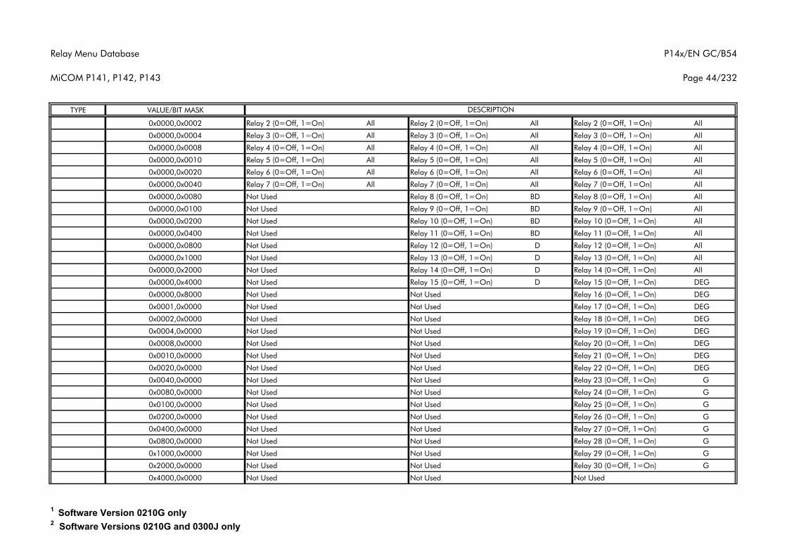
Relay Menu Database
MiCOM P141, P142, P143
P14x/EN GC/B54
Page 44/232
TYPE VALUE/BIT MASK DESCRIPTION
0x0000,0x0002 Relay 2 (0=Off, 1=On) All Relay 2 (0=Off, 1=On) All Relay 2 (0=Off, 1=On) All
0x0000,0x0004 Relay 3 (0=Off, 1=On) All Relay 3 (0=Off, 1=On) All Relay 3 (0=Off, 1=On) All
0x0000,0x0008 Relay 4 (0=Off, 1=On) All Relay 4 (0=Off, 1=On) All Relay 4 (0=Off, 1=On) All
0x0000,0x0010 Relay 5 (0=Off, 1=On) All Relay 5 (0=Off, 1=On) All Relay 5 (0=Off, 1=On) All
0x0000,0x0020 Relay 6 (0=Off, 1=On) All Relay 6 (0=Off, 1=On) All Relay 6 (0=Off, 1=On) All
0x0000,0x0040 Relay 7 (0=Off, 1=On) All Relay 7 (0=Off, 1=On) All Relay 7 (0=Off, 1=On) All
0x0000,0x0080 Not Used Relay 8 (0=Off, 1=On) BD Relay 8 (0=Off, 1=On) All
0x0000,0x0100 Not Used Relay 9 (0=Off, 1=On) BD Relay 9 (0=Off, 1=On) All
0x0000,0x0200 Not Used Relay 10 (0=Off, 1=On) BD Relay 10 (0=Off, 1=On) All
0x0000,0x0400 Not Used Relay 11 (0=Off, 1=On) BD Relay 11 (0=Off, 1=On) All
0x0000,0x0800 Not Used Relay 12 (0=Off, 1=On) D Relay 12 (0=Off, 1=On) All
0x0000,0x1000 Not Used Relay 13 (0=Off, 1=On) D Relay 13 (0=Off, 1=On) All
0x0000,0x2000 Not Used Relay 14 (0=Off, 1=On) D Relay 14 (0=Off, 1=On) All
0x0000,0x4000 Not Used Relay 15 (0=Off, 1=On) D Relay 15 (0=Off, 1=On) DEG
0x0000,0x8000 Not Used Not Used Relay 16 (0=Off, 1=On) DEG
0x0001,0x0000 Not Used Not Used Relay 17 (0=Off, 1=On) DEG
0x0002,0x0000 Not Used Not Used Relay 18 (0=Off, 1=On) DEG
0x0004,0x0000 Not Used Not Used Relay 19 (0=Off, 1=On) DEG
0x0008,0x0000 Not Used Not Used Relay 20 (0=Off, 1=On) DEG
0x0010,0x0000 Not Used Not Used Relay 21 (0=Off, 1=On) DEG
0x0020,0x0000 Not Used Not Used Relay 22 (0=Off, 1=On) DEG
0x0040,0x0000 Not Used Not Used Relay 23 (0=Off, 1=On) G
0x0080,0x0000 Not Used Not Used Relay 24 (0=Off, 1=On) G
0x0100,0x0000 Not Used Not Used Relay 25 (0=Off, 1=On) G
0x0200,0x0000 Not Used Not Used Relay 26 (0=Off, 1=On) G
0x0400,0x0000 Not Used Not Used Relay 27 (0=Off, 1=On) G
0x0800,0x0000 Not Used Not Used Relay 28 (0=Off, 1=On) G
0x1000,0x0000 Not Used Not Used Relay 29 (0=Off, 1=On) G
0x2000,0x0000 Not Used Not Used Relay 30 (0=Off, 1=On) G
0x4000,0x0000 Not Used Not Used Not Used
1 Software Version 0210G only2 Software Versions 0210G and 0300J only
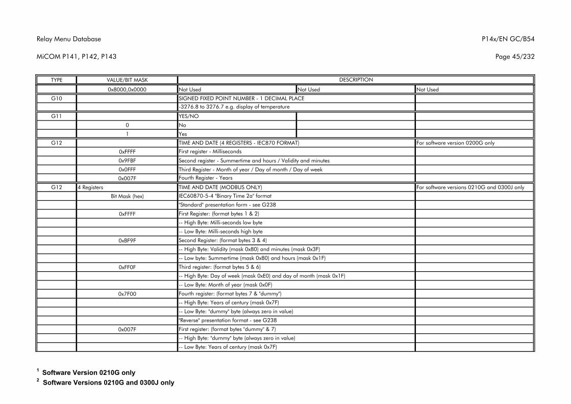
Relay Menu Database
MiCOM P141, P142, P143
P14x/EN GC/B54
Page 45/232
TYPE VALUE/BIT MASK DESCRIPTION
0x8000,0x0000 Not Used Not Used Not Used
G10 SIGNED FIXED POINT NUMBER - 1 DECIMAL PLACE
G11 YES/NO
0 No
1 Yes
G12 TIME AND DATE (4 REGISTERS - IEC870 FORMAT) For software version 0200G only
0xFFFF
0x9FBF Second register - Summertime and hours / Validity and minutes
0x0FFF Third Register - Month of year / Day of month / Day of week
0x007F
G12 4 Registers For software versions 0210G and 0300J only
Bit Mask (hex)
0xFFFF
0xBF9F
0xFF0F
0x7F00
0x007F
TIME AND DATE (MODBUS ONLY)
IEC60870-5-4 "Binary Time 2a" format
"Standard" presentation form - see G238
-- High Byte: Validity (mask 0x80) and minutes (mask 0x3F)
-- Low byte: Summertime (mask 0x80) and hours (mask 0x1F)
Third register: (format bytes 5 & 6)
-- High Byte: Day of week (mask 0xE0) and day of month (mask 0x1F)
"Reverse" presentation format - see G238
First register: (format bytes "dummy" & 7)
-3276.8 to 3276.7 e.g. display of temperature
-- Low Byte: Month of year (mask 0x0F)
Fourth register: (format bytes 7 & "dummy")
-- High Byte: Years of century (mask 0x7F)
-- Low Byte: "dummy" byte (always zero in value)
-- Low Byte: Years of century (mask 0x7F)
First register - Milliseconds
Fourth Register - Years
-- High Byte: "dummy" byte (always zero in value)
First Register: (format bytes 1 & 2)
-- High Byte: Milli-seconds low byte
-- Low Byte: Milli-seconds high byte
Second Register: (format bytes 3 & 4)
1 Software Version 0210G only2 Software Versions 0210G and 0300J only
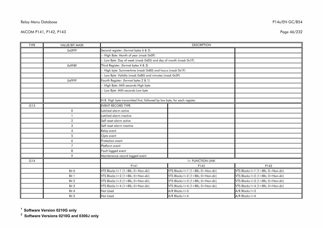
Relay Menu Database
MiCOM P141, P142, P143
P14x/EN GC/B54
Page 46/232
TYPE VALUE/BIT MASK DESCRIPTION
0x0FFF
0x9FBF
0xFFFF
G13 EVENT RECORD TYPE
0 Latched alarm active
1 Latched alarm inactive
2 Self reset alarm active
3 Self reset alarm inactive
4 Relay event
5 Opto event
6 Protection event
7 Platform event
8 Fault logged event
9 Maintenance record logged event
G14
P141 P142 P143
Bit 0 VTS Blocks I>1 (1=Blk; 0=Non-dir) VTS Blocks I>1 (1=Blk; 0=Non-dir) VTS Blocks I>1 (1=Blk; 0=Non-dir)
Bit 1 VTS Blocks I>2 (1=Blk; 0=Non-dir) VTS Blocks I>2 (1=Blk; 0=Non-dir) VTS Blocks I>2 (1=Blk; 0=Non-dir)
Bit 2 VTS Blocks I>3 (1=Blk; 0=Non-dir) VTS Blocks I>3 (1=Blk; 0=Non-dir) VTS Blocks I>3 (1=Blk; 0=Non-dir)
Bit 3 VTS Blocks I>4 (1=Blk; 0=Non-dir) VTS Blocks I>4 (1=Blk; 0=Non-dir) VTS Blocks I>4 (1=Blk; 0=Non-dir)
Bit 4 Not Used A/R Blocks I>3 A/R Blocks I>3
Bit 5 Not Used A/R Blocks I>4 A/R Blocks I>4
Fourth Register: (format bytes 2 & 1)
N.B. High byte transmitted first, followed by low byte, for each register.
I> FUNCTION LINK
-- High Byte: Milli-seconds High byte
-- Low Byte: Milli-seconds Low byte
Second register: (format bytes 6 & 5)
-- High Byte: Month of year (mask 0x0F)
-- Low Byte: Day of week (mask 0xE0) and day of month (mask 0x1F)
-- High byte: Summertime (mask 0x80) and hours (mask 0x1F)
-- Low Byte: Validity (mask 0x80) and minutes (mask 0x3F)
Third Register: (format bytes 4 & 3)
1 Software Version 0210G only2 Software Versions 0210G and 0300J only
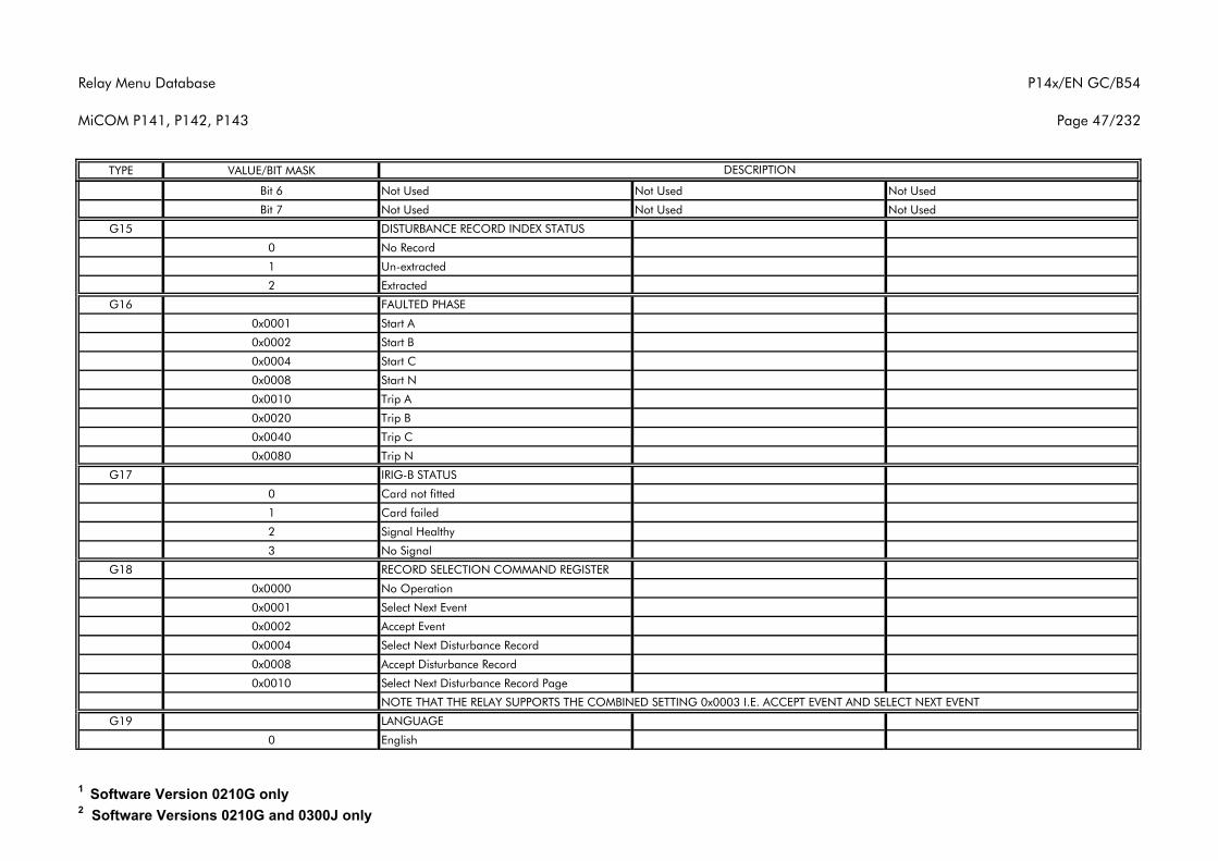
Relay Menu Database
MiCOM P141, P142, P143
P14x/EN GC/B54
Page 47/232
TYPE VALUE/BIT MASK DESCRIPTION
Bit 6 Not Used Not Used Not Used
Bit 7 Not Used Not Used Not Used
G15 DISTURBANCE RECORD INDEX STATUS
0 No Record
1 Un-extracted
2 Extracted
G16 FAULTED PHASE
0x0001 Start A
0x0002 Start B
0x0004 Start C
0x0008 Start N
0x0010 Trip A
0x0020 Trip B
0x0040 Trip C
0x0080 Trip N
G17 IRIG-B STATUS
0 Card not fitted
1 Card failed
2 Signal Healthy
3 No Signal
G18 RECORD SELECTION COMMAND REGISTER
0x0000 No Operation
0x0001 Select Next Event
0x0002 Accept Event
0x0004 Select Next Disturbance Record
0x0008 Accept Disturbance Record
0x0010 Select Next Disturbance Record Page
NOTE THAT THE RELAY SUPPORTS THE COMBINED SETTING 0x0003 I.E. ACCEPT EVENT AND SELECT NEXT EVENT
G19 LANGUAGE
0 English
1 Software Version 0210G only2 Software Versions 0210G and 0300J only
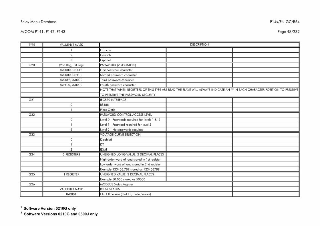
Relay Menu Database
MiCOM P141, P142, P143
P14x/EN GC/B54
Page 48/232
TYPE VALUE/BIT MASK DESCRIPTION
1 Francais
2 Deutsch
3 Espanol
G20 (2nd Reg, 1st Reg) PASSWORD (2 REGISTERS)
0x0000, 0x00FF First password character
0x0000, 0xFF00 Second password character
0x00FF, 0x0000 Third password character
0xFF00, 0x0000 Fourth password character
TO PRESERVE THE PASSWORD SECURITY
G21 IEC870 INTERFACE
0 RS485
1 Fibre Optic
G22 PASSWORD CONTROL ACCESS LEVEL
0 Level 0 - Passwords required for levels 1 & 2
1 Level 1 - Password required for level 2
2 Level 2 - No passwords required
G23 VOLTAGE CURVE SELECTION
0 Disabled
1 DT
2 IDMT
G24 2 REGISTERS UNSIGNED LONG VALUE, 3 DECIMAL PLACES
High order word of long stored in 1st register
Low order word of long stored in 2nd register
Example 123456.789 stored as 123456789
G25 1 REGISTER UNSIGNED VALUE, 3 DECIMAL PLACES
Example 50.050 stored as 50050
G26
VALUE/BIT MASK
0x0001
MODBUS Status Register
RELAY STATUS
Out Of Service (0=Out; 1=In Service)
NOTE THAT WHEN REGISTERS OF THIS TYPE ARE READ THE SLAVE WILL ALWAYS INDICATE AN "*" IN EACH CHARACTER POSITION TO PRESERVE
1 Software Version 0210G only2 Software Versions 0210G and 0300J only
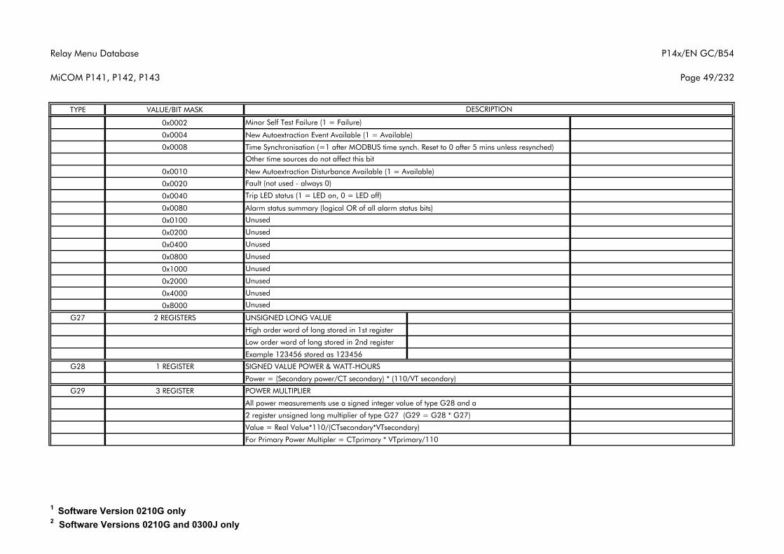
Relay Menu Database
MiCOM P141, P142, P143
P14x/EN GC/B54
Page 49/232
TYPE VALUE/BIT MASK DESCRIPTION
0x0002
0x0004 New Autoextraction Event Available (1 = Available)
0x0008 Time Synchronisation (=1 after MODBUS time synch. Reset to 0 after 5 mins unless resynched)
0x0010 New Autoextraction Disturbance Available (1 = Available)
0x0020
0x0040
0x0080 Alarm status summary (logical OR of all alarm status bits)
0x0100
0x0200
0x0400
0x0800
0x1000
0x2000
0x4000
0x8000
G27 2 REGISTERS UNSIGNED LONG VALUE
High order word of long stored in 1st register
Low order word of long stored in 2nd register
Example 123456 stored as 123456
G28 1 REGISTER
Power = (Secondary power/CT secondary) * (110/VT secondary)
G29 3 REGISTER
All power measurements use a signed integer value of type G28 and a
2 register unsigned long multiplier of type G27 (G29 = G28 * G27)
Value = Real Value*110/(CTsecondary*VTsecondary)
For Primary Power Multipler = CTprimary * VTprimary/110
Unused
SIGNED VALUE POWER & WATT-HOURS
POWER MULTIPLIER
Unused
Unused
Trip LED status (1 = LED on, 0 = LED off)
Minor Self Test Failure (1 = Failure)
Unused
Other time sources do not affect this bit
Fault (not used - always 0)
Unused
Unused
Unused
Unused
1 Software Version 0210G only2 Software Versions 0210G and 0300J only
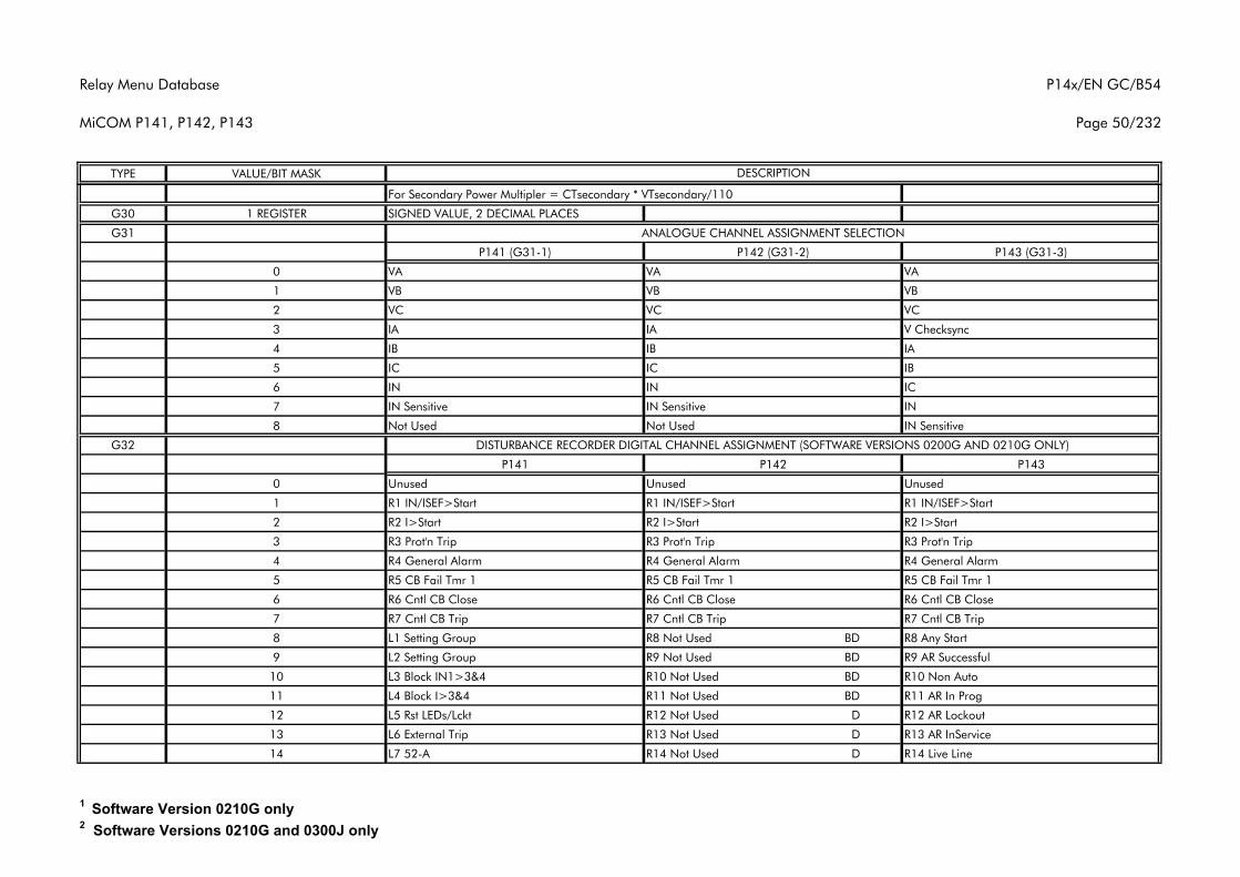
Relay Menu Database
MiCOM P141, P142, P143
P14x/EN GC/B54
Page 50/232
TYPE VALUE/BIT MASK DESCRIPTION
For Secondary Power Multipler = CTsecondary * VTsecondary/110
G30 1 REGISTER SIGNED VALUE, 2 DECIMAL PLACES
G31
P141 (G31-1) P142 (G31-2) P143 (G31-3)
0 VA VA VA
1 VB VB VB
2 VC VC VC
3 IA IA V Checksync
4 IB IB IA
5 IC IC IB
6 IN IN IC
7 IN Sensitive IN Sensitive IN
8 Not Used Not Used IN Sensitive
G32
P141 P142 P143
0 Unused Unused Unused
1 R1 IN/ISEF>Start R1 IN/ISEF>Start R1 IN/ISEF>Start
2 R2 I>Start R2 I>Start R2 I>Start
3 R3 Prot'n Trip R3 Prot'n Trip R3 Prot'n Trip
4 R4 General Alarm R4 General Alarm R4 General Alarm
5 R5 CB Fail Tmr 1 R5 CB Fail Tmr 1 R5 CB Fail Tmr 1
6 R6 Cntl CB Close R6 Cntl CB Close R6 Cntl CB Close
7 R7 Cntl CB Trip R7 Cntl CB Trip R7 Cntl CB Trip
8 L1 Setting Group R8 Not Used BD R8 Any Start
9 L2 Setting Group R9 Not Used BD R9 AR Successful
10 L3 Block IN1>3&4 R10 Not Used BD R10 Non Auto
11 L4 Block I>3&4 R11 Not Used BD R11 AR In Prog
12 L5 Rst LEDs/Lckt R12 Not Used D R12 AR Lockout
13 L6 External Trip R13 Not Used D R13 AR InService
14 L7 52-A R14 Not Used D R14 Live Line
DISTURBANCE RECORDER DIGITAL CHANNEL ASSIGNMENT (SOFTWARE VERSIONS 0200G AND 0210G ONLY)
ANALOGUE CHANNEL ASSIGNMENT SELECTION
1 Software Version 0210G only2 Software Versions 0210G and 0300J only
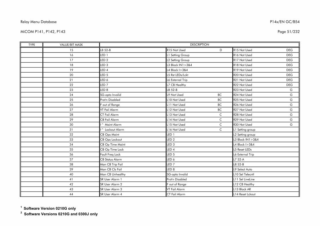
Relay Menu Database
MiCOM P141, P142, P143
P14x/EN GC/B54
Page 51/232
TYPE VALUE/BIT MASK DESCRIPTION
15 L8 52-B R15 Not Used D R15 Not Used DEG
16 LED 1 L1 Setting Group R16 Not Used DEG
17 LED 2 L2 Setting Group R17 Not Used DEG
18 LED 3 L3 Block IN1>3&4 R18 Not Used DEG
19 LED 4 L4 Block I>3&4 R19 Not Used DEG
20 LED 5 L5 Rst LEDs/Lckt R20 Not Used DEG
21 LED 6 L6 External Trip R21 Not Used DEG
22 LED 7 L7 CB Healthy R22 Not Used DEG
23 LED 8 L8 52-B R23 Not Used G
24 SG-opto Invalid L9 Not Used BC R24 Not Used G
25 Prot'n Disabled L10 Not Used BC R25 Not Used G
26 F out of Range L11 Not Used BC R26 Not Used G
27 VT Fail Alarm L12 Not Used BC R27 Not Used G
28 CT Fail Alarm L13 Not Used C R28 Not Used G
29 CB Fail Alarm L14 Not Used C R29 Not Used G
30 I^ Maint Alarm L15 Not Used C R30 Not Used G
31 I^ Lockout Alarm L16 Not Used C L1 Setting group
32 CB Ops Maint LED 1 L2 Setting group
33 CB Ops Lockout LED 2 L3 Block IN1>3&4
34 CB Op Time Maint LED 3 L4 Block I>3&4
35 CB Op Time Lock LED 4 L5 Reset LEDs
36 Fault Freq Lock LED 5 L6 External Trip
37 CB Status Alarm LED 6 L7 52-A
38 Man CB Trip Fail LED 7 L8 52-B
39 Man CB Cls Fail LED 8 L9 Select Auto
40 Man CB Unhealthy SG-opto Invalid L10 Sel Telecntl
41 SR User Alarm 1 Prot'n Disabled L11 Sel LiveLine
42 SR User Alarm 2 F out of Range L12 CB Healthy
43 SR User Alarm 3 VT Fail Alarm L13 Block AR
44 SR User Alarm 4 CT Fail Alarm L14 Reset Lckout
1 Software Version 0210G only2 Software Versions 0210G and 0300J only
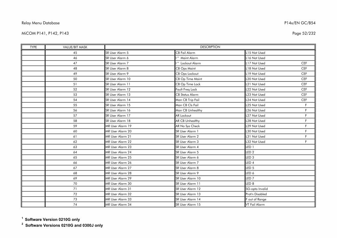
Relay Menu Database
MiCOM P141, P142, P143
P14x/EN GC/B54
Page 52/232
TYPE VALUE/BIT MASK DESCRIPTION
45 SR User Alarm 5 CB Fail Alarm L15 Not Used
46 SR User Alarm 6 I^ Maint Alarm L16 Not Used
47 SR User Alarm 7 I^ Lockout Alarm L17 Not Used CEF
48 SR User Alarm 8 CB Ops Maint L18 Not Used CEF
49 SR User Alarm 9 CB Ops Lockout L19 Not Used CEF
50 SR User Alarm 10 CB Op Time Maint L20 Not Used CEF
51 SR User Alarm 11 CB Op Time Lock L21 Not Used CEF
52 SR User Alarm 12 Fault Freq Lock L22 Not Used CEF
53 SR User Alarm 13 CB Status Alarm L23 Not Used CEF
54 SR User Alarm 14 Man CB Trip Fail L24 Not Used CEF
55 SR User Alarm 15 Man CB Cls Fail L25 Not Used F
56 SR User Alarm 16 Man CB Unhealthy L26 Not Used F
57 SR User Alarm 17 AR Lockout L27 Not Used F
58 SR User Alarm 18 AR CB Unhealthy L28 Not Used F
59 MR User Alarm 19 AR No Sys Check L29 Not Used F
60 MR User Alarm 20 SR User Alarm 1 L30 Not Used F
61 MR User Alarm 21 SR User Alarm 2 L31 Not Used F
62 MR User Alarm 22 SR User Alarm 3 L32 Not Used F
63 MR User Alarm 23 SR User Alarm 4 LED 1
64 MR User Alarm 24 SR User Alarm 5 LED 2
65 MR User Alarm 25 SR User Alarm 6 LED 3
66 MR User Alarm 26 SR User Alarm 7 LED 4
67 MR User Alarm 27 SR User Alarm 8 LED 5
68 MR User Alarm 28 SR User Alarm 9 LED 6
69 MR User Alarm 29 SR User Alarm 10 LED 7
70 MR User Alarm 30 SR User Alarm 11 LED 8
71 MR User Alarm 31 SR User Alarm 12 SG-opto Invalid
72 MR User Alarm 32 SR User Alarm 13 Prot'n Disabled
73 MR User Alarm 33 SR User Alarm 14 F out of Range
74 MR User Alarm 34 SR User Alarm 15 VT Fail Alarm
1 Software Version 0210G only2 Software Versions 0210G and 0300J only
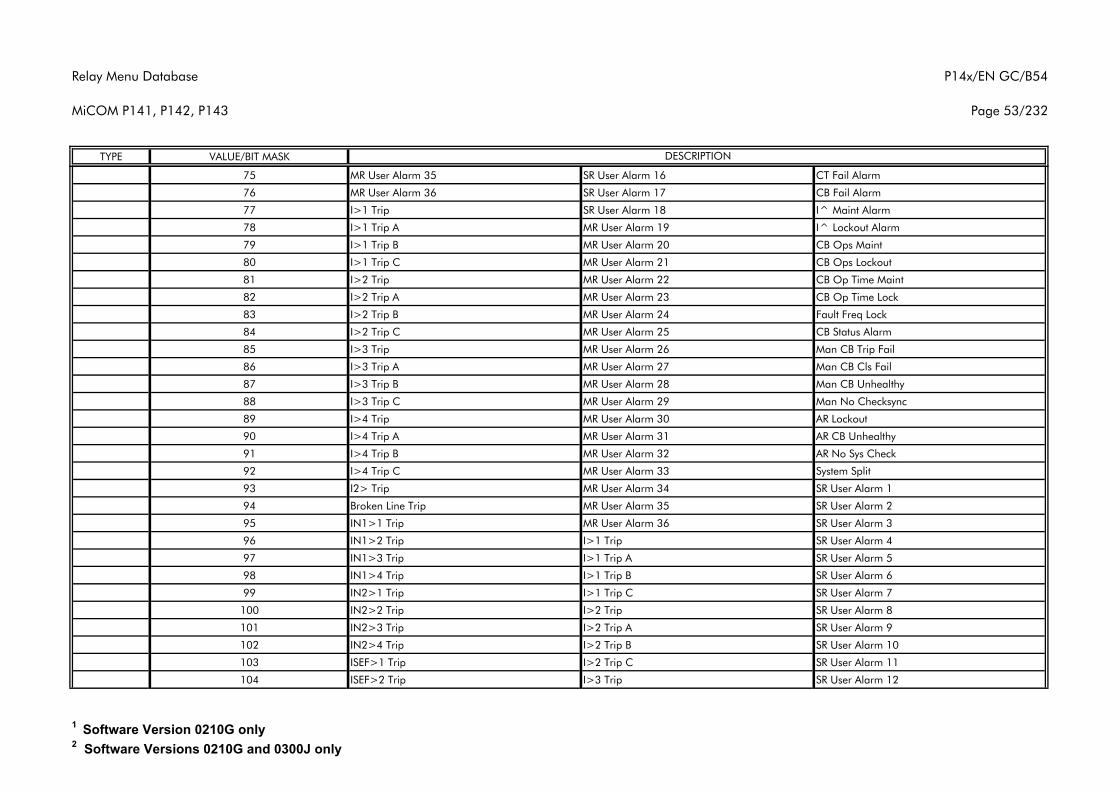
Relay Menu Database
MiCOM P141, P142, P143
P14x/EN GC/B54
Page 53/232
TYPE VALUE/BIT MASK DESCRIPTION
75 MR User Alarm 35 SR User Alarm 16 CT Fail Alarm
76 MR User Alarm 36 SR User Alarm 17 CB Fail Alarm
77 I>1 Trip SR User Alarm 18 I^ Maint Alarm
78 I>1 Trip A MR User Alarm 19 I^ Lockout Alarm
79 I>1 Trip B MR User Alarm 20 CB Ops Maint
80 I>1 Trip C MR User Alarm 21 CB Ops Lockout
81 I>2 Trip MR User Alarm 22 CB Op Time Maint
82 I>2 Trip A MR User Alarm 23 CB Op Time Lock
83 I>2 Trip B MR User Alarm 24 Fault Freq Lock
84 I>2 Trip C MR User Alarm 25 CB Status Alarm
85 I>3 Trip MR User Alarm 26 Man CB Trip Fail
86 I>3 Trip A MR User Alarm 27 Man CB Cls Fail
87 I>3 Trip B MR User Alarm 28 Man CB Unhealthy
88 I>3 Trip C MR User Alarm 29 Man No Checksync
89 I>4 Trip MR User Alarm 30 AR Lockout
90 I>4 Trip A MR User Alarm 31 AR CB Unhealthy
91 I>4 Trip B MR User Alarm 32 AR No Sys Check
92 I>4 Trip C MR User Alarm 33 System Split
93 I2> Trip MR User Alarm 34 SR User Alarm 1
94 Broken Line Trip MR User Alarm 35 SR User Alarm 2
95 IN1>1 Trip MR User Alarm 36 SR User Alarm 3
96 IN1>2 Trip I>1 Trip SR User Alarm 4
97 IN1>3 Trip I>1 Trip A SR User Alarm 5
98 IN1>4 Trip I>1 Trip B SR User Alarm 6
99 IN2>1 Trip I>1 Trip C SR User Alarm 7
100 IN2>2 Trip I>2 Trip SR User Alarm 8
101 IN2>3 Trip I>2 Trip A SR User Alarm 9
102 IN2>4 Trip I>2 Trip B SR User Alarm 10
103 ISEF>1 Trip I>2 Trip C SR User Alarm 11
104 ISEF>2 Trip I>3 Trip SR User Alarm 12
1 Software Version 0210G only2 Software Versions 0210G and 0300J only
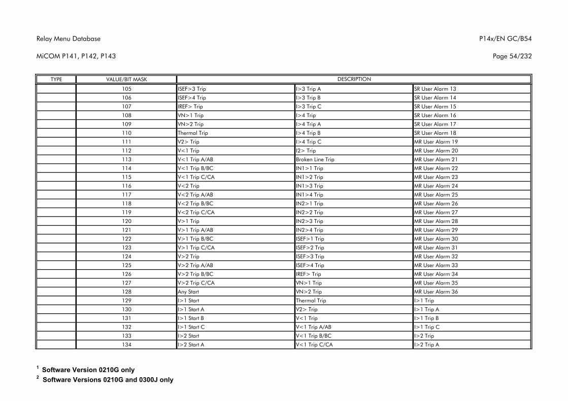
Relay Menu Database
MiCOM P141, P142, P143
P14x/EN GC/B54
Page 54/232
TYPE VALUE/BIT MASK DESCRIPTION
105 ISEF>3 Trip I>3 Trip A SR User Alarm 13
106 ISEF>4 Trip I>3 Trip B SR User Alarm 14
107 IREF> Trip I>3 Trip C SR User Alarm 15
108 VN>1 Trip I>4 Trip SR User Alarm 16
109 VN>2 Trip I>4 Trip A SR User Alarm 17
110 Thermal Trip I>4 Trip B SR User Alarm 18
111 V2> Trip I>4 Trip C MR User Alarm 19
112 V<1 Trip I2> Trip MR User Alarm 20
113 V<1 Trip A/AB Broken Line Trip MR User Alarm 21
114 V<1 Trip B/BC IN1>1 Trip MR User Alarm 22
115 V<1 Trip C/CA IN1>2 Trip MR User Alarm 23
116 V<2 Trip IN1>3 Trip MR User Alarm 24
117 V<2 Trip A/AB IN1>4 Trip MR User Alarm 25
118 V<2 Trip B/BC IN2>1 Trip MR User Alarm 26
119 V<2 Trip C/CA IN2>2 Trip MR User Alarm 27
120 V>1 Trip IN2>3 Trip MR User Alarm 28
121 V>1 Trip A/AB IN2>4 Trip MR User Alarm 29
122 V>1 Trip B/BC ISEF>1 Trip MR User Alarm 30
123 V>1 Trip C/CA ISEF>2 Trip MR User Alarm 31
124 V>2 Trip ISEF>3 Trip MR User Alarm 32
125 V>2 Trip A/AB ISEF>4 Trip MR User Alarm 33
126 V>2 Trip B/BC IREF> Trip MR User Alarm 34
127 V>2 Trip C/CA VN>1 Trip MR User Alarm 35
128 Any Start VN>2 Trip MR User Alarm 36
129 I>1 Start Thermal Trip I>1 Trip
130 I>1 Start A V2> Trip I>1 Trip A
131 I>1 Start B V<1 Trip I>1 Trip B
132 I>1 Start C V<1 Trip A/AB I>1 Trip C
133 I>2 Start V<1 Trip B/BC I>2 Trip
134 I>2 Start A V<1 Trip C/CA I>2 Trip A
1 Software Version 0210G only2 Software Versions 0210G and 0300J only
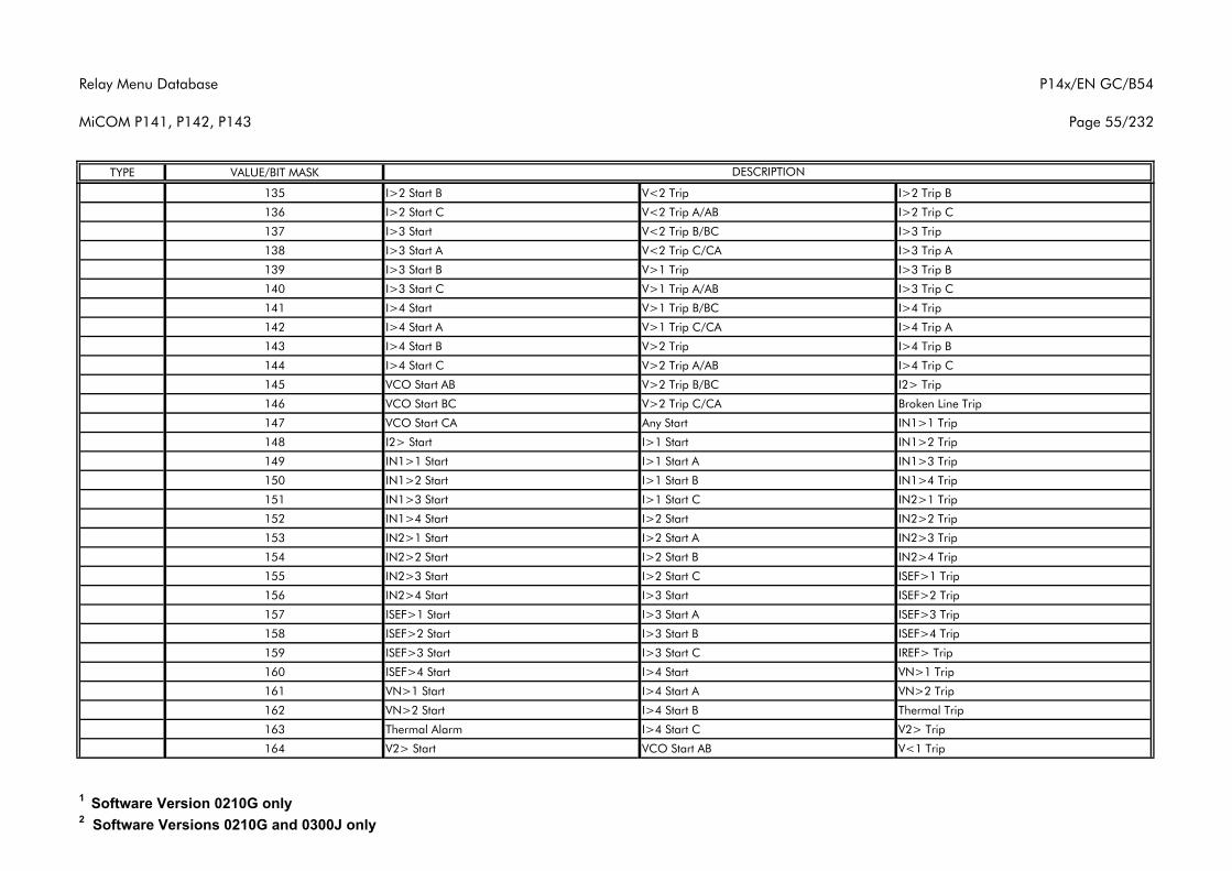
Relay Menu Database
MiCOM P141, P142, P143
P14x/EN GC/B54
Page 55/232
TYPE VALUE/BIT MASK DESCRIPTION
135 I>2 Start B V<2 Trip I>2 Trip B
136 I>2 Start C V<2 Trip A/AB I>2 Trip C
137 I>3 Start V<2 Trip B/BC I>3 Trip
138 I>3 Start A V<2 Trip C/CA I>3 Trip A
139 I>3 Start B V>1 Trip I>3 Trip B
140 I>3 Start C V>1 Trip A/AB I>3 Trip C
141 I>4 Start V>1 Trip B/BC I>4 Trip
142 I>4 Start A V>1 Trip C/CA I>4 Trip A
143 I>4 Start B V>2 Trip I>4 Trip B
144 I>4 Start C V>2 Trip A/AB I>4 Trip C
145 VCO Start AB V>2 Trip B/BC I2> Trip
146 VCO Start BC V>2 Trip C/CA Broken Line Trip
147 VCO Start CA Any Start IN1>1 Trip
148 I2> Start I>1 Start IN1>2 Trip
149 IN1>1 Start I>1 Start A IN1>3 Trip
150 IN1>2 Start I>1 Start B IN1>4 Trip
151 IN1>3 Start I>1 Start C IN2>1 Trip
152 IN1>4 Start I>2 Start IN2>2 Trip
153 IN2>1 Start I>2 Start A IN2>3 Trip
154 IN2>2 Start I>2 Start B IN2>4 Trip
155 IN2>3 Start I>2 Start C ISEF>1 Trip
156 IN2>4 Start I>3 Start ISEF>2 Trip
157 ISEF>1 Start I>3 Start A ISEF>3 Trip
158 ISEF>2 Start I>3 Start B ISEF>4 Trip
159 ISEF>3 Start I>3 Start C IREF> Trip
160 ISEF>4 Start I>4 Start VN>1 Trip
161 VN>1 Start I>4 Start A VN>2 Trip
162 VN>2 Start I>4 Start B Thermal Trip
163 Thermal Alarm I>4 Start C V2> Trip
164 V2> Start VCO Start AB V<1 Trip
1 Software Version 0210G only2 Software Versions 0210G and 0300J only
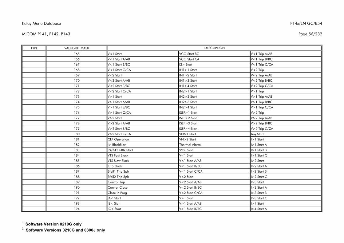
Relay Menu Database
MiCOM P141, P142, P143
P14x/EN GC/B54
Page 56/232
TYPE VALUE/BIT MASK DESCRIPTION
165 V<1 Start VCO Start BC V<1 Trip A/AB
166 V<1 Start A/AB VCO Start CA V<1 Trip B/BC
167 V<1 Start B/BC I2> Start V<1 Trip C/CA
168 V<1 Start C/CA IN1>1 Start V<2 Trip
169 V<2 Start IN1>2 Start V<2 Trip A/AB
170 V<2 Start A/AB IN1>3 Start V<2 Trip B/BC
171 V<2 Start B/BC IN1>4 Start V<2 Trip C/CA
172 V<2 Start C/CA IN2>1 Start V>1 Trip
173 V>1 Start IN2>2 Start V>1 Trip A/AB
174 V>1 Start A/AB IN2>3 Start V>1 Trip B/BC
175 V>1 Start B/BC IN2>4 Start V>1 Trip C/CA
176 V>1 Start C/CA ISEF>1 Start V>2 Trip
177 V>2 Start ISEF>2 Start V>2 Trip A/AB
178 V>2 Start A/AB ISEF>3 Start V>2 Trip B/BC
179 V>2 Start B/BC ISEF>4 Start V>2 Trip C/CA
180 V>2 Start C/CA VN>1 Start Any Start
181 CLP Operation VN>2 Start I>1 Start
182 I> BlockStart Thermal Alarm I>1 Start A
183 IN/ISEF>Blk Start V2> Start I>1 Start B
184 VTS Fast Block V<1 Start I>1 Start C
185 VTS Slow Block V<1 Start A/AB I>2 Start
186 CTS Block V<1 Start B/BC I>2 Start A
187 Bfail1 Trip 3ph V<1 Start C/CA I>2 Start B
188 Bfail2 Trip 3ph V<2 Start I>2 Start C
189 Control Trip V<2 Start A/AB I>3 Start
190 Control Close V<2 Start B/BC I>3 Start A
191 Close in Prog V<2 Start C/CA I>3 Start B
192 IA< Start V>1 Start I>3 Start C
193 IB< Start V>1 Start A/AB I>4 Start
194 IC< Start V>1 Start B/BC I>4 Start A
1 Software Version 0210G only2 Software Versions 0210G and 0300J only
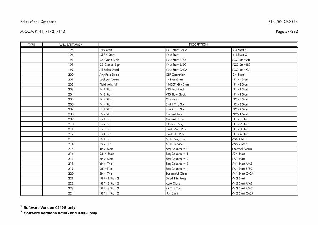
Relay Menu Database
MiCOM P141, P142, P143
P14x/EN GC/B54
Page 57/232
TYPE VALUE/BIT MASK DESCRIPTION
195 IN< Start V>1 Start C/CA I>4 Start B
196 ISEF< Start V>2 Start I>4 Start C
197 CB Open 3 ph V>2 Start A/AB VCO Start AB
198 CB Closed 3 ph V>2 Start B/BC VCO Start BC
199 All Poles Dead V>2 Start C/CA VCO Start CA
200 Any Pole Dead CLP Operation I2> Start
201 Lockout Alarm I> BlockStart IN1>1 Start
202 Field volts fail IN/ISEF>Blk Start IN1>2 Start
203 F<1 Start VTS Fast Block IN1>3 Start
204 F<2 Start VTS Slow Block IN1>4 Start
205 F<3 Start CTS Block IN2>1 Start
206 F<4 Start Bfail1 Trip 3ph IN2>2 Start
207 F>1 Start Bfail2 Trip 3ph IN2>3 Start
208 F>2 Start Control Trip IN2>4 Start
209 F<1 Trip Control Close ISEF>1 Start
210 F<2 Trip Close in Prog ISEF>2 Start
211 F<3 Trip Block Main Prot ISEF>3 Start
212 F<4 Trip Block SEF Prot ISEF>4 Start
213 F>1 Trip AR In Progress VN>1 Start
214 F>2 Trip AR In Service VN>2 Start
215 YN> Start Seq Counter = 0 Thermal Alarm
216 GN> Start Seq Counter = 1 V2> Start
217 BN> Start Seq Counter = 2 V<1 Start
218 YN> Trip Seq Counter = 3 V<1 Start A/AB
219 GN>Trip Seq Counter = 4 V<1 Start B/BC
220 BN> Trip Successful Close V<1 Start C/CA
221 ISEF>1 Start 2 Dead T in Prog V<2 Start
222 ISEF>2 Start 2 Auto Close V<2 Start A/AB
223 ISEF>3 Start 2 AR Trip Test V<2 Start B/BC
224 ISEF>4 Start 2 IA< Start V<2 Start C/CA
1 Software Version 0210G only2 Software Versions 0210G and 0300J only
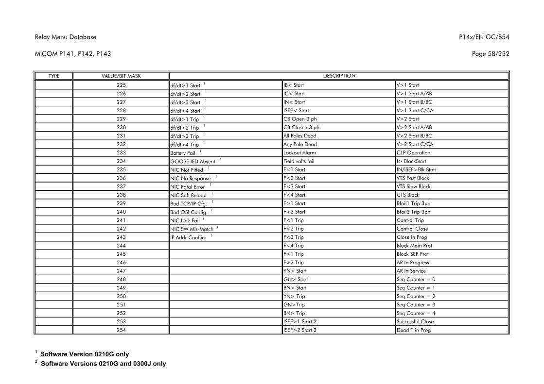
Relay Menu Database
MiCOM P141, P142, P143
P14x/EN GC/B54
Page 58/232
TYPE VALUE/BIT MASK DESCRIPTION
225 df/dt>1 Start 1 IB< Start V>1 Start
226 df/dt>2 Start 1 IC< Start V>1 Start A/AB
227 df/dt>3 Start 1 IN< Start V>1 Start B/BC
228 df/dt>4 Start 1 ISEF< Start V>1 Start C/CA
229 df/dt>1 Trip 1 CB Open 3 ph V>2 Start
230 df/dt>2 Trip 1 CB Closed 3 ph V>2 Start A/AB
231 df/dt>3 Trip 1 All Poles Dead V>2 Start B/BC
232 df/dt>4 Trip 1 Any Pole Dead V>2 Start C/CA
233 Battery Fail 1 Lockout Alarm CLP Operation
234 GOOSE IED Absent 1 Field volts fail I> BlockStart
235 NIC Not Fitted 1 F<1 Start IN/ISEF>Blk Start
236 NIC No Response 1 F<2 Start VTS Fast Block
237 NIC Fatal Error 1 F<3 Start VTS Slow Block
238 NIC Soft Reload 1 F<4 Start CTS Block
239 Bad TCP/IP Cfg. 1 F>1 Start Bfail1 Trip 3ph
240 Bad OSI Config. 1 F>2 Start Bfail2 Trip 3ph
241 NIC Link Fail 1 F<1 Trip Control Trip
242 NIC SW Mis-Match 1 F<2 Trip Control Close
243 IP Addr Conflict 1 F<3 Trip Close in Prog
244 F<4 Trip Block Main Prot
245 F>1 Trip Block SEF Prot
246 F>2 Trip AR In Progress
247 YN> Start AR In Service
248 GN> Start Seq Counter = 0
249 BN> Start Seq Counter = 1
250 YN> Trip Seq Counter = 2
251 GN>Trip Seq Counter = 3
252 BN> Trip Seq Counter = 4
253 ISEF>1 Start 2 Successful Close
254 ISEF>2 Start 2 Dead T in Prog
1 Software Version 0210G only2 Software Versions 0210G and 0300J only
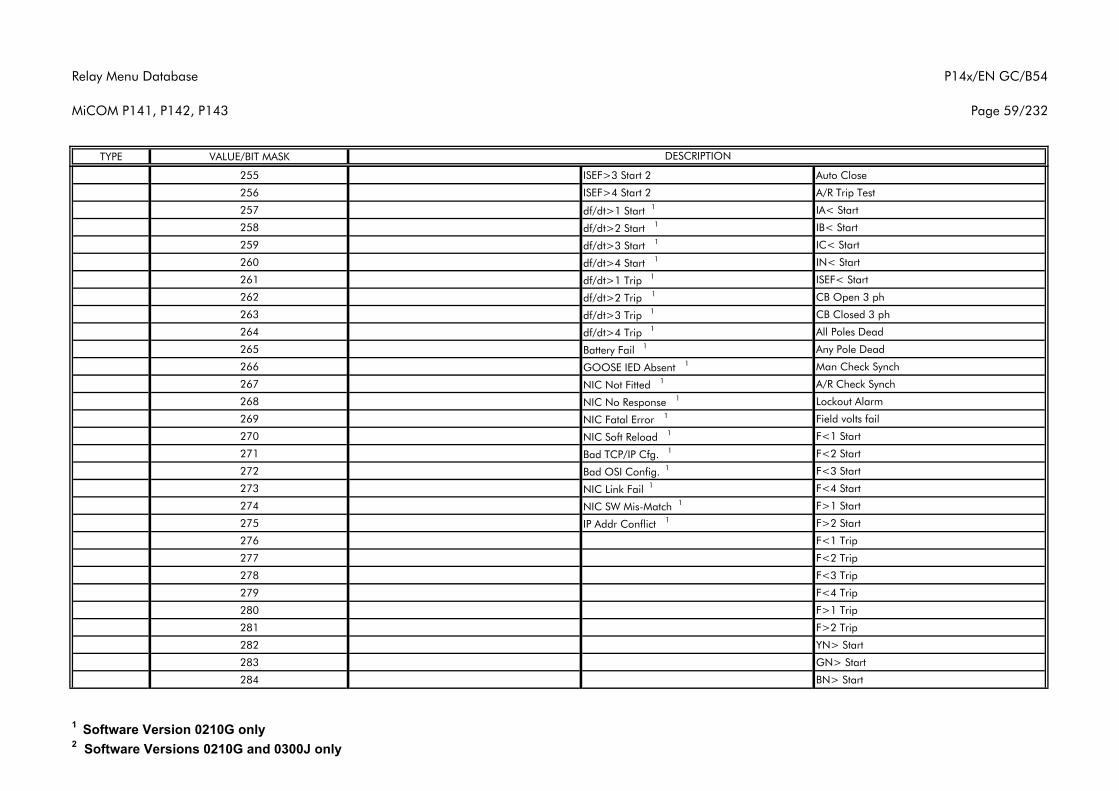
Relay Menu Database
MiCOM P141, P142, P143
P14x/EN GC/B54
Page 59/232
TYPE VALUE/BIT MASK DESCRIPTION
255 ISEF>3 Start 2 Auto Close
256 ISEF>4 Start 2 A/R Trip Test
257 df/dt>1 Start 1 IA< Start
258 df/dt>2 Start 1 IB< Start
259 df/dt>3 Start 1 IC< Start
260 df/dt>4 Start 1 IN< Start
261 df/dt>1 Trip 1 ISEF< Start
262 df/dt>2 Trip 1 CB Open 3 ph
263 df/dt>3 Trip 1 CB Closed 3 ph
264 df/dt>4 Trip 1 All Poles Dead
265 Battery Fail 1 Any Pole Dead
266 GOOSE IED Absent 1 Man Check Synch
267 NIC Not Fitted 1 A/R Check Synch
268 NIC No Response 1 Lockout Alarm
269 NIC Fatal Error 1 Field volts fail
270 NIC Soft Reload 1 F<1 Start
271 Bad TCP/IP Cfg. 1 F<2 Start
272 Bad OSI Config. 1 F<3 Start
273 NIC Link Fail 1 F<4 Start
274 NIC SW Mis-Match 1 F>1 Start
275 IP Addr Conflict 1 F>2 Start
276 F<1 Trip
277 F<2 Trip
278 F<3 Trip
279 F<4 Trip
280 F>1 Trip
281 F>2 Trip
282 YN> Start
283 GN> Start
284 BN> Start
1 Software Version 0210G only2 Software Versions 0210G and 0300J only
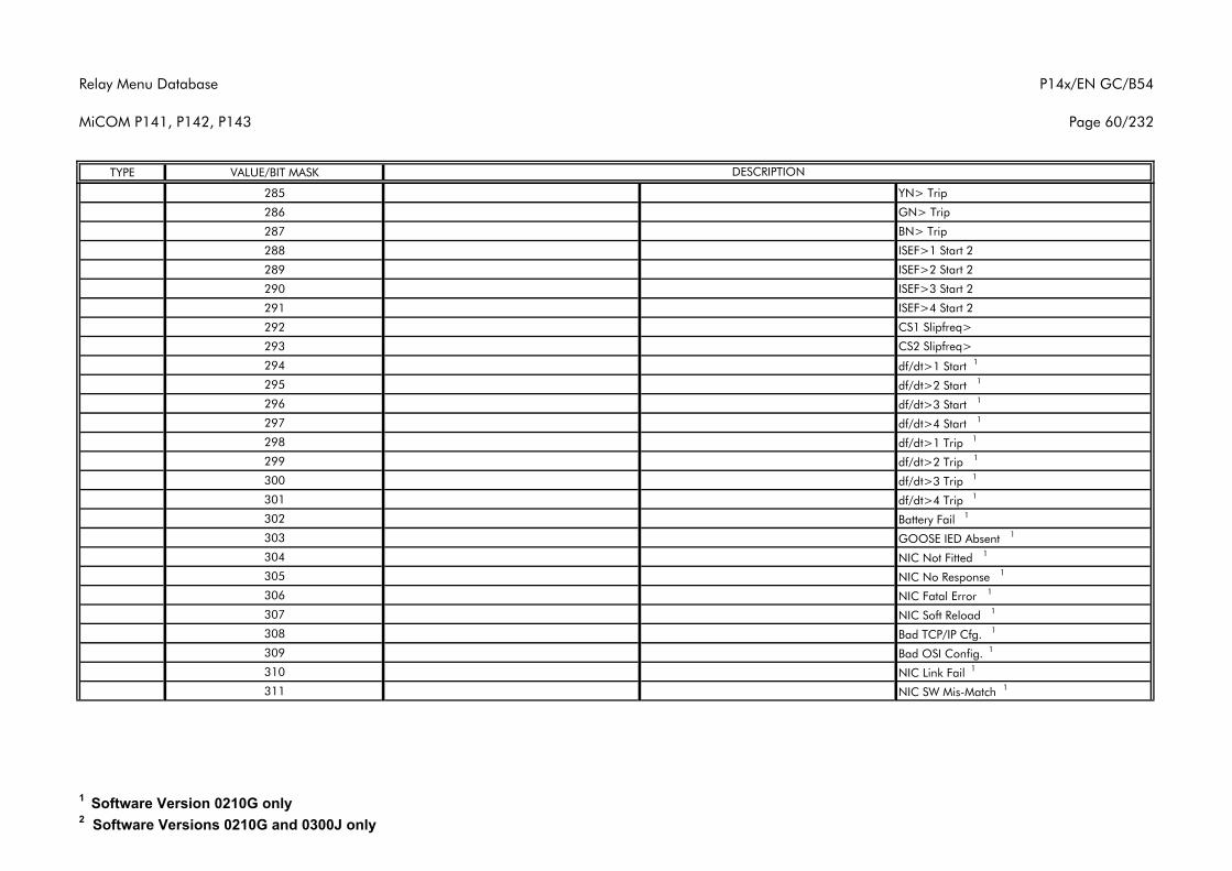
Relay Menu Database
MiCOM P141, P142, P143
P14x/EN GC/B54
Page 60/232
TYPE VALUE/BIT MASK DESCRIPTION
285 YN> Trip
286 GN> Trip
287 BN> Trip
288 ISEF>1 Start 2
289 ISEF>2 Start 2
290 ISEF>3 Start 2
291 ISEF>4 Start 2
292 CS1 Slipfreq>
293 CS2 Slipfreq>
294 df/dt>1 Start 1
295 df/dt>2 Start 1
296 df/dt>3 Start 1
297 df/dt>4 Start 1
298 df/dt>1 Trip 1
299 df/dt>2 Trip 1
300 df/dt>3 Trip 1
301 df/dt>4 Trip 1
302 Battery Fail 1
303 GOOSE IED Absent 1
304 NIC Not Fitted 1
305 NIC No Response 1
306 NIC Fatal Error 1
307 NIC Soft Reload 1
308 Bad TCP/IP Cfg. 1
309 Bad OSI Config. 1
310 NIC Link Fail 1
311 NIC SW Mis-Match 1
1 Software Version 0210G only2 Software Versions 0210G and 0300J only
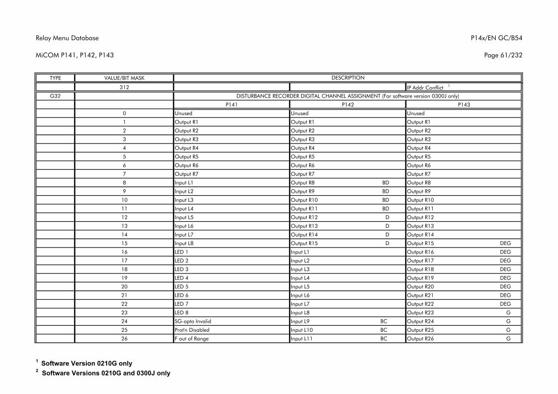
Relay Menu Database
MiCOM P141, P142, P143
P14x/EN GC/B54
Page 61/232
TYPE VALUE/BIT MASK DESCRIPTION
312 IP Addr Conflict 1
G32
P141 P142 P143
0 Unused Unused Unused
1 Output R1 Output R1 Output R1
2 Output R2 Output R2 Output R2
3 Output R3 Output R3 Output R3
4 Output R4 Output R4 Output R4
5 Output R5 Output R5 Output R5
6 Output R6 Output R6 Output R6
7 Output R7 Output R7 Output R7
8 Input L1 Output R8 BD Output R8
9 Input L2 Output R9 BD Output R9
10 Input L3 Output R10 BD Output R10
11 Input L4 Output R11 BD Output R11
12 Input L5 Output R12 D Output R12
13 Input L6 Output R13 D Output R13
14 Input L7 Output R14 D Output R14
15 Input L8 Output R15 D Output R15 DEG
16 LED 1 Input L1 Output R16 DEG
17 LED 2 Input L2 Output R17 DEG
18 LED 3 Input L3 Output R18 DEG
19 LED 4 Input L4 Output R19 DEG
20 LED 5 Input L5 Output R20 DEG
21 LED 6 Input L6 Output R21 DEG
22 LED 7 Input L7 Output R22 DEG
23 LED 8 Input L8 Output R23 G
24 SG-opto Invalid Input L9 BC Output R24 G
25 Prot'n Disabled Input L10 BC Output R25 G
26 F out of Range Input L11 BC Output R26 G
DISTURBANCE RECORDER DIGITAL CHANNEL ASSIGNMENT (For software version 0300J only)
1 Software Version 0210G only2 Software Versions 0210G and 0300J only
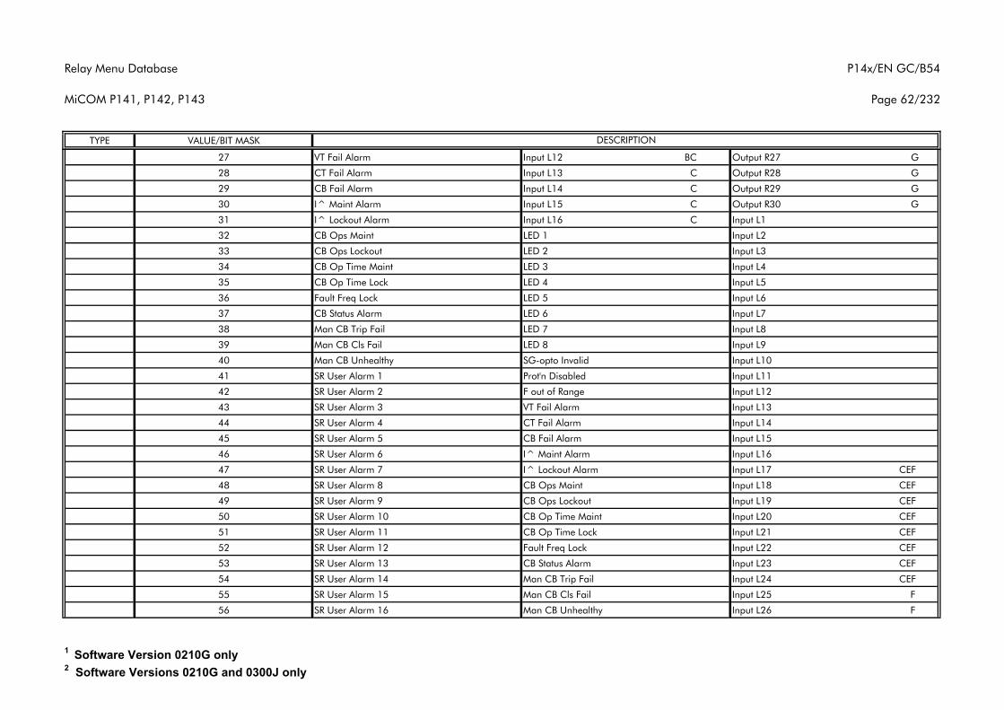
Relay Menu Database
MiCOM P141, P142, P143
P14x/EN GC/B54
Page 62/232
TYPE VALUE/BIT MASK DESCRIPTION
27 VT Fail Alarm Input L12 BC Output R27 G
28 CT Fail Alarm Input L13 C Output R28 G
29 CB Fail Alarm Input L14 C Output R29 G
30 I^ Maint Alarm Input L15 C Output R30 G
31 I^ Lockout Alarm Input L16 C Input L1
32 CB Ops Maint LED 1 Input L2
33 CB Ops Lockout LED 2 Input L3
34 CB Op Time Maint LED 3 Input L4
35 CB Op Time Lock LED 4 Input L5
36 Fault Freq Lock LED 5 Input L6
37 CB Status Alarm LED 6 Input L7
38 Man CB Trip Fail LED 7 Input L8
39 Man CB Cls Fail LED 8 Input L9
40 Man CB Unhealthy SG-opto Invalid Input L10
41 SR User Alarm 1 Prot'n Disabled Input L11
42 SR User Alarm 2 F out of Range Input L12
43 SR User Alarm 3 VT Fail Alarm Input L13
44 SR User Alarm 4 CT Fail Alarm Input L14
45 SR User Alarm 5 CB Fail Alarm Input L15
46 SR User Alarm 6 I^ Maint Alarm Input L16
47 SR User Alarm 7 I^ Lockout Alarm Input L17 CEF
48 SR User Alarm 8 CB Ops Maint Input L18 CEF
49 SR User Alarm 9 CB Ops Lockout Input L19 CEF
50 SR User Alarm 10 CB Op Time Maint Input L20 CEF
51 SR User Alarm 11 CB Op Time Lock Input L21 CEF
52 SR User Alarm 12 Fault Freq Lock Input L22 CEF
53 SR User Alarm 13 CB Status Alarm Input L23 CEF
54 SR User Alarm 14 Man CB Trip Fail Input L24 CEF
55 SR User Alarm 15 Man CB Cls Fail Input L25 F
56 SR User Alarm 16 Man CB Unhealthy Input L26 F
1 Software Version 0210G only2 Software Versions 0210G and 0300J only
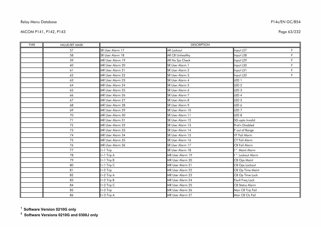
Relay Menu Database
MiCOM P141, P142, P143
P14x/EN GC/B54
Page 63/232
TYPE VALUE/BIT MASK DESCRIPTION
57 SR User Alarm 17 AR Lockout Input L27 F
58 SR User Alarm 18 AR CB Unhealthy Input L28 F
59 MR User Alarm 19 AR No Sys Check Input L29 F
60 MR User Alarm 20 SR User Alarm 1 Input L30 F
61 MR User Alarm 21 SR User Alarm 2 Input L31 F
62 MR User Alarm 22 SR User Alarm 3 Input L32 F
63 MR User Alarm 23 SR User Alarm 4 LED 1
64 MR User Alarm 24 SR User Alarm 5 LED 2
65 MR User Alarm 25 SR User Alarm 6 LED 3
66 MR User Alarm 26 SR User Alarm 7 LED 4
67 MR User Alarm 27 SR User Alarm 8 LED 5
68 MR User Alarm 28 SR User Alarm 9 LED 6
69 MR User Alarm 29 SR User Alarm 10 LED 7
70 MR User Alarm 30 SR User Alarm 11 LED 8
71 MR User Alarm 31 SR User Alarm 12 SG-opto Invalid
72 MR User Alarm 32 SR User Alarm 13 Prot'n Disabled
73 MR User Alarm 33 SR User Alarm 14 F out of Range
74 MR User Alarm 34 SR User Alarm 15 VT Fail Alarm
75 MR User Alarm 35 SR User Alarm 16 CT Fail Alarm
76 MR User Alarm 36 SR User Alarm 17 CB Fail Alarm
77 I>1 Trip SR User Alarm 18 I^ Maint Alarm
78 I>1 Trip A MR User Alarm 19 I^ Lockout Alarm
79 I>1 Trip B MR User Alarm 20 CB Ops Maint
80 I>1 Trip C MR User Alarm 21 CB Ops Lockout
81 I>2 Trip MR User Alarm 22 CB Op Time Maint
82 I>2 Trip A MR User Alarm 23 CB Op Time Lock
83 I>2 Trip B MR User Alarm 24 Fault Freq Lock
84 I>2 Trip C MR User Alarm 25 CB Status Alarm
85 I>3 Trip MR User Alarm 26 Man CB Trip Fail
86 I>3 Trip A MR User Alarm 27 Man CB Cls Fail
1 Software Version 0210G only2 Software Versions 0210G and 0300J only
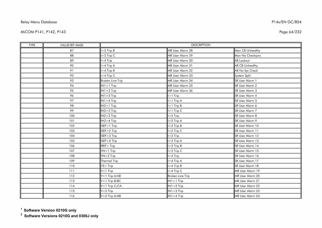
Relay Menu Database
MiCOM P141, P142, P143
P14x/EN GC/B54
Page 64/232
TYPE VALUE/BIT MASK DESCRIPTION
87 I>3 Trip B MR User Alarm 28 Man CB Unhealthy
88 I>3 Trip C MR User Alarm 29 Man No Checksync
89 I>4 Trip MR User Alarm 30 AR Lockout
90 I>4 Trip A MR User Alarm 31 AR CB Unhealthy
91 I>4 Trip B MR User Alarm 32 AR No Sys Check
92 I>4 Trip C MR User Alarm 33 System Split
93 Broken Line Trip MR User Alarm 34 SR User Alarm 1
94 IN1>1 Trip MR User Alarm 35 SR User Alarm 2
95 IN1>2 Trip MR User Alarm 36 SR User Alarm 3
96 IN1>3 Trip I>1 Trip SR User Alarm 4
97 IN1>4 Trip I>1 Trip A SR User Alarm 5
98 IN2>1 Trip I>1 Trip B SR User Alarm 6
99 IN2>2 Trip I>1 Trip C SR User Alarm 7
100 IN2>3 Trip I>2 Trip SR User Alarm 8
101 IN2>4 Trip I>2 Trip A SR User Alarm 9
102 ISEF>1 Trip I>2 Trip B SR User Alarm 10
103 ISEF>2 Trip I>2 Trip C SR User Alarm 11
104 ISEF>3 Trip I>3 Trip SR User Alarm 12
105 ISEF>4 Trip I>3 Trip A SR User Alarm 13
106 IREF> Trip I>3 Trip B SR User Alarm 14
107 VN>1 Trip I>3 Trip C SR User Alarm 15
108 VN>2 Trip I>4 Trip SR User Alarm 16
109 Thermal Trip I>4 Trip A SR User Alarm 17
110 V2> Trip I>4 Trip B SR User Alarm 18
111 V<1 Trip I>4 Trip C MR User Alarm 19
112 V<1 Trip A/AB Broken Line Trip MR User Alarm 20
113 V<1 Trip B/BC IN1>1 Trip MR User Alarm 21
114 V<1 Trip C/CA IN1>2 Trip MR User Alarm 22
115 V<2 Trip IN1>3 Trip MR User Alarm 23
116 V<2 Trip A/AB IN1>4 Trip MR User Alarm 24
1 Software Version 0210G only2 Software Versions 0210G and 0300J only
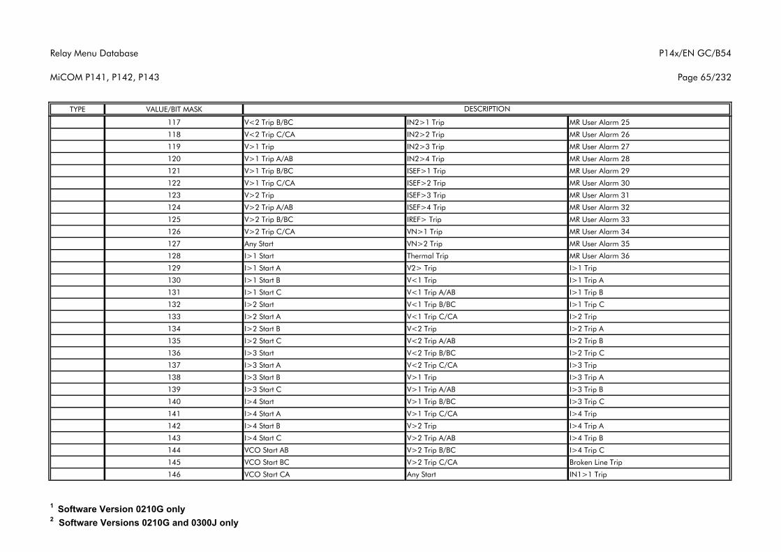
Relay Menu Database
MiCOM P141, P142, P143
P14x/EN GC/B54
Page 65/232
TYPE VALUE/BIT MASK DESCRIPTION
117 V<2 Trip B/BC IN2>1 Trip MR User Alarm 25
118 V<2 Trip C/CA IN2>2 Trip MR User Alarm 26
119 V>1 Trip IN2>3 Trip MR User Alarm 27
120 V>1 Trip A/AB IN2>4 Trip MR User Alarm 28
121 V>1 Trip B/BC ISEF>1 Trip MR User Alarm 29
122 V>1 Trip C/CA ISEF>2 Trip MR User Alarm 30
123 V>2 Trip ISEF>3 Trip MR User Alarm 31
124 V>2 Trip A/AB ISEF>4 Trip MR User Alarm 32
125 V>2 Trip B/BC IREF> Trip MR User Alarm 33
126 V>2 Trip C/CA VN>1 Trip MR User Alarm 34
127 Any Start VN>2 Trip MR User Alarm 35
128 I>1 Start Thermal Trip MR User Alarm 36
129 I>1 Start A V2> Trip I>1 Trip
130 I>1 Start B V<1 Trip I>1 Trip A
131 I>1 Start C V<1 Trip A/AB I>1 Trip B
132 I>2 Start V<1 Trip B/BC I>1 Trip C
133 I>2 Start A V<1 Trip C/CA I>2 Trip
134 I>2 Start B V<2 Trip I>2 Trip A
135 I>2 Start C V<2 Trip A/AB I>2 Trip B
136 I>3 Start V<2 Trip B/BC I>2 Trip C
137 I>3 Start A V<2 Trip C/CA I>3 Trip
138 I>3 Start B V>1 Trip I>3 Trip A
139 I>3 Start C V>1 Trip A/AB I>3 Trip B
140 I>4 Start V>1 Trip B/BC I>3 Trip C
141 I>4 Start A V>1 Trip C/CA I>4 Trip
142 I>4 Start B V>2 Trip I>4 Trip A
143 I>4 Start C V>2 Trip A/AB I>4 Trip B
144 VCO Start AB V>2 Trip B/BC I>4 Trip C
145 VCO Start BC V>2 Trip C/CA Broken Line Trip
146 VCO Start CA Any Start IN1>1 Trip
1 Software Version 0210G only2 Software Versions 0210G and 0300J only
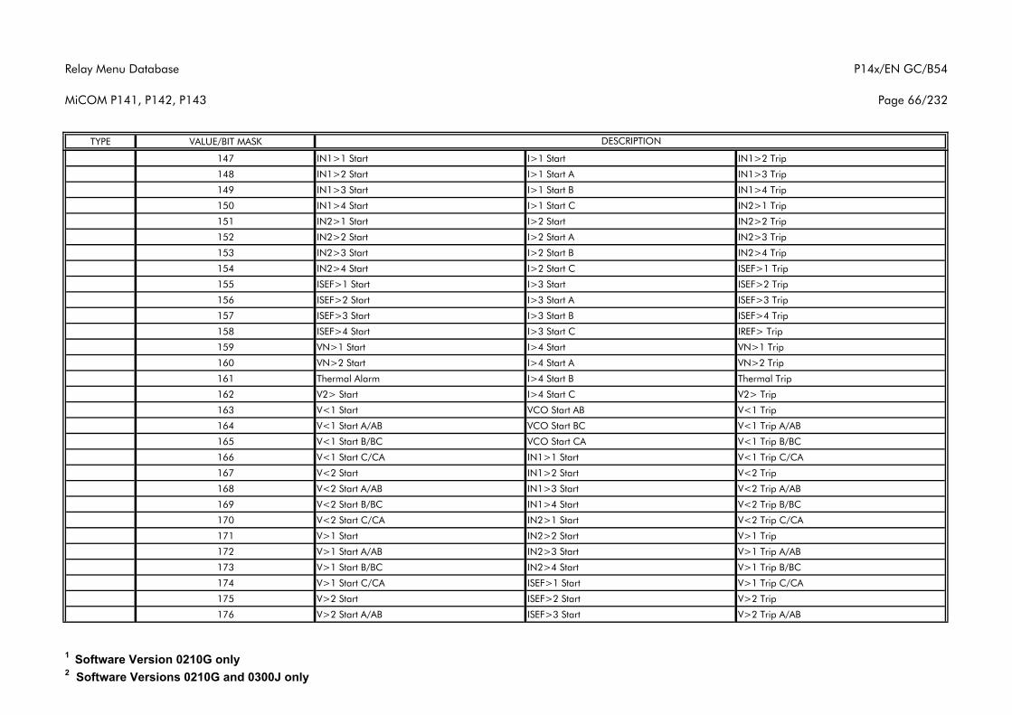
Relay Menu Database
MiCOM P141, P142, P143
P14x/EN GC/B54
Page 66/232
TYPE VALUE/BIT MASK DESCRIPTION
147 IN1>1 Start I>1 Start IN1>2 Trip
148 IN1>2 Start I>1 Start A IN1>3 Trip
149 IN1>3 Start I>1 Start B IN1>4 Trip
150 IN1>4 Start I>1 Start C IN2>1 Trip
151 IN2>1 Start I>2 Start IN2>2 Trip
152 IN2>2 Start I>2 Start A IN2>3 Trip
153 IN2>3 Start I>2 Start B IN2>4 Trip
154 IN2>4 Start I>2 Start C ISEF>1 Trip
155 ISEF>1 Start I>3 Start ISEF>2 Trip
156 ISEF>2 Start I>3 Start A ISEF>3 Trip
157 ISEF>3 Start I>3 Start B ISEF>4 Trip
158 ISEF>4 Start I>3 Start C IREF> Trip
159 VN>1 Start I>4 Start VN>1 Trip
160 VN>2 Start I>4 Start A VN>2 Trip
161 Thermal Alarm I>4 Start B Thermal Trip
162 V2> Start I>4 Start C V2> Trip
163 V<1 Start VCO Start AB V<1 Trip
164 V<1 Start A/AB VCO Start BC V<1 Trip A/AB
165 V<1 Start B/BC VCO Start CA V<1 Trip B/BC
166 V<1 Start C/CA IN1>1 Start V<1 Trip C/CA
167 V<2 Start IN1>2 Start V<2 Trip
168 V<2 Start A/AB IN1>3 Start V<2 Trip A/AB
169 V<2 Start B/BC IN1>4 Start V<2 Trip B/BC
170 V<2 Start C/CA IN2>1 Start V<2 Trip C/CA
171 V>1 Start IN2>2 Start V>1 Trip
172 V>1 Start A/AB IN2>3 Start V>1 Trip A/AB
173 V>1 Start B/BC IN2>4 Start V>1 Trip B/BC
174 V>1 Start C/CA ISEF>1 Start V>1 Trip C/CA
175 V>2 Start ISEF>2 Start V>2 Trip
176 V>2 Start A/AB ISEF>3 Start V>2 Trip A/AB
1 Software Version 0210G only2 Software Versions 0210G and 0300J only
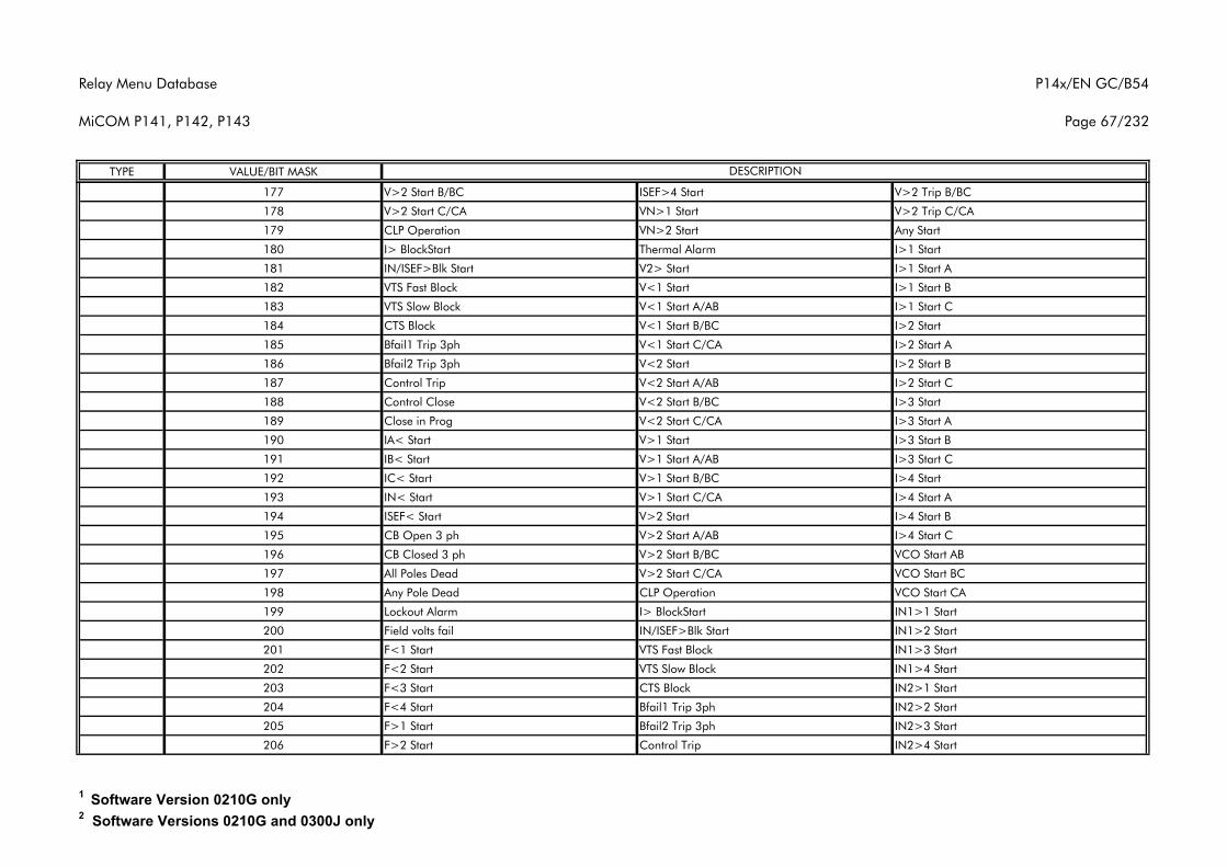
Relay Menu Database
MiCOM P141, P142, P143
P14x/EN GC/B54
Page 67/232
TYPE VALUE/BIT MASK DESCRIPTION
177 V>2 Start B/BC ISEF>4 Start V>2 Trip B/BC
178 V>2 Start C/CA VN>1 Start V>2 Trip C/CA
179 CLP Operation VN>2 Start Any Start
180 I> BlockStart Thermal Alarm I>1 Start
181 IN/ISEF>Blk Start V2> Start I>1 Start A
182 VTS Fast Block V<1 Start I>1 Start B
183 VTS Slow Block V<1 Start A/AB I>1 Start C
184 CTS Block V<1 Start B/BC I>2 Start
185 Bfail1 Trip 3ph V<1 Start C/CA I>2 Start A
186 Bfail2 Trip 3ph V<2 Start I>2 Start B
187 Control Trip V<2 Start A/AB I>2 Start C
188 Control Close V<2 Start B/BC I>3 Start
189 Close in Prog V<2 Start C/CA I>3 Start A
190 IA< Start V>1 Start I>3 Start B
191 IB< Start V>1 Start A/AB I>3 Start C
192 IC< Start V>1 Start B/BC I>4 Start
193 IN< Start V>1 Start C/CA I>4 Start A
194 ISEF< Start V>2 Start I>4 Start B
195 CB Open 3 ph V>2 Start A/AB I>4 Start C
196 CB Closed 3 ph V>2 Start B/BC VCO Start AB
197 All Poles Dead V>2 Start C/CA VCO Start BC
198 Any Pole Dead CLP Operation VCO Start CA
199 Lockout Alarm I> BlockStart IN1>1 Start
200 Field volts fail IN/ISEF>Blk Start IN1>2 Start
201 F<1 Start VTS Fast Block IN1>3 Start
202 F<2 Start VTS Slow Block IN1>4 Start
203 F<3 Start CTS Block IN2>1 Start
204 F<4 Start Bfail1 Trip 3ph IN2>2 Start
205 F>1 Start Bfail2 Trip 3ph IN2>3 Start
206 F>2 Start Control Trip IN2>4 Start
1 Software Version 0210G only2 Software Versions 0210G and 0300J only
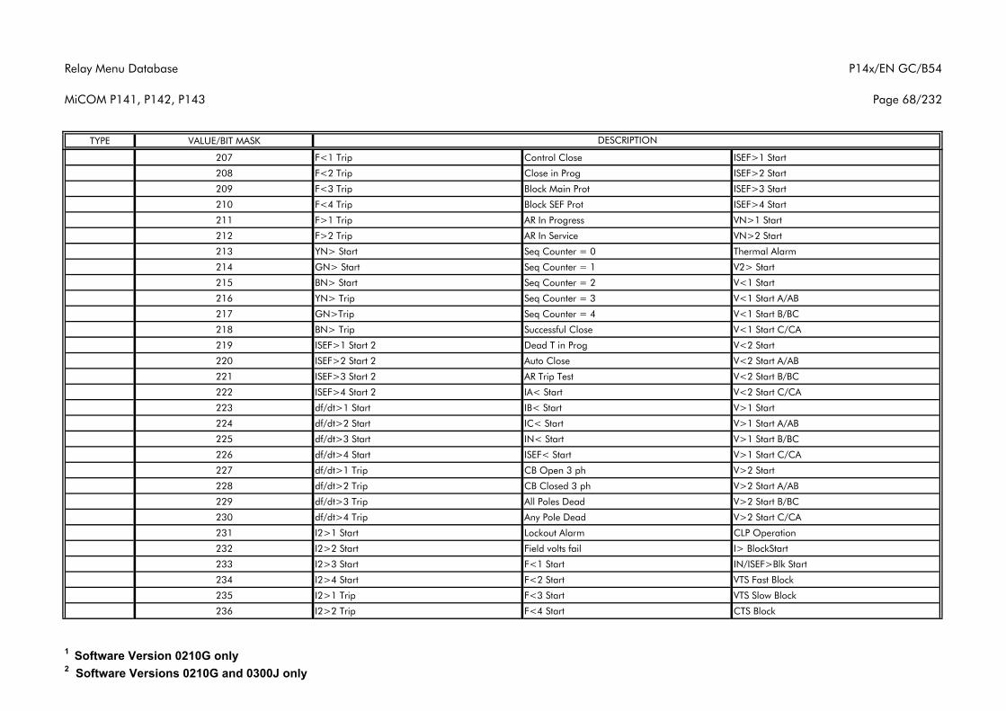
Relay Menu Database
MiCOM P141, P142, P143
P14x/EN GC/B54
Page 68/232
TYPE VALUE/BIT MASK DESCRIPTION
207 F<1 Trip Control Close ISEF>1 Start
208 F<2 Trip Close in Prog ISEF>2 Start
209 F<3 Trip Block Main Prot ISEF>3 Start
210 F<4 Trip Block SEF Prot ISEF>4 Start
211 F>1 Trip AR In Progress VN>1 Start
212 F>2 Trip AR In Service VN>2 Start
213 YN> Start Seq Counter = 0 Thermal Alarm
214 GN> Start Seq Counter = 1 V2> Start
215 BN> Start Seq Counter = 2 V<1 Start
216 YN> Trip Seq Counter = 3 V<1 Start A/AB
217 GN>Trip Seq Counter = 4 V<1 Start B/BC
218 BN> Trip Successful Close V<1 Start C/CA
219 ISEF>1 Start 2 Dead T in Prog V<2 Start
220 ISEF>2 Start 2 Auto Close V<2 Start A/AB
221 ISEF>3 Start 2 AR Trip Test V<2 Start B/BC
222 ISEF>4 Start 2 IA< Start V<2 Start C/CA
223 df/dt>1 Start IB< Start V>1 Start
224 df/dt>2 Start IC< Start V>1 Start A/AB
225 df/dt>3 Start IN< Start V>1 Start B/BC
226 df/dt>4 Start ISEF< Start V>1 Start C/CA
227 df/dt>1 Trip CB Open 3 ph V>2 Start
228 df/dt>2 Trip CB Closed 3 ph V>2 Start A/AB
229 df/dt>3 Trip All Poles Dead V>2 Start B/BC
230 df/dt>4 Trip Any Pole Dead V>2 Start C/CA
231 I2>1 Start Lockout Alarm CLP Operation
232 I2>2 Start Field volts fail I> BlockStart
233 I2>3 Start F<1 Start IN/ISEF>Blk Start
234 I2>4 Start F<2 Start VTS Fast Block
235 I2>1 Trip F<3 Start VTS Slow Block
236 I2>2 Trip F<4 Start CTS Block
1 Software Version 0210G only2 Software Versions 0210G and 0300J only
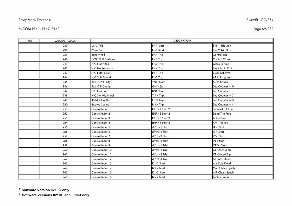
Relay Menu Database
MiCOM P141, P142, P143
P14x/EN GC/B54
Page 69/232
TYPE VALUE/BIT MASK DESCRIPTION
237 I2>3 Trip F>1 Start Bfail1 Trip 3ph
238 I2>4 Trip F>2 Start Bfail2 Trip 3ph
239 Battery Fail F<1 Trip Control Trip
240 GOOSE IED Absent F<2 Trip Control Close
241 NIC Not Fitted F<3 Trip Close in Prog
242 NIC No Response F<4 Trip Block Main Prot
243 NIC Fatal Error F>1 Trip Block SEF Prot
244 NIC Soft Reload F>2 Trip AR In Progress
245 Bad TCP/IP Cfg. YN> Start AR In Service
246 Bad OSI Config. GN> Start Seq Counter = 0
247 NIC Link Fail BN> Start Seq Counter = 1
248 NIC SW Mis-Match YN> Trip Seq Counter = 2
249 IP Addr Conflict GN>Trip Seq Counter = 3
250 Backup Setting BN> Trip Seq Counter = 4
251 Control Input 1 ISEF>1 Start 2 Successful Close
252 Control Input 2 ISEF>2 Start 2 Dead T in Prog
253 Control Input 3 ISEF>3 Start 2 Auto Close
254 Control Input 4 ISEF>4 Start 2 A/R Trip Test
255 Control Input 5 df/dt>1 Start IA< Start
256 Control Input 6 df/dt>2 Start IB< Start
257 Control Input 7 df/dt>3 Start IC< Start
258 Control Input 8 df/dt>4 Start IN< Start
259 Control Input 9 df/dt>1 Trip ISEF< Start
260 Control Input 10 df/dt>2 Trip CB Open 3 ph
261 Control Input 11 df/dt>3 Trip CB Closed 3 ph
262 Control Input 12 df/dt>4 Trip All Poles Dead
263 Control Input 13 I2>1 Start Any Pole Dead
264 Control Input 14 I2>2 Start Man Check Synch
265 Control Input 15 I2>3 Start A/R Check Synch
266 Control Input 16 I2>4 Start Lockout Alarm
1 Software Version 0210G only2 Software Versions 0210G and 0300J only
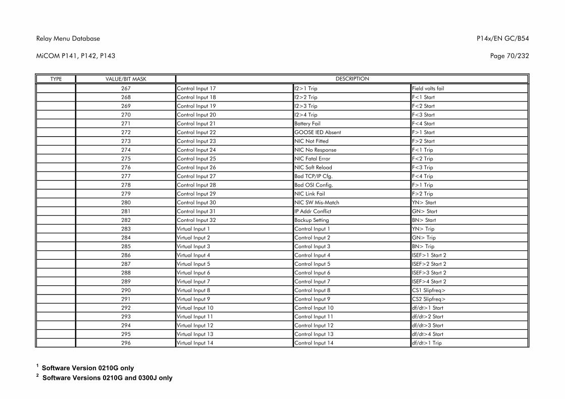
Relay Menu Database
MiCOM P141, P142, P143
P14x/EN GC/B54
Page 70/232
TYPE VALUE/BIT MASK DESCRIPTION
267 Control Input 17 I2>1 Trip Field volts fail
268 Control Input 18 I2>2 Trip F<1 Start
269 Control Input 19 I2>3 Trip F<2 Start
270 Control Input 20 I2>4 Trip F<3 Start
271 Control Input 21 Battery Fail F<4 Start
272 Control Input 22 GOOSE IED Absent F>1 Start
273 Control Input 23 NIC Not Fitted F>2 Start
274 Control Input 24 NIC No Response F<1 Trip
275 Control Input 25 NIC Fatal Error F<2 Trip
276 Control Input 26 NIC Soft Reload F<3 Trip
277 Control Input 27 Bad TCP/IP Cfg. F<4 Trip
278 Control Input 28 Bad OSI Config. F>1 Trip
279 Control Input 29 NIC Link Fail F>2 Trip
280 Control Input 30 NIC SW Mis-Match YN> Start
281 Control Input 31 IP Addr Conflict GN> Start
282 Control Input 32 Backup Setting BN> Start
283 Virtual Input 1 Control Input 1 YN> Trip
284 Virtual Input 2 Control Input 2 GN> Trip
285 Virtual Input 3 Control Input 3 BN> Trip
286 Virtual Input 4 Control Input 4 ISEF>1 Start 2
287 Virtual Input 5 Control Input 5 ISEF>2 Start 2
288 Virtual Input 6 Control Input 6 ISEF>3 Start 2
289 Virtual Input 7 Control Input 7 ISEF>4 Start 2
290 Virtual Input 8 Control Input 8 CS1 Slipfreq>
291 Virtual Input 9 Control Input 9 CS2 Slipfreq>
292 Virtual Input 10 Control Input 10 df/dt>1 Start
293 Virtual Input 11 Control Input 11 df/dt>2 Start
294 Virtual Input 12 Control Input 12 df/dt>3 Start
295 Virtual Input 13 Control Input 13 df/dt>4 Start
296 Virtual Input 14 Control Input 14 df/dt>1 Trip
1 Software Version 0210G only2 Software Versions 0210G and 0300J only
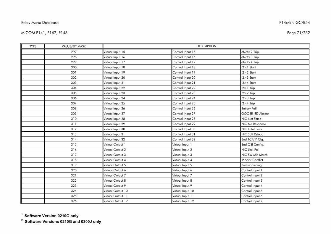
Relay Menu Database
MiCOM P141, P142, P143
P14x/EN GC/B54
Page 71/232
TYPE VALUE/BIT MASK DESCRIPTION
297 Virtual Input 15 Control Input 15 df/dt>2 Trip
298 Virtual Input 16 Control Input 16 df/dt>3 Trip
299 Virtual Input 17 Control Input 17 df/dt>4 Trip
300 Virtual Input 18 Control Input 18 I2>1 Start
301 Virtual Input 19 Control Input 19 I2>2 Start
302 Virtual Input 20 Control Input 20 I2>3 Start
303 Virtual Input 21 Control Input 21 I2>4 Start
304 Virtual Input 22 Control Input 22 I2>1 Trip
305 Virtual Input 23 Control Input 23 I2>2 Trip
306 Virtual Input 24 Control Input 24 I2>3 Trip
307 Virtual Input 25 Control Input 25 I2>4 Trip
308 Virtual Input 26 Control Input 26 Battery Fail
309 Virtual Input 27 Control Input 27 GOOSE IED Absent
310 Virtual Input 28 Control Input 28 NIC Not Fitted
311 Virtual Input 29 Control Input 29 NIC No Response
312 Virtual Input 30 Control Input 30 NIC Fatal Error
313 Virtual Input 31 Control Input 31 NIC Soft Reload
314 Virtual Input 32 Control Input 32 Bad TCP/IP Cfg.
315 Virtual Output 1 Virtual Input 1 Bad OSI Config.
316 Virtual Output 2 Virtual Input 2 NIC Link Fail
317 Virtual Output 3 Virtual Input 3 NIC SW Mis-Match
318 Virtual Output 4 Virtual Input 4 IP Addr Conflict
319 Virtual Output 5 Virtual Input 5 Backup Setting
320 Virtual Output 6 Virtual Input 6 Control Input 1
321 Virtual Output 7 Virtual Input 7 Control Input 2
322 Virtual Output 8 Virtual Input 8 Control Input 3
323 Virtual Output 9 Virtual Input 9 Control Input 4
324 Virtual Output 10 Virtual Input 10 Control Input 5
325 Virtual Output 11 Virtual Input 11 Control Input 6
326 Virtual Output 12 Virtual Input 12 Control Input 7
1 Software Version 0210G only2 Software Versions 0210G and 0300J only
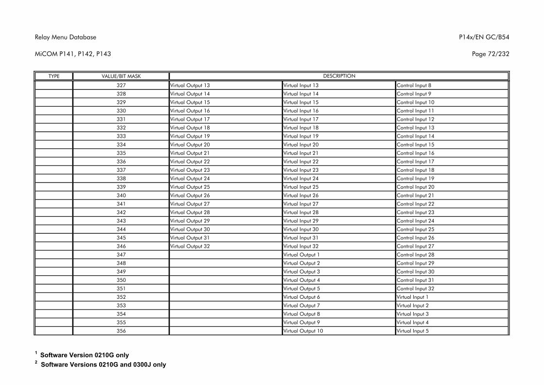
Relay Menu Database
MiCOM P141, P142, P143
P14x/EN GC/B54
Page 72/232
TYPE VALUE/BIT MASK DESCRIPTION
327 Virtual Output 13 Virtual Input 13 Control Input 8
328 Virtual Output 14 Virtual Input 14 Control Input 9
329 Virtual Output 15 Virtual Input 15 Control Input 10
330 Virtual Output 16 Virtual Input 16 Control Input 11
331 Virtual Output 17 Virtual Input 17 Control Input 12
332 Virtual Output 18 Virtual Input 18 Control Input 13
333 Virtual Output 19 Virtual Input 19 Control Input 14
334 Virtual Output 20 Virtual Input 20 Control Input 15
335 Virtual Output 21 Virtual Input 21 Control Input 16
336 Virtual Output 22 Virtual Input 22 Control Input 17
337 Virtual Output 23 Virtual Input 23 Control Input 18
338 Virtual Output 24 Virtual Input 24 Control Input 19
339 Virtual Output 25 Virtual Input 25 Control Input 20
340 Virtual Output 26 Virtual Input 26 Control Input 21
341 Virtual Output 27 Virtual Input 27 Control Input 22
342 Virtual Output 28 Virtual Input 28 Control Input 23
343 Virtual Output 29 Virtual Input 29 Control Input 24
344 Virtual Output 30 Virtual Input 30 Control Input 25
345 Virtual Output 31 Virtual Input 31 Control Input 26
346 Virtual Output 32 Virtual Input 32 Control Input 27
347 Virtual Output 1 Control Input 28
348 Virtual Output 2 Control Input 29
349 Virtual Output 3 Control Input 30
350 Virtual Output 4 Control Input 31
351 Virtual Output 5 Control Input 32
352 Virtual Output 6 Virtual Input 1
353 Virtual Output 7 Virtual Input 2
354 Virtual Output 8 Virtual Input 3
355 Virtual Output 9 Virtual Input 4
356 Virtual Output 10 Virtual Input 5
1 Software Version 0210G only2 Software Versions 0210G and 0300J only
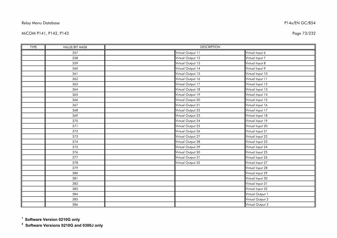
Relay Menu Database
MiCOM P141, P142, P143
P14x/EN GC/B54
Page 73/232
TYPE VALUE/BIT MASK DESCRIPTION
357 Virtual Output 11 Virtual Input 6
358 Virtual Output 12 Virtual Input 7
359 Virtual Output 13 Virtual Input 8
360 Virtual Output 14 Virtual Input 9
361 Virtual Output 15 Virtual Input 10
362 Virtual Output 16 Virtual Input 11
363 Virtual Output 17 Virtual Input 12
364 Virtual Output 18 Virtual Input 13
365 Virtual Output 19 Virtual Input 14
366 Virtual Output 20 Virtual Input 15
367 Virtual Output 21 Virtual Input 16
368 Virtual Output 22 Virtual Input 17
369 Virtual Output 23 Virtual Input 18
370 Virtual Output 24 Virtual Input 19
371 Virtual Output 25 Virtual Input 20
372 Virtual Output 26 Virtual Input 21
373 Virtual Output 27 Virtual Input 22
374 Virtual Output 28 Virtual Input 23
375 Virtual Output 29 Virtual Input 24
376 Virtual Output 30 Virtual Input 25
377 Virtual Output 31 Virtual Input 26
378 Virtual Output 32 Virtual Input 27
379 Virtual Input 28
380 Virtual Input 29
381 Virtual Input 30
382 Virtual Input 31
383 Virtual Input 32
384 Virtual Output 1
385 Virtual Output 2
386 Virtual Output 3
1 Software Version 0210G only2 Software Versions 0210G and 0300J only
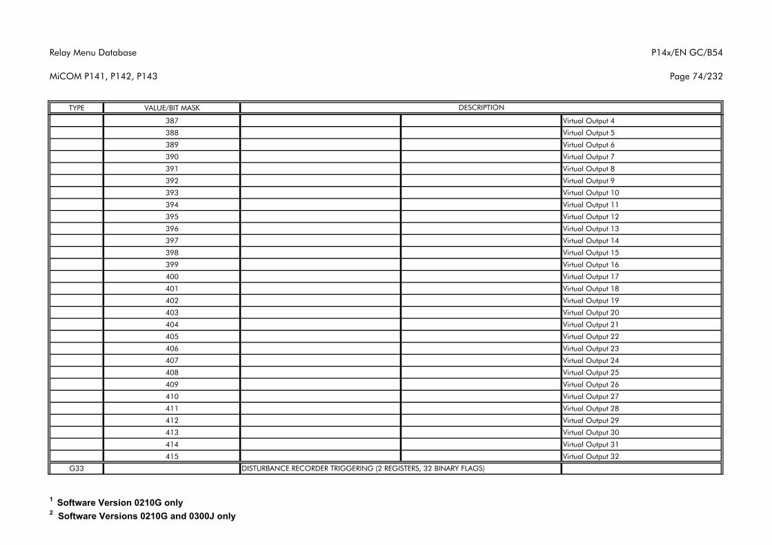
Relay Menu Database
MiCOM P141, P142, P143
P14x/EN GC/B54
Page 74/232
TYPE VALUE/BIT MASK DESCRIPTION
387 Virtual Output 4
388 Virtual Output 5
389 Virtual Output 6
390 Virtual Output 7
391 Virtual Output 8
392 Virtual Output 9
393 Virtual Output 10
394 Virtual Output 11
395 Virtual Output 12
396 Virtual Output 13
397 Virtual Output 14
398 Virtual Output 15
399 Virtual Output 16
400 Virtual Output 17
401 Virtual Output 18
402 Virtual Output 19
403 Virtual Output 20
404 Virtual Output 21
405 Virtual Output 22
406 Virtual Output 23
407 Virtual Output 24
408 Virtual Output 25
409 Virtual Output 26
410 Virtual Output 27
411 Virtual Output 28
412 Virtual Output 29
413 Virtual Output 30
414 Virtual Output 31
415 Virtual Output 32
G33 DISTURBANCE RECORDER TRIGGERING (2 REGISTERS, 32 BINARY FLAGS)
1 Software Version 0210G only2 Software Versions 0210G and 0300J only
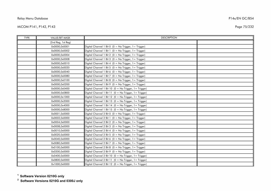
Relay Menu Database
MiCOM P141, P142, P143
P14x/EN GC/B54
Page 75/232
TYPE VALUE/BIT MASK DESCRIPTION
(2nd Reg, 1st Reg)
0x0000,0x0001 Digital Channel 1 Bit 0 (0 = No Trigger, 1= Trigger)
0x0000,0x0002 Digital Channel 1 Bit 1 (0 = No Trigger, 1= Trigger)
0x0000,0x0004 Digital Channel 1 Bit 2 (0 = No Trigger, 1= Trigger)
0x0000,0x0008 Digital Channel 1 Bit 3 (0 = No Trigger, 1= Trigger)
0x0000,0x0010 Digital Channel 1 Bit 4 (0 = No Trigger, 1= Trigger)
0x0000,0x0020 Digital Channel 1 Bit 5 (0 = No Trigger, 1= Trigger)
0x0000,0x0040 Digital Channel 1 Bit 6 (0 = No Trigger, 1= Trigger)
0x0000,0x0080 Digital Channel 1 Bit 7 (0 = No Trigger, 1= Trigger)
0x0000,0x0100 Digital Channel 1 Bit 8 (0 = No Trigger, 1= Trigger)
0x0000,0x0200 Digital Channel 1 Bit 9 (0 = No Trigger, 1= Trigger)
0x0000,0x0400 Digital Channel 1 Bit 10 (0 = No Trigger, 1= Trigger)
0x0000,0x0800 Digital Channel 1 Bit 11 (0 = No Trigger, 1= Trigger)
0x0000,0x1000 Digital Channel 1 Bit 12 (0 = No Trigger, 1= Trigger)
0x0000,0x2000 Digital Channel 1 Bit 13 (0 = No Trigger, 1= Trigger)
0x0000,0x4000 Digital Channel 1 Bit 14 (0 = No Trigger, 1= Trigger)
0x0000,0x8000 Digital Channel 1 Bit 15 (0 = No Trigger, 1= Trigger)
0x0001,0x0000 Digital Channel 2 Bit 0 (0 = No Trigger, 1= Trigger)
0x0002,0x0000 Digital Channel 2 Bit 1 (0 = No Trigger, 1= Trigger)
0x0004,0x0000 Digital Channel 2 Bit 2 (0 = No Trigger, 1= Trigger)
0x0008,0x0000 Digital Channel 2 Bit 3 (0 = No Trigger, 1= Trigger)
0x0010,0x0000 Digital Channel 2 Bit 4 (0 = No Trigger, 1= Trigger)
0x0020,0x0000 Digital Channel 2 Bit 5 (0 = No Trigger, 1= Trigger)
0x0040,0x0000 Digital Channel 2 Bit 6 (0 = No Trigger, 1= Trigger)
0x0080,0x0000 Digital Channel 2 Bit 7 (0 = No Trigger, 1= Trigger)
0x0100,0x0000 Digital Channel 2 Bit 8 (0 = No Trigger, 1= Trigger)
0x0200,0x0000 Digital Channel 2 Bit 9 (0 = No Trigger, 1= Trigger)
0x0400,0x0000 Digital Channel 2 Bit 10 (0 = No Trigger, 1= Trigger)
0x0800,0x0000 Digital Channel 2 Bit 11 (0 = No Trigger, 1= Trigger)
0x1000,0x0000 Digital Channel 2 Bit 12 (0 = No Trigger, 1= Trigger)
1 Software Version 0210G only2 Software Versions 0210G and 0300J only
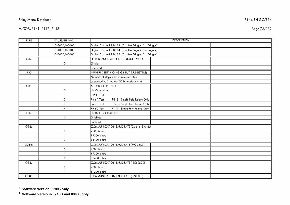
Relay Menu Database
MiCOM P141, P142, P143
P14x/EN GC/B54
Page 76/232
TYPE VALUE/BIT MASK DESCRIPTION
0x2000,0x0000 Digital Channel 2 Bit 13 (0 = No Trigger, 1= Trigger)
0x4000,0x0000 Digital Channel 2 Bit 14 (0 = No Trigger, 1= Trigger)
0x8000,0x0000 Digital Channel 2 Bit 15 (0 = No Trigger, 1= Trigger)
G34 DISTURBANCE RECORDER TRIGGER MODE
0 Single
1 Extended
G35 NUMERIC SETTING (AS G2 BUT 2 REGISTERS)
Number of steps from minimum value
expressed as 2 register 32 bit unsigned int
G36 AUTORECLOSE TEST
0 No Operation
1 3 Pole Test
2 Pole A Test P143 - Single Pole Relays Only
3 Pole B Test P143 - Single Pole Relays Only
4 Pole C Test P143 - Single Pole Relays Only
G37 ENABLED / DISABLED
0 Disabled
1 Enabled
G38c COMMUNICATION BAUD RATE (Courier-EIA485)
0
1
2
G38m COMMUNICATION BAUD RATE (MODBUS)
0 9600 bits/s
1 19200 bits/s
2 38400 bits/s
G38v COMMUNICATION BAUD RATE (IEC60870)
0 9600 bits/s
1 19200 bits/s
G38d COMMUNICATION BAUD RATE (DNP 3.0)
38400 bits/s
9600 bits/s
19200 bits/s
1 Software Version 0210G only2 Software Versions 0210G and 0300J only
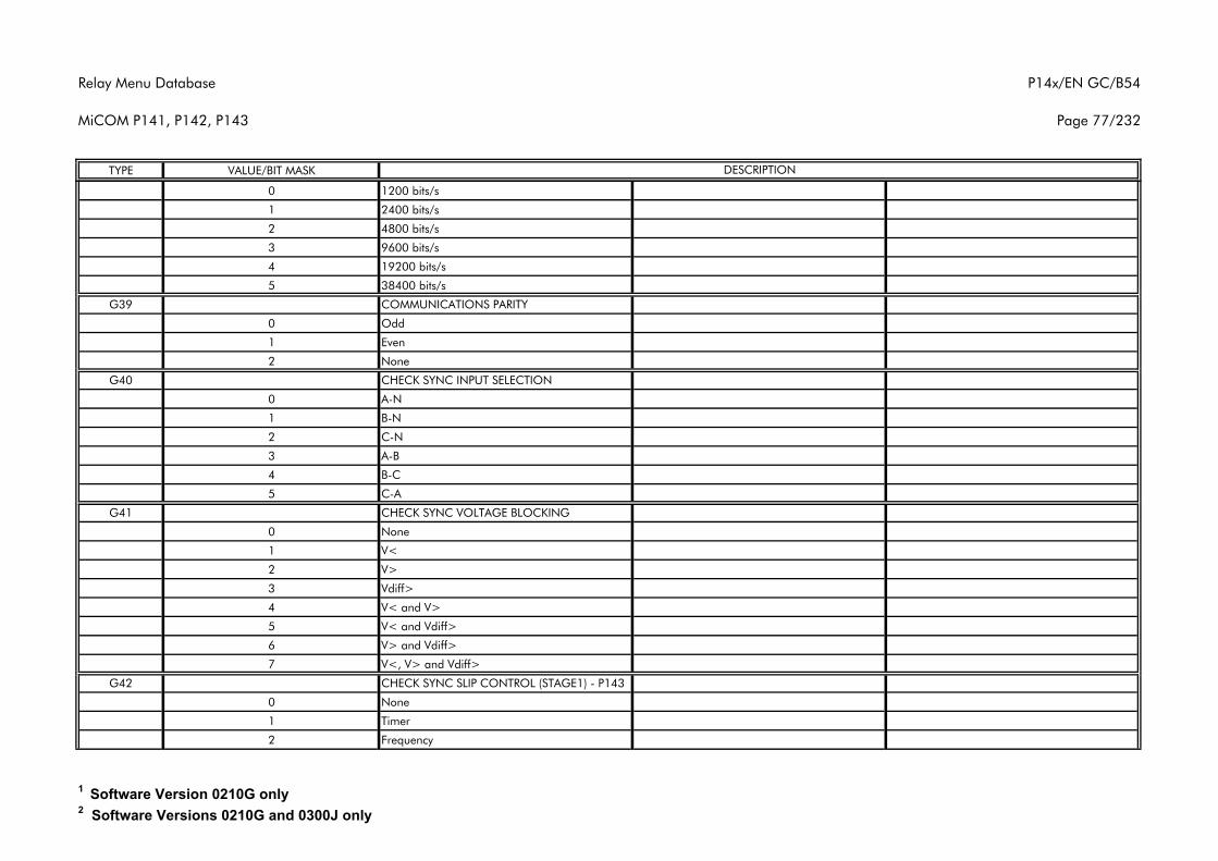
Relay Menu Database
MiCOM P141, P142, P143
P14x/EN GC/B54
Page 77/232
TYPE VALUE/BIT MASK DESCRIPTION
0 1200 bits/s
1 2400 bits/s
2 4800 bits/s
3 9600 bits/s
4 19200 bits/s
5 38400 bits/s
G39 COMMUNICATIONS PARITY
0 Odd
1 Even
2 None
G40 CHECK SYNC INPUT SELECTION
0 A-N
1 B-N
2 C-N
3 A-B
4 B-C
5 C-A
G41 CHECK SYNC VOLTAGE BLOCKING
0 None
1 V<
2 V>
3 Vdiff>
4 V< and V>
5 V< and Vdiff>
6 V> and Vdiff>
7 V<, V> and Vdiff>
G42 CHECK SYNC SLIP CONTROL (STAGE1) - P143
0 None
1 Timer
2 Frequency
1 Software Version 0210G only2 Software Versions 0210G and 0300J only
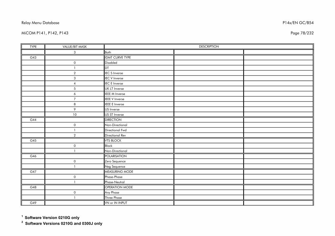
Relay Menu Database
MiCOM P141, P142, P143
P14x/EN GC/B54
Page 78/232
TYPE VALUE/BIT MASK DESCRIPTION
3 Both
G43 IDMT CURVE TYPE
0 Disabled
1 DT
2 IEC S Inverse
3 IEC V Inverse
4 IEC E Inverse
5 UK LT Inverse
6 IEEE M Inverse
7 IEEE V Inverse
8 IEEE E Inverse
9 US Inverse
10 US ST Inverse
G44 DIRECTION
0 Non-Directional
1 Directional Fwd
2 Directional Rev
G45 VTS BLOCK
0 Block
1 Non-Directional
G46 POLARISATION
0 Zero Sequence
1 Neg Sequence
G47 MEASURING MODE
0 Phase-Phase
1 Phase-Neutral
G48 OPERATION MODE
0 Any Phase
1 Three Phase
G49 VN or IN INPUT
1 Software Version 0210G only2 Software Versions 0210G and 0300J only
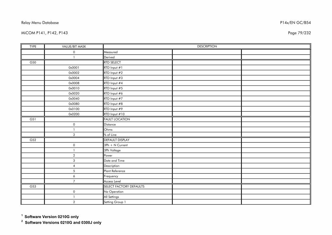
Relay Menu Database
MiCOM P141, P142, P143
P14x/EN GC/B54
Page 79/232
TYPE VALUE/BIT MASK DESCRIPTION
0 Measured
1 Derived
G50 RTD SELECT
0x0001 RTD Input #1
0x0002 RTD Input #2
0x0004 RTD Input #3
0x0008 RTD Input #4
0x0010 RTD Input #5
0x0020 RTD Input #6
0x0040 RTD Input #7
0x0080 RTD Input #8
0x0100 RTD Input #9
0x0200 RTD Input #10
G51 FAULT LOCATION
0 Distance
1 Ohms
2 % of Line
G52 DEFAULT DISPLAY
0 3Ph + N Current
1 3Ph Voltage
2 Power
3 Date and Time
4 Description
5 Plant Reference
6 Frequency
7 Access Level
G53 SELECT FACTORY DEFAULTS
0 No Operation
1 All Settings
2 Setting Group 1
1 Software Version 0210G only2 Software Versions 0210G and 0300J only
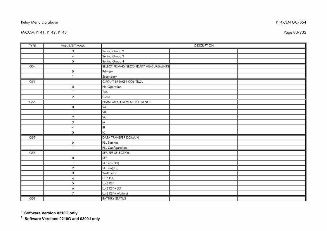
Relay Menu Database
MiCOM P141, P142, P143
P14x/EN GC/B54
Page 80/232
TYPE VALUE/BIT MASK DESCRIPTION
3 Setting Group 2
4 Setting Group 3
5 Setting Group 4
G54 SELECT PRIMARY SECONDARY MEASUREMENTS
0 Primary
1 Secondary
G55 CIRCUIT BREAKER CONTROL
0 No Operation
1 Trip
2 Close
G56 PHASE MEASUREMENT REFERENCE
0 VA
1 VB
2 VC
3 IA
4 IB
5 IC
G57 DATA TRANSFER DOMAIN
0 PSL Settings
1 PSL Configuration
G58 SEF/REF SELECTION
0 SEF
1 SEF cos(PHI)
2 SEF sin(PHI)
3 Wattmetric
4 Hi Z REF
5 Lo Z REF
6 Lo Z REF+SEF
7 Lo Z REF+Wattmet
G59 BATTERY STATUS
1 Software Version 0210G only2 Software Versions 0210G and 0300J only
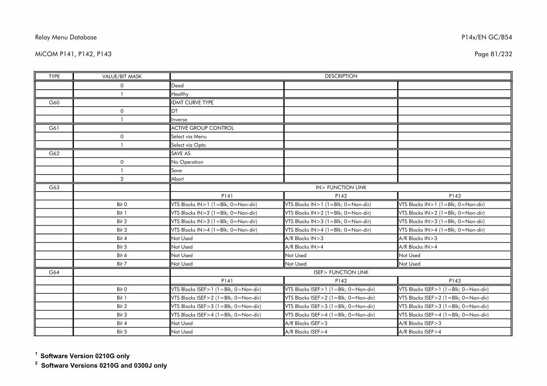
Relay Menu Database
MiCOM P141, P142, P143
P14x/EN GC/B54
Page 81/232
TYPE VALUE/BIT MASK DESCRIPTION
0 Dead
1 Healthy
G60 IDMT CURVE TYPE
0 DT
1 Inverse
G61 ACTIVE GROUP CONTROL
0 Select via Menu
1 Select via Opto
G62 SAVE AS
0 No Operation
1 Save
2 Abort
G63
P141 P142 P143
Bit 0 VTS Blocks IN>1 (1=Blk; 0=Non-dir) VTS Blocks IN>1 (1=Blk; 0=Non-dir) VTS Blocks IN>1 (1=Blk; 0=Non-dir)
Bit 1 VTS Blocks IN>2 (1=Blk; 0=Non-dir) VTS Blocks IN>2 (1=Blk; 0=Non-dir) VTS Blocks IN>2 (1=Blk; 0=Non-dir)
Bit 2 VTS Blocks IN>3 (1=Blk; 0=Non-dir) VTS Blocks IN>3 (1=Blk; 0=Non-dir) VTS Blocks IN>3 (1=Blk; 0=Non-dir)
Bit 3 VTS Blocks IN>4 (1=Blk; 0=Non-dir) VTS Blocks IN>4 (1=Blk; 0=Non-dir) VTS Blocks IN>4 (1=Blk; 0=Non-dir)
Bit 4 Not Used A/R Blocks IN>3 A/R Blocks IN>3
Bit 5 Not Used A/R Blocks IN>4 A/R Blocks IN>4
Bit 6 Not Used Not Used Not Used
Bit 7 Not Used Not Used Not Used
G64
P141 P142 P143
Bit 0 VTS Blocks ISEF>1 (1=Blk; 0=Non-dir) VTS Blocks ISEF>1 (1=Blk; 0=Non-dir) VTS Blocks ISEF>1 (1=Blk; 0=Non-dir)
Bit 1 VTS Blocks ISEF>2 (1=Blk; 0=Non-dir) VTS Blocks ISEF>2 (1=Blk; 0=Non-dir) VTS Blocks ISEF>2 (1=Blk; 0=Non-dir)
Bit 2 VTS Blocks ISEF>3 (1=Blk; 0=Non-dir) VTS Blocks ISEF>3 (1=Blk; 0=Non-dir) VTS Blocks ISEF>3 (1=Blk; 0=Non-dir)
Bit 3 VTS Blocks ISEF>4 (1=Blk; 0=Non-dir) VTS Blocks ISEF>4 (1=Blk; 0=Non-dir) VTS Blocks ISEF>4 (1=Blk; 0=Non-dir)
Bit 4 Not Used A/R Blocks ISEF>3 A/R Blocks ISEF>3
Bit 5 Not Used A/R Blocks ISEF>4 A/R Blocks ISEF>4
IN> FUNCTION LINK
ISEF> FUNCTION LINK
1 Software Version 0210G only2 Software Versions 0210G and 0300J only
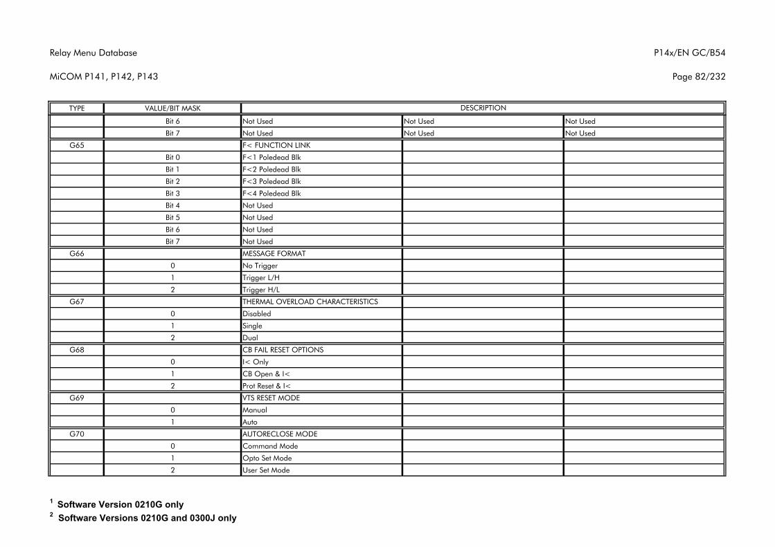
Relay Menu Database
MiCOM P141, P142, P143
P14x/EN GC/B54
Page 82/232
TYPE VALUE/BIT MASK DESCRIPTION
Bit 6 Not Used Not Used Not Used
Bit 7 Not Used Not Used Not Used
G65 F< FUNCTION LINK
Bit 0 F<1 Poledead Blk
Bit 1 F<2 Poledead Blk
Bit 2 F<3 Poledead Blk
Bit 3 F<4 Poledead Blk
Bit 4 Not Used
Bit 5 Not Used
Bit 6 Not Used
Bit 7 Not Used
G66 MESSAGE FORMAT
0 No Trigger
1 Trigger L/H
2 Trigger H/L
G67 THERMAL OVERLOAD CHARACTERISTICS
0 Disabled
1 Single
2 Dual
G68 CB FAIL RESET OPTIONS
0 I< Only
1 CB Open & I<
2 Prot Reset & I<
G69 VTS RESET MODE
0 Manual
1 Auto
G70 AUTORECLOSE MODE
0 Command Mode
1 Opto Set Mode
2 User Set Mode
1 Software Version 0210G only2 Software Versions 0210G and 0300J only
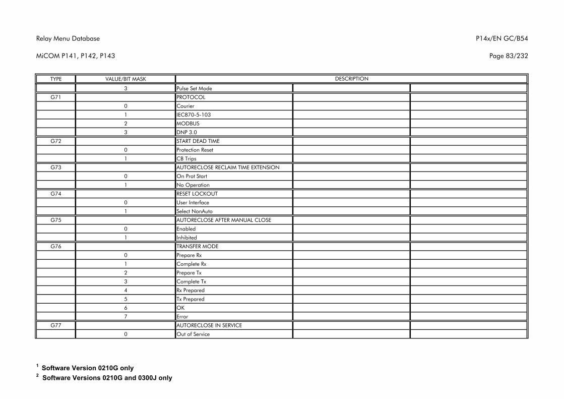
Relay Menu Database
MiCOM P141, P142, P143
P14x/EN GC/B54
Page 83/232
TYPE VALUE/BIT MASK DESCRIPTION
3 Pulse Set Mode
G71 PROTOCOL
0 Courier
1 IEC870-5-103
2 MODBUS
3 DNP 3.0
G72 START DEAD TIME
0 Protection Reset
1 CB Trips
G73 AUTORECLOSE RECLAIM TIME EXTENSION
0 On Prot Start
1 No Operation
G74 RESET LOCKOUT
0 User Interface
1 Select NonAuto
G75 AUTORECLOSE AFTER MANUAL CLOSE
0 Enabled
1 Inhibited
G76 TRANSFER MODE
0 Prepare Rx
1 Complete Rx
2 Prepare Tx
3 Complete Tx
4 Rx Prepared
5 Tx Prepared
6 OK
7 Error
G77 AUTORECLOSE IN SERVICE
0 Out of Service
1 Software Version 0210G only2 Software Versions 0210G and 0300J only
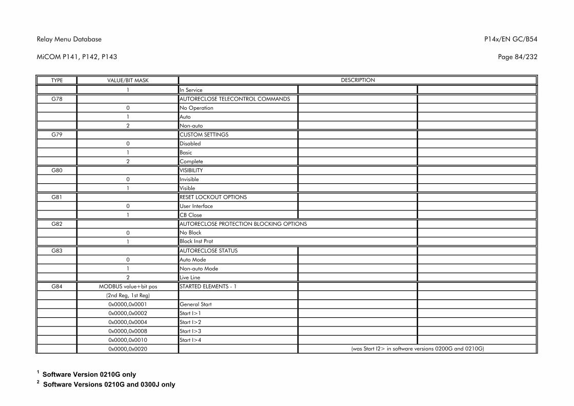
Relay Menu Database
MiCOM P141, P142, P143
P14x/EN GC/B54
Page 84/232
TYPE VALUE/BIT MASK DESCRIPTION
1 In Service
G78 AUTORECLOSE TELECONTROL COMMANDS
0 No Operation
1 Auto
2 Non-auto
G79 CUSTOM SETTINGS
0 Disabled
1 Basic
2 Complete
G80 VISIBILITY
0 Invisible
1 Visible
G81 RESET LOCKOUT OPTIONS
0 User Interface
1 CB Close
G82 AUTORECLOSE PROTECTION BLOCKING OPTIONS
0
1
G83 AUTORECLOSE STATUS
0 Auto Mode
1 Non-auto Mode
2 Live Line
G84 MODBUS value+bit pos STARTED ELEMENTS - 1
(2nd Reg, 1st Reg)
0x0000,0x0001 General Start
0x0000,0x0002 Start I>1
0x0000,0x0004 Start I>2
0x0000,0x0008 Start I>3
0x0000,0x0010 Start I>4
0x0000,0x0020
No Block
Block Inst Prot
(was Start I2> in software versions 0200G and 0210G)
1 Software Version 0210G only2 Software Versions 0210G and 0300J only
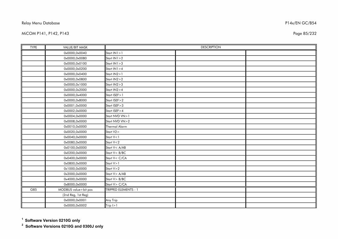
Relay Menu Database
MiCOM P141, P142, P143
P14x/EN GC/B54
Page 85/232
TYPE VALUE/BIT MASK DESCRIPTION
0x0000,0x0040 Start IN1>1
0x0000,0x0080 Start IN1>2
0x0000,0x0100 Start IN1>3
0x0000,0x0200 Start IN1>4
0x0000,0x0400 Start IN2>1
0x0000,0x0800 Start IN2>2
0x0000,0x1000 Start IN2>3
0x0000,0x2000 Start IN2>4
0x0000,0x4000 Start ISEF>1
0x0000,0x8000 Start ISEF>2
0x0001,0x0000 Start ISEF>3
0x0002,0x0000 Start ISEF>4
0x0004,0x0000 Start NVD VN>1
0x0008,0x0000 Start NVD VN>2
0x0010,0x0000 Thermal Alarm
0x0020,0x0000 Start V2>
0x0040,0x0000 Start V<1
0x0080,0x0000 Start V<2
0x0100,0x0000 Start V< A/AB
0x0200,0x0000 Start V< B/BC
0x0400,0x0000 Start V< C/CA
0x0800,0x0000 Start V>1
0x1000,0x0000 Start V>2
0x2000,0x0000 Start V> A/AB
0x4000,0x0000 Start V> B/BC
0x8000,0x0000 Start V> C/CA
G85 MODBUS value+bit pos TRIPPED ELEMENTS - 1
(2nd Reg, 1st Reg)
0x0000,0x0001 Any Trip
0x0000,0x0002 Trip I>1
1 Software Version 0210G only2 Software Versions 0210G and 0300J only
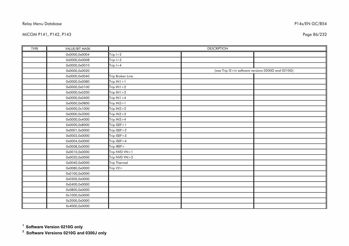
Relay Menu Database
MiCOM P141, P142, P143
P14x/EN GC/B54
Page 86/232
TYPE VALUE/BIT MASK DESCRIPTION
0x0000,0x0004 Trip I>2
0x0000,0x0008 Trip I>3
0x0000,0x0010 Trip I>4
0x0000,0x0020
0x0000,0x0040 Trip Broken Line
0x0000,0x0080 Trip IN1>1
0x0000,0x0100 Trip IN1>2
0x0000,0x0200 Trip IN1>3
0x0000,0x0400 Trip IN1>4
0x0000,0x0800 Trip IN2>1
0x0000,0x1000 Trip IN2>2
0x0000,0x2000 Trip IN2>3
0x0000,0x4000 Trip IN2>4
0x0000,0x8000 Trip ISEF>1
0x0001,0x0000 Trip ISEF>2
0x0002,0x0000 Trip ISEF>3
0x0004,0x0000 Trip ISEF>4
0x0008,0x0000 Trip IREF>
0x0010,0x0000 Trip NVD VN>1
0x0020,0x0000 Trip NVD VN>2
0x0040,0x0000 Trip Thermal
0x0080,0x0000 Trip V2>
0x0100,0x0000
0x0200,0x0000
0x0400,0x0000
0x0800,0x0000
0x1000,0x0000
0x2000,0x0000
0x4000,0x0000
(was Trip I2>in software versions 0200G and 0210G)
1 Software Version 0210G only2 Software Versions 0210G and 0300J only
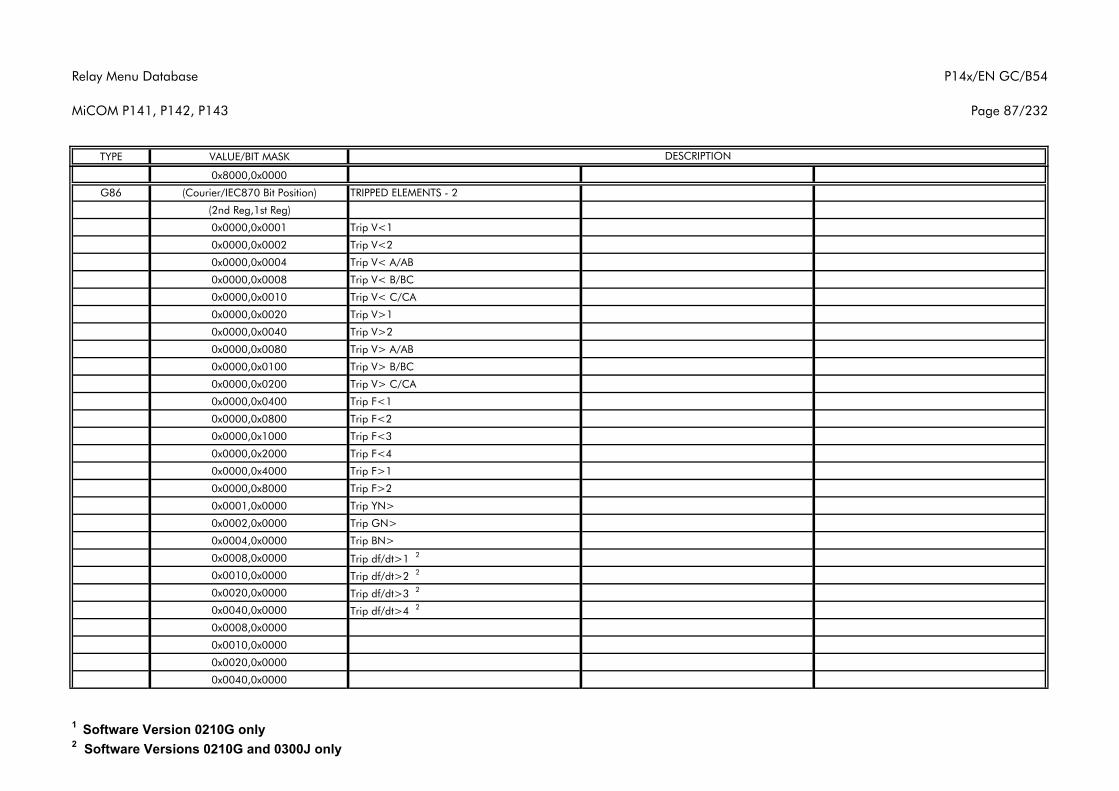
Relay Menu Database
MiCOM P141, P142, P143
P14x/EN GC/B54
Page 87/232
TYPE VALUE/BIT MASK DESCRIPTION
0x8000,0x0000
G86 (Courier/IEC870 Bit Position) TRIPPED ELEMENTS - 2
(2nd Reg,1st Reg)
0x0000,0x0001 Trip V<1
0x0000,0x0002 Trip V<2
0x0000,0x0004 Trip V< A/AB
0x0000,0x0008 Trip V< B/BC
0x0000,0x0010 Trip V< C/CA
0x0000,0x0020 Trip V>1
0x0000,0x0040 Trip V>2
0x0000,0x0080 Trip V> A/AB
0x0000,0x0100 Trip V> B/BC
0x0000,0x0200 Trip V> C/CA
0x0000,0x0400 Trip F<1
0x0000,0x0800 Trip F<2
0x0000,0x1000 Trip F<3
0x0000,0x2000 Trip F<4
0x0000,0x4000 Trip F>1
0x0000,0x8000 Trip F>2
0x0001,0x0000 Trip YN>
0x0002,0x0000 Trip GN>
0x0004,0x0000 Trip BN>
0x0008,0x0000 Trip df/dt>1 2
0x0010,0x0000 Trip df/dt>2 2
0x0020,0x0000 Trip df/dt>3 2
0x0040,0x0000 Trip df/dt>4 2
0x0008,0x0000
0x0010,0x0000
0x0020,0x0000
0x0040,0x0000
1 Software Version 0210G only2 Software Versions 0210G and 0300J only
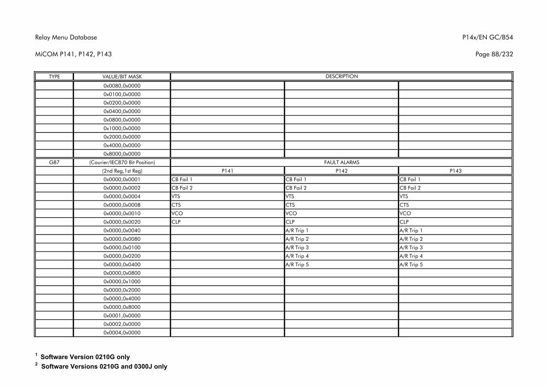
Relay Menu Database
MiCOM P141, P142, P143
P14x/EN GC/B54
Page 88/232
TYPE VALUE/BIT MASK DESCRIPTION
0x0080,0x0000
0x0100,0x0000
0x0200,0x0000
0x0400,0x0000
0x0800,0x0000
0x1000,0x0000
0x2000,0x0000
0x4000,0x0000
0x8000,0x0000
G87 (Courier/IEC870 Bit Position)
(2nd Reg,1st Reg) P141 P142 P143
0x0000,0x0001 CB Fail 1 CB Fail 1 CB Fail 1
0x0000,0x0002 CB Fail 2 CB Fail 2 CB Fail 2
0x0000,0x0004 VTS VTS VTS
0x0000,0x0008 CTS CTS CTS
0x0000,0x0010 VCO VCO VCO
0x0000,0x0020 CLP CLP CLP
0x0000,0x0040 A/R Trip 1 A/R Trip 1
0x0000,0x0080 A/R Trip 2 A/R Trip 2
0x0000,0x0100 A/R Trip 3 A/R Trip 3
0x0000,0x0200 A/R Trip 4 A/R Trip 4
0x0000,0x0400 A/R Trip 5 A/R Trip 5
0x0000,0x0800
0x0000,0x1000
0x0000,0x2000
0x0000,0x4000
0x0000,0x8000
0x0001,0x0000
0x0002,0x0000
0x0004,0x0000
FAULT ALARMS
1 Software Version 0210G only2 Software Versions 0210G and 0300J only
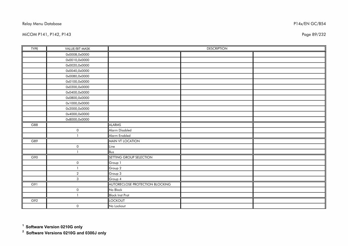
Relay Menu Database
MiCOM P141, P142, P143
P14x/EN GC/B54
Page 89/232
TYPE VALUE/BIT MASK DESCRIPTION
0x0008,0x0000
0x0010,0x0000
0x0020,0x0000
0x0040,0x0000
0x0080,0x0000
0x0100,0x0000
0x0200,0x0000
0x0400,0x0000
0x0800,0x0000
0x1000,0x0000
0x2000,0x0000
0x4000,0x0000
0x8000,0x0000
G88 ALARMS
0 Alarm Disabled
1 Alarm Enabled
G89 MAIN VT LOCATION
0 Line
1 Bus
G90 SETTING GROUP SELECTION
0 Group 1
1 Group 2
2 Group 3
3 Group 4
G91 AUTORECLOSE PROTECTION BLOCKING
0 No Block
1 Block Inst Prot
G92 LOCKOUT
0 No Lockout
1 Software Version 0210G only2 Software Versions 0210G and 0300J only
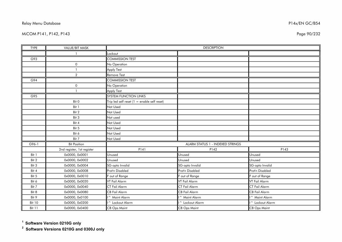
Relay Menu Database
MiCOM P141, P142, P143
P14x/EN GC/B54
Page 90/232
TYPE VALUE/BIT MASK DESCRIPTION
1 Lockout
G93 COMMISSION TEST
0 No Operation
1 Apply Test
2 Remove Test
G94 COMMISSION TEST
0 No Operation
1 Apply Test
G95 SYSTEM FUNCTION LINKS
Bit 0 Trip led self reset (1 = enable self reset)
Bit 1 Not Used
Bit 2 Not Used
Bit 3 Not used
Bit 4 Not Used
Bit 5 Not Used
Bit 6 Not Used
Bit 7 Not Used
G96-1 Bit Position
2nd register, 1st register P141 P142 P143
Bit 1 0x0000, 0x0001 Unused Unused Unused
Bit 2 0x0000, 0x0002 Unused Unused Unused
Bit 3 0x0000, 0x0004 SG-opto Invalid SG-opto Invalid SG-opto Invalid
Bit 4 0x0000, 0x0008 Prot'n Disabled Prot'n Disabled Prot'n Disabled
Bit 5 0x0000, 0x0010 F out of Range F out of Range F out of Range
Bit 6 0x0000, 0x0020 VT Fail Alarm VT Fail Alarm VT Fail Alarm
Bit 7 0x0000, 0x0040 CT Fail Alarm CT Fail Alarm CT Fail Alarm
Bit 8 0x0000, 0x0080 CB Fail Alarm CB Fail Alarm CB Fail Alarm
Bit 9 0x0000, 0x0100 I^ Maint Alarm I^ Maint Alarm I^ Maint Alarm
Bit 10 0x0000, 0x0200 I^ Lockout Alarm I^ Lockout Alarm I^ Lockout Alarm
Bit 11 0x0000, 0x0400 CB Ops Maint CB Ops Maint CB Ops Maint
ALARM STATUS 1 - INDEXED STRINGS
1 Software Version 0210G only2 Software Versions 0210G and 0300J only
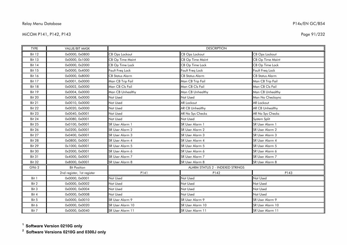
Relay Menu Database
MiCOM P141, P142, P143
P14x/EN GC/B54
Page 91/232
TYPE VALUE/BIT MASK DESCRIPTION
Bit 12 0x0000, 0x0800 CB Ops Lockout CB Ops Lockout CB Ops Lockout
Bit 13 0x0000, 0x1000 CB Op Time Maint CB Op Time Maint CB Op Time Maint
Bit 14 0x0000, 0x2000 CB Op Time Lock CB Op Time Lock CB Op Time Lock
Bit 15 0x0000, 0x4000 Fault Freq Lock Fault Freq Lock Fault Freq Lock
Bit 16 0x0000, 0x8000 CB Status Alarm CB Status Alarm CB Status Alarm
Bit 17 0x0001, 0x0000 Man CB Trip Fail Man CB Trip Fail Man CB Trip Fail
Bit 18 0x0002, 0x0000 Man CB Cls Fail Man CB Cls Fail Man CB Cls Fail
Bit 19 0x0004, 0x0000 Man CB Unhealthy Man CB Unhealthy Man CB Unhealthy
Bit 20 0x0008, 0x0000 Not Used Not Used Man No Checksync
Bit 21 0x0010, 0x0000 Not Used AR Lockout AR Lockout
Bit 22 0x0020, 0x0000 Not Used AR CB Unhealthy AR CB Unhealthy
Bit 23 0x0040, 0x0001 Not Used AR No Sys Checks AR No Sys Checks
Bit 24 0x0080, 0x0001 Not Used Not Used System Split
Bit 25 0x0100, 0x0001 SR User Alarm 1 SR User Alarm 1 SR User Alarm 1
Bit 26 0x0200, 0x0001 SR User Alarm 2 SR User Alarm 2 SR User Alarm 2
Bit 27 0x0400, 0x0001 SR User Alarm 3 SR User Alarm 3 SR User Alarm 3
Bit 28 0x0800, 0x0001 SR User Alarm 4 SR User Alarm 4 SR User Alarm 4
Bit 29 0x1000, 0x0001 SR User Alarm 5 SR User Alarm 5 SR User Alarm 5
Bit 30 0x2000, 0x0001 SR User Alarm 6 SR User Alarm 6 SR User Alarm 6
Bit 31 0x4000, 0x0001 SR User Alarm 7 SR User Alarm 7 SR User Alarm 7
Bit 32 0x8000, 0x0001 SR User Alarm 8 SR User Alarm 8 SR User Alarm 8
G96-2 Bit Position
2nd register, 1st register P141 P142 P143
Bit 1 0x0000, 0x0001 Not Used Not Used Not Used
Bit 2 0x0000, 0x0002 Not Used Not Used Not Used
Bit 3 0x0000, 0x0004 Not Used Not Used Not Used
Bit 4 0x0000, 0x0008 Not Used Not Used Not Used
Bit 5 0x0000, 0x0010 SR User Alarm 9 SR User Alarm 9 SR User Alarm 9
Bit 6 0x0000, 0x0020 SR User Alarm 10 SR User Alarm 10 SR User Alarm 10
Bit 7 0x0000, 0x0040 SR User Alarm 11 SR User Alarm 11 SR User Alarm 11
ALARM STATUS 2 - INDEXED STRINGS
1 Software Version 0210G only2 Software Versions 0210G and 0300J only
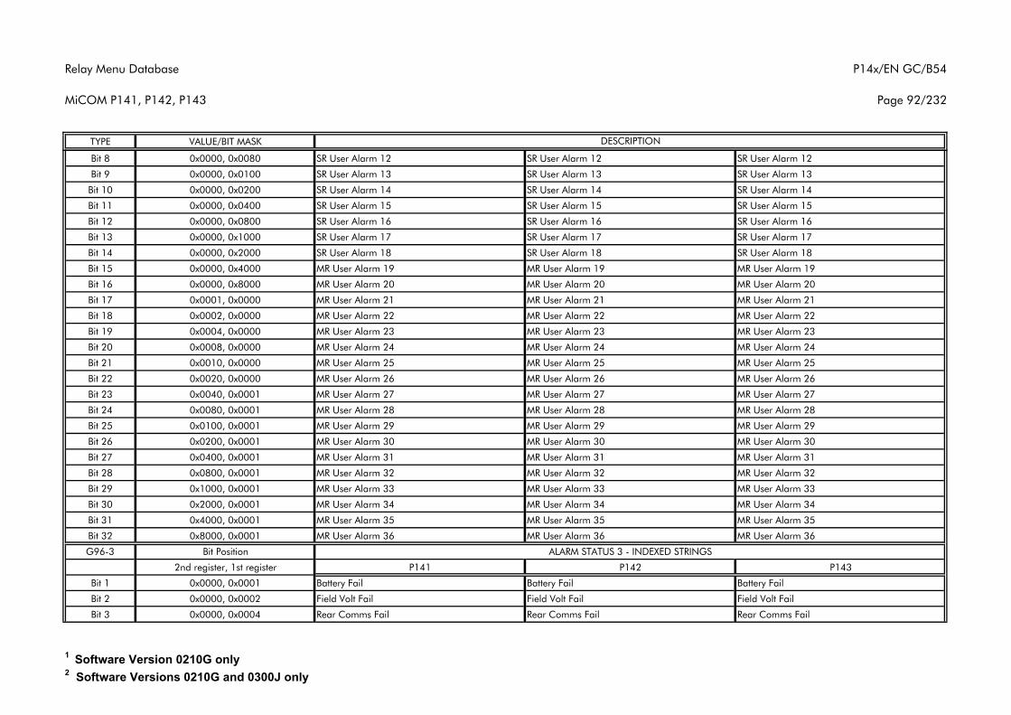
Relay Menu Database
MiCOM P141, P142, P143
P14x/EN GC/B54
Page 92/232
TYPE VALUE/BIT MASK DESCRIPTION
Bit 8 0x0000, 0x0080 SR User Alarm 12 SR User Alarm 12 SR User Alarm 12
Bit 9 0x0000, 0x0100 SR User Alarm 13 SR User Alarm 13 SR User Alarm 13
Bit 10 0x0000, 0x0200 SR User Alarm 14 SR User Alarm 14 SR User Alarm 14
Bit 11 0x0000, 0x0400 SR User Alarm 15 SR User Alarm 15 SR User Alarm 15
Bit 12 0x0000, 0x0800 SR User Alarm 16 SR User Alarm 16 SR User Alarm 16
Bit 13 0x0000, 0x1000 SR User Alarm 17 SR User Alarm 17 SR User Alarm 17
Bit 14 0x0000, 0x2000 SR User Alarm 18 SR User Alarm 18 SR User Alarm 18
Bit 15 0x0000, 0x4000 MR User Alarm 19 MR User Alarm 19 MR User Alarm 19
Bit 16 0x0000, 0x8000 MR User Alarm 20 MR User Alarm 20 MR User Alarm 20
Bit 17 0x0001, 0x0000 MR User Alarm 21 MR User Alarm 21 MR User Alarm 21
Bit 18 0x0002, 0x0000 MR User Alarm 22 MR User Alarm 22 MR User Alarm 22
Bit 19 0x0004, 0x0000 MR User Alarm 23 MR User Alarm 23 MR User Alarm 23
Bit 20 0x0008, 0x0000 MR User Alarm 24 MR User Alarm 24 MR User Alarm 24
Bit 21 0x0010, 0x0000 MR User Alarm 25 MR User Alarm 25 MR User Alarm 25
Bit 22 0x0020, 0x0000 MR User Alarm 26 MR User Alarm 26 MR User Alarm 26
Bit 23 0x0040, 0x0001 MR User Alarm 27 MR User Alarm 27 MR User Alarm 27
Bit 24 0x0080, 0x0001 MR User Alarm 28 MR User Alarm 28 MR User Alarm 28
Bit 25 0x0100, 0x0001 MR User Alarm 29 MR User Alarm 29 MR User Alarm 29
Bit 26 0x0200, 0x0001 MR User Alarm 30 MR User Alarm 30 MR User Alarm 30
Bit 27 0x0400, 0x0001 MR User Alarm 31 MR User Alarm 31 MR User Alarm 31
Bit 28 0x0800, 0x0001 MR User Alarm 32 MR User Alarm 32 MR User Alarm 32
Bit 29 0x1000, 0x0001 MR User Alarm 33 MR User Alarm 33 MR User Alarm 33
Bit 30 0x2000, 0x0001 MR User Alarm 34 MR User Alarm 34 MR User Alarm 34
Bit 31 0x4000, 0x0001 MR User Alarm 35 MR User Alarm 35 MR User Alarm 35
Bit 32 0x8000, 0x0001 MR User Alarm 36 MR User Alarm 36 MR User Alarm 36
G96-3 Bit Position
2nd register, 1st register P141 P142 P143
Bit 1 0x0000, 0x0001 Battery Fail Battery Fail Battery Fail
Bit 2 0x0000, 0x0002 Field Volt Fail Field Volt Fail Field Volt Fail
Bit 3 0x0000, 0x0004 Rear Comms Fail Rear Comms Fail Rear Comms Fail
ALARM STATUS 3 - INDEXED STRINGS
1 Software Version 0210G only2 Software Versions 0210G and 0300J only
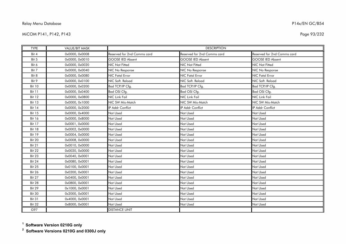
Relay Menu Database
MiCOM P141, P142, P143
P14x/EN GC/B54
Page 93/232
TYPE VALUE/BIT MASK DESCRIPTION
Bit 4 0x0000, 0x0008 Reserved for 2nd Comms card Reserved for 2nd Comms card Reserved for 2nd Comms card
Bit 5 0x0000, 0x0010 GOOSE IED Absent GOOSE IED Absent GOOSE IED Absent
Bit 6 0x0000, 0x0020 NIC Not Fitted NIC Not Fitted NIC Not Fitted
Bit 7 0x0000, 0x0040 NIC No Response NIC No Response NIC No Response
Bit 8 0x0000, 0x0080 NIC Fatal Error NIC Fatal Error NIC Fatal Error
Bit 9 0x0000, 0x0100 NIC Soft. Reload NIC Soft. Reload NIC Soft. Reload
Bit 10 0x0000, 0x0200 Bad TCP/IP Cfg. Bad TCP/IP Cfg. Bad TCP/IP Cfg.
Bit 11 0x0000, 0x0400 Bad OSI Cfg. Bad OSI Cfg. Bad OSI Cfg.
Bit 12 0x0000, 0x0800 NIC Link Fail NIC Link Fail NIC Link Fail
Bit 13 0x0000, 0x1000 NIC SW Mis-Match NIC SW Mis-Match NIC SW Mis-Match
Bit 14 0x0000, 0x2000 IP Addr Conflict IP Addr Conflict IP Addr Conflict
Bit 15 0x0000, 0x4000 Not Used Not Used Not Used
Bit 16 0x0000, 0x8000 Not Used Not Used Not Used
Bit 17 0x0001, 0x0000 Not Used Not Used Not Used
Bit 18 0x0002, 0x0000 Not Used Not Used Not Used
Bit 19 0x0004, 0x0000 Not Used Not Used Not Used
Bit 20 0x0008, 0x0000 Not Used Not Used Not Used
Bit 21 0x0010, 0x0000 Not Used Not Used Not Used
Bit 22 0x0020, 0x0000 Not Used Not Used Not Used
Bit 23 0x0040, 0x0001 Not Used Not Used Not Used
Bit 24 0x0080, 0x0001 Not Used Not Used Not Used
Bit 25 0x0100, 0x0001 Not Used Not Used Not Used
Bit 26 0x0200, 0x0001 Not Used Not Used Not Used
Bit 27 0x0400, 0x0001 Not Used Not Used Not Used
Bit 28 0x0800, 0x0001 Not Used Not Used Not Used
Bit 29 0x1000, 0x0001 Not Used Not Used Not Used
Bit 30 0x2000, 0x0001 Not Used Not Used Not Used
Bit 31 0x4000, 0x0001 Not Used Not Used Not Used
Bit 32 0x8000, 0x0001 Not Used Not Used Not Used
G97 DISTANCE UNIT
1 Software Version 0210G only2 Software Versions 0210G and 0300J only
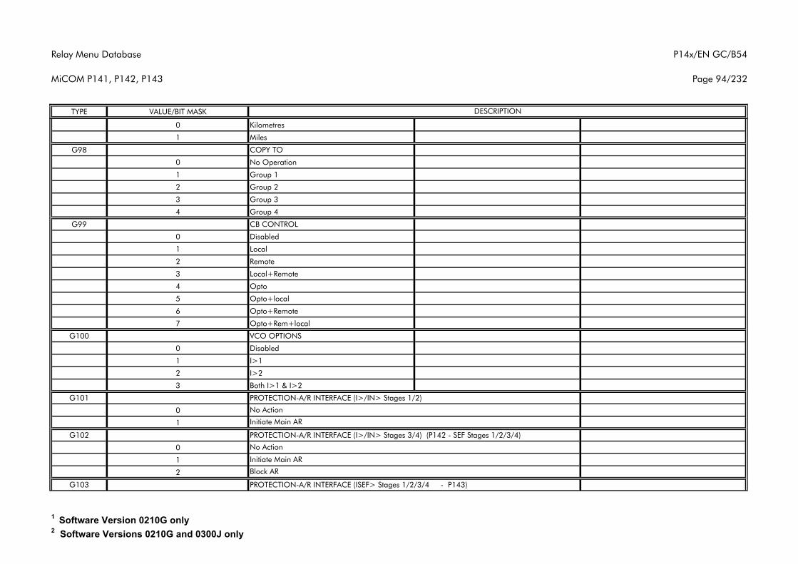
Relay Menu Database
MiCOM P141, P142, P143
P14x/EN GC/B54
Page 94/232
TYPE VALUE/BIT MASK DESCRIPTION
0 Kilometres
1 Miles
G98 COPY TO
0 No Operation
1 Group 1
2 Group 2
3 Group 3
4 Group 4
G99 CB CONTROL
0 Disabled
1 Local
2 Remote
3 Local+Remote
4 Opto
5 Opto+local
6 Opto+Remote
7 Opto+Rem+local
G100 VCO OPTIONS
0 Disabled
1 I>1
2 I>2
3 Both I>1 & I>2
G101 PROTECTION-A/R INTERFACE (I>/IN> Stages 1/2)
0
1
G102 PROTECTION-A/R INTERFACE (I>/IN> Stages 3/4) (P142 - SEF Stages 1/2/3/4)
0
1
2
G103 PROTECTION-A/R INTERFACE (ISEF> Stages 1/2/3/4 - P143)
No Action
No Action
Initiate Main AR
Initiate Main AR
Block AR
1 Software Version 0210G only2 Software Versions 0210G and 0300J only
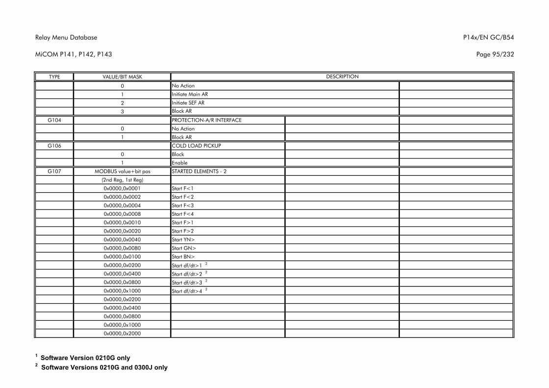
Relay Menu Database
MiCOM P141, P142, P143
P14x/EN GC/B54
Page 95/232
TYPE VALUE/BIT MASK DESCRIPTION
0
1
2
3
G104 PROTECTION-A/R INTERFACE
0 No Action
1 Block AR
G106 COLD LOAD PICKUP
0 Block
1 Enable
G107 MODBUS value+bit pos STARTED ELEMENTS - 2
(2nd Reg, 1st Reg)
0x0000,0x0001 Start F<1
0x0000,0x0002 Start F<2
0x0000,0x0004 Start F<3
0x0000,0x0008 Start F<4
0x0000,0x0010 Start F>1
0x0000,0x0020 Start F>2
0x0000,0x0040 Start YN>
0x0000,0x0080 Start GN>
0x0000,0x0100 Start BN>
0x0000,0x0200 Start df/dt>1 2
0x0000,0x0400 Start df/dt>2 2
0x0000,0x0800 Start df/dt>3 2
0x0000,0x1000 Start df/dt>4 2
0x0000,0x0200
0x0000,0x0400
0x0000,0x0800
0x0000,0x1000
0x0000,0x2000
Block AR
No Action
Initiate Main AR
Initiate SEF AR
1 Software Version 0210G only2 Software Versions 0210G and 0300J only
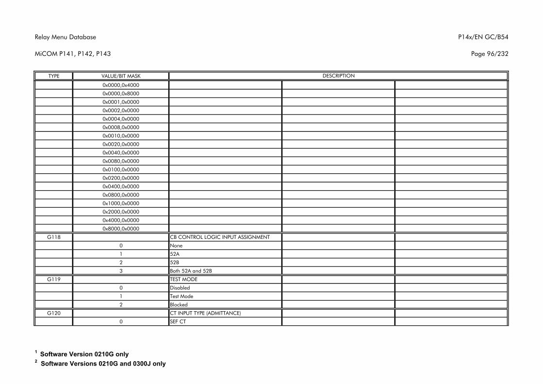
Relay Menu Database
MiCOM P141, P142, P143
P14x/EN GC/B54
Page 96/232
TYPE VALUE/BIT MASK DESCRIPTION
0x0000,0x4000
0x0000,0x8000
0x0001,0x0000
0x0002,0x0000
0x0004,0x0000
0x0008,0x0000
0x0010,0x0000
0x0020,0x0000
0x0040,0x0000
0x0080,0x0000
0x0100,0x0000
0x0200,0x0000
0x0400,0x0000
0x0800,0x0000
0x1000,0x0000
0x2000,0x0000
0x4000,0x0000
0x8000,0x0000
G118 CB CONTROL LOGIC INPUT ASSIGNMENT
0 None
1 52A
2 52B
3 Both 52A and 52B
G119 TEST MODE
0 Disabled
1 Test Mode
2 Blocked
G120 CT INPUT TYPE (ADMITTANCE)
0 SEF CT
1 Software Version 0210G only2 Software Versions 0210G and 0300J only
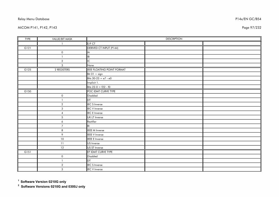
Relay Menu Database
MiCOM P141, P142, P143
P14x/EN GC/B54
Page 97/232
TYPE VALUE/BIT MASK DESCRIPTION
1 E/F CT
G121 DERIVED CT INPUT (P144)
0 IA
1 IB
2 IC
3 None
G125 2 REGISTERS IEEE FLOATING POINT FORMAT
Bit 31 = sign
Bits 30-23 = e7 - e0
Implicit 1.
Bits 22-0 = f22 - f0
G150 POC IDMT CURVE TYPE
0 Disabled
1 DT
2 IEC S Inverse
3 IEC V Inverse
4 IEC E Inverse
5 UK LT Inverse
6 Rectifier
7 RI
8 IEEE M Inverse
9 IEEE V Inverse
10 IEEE E Inverse
11 US Inverse
12 US ST Inverse
G151 EF IDMT CURVE TYPE
0 Disabled
1 DT
2 IEC S Inverse
3 IEC V Inverse
1 Software Version 0210G only2 Software Versions 0210G and 0300J only
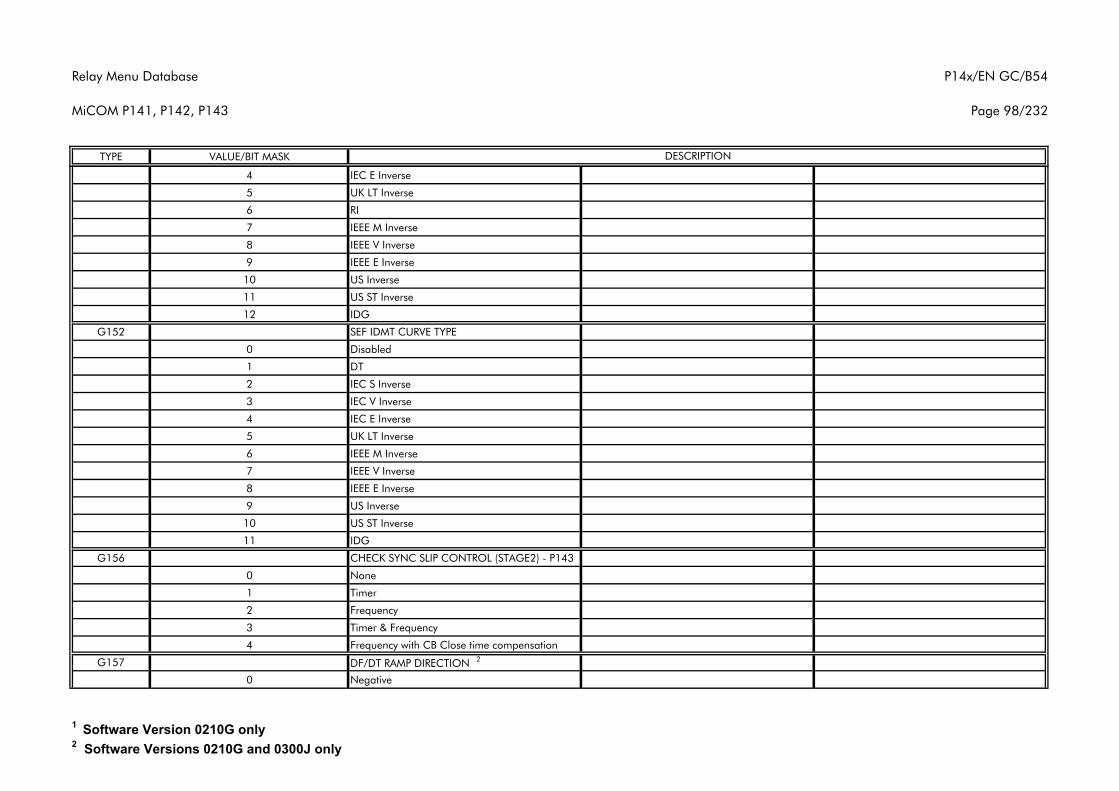
Relay Menu Database
MiCOM P141, P142, P143
P14x/EN GC/B54
Page 98/232
TYPE VALUE/BIT MASK DESCRIPTION
4 IEC E Inverse
5 UK LT Inverse
6 RI
7 IEEE M Inverse
8 IEEE V Inverse
9 IEEE E Inverse
10 US Inverse
11 US ST Inverse
12 IDG
G152 SEF IDMT CURVE TYPE
0 Disabled
1 DT
2 IEC S Inverse
3 IEC V Inverse
4 IEC E Inverse
5 UK LT Inverse
6 IEEE M Inverse
7 IEEE V Inverse
8 IEEE E Inverse
9 US Inverse
10 US ST Inverse
11 IDG
G156 CHECK SYNC SLIP CONTROL (STAGE2) - P143
0 None
1 Timer
2 Frequency
3 Timer & Frequency
4 Frequency with CB Close time compensation
G157 DF/DT RAMP DIRECTION 2
0 Negative
1 Software Version 0210G only2 Software Versions 0210G and 0300J only
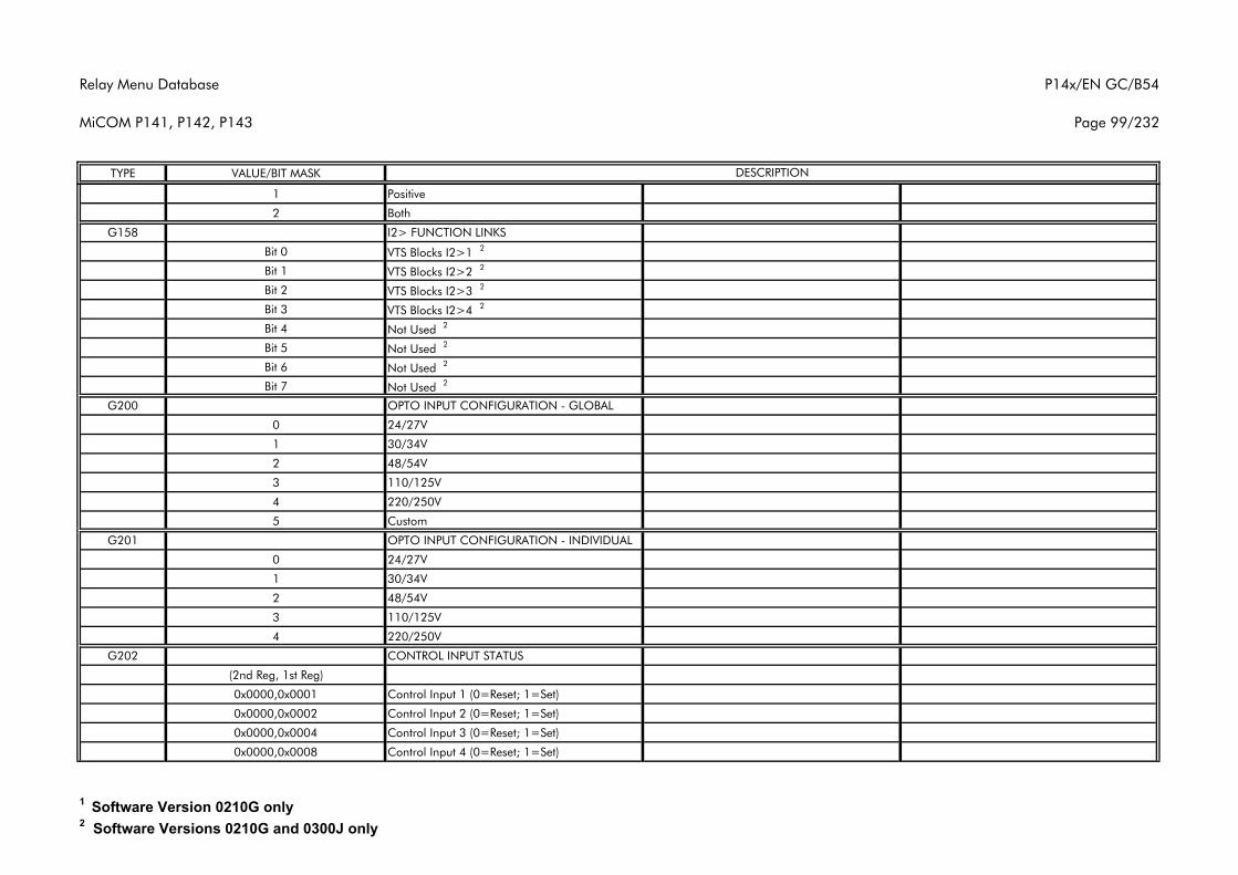
Relay Menu Database
MiCOM P141, P142, P143
P14x/EN GC/B54
Page 99/232
TYPE VALUE/BIT MASK DESCRIPTION
1 Positive
2 Both
G158 I2> FUNCTION LINKS
Bit 0 VTS Blocks I2>1 2
Bit 1 VTS Blocks I2>2 2
Bit 2 VTS Blocks I2>3 2
Bit 3 VTS Blocks I2>4 2
Bit 4 Not Used 2
Bit 5 Not Used 2
Bit 6 Not Used 2
Bit 7 Not Used 2
G200 OPTO INPUT CONFIGURATION - GLOBAL
0 24/27V
1 30/34V
2 48/54V
3 110/125V
4 220/250V
5 Custom
G201 OPTO INPUT CONFIGURATION - INDIVIDUAL
0 24/27V
1 30/34V
2 48/54V
3 110/125V
4 220/250V
G202 CONTROL INPUT STATUS
(2nd Reg, 1st Reg)
0x0000,0x0001 Control Input 1 (0=Reset; 1=Set)
0x0000,0x0002 Control Input 2 (0=Reset; 1=Set)
0x0000,0x0004 Control Input 3 (0=Reset; 1=Set)
0x0000,0x0008 Control Input 4 (0=Reset; 1=Set)
1 Software Version 0210G only2 Software Versions 0210G and 0300J only
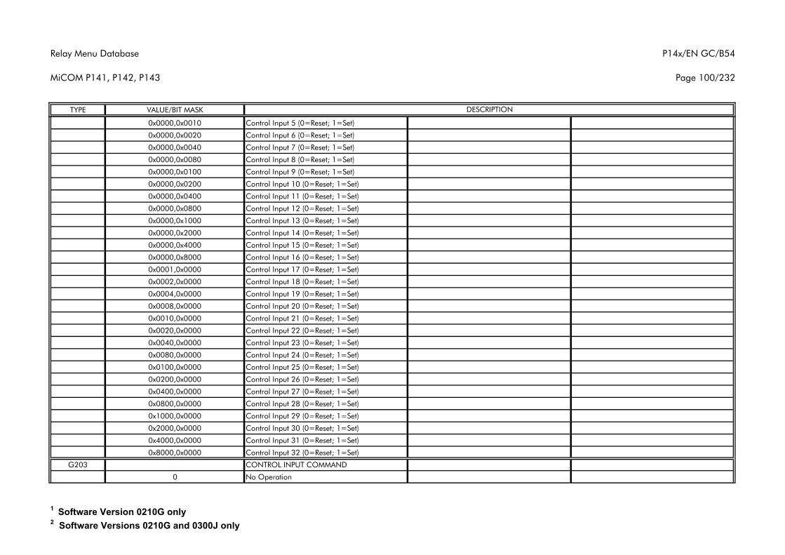
Relay Menu Database
MiCOM P141, P142, P143
P14x/EN GC/B54
Page 100/232
TYPE VALUE/BIT MASK DESCRIPTION
0x0000,0x0010 Control Input 5 (0=Reset; 1=Set)
0x0000,0x0020 Control Input 6 (0=Reset; 1=Set)
0x0000,0x0040 Control Input 7 (0=Reset; 1=Set)
0x0000,0x0080 Control Input 8 (0=Reset; 1=Set)
0x0000,0x0100 Control Input 9 (0=Reset; 1=Set)
0x0000,0x0200 Control Input 10 (0=Reset; 1=Set)
0x0000,0x0400 Control Input 11 (0=Reset; 1=Set)
0x0000,0x0800 Control Input 12 (0=Reset; 1=Set)
0x0000,0x1000 Control Input 13 (0=Reset; 1=Set)
0x0000,0x2000 Control Input 14 (0=Reset; 1=Set)
0x0000,0x4000 Control Input 15 (0=Reset; 1=Set)
0x0000,0x8000 Control Input 16 (0=Reset; 1=Set)
0x0001,0x0000 Control Input 17 (0=Reset; 1=Set)
0x0002,0x0000 Control Input 18 (0=Reset; 1=Set)
0x0004,0x0000 Control Input 19 (0=Reset; 1=Set)
0x0008,0x0000 Control Input 20 (0=Reset; 1=Set)
0x0010,0x0000 Control Input 21 (0=Reset; 1=Set)
0x0020,0x0000 Control Input 22 (0=Reset; 1=Set)
0x0040,0x0000 Control Input 23 (0=Reset; 1=Set)
0x0080,0x0000 Control Input 24 (0=Reset; 1=Set)
0x0100,0x0000 Control Input 25 (0=Reset; 1=Set)
0x0200,0x0000 Control Input 26 (0=Reset; 1=Set)
0x0400,0x0000 Control Input 27 (0=Reset; 1=Set)
0x0800,0x0000 Control Input 28 (0=Reset; 1=Set)
0x1000,0x0000 Control Input 29 (0=Reset; 1=Set)
0x2000,0x0000 Control Input 30 (0=Reset; 1=Set)
0x4000,0x0000 Control Input 31 (0=Reset; 1=Set)
0x8000,0x0000 Control Input 32 (0=Reset; 1=Set)
G203 CONTROL INPUT COMMAND
0 No Operation
1 Software Version 0210G only2 Software Versions 0210G and 0300J only
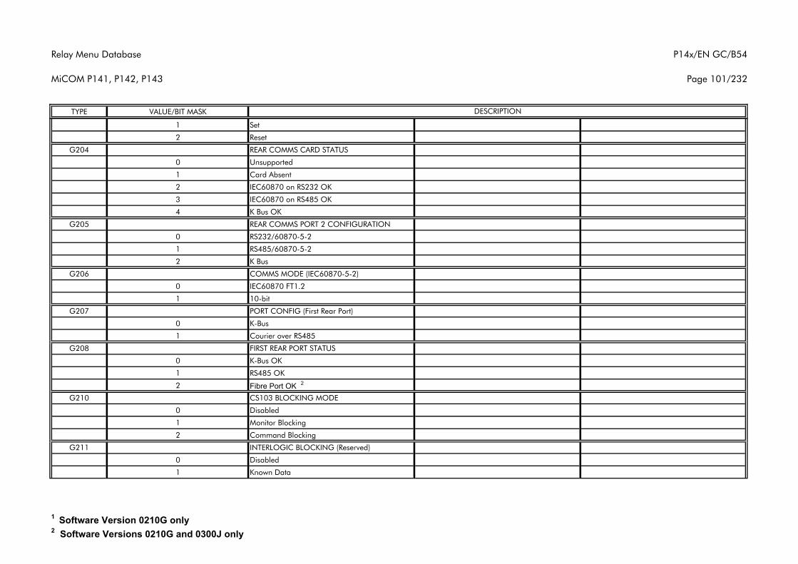
Relay Menu Database
MiCOM P141, P142, P143
P14x/EN GC/B54
Page 101/232
TYPE VALUE/BIT MASK DESCRIPTION
1 Set
2 Reset
G204 REAR COMMS CARD STATUS
0 Unsupported
1 Card Absent
2 IEC60870 on RS232 OK
3 IEC60870 on RS485 OK
4 K Bus OK
G205 REAR COMMS PORT 2 CONFIGURATION
0 RS232/60870-5-2
1 RS485/60870-5-2
2 K Bus
G206 COMMS MODE (IEC60870-5-2)
0 IEC60870 FT1.2
1 10-bit
G207 PORT CONFIG (First Rear Port)
0 K-Bus
1 Courier over RS485
G208 FIRST REAR PORT STATUS
0 K-Bus OK
1 RS485 OK
2 Fibre Port OK 2
G210 CS103 BLOCKING MODE
0 Disabled
1 Monitor Blocking
2 Command Blocking
G211 INTERLOGIC BLOCKING (Reserved)
0 Disabled
1 Known Data
1 Software Version 0210G only2 Software Versions 0210G and 0300J only
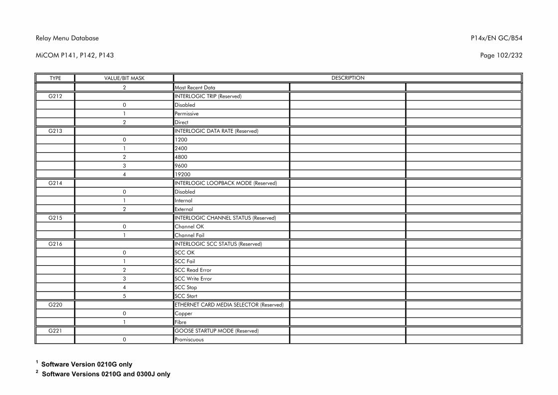
Relay Menu Database
MiCOM P141, P142, P143
P14x/EN GC/B54
Page 102/232
TYPE VALUE/BIT MASK DESCRIPTION
2 Most Recent Data
G212 INTERLOGIC TRIP (Reserved)
0 Disabled
1 Permissive
2 Direct
G213 INTERLOGIC DATA RATE (Reserved)
0 1200
1 2400
2 4800
3 9600
4 19200
G214 INTERLOGIC LOOPBACK MODE (Reserved)
0 Disabled
1 Internal
2 External
G215 INTERLOGIC CHANNEL STATUS (Reserved)
0 Channel OK
1 Channel Fail
G216 INTERLOGIC SCC STATUS (Reserved)
0 SCC OK
1 SCC Fail
2 SCC Read Error
3 SCC Write Error
4 SCC Stop
5 SCC Start
G220 ETHERNET CARD MEDIA SELECTOR (Reserved)
0 Copper
1 Fibre
G221 GOOSE STARTUP MODE (Reserved)
0 Promiscuous
1 Software Version 0210G only2 Software Versions 0210G and 0300J only
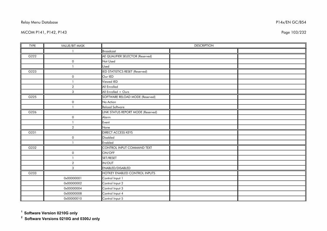
Relay Menu Database
MiCOM P141, P142, P143
P14x/EN GC/B54
Page 103/232
TYPE VALUE/BIT MASK DESCRIPTION
1 Broadcast
G222 AE QUALIFIER SELECTOR (Reserved)
0 Not Used
1 Used
G223 IED STATISTICS RESET (Reserved)
0 Our IED
1 Viewed IED
2 All Enrolled
3 All Enrolled + Ours
G225 SOFTWARE RELOAD MODE (Reserved)
0 No Action
1 Reload Software
G226 LINK STATUS REPORT MODE (Reserved)
0 Alarm
1 Event
2 None
G231 DIRECT ACCESS KEYS
0 Disabled
1 Enabled
G232 CONTROL INPUT COMMAND TEXT
0 ON/OFF
1 SET/RESET
2 IN/OUT
3 ENABLED/DISABLED
G233 HOTKEY ENABLED CONTROL INPUTS
0x00000001 Control Input 1
0x00000002 Control Input 2
0x00000004 Control Input 3
0x00000008 Control Input 4
0x00000010 Control Input 5
1 Software Version 0210G only2 Software Versions 0210G and 0300J only
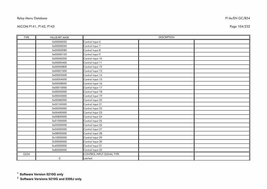
Relay Menu Database
MiCOM P141, P142, P143
P14x/EN GC/B54
Page 104/232
TYPE VALUE/BIT MASK DESCRIPTION
0x00000020 Control Input 6
0x00000040 Control Input 7
0x00000080 Control Input 8
0x00000100 Control Input 9
0x00000200 Control Input 10
0x00000400 Control Input 11
0x00000800 Control Input 12
0x00001000 Control Input 13
0x00002000 Control Input 14
0x00004000 Control Input 15
0x00008000 Control Input 16
0x00010000 Control Input 17
0x00020000 Control Input 18
0x00040000 Control Input 19
0x00080000 Control Input 20
0x00100000 Control Input 21
0x00200000 Control Input 22
0x00400000 Control Input 23
0x00800000 Control Input 24
0x01000000 Control Input 25
0x02000000 Control Input 26
0x04000000 Control Input 27
0x08000000 Control Input 28
0x10000000 Control Input 29
0x20000000 Control Input 30
0x40000000 Control Input 31
0x80000000 Control Input 32
G234 CONTROL INPUT SIGNAL TYPE
0 Latched
1 Software Version 0210G only2 Software Versions 0210G and 0300J only
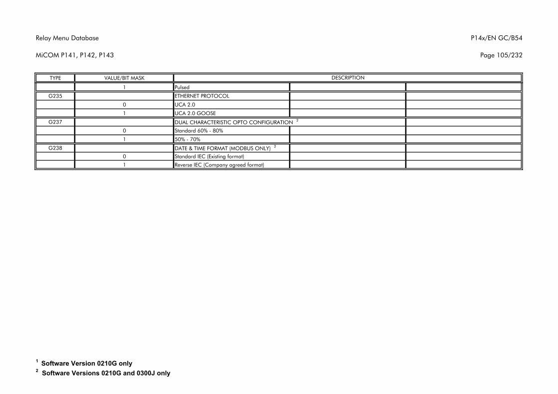
Relay Menu Database
MiCOM P141, P142, P143
P14x/EN GC/B54
Page 105/232
TYPE VALUE/BIT MASK DESCRIPTION
1 Pulsed
G235 ETHERNET PROTOCOL
0 UCA 2.0
1 UCA 2.0 GOOSE
G237 DUAL CHARACTERISTIC OPTO CONFIGURATION 2
0 Standard 60% - 80%
1 50% - 70%
G238 DATE & TIME FORMAT (MODBUS ONLY) 2
0 Standard IEC (Existing format)
1 Reverse IEC (Company agreed format)
1 Software Version 0210G only2 Software Versions 0210G and 0300J only
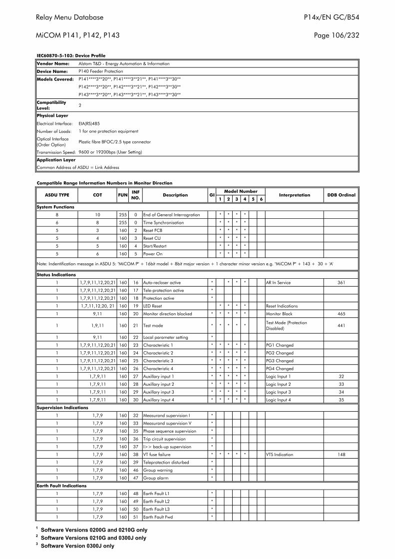
Relay Menu Database
MiCOM P141, P142, P143
P14x/EN GC/B54
Page 106/232
Vendor Name:
Device Name:
Models Covered:
Compatibility Level:
2
Electrical Interface: EIA(RS)485
Number of Loads:
Optical Interface (Order Option)
Plastic fibre BFOC/2.5 type connector
Transmission Speed:
1 2 3 4 5 6
8 10 255 0 End of General Interrogration * * * *
6 8 255 0 Time Synchronisation * * * *
5 3 160 2 Reset FCB * * * *
5 4 160 3 Reset CU * * * *
5 5 160 4 Start/Restart * * * *
5 6 160 5 Power On * * * *
1 1,7,9,11,12,20,21 160 16 Auto-recloser active * * * * AR In Service 361
1 1,7,9,11,12,20,21 160 17 Tele-protection active *
1 1,7,9,11,12,20,21 160 18 Protection active *
1 1,7,11,12,20, 21 160 19 LED Reset * * * * Reset Indications
1 9,11 160 20 Monitor direction blocked * * * * * Monitor Block 465
1 1,9,11 160 21 Test mode * * * * *Test Mode (Protection Disabled)
441
1 9,11 160 22 Local parameter setting *
1 1,7,9,11,12,20,21 160 23 Characteristic 1 * * * * * PG1 Changed
1 1,7,9,11,12,20,21 160 24 Characteristic 2 * * * * * PG2 Changed
1 1,7,9,11,12,20,21 160 25 Characteristic 3 * * * * * PG3 Changed
1 1,7,9,11,12,20,21 160 26 Characteristic 4 * * * * * PG4 Changed
1 1,7,9,11 160 27 Auxillary input 1 * * * * * Logic Input 1 32
1 1,7,9,11 160 28 Auxillary input 2 * * * * * Logic Input 2 33
1 1,7,9,11 160 29 Auxillary input 3 * * * * * Logic Input 3 34
1 1,7,9,11 160 30 Auxillary input 4 * * * * * Logic Input 4 35
1 1,7,9 160 32 Measurand supervision I *
1 1,7,9 160 33 Measurand supervision V *
1 1,7,9 160 35 Phase sequence supervision *
1 1,7,9 160 36 Trip circuit supervision *
1 1,7,9 160 37 I>> back-up supervision *
1 1,7,9 160 38 VT fuse failure * * * * * VTS Indication 148
1 1,7,9 160 39 Teleprotection disturbed *
1 1,7,9 160 46 Group warning *
1 1,7,9 160 47 Group alarm *
1 1,7,9 160 48 Earth Fault L1 *
1 1,7,9 160 49 Earth Fault L2 *
1 1,7,9 160 50 Earth Fault L3 *
1 1,7,9 160 51 Earth Fault Fwd *
Status Indications
COT FUN
P143****3**20**, P143****3**21**, P143****3**30**
Supervision Indications
1 for one protection equipment
9600 or 19200bps (User Setting)
Common Address of ASDU = Link Address
Application Layer
Compatible Range Information Numbers in Monitor Direction
IEC60870-5-103: Device Profile
Alstom T&D - Energy Automation & Information
P140 Feeder Protection
Physical Layer
P141****3**20**, P141****3**21**, P141****3**30**
P142****3**20**, P142****3**21**, P142****3**30**
Note: Indentification message in ASDU 5: "MiCOM P" + 16bit model + 8bit major version + 1 character minor version e.g. "MiCOM P" + 143 + 30 + 'A'
Description
System Functions
ASDU TYPE
Earth Fault Indications
INF NO.
DDB OrdinalGI InterpretationModel Number
1 Software Versions 0200G and 0210G only2 Software Versions 0210G and 0300J only3 Software Version 0300J only
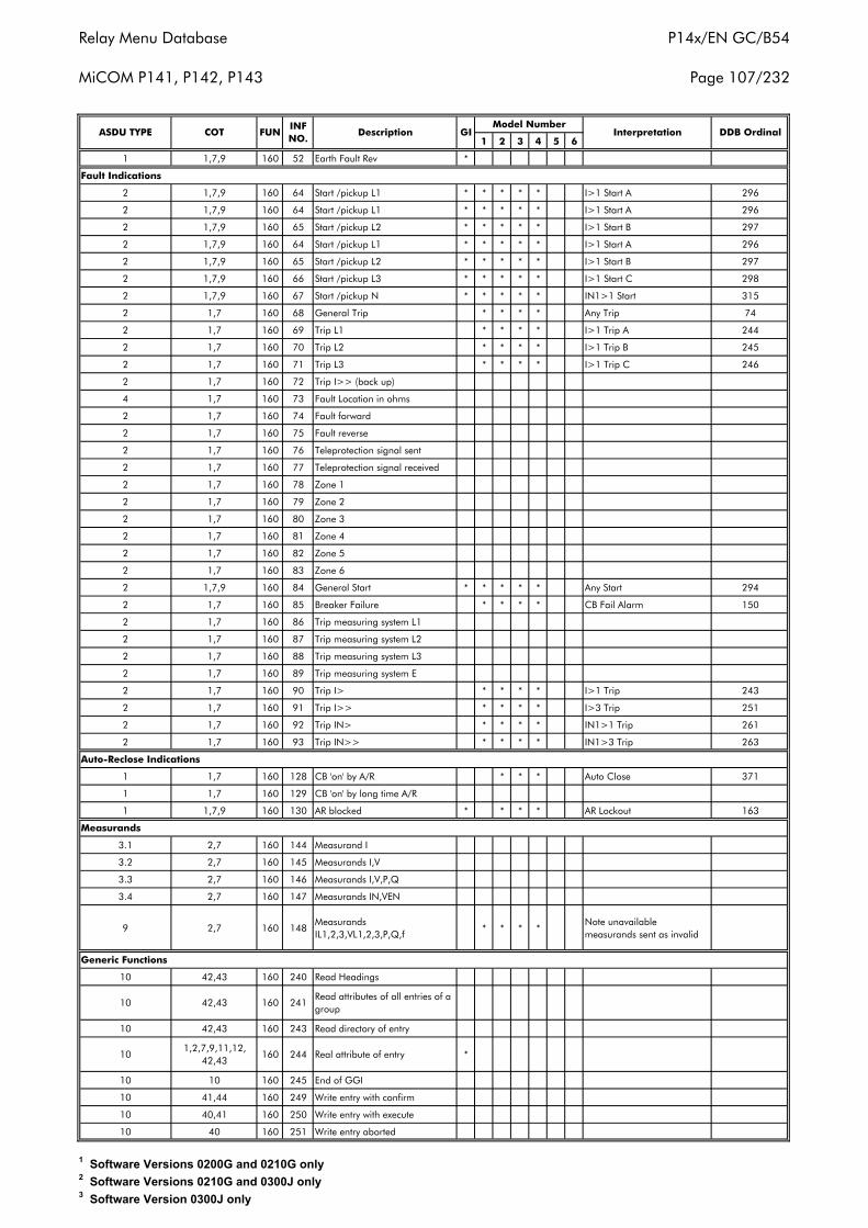
Relay Menu Database
MiCOM P141, P142, P143
P14x/EN GC/B54
Page 107/232
1 2 3 4 5 6
1 1,7,9 160 52 Earth Fault Rev *
Fault Indications
2 1,7,9 160 64 Start /pickup L1 * * * * * I>1 Start A 296
2 1,7,9 160 64 Start /pickup L1 * * * * * I>1 Start A 296
2 1,7,9 160 65 Start /pickup L2 * * * * * I>1 Start B 297
2 1,7,9 160 64 Start /pickup L1 * * * * * I>1 Start A 296
2 1,7,9 160 65 Start /pickup L2 * * * * * I>1 Start B 297
2 1,7,9 160 66 Start /pickup L3 * * * * * I>1 Start C 298
2 1,7,9 160 67 Start /pickup N * * * * * IN1>1 Start 315
2 1,7 160 68 General Trip * * * * Any Trip 74
2 1,7 160 69 Trip L1 * * * * I>1 Trip A 244
2 1,7 160 70 Trip L2 * * * * I>1 Trip B 245
2 1,7 160 71 Trip L3 * * * * I>1 Trip C 246
2 1,7 160 72 Trip I>> (back up)
4 1,7 160 73 Fault Location in ohms
2 1,7 160 74 Fault forward
2 1,7 160 75 Fault reverse
2 1,7 160 76 Teleprotection signal sent
2 1,7 160 77 Teleprotection signal received
2 1,7 160 78 Zone 1
2 1,7 160 79 Zone 2
2 1,7 160 80 Zone 3
2 1,7 160 81 Zone 4
2 1,7 160 82 Zone 5
2 1,7 160 83 Zone 6
2 1,7,9 160 84 General Start * * * * * Any Start 294
2 1,7 160 85 Breaker Failure * * * * CB Fail Alarm 150
2 1,7 160 86 Trip measuring system L1
2 1,7 160 87 Trip measuring system L2
2 1,7 160 88 Trip measuring system L3
2 1,7 160 89 Trip measuring system E
2 1,7 160 90 Trip I> * * * * I>1 Trip 243
2 1,7 160 91 Trip I>> * * * * I>3 Trip 251
2 1,7 160 92 Trip IN> * * * * IN1>1 Trip 261
2 1,7 160 93 Trip IN>> * * * * IN1>3 Trip 263
1 1,7 160 128 CB 'on' by A/R * * * Auto Close 371
1 1,7 160 129 CB 'on' by long time A/R
1 1,7,9 160 130 AR blocked * * * * AR Lockout 163
Measurands
3.1 2,7 160 144 Measurand I
3.2 2,7 160 145 Measurands I,V
3.3 2,7 160 146 Measurands I,V,P,Q
3.4 2,7 160 147 Measurands IN,VEN
9 2,7 160 148Measurands IL1,2,3,VL1,2,3,P,Q,f
* * * *Note unavailable measurands sent as invalid
Generic Functions
10 42,43 160 240 Read Headings
10 42,43 160 241Read attributes of all entries of a group
10 42,43 160 243 Read directory of entry
101,2,7,9,11,12,
42,43160 244 Real attribute of entry *
10 10 160 245 End of GGI
10 41,44 160 249 Write entry with confirm
10 40,41 160 250 Write entry with execute
10 40 160 251 Write entry aborted
Auto-Reclose Indications
ASDU TYPE COT FUNINF NO.
Description GIModel Number
Interpretation DDB Ordinal
1 Software Versions 0200G and 0210G only2 Software Versions 0210G and 0300J only3 Software Version 0300J only
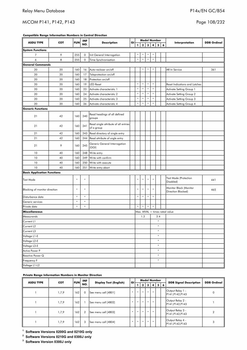
Relay Menu Database
MiCOM P141, P142, P143
P14x/EN GC/B54
Page 108/232
1 2 3 4 5 6
7 9 255 0 Init General Interrogation * * * *
6 8 255 0 Time Synchronisation * * * *
20 20 160 16 Auto-recloser on/off * * * AR In Service 361
20 20 160 17 Teleprotection on/off
20 20 160 18 Protection on/off
20 20 160 19 LED Reset * * * * Reset Indications and Latches
20 20 160 23 Activate characteristic 1 * * * * Activate Setting Group 1
20 20 160 24 Activate characteristic 2 * * * * Activate Setting Group 2
20 20 160 25 Activate characteristic 3 * * * * Activate Setting Group 3
20 20 160 26 Activate characteristic 4 * * * * Activate Setting Group 4
21 42 160 240Read headings of all defined groups
21 42 160 241Read single attribute of all entries of a group
21 42 160 243 Read directory of single entry
21 42 160 244 Read attribute of sngle entry
21 9 160 245Generic General Interrogation (GGI)
10 40 160 248 Write entry
10 40 160 249 Write with confirm
10 40 160 250 Write with execute
10 40 160 251 Write entry abort
* * * * * *Test Mode (Protection Disabled)
441
* * * * * *Monitor Block (Monitor Direction Blocked)
465
* * * * * *
* *
* * * * * *
Miscellaneous Max. MVAL = times rated value
1 2 3 4 5 6
1 1,7,9 162 0 See menu cell [4B01] * * * * *Output Relay 1 - P141,P142,P143
0
1 1,7,9 162 1 See menu cell [4B02] * * * * *Output Relay 2 - P141,P142,P143
1
1 1,7,9 162 2 See menu cell [4B03] * * * * *Output Relay 3 - P141,P142,P143
2
1 1,7,9 162 3 See menu cell [4B04] * * * * *Output Relay 4 - P141,P142,P143
3
*
*
*
*
*
*
*
Voltage L3-E
Reactive Power Q
Voltage L2-E
Active Power P
2.4
Current L1
Measurands
Frequency F
Current L3
Voltage L1-E
Voltage L1-L2
Generic services
Private data
Compatible Range Information Numbers in Control Direction
Disturbance data
ASDU TYPE COT FUNINF NO.
Test Mode
System Functions
General Commands
Blocking of monitor direction
1.2
Generic Functions
*
*
GI DDB Signal DescriptionModel Number
DDB OrdinalDescription GI InterpretationModel Number
DDB OrdinalDisplay Text (English)INF NO.
FUN
Basic Application Functions
Private Range Information Numbers in Monitor Direction
COTASDU TYPE
Current L2
1 Software Versions 0200G and 0210G only2 Software Versions 0210G and 0300J only3 Software Version 0300J only
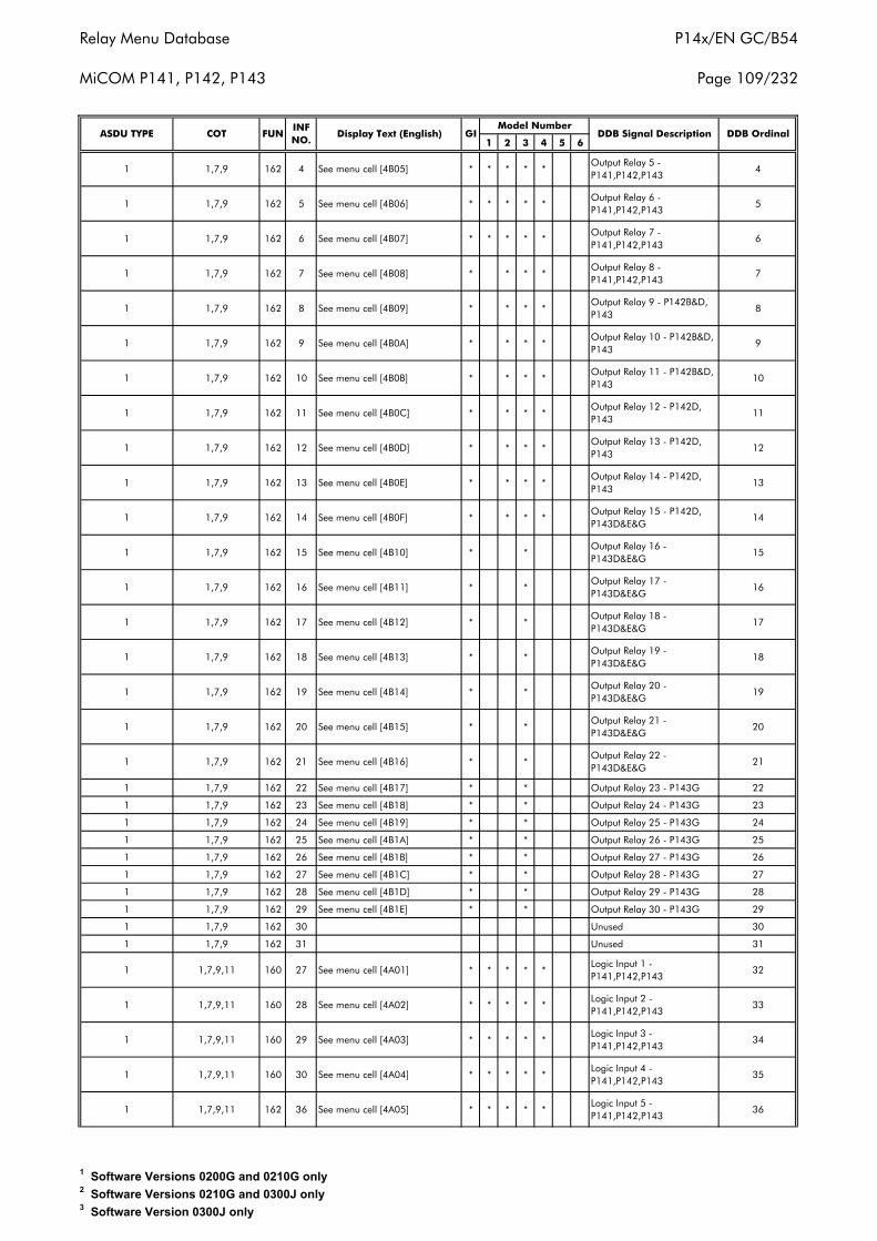
Relay Menu Database
MiCOM P141, P142, P143
P14x/EN GC/B54
Page 109/232
1 2 3 4 5 6
1 1,7,9 162 4 See menu cell [4B05] * * * * *Output Relay 5 - P141,P142,P143
4
1 1,7,9 162 5 See menu cell [4B06] * * * * *Output Relay 6 - P141,P142,P143
5
1 1,7,9 162 6 See menu cell [4B07] * * * * *Output Relay 7 - P141,P142,P143
6
1 1,7,9 162 7 See menu cell [4B08] * * * *Output Relay 8 - P141,P142,P143
7
1 1,7,9 162 8 See menu cell [4B09] * * * *Output Relay 9 - P142B&D, P143
8
1 1,7,9 162 9 See menu cell [4B0A] * * * *Output Relay 10 - P142B&D, P143
9
1 1,7,9 162 10 See menu cell [4B0B] * * * *Output Relay 11 - P142B&D, P143
10
1 1,7,9 162 11 See menu cell [4B0C] * * * *Output Relay 12 - P142D, P143
11
1 1,7,9 162 12 See menu cell [4B0D] * * * *Output Relay 13 - P142D, P143
12
1 1,7,9 162 13 See menu cell [4B0E] * * * *Output Relay 14 - P142D, P143
13
1 1,7,9 162 14 See menu cell [4B0F] * * * *Output Relay 15 - P142D, P143D&E&G
14
1 1,7,9 162 15 See menu cell [4B10] * *Output Relay 16 - P143D&E&G
15
1 1,7,9 162 16 See menu cell [4B11] * *Output Relay 17 - P143D&E&G
16
1 1,7,9 162 17 See menu cell [4B12] * *Output Relay 18 - P143D&E&G
17
1 1,7,9 162 18 See menu cell [4B13] * *Output Relay 19 - P143D&E&G
18
1 1,7,9 162 19 See menu cell [4B14] * *Output Relay 20 - P143D&E&G
19
1 1,7,9 162 20 See menu cell [4B15] * *Output Relay 21 - P143D&E&G
20
1 1,7,9 162 21 See menu cell [4B16] * *Output Relay 22 - P143D&E&G
21
1 1,7,9 162 22 See menu cell [4B17] * * Output Relay 23 - P143G 22
1 1,7,9 162 23 See menu cell [4B18] * * Output Relay 24 - P143G 23
1 1,7,9 162 24 See menu cell [4B19] * * Output Relay 25 - P143G 24
1 1,7,9 162 25 See menu cell [4B1A] * * Output Relay 26 - P143G 25
1 1,7,9 162 26 See menu cell [4B1B] * * Output Relay 27 - P143G 26
1 1,7,9 162 27 See menu cell [4B1C] * * Output Relay 28 - P143G 27
1 1,7,9 162 28 See menu cell [4B1D] * * Output Relay 29 - P143G 28
1 1,7,9 162 29 See menu cell [4B1E] * * Output Relay 30 - P143G 29
1 1,7,9 162 30 Unused 30
1 1,7,9 162 31 Unused 31
1 1,7,9,11 160 27 See menu cell [4A01] * * * * *Logic Input 1 - P141,P142,P143
32
1 1,7,9,11 160 28 See menu cell [4A02] * * * * *Logic Input 2 - P141,P142,P143
33
1 1,7,9,11 160 29 See menu cell [4A03] * * * * *Logic Input 3 - P141,P142,P143
34
1 1,7,9,11 160 30 See menu cell [4A04] * * * * *Logic Input 4 - P141,P142,P143
35
1 1,7,9,11 162 36 See menu cell [4A05] * * * * *Logic Input 5 - P141,P142,P143
36
Model NumberDDB Signal DescriptionDisplay Text (English) GI DDB Ordinal
INF NO.
FUNASDU TYPE COT
1 Software Versions 0200G and 0210G only2 Software Versions 0210G and 0300J only3 Software Version 0300J only
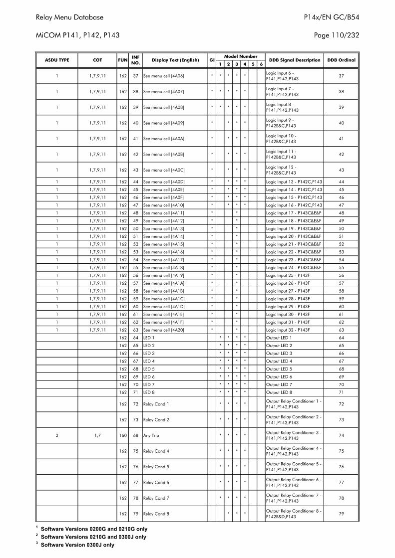
Relay Menu Database
MiCOM P141, P142, P143
P14x/EN GC/B54
Page 110/232
1 2 3 4 5 6
1 1,7,9,11 162 37 See menu cell [4A06] * * * * *Logic Input 6 - P141,P142,P143
37
1 1,7,9,11 162 38 See menu cell [4A07] * * * * *Logic Input 7 - P141,P142,P143
38
1 1,7,9,11 162 39 See menu cell [4A08] * * * * *Logic Input 8 - P141,P142,P143
39
1 1,7,9,11 162 40 See menu cell [4A09] * * * *Logic Input 9 - P142B&C,P143
40
1 1,7,9,11 162 41 See menu cell [4A0A] * * * *Logic Input 10 - P142B&C,P143
41
1 1,7,9,11 162 42 See menu cell [4A0B] * * * *Logic Input 11 - P142B&C,P143
42
1 1,7,9,11 162 43 See menu cell [4A0C] * * * *Logic Input 12 - P142B&C,P143
43
1 1,7,9,11 162 44 See menu cell [4A0D] * * * * Logic Input 13 - P142C,P143 44
1 1,7,9,11 162 45 See menu cell [4A0E] * * * * Logic Input 14 - P142C,P143 45
1 1,7,9,11 162 46 See menu cell [4A0F] * * * * Logic Input 15 - P142C,P143 46
1 1,7,9,11 162 47 See menu cell [4A10] * * * * Logic Input 16 - P142C,P143 47
1 1,7,9,11 162 48 See menu cell [4A11] * * Logic Input 17 - P143C&E&F 48
1 1,7,9,11 162 49 See menu cell [4A12] * * Logic Input 18 - P143C&E&F 49
1 1,7,9,11 162 50 See menu cell [4A13] * * Logic Input 19 - P143C&E&F 50
1 1,7,9,11 162 51 See menu cell [4A14] * * Logic Input 20 - P143C&E&F 51
1 1,7,9,11 162 52 See menu cell [4A15] * * Logic Input 21 - P143C&E&F 52
1 1,7,9,11 162 53 See menu cell [4A16] * * Logic Input 22 - P143C&E&F 53
1 1,7,9,11 162 54 See menu cell [4A17] * * Logic Input 23 - P143C&E&F 54
1 1,7,9,11 162 55 See menu cell [4A18] * * Logic Input 24 - P143C&E&F 55
1 1,7,9,11 162 56 See menu cell [4A19] * * Logic Input 25 - P143F 56
1 1,7,9,11 162 57 See menu cell [4A1A] * * Logic Input 26 - P143F 57
1 1,7,9,11 162 58 See menu cell [4A1B] * * Logic Input 27 - P143F 58
1 1,7,9,11 162 59 See menu cell [4A1C] * * Logic Input 28 - P143F 59
1 1,7,9,11 162 60 See menu cell [4A1D] * * Logic Input 29 - P143F 60
1 1,7,9,11 162 61 See menu cell [4A1E] * * Logic Input 30 - P143F 61
1 1,7,9,11 162 62 See menu cell [4A1F] * * Logic Input 31 - P143F 62
1 1,7,9,11 162 63 See menu cell [4A20] * * Logic Input 32 - P143F 63
162 64 LED 1 * * * * Output LED 1 64
162 65 LED 2 * * * * Output LED 2 65
162 66 LED 3 * * * * Output LED 3 66
162 67 LED 4 * * * * Output LED 4 67
162 68 LED 5 * * * * Output LED 5 68
162 69 LED 6 * * * * Output LED 6 69
162 70 LED 7 * * * * Output LED 7 70
162 71 LED 8 * * * * Output LED 8 71
162 72 Relay Cond 1 * * * *Output Relay Conditioner 1 - P141,P142,P143
72
162 73 Relay Cond 2 * * * *Output Relay Conditioner 2 - P141,P142,P143
73
2 1,7 160 68 Any Trip * * * *Output Relay Conditioner 3 - P141,P142,P143
74
162 75 Relay Cond 4 * * * *Output Relay Conditioner 4 - P141,P142,P143
75
162 76 Relay Cond 5 * * * *Output Relay Conditioner 5 - P141,P142,P143
76
162 77 Relay Cond 6 * * * *Output Relay Conditioner 6 - P141,P142,P143
77
162 78 Relay Cond 7 * * * *Output Relay Conditioner 7 - P141,P142,P143
78
162 79 Relay Cond 8 * * *Output Relay Conditioner 8 - P142B&D,P143
79
DDB OrdinalDisplay Text (English) GIModel Number
DDB Signal DescriptionASDU TYPE COT FUNINF NO.
1 Software Versions 0200G and 0210G only2 Software Versions 0210G and 0300J only3 Software Version 0300J only
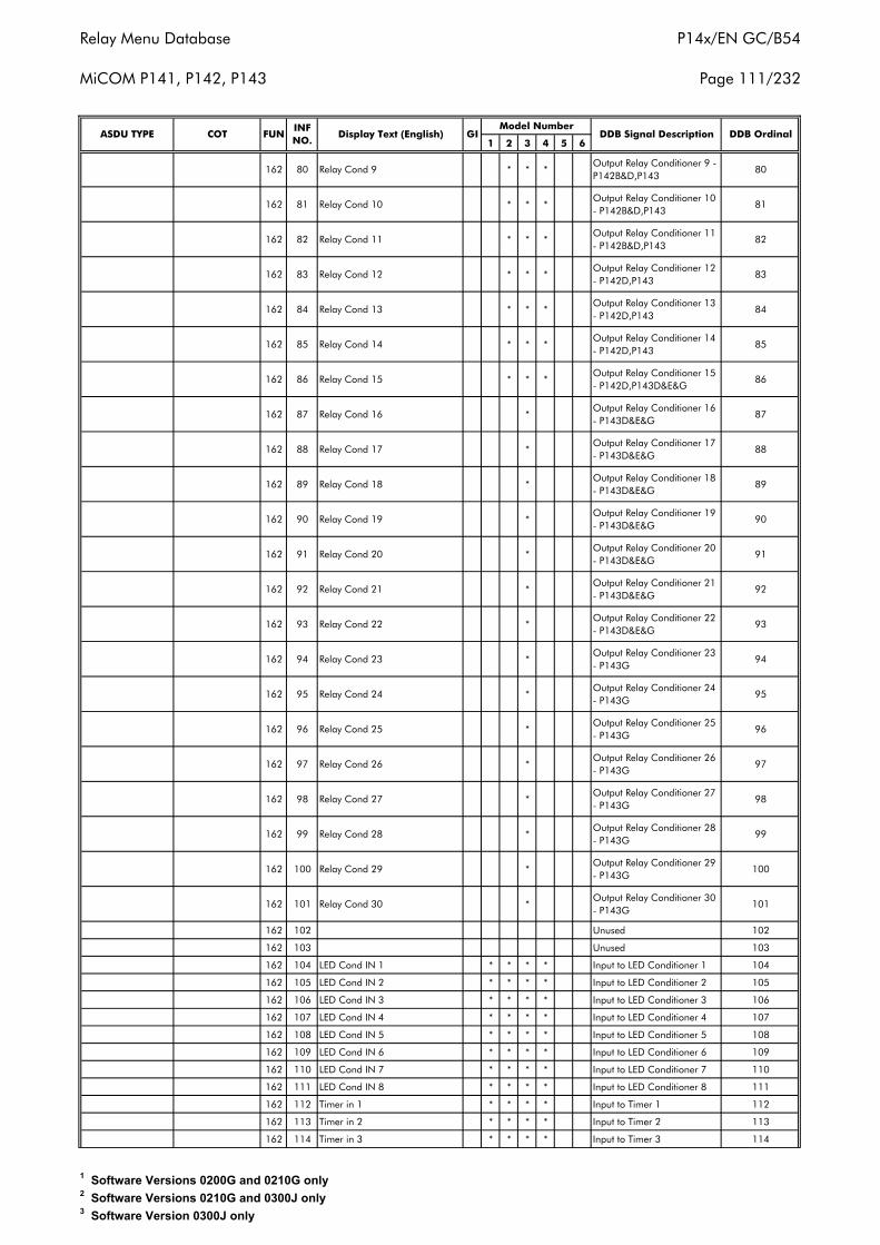
Relay Menu Database
MiCOM P141, P142, P143
P14x/EN GC/B54
Page 111/232
1 2 3 4 5 6
162 80 Relay Cond 9 * * *Output Relay Conditioner 9 - P142B&D,P143
80
162 81 Relay Cond 10 * * *Output Relay Conditioner 10 - P142B&D,P143
81
162 82 Relay Cond 11 * * *Output Relay Conditioner 11 - P142B&D,P143
82
162 83 Relay Cond 12 * * *Output Relay Conditioner 12 - P142D,P143
83
162 84 Relay Cond 13 * * *Output Relay Conditioner 13 - P142D,P143
84
162 85 Relay Cond 14 * * *Output Relay Conditioner 14 - P142D,P143
85
162 86 Relay Cond 15 * * *Output Relay Conditioner 15 - P142D,P143D&E&G
86
162 87 Relay Cond 16 *Output Relay Conditioner 16 - P143D&E&G
87
162 88 Relay Cond 17 *Output Relay Conditioner 17 - P143D&E&G
88
162 89 Relay Cond 18 *Output Relay Conditioner 18 - P143D&E&G
89
162 90 Relay Cond 19 *Output Relay Conditioner 19 - P143D&E&G
90
162 91 Relay Cond 20 *Output Relay Conditioner 20 - P143D&E&G
91
162 92 Relay Cond 21 *Output Relay Conditioner 21 - P143D&E&G
92
162 93 Relay Cond 22 *Output Relay Conditioner 22 - P143D&E&G
93
162 94 Relay Cond 23 *Output Relay Conditioner 23 - P143G
94
162 95 Relay Cond 24 *Output Relay Conditioner 24 - P143G
95
162 96 Relay Cond 25 *Output Relay Conditioner 25 - P143G
96
162 97 Relay Cond 26 *Output Relay Conditioner 26 - P143G
97
162 98 Relay Cond 27 *Output Relay Conditioner 27 - P143G
98
162 99 Relay Cond 28 *Output Relay Conditioner 28 - P143G
99
162 100 Relay Cond 29 *Output Relay Conditioner 29 - P143G
100
162 101 Relay Cond 30 *Output Relay Conditioner 30 - P143G
101
162 102 Unused 102
162 103 Unused 103
162 104 LED Cond IN 1 * * * * Input to LED Conditioner 1 104
162 105 LED Cond IN 2 * * * * Input to LED Conditioner 2 105
162 106 LED Cond IN 3 * * * * Input to LED Conditioner 3 106
162 107 LED Cond IN 4 * * * * Input to LED Conditioner 4 107
162 108 LED Cond IN 5 * * * * Input to LED Conditioner 5 108
162 109 LED Cond IN 6 * * * * Input to LED Conditioner 6 109
162 110 LED Cond IN 7 * * * * Input to LED Conditioner 7 110
162 111 LED Cond IN 8 * * * * Input to LED Conditioner 8 111
162 112 Timer in 1 * * * * Input to Timer 1 112
162 113 Timer in 2 * * * * Input to Timer 2 113
162 114 Timer in 3 * * * * Input to Timer 3 114
DDB Signal Description DDB OrdinalINF NO.
Display Text (English) GIModel Number
ASDU TYPE COT FUN
1 Software Versions 0200G and 0210G only2 Software Versions 0210G and 0300J only3 Software Version 0300J only
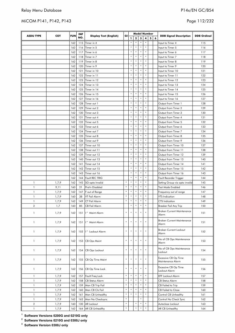
Relay Menu Database
MiCOM P141, P142, P143
P14x/EN GC/B54
Page 112/232
1 2 3 4 5 6
162 115 Timer in 4 * * * * Input to Timer 4 115
162 116 Timer in 5 * * * * Input to Timer 5 116
162 117 Timer in 6 * * * * Input to Timer 6 117
162 118 Timer in 7 * * * * Input to Timer 7 118
162 119 Timer in 8 * * * * Input to Timer 8 119
162 120 Timer in 9 * * * * Input to Timer 9 120
162 121 Timer in 10 * * * * Input to Timer 10 121
162 122 Timer in 11 * * * * Input to Timer 11 122
162 123 Timer in 12 * * * * Input to Timer 12 123
162 124 Timer in 13 * * * * Input to Timer 13 124
162 125 Timer in 14 * * * * Input to Timer 14 125
162 126 Timer in 15 * * * * Input to Timer 15 126
162 127 Timer in 16 * * * * Input to Timer 16 127
162 128 Timer out 1 * * * * Output from Timer 1 128
162 129 Timer out 2 * * * * Output from Timer 2 129
162 130 Timer out 3 * * * * Output from Timer 3 130
162 131 Timer out 4 * * * * Output from Timer 4 131
162 132 Timer out 5 * * * * Output from Timer 5 132
162 133 Timer out 6 * * * * Output from Timer 6 133
162 134 Timer out 7 * * * * Output from Timer 7 134
162 135 Timer out 8 * * * * Output from Timer 8 135
162 136 Timer out 9 * * * * Output from Timer 9 136
162 137 Timer out 10 * * * * Output from Timer 10 137
162 138 Timer out 11 * * * * Output from Timer 11 138
162 139 Timer out 12 * * * * Output from Timer 12 139
162 140 Timer out 13 * * * * Output from Timer 13 140
162 141 Timer out 14 * * * * Output from Timer 14 141
162 142 Timer out 15 * * * * Output from Timer 15 142
162 143 Timer out 16 * * * * Output from Timer 16 143
162 144 Fault REC TRIG * * * * Fault Recorder Trigger 144
1 1,7,9 162 145 SG-opto Invalid * * * * * Setting Group via opto invalid 145
1 9,11 160 21 Prot'n Disabled * * * * * Test Mode Enabled 146
1 1,7,9 162 147 F out of Range * * * * * Frequency out of range 147
1 1,7,9 160 38 VT Fail Alarm * * * * * VTS Indication 148
1 1,7,9 162 149 CT Fail Alarm * * * * * CTS Indication 149
2 1,7 160 85 CB Fail Alarm * * * * Breaker Fail Any Trip 150
1 1,7,9 162 151 I^ Maint Alarm * * * * *Broken Current Maintenance Alarm
151
1 1,7,9 162 151 I^ Maint Alarm * * * * *Broken Current Maintenance Alarm
151
1 1,7,9 162 152 I^ Lockout Alarm * * * * *Broken Current Lockout Alarm
152
1 1,7,9 162 153 CB Ops Maint * * * * *No of CB Ops Maintenance Alarm
153
1 1,7,9 162 154 CB Ops Lockout * * * * *No of CB Ops Maintenance Lockout
154
1 1,7,9 162 155 CB Op Time Maint * * * * *Excessive CB Op Time Maintenance Alarm
155
1 1,7,9 162 156 CB Op Time Lock * * * * *Excessive CB Op Time Lockout Alarm
156
1 1,7,9 162 157 Fault Freq Lock * * * * * EFF Lockout Alarm 157
1 1,7,9 162 158 CB Status Alarm * * * * * CB Status Alarm 158
1 1,7,9 162 159 Man CB Trip Fail * * * * * CB Failed to Trip 159
1 1,7.9 162 160 Man CB Cls Fail * * * * * CB Failed to Close 160
1 1,7,9 162 161 Man CB Unhealthy * * * * * Control CB Unhealthy 161
1 1,7,9 162 162 Man No Checksync * * Control No Check Sync 162
2 1,7,9 160 130 AR Lockout * * * * Autoclose Lockout 163
1 1,7,9 162 164 AR CB Unhealthy * * * * AR CB Unhealthy 164
ASDU TYPE COT FUNINF NO.
Display Text (English) GIModel Number
DDB Signal Description DDB Ordinal
1 Software Versions 0200G and 0210G only2 Software Versions 0210G and 0300J only3 Software Version 0300J only
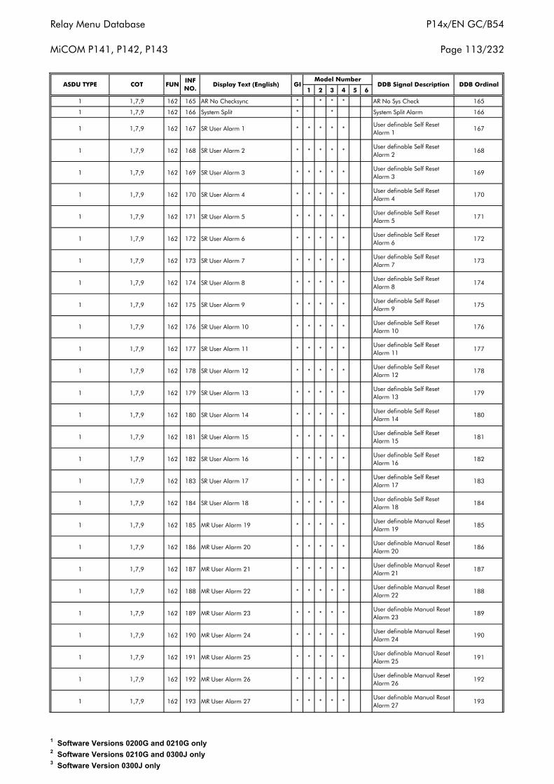
Relay Menu Database
MiCOM P141, P142, P143
P14x/EN GC/B54
Page 113/232
1 2 3 4 5 6
1 1,7,9 162 165 AR No Checksync * * * * AR No Sys Check 165
1 1,7,9 162 166 System Split * * System Split Alarm 166
1 1,7,9 162 167 SR User Alarm 1 * * * * *User definable Self Reset Alarm 1
167
1 1,7,9 162 168 SR User Alarm 2 * * * * *User definable Self Reset Alarm 2
168
1 1,7,9 162 169 SR User Alarm 3 * * * * *User definable Self Reset Alarm 3
169
1 1,7,9 162 170 SR User Alarm 4 * * * * *User definable Self Reset Alarm 4
170
1 1,7,9 162 171 SR User Alarm 5 * * * * *User definable Self Reset Alarm 5
171
1 1,7,9 162 172 SR User Alarm 6 * * * * *User definable Self Reset Alarm 6
172
1 1,7,9 162 173 SR User Alarm 7 * * * * *User definable Self Reset Alarm 7
173
1 1,7,9 162 174 SR User Alarm 8 * * * * *User definable Self Reset Alarm 8
174
1 1,7,9 162 175 SR User Alarm 9 * * * * *User definable Self Reset Alarm 9
175
1 1,7,9 162 176 SR User Alarm 10 * * * * *User definable Self Reset Alarm 10
176
1 1,7,9 162 177 SR User Alarm 11 * * * * *User definable Self Reset Alarm 11
177
1 1,7,9 162 178 SR User Alarm 12 * * * * *User definable Self Reset Alarm 12
178
1 1,7,9 162 179 SR User Alarm 13 * * * * *User definable Self Reset Alarm 13
179
1 1,7,9 162 180 SR User Alarm 14 * * * * *User definable Self Reset Alarm 14
180
1 1,7,9 162 181 SR User Alarm 15 * * * * *User definable Self Reset Alarm 15
181
1 1,7,9 162 182 SR User Alarm 16 * * * * *User definable Self Reset Alarm 16
182
1 1,7,9 162 183 SR User Alarm 17 * * * * *User definable Self Reset Alarm 17
183
1 1,7,9 162 184 SR User Alarm 18 * * * * *User definable Self Reset Alarm 18
184
1 1,7,9 162 185 MR User Alarm 19 * * * * *User definable Manual Reset Alarm 19
185
1 1,7,9 162 186 MR User Alarm 20 * * * * *User definable Manual Reset Alarm 20
186
1 1,7,9 162 187 MR User Alarm 21 * * * * *User definable Manual Reset Alarm 21
187
1 1,7,9 162 188 MR User Alarm 22 * * * * *User definable Manual Reset Alarm 22
188
1 1,7,9 162 189 MR User Alarm 23 * * * * *User definable Manual Reset Alarm 23
189
1 1,7,9 162 190 MR User Alarm 24 * * * * *User definable Manual Reset Alarm 24
190
1 1,7,9 162 191 MR User Alarm 25 * * * * *User definable Manual Reset Alarm 25
191
1 1,7,9 162 192 MR User Alarm 26 * * * * *User definable Manual Reset Alarm 26
192
1 1,7,9 162 193 MR User Alarm 27 * * * * *User definable Manual Reset Alarm 27
193
Display Text (English) GIModel Number
DDB Signal DescriptionASDU TYPE COT FUNINF NO.
DDB Ordinal
1 Software Versions 0200G and 0210G only2 Software Versions 0210G and 0300J only3 Software Version 0300J only
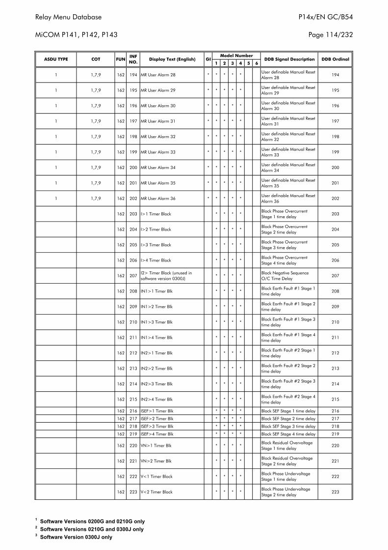
Relay Menu Database
MiCOM P141, P142, P143
P14x/EN GC/B54
Page 114/232
1 2 3 4 5 6
1 1,7,9 162 194 MR User Alarm 28 * * * * *User definable Manual Reset Alarm 28
194
1 1,7,9 162 195 MR User Alarm 29 * * * * *User definable Manual Reset Alarm 29
195
1 1,7,9 162 196 MR User Alarm 30 * * * * *User definable Manual Reset Alarm 30
196
1 1,7,9 162 197 MR User Alarm 31 * * * * *User definable Manual Reset Alarm 31
197
1 1,7,9 162 198 MR User Alarm 32 * * * * *User definable Manual Reset Alarm 32
198
1 1,7,9 162 199 MR User Alarm 33 * * * * *User definable Manual Reset Alarm 33
199
1 1,7,9 162 200 MR User Alarm 34 * * * * *User definable Manual Reset Alarm 34
200
1 1,7,9 162 201 MR User Alarm 35 * * * * *User definable Manual Reset Alarm 35
201
1 1,7,9 162 202 MR User Alarm 36 * * * * *User definable Manual Reset Alarm 36
202
162 203 I>1 Timer Block * * * *Block Phase Overcurrent Stage 1 time delay
203
162 204 I>2 Timer Block * * * *Block Phase Overcurrent Stage 2 time delay
204
162 205 I>3 Timer Block * * * *Block Phase Overcurrent Stage 3 time delay
205
162 206 I>4 Timer Block * * * *Block Phase Overcurrent Stage 4 time delay
206
162 207I2> Timer Block (unused in software version 0300J)
* * * *Block Negative Sequence O/C Time Delay
207
162 208 IN1>1 Timer Blk * * * *Block Earth Fault #1 Stage 1 time delay
208
162 209 IN1>2 Timer Blk * * * *Block Earth Fault #1 Stage 2 time delay
209
162 210 IN1>3 Timer Blk * * * *Block Earth Fault #1 Stage 3 time delay
210
162 211 IN1>4 Timer Blk * * * *Block Earth Fault #1 Stage 4 time delay
211
162 212 IN2>1 Timer Blk * * * *Block Earth Fault #2 Stage 1 time delay
212
162 213 IN2>2 Timer Blk * * * *Block Earth Fault #2 Stage 2 time delay
213
162 214 IN2>3 Timer Blk * * * *Block Earth Fault #2 Stage 3 time delay
214
162 215 IN2>4 Timer Blk * * * *Block Earth Fault #2 Stage 4 time delay
215
162 216 ISEF>1 Timer Blk * * * * Block SEF Stage 1 time delay 216
162 217 ISEF>2 Timer Blk * * * * Block SEF Stage 2 time delay 217
162 218 ISEF>3 Timer Blk * * * * Block SEF Stage 3 time delay 218
162 219 ISEF>4 Timer Blk * * * * Block SEF Stage 4 time delay 219
162 220 VN>1 Timer Blk * * * *Block Residual Overvoltage Stage 1 time delay
220
162 221 VN>2 Timer Blk * * * *Block Residual Overvoltage Stage 2 time delay
221
162 222 V<1 Timer Block * * * *Block Phase Undervoltage Stage 1 time delay
222
162 223 V<2 Timer Block * * * *Block Phase Undervoltage Stage 2 time delay
223
Display Text (English) GIModel Number
DDB Signal DescriptionASDU TYPE COT FUNINF NO.
DDB Ordinal
1 Software Versions 0200G and 0210G only2 Software Versions 0210G and 0300J only3 Software Version 0300J only
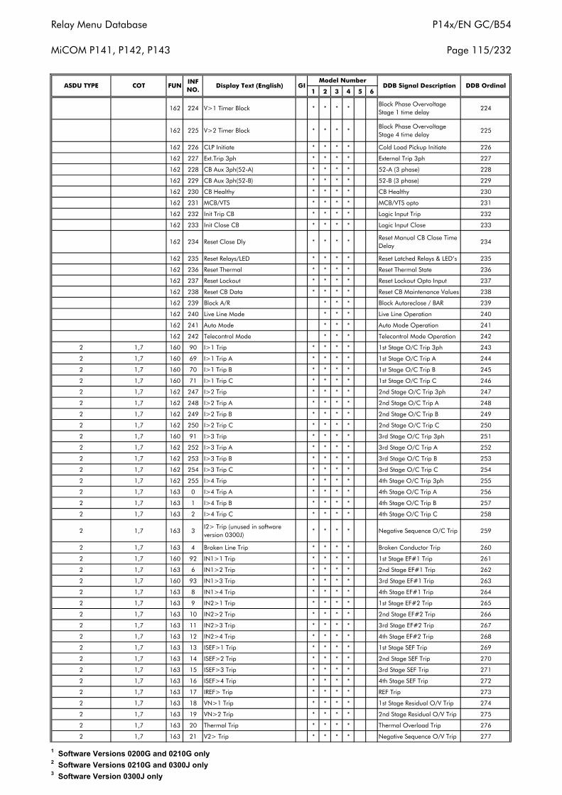
Relay Menu Database
MiCOM P141, P142, P143
P14x/EN GC/B54
Page 115/232
1 2 3 4 5 6
162 224 V>1 Timer Block * * * *Block Phase Overvoltage Stage 1 time delay
224
162 225 V>2 Timer Block * * * *Block Phase Overvoltage Stage 4 time delay
225
162 226 CLP Initiate * * * * Cold Load Pickup Initiate 226
162 227 Ext.Trip 3ph * * * * External Trip 3ph 227
162 228 CB Aux 3ph(52-A) * * * * 52-A (3 phase) 228
162 229 CB Aux 3ph(52-B) * * * * 52-B (3 phase) 229
162 230 CB Healthy * * * * CB Healthy 230
162 231 MCB/VTS * * * * MCB/VTS opto 231
162 232 Init Trip CB * * * * Logic Input Trip 232
162 233 Init Close CB * * * * Logic Input Close 233
162 234 Reset Close Dly * * * *Reset Manual CB Close Time Delay
234
162 235 Reset Relays/LED * * * * Reset Latched Relays & LED’s 235
162 236 Reset Thermal * * * * Reset Thermal State 236
162 237 Reset Lockout * * * * Reset Lockout Opto Input 237
162 238 Reset CB Data * * * * Reset CB Maintenance Values 238
162 239 Block A/R * * * Block Autoreclose / BAR 239
162 240 Live Line Mode * * * Live Line Operation 240
162 241 Auto Mode * * * Auto Mode Operation 241
162 242 Telecontrol Mode * * * Telecontrol Mode Operation 242
2 1,7 160 90 I>1 Trip * * * * 1st Stage O/C Trip 3ph 243
2 1,7 160 69 I>1 Trip A * * * * 1st Stage O/C Trip A 244
2 1,7 160 70 I>1 Trip B * * * * 1st Stage O/C Trip B 245
2 1,7 160 71 I>1 Trip C * * * * 1st Stage O/C Trip C 246
2 1,7 162 247 I>2 Trip * * * * 2nd Stage O/C Trip 3ph 247
2 1,7 162 248 I>2 Trip A * * * * 2nd Stage O/C Trip A 248
2 1,7 162 249 I>2 Trip B * * * * 2nd Stage O/C Trip B 249
2 1,7 162 250 I>2 Trip C * * * * 2nd Stage O/C Trip C 250
2 1,7 160 91 I>3 Trip * * * * 3rd Stage O/C Trip 3ph 251
2 1,7 162 252 I>3 Trip A * * * * 3rd Stage O/C Trip A 252
2 1,7 162 253 I>3 Trip B * * * * 3rd Stage O/C Trip B 253
2 1,7 162 254 I>3 Trip C * * * * 3rd Stage O/C Trip C 254
2 1,7 162 255 I>4 Trip * * * * 4th Stage O/C Trip 3ph 255
2 1,7 163 0 I>4 Trip A * * * * 4th Stage O/C Trip A 256
2 1,7 163 1 I>4 Trip B * * * * 4th Stage O/C Trip B 257
2 1,7 163 2 I>4 Trip C * * * * 4th Stage O/C Trip C 258
2 1,7 163 3I2> Trip (unused in software version 0300J)
* * * * Negative Sequence O/C Trip 259
2 1,7 163 4 Broken Line Trip * * * * Broken Conductor Trip 260
2 1,7 160 92 IN1>1 Trip * * * * 1st Stage EF#1 Trip 261
2 1,7 163 6 IN1>2 Trip * * * * 2nd Stage EF#1 Trip 262
2 1,7 160 93 IN1>3 Trip * * * * 3rd Stage EF#1 Trip 263
2 1,7 163 8 IN1>4 Trip * * * * 4th Stage EF#1 Trip 264
2 1,7 163 9 IN2>1 Trip * * * * 1st Stage EF#2 Trip 265
2 1,7 163 10 IN2>2 Trip * * * * 2nd Stage EF#2 Trip 266
2 1,7 163 11 IN2>3 Trip * * * * 3rd Stage EF#2 Trip 267
2 1,7 163 12 IN2>4 Trip * * * * 4th Stage EF#2 Trip 268
2 1,7 163 13 ISEF>1 Trip * * * * 1st Stage SEF Trip 269
2 1,7 163 14 ISEF>2 Trip * * * * 2nd Stage SEF Trip 270
2 1,7 163 15 ISEF>3 Trip * * * * 3rd Stage SEF Trip 271
2 1,7 163 16 ISEF>4 Trip * * * * 4th Stage SEF Trip 272
2 1,7 163 17 IREF> Trip * * * * REF Trip 273
2 1,7 163 18 VN>1 Trip * * * * 1st Stage Residual O/V Trip 274
2 1,7 163 19 VN>2 Trip * * * * 2nd Stage Residual O/V Trip 275
2 1,7 163 20 Thermal Trip * * * * Thermal Overload Trip 276
2 1,7 163 21 V2> Trip * * * * Negative Sequence O/V Trip 277
Display Text (English) GIModel Number
DDB Signal Description DDB OrdinalASDU TYPE COT FUNINF NO.
1 Software Versions 0200G and 0210G only2 Software Versions 0210G and 0300J only3 Software Version 0300J only
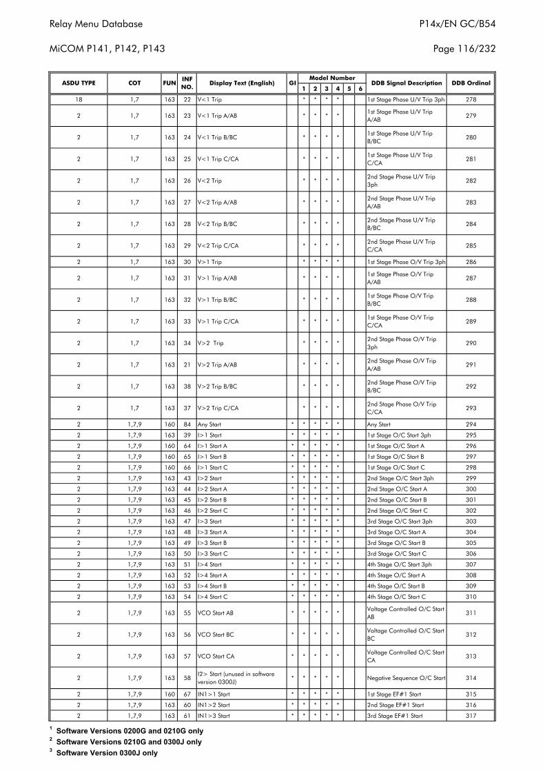
Relay Menu Database
MiCOM P141, P142, P143
P14x/EN GC/B54
Page 116/232
1 2 3 4 5 6
18 1,7 163 22 V<1 Trip * * * * 1st Stage Phase U/V Trip 3ph 278
2 1,7 163 23 V<1 Trip A/AB * * * *1st Stage Phase U/V Trip A/AB
279
2 1,7 163 24 V<1 Trip B/BC * * * *1st Stage Phase U/V Trip B/BC
280
2 1,7 163 25 V<1 Trip C/CA * * * *1st Stage Phase U/V Trip C/CA
281
2 1,7 163 26 V<2 Trip * * * *2nd Stage Phase U/V Trip 3ph
282
2 1,7 163 27 V<2 Trip A/AB * * * *2nd Stage Phase U/V Trip A/AB
283
2 1,7 163 28 V<2 Trip B/BC * * * *2nd Stage Phase U/V Trip B/BC
284
2 1,7 163 29 V<2 Trip C/CA * * * *2nd Stage Phase U/V Trip C/CA
285
2 1,7 163 30 V>1 Trip * * * * 1st Stage Phase O/V Trip 3ph 286
2 1,7 163 31 V>1 Trip A/AB * * * *1st Stage Phase O/V Trip A/AB
287
2 1,7 163 32 V>1 Trip B/BC * * * *1st Stage Phase O/V Trip B/BC
288
2 1,7 163 33 V>1 Trip C/CA * * * *1st Stage Phase O/V Trip C/CA
289
2 1,7 163 34 V>2 Trip * * * *2nd Stage Phase O/V Trip 3ph
290
2 1,7 163 21 V>2 Trip A/AB * * * *2nd Stage Phase O/V Trip A/AB
291
2 1,7 163 38 V>2 Trip B/BC * * * *2nd Stage Phase O/V Trip B/BC
292
2 1,7 163 37 V>2 Trip C/CA * * * *2nd Stage Phase O/V Trip C/CA
293
2 1,7,9 160 84 Any Start * * * * * Any Start 294
2 1,7,9 163 39 I>1 Start * * * * * 1st Stage O/C Start 3ph 295
2 1,7,9 160 64 I>1 Start A * * * * * 1st Stage O/C Start A 296
2 1,7,9 160 65 I>1 Start B * * * * * 1st Stage O/C Start B 297
2 1,7,9 160 66 I>1 Start C * * * * * 1st Stage O/C Start C 298
2 1,7,9 163 43 I>2 Start * * * * * 2nd Stage O/C Start 3ph 299
2 1,7,9 163 44 I>2 Start A * * * * * 2nd Stage O/C Start A 300
2 1,7,9 163 45 I>2 Start B * * * * * 2nd Stage O/C Start B 301
2 1,7,9 163 46 I>2 Start C * * * * * 2nd Stage O/C Start C 302
2 1,7,9 163 47 I>3 Start * * * * * 3rd Stage O/C Start 3ph 303
2 1,7,9 163 48 I>3 Start A * * * * * 3rd Stage O/C Start A 304
2 1,7,9 163 49 I>3 Start B * * * * * 3rd Stage O/C Start B 305
2 1,7,9 163 50 I>3 Start C * * * * * 3rd Stage O/C Start C 306
2 1,7,9 163 51 I>4 Start * * * * * 4th Stage O/C Start 3ph 307
2 1,7,9 163 52 I>4 Start A * * * * * 4th Stage O/C Start A 308
2 1,7,9 163 53 I>4 Start B * * * * * 4th Stage O/C Start B 309
2 1,7,9 163 54 I>4 Start C * * * * * 4th Stage O/C Start C 310
2 1,7,9 163 55 VCO Start AB * * * * *Voltage Controlled O/C Start AB
311
2 1,7,9 163 56 VCO Start BC * * * * *Voltage Controlled O/C Start BC
312
2 1,7,9 163 57 VCO Start CA * * * * *Voltage Controlled O/C Start CA
313
2 1,7,9 163 58I2> Start (unused in software version 0300J)
* * * * * Negative Sequence O/C Start 314
2 1,7,9 160 67 IN1>1 Start * * * * * 1st Stage EF#1 Start 315
2 1,7,9 163 60 IN1>2 Start * * * * * 2nd Stage EF#1 Start 316
2 1,7,9 163 61 IN1>3 Start * * * * * 3rd Stage EF#1 Start 317
ASDU TYPE COT FUNINF NO.
Display Text (English) GIModel Number
DDB Signal Description DDB Ordinal
1 Software Versions 0200G and 0210G only2 Software Versions 0210G and 0300J only3 Software Version 0300J only
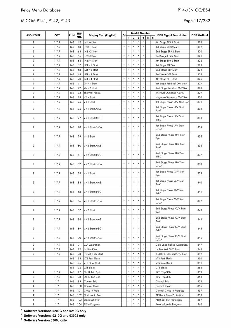
Relay Menu Database
MiCOM P141, P142, P143
P14x/EN GC/B54
Page 117/232
1 2 3 4 5 6
2 1,7,9 163 62 IN1>4 Start * * * * * 4th Stage EF#1 Start 318
2 1,7,9 163 63 IN2>1 Start * * * * * 1st Stage EF#2 Start 319
2 1,7,9 163 64 IN2>2 Start * * * * * 2nd Stage EF#2 Start 320
2 1,7,9 163 65 IN2>3 Start * * * * * 3rd Stage EF#2 Start 321
2 1,7,9 163 66 IN2>4 Start * * * * * 4th Stage EF#2 Start 322
2 1,7,9 163 67 ISEF>1 Start * * * * * 1st Stage SEF Start 323
2 1,7,9 163 68 ISEF>2 Start * * * * * 2nd Stage SEF Start 324
2 1,7,9 163 69 ISEF>3 Start * * * * * 3rd Stage SEF Start 325
2 1,7,9 163 70 ISEF>4 Start * * * * * 4th Stage SEF Start 326
2 1,7,9 163 71 VN>1 Start * * * * * 1st Stage Residual O/V Start 327
2 1,7,9 163 72 VN>2 Start * * * * * 2nd Stage Residual O/V Start 328
2 1,7,9 163 73 Thermal Alarm * * * * * Thermal Overload Alarm 329
2 1,7,9 163 74 V2> Start * * * * * Negative Sequence O/V Start 330
2 1,7,9 163 75 V<1 Start * * * * * 1st Stage Phase U/V Start 3ph 331
2 1,7,9 163 76 V<1 Start A/AB * * * * *1st Stage Phase U/V Start A/AB
332
2 1,7,9 163 77 V<1 Start B/BC * * * * *1st Stage Phase U/V Start B/BC
333
2 1,7,9 163 78 V<1 Start C/CA * * * * *1st Stage Phase U/V Start C/CA
334
2 1,7,9 163 79 V<2 Start * * * * *2nd Stage Phase U/V Start 3ph
335
2 1,7,9 163 80 V<2 Start A/AB * * * * *2nd Stage Phase U/V Start A/AB
336
2 1,7,9 163 81 V<2 Start B/BC * * * * *2nd Stage Phase U/V Start B/BC
337
2 1,7,9 163 82 V<2 Start C/CA * * * * *2nd Stage Phase U/V Start C/CA
338
2 1,7,9 163 83 V>1 Start * * * * *1st Stage Phase O/V Start 3ph
339
2 1,7,9 163 84 V>1 Start A/AB * * * * *1st Stage Phase O/V Start A/AB
340
2 1,7,9 163 85 V>1 Start B/BC * * * * *1st Stage Phase O/V Start B/BC
341
2 1,7,9 163 86 V>1 Start C/CA * * * * *1st Stage Phase O/V Start C/CA
342
2 1,7,9 163 87 V>2 Start * * * * *2nd Stage Phase O/V Start 3ph
343
2 1,7,9 163 88 V>2 Start A/AB * * * * *2nd Stage Phase O/V Start A/AB
344
2 1,7,9 163 89 V>2 Start B/BC * * * * *2nd Stage Phase O/V Start B/BC
345
2 1,7,9 163 90 V>2 Start C/CA * * * * *2nd Stage Phase O/V Start C/CA
346
2 1,7,9 163 91 CLP Operation * * * * * Cold Load Pickup Operation 347
2 1,7,9 163 92 I> BlockStart * * * * * I> Blocked O/C Start 348
2 1,7,9 163 93 IN/SEF>Blk Start * * * * * IN/ISEF> Blocked O/C Start 349
163 94 VTS Fast Block * * * * VTS Fast Block 350
163 95 VTS Slow Block * * * * VTS Slow Block 351
163 96 CTS Block * * * * CTS Block 352
2 1,7,9 163 97 Bfail1 Trip 3ph * * * * tBF1 Trip 3Ph 353
2 1,7,9 163 98 Bfail2 Trip 3ph * * * * tBF2 Trip 3Ph 354
1 1,7 163 99 Control Trip * * * * Control Trip 355
1 1,7 163 100 Control Close * * * * Control Close 356
1 1,7 163 101 Close in Prog * * * * Control Close in Progress 357
1 1,7 163 102 Block Main Prot * * * AR Block Main Protection 358
1 1,7 163 103 Block SEF Prot * * * AR Block SEF Protection 359
1 1,7 163 104 AR In Progress * * * Autoreclose In Progress 360
Display Text (English) GIModel Number
DDB Signal DescriptionASDU TYPE COT FUNINF NO.
DDB Ordinal
1 Software Versions 0200G and 0210G only2 Software Versions 0210G and 0300J only3 Software Version 0300J only
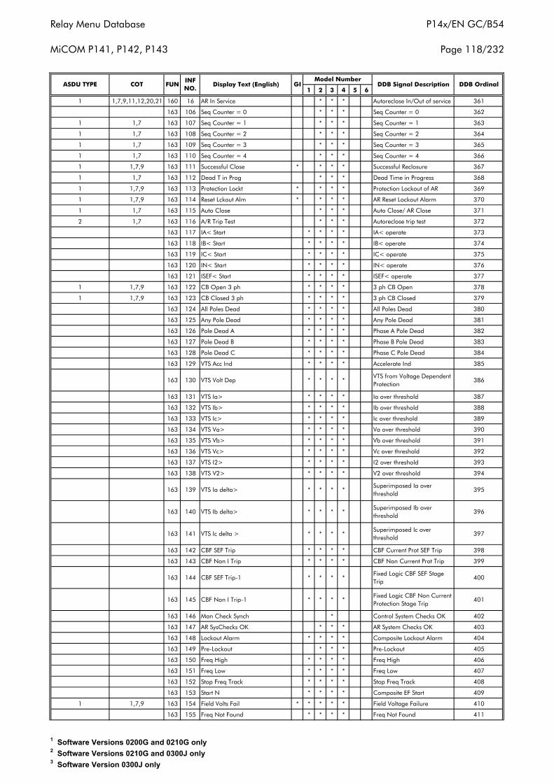
Relay Menu Database
MiCOM P141, P142, P143
P14x/EN GC/B54
Page 118/232
1 2 3 4 5 6
1 1,7,9,11,12,20,21 160 16 AR In Service * * * Autoreclose In/Out of service 361
163 106 Seq Counter = 0 * * * Seq Counter = 0 362
1 1,7 163 107 Seq Counter = 1 * * * Seq Counter = 1 363
1 1,7 163 108 Seq Counter = 2 * * * Seq Counter = 2 364
1 1,7 163 109 Seq Counter = 3 * * * Seq Counter = 3 365
1 1,7 163 110 Seq Counter = 4 * * * Seq Counter = 4 366
1 1,7,9 163 111 Successful Close * * * * Successful Reclosure 367
1 1,7 163 112 Dead T in Prog * * * Dead Time in Progress 368
1 1,7,9 163 113 Protection Lockt * * * * Protection Lockout of AR 369
1 1,7,9 163 114 Reset Lckout Alm * * * * AR Reset Lockout Alarm 370
1 1,7 163 115 Auto Close * * * Auto Close/ AR Close 371
2 1,7 163 116 A/R Trip Test * * * Autoreclose trip test 372
163 117 IA< Start * * * * IA< operate 373
163 118 IB< Start * * * * IB< operate 374
163 119 IC< Start * * * * IC< operate 375
163 120 IN< Start * * * * IN< operate 376
163 121 ISEF< Start * * * * ISEF< operate 377
1 1,7,9 163 122 CB Open 3 ph * * * * 3 ph CB Open 378
1 1,7,9 163 123 CB Closed 3 ph * * * * 3 ph CB Closed 379
163 124 All Poles Dead * * * * All Poles Dead 380
163 125 Any Pole Dead * * * * Any Pole Dead 381
163 126 Pole Dead A * * * * Phase A Pole Dead 382
163 127 Pole Dead B * * * * Phase B Pole Dead 383
163 128 Pole Dead C * * * * Phase C Pole Dead 384
163 129 VTS Acc Ind * * * * Accelerate Ind 385
163 130 VTS Volt Dep * * * *VTS from Voltage Dependent Protection
386
163 131 VTS Ia> * * * * Ia over threshold 387
163 132 VTS Ib> * * * * Ib over threshold 388
163 133 VTS Ic> * * * * Ic over threshold 389
163 134 VTS Va> * * * * Va over threshold 390
163 135 VTS Vb> * * * * Vb over threshold 391
163 136 VTS Vc> * * * * Vc over threshold 392
163 137 VTS I2> * * * * I2 over threshold 393
163 138 VTS V2> * * * * V2 over threshold 394
163 139 VTS Ia delta> * * * *Superimposed Ia over threshold
395
163 140 VTS Ib delta> * * * *Superimposed Ib over threshold
396
163 141 VTS Ic delta > * * * *Superimposed Ic over threshold
397
163 142 CBF SEF Trip * * * * CBF Current Prot SEF Trip 398
163 143 CBF Non I Trip * * * * CBF Non Current Prot Trip 399
163 144 CBF SEF Trip-1 * * * *Fixed Logic CBF SEF Stage Trip
400
163 145 CBF Non I Trip-1 * * * *Fixed Logic CBF Non Current Protection Stage Trip
401
163 146 Man Check Synch * Control System Checks OK 402
163 147 AR SysChecks OK * * * AR System Checks OK 403
163 148 Lockout Alarm * * * * Composite Lockout Alarm 404
163 149 Pre-Lockout * * * Pre-Lockout 405
163 150 Freq High * * * * Freq High 406
163 151 Freq Low * * * * Freq Low 407
163 152 Stop Freq Track * * * * Stop Freq Track 408
163 153 Start N * * * * Composite EF Start 409
1 1,7,9 163 154 Field Volts Fail * * * * * Field Voltage Failure 410
163 155 Freq Not Found * * * * Freq Not Found 411
Display Text (English) GIModel Number
DDB Signal DescriptionASDU TYPE COT FUNINF NO.
DDB Ordinal
1 Software Versions 0200G and 0210G only2 Software Versions 0210G and 0300J only3 Software Version 0300J only
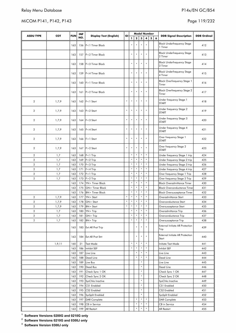
Relay Menu Database
MiCOM P141, P142, P143
P14x/EN GC/B54
Page 119/232
1 2 3 4 5 6
163 156 F<1 Timer Block * * * *Block Underfrequency Stage 1 Timer
412
163 157 F<2 Timer Block * * * *Block Underfrequency Stage 2 Timer
413
163 158 F<3 Timer Block * * * *Block Underfrequency Stage 3 Timer
414
163 159 F<4 Timer Block * * * *Block Underfrequency Stage 4 Timer
415
163 160 F>1 Timer Block * * * *Block Overfrequency Stage 1 Timer
416
163 161 F>2 Timer Block * * * *Block Overfrequency Stage 2 Timer
417
2 1,7,9 163 162 F<1 Start * * * * *Under frequency Stage 1 START
418
2 1,7,9 163 163 F<2 Start * * * * *Under frequency Stage 2 START
419
2 1,7,9 163 164 F<3 Start * * * * *Under frequency Stage 3 START
420
2 1,7,9 163 165 F<4 Start * * * * *Under frequency Stage 4 START
421
2 1,7,9 163 166 F>1 Start * * * * *Over frequency Stage 1 START
422
2 1,7,9 163 167 F>2 Start * * * * *Over frequency Stage 2 START
423
2 1,7 163 168 F<1 Trip * * * * Under frequency Stage 1 trip 424
2 1,7 163 169 F<2 Trip * * * * Under frequency Stage 2 trip 425
2 1,7 163 170 F<3 Trip * * * * Under frequency Stage 3 trip 426
2 1,7 163 171 F<4 Trip * * * * Under frequency Stage 4 trip 427
2 1,7 163 172 F>1 Trip * * * * Over frequency Stage 1 Trip 428
2 1,7 163 173 F>2 Trip * * * * Over frequency Stage 2 Trip 429
163 174 YN> Timer Block * * * * Block Overadmittance Timer 430
163 175 GN> Timer Block * * * * Block Overconductance Timer 431
163 176 BN> Timer Block * * * * Block Oversusceptance Timer 432
2 1,7,9 163 177 YN> Start * * * * * Overadmittance Start 433
2 1,7,9 163 178 GN> Start * * * * * Overconductance Start 434
2 1,7,9 163 179 BN> Start * * * * * Oversusceptance Start 435
2 1,7 163 180 YN> Trip * * * * Overadmittance Trip 436
2 1,7 163 181 GN> Trip * * * * Overconductance Trip 437
2 1,7 163 182 BN> Trip * * * * Oversusceptance Trip 438
163 183 Ext AR Prot Trip * * *External Initiate AR Protection Trip
439
163 184 Ext AR Prot Strt * * *External Initiate AR Protection Start
440
1,9,11 160 21 Test Mode * * * * Initiate Test Mode 441
163 186 Inhibit SEF * * * * Inhibit SEF 442
163 187 Live Line * * * Live Line 443
163 188 Dead Line * * * Dead Line 444
163 189 Live Bus * Live Line 445
163 190 Dead Bus * Dead Line 446
163 191 Check Sync 1 OK * Check Sync 1 OK 447
163 192 Check Sync 2 OK * Check Sync 2 OK 448
163 193 SysChks Inactive * SysChks Inactive 449
163 194 CS1 Enabled * CS1 Enabled 450
163 195 CS2 Enabled * CS2 Enabled 451
163 196 SysSplit Enabled * SysSplit Enabled 452
163 197 DAR Complete * * * DAR Complete 453
163 198 CB in Service * * * CB in Service 454
163 199 AR Restart * * * AR Restart 455
DDB OrdinalGIModel Number
DDB Signal DescriptionASDU TYPE COT FUNINF NO.
Display Text (English)
1 Software Versions 0200G and 0210G only2 Software Versions 0210G and 0300J only3 Software Version 0300J only
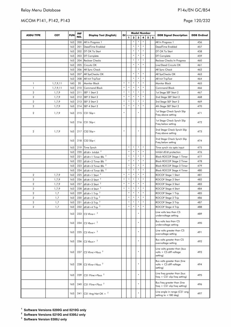
Relay Menu Database
MiCOM P141, P142, P143
P14x/EN GC/B54
Page 120/232
1 2 3 4 5 6
163 200 AR In Progress 1 * * * AR In Progress 1 456
163 201 DeadTime Enabled * * * DeadTime Enabled 457
163 202 DT OK To Start * * * DT OK To Start 458
163 203 DT Complete * * * DT Complete 459
163 204 Reclose Checks * * * Reclose Checks In Progress 460
163 205 Circuits OK * * * Live/Dead Circuits OK 461
163 206 AR Sync Check * AR Sync Check 462
163 207 AR SysChecks OK * * * AR SysChecks OK 463
163 208 AR Init TripTest * * * AR Init TripTest 464
1 1,7,9,11 160 20 Monitor Block * * * * * Monitor Block 465
1 1,7,9,11 163 210 Command Block * * * * * Command Block 466
2 1,7,9 163 211 SEF 1 Start 2 * * * * * 1st Stage SEF Start 2 467
2 1,7,9 163 212 SEF 2 Start 2 * * * * * 2nd Stage SEF Start 2 468
2 1,7,9 163 213 SEF 3 Start 2 * * * * * 3rd Stage SEF Start 2 469
2 1,7,9 163 214 SEF 4 Start 2 * * * * * 4th Stage SEF Start 2 470
2 1,7,9 163 215 CS1 Slip> * *1st Stage Check Synch Slip Freq above setting
471
163 216 CS1 Slip<1st Stage Check Synch Slip Freq below setting
472
2 1,7,9 163 217 CS2 Slip> * *2nd Stage Check Synch Slip Freq above setting
473
163 218 CS2 Slip<2nd Stage Check Synch Slip Freq below setting
474
163 219 Time Synch * * * * Time synch via opto input 475
163 220 df/dt> Inhibit 2 * * * * Inhibit df/dt protection 476
163 221 df/dt>1 Timer Blk 2 * * * * Block ROCOF Stage 1 Timer 477
163 222 df/dt>2 Timer Blk 2 * * * * Block ROCOF Stage 2 Timer 478
163 223 df/dt>3 Timer Blk 2 * * * * Block ROCOF Stage 3 Timer 479
163 224 df/dt>4 Timer Blk 2 * * * * Block ROCOF Stage 4 Timer 480
2 1,7,9 163 225 df/dt>1 Start 2 * * * * * ROCOF Stage 1 Start 481
2 1,7,9 163 226 df/dt>2 Start 2 * * * * * ROCOF Stage 2 Start 482
2 1,7,9 163 227 df/dt>3 Start 2 * * * * * ROCOF Stage 3 Start 483
2 1,7,9 163 228 df/dt>4 Start 2 * * * * * ROCOF Stage 4 Start 484
2 1,7 163 229 df/dt>1 Trip 2 * * * * ROCOF Stage 1 Trip 485
2 1,7 163 230 df/dt>2 Trip 2 * * * * ROCOF Stage 2 Trip 486
2 1,7 163 231 df/dt>3 Trip 2 * * * * ROCOF Stage 3 Trip 487
2 1,7 163 232 df/dt>4 Trip 2 * * * * ROCOF Stage 4 Trip 488
163 233 CS Vline< 2 *Line volts less than CS undervoltage setting
489
163 234 CS Vbus< 2 *Bus volts less than CS undervoltage setting
490
163 235 CS Vline> 2 *Line volts greater than CS overvoltage setting
491
163 236 CS Vbus> 2 *Bus volts greater than CS overvoltage setting
492
163 237 CS Vline>Vbus 2 *Line volts greater than (bus volts + CS diff voltage setting)
493
163 238 CS Vline<Vbus 2 *Bus volts greater than (line volts + CS diff voltage setting)
494
163 239 CS1 Fline>Fbus 2 *Line freq greater than (bus freq + CS1 slip freq setting)
495
163 240 CS1 Fline<Fbus 2 *Bus freq greater than (line freq + CS1 slip freq setting)
496
163 241 CS1 Ang Not OK + 2 *Line angle in range (CS1 ang setting to +180 deg)
497
ASDU TYPE COT FUNINF NO.
Display Text (English) GIModel Number
DDB Signal Description DDB Ordinal
1 Software Versions 0200G and 0210G only2 Software Versions 0210G and 0300J only3 Software Version 0300J only
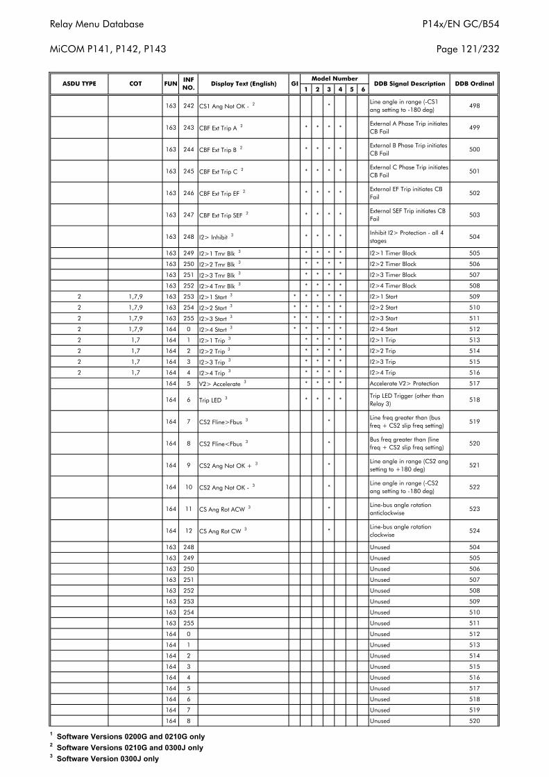
Relay Menu Database
MiCOM P141, P142, P143
P14x/EN GC/B54
Page 121/232
1 2 3 4 5 6
163 242 CS1 Ang Not OK - 2 *Line angle in range (-CS1 ang setting to -180 deg)
498
163 243 CBF Ext Trip A 2 * * * *External A Phase Trip initiates CB Fail
499
163 244 CBF Ext Trip B 2 * * * *External B Phase Trip initiates CB Fail
500
163 245 CBF Ext Trip C 2 * * * *External C Phase Trip initiates CB Fail
501
163 246 CBF Ext Trip EF 2 * * * *External EF Trip initiates CB Fail
502
163 247 CBF Ext Trip SEF 2 * * * *External SEF Trip initiates CB Fail
503
163 248 I2> Inhibit 3 * * * *Inhibit I2> Protection - all 4 stages
504
163 249 I2>1 Tmr Blk 3 * * * * I2>1 Timer Block 505
163 250 I2>2 Tmr Blk 3 * * * * I2>2 Timer Block 506
163 251 I2>3 Tmr Blk 3 * * * * I2>3 Timer Block 507
163 252 I2>4 Tmr Blk 3 * * * * I2>4 Timer Block 508
2 1,7,9 163 253 I2>1 Start 3 * * * * * I2>1 Start 509
2 1,7,9 163 254 I2>2 Start 3 * * * * * I2>2 Start 510
2 1,7,9 163 255 I2>3 Start 3 * * * * * I2>3 Start 511
2 1,7,9 164 0 I2>4 Start 3 * * * * * I2>4 Start 512
2 1,7 164 1 I2>1 Trip 3 * * * * I2>1 Trip 513
2 1,7 164 2 I2>2 Trip 3 * * * * I2>2 Trip 514
2 1,7 164 3 I2>3 Trip 3 * * * * I2>3 Trip 515
2 1,7 164 4 I2>4 Trip 3 * * * * I2>4 Trip 516
164 5 V2> Accelerate 3 * * * * Accelerate V2> Protection 517
164 6 Trip LED 3 * * * *Trip LED Trigger (other than Relay 3)
518
164 7 CS2 Fline>Fbus 3 *Line freq greater than (bus freq + CS2 slip freq setting)
519
164 8 CS2 Fline<Fbus 3 *Bus freq greater than (line freq + CS2 slip freq setting)
520
164 9 CS2 Ang Not OK + 3 *Line angle in range (CS2 ang setting to +180 deg)
521
164 10 CS2 Ang Not OK - 3 *Line angle in range (-CS2 ang setting to -180 deg)
522
164 11 CS Ang Rot ACW 3 *Line-bus angle rotation anticlockwise
523
164 12 CS Ang Rot CW 3 *Line-bus angle rotation clockwise
524
163 248 Unused 504
163 249 Unused 505
163 250 Unused 506
163 251 Unused 507
163 252 Unused 508
163 253 Unused 509
163 254 Unused 510
163 255 Unused 511
164 0 Unused 512
164 1 Unused 513
164 2 Unused 514
164 3 Unused 515
164 4 Unused 516
164 5 Unused 517
164 6 Unused 518
164 7 Unused 519
164 8 Unused 520
DDB OrdinalGIModel Number
DDB Signal DescriptionASDU TYPE COT FUNINF NO.
Display Text (English)
1 Software Versions 0200G and 0210G only2 Software Versions 0210G and 0300J only3 Software Version 0300J only

Relay Menu Database
MiCOM P141, P142, P143
P14x/EN GC/B54
Page 122/232
1 2 3 4 5 6
164 9 Unused 521
164 10 Unused 522
164 11 Unused 523
164 12 Unused 524
164 13 Unused 525
164 14 Unused 526
164 15 Unused 527
164 16 Unused 528
164 17 Unused 529
164 18 Unused 530
164 19 Unused 531
164 20 Unused 532
164 21 Unused 533
164 22 Unused 534
164 23 Unused 535
164 24 Unused 536
164 25 Unused 537
164 26 Unused 538
164 27 Unused 539
164 28 Unused 540
164 29 Unused 541
164 30 Unused 542
164 31 Unused 543
164 32 Unused 544
164 33 Unused 545
164 34 Unused 546
164 35 Unused 547
164 36 Unused 548
164 37 Unused 549
164 38 Unused 550
164 39 Unused 551
164 40 Unused 552
164 41 Unused 553
164 42 Unused 554
164 43 Unused 555
164 44 Unused 556
164 45 Unused 557
164 46 Unused 558
164 47 Unused 559
164 48 Unused 560
164 49 Unused 561
164 50 Unused 562
164 51 Unused 563
164 52 Unused 564
164 53 Unused 565
164 54 Unused 566
164 55 Unused 567
164 56 Unused 568
164 57 Unused 569
164 58 Unused 570
164 59 Unused 571
164 60 Unused 572
164 61 Unused 573
164 62 Unused 574
164 63 Unused 575
164 64 Unused 576
164 65 Unused 577
164 66 Unused 578
ASDU TYPE COT FUNINF NO.
Display Text (English) GIModel Number
DDB Signal Description DDB Ordinal
1 Software Versions 0200G and 0210G only2 Software Versions 0210G and 0300J only3 Software Version 0300J only
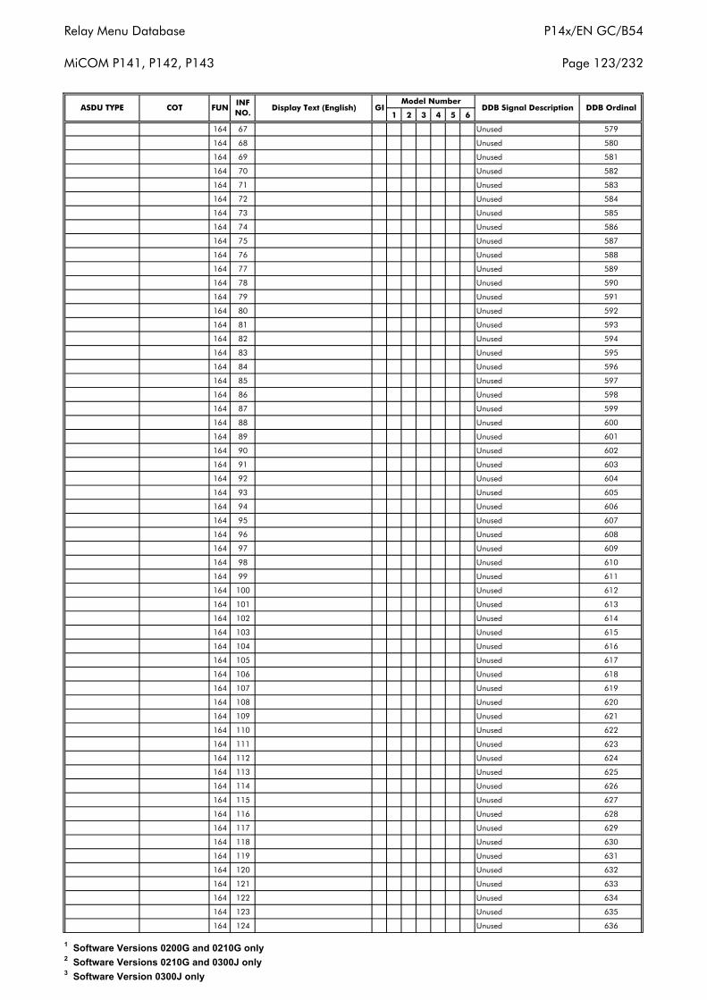
Relay Menu Database
MiCOM P141, P142, P143
P14x/EN GC/B54
Page 123/232
1 2 3 4 5 6
164 67 Unused 579
164 68 Unused 580
164 69 Unused 581
164 70 Unused 582
164 71 Unused 583
164 72 Unused 584
164 73 Unused 585
164 74 Unused 586
164 75 Unused 587
164 76 Unused 588
164 77 Unused 589
164 78 Unused 590
164 79 Unused 591
164 80 Unused 592
164 81 Unused 593
164 82 Unused 594
164 83 Unused 595
164 84 Unused 596
164 85 Unused 597
164 86 Unused 598
164 87 Unused 599
164 88 Unused 600
164 89 Unused 601
164 90 Unused 602
164 91 Unused 603
164 92 Unused 604
164 93 Unused 605
164 94 Unused 606
164 95 Unused 607
164 96 Unused 608
164 97 Unused 609
164 98 Unused 610
164 99 Unused 611
164 100 Unused 612
164 101 Unused 613
164 102 Unused 614
164 103 Unused 615
164 104 Unused 616
164 105 Unused 617
164 106 Unused 618
164 107 Unused 619
164 108 Unused 620
164 109 Unused 621
164 110 Unused 622
164 111 Unused 623
164 112 Unused 624
164 113 Unused 625
164 114 Unused 626
164 115 Unused 627
164 116 Unused 628
164 117 Unused 629
164 118 Unused 630
164 119 Unused 631
164 120 Unused 632
164 121 Unused 633
164 122 Unused 634
164 123 Unused 635
164 124 Unused 636
DDB Signal Description DDB OrdinalASDU TYPE COT FUNINF NO.
Display Text (English) GIModel Number
1 Software Versions 0200G and 0210G only2 Software Versions 0210G and 0300J only3 Software Version 0300J only

Relay Menu Database
MiCOM P141, P142, P143
P14x/EN GC/B54
Page 124/232
1 2 3 4 5 6
164 125 Unused 637
164 126 Unused 638
164 127 Unused 639
164 128 Unused 640
164 129 Unused 641
164 130 Unused 642
164 131 Unused 643
164 132 Unused 644
164 133 Unused 645
164 134 Unused 646
164 135 Unused 647
164 136 Unused 648
164 137 Unused 649
164 138 Unused 650
164 139 Unused 651
164 140 Unused 652
164 141 Unused 653
164 142 Unused 654
164 143 Unused 655
164 144 Unused 656
164 145 Unused 657
164 146 Unused 658
164 147 Unused 659
164 148 Unused 660
164 149 Unused 661
164 150 Unused 662
164 151 Unused 663
164 152 Unused 664
164 153 Unused 665
164 154 Unused 666
164 155 Unused 667
164 156 Unused 668
164 157 Unused 669
164 158 Unused 670
164 159 Unused 671
164 160 Unused 672
164 161 Unused 673
164 162 Unused 674
164 163 Unused 675
164 164 Unused 676
164 165 Unused 677
164 166 Unused 678
164 167 Unused 679
164 168 Unused 680
164 169 Unused 681
164 170 Unused 682
164 171 Unused 683
164 172 Unused 684
164 173 Unused 685
164 174 Unused 686
164 175 Unused 687
164 176 Unused 688
164 177 Unused 689
164 178 Unused 690
164 179 Unused 691
164 180 Unused 692
164 181 Unused 693
164 182 Unused 694
DDB OrdinalDisplay Text (English) GIModel Number
DDB Signal DescriptionASDU TYPE COT FUNINF NO.
1 Software Versions 0200G and 0210G only2 Software Versions 0210G and 0300J only3 Software Version 0300J only

Relay Menu Database
MiCOM P141, P142, P143
P14x/EN GC/B54
Page 125/232
1 2 3 4 5 6
164 183 Unused 695
164 184 Unused 696
164 185 Unused 697
164 186 Unused 698
164 187 Unused 699
164 188 Unused 700
164 189 Unused 701
164 190 Unused 702
164 191 Unused 703
164 192 Unused 704
164 193 Unused 705
164 194 Unused 706
164 195 Unused 707
164 196 Unused 708
164 197 Unused 709
164 198 Unused 710
164 199 Unused 711
164 200 Unused 712
164 201 Unused 713
164 202 Unused 714
164 203 Unused 715
164 204 Unused 716
164 205 Unused 717
164 206 Unused 718
164 207 Unused 719
164 208 Unused 720
164 209 Unused 721
164 210 Unused 722
164 211 Unused 723
164 212 Unused 724
164 213 Unused 725
164 214 Unused 726
164 215 Unused 727
164 216 Unused 728
164 217 Unused 729
164 218 Unused 730
164 219 Unused 731
164 220 Unused 732
164 221 Unused 733
164 222 Unused 734
164 223 Unused 735
164 224 Unused 736
164 225 Unused 737
164 226 Unused 738
164 227 Unused 739
164 228 Unused 740
164 229 Unused 741
164 230 Unused 742
164 231 Unused 743
164 232 Unused 744
164 233 Unused 745
164 234 Unused 746
164 235 Unused 747
164 236 Unused 748
164 237 Unused 749
164 238 Unused 750
164 239 Unused 751
164 240 Unused 752
GI DDB Signal Description DDB OrdinalASDU TYPE COT FUNModel NumberINF
NO.Display Text (English)
1 Software Versions 0200G and 0210G only2 Software Versions 0210G and 0300J only3 Software Version 0300J only
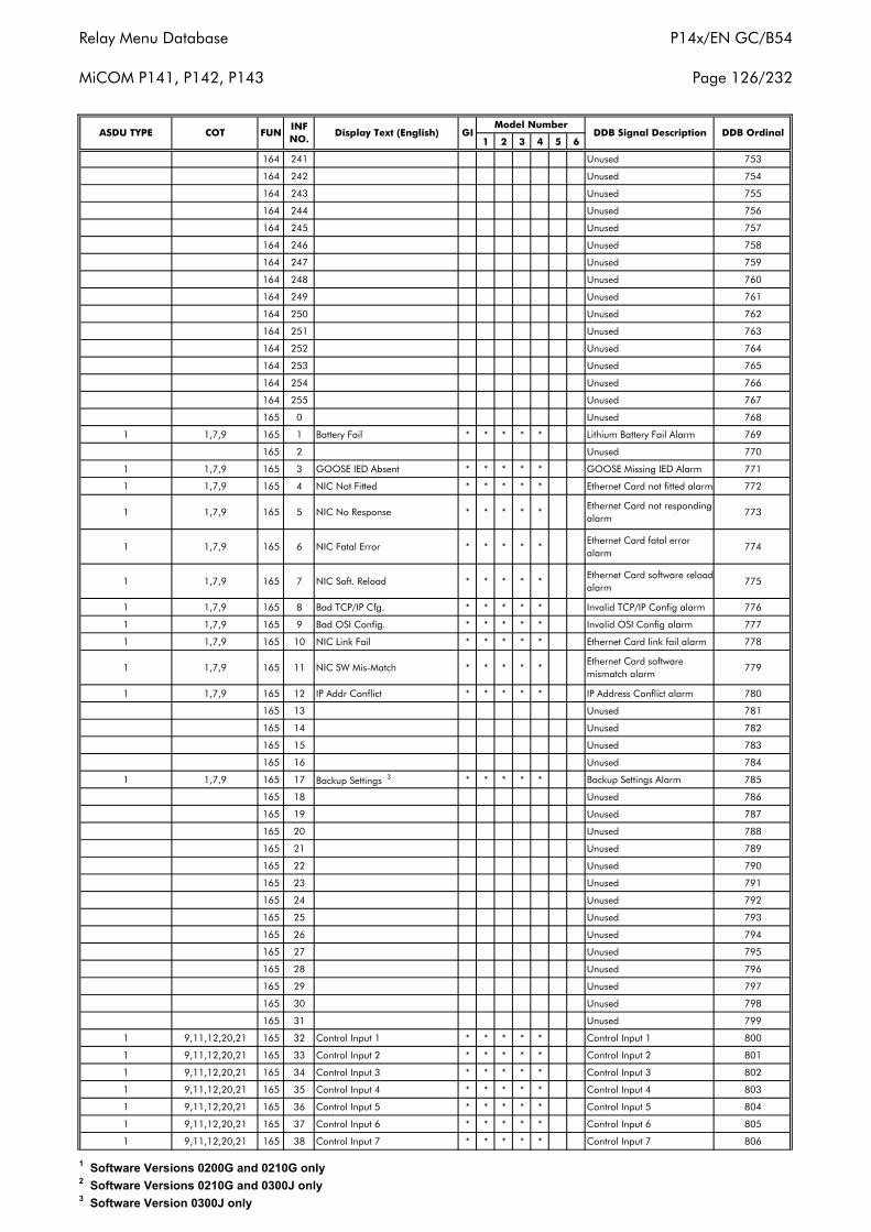
Relay Menu Database
MiCOM P141, P142, P143
P14x/EN GC/B54
Page 126/232
1 2 3 4 5 6
164 241 Unused 753
164 242 Unused 754
164 243 Unused 755
164 244 Unused 756
164 245 Unused 757
164 246 Unused 758
164 247 Unused 759
164 248 Unused 760
164 249 Unused 761
164 250 Unused 762
164 251 Unused 763
164 252 Unused 764
164 253 Unused 765
164 254 Unused 766
164 255 Unused 767
165 0 Unused 768
1 1,7,9 165 1 Battery Fail * * * * * Lithium Battery Fail Alarm 769
165 2 Unused 770
1 1,7,9 165 3 GOOSE IED Absent * * * * * GOOSE Missing IED Alarm 771
1 1,7,9 165 4 NIC Not Fitted * * * * * Ethernet Card not fitted alarm 772
1 1,7,9 165 5 NIC No Response * * * * *Ethernet Card not responding alarm
773
1 1,7,9 165 6 NIC Fatal Error * * * * *Ethernet Card fatal error alarm
774
1 1,7,9 165 7 NIC Soft. Reload * * * * *Ethernet Card software reloadalarm
775
1 1,7,9 165 8 Bad TCP/IP Cfg. * * * * * Invalid TCP/IP Config alarm 776
1 1,7,9 165 9 Bad OSI Config. * * * * * Invalid OSI Config alarm 777
1 1,7,9 165 10 NIC Link Fail * * * * * Ethernet Card link fail alarm 778
1 1,7,9 165 11 NIC SW Mis-Match * * * * *Ethernet Card software mismatch alarm
779
1 1,7,9 165 12 IP Addr Conflict * * * * * IP Address Conflict alarm 780
165 13 Unused 781
165 14 Unused 782
165 15 Unused 783
165 16 Unused 784
1 1,7,9 165 17 Backup Settings 3 * * * * * Backup Settings Alarm 785
165 18 Unused 786
165 19 Unused 787
165 20 Unused 788
165 21 Unused 789
165 22 Unused 790
165 23 Unused 791
165 24 Unused 792
165 25 Unused 793
165 26 Unused 794
165 27 Unused 795
165 28 Unused 796
165 29 Unused 797
165 30 Unused 798
165 31 Unused 799
1 9,11,12,20,21 165 32 Control Input 1 * * * * * Control Input 1 800
1 9,11,12,20,21 165 33 Control Input 2 * * * * * Control Input 2 801
1 9,11,12,20,21 165 34 Control Input 3 * * * * * Control Input 3 802
1 9,11,12,20,21 165 35 Control Input 4 * * * * * Control Input 4 803
1 9,11,12,20,21 165 36 Control Input 5 * * * * * Control Input 5 804
1 9,11,12,20,21 165 37 Control Input 6 * * * * * Control Input 6 805
1 9,11,12,20,21 165 38 Control Input 7 * * * * * Control Input 7 806
INF NO.
Display Text (English) DDB Signal Description DDB OrdinalGIModel Number
ASDU TYPE COT FUN
1 Software Versions 0200G and 0210G only2 Software Versions 0210G and 0300J only3 Software Version 0300J only
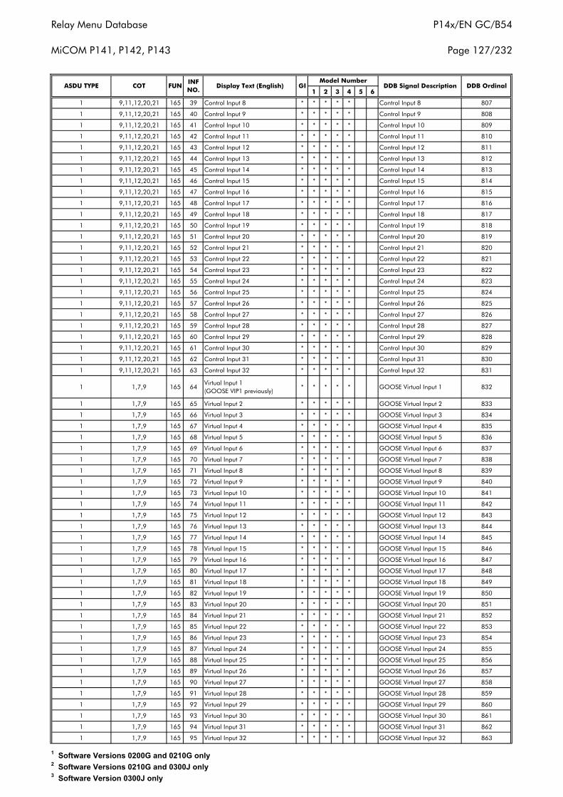
Relay Menu Database
MiCOM P141, P142, P143
P14x/EN GC/B54
Page 127/232
1 2 3 4 5 6
1 9,11,12,20,21 165 39 Control Input 8 * * * * * Control Input 8 807
1 9,11,12,20,21 165 40 Control Input 9 * * * * * Control Input 9 808
1 9,11,12,20,21 165 41 Control Input 10 * * * * * Control Input 10 809
1 9,11,12,20,21 165 42 Control Input 11 * * * * * Control Input 11 810
1 9,11,12,20,21 165 43 Control Input 12 * * * * * Control Input 12 811
1 9,11,12,20,21 165 44 Control Input 13 * * * * * Control Input 13 812
1 9,11,12,20,21 165 45 Control Input 14 * * * * * Control Input 14 813
1 9,11,12,20,21 165 46 Control Input 15 * * * * * Control Input 15 814
1 9,11,12,20,21 165 47 Control Input 16 * * * * * Control Input 16 815
1 9,11,12,20,21 165 48 Control Input 17 * * * * * Control Input 17 816
1 9,11,12,20,21 165 49 Control Input 18 * * * * * Control Input 18 817
1 9,11,12,20,21 165 50 Control Input 19 * * * * * Control Input 19 818
1 9,11,12,20,21 165 51 Control Input 20 * * * * * Control Input 20 819
1 9,11,12,20,21 165 52 Control Input 21 * * * * * Control Input 21 820
1 9,11,12,20,21 165 53 Control Input 22 * * * * * Control Input 22 821
1 9,11,12,20,21 165 54 Control Input 23 * * * * * Control Input 23 822
1 9,11,12,20,21 165 55 Control Input 24 * * * * * Control Input 24 823
1 9,11,12,20,21 165 56 Control Input 25 * * * * * Control Input 25 824
1 9,11,12,20,21 165 57 Control Input 26 * * * * * Control Input 26 825
1 9,11,12,20,21 165 58 Control Input 27 * * * * * Control Input 27 826
1 9,11,12,20,21 165 59 Control Input 28 * * * * * Control Input 28 827
1 9,11,12,20,21 165 60 Control Input 29 * * * * * Control Input 29 828
1 9,11,12,20,21 165 61 Control Input 30 * * * * * Control Input 30 829
1 9,11,12,20,21 165 62 Control Input 31 * * * * * Control Input 31 830
1 9,11,12,20,21 165 63 Control Input 32 * * * * * Control Input 32 831
1 1,7,9 165 64Virtual Input 1 (GOOSE VIP1 previously)
* * * * * GOOSE Virtual Input 1 832
1 1,7,9 165 65 Virtual Input 2 * * * * * GOOSE Virtual Input 2 833
1 1,7,9 165 66 Virtual Input 3 * * * * * GOOSE Virtual Input 3 834
1 1,7,9 165 67 Virtual Input 4 * * * * * GOOSE Virtual Input 4 835
1 1,7,9 165 68 Virtual Input 5 * * * * * GOOSE Virtual Input 5 836
1 1,7,9 165 69 Virtual Input 6 * * * * * GOOSE Virtual Input 6 837
1 1,7,9 165 70 Virtual Input 7 * * * * * GOOSE Virtual Input 7 838
1 1,7,9 165 71 Virtual Input 8 * * * * * GOOSE Virtual Input 8 839
1 1,7,9 165 72 Virtual Input 9 * * * * * GOOSE Virtual Input 9 840
1 1,7,9 165 73 Virtual Input 10 * * * * * GOOSE Virtual Input 10 841
1 1,7,9 165 74 Virtual Input 11 * * * * * GOOSE Virtual Input 11 842
1 1,7,9 165 75 Virtual Input 12 * * * * * GOOSE Virtual Input 12 843
1 1,7,9 165 76 Virtual Input 13 * * * * * GOOSE Virtual Input 13 844
1 1,7,9 165 77 Virtual Input 14 * * * * * GOOSE Virtual Input 14 845
1 1,7,9 165 78 Virtual Input 15 * * * * * GOOSE Virtual Input 15 846
1 1,7,9 165 79 Virtual Input 16 * * * * * GOOSE Virtual Input 16 847
1 1,7,9 165 80 Virtual Input 17 * * * * * GOOSE Virtual Input 17 848
1 1,7,9 165 81 Virtual Input 18 * * * * * GOOSE Virtual Input 18 849
1 1,7,9 165 82 Virtual Input 19 * * * * * GOOSE Virtual Input 19 850
1 1,7,9 165 83 Virtual Input 20 * * * * * GOOSE Virtual Input 20 851
1 1,7,9 165 84 Virtual Input 21 * * * * * GOOSE Virtual Input 21 852
1 1,7,9 165 85 Virtual Input 22 * * * * * GOOSE Virtual Input 22 853
1 1,7,9 165 86 Virtual Input 23 * * * * * GOOSE Virtual Input 23 854
1 1,7,9 165 87 Virtual Input 24 * * * * * GOOSE Virtual Input 24 855
1 1,7,9 165 88 Virtual Input 25 * * * * * GOOSE Virtual Input 25 856
1 1,7,9 165 89 Virtual Input 26 * * * * * GOOSE Virtual Input 26 857
1 1,7,9 165 90 Virtual Input 27 * * * * * GOOSE Virtual Input 27 858
1 1,7,9 165 91 Virtual Input 28 * * * * * GOOSE Virtual Input 28 859
1 1,7,9 165 92 Virtual Input 29 * * * * * GOOSE Virtual Input 29 860
1 1,7,9 165 93 Virtual Input 30 * * * * * GOOSE Virtual Input 30 861
1 1,7,9 165 94 Virtual Input 31 * * * * * GOOSE Virtual Input 31 862
1 1,7,9 165 95 Virtual Input 32 * * * * * GOOSE Virtual Input 32 863
DDB OrdinalModel Number
DDB Signal DescriptionASDU TYPE COT FUNINF NO.
Display Text (English) GI
1 Software Versions 0200G and 0210G only2 Software Versions 0210G and 0300J only3 Software Version 0300J only
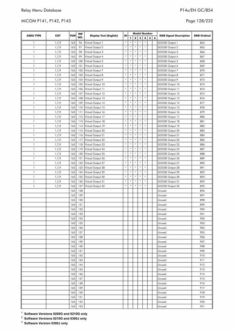
Relay Menu Database
MiCOM P141, P142, P143
P14x/EN GC/B54
Page 128/232
1 2 3 4 5 6
1 1,7,9 165 96 Virtual Output 1 * * * * * GOOSE Output 1 864
1 1,7,9 165 97 Virtual Output 2 * * * * * GOOSE Output 2 865
1 1,7,9 165 98 Virtual Output 3 * * * * * GOOSE Output 3 866
1 1,7,9 165 99 Virtual Output 4 * * * * * GOOSE Output 4 867
1 1,7,9 165 100 Virtual Output 5 * * * * * GOOSE Output 5 868
1 1,7,9 165 101 Virtual Output 6 * * * * * GOOSE Output 6 869
1 1,7,9 165 102 Virtual Output 7 * * * * * GOOSE Output 7 870
1 1,7,9 165 103 Virtual Output 8 * * * * * GOOSE Output 8 871
1 1,7,9 165 104 Virtual Output 9 * * * * * GOOSE Output 9 872
1 1,7,9 165 105 Virtual Output 10 * * * * * GOOSE Output 10 873
1 1,7,9 165 106 Virtual Output 11 * * * * * GOOSE Output 11 874
1 1,7,9 165 107 Virtual Output 12 * * * * * GOOSE Output 12 875
1 1,7,9 165 108 Virtual Output 13 * * * * * GOOSE Output 13 876
1 1,7,9 165 109 Virtual Output 14 * * * * * GOOSE Output 14 877
1 1,7,9 165 110 Virtual Output 15 * * * * * GOOSE Output 15 878
1 1,7,9 165 111 Virtual Output 16 * * * * * GOOSE Output 16 879
1 1,7,9 165 112 Virtual Output 17 * * * * * GOOSE Output 17 880
1 1,7,9 165 113 Virtual Output 18 * * * * * GOOSE Output 18 881
1 1,7,9 165 114 Virtual Output 19 * * * * * GOOSE Output 19 882
1 1,7,9 165 115 Virtual Output 20 * * * * * GOOSE Output 20 883
1 1,7,9 165 116 Virtual Output 21 * * * * * GOOSE Output 21 884
1 1,7,9 165 117 Virtual Output 22 * * * * * GOOSE Output 22 885
1 1,7,9 165 118 Virtual Output 23 * * * * * GOOSE Output 23 886
1 1,7,9 165 119 Virtual Output 24 * * * * * GOOSE Output 24 887
1 1,7,9 165 120 Virtual Output 25 * * * * * GOOSE Output 25 888
1 1,7,9 165 121 Virtual Output 26 * * * * * GOOSE Output 26 889
1 1,7,9 165 122 Virtual Output 27 * * * * * GOOSE Output 27 890
1 1,7,9 165 123 Virtual Output 28 * * * * * GOOSE Output 28 891
1 1,7,9 165 124 Virtual Output 29 * * * * * GOOSE Output 29 892
1 1,7,9 165 125 Virtual Output 30 * * * * * GOOSE Output 30 893
1 1,7,9 165 126 Virtual Output 31 * * * * * GOOSE Output 31 894
1 1,7,9 165 127 Virtual Output 32 * * * * * GOOSE Output 32 895
165 128 Unused 896
165 129 Unused 897
165 130 Unused 898
165 131 Unused 899
165 132 Unused 900
165 133 Unused 901
165 134 Unused 902
165 135 Unused 903
165 136 Unused 904
165 137 Unused 905
165 138 Unused 906
165 139 Unused 907
165 140 Unused 908
165 141 Unused 909
165 142 Unused 910
165 143 Unused 911
165 144 Unused 912
165 145 Unused 913
165 146 Unused 914
165 147 Unused 915
165 148 Unused 916
165 149 Unused 917
165 150 Unused 918
165 151 Unused 919
165 152 Unused 920
165 153 Unused 921
ASDU TYPE COT FUNINF NO.
Display Text (English) GIModel Number
DDB Signal Description DDB Ordinal
1 Software Versions 0200G and 0210G only2 Software Versions 0210G and 0300J only3 Software Version 0300J only
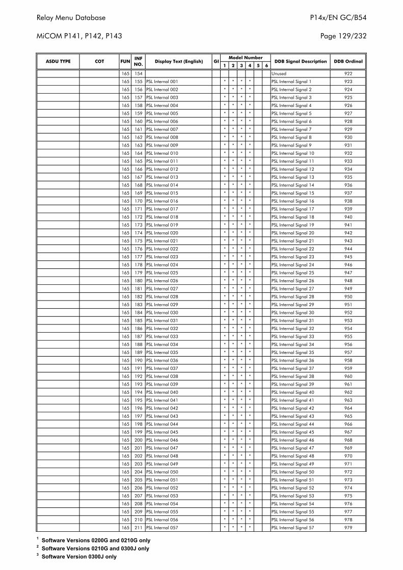
Relay Menu Database
MiCOM P141, P142, P143
P14x/EN GC/B54
Page 129/232
1 2 3 4 5 6
165 154 Unused 922
165 155 PSL Internal 001 * * * * PSL Internal Signal 1 923
165 156 PSL Internal 002 * * * * PSL Internal Signal 2 924
165 157 PSL Internal 003 * * * * PSL Internal Signal 3 925
165 158 PSL Internal 004 * * * * PSL Internal Signal 4 926
165 159 PSL Internal 005 * * * * PSL Internal Signal 5 927
165 160 PSL Internal 006 * * * * PSL Internal Signal 6 928
165 161 PSL Internal 007 * * * * PSL Internal Signal 7 929
165 162 PSL Internal 008 * * * * PSL Internal Signal 8 930
165 163 PSL Internal 009 * * * * PSL Internal Signal 9 931
165 164 PSL Internal 010 * * * * PSL Internal Signal 10 932
165 165 PSL Internal 011 * * * * PSL Internal Signal 11 933
165 166 PSL Internal 012 * * * * PSL Internal Signal 12 934
165 167 PSL Internal 013 * * * * PSL Internal Signal 13 935
165 168 PSL Internal 014 * * * * PSL Internal Signal 14 936
165 169 PSL Internal 015 * * * * PSL Internal Signal 15 937
165 170 PSL Internal 016 * * * * PSL Internal Signal 16 938
165 171 PSL Internal 017 * * * * PSL Internal Signal 17 939
165 172 PSL Internal 018 * * * * PSL Internal Signal 18 940
165 173 PSL Internal 019 * * * * PSL Internal Signal 19 941
165 174 PSL Internal 020 * * * * PSL Internal Signal 20 942
165 175 PSL Internal 021 * * * * PSL Internal Signal 21 943
165 176 PSL Internal 022 * * * * PSL Internal Signal 22 944
165 177 PSL Internal 023 * * * * PSL Internal Signal 23 945
165 178 PSL Internal 024 * * * * PSL Internal Signal 24 946
165 179 PSL Internal 025 * * * * PSL Internal Signal 25 947
165 180 PSL Internal 026 * * * * PSL Internal Signal 26 948
165 181 PSL Internal 027 * * * * PSL Internal Signal 27 949
165 182 PSL Internal 028 * * * * PSL Internal Signal 28 950
165 183 PSL Internal 029 * * * * PSL Internal Signal 29 951
165 184 PSL Internal 030 * * * * PSL Internal Signal 30 952
165 185 PSL Internal 031 * * * * PSL Internal Signal 31 953
165 186 PSL Internal 032 * * * * PSL Internal Signal 32 954
165 187 PSL Internal 033 * * * * PSL Internal Signal 33 955
165 188 PSL Internal 034 * * * * PSL Internal Signal 34 956
165 189 PSL Internal 035 * * * * PSL Internal Signal 35 957
165 190 PSL Internal 036 * * * * PSL Internal Signal 36 958
165 191 PSL Internal 037 * * * * PSL Internal Signal 37 959
165 192 PSL Internal 038 * * * * PSL Internal Signal 38 960
165 193 PSL Internal 039 * * * * PSL Internal Signal 39 961
165 194 PSL Internal 040 * * * * PSL Internal Signal 40 962
165 195 PSL Internal 041 * * * * PSL Internal Signal 41 963
165 196 PSL Internal 042 * * * * PSL Internal Signal 42 964
165 197 PSL Internal 043 * * * * PSL Internal Signal 43 965
165 198 PSL Internal 044 * * * * PSL Internal Signal 44 966
165 199 PSL Internal 045 * * * * PSL Internal Signal 45 967
165 200 PSL Internal 046 * * * * PSL Internal Signal 46 968
165 201 PSL Internal 047 * * * * PSL Internal Signal 47 969
165 202 PSL Internal 048 * * * * PSL Internal Signal 48 970
165 203 PSL Internal 049 * * * * PSL Internal Signal 49 971
165 204 PSL Internal 050 * * * * PSL Internal Signal 50 972
165 205 PSL Internal 051 * * * * PSL Internal Signal 51 973
165 206 PSL Internal 052 * * * * PSL Internal Signal 52 974
165 207 PSL Internal 053 * * * * PSL Internal Signal 53 975
165 208 PSL Internal 054 * * * * PSL Internal Signal 54 976
165 209 PSL Internal 055 * * * * PSL Internal Signal 55 977
165 210 PSL Internal 056 * * * * PSL Internal Signal 56 978
165 211 PSL Internal 057 * * * * PSL Internal Signal 57 979
Model NumberDDB Signal DescriptionASDU TYPE COT FUN
INF NO.
GI DDB OrdinalDisplay Text (English)
1 Software Versions 0200G and 0210G only2 Software Versions 0210G and 0300J only3 Software Version 0300J only
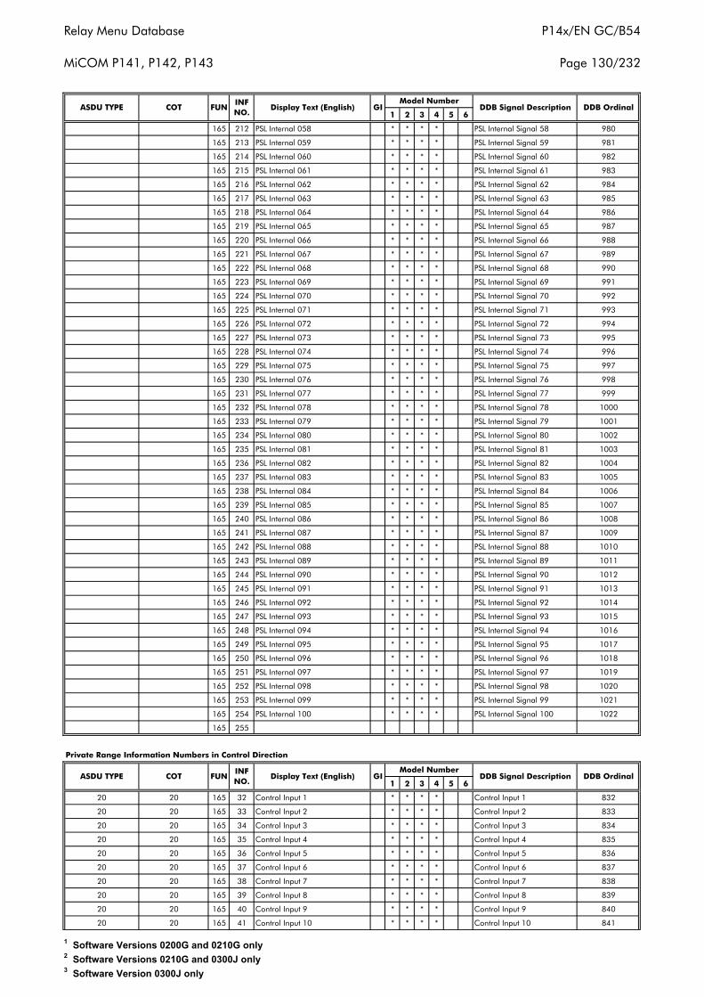
Relay Menu Database
MiCOM P141, P142, P143
P14x/EN GC/B54
Page 130/232
1 2 3 4 5 6
165 212 PSL Internal 058 * * * * PSL Internal Signal 58 980
165 213 PSL Internal 059 * * * * PSL Internal Signal 59 981
165 214 PSL Internal 060 * * * * PSL Internal Signal 60 982
165 215 PSL Internal 061 * * * * PSL Internal Signal 61 983
165 216 PSL Internal 062 * * * * PSL Internal Signal 62 984
165 217 PSL Internal 063 * * * * PSL Internal Signal 63 985
165 218 PSL Internal 064 * * * * PSL Internal Signal 64 986
165 219 PSL Internal 065 * * * * PSL Internal Signal 65 987
165 220 PSL Internal 066 * * * * PSL Internal Signal 66 988
165 221 PSL Internal 067 * * * * PSL Internal Signal 67 989
165 222 PSL Internal 068 * * * * PSL Internal Signal 68 990
165 223 PSL Internal 069 * * * * PSL Internal Signal 69 991
165 224 PSL Internal 070 * * * * PSL Internal Signal 70 992
165 225 PSL Internal 071 * * * * PSL Internal Signal 71 993
165 226 PSL Internal 072 * * * * PSL Internal Signal 72 994
165 227 PSL Internal 073 * * * * PSL Internal Signal 73 995
165 228 PSL Internal 074 * * * * PSL Internal Signal 74 996
165 229 PSL Internal 075 * * * * PSL Internal Signal 75 997
165 230 PSL Internal 076 * * * * PSL Internal Signal 76 998
165 231 PSL Internal 077 * * * * PSL Internal Signal 77 999
165 232 PSL Internal 078 * * * * PSL Internal Signal 78 1000
165 233 PSL Internal 079 * * * * PSL Internal Signal 79 1001
165 234 PSL Internal 080 * * * * PSL Internal Signal 80 1002
165 235 PSL Internal 081 * * * * PSL Internal Signal 81 1003
165 236 PSL Internal 082 * * * * PSL Internal Signal 82 1004
165 237 PSL Internal 083 * * * * PSL Internal Signal 83 1005
165 238 PSL Internal 084 * * * * PSL Internal Signal 84 1006
165 239 PSL Internal 085 * * * * PSL Internal Signal 85 1007
165 240 PSL Internal 086 * * * * PSL Internal Signal 86 1008
165 241 PSL Internal 087 * * * * PSL Internal Signal 87 1009
165 242 PSL Internal 088 * * * * PSL Internal Signal 88 1010
165 243 PSL Internal 089 * * * * PSL Internal Signal 89 1011
165 244 PSL Internal 090 * * * * PSL Internal Signal 90 1012
165 245 PSL Internal 091 * * * * PSL Internal Signal 91 1013
165 246 PSL Internal 092 * * * * PSL Internal Signal 92 1014
165 247 PSL Internal 093 * * * * PSL Internal Signal 93 1015
165 248 PSL Internal 094 * * * * PSL Internal Signal 94 1016
165 249 PSL Internal 095 * * * * PSL Internal Signal 95 1017
165 250 PSL Internal 096 * * * * PSL Internal Signal 96 1018
165 251 PSL Internal 097 * * * * PSL Internal Signal 97 1019
165 252 PSL Internal 098 * * * * PSL Internal Signal 98 1020
165 253 PSL Internal 099 * * * * PSL Internal Signal 99 1021
165 254 PSL Internal 100 * * * * PSL Internal Signal 100 1022
165 255
1 2 3 4 5 6
20 20 165 32 Control Input 1 * * * * Control Input 1 832
20 20 165 33 Control Input 2 * * * * Control Input 2 833
20 20 165 34 Control Input 3 * * * * Control Input 3 834
20 20 165 35 Control Input 4 * * * * Control Input 4 835
20 20 165 36 Control Input 5 * * * * Control Input 5 836
20 20 165 37 Control Input 6 * * * * Control Input 6 837
20 20 165 38 Control Input 7 * * * * Control Input 7 838
20 20 165 39 Control Input 8 * * * * Control Input 8 839
20 20 165 40 Control Input 9 * * * * Control Input 9 840
20 20 165 41 Control Input 10 * * * * Control Input 10 841
GIModel Number
DDB Signal Description DDB Ordinal
Private Range Information Numbers in Control Direction
Model NumberDDB Signal Description DDB Ordinal
Display Text (English)
ASDU TYPE COT FUNINF NO.
Display Text (English) GI
ASDU TYPE COT FUNINF NO.
1 Software Versions 0200G and 0210G only2 Software Versions 0210G and 0300J only3 Software Version 0300J only
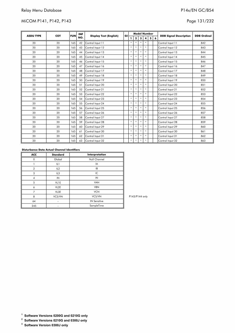
Relay Menu Database
MiCOM P141, P142, P143
P14x/EN GC/B54
Page 131/232
1 2 3 4 5 6
20 20 165 42 Control Input 11 * * * * Control Input 11 842
20 20 165 43 Control Input 12 * * * * Control Input 12 843
20 20 165 44 Control Input 13 * * * * Control Input 13 844
20 20 165 45 Control Input 14 * * * * Control Input 14 845
20 20 165 46 Control Input 15 * * * * Control Input 15 846
20 20 165 47 Control Input 16 * * * * Control Input 16 847
20 20 165 48 Control Input 17 * * * * Control Input 17 848
20 20 165 49 Control Input 18 * * * * Control Input 18 849
20 20 165 50 Control Input 19 * * * * Control Input 19 850
20 20 165 51 Control Input 20 * * * * Control Input 20 851
20 20 165 52 Control Input 21 * * * * Control Input 21 852
20 20 165 53 Control Input 22 * * * * Control Input 22 853
20 20 165 54 Control Input 23 * * * * Control Input 23 854
20 20 165 55 Control Input 24 * * * * Control Input 24 855
20 20 165 56 Control Input 25 * * * * Control Input 25 856
20 20 165 57 Control Input 26 * * * * Control Input 26 857
20 20 165 58 Control Input 27 * * * * Control Input 27 858
20 20 165 59 Control Input 28 * * * * Control Input 28 859
20 20 165 60 Control Input 29 * * * * Control Input 29 860
20 20 165 61 Control Input 30 * * * * Control Input 30 861
20 20 165 62 Control Input 31 * * * * Control Input 31 862
20 20 165 63 Control Input 32 * * * * Control Input 32 863
ACC Standard
0 Global
1 IL1
2 IL2
3 IL3
4 IN
5 VL1E
6 VL2E
7 VL3E
8 VCS/VN
64 -
245 -
Interpretation
Disturbance Data Actual Channel Identifiers
P143/P144 only
DDB OrdinalDisplay Text (English) GIModel Number
DDB Signal DescriptionASDU TYPE COT FUNINF NO.
SampleTime
IB
IA
IC
IN
VAN
IN Sensitive
VCS/VN
VCN
VBN
Null Channel
1 Software Versions 0200G and 0210G only2 Software Versions 0210G and 0300J only3 Software Version 0300J only
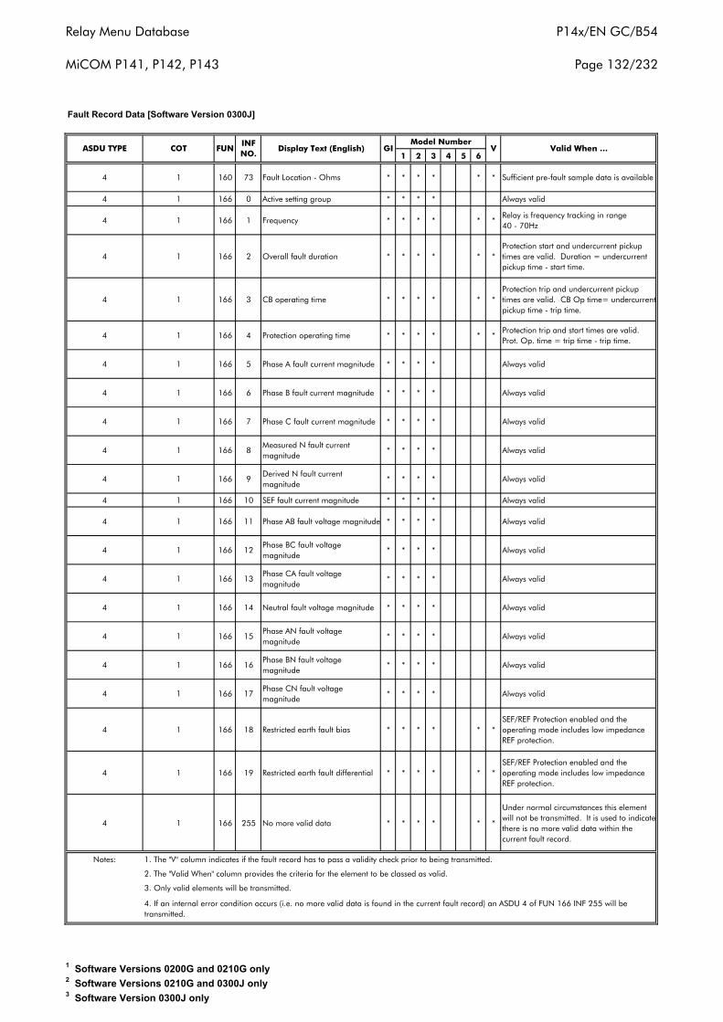
Relay Menu Database
MiCOM P141, P142, P143
P14x/EN GC/B54
Page 132/232
1 2 3 4 5 6
4 1 160 73 Fault Location - Ohms * * * * * * Sufficient pre-fault sample data is available
4 1 166 0 Active setting group * * * * Always valid
4 1 166 1 Frequency * * * * * *Relay is frequency tracking in range 40 - 70Hz
4 1 166 2 Overall fault duration * * * * * *Protection start and undercurrent pickup times are valid. Duration = undercurrent pickup time - start time.
4 1 166 3 CB operating time * * * * * *Protection trip and undercurrent pickup times are valid. CB Op time= undercurrent pickup time - trip time.
4 1 166 4 Protection operating time * * * * * *Protection trip and start times are valid. Prot. Op. time = trip time - trip time.
4 1 166 5 Phase A fault current magnitude * * * * Always valid
4 1 166 6 Phase B fault current magnitude * * * * Always valid
4 1 166 7 Phase C fault current magnitude * * * * Always valid
4 1 166 8Measured N fault current magnitude
* * * * Always valid
4 1 166 9Derived N fault current magnitude
* * * * Always valid
4 1 166 10 SEF fault current magnitude * * * * Always valid
4 1 166 11 Phase AB fault voltage magnitude * * * * Always valid
4 1 166 12Phase BC fault voltage magnitude
* * * * Always valid
4 1 166 13Phase CA fault voltage magnitude
* * * * Always valid
4 1 166 14 Neutral fault voltage magnitude * * * * Always valid
4 1 166 15Phase AN fault voltage magnitude
* * * * Always valid
4 1 166 16Phase BN fault voltage magnitude
* * * * Always valid
4 1 166 17Phase CN fault voltage magnitude
* * * * Always valid
4 1 166 18 Restricted earth fault bias * * * * * *SEF/REF Protection enabled and the operating mode includes low impedance REF protection.
4 1 166 19 Restricted earth fault differential * * * * * *SEF/REF Protection enabled and the operating mode includes low impedance REF protection.
4 1 166 255 No more valid data * * * * * *
Under normal circumstances this element will not be transmitted. It is used to indicate there is no more valid data within the current fault record.
Notes:
4. If an internal error condition occurs (i.e. no more valid data is found in the current fault record) an ASDU 4 of FUN 166 INF 255 will be transmitted.
ASDU TYPE COT FUNINF NO.
Valid When …Display Text (English) GIModel Number
V
Fault Record Data [Software Version 0300J]
1. The "V" column indicates if the fault record has to pass a validity check prior to being transmitted.
2. The "Valid When" column provides the criteria for the element to be classed as valid.
3. Only valid elements will be transmitted.
1 Software Versions 0200G and 0210G only2 Software Versions 0210G and 0300J only3 Software Version 0300J only
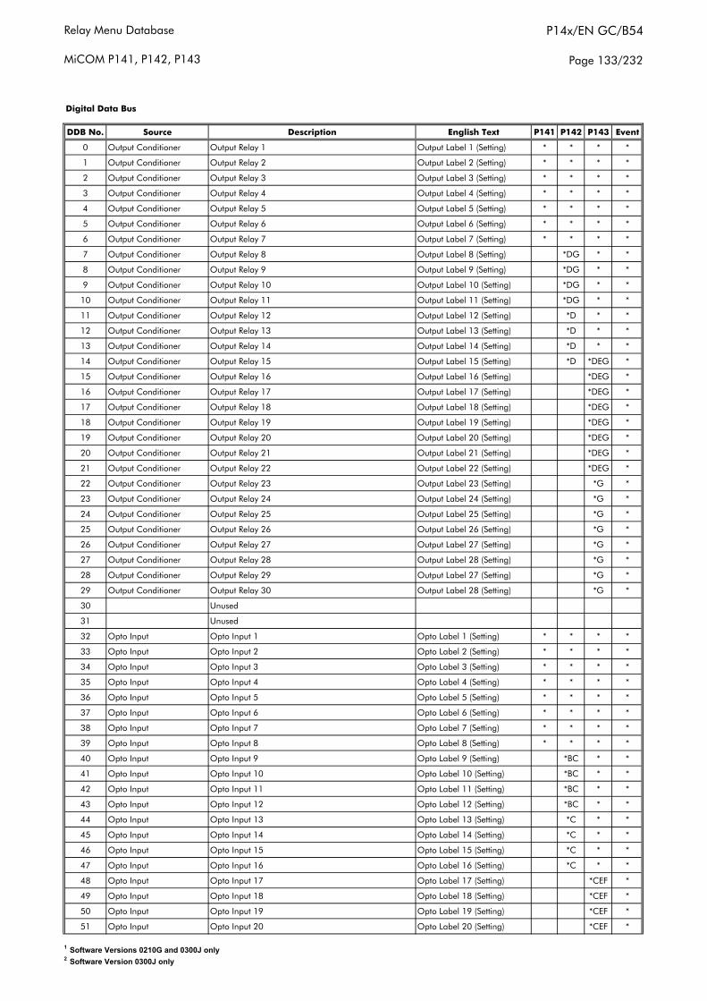
Relay Menu Database
MiCOM P141, P142, P143
P14x/EN GC/B54
Page 133/232
DDB No. Source Description English Text P141 P142 P143 Event
0 Output Conditioner Output Relay 1 Output Label 1 (Setting) * * * *
1 Output Conditioner Output Relay 2 Output Label 2 (Setting) * * * *
2 Output Conditioner Output Relay 3 Output Label 3 (Setting) * * * *
3 Output Conditioner Output Relay 4 Output Label 4 (Setting) * * * *
4 Output Conditioner Output Relay 5 Output Label 5 (Setting) * * * *
5 Output Conditioner Output Relay 6 Output Label 6 (Setting) * * * *
6 Output Conditioner Output Relay 7 Output Label 7 (Setting) * * * *
7 Output Conditioner Output Relay 8 Output Label 8 (Setting) *DG * *
8 Output Conditioner Output Relay 9 Output Label 9 (Setting) *DG * *
9 Output Conditioner Output Relay 10 Output Label 10 (Setting) *DG * *
10 Output Conditioner Output Relay 11 Output Label 11 (Setting) *DG * *
11 Output Conditioner Output Relay 12 Output Label 12 (Setting) *D * *
12 Output Conditioner Output Relay 13 Output Label 13 (Setting) *D * *
13 Output Conditioner Output Relay 14 Output Label 14 (Setting) *D * *
14 Output Conditioner Output Relay 15 Output Label 15 (Setting) *D *DEG *
15 Output Conditioner Output Relay 16 Output Label 16 (Setting) *DEG *
16 Output Conditioner Output Relay 17 Output Label 17 (Setting) *DEG *
17 Output Conditioner Output Relay 18 Output Label 18 (Setting) *DEG *
18 Output Conditioner Output Relay 19 Output Label 19 (Setting) *DEG *
19 Output Conditioner Output Relay 20 Output Label 20 (Setting) *DEG *
20 Output Conditioner Output Relay 21 Output Label 21 (Setting) *DEG *
21 Output Conditioner Output Relay 22 Output Label 22 (Setting) *DEG *
22 Output Conditioner Output Relay 23 Output Label 23 (Setting) *G *
23 Output Conditioner Output Relay 24 Output Label 24 (Setting) *G *
24 Output Conditioner Output Relay 25 Output Label 25 (Setting) *G *
25 Output Conditioner Output Relay 26 Output Label 26 (Setting) *G *
26 Output Conditioner Output Relay 27 Output Label 27 (Setting) *G *
27 Output Conditioner Output Relay 28 Output Label 28 (Setting) *G *
28 Output Conditioner Output Relay 29 Output Label 27 (Setting) *G *
29 Output Conditioner Output Relay 30 Output Label 28 (Setting) *G *
30 Unused
31 Unused
32 Opto Input Opto Input 1 Opto Label 1 (Setting) * * * *
33 Opto Input Opto Input 2 Opto Label 2 (Setting) * * * *
34 Opto Input Opto Input 3 Opto Label 3 (Setting) * * * *
35 Opto Input Opto Input 4 Opto Label 4 (Setting) * * * *
36 Opto Input Opto Input 5 Opto Label 5 (Setting) * * * *
37 Opto Input Opto Input 6 Opto Label 6 (Setting) * * * *
38 Opto Input Opto Input 7 Opto Label 7 (Setting) * * * *
39 Opto Input Opto Input 8 Opto Label 8 (Setting) * * * *
40 Opto Input Opto Input 9 Opto Label 9 (Setting) *BC * *
41 Opto Input Opto Input 10 Opto Label 10 (Setting) *BC * *
42 Opto Input Opto Input 11 Opto Label 11 (Setting) *BC * *
43 Opto Input Opto Input 12 Opto Label 12 (Setting) *BC * *
44 Opto Input Opto Input 13 Opto Label 13 (Setting) *C * *
45 Opto Input Opto Input 14 Opto Label 14 (Setting) *C * *
46 Opto Input Opto Input 15 Opto Label 15 (Setting) *C * *
47 Opto Input Opto Input 16 Opto Label 16 (Setting) *C * *
48 Opto Input Opto Input 17 Opto Label 17 (Setting) *CEF *
49 Opto Input Opto Input 18 Opto Label 18 (Setting) *CEF *
50 Opto Input Opto Input 19 Opto Label 19 (Setting) *CEF *
51 Opto Input Opto Input 20 Opto Label 20 (Setting) *CEF *
Digital Data Bus
1 Software Versions 0210G and 0300J only2 Software Version 0300J only
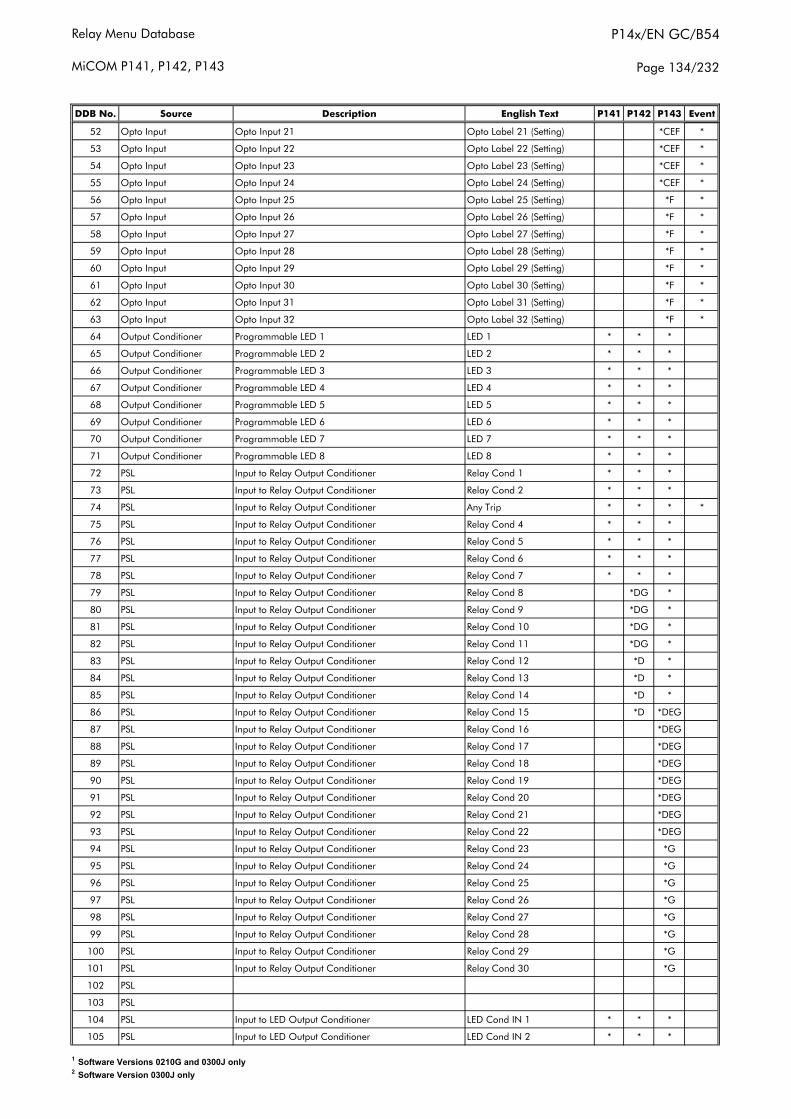
Relay Menu Database
MiCOM P141, P142, P143
P14x/EN GC/B54
Page 134/232
DDB No. Source Description English Text P141 P142 P143 Event
52 Opto Input Opto Input 21 Opto Label 21 (Setting) *CEF *
53 Opto Input Opto Input 22 Opto Label 22 (Setting) *CEF *
54 Opto Input Opto Input 23 Opto Label 23 (Setting) *CEF *
55 Opto Input Opto Input 24 Opto Label 24 (Setting) *CEF *
56 Opto Input Opto Input 25 Opto Label 25 (Setting) *F *
57 Opto Input Opto Input 26 Opto Label 26 (Setting) *F *
58 Opto Input Opto Input 27 Opto Label 27 (Setting) *F *
59 Opto Input Opto Input 28 Opto Label 28 (Setting) *F *
60 Opto Input Opto Input 29 Opto Label 29 (Setting) *F *
61 Opto Input Opto Input 30 Opto Label 30 (Setting) *F *
62 Opto Input Opto Input 31 Opto Label 31 (Setting) *F *
63 Opto Input Opto Input 32 Opto Label 32 (Setting) *F *
64 Output Conditioner Programmable LED 1 LED 1 * * *
65 Output Conditioner Programmable LED 2 LED 2 * * *
66 Output Conditioner Programmable LED 3 LED 3 * * *
67 Output Conditioner Programmable LED 4 LED 4 * * *
68 Output Conditioner Programmable LED 5 LED 5 * * *
69 Output Conditioner Programmable LED 6 LED 6 * * *
70 Output Conditioner Programmable LED 7 LED 7 * * *
71 Output Conditioner Programmable LED 8 LED 8 * * *
72 PSL Input to Relay Output Conditioner Relay Cond 1 * * *
73 PSL Input to Relay Output Conditioner Relay Cond 2 * * *
74 PSL Input to Relay Output Conditioner Any Trip * * * *
75 PSL Input to Relay Output Conditioner Relay Cond 4 * * *
76 PSL Input to Relay Output Conditioner Relay Cond 5 * * *
77 PSL Input to Relay Output Conditioner Relay Cond 6 * * *
78 PSL Input to Relay Output Conditioner Relay Cond 7 * * *
79 PSL Input to Relay Output Conditioner Relay Cond 8 *DG *
80 PSL Input to Relay Output Conditioner Relay Cond 9 *DG *
81 PSL Input to Relay Output Conditioner Relay Cond 10 *DG *
82 PSL Input to Relay Output Conditioner Relay Cond 11 *DG *
83 PSL Input to Relay Output Conditioner Relay Cond 12 *D *
84 PSL Input to Relay Output Conditioner Relay Cond 13 *D *
85 PSL Input to Relay Output Conditioner Relay Cond 14 *D *
86 PSL Input to Relay Output Conditioner Relay Cond 15 *D *DEG
87 PSL Input to Relay Output Conditioner Relay Cond 16 *DEG
88 PSL Input to Relay Output Conditioner Relay Cond 17 *DEG
89 PSL Input to Relay Output Conditioner Relay Cond 18 *DEG
90 PSL Input to Relay Output Conditioner Relay Cond 19 *DEG
91 PSL Input to Relay Output Conditioner Relay Cond 20 *DEG
92 PSL Input to Relay Output Conditioner Relay Cond 21 *DEG
93 PSL Input to Relay Output Conditioner Relay Cond 22 *DEG
94 PSL Input to Relay Output Conditioner Relay Cond 23 *G
95 PSL Input to Relay Output Conditioner Relay Cond 24 *G
96 PSL Input to Relay Output Conditioner Relay Cond 25 *G
97 PSL Input to Relay Output Conditioner Relay Cond 26 *G
98 PSL Input to Relay Output Conditioner Relay Cond 27 *G
99 PSL Input to Relay Output Conditioner Relay Cond 28 *G
100 PSL Input to Relay Output Conditioner Relay Cond 29 *G
101 PSL Input to Relay Output Conditioner Relay Cond 30 *G
102 PSL
103 PSL
104 PSL Input to LED Output Conditioner LED Cond IN 1 * * *
105 PSL Input to LED Output Conditioner LED Cond IN 2 * * *
1 Software Versions 0210G and 0300J only2 Software Version 0300J only
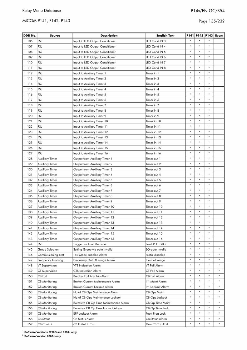
Relay Menu Database
MiCOM P141, P142, P143
P14x/EN GC/B54
Page 135/232
DDB No. Source Description English Text P141 P142 P143 Event
106 PSL Input to LED Output Conditioner LED Cond IN 3 * * *
107 PSL Input to LED Output Conditioner LED Cond IN 4 * * *
108 PSL Input to LED Output Conditioner LED Cond IN 5 * * *
109 PSL Input to LED Output Conditioner LED Cond IN 6 * * *
110 PSL Input to LED Output Conditioner LED Cond IN 7 * * *
111 PSL Input to LED Output Conditioner LED Cond IN 8 * * *
112 PSL Input to Auxiliary Timer 1 Timer in 1 * * *
113 PSL Input to Auxiliary Timer 2 Timer in 2 * * *
114 PSL Input to Auxiliary Timer 3 Timer in 3 * * *
115 PSL Input to Auxiliary Timer 4 Timer in 4 * * *
116 PSL Input to Auxiliary Timer 5 Timer in 5 * * *
117 PSL Input to Auxiliary Timer 6 Timer in 6 * * *
118 PSL Input to Auxiliary Timer 7 Timer in 7 * * *
119 PSL Input to Auxiliary Timer 8 Timer in 8 * * *
120 PSL Input to Auxiliary Timer 9 Timer in 9 * * *
121 PSL Input to Auxiliary Timer 10 Timer in 10 * * *
122 PSL Input to Auxiliary Timer 11 Timer in 11 * * *
123 PSL Input to Auxiliary Timer 12 Timer in 12 * * *
124 PSL Input to Auxiliary Timer 13 Timer in 13 * * *
125 PSL Input to Auxiliary Timer 14 Timer in 14 * * *
126 PSL Input to Auxiliary Timer 15 Timer in 15 * * *
127 PSL Input to Auxiliary Timer 16 Timer in 16 * * *
128 Auxiliary Timer Output from Auxiliary Timer 1 Timer out 1 * * *
129 Auxiliary Timer Output from Auxiliary Timer 2 Timer out 2 * * *
130 Auxiliary Timer Output from Auxiliary Timer 3 Timer out 3 * * *
131 Auxiliary Timer Output from Auxiliary Timer 4 Timer out 4 * * *
132 Auxiliary Timer Output from Auxiliary Timer 5 Timer out 5 * * *
133 Auxiliary Timer Output from Auxiliary Timer 6 Timer out 6 * * *
134 Auxiliary Timer Output from Auxiliary Timer 7 Timer out 7 * * *
135 Auxiliary Timer Output from Auxiliary Timer 8 Timer out 8 * * *
136 Auxiliary Timer Output from Auxiliary Timer 9 Timer out 9 * * *
137 Auxiliary Timer Output from Auxiliary Timer 10 Timer out 10 * * *
138 Auxiliary Timer Output from Auxiliary Timer 11 Timer out 11 * * *
139 Auxiliary Timer Output from Auxiliary Timer 12 Timer out 12 * * *
140 Auxiliary Timer Output from Auxiliary Timer 13 Timer out 13 * * *
141 Auxiliary Timer Output from Auxiliary Timer 14 Timer out 14 * * *
142 Auxiliary Timer Output from Auxiliary Timer 15 Timer out 15 * * *
143 Auxiliary Timer Output from Auxiliary Timer 16 Timer out 16 * * *
144 PSL Trigger for Fault Recorder Fault REC TRIG * * *
145 Group Selection Setting Group via opto invalid SG-opto Invalid * * * *
146 Commissioning Test Test Mode Enabled Alarm Prot'n Disabled * * * *
147 Frequency Tracking Frequency Out Of Range Alarm F out of Range * * * *
148 VT Supervision VTS Indication Alarm VT Fail Alarm * * * *
149 CT Supervision CTS Indication Alarm CT Fail Alarm * * * *
150 CB Fail Breaker Fail Any Trip Alarm CB Fail Alarm * * * *
151 CB Monitoring Broken Current Maintenance Alarm I^ Maint Alarm * * * *
152 CB Monitoring Broken Current Lockout Alarm I^ Lockout Alarm * * * *
153 CB Monitoring No of CB Ops Maintenance Alarm CB Ops Maint * * * *
154 CB Monitoring No of CB Ops Maintenance Lockout CB Ops Lockout * * * *
155 CB Monitoring Excessive CB Op Time Maintenance Alarm CB Op Time Maint * * * *
156 CB Monitoring Excessive CB Op Time Lockout Alarm CB Op Time Lock * * * *
157 CB Monitoring EFF Lockout Alarm Fault Freq Lock * * * *
158 CB Status CB Status Alarm CB Status Alarm * * * *
159 CB Control CB Failed to Trip Man CB Trip Fail * * * *
1 Software Versions 0210G and 0300J only2 Software Version 0300J only
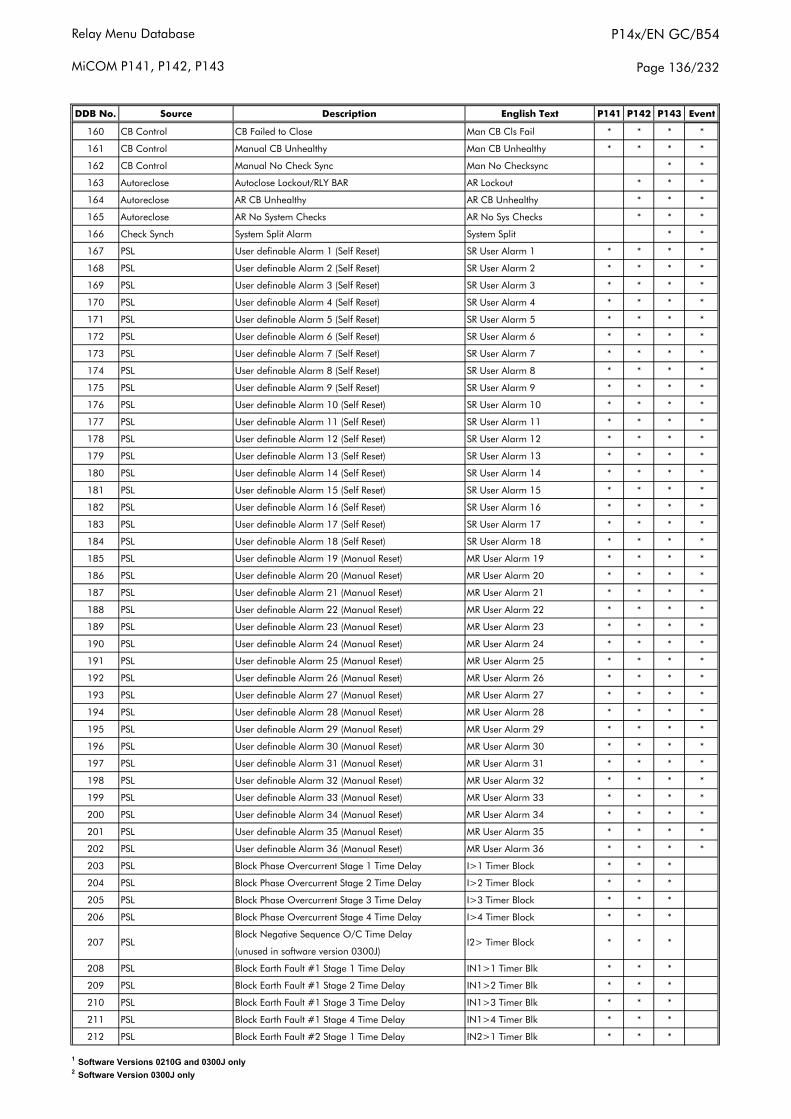
Relay Menu Database
MiCOM P141, P142, P143
P14x/EN GC/B54
Page 136/232
DDB No. Source Description English Text P141 P142 P143 Event
160 CB Control CB Failed to Close Man CB Cls Fail * * * *
161 CB Control Manual CB Unhealthy Man CB Unhealthy * * * *
162 CB Control Manual No Check Sync Man No Checksync * *
163 Autoreclose Autoclose Lockout/RLY BAR AR Lockout * * *
164 Autoreclose AR CB Unhealthy AR CB Unhealthy * * *
165 Autoreclose AR No System Checks AR No Sys Checks * * *
166 Check Synch System Split Alarm System Split * *
167 PSL User definable Alarm 1 (Self Reset) SR User Alarm 1 * * * *
168 PSL User definable Alarm 2 (Self Reset) SR User Alarm 2 * * * *
169 PSL User definable Alarm 3 (Self Reset) SR User Alarm 3 * * * *
170 PSL User definable Alarm 4 (Self Reset) SR User Alarm 4 * * * *
171 PSL User definable Alarm 5 (Self Reset) SR User Alarm 5 * * * *
172 PSL User definable Alarm 6 (Self Reset) SR User Alarm 6 * * * *
173 PSL User definable Alarm 7 (Self Reset) SR User Alarm 7 * * * *
174 PSL User definable Alarm 8 (Self Reset) SR User Alarm 8 * * * *
175 PSL User definable Alarm 9 (Self Reset) SR User Alarm 9 * * * *
176 PSL User definable Alarm 10 (Self Reset) SR User Alarm 10 * * * *
177 PSL User definable Alarm 11 (Self Reset) SR User Alarm 11 * * * *
178 PSL User definable Alarm 12 (Self Reset) SR User Alarm 12 * * * *
179 PSL User definable Alarm 13 (Self Reset) SR User Alarm 13 * * * *
180 PSL User definable Alarm 14 (Self Reset) SR User Alarm 14 * * * *
181 PSL User definable Alarm 15 (Self Reset) SR User Alarm 15 * * * *
182 PSL User definable Alarm 16 (Self Reset) SR User Alarm 16 * * * *
183 PSL User definable Alarm 17 (Self Reset) SR User Alarm 17 * * * *
184 PSL User definable Alarm 18 (Self Reset) SR User Alarm 18 * * * *
185 PSL User definable Alarm 19 (Manual Reset) MR User Alarm 19 * * * *
186 PSL User definable Alarm 20 (Manual Reset) MR User Alarm 20 * * * *
187 PSL User definable Alarm 21 (Manual Reset) MR User Alarm 21 * * * *
188 PSL User definable Alarm 22 (Manual Reset) MR User Alarm 22 * * * *
189 PSL User definable Alarm 23 (Manual Reset) MR User Alarm 23 * * * *
190 PSL User definable Alarm 24 (Manual Reset) MR User Alarm 24 * * * *
191 PSL User definable Alarm 25 (Manual Reset) MR User Alarm 25 * * * *
192 PSL User definable Alarm 26 (Manual Reset) MR User Alarm 26 * * * *
193 PSL User definable Alarm 27 (Manual Reset) MR User Alarm 27 * * * *
194 PSL User definable Alarm 28 (Manual Reset) MR User Alarm 28 * * * *
195 PSL User definable Alarm 29 (Manual Reset) MR User Alarm 29 * * * *
196 PSL User definable Alarm 30 (Manual Reset) MR User Alarm 30 * * * *
197 PSL User definable Alarm 31 (Manual Reset) MR User Alarm 31 * * * *
198 PSL User definable Alarm 32 (Manual Reset) MR User Alarm 32 * * * *
199 PSL User definable Alarm 33 (Manual Reset) MR User Alarm 33 * * * *
200 PSL User definable Alarm 34 (Manual Reset) MR User Alarm 34 * * * *
201 PSL User definable Alarm 35 (Manual Reset) MR User Alarm 35 * * * *
202 PSL User definable Alarm 36 (Manual Reset) MR User Alarm 36 * * * *
203 PSL Block Phase Overcurrent Stage 1 Time Delay I>1 Timer Block * * *
204 PSL Block Phase Overcurrent Stage 2 Time Delay I>2 Timer Block * * *
205 PSL Block Phase Overcurrent Stage 3 Time Delay I>3 Timer Block * * *
206 PSL Block Phase Overcurrent Stage 4 Time Delay I>4 Timer Block * * *
Block Negative Sequence O/C Time Delay
(unused in software version 0300J)
208 PSL Block Earth Fault #1 Stage 1 Time Delay IN1>1 Timer Blk * * *
209 PSL Block Earth Fault #1 Stage 2 Time Delay IN1>2 Timer Blk * * *
210 PSL Block Earth Fault #1 Stage 3 Time Delay IN1>3 Timer Blk * * *
211 PSL Block Earth Fault #1 Stage 4 Time Delay IN1>4 Timer Blk * * *
212 PSL Block Earth Fault #2 Stage 1 Time Delay IN2>1 Timer Blk * * *
207 PSL I2> Timer Block * * *
1 Software Versions 0210G and 0300J only2 Software Version 0300J only
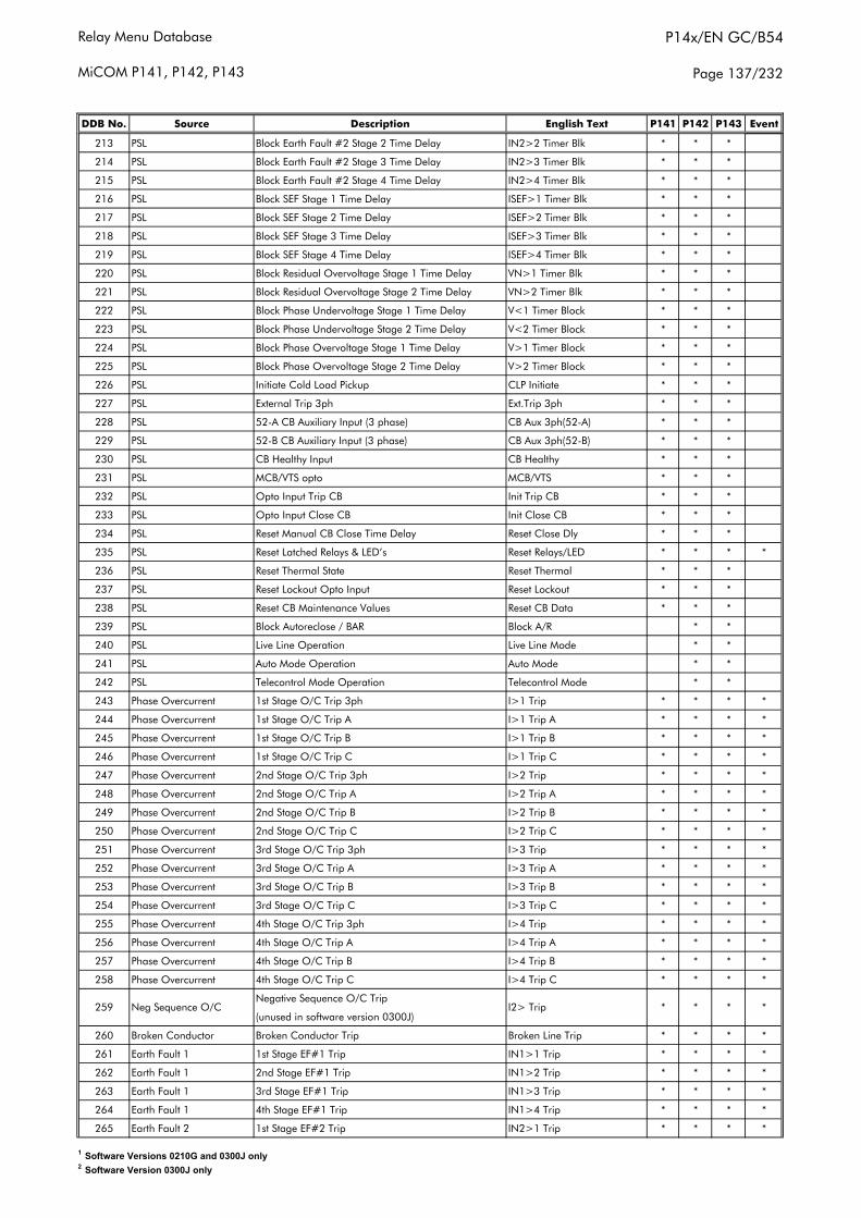
Relay Menu Database
MiCOM P141, P142, P143
P14x/EN GC/B54
Page 137/232
DDB No. Source Description English Text P141 P142 P143 Event
213 PSL Block Earth Fault #2 Stage 2 Time Delay IN2>2 Timer Blk * * *
214 PSL Block Earth Fault #2 Stage 3 Time Delay IN2>3 Timer Blk * * *
215 PSL Block Earth Fault #2 Stage 4 Time Delay IN2>4 Timer Blk * * *
216 PSL Block SEF Stage 1 Time Delay ISEF>1 Timer Blk * * *
217 PSL Block SEF Stage 2 Time Delay ISEF>2 Timer Blk * * *
218 PSL Block SEF Stage 3 Time Delay ISEF>3 Timer Blk * * *
219 PSL Block SEF Stage 4 Time Delay ISEF>4 Timer Blk * * *
220 PSL Block Residual Overvoltage Stage 1 Time Delay VN>1 Timer Blk * * *
221 PSL Block Residual Overvoltage Stage 2 Time Delay VN>2 Timer Blk * * *
222 PSL Block Phase Undervoltage Stage 1 Time Delay V<1 Timer Block * * *
223 PSL Block Phase Undervoltage Stage 2 Time Delay V<2 Timer Block * * *
224 PSL Block Phase Overvoltage Stage 1 Time Delay V>1 Timer Block * * *
225 PSL Block Phase Overvoltage Stage 2 Time Delay V>2 Timer Block * * *
226 PSL Initiate Cold Load Pickup CLP Initiate * * *
227 PSL External Trip 3ph Ext.Trip 3ph * * *
228 PSL 52-A CB Auxiliary Input (3 phase) CB Aux 3ph(52-A) * * *
229 PSL 52-B CB Auxiliary Input (3 phase) CB Aux 3ph(52-B) * * *
230 PSL CB Healthy Input CB Healthy * * *
231 PSL MCB/VTS opto MCB/VTS * * *
232 PSL Opto Input Trip CB Init Trip CB * * *
233 PSL Opto Input Close CB Init Close CB * * *
234 PSL Reset Manual CB Close Time Delay Reset Close Dly * * *
235 PSL Reset Latched Relays & LED’s Reset Relays/LED * * * *
236 PSL Reset Thermal State Reset Thermal * * *
237 PSL Reset Lockout Opto Input Reset Lockout * * *
238 PSL Reset CB Maintenance Values Reset CB Data * * *
239 PSL Block Autoreclose / BAR Block A/R * *
240 PSL Live Line Operation Live Line Mode * *
241 PSL Auto Mode Operation Auto Mode * *
242 PSL Telecontrol Mode Operation Telecontrol Mode * *
243 Phase Overcurrent 1st Stage O/C Trip 3ph I>1 Trip * * * *
244 Phase Overcurrent 1st Stage O/C Trip A I>1 Trip A * * * *
245 Phase Overcurrent 1st Stage O/C Trip B I>1 Trip B * * * *
246 Phase Overcurrent 1st Stage O/C Trip C I>1 Trip C * * * *
247 Phase Overcurrent 2nd Stage O/C Trip 3ph I>2 Trip * * * *
248 Phase Overcurrent 2nd Stage O/C Trip A I>2 Trip A * * * *
249 Phase Overcurrent 2nd Stage O/C Trip B I>2 Trip B * * * *
250 Phase Overcurrent 2nd Stage O/C Trip C I>2 Trip C * * * *
251 Phase Overcurrent 3rd Stage O/C Trip 3ph I>3 Trip * * * *
252 Phase Overcurrent 3rd Stage O/C Trip A I>3 Trip A * * * *
253 Phase Overcurrent 3rd Stage O/C Trip B I>3 Trip B * * * *
254 Phase Overcurrent 3rd Stage O/C Trip C I>3 Trip C * * * *
255 Phase Overcurrent 4th Stage O/C Trip 3ph I>4 Trip * * * *
256 Phase Overcurrent 4th Stage O/C Trip A I>4 Trip A * * * *
257 Phase Overcurrent 4th Stage O/C Trip B I>4 Trip B * * * *
258 Phase Overcurrent 4th Stage O/C Trip C I>4 Trip C * * * *
Negative Sequence O/C Trip
(unused in software version 0300J)
260 Broken Conductor Broken Conductor Trip Broken Line Trip * * * *
261 Earth Fault 1 1st Stage EF#1 Trip IN1>1 Trip * * * *
262 Earth Fault 1 2nd Stage EF#1 Trip IN1>2 Trip * * * *
263 Earth Fault 1 3rd Stage EF#1 Trip IN1>3 Trip * * * *
264 Earth Fault 1 4th Stage EF#1 Trip IN1>4 Trip * * * *
265 Earth Fault 2 1st Stage EF#2 Trip IN2>1 Trip * * * *
* *I2> Trip259 Neg Sequence O/C * *
1 Software Versions 0210G and 0300J only2 Software Version 0300J only
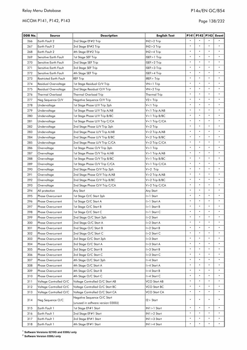
Relay Menu Database
MiCOM P141, P142, P143
P14x/EN GC/B54
Page 138/232
DDB No. Source Description English Text P141 P142 P143 Event
266 Earth Fault 2 2nd Stage EF#2 Trip IN2>2 Trip * * * *
267 Earth Fault 2 3rd Stage EF#2 Trip IN2>3 Trip * * * *
268 Earth Fault 2 4th Stage EF#2 Trip IN2>4 Trip * * * *
269 Sensitive Earth Fault 1st Stage SEF Trip ISEF>1 Trip * * * *
270 Sensitive Earth Fault 2nd Stage SEF Trip ISEF>2 Trip * * * *
271 Sensitive Earth Fault 3rd Stage SEF Trip ISEF>3 Trip * * * *
272 Sensitive Earth Fault 4th Stage SEF Trip ISEF>4 Trip * * * *
273 Restricted Earth Fault REF Trip IREF> Trip * * * *
274 Residual Overvoltage 1st Stage Residual O/V Trip VN>1 Trip * * * *
275 Residual Overvoltage 2nd Stage Residual O/V Trip VN>2 Trip * * * *
276 Thermal Overload Thermal Overload Trip Thermal Trip * * * *
277 Neg Sequence O/V Negative Sequence O/V Trip V2> Trip * * * *
278 Undervoltage 1st Stage Phase U/V Trip 3ph V<1 Trip * * * *
279 Undervoltage 1st Stage Phase U/V Trip A/AB V<1 Trip A/AB * * * *
280 Undervoltage 1st Stage Phase U/V Trip B/BC V<1 Trip B/BC * * * *
281 Undervoltage 1st Stage Phase U/V Trip C/CA V<1 Trip C/CA * * * *
282 Undervoltage 2nd Stage Phase U/V Trip 3ph V<2 Trip * * * *
283 Undervoltage 2nd Stage Phase U/V Trip A/AB V<2 Trip A/AB * * * *
284 Undervoltage 2nd Stage Phase U/V Trip B/BC V<2 Trip B/BC * * * *
285 Undervoltage 2nd Stage Phase U/V Trip C/CA V<2 Trip C/CA * * * *
286 Overvoltage 1st Stage Phase O/V Trip 3ph V>1 Trip * * * *
287 Overvoltage 1st Stage Phase O/V Trip A/AB V>1 Trip A/AB * * * *
288 Overvoltage 1st Stage Phase O/V Trip B/BC V>1 Trip B/BC * * * *
289 Overvoltage 1st Stage Phase O/V Trip C/CA V>1 Trip C/CA * * * *
290 Overvoltage 2nd Stage Phase O/V Trip 3ph V>2 Trip * * * *
291 Overvoltage 2nd Stage Phase O/V Trip A/AB V>2 Trip A/AB * * * *
292 Overvoltage 2nd Stage Phase O/V Trip B/BC V>2 Trip B/BC * * * *
293 Overvoltage 2nd Stage Phase O/V Trip C/CA V>2 Trip C/CA * * * *
294 All protection Any Start Any Start * * * *
295 Phase Overcurrent 1st Stage O/C Start 3ph I>1 Start * * * *
296 Phase Overcurrent 1st Stage O/C Start A I>1 Start A * * * *
297 Phase Overcurrent 1st Stage O/C Start B I>1 Start B * * * *
298 Phase Overcurrent 1st Stage O/C Start C I>1 Start C * * * *
299 Phase Overcurrent 2nd Stage O/C Start 3ph I>2 Start * * * *
300 Phase Overcurrent 2nd Stage O/C Start A I>2 Start A * * * *
301 Phase Overcurrent 2nd Stage O/C Start B I>2 Start B * * * *
302 Phase Overcurrent 2nd Stage O/C Start C I>2 Start C * * * *
303 Phase Overcurrent 3rd Stage O/C Start 3ph I>3 Start * * * *
304 Phase Overcurrent 3rd Stage O/C Start A I>3 Start A * * * *
305 Phase Overcurrent 3rd Stage O/C Start B I>3 Start B * * * *
306 Phase Overcurrent 3rd Stage O/C Start C I>3 Start C * * * *
307 Phase Overcurrent 4th Stage O/C Start 3ph I>4 Start * * * *
308 Phase Overcurrent 4th Stage O/C Start A I>4 Start A * * * *
309 Phase Overcurrent 4th Stage O/C Start B I>4 Start B * * * *
310 Phase Overcurrent 4th Stage O/C Start C I>4 Start C * * * *
311 Voltage Controlled O/C Voltage Controlled O/C Start AB VCO Start AB * * * *
312 Voltage Controlled O/C Voltage Controlled O/C Start BC VCO Start BC * * * *
313 Voltage Controlled O/C Voltage Controlled O/C Start CA VCO Start CA * * * *
Negative Sequence O/C Start
(unused in software version 0300J)
315 Earth Fault 1 1st Stage EF#1 Start IN1>1 Start * * * *
316 Earth Fault 1 2nd Stage EF#1 Start IN1>2 Start * * * *
317 Earth Fault 1 3rd Stage EF#1 Start IN1>3 Start * * * *
318 Earth Fault 1 4th Stage EF#1 Start IN1>4 Start * * * *
314 Neg Sequence O/C * * * *I2> Start
1 Software Versions 0210G and 0300J only2 Software Version 0300J only
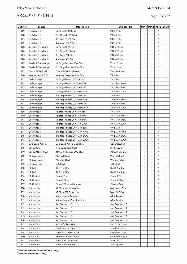
Relay Menu Database
MiCOM P141, P142, P143
P14x/EN GC/B54
Page 139/232
DDB No. Source Description English Text P141 P142 P143 Event
319 Earth Fault 2 1st Stage EF#2 Start IN2>1 Start * * * *
320 Earth Fault 2 2nd Stage EF#2 Start IN2>2 Start * * * *
321 Earth Fault 2 3rd Stage EF#2 Start IN2>3 Start * * * *
322 Earth Fault 2 4th Stage EF#2 Start IN2>4 Start * * * *
323 Sensitive Earth Fault 1st Stage SEF Start ISEF>1 Start * * * *
324 Sensitive Earth Fault 2nd Stage SEF Start ISEF>2 Start * * * *
325 Sensitive Earth Fault 3rd Stage SEF Start ISEF>3 Start * * * *
326 Sensitive Earth Fault 4th Stage SEF Start ISEF>4 Start * * * *
327 Residual Overvoltage 1st Stage Residual O/V Start VN>1 Start * * * *
328 Residual Overvoltage 2nd Stage Residual O/V Start VN>2 Start * * * *
329 Thermal Overload Thermal Overload Alarm Thermal Alarm * * * *
330 Neg Sequence O/V Negative Sequence O/V Start V2> Start * * * *
331 Undervoltage 1st Stage Phase U/V Start 3ph V<1 Start * * * *
332 Undervoltage 1st Stage Phase U/V Start A/AB V<1 Start A/AB * * * *
333 Undervoltage 1st Stage Phase U/V Start B/BC V<1 Start B/BC * * * *
334 Undervoltage 1st Stage Phase U/V Start C/CA V<1 Start C/CA * * * *
335 Undervoltage 2nd Stage Phase U/V Start 3ph V<2 Start * * * *
336 Undervoltage 2nd Stage Phase U/V Start A/AB V<2 Start A/AB * * * *
337 Undervoltage 2nd Stage Phase U/V Start B/BC V<2 Start B/BC * * * *
338 Undervoltage 2nd Stage Phase U/V Start C/CA V<2 Start C/CA * * * *
339 Overvoltage 1st Stage Phase O/V Start 3ph V>1 Start * * * *
340 Overvoltage 1st Stage Phase O/V Start A/AB V>1 Start A/AB * * * *
341 Overvoltage 1st Stage Phase O/V Start B/BC V>1 Start B/BC * * * *
342 Overvoltage 1st Stage Phase O/V Start C/CA V>1 Start C/CA * * * *
343 Overvoltage 2nd Stage Phase O/V Start 3ph V>2 Start * * * *
344 Overvoltage 2nd Stage Phase O/V Start A/AB V>2 Start A/AB * * * *
345 Overvoltage 2nd Stage Phase O/V Start B/BC V>2 Start B/BC * * * *
346 Overvoltage 2nd Stage Phase O/V Start C/CA V>2 Start C/CA * * * *
347 Cold Load Pickup Cold Load Pickup Operation CLP Operation * * * *
348 CBF & POC I> Blocked O/C Start I> BlockStart * * * *
349 CBF & IN1/IN2/SEF IN/ISEF> Blocked O/C Start IN/SEF>Blk Start * * * *
350 VT Supervision VTS Fast Block VTS Fast Block * * *
351 VT Supervision VTS Slow Block VTS Slow Block * * *
352 CT Supervision CTS Block CTS Block * * *
353 CB Fail tBF1 Trip 3Ph Bfail1 Trip 3ph * * * *
354 CB Fail tBF2 Trip 3Ph Bfail2 Trip 3ph * * * *
355 CB Control Control Trip Control Trip * * * *
356 CB Control Control Close Control Close * * * *
357 CB Control Control Close in Progress Close in Prog * * * *
358 Autoreclose AR Block Main Protection Block Main Prot * * *
359 Autoreclose AR Block SEF Protection Block SEF Prot * * *
360 Autoreclose Autoreclose In Progress AR In Progress * * *
361 Autoreclose Autoreclose In/Out of service AR In Service * * *
362 Autoreclose Seq Counter = 0 Seq Counter = 0 * *
363 Autoreclose Seq Counter = 1 Seq Counter = 1 * * *
364 Autoreclose Seq Counter = 2 Seq Counter = 2 * * *
365 Autoreclose Seq Counter = 3 Seq Counter = 3 * * *
366 Autoreclose Seq Counter = 4 Seq Counter = 4 * * *
367 Autoreclose Successful Reclosure Successful Close * * *
368 Autoreclose Dead Time in Progress Dead T in Prog * * *
369 Autoreclose Protection Lockout of AR Protection Lockt * * *
370 Autoreclose AR Reset Lockout Alarm Reset Lckout Alm * * *
371 Autoreclose Auto Close/ AR Close Auto Close * * *
372 Autoreclose Autoreclose trip test A/R Trip Test * * *
1 Software Versions 0210G and 0300J only2 Software Version 0300J only
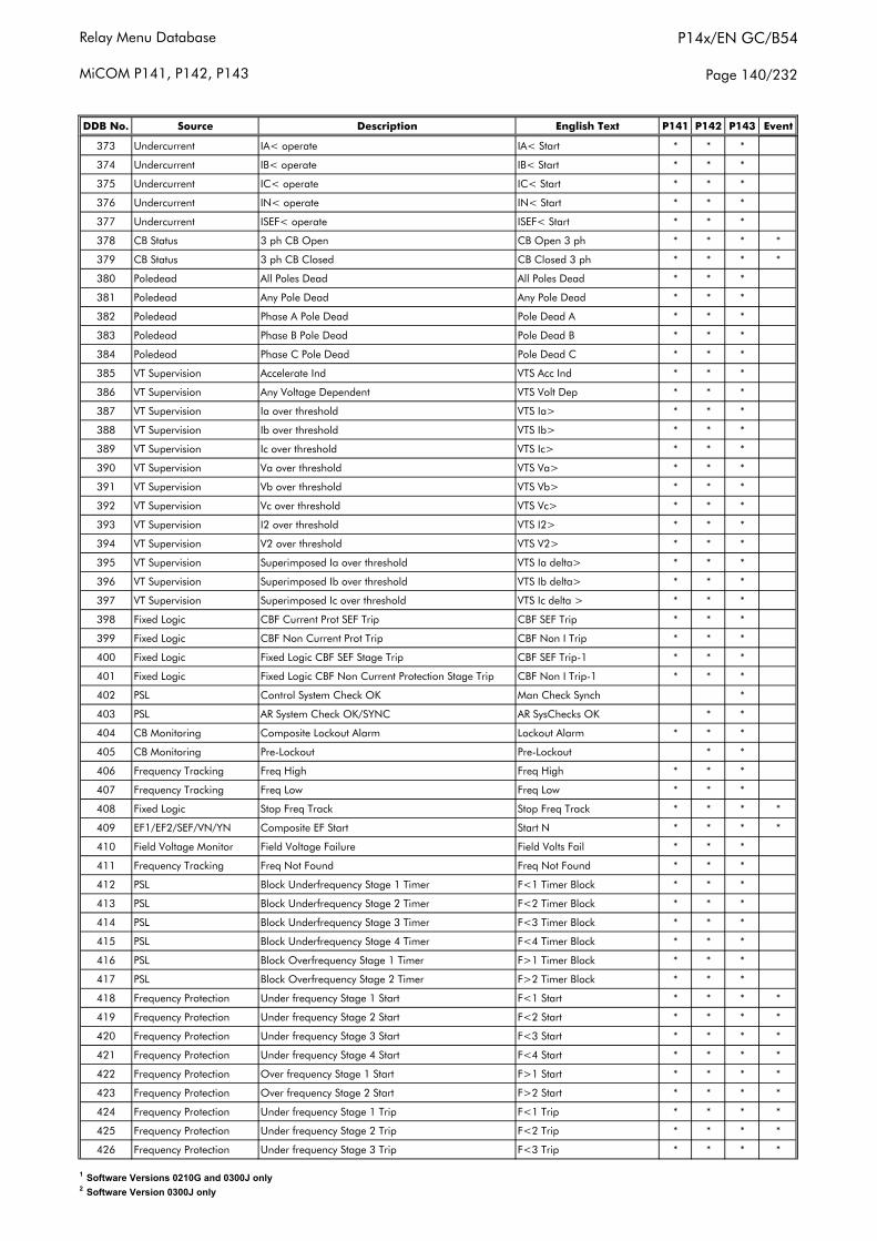
Relay Menu Database
MiCOM P141, P142, P143
P14x/EN GC/B54
Page 140/232
DDB No. Source Description English Text P141 P142 P143 Event
373 Undercurrent IA< operate IA< Start * * *
374 Undercurrent IB< operate IB< Start * * *
375 Undercurrent IC< operate IC< Start * * *
376 Undercurrent IN< operate IN< Start * * *
377 Undercurrent ISEF< operate ISEF< Start * * *
378 CB Status 3 ph CB Open CB Open 3 ph * * * *
379 CB Status 3 ph CB Closed CB Closed 3 ph * * * *
380 Poledead All Poles Dead All Poles Dead * * *
381 Poledead Any Pole Dead Any Pole Dead * * *
382 Poledead Phase A Pole Dead Pole Dead A * * *
383 Poledead Phase B Pole Dead Pole Dead B * * *
384 Poledead Phase C Pole Dead Pole Dead C * * *
385 VT Supervision Accelerate Ind VTS Acc Ind * * *
386 VT Supervision Any Voltage Dependent VTS Volt Dep * * *
387 VT Supervision Ia over threshold VTS Ia> * * *
388 VT Supervision Ib over threshold VTS Ib> * * *
389 VT Supervision Ic over threshold VTS Ic> * * *
390 VT Supervision Va over threshold VTS Va> * * *
391 VT Supervision Vb over threshold VTS Vb> * * *
392 VT Supervision Vc over threshold VTS Vc> * * *
393 VT Supervision I2 over threshold VTS I2> * * *
394 VT Supervision V2 over threshold VTS V2> * * *
395 VT Supervision Superimposed Ia over threshold VTS Ia delta> * * *
396 VT Supervision Superimposed Ib over threshold VTS Ib delta> * * *
397 VT Supervision Superimposed Ic over threshold VTS Ic delta > * * *
398 Fixed Logic CBF Current Prot SEF Trip CBF SEF Trip * * *
399 Fixed Logic CBF Non Current Prot Trip CBF Non I Trip * * *
400 Fixed Logic Fixed Logic CBF SEF Stage Trip CBF SEF Trip-1 * * *
401 Fixed Logic Fixed Logic CBF Non Current Protection Stage Trip CBF Non I Trip-1 * * *
402 PSL Control System Check OK Man Check Synch *
403 PSL AR System Check OK/SYNC AR SysChecks OK * *
404 CB Monitoring Composite Lockout Alarm Lockout Alarm * * *
405 CB Monitoring Pre-Lockout Pre-Lockout * *
406 Frequency Tracking Freq High Freq High * * *
407 Frequency Tracking Freq Low Freq Low * * *
408 Fixed Logic Stop Freq Track Stop Freq Track * * * *
409 EF1/EF2/SEF/VN/YN Composite EF Start Start N * * * *
410 Field Voltage Monitor Field Voltage Failure Field Volts Fail * * *
411 Frequency Tracking Freq Not Found Freq Not Found * * *
412 PSL Block Underfrequency Stage 1 Timer F<1 Timer Block * * *
413 PSL Block Underfrequency Stage 2 Timer F<2 Timer Block * * *
414 PSL Block Underfrequency Stage 3 Timer F<3 Timer Block * * *
415 PSL Block Underfrequency Stage 4 Timer F<4 Timer Block * * *
416 PSL Block Overfrequency Stage 1 Timer F>1 Timer Block * * *
417 PSL Block Overfrequency Stage 2 Timer F>2 Timer Block * * *
418 Frequency Protection Under frequency Stage 1 Start F<1 Start * * * *
419 Frequency Protection Under frequency Stage 2 Start F<2 Start * * * *
420 Frequency Protection Under frequency Stage 3 Start F<3 Start * * * *
421 Frequency Protection Under frequency Stage 4 Start F<4 Start * * * *
422 Frequency Protection Over frequency Stage 1 Start F>1 Start * * * *
423 Frequency Protection Over frequency Stage 2 Start F>2 Start * * * *
424 Frequency Protection Under frequency Stage 1 Trip F<1 Trip * * * *
425 Frequency Protection Under frequency Stage 2 Trip F<2 Trip * * * *
426 Frequency Protection Under frequency Stage 3 Trip F<3 Trip * * * *
1 Software Versions 0210G and 0300J only2 Software Version 0300J only
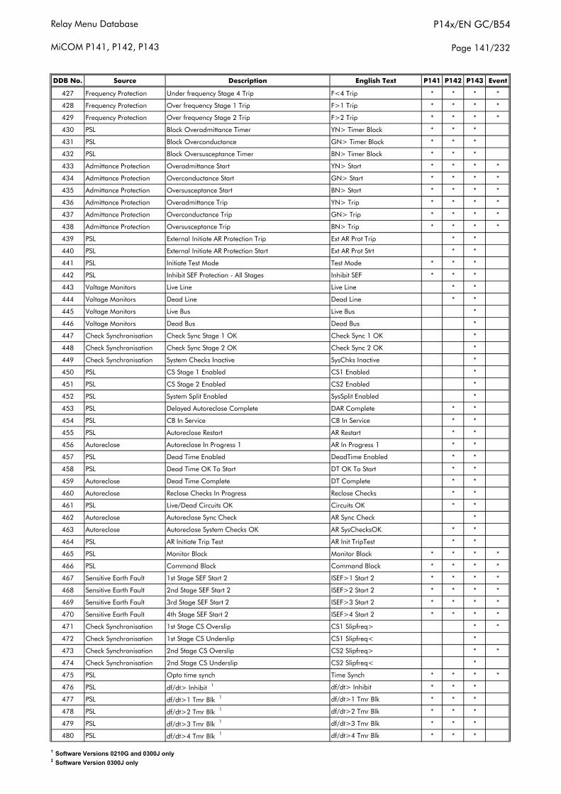
Relay Menu Database
MiCOM P141, P142, P143
P14x/EN GC/B54
Page 141/232
DDB No. Source Description English Text P141 P142 P143 Event
427 Frequency Protection Under frequency Stage 4 Trip F<4 Trip * * * *
428 Frequency Protection Over frequency Stage 1 Trip F>1 Trip * * * *
429 Frequency Protection Over frequency Stage 2 Trip F>2 Trip * * * *
430 PSL Block Overadmittance Timer YN> Timer Block * * *
431 PSL Block Overconductance GN> Timer Block * * *
432 PSL Block Oversusceptance Timer BN> Timer Block * * *
433 Admittance Protection Overadmittance Start YN> Start * * * *
434 Admittance Protection Overconductance Start GN> Start * * * *
435 Admittance Protection Oversusceptance Start BN> Start * * * *
436 Admittance Protection Overadmittance Trip YN> Trip * * * *
437 Admittance Protection Overconductance Trip GN> Trip * * * *
438 Admittance Protection Oversusceptance Trip BN> Trip * * * *
439 PSL External Initiate AR Protection Trip Ext AR Prot Trip * *
440 PSL External Initiate AR Protection Start Ext AR Prot Strt * *
441 PSL Initiate Test Mode Test Mode * * *
442 PSL Inhibit SEF Protection - All Stages Inhibit SEF * * *
443 Voltage Monitors Live Line Live Line * *
444 Voltage Monitors Dead Line Dead Line * *
445 Voltage Monitors Live Bus Live Bus *
446 Voltage Monitors Dead Bus Dead Bus *
447 Check Synchronisation Check Sync Stage 1 OK Check Sync 1 OK *
448 Check Synchronisation Check Sync Stage 2 OK Check Sync 2 OK *
449 Check Synchronisation System Checks Inactive SysChks Inactive *
450 PSL CS Stage 1 Enabled CS1 Enabled *
451 PSL CS Stage 2 Enabled CS2 Enabled *
452 PSL System Split Enabled SysSplit Enabled *
453 PSL Delayed Autoreclose Complete DAR Complete * *
454 PSL CB In Service CB In Service * *
455 PSL Autoreclose Restart AR Restart * *
456 Autoreclose Autoreclose In Progress 1 AR In Progress 1 * *
457 PSL Dead Time Enabled DeadTime Enabled * *
458 PSL Dead Time OK To Start DT OK To Start * *
459 Autoreclose Dead Time Complete DT Complete * *
460 Autoreclose Reclose Checks In Progress Reclose Checks * *
461 PSL Live/Dead Circuits OK Circuits OK * *
462 Autoreclose Autoreclose Sync Check AR Sync Check *
463 Autoreclose Autoreclose System Checks OK AR SysChecksOK * *
464 PSL AR Initiate Trip Test AR Init TripTest * *
465 PSL Monitor Block Monitor Block * * * *
466 PSL Command Block Command Block * * * *
467 Sensitive Earth Fault 1st Stage SEF Start 2 ISEF>1 Start 2 * * * *
468 Sensitive Earth Fault 2nd Stage SEF Start 2 ISEF>2 Start 2 * * * *
469 Sensitive Earth Fault 3rd Stage SEF Start 2 ISEF>3 Start 2 * * * *
470 Sensitive Earth Fault 4th Stage SEF Start 2 ISEF>4 Start 2 * * * *
471 Check Synchronisation 1st Stage CS Overslip CS1 Slipfreq> * *
472 Check Synchronisation 1st Stage CS Underslip CS1 Slipfreq< *
473 Check Synchronisation 2nd Stage CS Overslip CS2 Slipfreq> * *
474 Check Synchronisation 2nd Stage CS Underslip CS2 Slipfreq< *
475 PSL Opto time synch Time Synch * * * *
476 PSL df/dt> Inhibit 1 df/dt> Inhibit * * *
477 PSL df/dt>1 Tmr Blk 1 df/dt>1 Tmr Blk * * *
478 PSL df/dt>2 Tmr Blk 1 df/dt>2 Tmr Blk * * *
479 PSL df/dt>3 Tmr Blk 1 df/dt>3 Tmr Blk * * *
480 PSL df/dt>4 Tmr Blk 1 df/dt>4 Tmr Blk * * *
1 Software Versions 0210G and 0300J only2 Software Version 0300J only
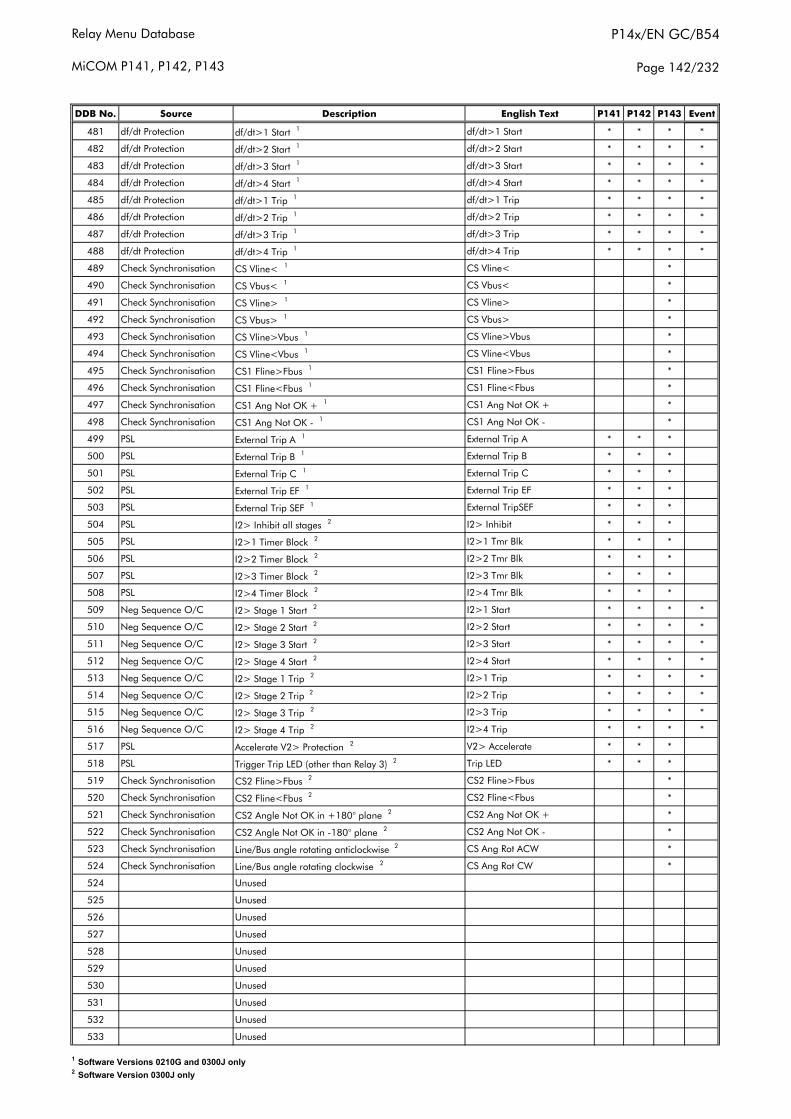
Relay Menu Database
MiCOM P141, P142, P143
P14x/EN GC/B54
Page 142/232
DDB No. Source Description English Text P141 P142 P143 Event
481 df/dt Protection df/dt>1 Start 1 df/dt>1 Start * * * *
482 df/dt Protection df/dt>2 Start 1 df/dt>2 Start * * * *
483 df/dt Protection df/dt>3 Start 1 df/dt>3 Start * * * *
484 df/dt Protection df/dt>4 Start 1 df/dt>4 Start * * * *
485 df/dt Protection df/dt>1 Trip 1 df/dt>1 Trip * * * *
486 df/dt Protection df/dt>2 Trip 1 df/dt>2 Trip * * * *
487 df/dt Protection df/dt>3 Trip 1 df/dt>3 Trip * * * *
488 df/dt Protection df/dt>4 Trip 1 df/dt>4 Trip * * * *
489 Check Synchronisation CS Vline< 1 CS Vline< *
490 Check Synchronisation CS Vbus< 1 CS Vbus< *
491 Check Synchronisation CS Vline> 1 CS Vline> *
492 Check Synchronisation CS Vbus> 1 CS Vbus> *
493 Check Synchronisation CS Vline>Vbus 1 CS Vline>Vbus *
494 Check Synchronisation CS Vline<Vbus 1 CS Vline<Vbus *
495 Check Synchronisation CS1 Fline>Fbus 1 CS1 Fline>Fbus *
496 Check Synchronisation CS1 Fline<Fbus 1 CS1 Fline<Fbus *
497 Check Synchronisation CS1 Ang Not OK + 1 CS1 Ang Not OK + *
498 Check Synchronisation CS1 Ang Not OK - 1 CS1 Ang Not OK - *
499 PSL External Trip A 1 External Trip A * * *
500 PSL External Trip B 1 External Trip B * * *
501 PSL External Trip C 1 External Trip C * * *
502 PSL External Trip EF 1 External Trip EF * * *
503 PSL External Trip SEF 1 External TripSEF * * *
504 PSL I2> Inhibit all stages 2 I2> Inhibit * * *
505 PSL I2>1 Timer Block 2 I2>1 Tmr Blk * * *
506 PSL I2>2 Timer Block 2 I2>2 Tmr Blk * * *
507 PSL I2>3 Timer Block 2 I2>3 Tmr Blk * * *
508 PSL I2>4 Timer Block 2 I2>4 Tmr Blk * * *
509 Neg Sequence O/C I2> Stage 1 Start 2 I2>1 Start * * * *
510 Neg Sequence O/C I2> Stage 2 Start 2 I2>2 Start * * * *
511 Neg Sequence O/C I2> Stage 3 Start 2 I2>3 Start * * * *
512 Neg Sequence O/C I2> Stage 4 Start 2 I2>4 Start * * * *
513 Neg Sequence O/C I2> Stage 1 Trip 2 I2>1 Trip * * * *
514 Neg Sequence O/C I2> Stage 2 Trip 2 I2>2 Trip * * * *
515 Neg Sequence O/C I2> Stage 3 Trip 2 I2>3 Trip * * * *
516 Neg Sequence O/C I2> Stage 4 Trip 2 I2>4 Trip * * * *
517 PSL Accelerate V2> Protection 2 V2> Accelerate * * *
518 PSL Trigger Trip LED (other than Relay 3) 2 Trip LED * * *
519 Check Synchronisation CS2 Fline>Fbus 2 CS2 Fline>Fbus *
520 Check Synchronisation CS2 Fline<Fbus 2 CS2 Fline<Fbus *
521 Check Synchronisation CS2 Angle Not OK in +180° plane 2 CS2 Ang Not OK + *
522 Check Synchronisation CS2 Angle Not OK in -180° plane 2 CS2 Ang Not OK - *
523 Check Synchronisation Line/Bus angle rotating anticlockwise 2 CS Ang Rot ACW *
524 Check Synchronisation Line/Bus angle rotating clockwise 2 CS Ang Rot CW *
524 Unused
525 Unused
526 Unused
527 Unused
528 Unused
529 Unused
530 Unused
531 Unused
532 Unused
533 Unused
1 Software Versions 0210G and 0300J only2 Software Version 0300J only

Relay Menu Database
MiCOM P141, P142, P143
P14x/EN GC/B54
Page 143/232
DDB No. Source Description English Text P141 P142 P143 Event
534 Unused
535 Unused
536 Unused
537 Unused
538 Unused
539 Unused
540 Unused
541 Unused
542 Unused
543 Unused
544 Unused
545 Unused
546 Unused
547 Unused
548 Unused
549 Unused
550 Unused
551 Unused
552 Unused
553 Unused
554 Unused
555 Unused
556 Unused
557 Unused
558 Unused
559 Unused
560 Unused
561 Unused
562 Unused
563 Unused
564 Unused
565 Unused
566 Unused
567 Unused
568 Unused
569 Unused
570 Unused
571 Unused
572 Unused
573 Unused
574 Unused
575 Unused
576 Unused
577 Unused
578 Unused
579 Unused
580 Unused
581 Unused
582 Unused
583 Unused
584 Unused
585 Unused
586 Unused
587 Unused
1 Software Versions 0210G and 0300J only2 Software Version 0300J only
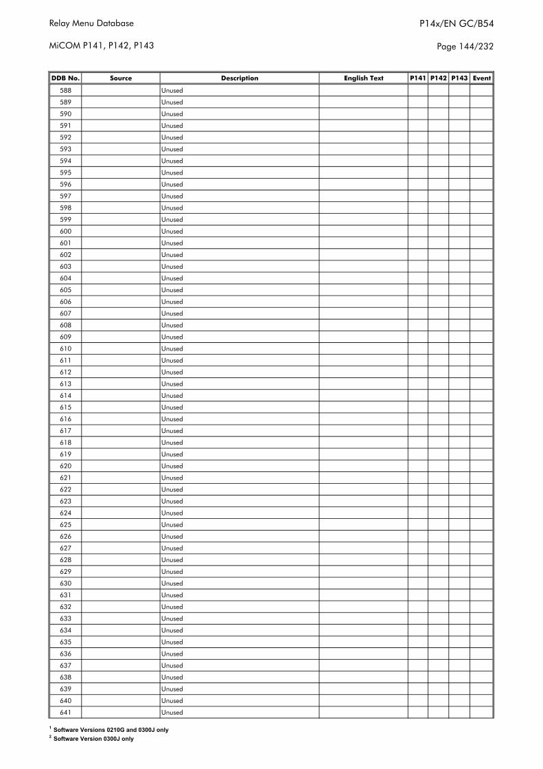
Relay Menu Database
MiCOM P141, P142, P143
P14x/EN GC/B54
Page 144/232
DDB No. Source Description English Text P141 P142 P143 Event
588 Unused
589 Unused
590 Unused
591 Unused
592 Unused
593 Unused
594 Unused
595 Unused
596 Unused
597 Unused
598 Unused
599 Unused
600 Unused
601 Unused
602 Unused
603 Unused
604 Unused
605 Unused
606 Unused
607 Unused
608 Unused
609 Unused
610 Unused
611 Unused
612 Unused
613 Unused
614 Unused
615 Unused
616 Unused
617 Unused
618 Unused
619 Unused
620 Unused
621 Unused
622 Unused
623 Unused
624 Unused
625 Unused
626 Unused
627 Unused
628 Unused
629 Unused
630 Unused
631 Unused
632 Unused
633 Unused
634 Unused
635 Unused
636 Unused
637 Unused
638 Unused
639 Unused
640 Unused
641 Unused
1 Software Versions 0210G and 0300J only2 Software Version 0300J only

Relay Menu Database
MiCOM P141, P142, P143
P14x/EN GC/B54
Page 145/232
DDB No. Source Description English Text P141 P142 P143 Event
642 Unused
643 Unused
644 Unused
645 Unused
646 Unused
647 Unused
648 Unused
649 Unused
650 Unused
651 Unused
652 Unused
653 Unused
654 Unused
655 Unused
656 Unused
657 Unused
658 Unused
659 Unused
660 Unused
661 Unused
662 Unused
663 Unused
664 Unused
665 Unused
666 Unused
667 Unused
668 Unused
669 Unused
670 Unused
671 Unused
672 Unused
673 Unused
674 Unused
675 Unused
676 Unused
677 Unused
678 Unused
679 Unused
680 Unused
681 Unused
682 Unused
683 Unused
684 Unused
685 Unused
686 Unused
687 Unused
688 Unused
689 Unused
690 Unused
691 Unused
692 Unused
693 Unused
694 Unused
695 Unused
1 Software Versions 0210G and 0300J only2 Software Version 0300J only

Relay Menu Database
MiCOM P141, P142, P143
P14x/EN GC/B54
Page 146/232
DDB No. Source Description English Text P141 P142 P143 Event
696 Unused
697 Unused
698 Unused
699 Unused
700 Unused
701 Unused
702 Unused
703 Unused
704 Unused
705 Unused
706 Unused
707 Unused
708 Unused
709 Unused
710 Unused
711 Unused
712 Unused
713 Unused
714 Unused
715 Unused
716 Unused
717 Unused
718 Unused
719 Unused
720 Unused
721 Unused
722 Unused
723 Unused
724 Unused
725 Unused
726 Unused
727 Unused
728 Unused
729 Unused
730 Unused
731 Unused
732 Unused
733 Unused
734 Unused
735 Unused
736 Unused
737 Unused
738 Unused
739 Unused
740 Unused
741 Unused
742 Unused
743 Unused
744 Unused
745 Unused
746 Unused
747 Unused
748 Unused
749 Unused
1 Software Versions 0210G and 0300J only2 Software Version 0300J only
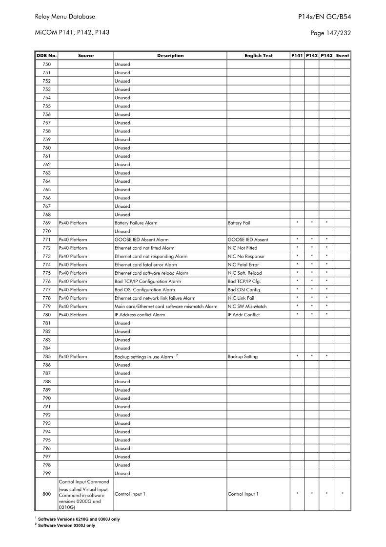
Relay Menu Database
MiCOM P141, P142, P143
P14x/EN GC/B54
Page 147/232
DDB No. Source Description English Text P141 P142 P143 Event
750 Unused
751 Unused
752 Unused
753 Unused
754 Unused
755 Unused
756 Unused
757 Unused
758 Unused
759 Unused
760 Unused
761 Unused
762 Unused
763 Unused
764 Unused
765 Unused
766 Unused
767 Unused
768 Unused
769 Px40 Platform Battery Failure Alarm Battery Fail * * *
770 Unused
771 Px40 Platform GOOSE IED Absent Alarm GOOSE IED Absent * * *
772 Px40 Platform Ethernet card not fitted Alarm NIC Not Fitted * * *
773 Px40 Platform Ethernet card not responding Alarm NIC No Response * * *
774 Px40 Platform Ethernet card fatal error Alarm NIC Fatal Error * * *
775 Px40 Platform Ethernet card software reload Alarm NIC Soft. Reload * * *
776 Px40 Platform Bad TCP/IP Configuration Alarm Bad TCP/IP Cfg. * * *
777 Px40 Platform Bad OSI Configuration Alarm Bad OSI Config. * * *
778 Px40 Platform Ethernet card network link failure Alarm NIC Link Fail * * *
779 Px40 Platform Main card/Ethernet card software mismatch Alarm NIC SW Mis-Match * * *
780 Px40 Platform IP Address conflict Alarm IP Addr Conflict * * *
781 Unused
782 Unused
783 Unused
784 Unused
785 Px40 Platform Backup settings in use Alarm 2 Backup Setting * * *
786 Unused
787 Unused
788 Unused
789 Unused
790 Unused
791 Unused
792 Unused
793 Unused
794 Unused
795 Unused
796 Unused
797 Unused
798 Unused
799 Unused
Control Input Command
(was called Virtual Input Command in software versions 0200G and 0210G)
Control Input 1 * * * *800 Control Input 1
1 Software Versions 0210G and 0300J only2 Software Version 0300J only
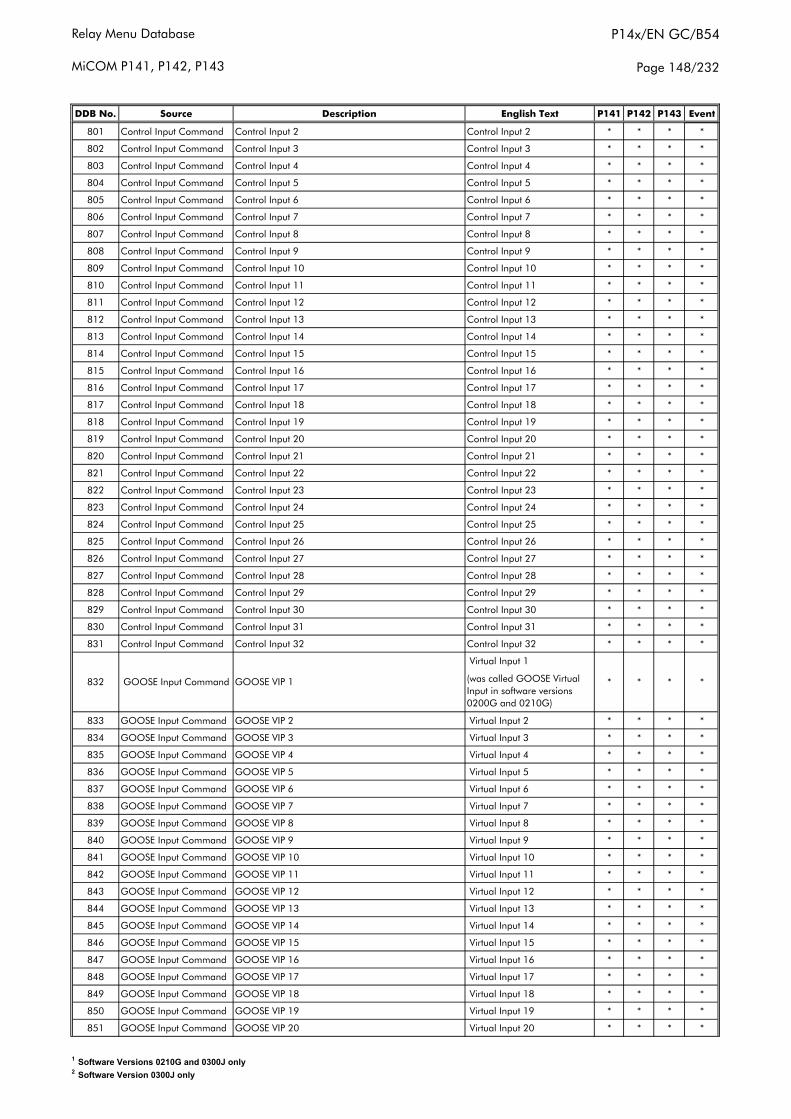
Relay Menu Database
MiCOM P141, P142, P143
P14x/EN GC/B54
Page 148/232
DDB No. Source Description English Text P141 P142 P143 Event
801 Control Input Command Control Input 2 Control Input 2 * * * *
802 Control Input Command Control Input 3 Control Input 3 * * * *
803 Control Input Command Control Input 4 Control Input 4 * * * *
804 Control Input Command Control Input 5 Control Input 5 * * * *
805 Control Input Command Control Input 6 Control Input 6 * * * *
806 Control Input Command Control Input 7 Control Input 7 * * * *
807 Control Input Command Control Input 8 Control Input 8 * * * *
808 Control Input Command Control Input 9 Control Input 9 * * * *
809 Control Input Command Control Input 10 Control Input 10 * * * *
810 Control Input Command Control Input 11 Control Input 11 * * * *
811 Control Input Command Control Input 12 Control Input 12 * * * *
812 Control Input Command Control Input 13 Control Input 13 * * * *
813 Control Input Command Control Input 14 Control Input 14 * * * *
814 Control Input Command Control Input 15 Control Input 15 * * * *
815 Control Input Command Control Input 16 Control Input 16 * * * *
816 Control Input Command Control Input 17 Control Input 17 * * * *
817 Control Input Command Control Input 18 Control Input 18 * * * *
818 Control Input Command Control Input 19 Control Input 19 * * * *
819 Control Input Command Control Input 20 Control Input 20 * * * *
820 Control Input Command Control Input 21 Control Input 21 * * * *
821 Control Input Command Control Input 22 Control Input 22 * * * *
822 Control Input Command Control Input 23 Control Input 23 * * * *
823 Control Input Command Control Input 24 Control Input 24 * * * *
824 Control Input Command Control Input 25 Control Input 25 * * * *
825 Control Input Command Control Input 26 Control Input 26 * * * *
826 Control Input Command Control Input 27 Control Input 27 * * * *
827 Control Input Command Control Input 28 Control Input 28 * * * *
828 Control Input Command Control Input 29 Control Input 29 * * * *
829 Control Input Command Control Input 30 Control Input 30 * * * *
830 Control Input Command Control Input 31 Control Input 31 * * * *
831 Control Input Command Control Input 32 Control Input 32 * * * *
Virtual Input 1
(was called GOOSE Virtual Input in software versions 0200G and 0210G)
833 GOOSE Input Command GOOSE VIP 2 Virtual Input 2 * * * *
834 GOOSE Input Command GOOSE VIP 3 Virtual Input 3 * * * *
835 GOOSE Input Command GOOSE VIP 4 Virtual Input 4 * * * *
836 GOOSE Input Command GOOSE VIP 5 Virtual Input 5 * * * *
837 GOOSE Input Command GOOSE VIP 6 Virtual Input 6 * * * *
838 GOOSE Input Command GOOSE VIP 7 Virtual Input 7 * * * *
839 GOOSE Input Command GOOSE VIP 8 Virtual Input 8 * * * *
840 GOOSE Input Command GOOSE VIP 9 Virtual Input 9 * * * *
841 GOOSE Input Command GOOSE VIP 10 Virtual Input 10 * * * *
842 GOOSE Input Command GOOSE VIP 11 Virtual Input 11 * * * *
843 GOOSE Input Command GOOSE VIP 12 Virtual Input 12 * * * *
844 GOOSE Input Command GOOSE VIP 13 Virtual Input 13 * * * *
845 GOOSE Input Command GOOSE VIP 14 Virtual Input 14 * * * *
846 GOOSE Input Command GOOSE VIP 15 Virtual Input 15 * * * *
847 GOOSE Input Command GOOSE VIP 16 Virtual Input 16 * * * *
848 GOOSE Input Command GOOSE VIP 17 Virtual Input 17 * * * *
849 GOOSE Input Command GOOSE VIP 18 Virtual Input 18 * * * *
850 GOOSE Input Command GOOSE VIP 19 Virtual Input 19 * * * *
851 GOOSE Input Command GOOSE VIP 20 Virtual Input 20 * * * *
832 GOOSE Input Command GOOSE VIP 1 * * * *
1 Software Versions 0210G and 0300J only2 Software Version 0300J only
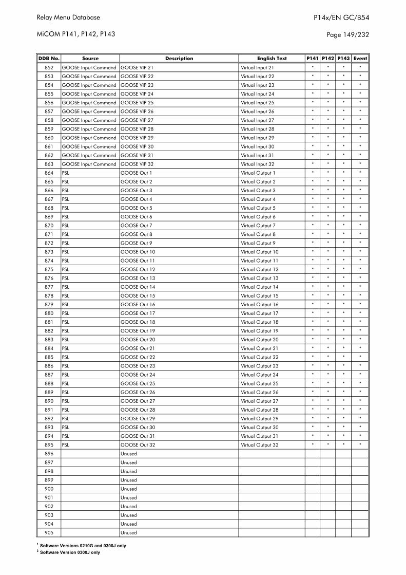
Relay Menu Database
MiCOM P141, P142, P143
P14x/EN GC/B54
Page 149/232
DDB No. Source Description English Text P141 P142 P143 Event
852 GOOSE Input Command GOOSE VIP 21 Virtual Input 21 * * * *
853 GOOSE Input Command GOOSE VIP 22 Virtual Input 22 * * * *
854 GOOSE Input Command GOOSE VIP 23 Virtual Input 23 * * * *
855 GOOSE Input Command GOOSE VIP 24 Virtual Input 24 * * * *
856 GOOSE Input Command GOOSE VIP 25 Virtual Input 25 * * * *
857 GOOSE Input Command GOOSE VIP 26 Virtual Input 26 * * * *
858 GOOSE Input Command GOOSE VIP 27 Virtual Input 27 * * * *
859 GOOSE Input Command GOOSE VIP 28 Virtual Input 28 * * * *
860 GOOSE Input Command GOOSE VIP 29 Virtual Input 29 * * * *
861 GOOSE Input Command GOOSE VIP 30 Virtual Input 30 * * * *
862 GOOSE Input Command GOOSE VIP 31 Virtual Input 31 * * * *
863 GOOSE Input Command GOOSE VIP 32 Virtual Input 32 * * * *
864 PSL GOOSE Out 1 Virtual Output 1 * * * *
865 PSL GOOSE Out 2 Virtual Output 2 * * * *
866 PSL GOOSE Out 3 Virtual Output 3 * * * *
867 PSL GOOSE Out 4 Virtual Output 4 * * * *
868 PSL GOOSE Out 5 Virtual Output 5 * * * *
869 PSL GOOSE Out 6 Virtual Output 6 * * * *
870 PSL GOOSE Out 7 Virtual Output 7 * * * *
871 PSL GOOSE Out 8 Virtual Output 8 * * * *
872 PSL GOOSE Out 9 Virtual Output 9 * * * *
873 PSL GOOSE Out 10 Virtual Output 10 * * * *
874 PSL GOOSE Out 11 Virtual Output 11 * * * *
875 PSL GOOSE Out 12 Virtual Output 12 * * * *
876 PSL GOOSE Out 13 Virtual Output 13 * * * *
877 PSL GOOSE Out 14 Virtual Output 14 * * * *
878 PSL GOOSE Out 15 Virtual Output 15 * * * *
879 PSL GOOSE Out 16 Virtual Output 16 * * * *
880 PSL GOOSE Out 17 Virtual Output 17 * * * *
881 PSL GOOSE Out 18 Virtual Output 18 * * * *
882 PSL GOOSE Out 19 Virtual Output 19 * * * *
883 PSL GOOSE Out 20 Virtual Output 20 * * * *
884 PSL GOOSE Out 21 Virtual Output 21 * * * *
885 PSL GOOSE Out 22 Virtual Output 22 * * * *
886 PSL GOOSE Out 23 Virtual Output 23 * * * *
887 PSL GOOSE Out 24 Virtual Output 24 * * * *
888 PSL GOOSE Out 25 Virtual Output 25 * * * *
889 PSL GOOSE Out 26 Virtual Output 26 * * * *
890 PSL GOOSE Out 27 Virtual Output 27 * * * *
891 PSL GOOSE Out 28 Virtual Output 28 * * * *
892 PSL GOOSE Out 29 Virtual Output 29 * * * *
893 PSL GOOSE Out 30 Virtual Output 30 * * * *
894 PSL GOOSE Out 31 Virtual Output 31 * * * *
895 PSL GOOSE Out 32 Virtual Output 32 * * * *
896 Unused
897 Unused
898 Unused
899 Unused
900 Unused
901 Unused
902 Unused
903 Unused
904 Unused
905 Unused
1 Software Versions 0210G and 0300J only2 Software Version 0300J only
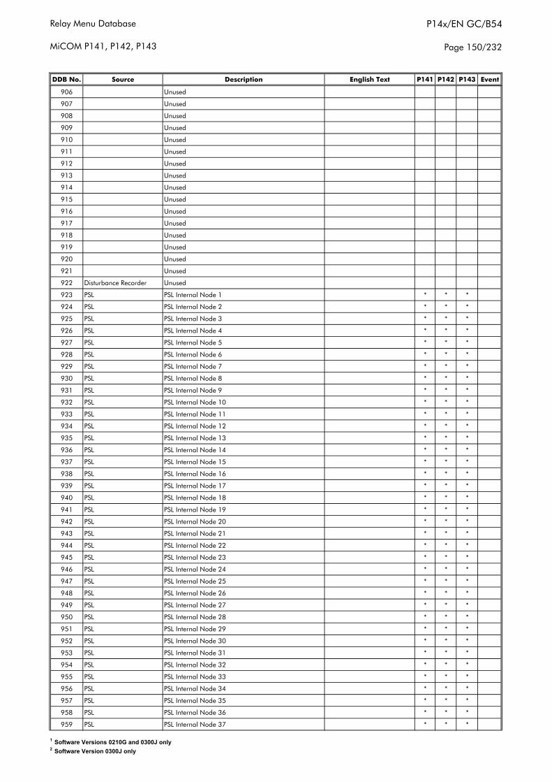
Relay Menu Database
MiCOM P141, P142, P143
P14x/EN GC/B54
Page 150/232
DDB No. Source Description English Text P141 P142 P143 Event
906 Unused
907 Unused
908 Unused
909 Unused
910 Unused
911 Unused
912 Unused
913 Unused
914 Unused
915 Unused
916 Unused
917 Unused
918 Unused
919 Unused
920 Unused
921 Unused
922 Disturbance Recorder Unused
923 PSL PSL Internal Node 1 * * *
924 PSL PSL Internal Node 2 * * *
925 PSL PSL Internal Node 3 * * *
926 PSL PSL Internal Node 4 * * *
927 PSL PSL Internal Node 5 * * *
928 PSL PSL Internal Node 6 * * *
929 PSL PSL Internal Node 7 * * *
930 PSL PSL Internal Node 8 * * *
931 PSL PSL Internal Node 9 * * *
932 PSL PSL Internal Node 10 * * *
933 PSL PSL Internal Node 11 * * *
934 PSL PSL Internal Node 12 * * *
935 PSL PSL Internal Node 13 * * *
936 PSL PSL Internal Node 14 * * *
937 PSL PSL Internal Node 15 * * *
938 PSL PSL Internal Node 16 * * *
939 PSL PSL Internal Node 17 * * *
940 PSL PSL Internal Node 18 * * *
941 PSL PSL Internal Node 19 * * *
942 PSL PSL Internal Node 20 * * *
943 PSL PSL Internal Node 21 * * *
944 PSL PSL Internal Node 22 * * *
945 PSL PSL Internal Node 23 * * *
946 PSL PSL Internal Node 24 * * *
947 PSL PSL Internal Node 25 * * *
948 PSL PSL Internal Node 26 * * *
949 PSL PSL Internal Node 27 * * *
950 PSL PSL Internal Node 28 * * *
951 PSL PSL Internal Node 29 * * *
952 PSL PSL Internal Node 30 * * *
953 PSL PSL Internal Node 31 * * *
954 PSL PSL Internal Node 32 * * *
955 PSL PSL Internal Node 33 * * *
956 PSL PSL Internal Node 34 * * *
957 PSL PSL Internal Node 35 * * *
958 PSL PSL Internal Node 36 * * *
959 PSL PSL Internal Node 37 * * *
1 Software Versions 0210G and 0300J only2 Software Version 0300J only
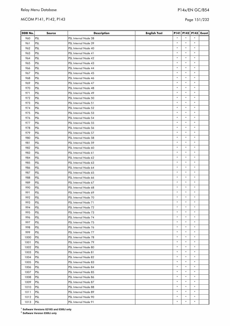
Relay Menu Database
MiCOM P141, P142, P143
P14x/EN GC/B54
Page 151/232
DDB No. Source Description English Text P141 P142 P143 Event
960 PSL PSL Internal Node 38 * * *
961 PSL PSL Internal Node 39 * * *
962 PSL PSL Internal Node 40 * * *
963 PSL PSL Internal Node 41 * * *
964 PSL PSL Internal Node 42 * * *
965 PSL PSL Internal Node 43 * * *
966 PSL PSL Internal Node 44 * * *
967 PSL PSL Internal Node 45 * * *
968 PSL PSL Internal Node 46 * * *
969 PSL PSL Internal Node 47 * * *
970 PSL PSL Internal Node 48 * * *
971 PSL PSL Internal Node 49 * * *
972 PSL PSL Internal Node 50 * * *
973 PSL PSL Internal Node 51 * * *
974 PSL PSL Internal Node 52 * * *
975 PSL PSL Internal Node 53 * * *
976 PSL PSL Internal Node 54 * * *
977 PSL PSL Internal Node 55 * * *
978 PSL PSL Internal Node 56 * * *
979 PSL PSL Internal Node 57 * * *
980 PSL PSL Internal Node 58 * * *
981 PSL PSL Internal Node 59 * * *
982 PSL PSL Internal Node 60 * * *
983 PSL PSL Internal Node 61 * * *
984 PSL PSL Internal Node 62 * * *
985 PSL PSL Internal Node 63 * * *
986 PSL PSL Internal Node 64 * * *
987 PSL PSL Internal Node 65 * * *
988 PSL PSL Internal Node 66 * * *
989 PSL PSL Internal Node 67 * * *
990 PSL PSL Internal Node 68 * * *
991 PSL PSL Internal Node 69 * * *
992 PSL PSL Internal Node 70 * * *
993 PSL PSL Internal Node 71 * * *
994 PSL PSL Internal Node 72 * * *
995 PSL PSL Internal Node 73 * * *
996 PSL PSL Internal Node 74 * * *
997 PSL PSL Internal Node 75 * * *
998 PSL PSL Internal Node 76 * * *
999 PSL PSL Internal Node 77 * * *
1000 PSL PSL Internal Node 78 * * *
1001 PSL PSL Internal Node 79 * * *
1002 PSL PSL Internal Node 80 * * *
1003 PSL PSL Internal Node 81 * * *
1004 PSL PSL Internal Node 82 * * *
1005 PSL PSL Internal Node 83 * * *
1006 PSL PSL Internal Node 84 * * *
1007 PSL PSL Internal Node 85 * * *
1008 PSL PSL Internal Node 86 * * *
1009 PSL PSL Internal Node 87 * * *
1010 PSL PSL Internal Node 88 * * *
1011 PSL PSL Internal Node 89 * * *
1012 PSL PSL Internal Node 90 * * *
1013 PSL PSL Internal Node 91 * * *
1 Software Versions 0210G and 0300J only2 Software Version 0300J only
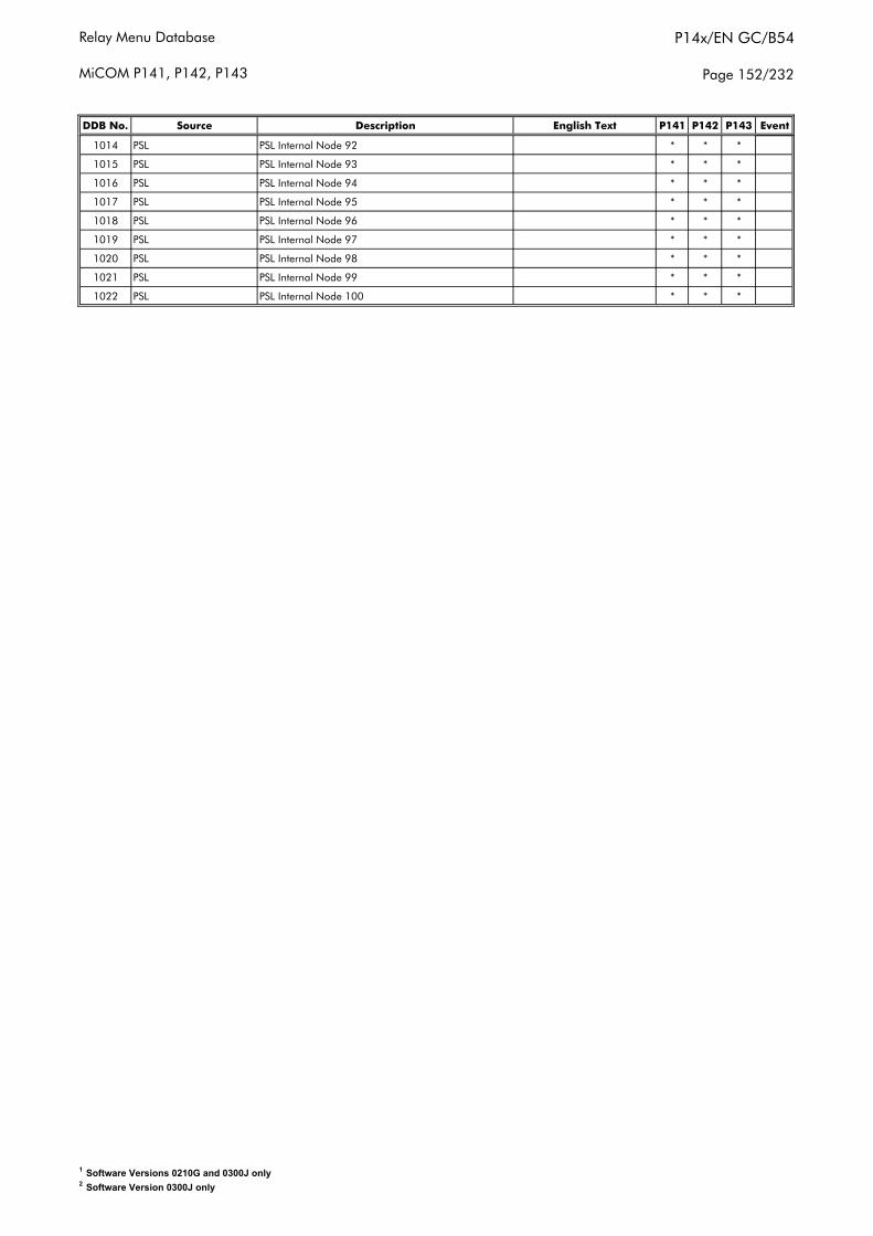
Relay Menu Database
MiCOM P141, P142, P143
P14x/EN GC/B54
Page 152/232
DDB No. Source Description English Text P141 P142 P143 Event
1014 PSL PSL Internal Node 92 * * *
1015 PSL PSL Internal Node 93 * * *
1016 PSL PSL Internal Node 94 * * *
1017 PSL PSL Internal Node 95 * * *
1018 PSL PSL Internal Node 96 * * *
1019 PSL PSL Internal Node 97 * * *
1020 PSL PSL Internal Node 98 * * *
1021 PSL PSL Internal Node 99 * * *
1022 PSL PSL Internal Node 100 * * *
1 Software Versions 0210G and 0300J only2 Software Version 0300J only
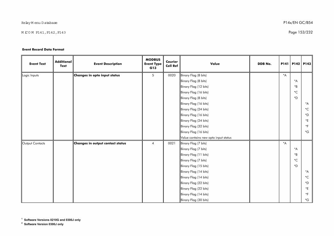
Relay M enu Database
M iCO M P141, P142, P143
P14x/EN GC/B54
Page 153/232
Logic Inputs Changes in opto input status 5 0020 Binary Flag (8 bits) *A
Binary Flag (8 bits) *A
Binary Flag (12 bits) *B
Binary Flag (16 bits) *C
Binary Flag (8 bits) *D
Binary Flag (16 bits) *A
Binary Flag (24 bits) *C
Binary Flag (16 bits) *D
Binary Flag (24 bits) *E
Binary Flag (32 bits) *F
Binary Flag (16 bits) *G
Value contains new opto input status
Output Contacts Changes in output contact status 4 0021 Binary Flag (7 bits) *A
Binary Flag (7 bits) *A
Binary Flag (11 bits) *B
Binary Flag (7 bits) *C
Binary Flag (15 bits) *D
Binary Flag (14 bits) *A
Binary Flag (14 bits) *C
Binary Flag (22 bits) *D
Binary Flag (22 bits) *E
Binary Flag (14 bits) *F
Binary Flag (30 bits) *G
P142 P143Additional
Text
Event Record Data Format
Event Text Event DescriptionMODBUS
Event Type G13
Courier Cell Ref
Value DDB No. P141
1 Software Versions 0210G and 0300J only2 Software Version 0300J only
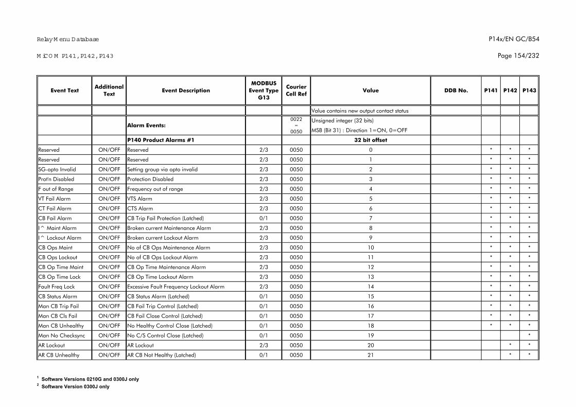
Relay M enu Database
M iCO M P141, P142, P143
P14x/EN GC/B54
Page 154/232
P142 P143Additional
TextEvent Text Event Description
MODBUS Event Type
G13
Courier Cell Ref
Value DDB No. P141
Value contains new output contact status
Unsigned integer (32 bits)
MSB (Bit 31) : Direction 1=ON, 0=OFF
P140 Product Alarms #1 32 bit offset
Reserved ON/OFF Reserved 2/3 0050 0 * * *
Reserved ON/OFF Reserved 2/3 0050 1 * * *
SG-opto Invalid ON/OFF Setting group via opto invalid 2/3 0050 2 * * *
Prot'n Disabled ON/OFF Protection Disabled 2/3 0050 3 * * *
F out of Range ON/OFF Frequency out of range 2/3 0050 4 * * *
VT Fail Alarm ON/OFF VTS Alarm 2/3 0050 5 * * *
CT Fail Alarm ON/OFF CTS Alarm 2/3 0050 6 * * *
CB Fail Alarm ON/OFF CB Trip Fail Protection (Latched) 0/1 0050 7 * * *
I^ Maint Alarm ON/OFF Broken current Maintenance Alarm 2/3 0050 8 * * *
I^ Lockout Alarm ON/OFF Broken current Lockout Alarm 2/3 0050 9 * * *
CB Ops Maint ON/OFF No of CB Ops Maintenance Alarm 2/3 0050 10 * * *
CB Ops Lockout ON/OFF No of CB Ops Lockout Alarm 2/3 0050 11 * * *
CB Op Time Maint ON/OFF CB Op Time Maintenance Alarm 2/3 0050 12 * * *
CB Op Time Lock ON/OFF CB Op Time Lockout Alarm 2/3 0050 13 * * *
Fault Freq Lock ON/OFF Excessive Fault Frequency Lockout Alarm 2/3 0050 14 * * *
CB Status Alarm ON/OFF CB Status Alarm (Latched) 0/1 0050 15 * * *
Man CB Trip Fail ON/OFF CB Fail Trip Control (Latched) 0/1 0050 16 * * *
Man CB Cls Fail ON/OFF CB Fail Close Control (Latched) 0/1 0050 17 * * *
Man CB Unhealthy ON/OFF No Healthy Control Close (Latched) 0/1 0050 18 * * *
Man No Checksync ON/OFF No C/S Control Close (Latched) 0/1 0050 19 *
AR Lockout ON/OFF AR Lockout 2/3 0050 20 * *
AR CB Unhealthy ON/OFF AR CB Not Healthy (Latched) 0/1 0050 21 * *
0022 =
0050Alarm Events:
1 Software Versions 0210G and 0300J only2 Software Version 0300J only
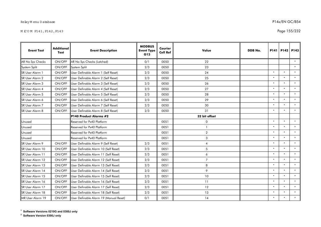
Relay M enu Database
M iCO M P141, P142, P143
P14x/EN GC/B54
Page 155/232
P142 P143Additional
TextEvent Text Event Description
MODBUS Event Type
G13
Courier Cell Ref
Value DDB No. P141
AR No Sys Checks ON/OFF AR No Sys Checks (Latched) 0/1 0050 22 *
System Split ON/OFF System Split 2/3 0050 23 *
SR User Alarm 1 ON/OFF User Definable Alarm 1 (Self Reset) 2/3 0050 24 * * *
SR User Alarm 2 ON/OFF User Definable Alarm 2 (Self Reset) 2/3 0050 25 * * *
SR User Alarm 3 ON/OFF User Definable Alarm 3 (Self Reset) 2/3 0050 26 * * *
SR User Alarm 4 ON/OFF User Definable Alarm 4 (Self Reset) 2/3 0050 27 * * *
SR User Alarm 5 ON/OFF User Definable Alarm 5 (Self Reset) 2/3 0050 28 * * *
SR User Alarm 6 ON/OFF User Definable Alarm 6 (Self Reset) 2/3 0050 29 * * *
SR User Alarm 7 ON/OFF User Definable Alarm 7 (Self Reset) 2/3 0050 30 * * *
SR User Alarm 8 ON/OFF User Definable Alarm 8 (Self Reset) 2/3 0050 31 * * *
P140 Product Alarms #2 32 bit offset
Unused Reserved for Px40 Platform 0051 0 * * *
Unused Reserved for Px40 Platform 0051 1 * * *
Unused Reserved for Px40 Platform 0051 2 * * *
Unused Reserved for Px40 Platform 0051 3 * * *
SR User Alarm 9 ON/OFF User Definable Alarm 9 (Self Reset) 2/3 0051 4 * * *
SR User Alarm 10 ON/OFF User Definable Alarm 10 (Self Reset) 2/3 0051 5 * * *
SR User Alarm 11 ON/OFF User Definable Alarm 11 (Self Reset) 2/3 0051 6 * * *
SR User Alarm 12 ON/OFF User Definable Alarm 12 (Self Reset) 2/3 0051 7 * * *
SR User Alarm 13 ON/OFF User Definable Alarm 13 (Self Reset) 2/3 0051 8 * * *
SR User Alarm 14 ON/OFF User Definable Alarm 14 (Self Reset) 2/3 0051 9 * * *
SR User Alarm 15 ON/OFF User Definable Alarm 15 (Self Reset) 2/3 0051 10 * * *
SR User Alarm 16 ON/OFF User Definable Alarm 16 (Self Reset) 2/3 0051 11 * * *
SR User Alarm 17 ON/OFF User Definable Alarm 17 (Self Reset) 2/3 0051 12 * * *
SR User Alarm 18 ON/OFF User Definable Alarm 18 (Self Reset) 2/3 0051 13 * * *
MR User Alarm 19 ON/OFF User Definable Alarm 19 (Manual Reset) 0/1 0051 14 * * *
1 Software Versions 0210G and 0300J only2 Software Version 0300J only
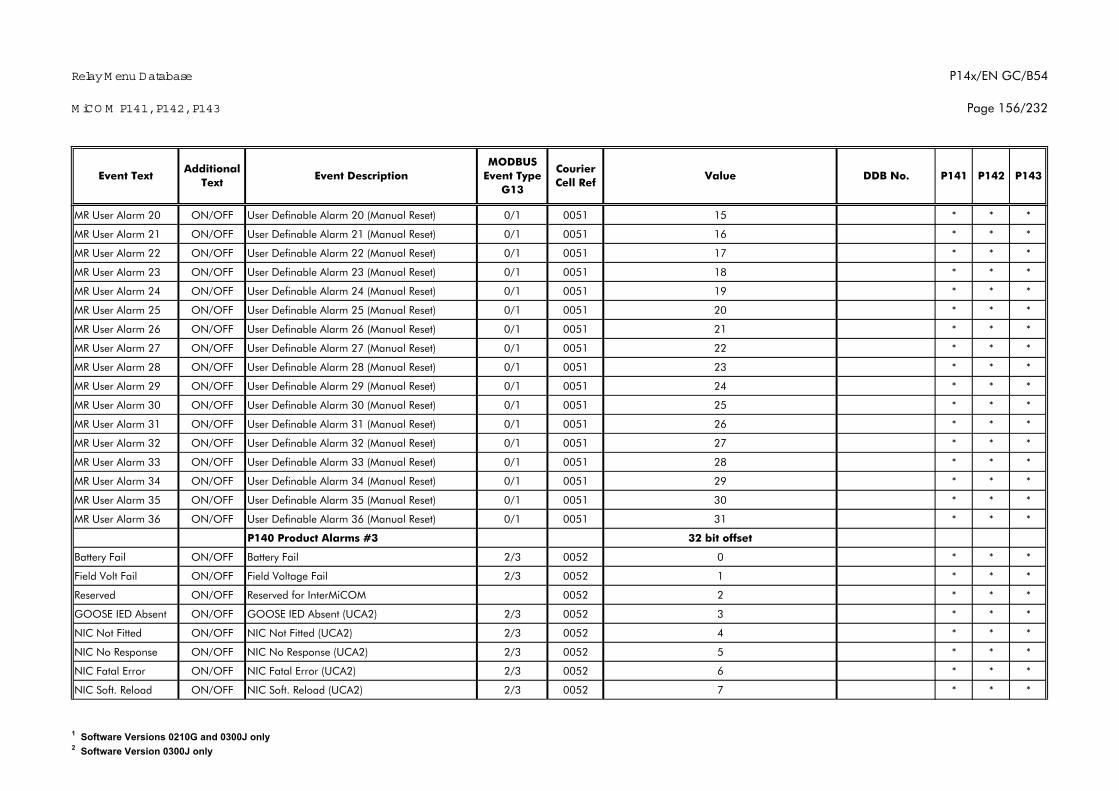
Relay M enu Database
M iCO M P141, P142, P143
P14x/EN GC/B54
Page 156/232
P142 P143Additional
TextEvent Text Event Description
MODBUS Event Type
G13
Courier Cell Ref
Value DDB No. P141
MR User Alarm 20 ON/OFF User Definable Alarm 20 (Manual Reset) 0/1 0051 15 * * *
MR User Alarm 21 ON/OFF User Definable Alarm 21 (Manual Reset) 0/1 0051 16 * * *
MR User Alarm 22 ON/OFF User Definable Alarm 22 (Manual Reset) 0/1 0051 17 * * *
MR User Alarm 23 ON/OFF User Definable Alarm 23 (Manual Reset) 0/1 0051 18 * * *
MR User Alarm 24 ON/OFF User Definable Alarm 24 (Manual Reset) 0/1 0051 19 * * *
MR User Alarm 25 ON/OFF User Definable Alarm 25 (Manual Reset) 0/1 0051 20 * * *
MR User Alarm 26 ON/OFF User Definable Alarm 26 (Manual Reset) 0/1 0051 21 * * *
MR User Alarm 27 ON/OFF User Definable Alarm 27 (Manual Reset) 0/1 0051 22 * * *
MR User Alarm 28 ON/OFF User Definable Alarm 28 (Manual Reset) 0/1 0051 23 * * *
MR User Alarm 29 ON/OFF User Definable Alarm 29 (Manual Reset) 0/1 0051 24 * * *
MR User Alarm 30 ON/OFF User Definable Alarm 30 (Manual Reset) 0/1 0051 25 * * *
MR User Alarm 31 ON/OFF User Definable Alarm 31 (Manual Reset) 0/1 0051 26 * * *
MR User Alarm 32 ON/OFF User Definable Alarm 32 (Manual Reset) 0/1 0051 27 * * *
MR User Alarm 33 ON/OFF User Definable Alarm 33 (Manual Reset) 0/1 0051 28 * * *
MR User Alarm 34 ON/OFF User Definable Alarm 34 (Manual Reset) 0/1 0051 29 * * *
MR User Alarm 35 ON/OFF User Definable Alarm 35 (Manual Reset) 0/1 0051 30 * * *
MR User Alarm 36 ON/OFF User Definable Alarm 36 (Manual Reset) 0/1 0051 31 * * *
P140 Product Alarms #3 32 bit offset
Battery Fail ON/OFF Battery Fail 2/3 0052 0 * * *
Field Volt Fail ON/OFF Field Voltage Fail 2/3 0052 1 * * *
Reserved ON/OFF Reserved for InterMiCOM 0052 2 * * *
GOOSE IED Absent ON/OFF GOOSE IED Absent (UCA2) 2/3 0052 3 * * *
NIC Not Fitted ON/OFF NIC Not Fitted (UCA2) 2/3 0052 4 * * *
NIC No Response ON/OFF NIC No Response (UCA2) 2/3 0052 5 * * *
NIC Fatal Error ON/OFF NIC Fatal Error (UCA2) 2/3 0052 6 * * *
NIC Soft. Reload ON/OFF NIC Soft. Reload (UCA2) 2/3 0052 7 * * *
1 Software Versions 0210G and 0300J only2 Software Version 0300J only
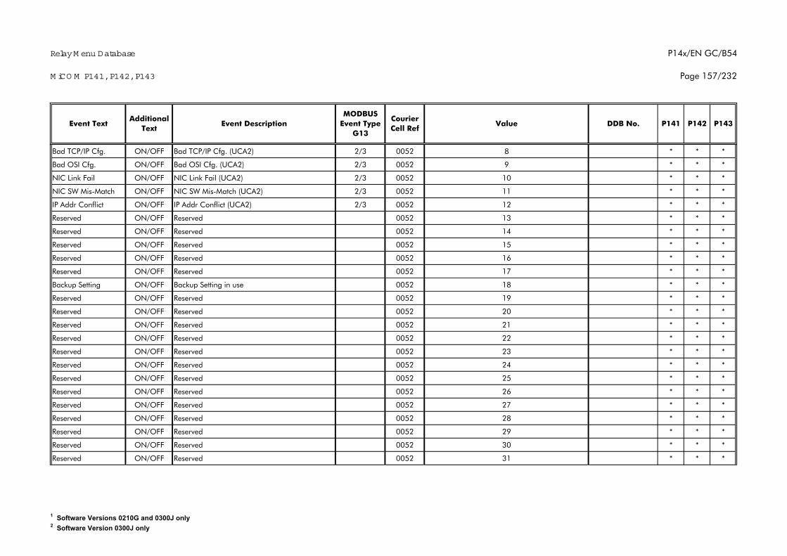
Relay M enu Database
M iCO M P141, P142, P143
P14x/EN GC/B54
Page 157/232
P142 P143Additional
TextEvent Text Event Description
MODBUS Event Type
G13
Courier Cell Ref
Value DDB No. P141
Bad TCP/IP Cfg. ON/OFF Bad TCP/IP Cfg. (UCA2) 2/3 0052 8 * * *
Bad OSI Cfg. ON/OFF Bad OSI Cfg. (UCA2) 2/3 0052 9 * * *
NIC Link Fail ON/OFF NIC Link Fail (UCA2) 2/3 0052 10 * * *
NIC SW Mis-Match ON/OFF NIC SW Mis-Match (UCA2) 2/3 0052 11 * * *
IP Addr Conflict ON/OFF IP Addr Conflict (UCA2) 2/3 0052 12 * * *
Reserved ON/OFF Reserved 0052 13 * * *
Reserved ON/OFF Reserved 0052 14 * * *
Reserved ON/OFF Reserved 0052 15 * * *
Reserved ON/OFF Reserved 0052 16 * * *
Reserved ON/OFF Reserved 0052 17 * * *
Backup Setting ON/OFF Backup Setting in use 0052 18 * * *
Reserved ON/OFF Reserved 0052 19 * * *
Reserved ON/OFF Reserved 0052 20 * * *
Reserved ON/OFF Reserved 0052 21 * * *
Reserved ON/OFF Reserved 0052 22 * * *
Reserved ON/OFF Reserved 0052 23 * * *
Reserved ON/OFF Reserved 0052 24 * * *
Reserved ON/OFF Reserved 0052 25 * * *
Reserved ON/OFF Reserved 0052 26 * * *
Reserved ON/OFF Reserved 0052 27 * * *
Reserved ON/OFF Reserved 0052 28 * * *
Reserved ON/OFF Reserved 0052 29 * * *
Reserved ON/OFF Reserved 0052 30 * * *
Reserved ON/OFF Reserved 0052 31 * * *
1 Software Versions 0210G and 0300J only2 Software Version 0300J only
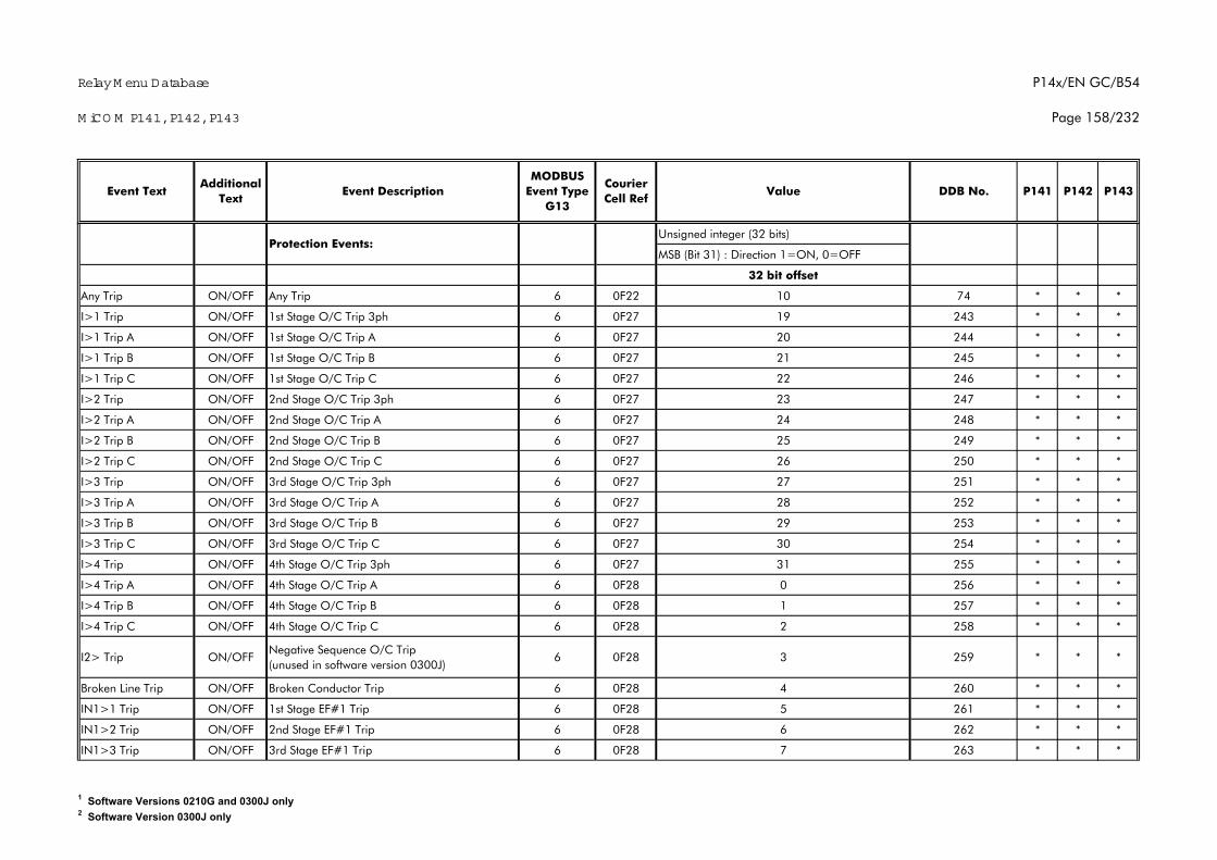
Relay M enu Database
M iCO M P141, P142, P143
P14x/EN GC/B54
Page 158/232
P142 P143Additional
TextEvent Text Event Description
MODBUS Event Type
G13
Courier Cell Ref
Value DDB No. P141
Unsigned integer (32 bits)
MSB (Bit 31) : Direction 1=ON, 0=OFF
32 bit offset
Any Trip ON/OFF Any Trip 6 0F22 10 74 * * *
I>1 Trip ON/OFF 1st Stage O/C Trip 3ph 6 0F27 19 243 * * *
I>1 Trip A ON/OFF 1st Stage O/C Trip A 6 0F27 20 244 * * *
I>1 Trip B ON/OFF 1st Stage O/C Trip B 6 0F27 21 245 * * *
I>1 Trip C ON/OFF 1st Stage O/C Trip C 6 0F27 22 246 * * *
I>2 Trip ON/OFF 2nd Stage O/C Trip 3ph 6 0F27 23 247 * * *
I>2 Trip A ON/OFF 2nd Stage O/C Trip A 6 0F27 24 248 * * *
I>2 Trip B ON/OFF 2nd Stage O/C Trip B 6 0F27 25 249 * * *
I>2 Trip C ON/OFF 2nd Stage O/C Trip C 6 0F27 26 250 * * *
I>3 Trip ON/OFF 3rd Stage O/C Trip 3ph 6 0F27 27 251 * * *
I>3 Trip A ON/OFF 3rd Stage O/C Trip A 6 0F27 28 252 * * *
I>3 Trip B ON/OFF 3rd Stage O/C Trip B 6 0F27 29 253 * * *
I>3 Trip C ON/OFF 3rd Stage O/C Trip C 6 0F27 30 254 * * *
I>4 Trip ON/OFF 4th Stage O/C Trip 3ph 6 0F27 31 255 * * *
I>4 Trip A ON/OFF 4th Stage O/C Trip A 6 0F28 0 256 * * *
I>4 Trip B ON/OFF 4th Stage O/C Trip B 6 0F28 1 257 * * *
I>4 Trip C ON/OFF 4th Stage O/C Trip C 6 0F28 2 258 * * *
I2> Trip ON/OFFNegative Sequence O/C Trip (unused in software version 0300J)
6 0F28 3 259 * * *
Broken Line Trip ON/OFF Broken Conductor Trip 6 0F28 4 260 * * *
IN1>1 Trip ON/OFF 1st Stage EF#1 Trip 6 0F28 5 261 * * *
IN1>2 Trip ON/OFF 2nd Stage EF#1 Trip 6 0F28 6 262 * * *
IN1>3 Trip ON/OFF 3rd Stage EF#1 Trip 6 0F28 7 263 * * *
Protection Events:
1 Software Versions 0210G and 0300J only2 Software Version 0300J only
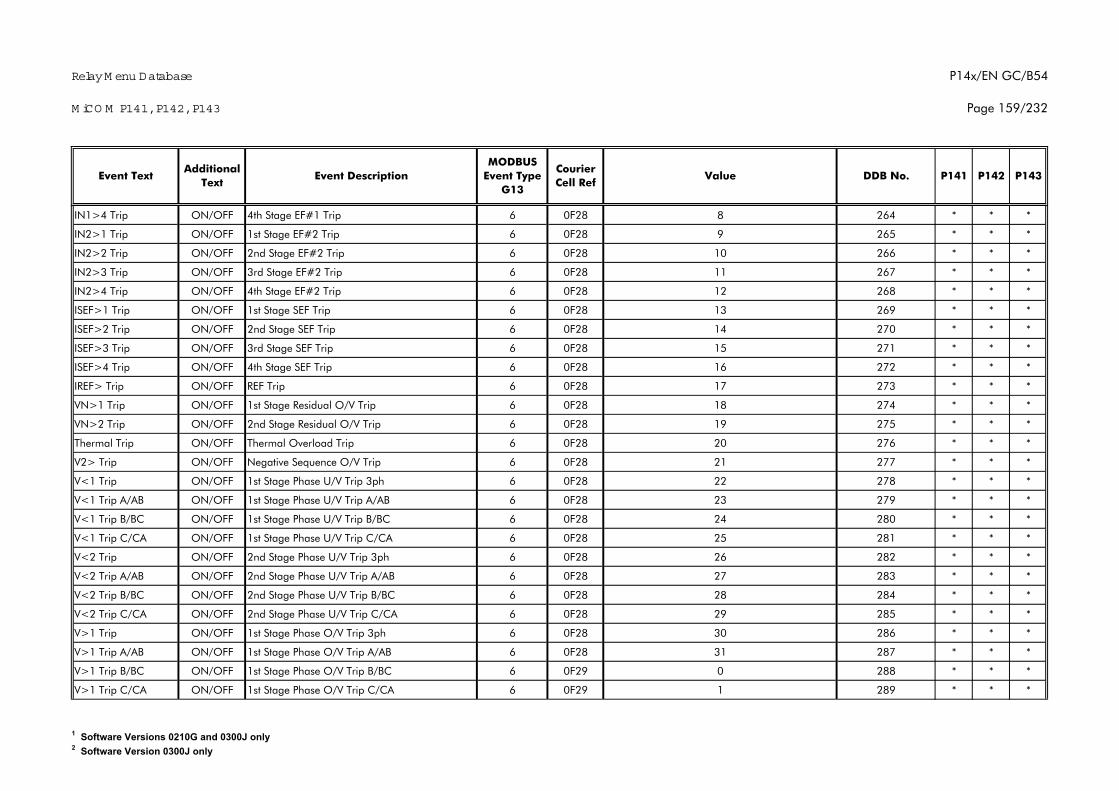
Relay M enu Database
M iCO M P141, P142, P143
P14x/EN GC/B54
Page 159/232
P142 P143Additional
TextEvent Text Event Description
MODBUS Event Type
G13
Courier Cell Ref
Value DDB No. P141
IN1>4 Trip ON/OFF 4th Stage EF#1 Trip 6 0F28 8 264 * * *
IN2>1 Trip ON/OFF 1st Stage EF#2 Trip 6 0F28 9 265 * * *
IN2>2 Trip ON/OFF 2nd Stage EF#2 Trip 6 0F28 10 266 * * *
IN2>3 Trip ON/OFF 3rd Stage EF#2 Trip 6 0F28 11 267 * * *
IN2>4 Trip ON/OFF 4th Stage EF#2 Trip 6 0F28 12 268 * * *
ISEF>1 Trip ON/OFF 1st Stage SEF Trip 6 0F28 13 269 * * *
ISEF>2 Trip ON/OFF 2nd Stage SEF Trip 6 0F28 14 270 * * *
ISEF>3 Trip ON/OFF 3rd Stage SEF Trip 6 0F28 15 271 * * *
ISEF>4 Trip ON/OFF 4th Stage SEF Trip 6 0F28 16 272 * * *
IREF> Trip ON/OFF REF Trip 6 0F28 17 273 * * *
VN>1 Trip ON/OFF 1st Stage Residual O/V Trip 6 0F28 18 274 * * *
VN>2 Trip ON/OFF 2nd Stage Residual O/V Trip 6 0F28 19 275 * * *
Thermal Trip ON/OFF Thermal Overload Trip 6 0F28 20 276 * * *
V2> Trip ON/OFF Negative Sequence O/V Trip 6 0F28 21 277 * * *
V<1 Trip ON/OFF 1st Stage Phase U/V Trip 3ph 6 0F28 22 278 * * *
V<1 Trip A/AB ON/OFF 1st Stage Phase U/V Trip A/AB 6 0F28 23 279 * * *
V<1 Trip B/BC ON/OFF 1st Stage Phase U/V Trip B/BC 6 0F28 24 280 * * *
V<1 Trip C/CA ON/OFF 1st Stage Phase U/V Trip C/CA 6 0F28 25 281 * * *
V<2 Trip ON/OFF 2nd Stage Phase U/V Trip 3ph 6 0F28 26 282 * * *
V<2 Trip A/AB ON/OFF 2nd Stage Phase U/V Trip A/AB 6 0F28 27 283 * * *
V<2 Trip B/BC ON/OFF 2nd Stage Phase U/V Trip B/BC 6 0F28 28 284 * * *
V<2 Trip C/CA ON/OFF 2nd Stage Phase U/V Trip C/CA 6 0F28 29 285 * * *
V>1 Trip ON/OFF 1st Stage Phase O/V Trip 3ph 6 0F28 30 286 * * *
V>1 Trip A/AB ON/OFF 1st Stage Phase O/V Trip A/AB 6 0F28 31 287 * * *
V>1 Trip B/BC ON/OFF 1st Stage Phase O/V Trip B/BC 6 0F29 0 288 * * *
V>1 Trip C/CA ON/OFF 1st Stage Phase O/V Trip C/CA 6 0F29 1 289 * * *
1 Software Versions 0210G and 0300J only2 Software Version 0300J only
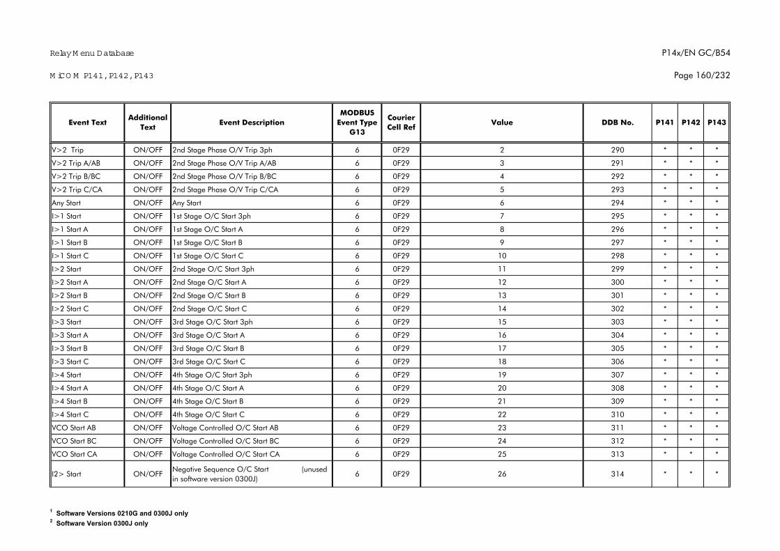
Relay M enu Database
M iCO M P141, P142, P143
P14x/EN GC/B54
Page 160/232
P142 P143Additional
TextEvent Text Event Description
MODBUS Event Type
G13
Courier Cell Ref
Value DDB No. P141
V>2 Trip ON/OFF 2nd Stage Phase O/V Trip 3ph 6 0F29 2 290 * * *
V>2 Trip A/AB ON/OFF 2nd Stage Phase O/V Trip A/AB 6 0F29 3 291 * * *
V>2 Trip B/BC ON/OFF 2nd Stage Phase O/V Trip B/BC 6 0F29 4 292 * * *
V>2 Trip C/CA ON/OFF 2nd Stage Phase O/V Trip C/CA 6 0F29 5 293 * * *
Any Start ON/OFF Any Start 6 0F29 6 294 * * *
I>1 Start ON/OFF 1st Stage O/C Start 3ph 6 0F29 7 295 * * *
I>1 Start A ON/OFF 1st Stage O/C Start A 6 0F29 8 296 * * *
I>1 Start B ON/OFF 1st Stage O/C Start B 6 0F29 9 297 * * *
I>1 Start C ON/OFF 1st Stage O/C Start C 6 0F29 10 298 * * *
I>2 Start ON/OFF 2nd Stage O/C Start 3ph 6 0F29 11 299 * * *
I>2 Start A ON/OFF 2nd Stage O/C Start A 6 0F29 12 300 * * *
I>2 Start B ON/OFF 2nd Stage O/C Start B 6 0F29 13 301 * * *
I>2 Start C ON/OFF 2nd Stage O/C Start C 6 0F29 14 302 * * *
I>3 Start ON/OFF 3rd Stage O/C Start 3ph 6 0F29 15 303 * * *
I>3 Start A ON/OFF 3rd Stage O/C Start A 6 0F29 16 304 * * *
I>3 Start B ON/OFF 3rd Stage O/C Start B 6 0F29 17 305 * * *
I>3 Start C ON/OFF 3rd Stage O/C Start C 6 0F29 18 306 * * *
I>4 Start ON/OFF 4th Stage O/C Start 3ph 6 0F29 19 307 * * *
I>4 Start A ON/OFF 4th Stage O/C Start A 6 0F29 20 308 * * *
I>4 Start B ON/OFF 4th Stage O/C Start B 6 0F29 21 309 * * *
I>4 Start C ON/OFF 4th Stage O/C Start C 6 0F29 22 310 * * *
VCO Start AB ON/OFF Voltage Controlled O/C Start AB 6 0F29 23 311 * * *
VCO Start BC ON/OFF Voltage Controlled O/C Start BC 6 0F29 24 312 * * *
VCO Start CA ON/OFF Voltage Controlled O/C Start CA 6 0F29 25 313 * * *
I2> Start ON/OFFNegative Sequence O/C Start (unused in software version 0300J)
6 0F29 26 314 * * *
1 Software Versions 0210G and 0300J only2 Software Version 0300J only
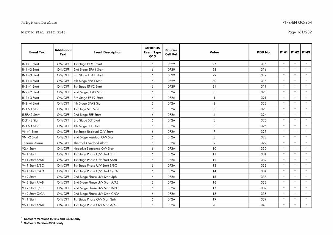
Relay M enu Database
M iCO M P141, P142, P143
P14x/EN GC/B54
Page 161/232
P142 P143Additional
TextEvent Text Event Description
MODBUS Event Type
G13
Courier Cell Ref
Value DDB No. P141
IN1>1 Start ON/OFF 1st Stage EF#1 Start 6 0F29 27 315 * * *
IN1>2 Start ON/OFF 2nd Stage EF#1 Start 6 0F29 28 316 * * *
IN1>3 Start ON/OFF 3rd Stage EF#1 Start 6 0F29 29 317 * * *
IN1>4 Start ON/OFF 4th Stage EF#1 Start 6 0F29 30 318 * * *
IN2>1 Start ON/OFF 1st Stage EF#2 Start 6 0F29 31 319 * * *
IN2>2 Start ON/OFF 2nd Stage EF#2 Start 6 0F2A 0 320 * * *
IN2>3 Start ON/OFF 3rd Stage EF#2 Start 6 0F2A 1 321 * * *
IN2>4 Start ON/OFF 4th Stage EF#2 Start 6 0F2A 2 322 * * *
ISEF>1 Start ON/OFF 1st Stage SEF Start 6 0F2A 3 323 * * *
ISEF>2 Start ON/OFF 2nd Stage SEF Start 6 0F2A 4 324 * * *
ISEF>3 Start ON/OFF 3rd Stage SEF Start 6 0F2A 5 325 * * *
ISEF>4 Start ON/OFF 4th Stage SEF Start 6 0F2A 6 326 * * *
VN>1 Start ON/OFF 1st Stage Residual O/V Start 6 0F2A 7 327 * * *
VN>2 Start ON/OFF 2nd Stage Residual O/V Start 6 0F2A 8 328 * * *
Thermal Alarm ON/OFF Thermal Overload Alarm 6 0F2A 9 329 * * *
V2> Start ON/OFF Negative Sequence O/V Start 6 0F2A 10 330 * * *
V<1 Start ON/OFF 1st Stage Phase U/V Start 3ph 6 0F2A 11 331 * * *
V<1 Start A/AB ON/OFF 1st Stage Phase U/V Start A/AB 6 0F2A 12 332 * * *
V<1 Start B/BC ON/OFF 1st Stage Phase U/V Start B/BC 6 0F2A 13 333 * * *
V<1 Start C/CA ON/OFF 1st Stage Phase U/V Start C/CA 6 0F2A 14 334 * * *
V<2 Start ON/OFF 2nd Stage Phase U/V Start 3ph 6 0F2A 15 335 * * *
V<2 Start A/AB ON/OFF 2nd Stage Phase U/V Start A/AB 6 0F2A 16 336 * * *
V<2 Start B/BC ON/OFF 2nd Stage Phase U/V Start B/BC 6 0F2A 17 337 * * *
V<2 Start C/CA ON/OFF 2nd Stage Phase U/V Start C/CA 6 0F2A 18 338 * * *
V>1 Start ON/OFF 1st Stage Phase O/V Start 3ph 6 0F2A 19 339 * * *
V>1 Start A/AB ON/OFF 1st Stage Phase O/V Start A/AB 6 0F2A 20 340 * * *
1 Software Versions 0210G and 0300J only2 Software Version 0300J only
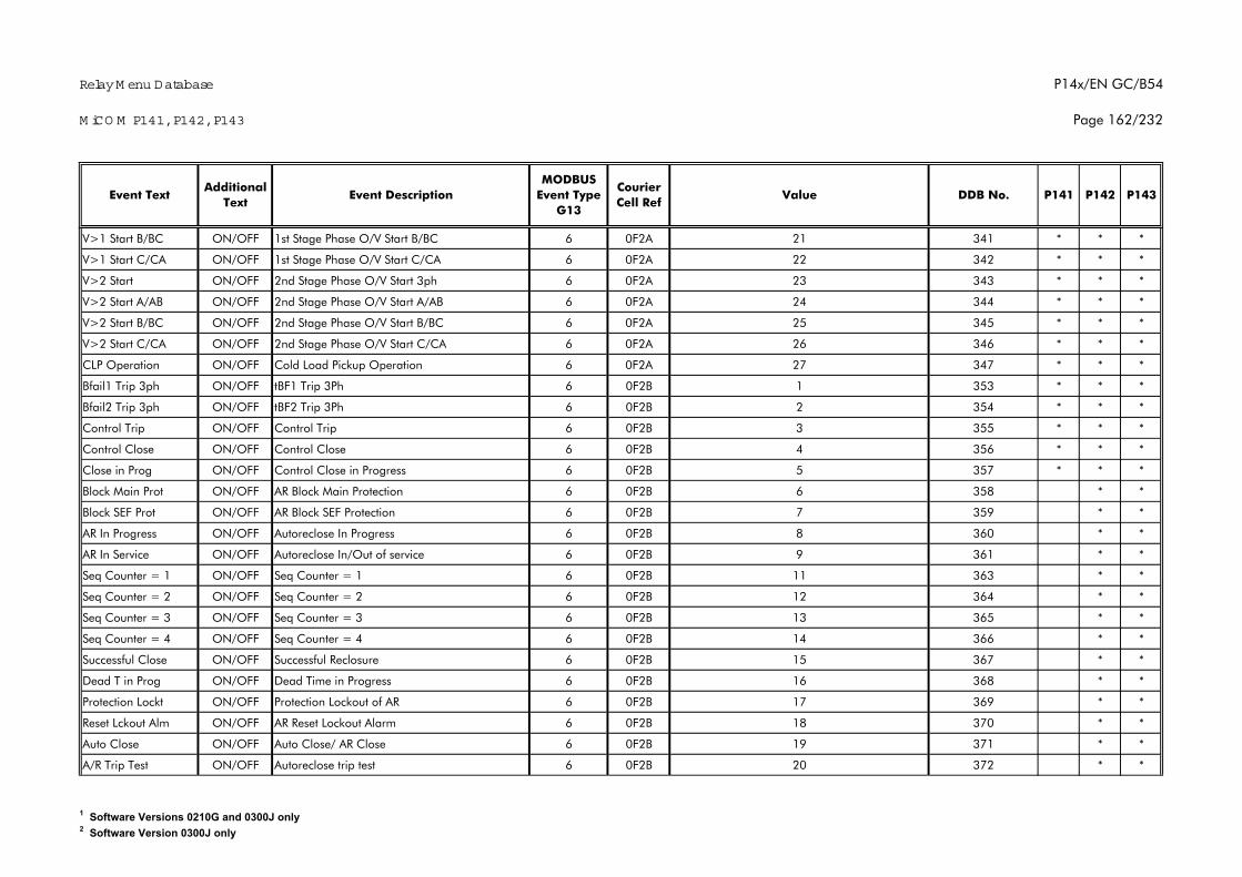
Relay M enu Database
M iCO M P141, P142, P143
P14x/EN GC/B54
Page 162/232
P142 P143Additional
TextEvent Text Event Description
MODBUS Event Type
G13
Courier Cell Ref
Value DDB No. P141
V>1 Start B/BC ON/OFF 1st Stage Phase O/V Start B/BC 6 0F2A 21 341 * * *
V>1 Start C/CA ON/OFF 1st Stage Phase O/V Start C/CA 6 0F2A 22 342 * * *
V>2 Start ON/OFF 2nd Stage Phase O/V Start 3ph 6 0F2A 23 343 * * *
V>2 Start A/AB ON/OFF 2nd Stage Phase O/V Start A/AB 6 0F2A 24 344 * * *
V>2 Start B/BC ON/OFF 2nd Stage Phase O/V Start B/BC 6 0F2A 25 345 * * *
V>2 Start C/CA ON/OFF 2nd Stage Phase O/V Start C/CA 6 0F2A 26 346 * * *
CLP Operation ON/OFF Cold Load Pickup Operation 6 0F2A 27 347 * * *
Bfail1 Trip 3ph ON/OFF tBF1 Trip 3Ph 6 0F2B 1 353 * * *
Bfail2 Trip 3ph ON/OFF tBF2 Trip 3Ph 6 0F2B 2 354 * * *
Control Trip ON/OFF Control Trip 6 0F2B 3 355 * * *
Control Close ON/OFF Control Close 6 0F2B 4 356 * * *
Close in Prog ON/OFF Control Close in Progress 6 0F2B 5 357 * * *
Block Main Prot ON/OFF AR Block Main Protection 6 0F2B 6 358 * *
Block SEF Prot ON/OFF AR Block SEF Protection 6 0F2B 7 359 * *
AR In Progress ON/OFF Autoreclose In Progress 6 0F2B 8 360 * *
AR In Service ON/OFF Autoreclose In/Out of service 6 0F2B 9 361 * *
Seq Counter = 1 ON/OFF Seq Counter = 1 6 0F2B 11 363 * *
Seq Counter = 2 ON/OFF Seq Counter = 2 6 0F2B 12 364 * *
Seq Counter = 3 ON/OFF Seq Counter = 3 6 0F2B 13 365 * *
Seq Counter = 4 ON/OFF Seq Counter = 4 6 0F2B 14 366 * *
Successful Close ON/OFF Successful Reclosure 6 0F2B 15 367 * *
Dead T in Prog ON/OFF Dead Time in Progress 6 0F2B 16 368 * *
Protection Lockt ON/OFF Protection Lockout of AR 6 0F2B 17 369 * *
Reset Lckout Alm ON/OFF AR Reset Lockout Alarm 6 0F2B 18 370 * *
Auto Close ON/OFF Auto Close/ AR Close 6 0F2B 19 371 * *
A/R Trip Test ON/OFF Autoreclose trip test 6 0F2B 20 372 * *
1 Software Versions 0210G and 0300J only2 Software Version 0300J only
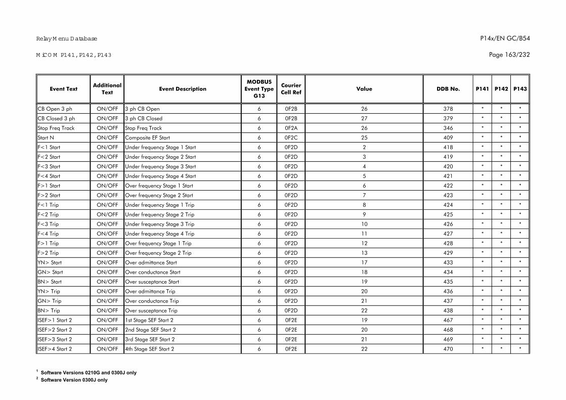
Relay M enu Database
M iCO M P141, P142, P143
P14x/EN GC/B54
Page 163/232
P142 P143Additional
TextEvent Text Event Description
MODBUS Event Type
G13
Courier Cell Ref
Value DDB No. P141
CB Open 3 ph ON/OFF 3 ph CB Open 6 0F2B 26 378 * * *
CB Closed 3 ph ON/OFF 3 ph CB Closed 6 0F2B 27 379 * * *
Stop Freq Track ON/OFF Stop Freq Track 6 0F2A 26 346 * * *
Start N ON/OFF Composite EF Start 6 0F2C 25 409 * * *
F<1 Start ON/OFF Under frequency Stage 1 Start 6 0F2D 2 418 * * *
F<2 Start ON/OFF Under frequency Stage 2 Start 6 0F2D 3 419 * * *
F<3 Start ON/OFF Under frequency Stage 3 Start 6 0F2D 4 420 * * *
F<4 Start ON/OFF Under frequency Stage 4 Start 6 0F2D 5 421 * * *
F>1 Start ON/OFF Over frequency Stage 1 Start 6 0F2D 6 422 * * *
F>2 Start ON/OFF Over frequency Stage 2 Start 6 0F2D 7 423 * * *
F<1 Trip ON/OFF Under frequency Stage 1 Trip 6 0F2D 8 424 * * *
F<2 Trip ON/OFF Under frequency Stage 2 Trip 6 0F2D 9 425 * * *
F<3 Trip ON/OFF Under frequency Stage 3 Trip 6 0F2D 10 426 * * *
F<4 Trip ON/OFF Under frequency Stage 4 Trip 6 0F2D 11 427 * * *
F>1 Trip ON/OFF Over frequency Stage 1 Trip 6 0F2D 12 428 * * *
F>2 Trip ON/OFF Over frequency Stage 2 Trip 6 0F2D 13 429 * * *
YN> Start ON/OFF Over admittance Start 6 0F2D 17 433 * * *
GN> Start ON/OFF Over conductance Start 6 0F2D 18 434 * * *
BN> Start ON/OFF Over susceptance Start 6 0F2D 19 435 * * *
YN> Trip ON/OFF Over admittance Trip 6 0F2D 20 436 * * *
GN> Trip ON/OFF Over conductance Trip 6 0F2D 21 437 * * *
BN> Trip ON/OFF Over susceptance Trip 6 0F2D 22 438 * * *
ISEF>1 Start 2 ON/OFF 1st Stage SEF Start 2 6 0F2E 19 467 * * *
ISEF>2 Start 2 ON/OFF 2nd Stage SEF Start 2 6 0F2E 20 468 * * *
ISEF>3 Start 2 ON/OFF 3rd Stage SEF Start 2 6 0F2E 21 469 * * *
ISEF>4 Start 2 ON/OFF 4th Stage SEF Start 2 6 0F2E 22 470 * * *
1 Software Versions 0210G and 0300J only2 Software Version 0300J only

Relay M enu Database
M iCO M P141, P142, P143
P14x/EN GC/B54
Page 164/232
P142 P143Additional
TextEvent Text Event Description
MODBUS Event Type
G13
Courier Cell Ref
Value DDB No. P141
CS1 Slipfreq> ON/OFF Check Synch 1 Slip > Setting 6 0F2E 23 471 *
CS2 Slipfreq> ON/OFF Check Synch 2 Slip > Setting 6 0F2E 25 473 *
Time Synch ON/OFF Perform time synch via Opto input 6 0F2E 26 474 * * *
df/dt>1 Start ON/OFF 1st Stage df/dt Start 2 6 0F2F 1 481 * * *
df/dt>2 Start ON/OFF 2nd Stage df/dt Start 2 6 0F2F 2 482 * * *
df/dt>3 Start ON/OFF 3rd Stage df/dt Start 2 6 0F2F 3 483 * * *
df/dt>4 Start ON/OFF 4th Stage df/dt Start 2 6 0F2F 4 484 * * *
df/dt>1 Trip ON/OFF 1st Stage df/dt Trip 2 6 0F2F 5 485 * * *
df/dt>2 Trip ON/OFF 2nd Stage df/dt Trip 2 6 0F2F 6 486 * * *
df/dt>3 Trip ON/OFF 3rd Stage df/dt Trip 2 6 0F2F 7 487 * * *
df/dt>4 Trip ON/OFF 4th Stage df/dt Trip 2 6 0F2F 8 488 * * *
I2>1 Start ON/OFF 1st Stage I2> Start 2 6 0F2F 29 509 * * *
I2>2 Start ON/OFF 2nd Stage I2> Start 2 6 0F2F 30 510 * * *
I2>3 Start ON/OFF 3rd Stage I2> Start 2 6 0F2F 31 511 * * *
I2>4 Start ON/OFF 4th Stage I2> Start 2 6 0F30 0 512 * * *
I2>1 Trip ON/OFF 1st Stage I2> Trip 2 6 0F30 1 513 * * *
I2>2 Trip ON/OFF 2nd Stage I2> Trip 2 6 0F30 2 514 * * *
I2>3 Trip ON/OFF 3rd Stage I2> Trip 2 6 0F30 3 515 * * *
I2>4 Trip ON/OFF 4th Stage I2> Trip 2 6 0F30 4 516 * * *
Control Input 1 ON/OFF Control Input 1 6 0F39 0 800 * * *
Control Input 2 ON/OFF Control Input 2 6 0F39 1 801 * * *
Control Input 3 ON/OFF Control Input 3 6 0F39 2 802 * * *
Control Input 4 ON/OFF Control Input 4 6 0F39 3 803 * * *
Control Input 5 ON/OFF Control Input 5 6 0F39 4 804 * * *
Control Input 6 ON/OFF Control Input 6 6 0F39 5 805 * * *
Control Input 7 ON/OFF Control Input 7 6 0F39 6 806 * * *
1 Software Versions 0210G and 0300J only2 Software Version 0300J only
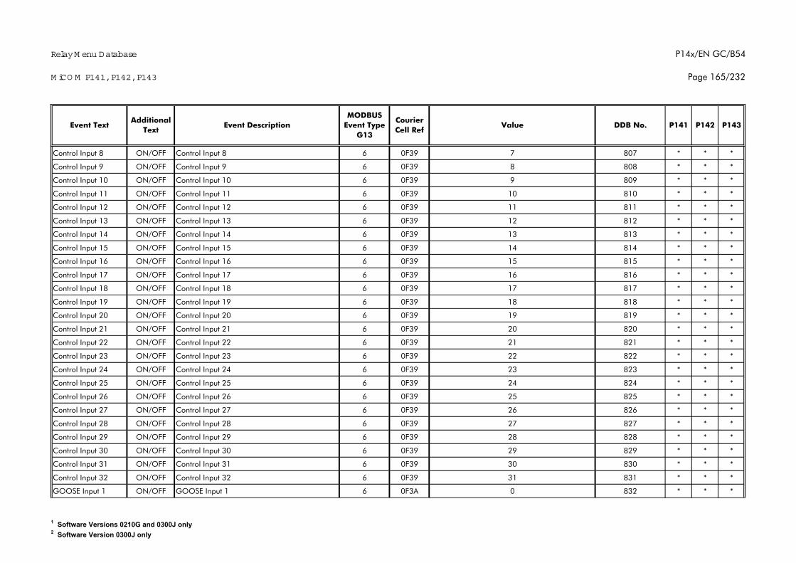
Relay M enu Database
M iCO M P141, P142, P143
P14x/EN GC/B54
Page 165/232
P142 P143Additional
TextEvent Text Event Description
MODBUS Event Type
G13
Courier Cell Ref
Value DDB No. P141
Control Input 8 ON/OFF Control Input 8 6 0F39 7 807 * * *
Control Input 9 ON/OFF Control Input 9 6 0F39 8 808 * * *
Control Input 10 ON/OFF Control Input 10 6 0F39 9 809 * * *
Control Input 11 ON/OFF Control Input 11 6 0F39 10 810 * * *
Control Input 12 ON/OFF Control Input 12 6 0F39 11 811 * * *
Control Input 13 ON/OFF Control Input 13 6 0F39 12 812 * * *
Control Input 14 ON/OFF Control Input 14 6 0F39 13 813 * * *
Control Input 15 ON/OFF Control Input 15 6 0F39 14 814 * * *
Control Input 16 ON/OFF Control Input 16 6 0F39 15 815 * * *
Control Input 17 ON/OFF Control Input 17 6 0F39 16 816 * * *
Control Input 18 ON/OFF Control Input 18 6 0F39 17 817 * * *
Control Input 19 ON/OFF Control Input 19 6 0F39 18 818 * * *
Control Input 20 ON/OFF Control Input 20 6 0F39 19 819 * * *
Control Input 21 ON/OFF Control Input 21 6 0F39 20 820 * * *
Control Input 22 ON/OFF Control Input 22 6 0F39 21 821 * * *
Control Input 23 ON/OFF Control Input 23 6 0F39 22 822 * * *
Control Input 24 ON/OFF Control Input 24 6 0F39 23 823 * * *
Control Input 25 ON/OFF Control Input 25 6 0F39 24 824 * * *
Control Input 26 ON/OFF Control Input 26 6 0F39 25 825 * * *
Control Input 27 ON/OFF Control Input 27 6 0F39 26 826 * * *
Control Input 28 ON/OFF Control Input 28 6 0F39 27 827 * * *
Control Input 29 ON/OFF Control Input 29 6 0F39 28 828 * * *
Control Input 30 ON/OFF Control Input 30 6 0F39 29 829 * * *
Control Input 31 ON/OFF Control Input 31 6 0F39 30 830 * * *
Control Input 32 ON/OFF Control Input 32 6 0F39 31 831 * * *
GOOSE Input 1 ON/OFF GOOSE Input 1 6 0F3A 0 832 * * *
1 Software Versions 0210G and 0300J only2 Software Version 0300J only
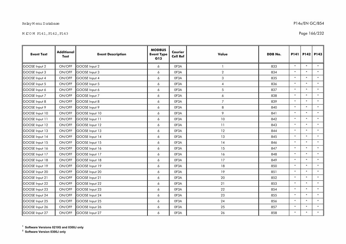
Relay M enu Database
M iCO M P141, P142, P143
P14x/EN GC/B54
Page 166/232
P142 P143Additional
TextEvent Text Event Description
MODBUS Event Type
G13
Courier Cell Ref
Value DDB No. P141
GOOSE Input 2 ON/OFF GOOSE Input 2 6 0F3A 1 833 * * *
GOOSE Input 3 ON/OFF GOOSE Input 3 6 0F3A 2 834 * * *
GOOSE Input 4 ON/OFF GOOSE Input 4 6 0F3A 3 835 * * *
GOOSE Input 5 ON/OFF GOOSE Input 5 6 0F3A 4 836 * * *
GOOSE Input 6 ON/OFF GOOSE Input 6 6 0F3A 5 837 * * *
GOOSE Input 7 ON/OFF GOOSE Input 7 6 0F3A 6 838 * * *
GOOSE Input 8 ON/OFF GOOSE Input 8 6 0F3A 7 839 * * *
GOOSE Input 9 ON/OFF GOOSE Input 9 6 0F3A 8 840 * * *
GOOSE Input 10 ON/OFF GOOSE Input 10 6 0F3A 9 841 * * *
GOOSE Input 11 ON/OFF GOOSE Input 11 6 0F3A 10 842 * * *
GOOSE Input 12 ON/OFF GOOSE Input 12 6 0F3A 11 843 * * *
GOOSE Input 13 ON/OFF GOOSE Input 13 6 0F3A 12 844 * * *
GOOSE Input 14 ON/OFF GOOSE Input 14 6 0F3A 13 845 * * *
GOOSE Input 15 ON/OFF GOOSE Input 15 6 0F3A 14 846 * * *
GOOSE Input 16 ON/OFF GOOSE Input 16 6 0F3A 15 847 * * *
GOOSE Input 17 ON/OFF GOOSE Input 17 6 0F3A 16 848 * * *
GOOSE Input 18 ON/OFF GOOSE Input 18 6 0F3A 17 849 * * *
GOOSE Input 19 ON/OFF GOOSE Input 19 6 0F3A 18 850 * * *
GOOSE Input 20 ON/OFF GOOSE Input 20 6 0F3A 19 851 * * *
GOOSE Input 21 ON/OFF GOOSE Input 21 6 0F3A 20 852 * * *
GOOSE Input 22 ON/OFF GOOSE Input 22 6 0F3A 21 853 * * *
GOOSE Input 23 ON/OFF GOOSE Input 23 6 0F3A 22 854 * * *
GOOSE Input 24 ON/OFF GOOSE Input 24 6 0F3A 23 855 * * *
GOOSE Input 25 ON/OFF GOOSE Input 25 6 0F3A 24 856 * * *
GOOSE Input 26 ON/OFF GOOSE Input 26 6 0F3A 25 857 * * *
GOOSE Input 27 ON/OFF GOOSE Input 27 6 0F3A 26 858 * * *
1 Software Versions 0210G and 0300J only2 Software Version 0300J only
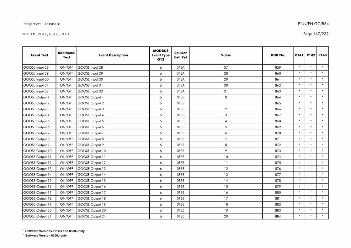
Relay M enu Database
M iCO M P141, P142, P143
P14x/EN GC/B54
Page 167/232
P142 P143Additional
TextEvent Text Event Description
MODBUS Event Type
G13
Courier Cell Ref
Value DDB No. P141
GOOSE Input 28 ON/OFF GOOSE Input 28 6 0F3A 27 859 * * *
GOOSE Input 29 ON/OFF GOOSE Input 29 6 0F3A 28 860 * * *
GOOSE Input 30 ON/OFF GOOSE Input 30 6 0F3A 29 861 * * *
GOOSE Input 31 ON/OFF GOOSE Input 31 6 0F3A 30 862 * * *
GOOSE Input 32 ON/OFF GOOSE Input 32 6 0F3A 31 863 * * *
GOOSE Output 1 ON/OFF GOOSE Output 1 6 0F3B 0 864 * * *
GOOSE Output 2 ON/OFF GOOSE Output 2 6 0F3B 1 865 * * *
GOOSE Output 3 ON/OFF GOOSE Output 3 6 0F3B 2 866 * * *
GOOSE Output 4 ON/OFF GOOSE Output 4 6 0F3B 3 867 * * *
GOOSE Output 5 ON/OFF GOOSE Output 5 6 0F3B 4 868 * * *
GOOSE Output 6 ON/OFF GOOSE Output 6 6 0F3B 5 869 * * *
GOOSE Output 7 ON/OFF GOOSE Output 7 6 0F3B 6 870 * * *
GOOSE Output 8 ON/OFF GOOSE Output 8 6 0F3B 7 871 * * *
GOOSE Output 9 ON/OFF GOOSE Output 9 6 0F3B 8 872 * * *
GOOSE Output 10 ON/OFF GOOSE Output 10 6 0F3B 9 873 * * *
GOOSE Output 11 ON/OFF GOOSE Output 11 6 0F3B 10 874 * * *
GOOSE Output 12 ON/OFF GOOSE Output 12 6 0F3B 11 875 * * *
GOOSE Output 13 ON/OFF GOOSE Output 13 6 0F3B 12 876 * * *
GOOSE Output 14 ON/OFF GOOSE Output 14 6 0F3B 13 877 * * *
GOOSE Output 15 ON/OFF GOOSE Output 15 6 0F3B 14 878 * * *
GOOSE Output 16 ON/OFF GOOSE Output 16 6 0F3B 15 879 * * *
GOOSE Output 17 ON/OFF GOOSE Output 17 6 0F3B 16 880 * * *
GOOSE Output 18 ON/OFF GOOSE Output 18 6 0F3B 17 881 * * *
GOOSE Output 19 ON/OFF GOOSE Output 19 6 0F3B 18 882 * * *
GOOSE Output 20 ON/OFF GOOSE Output 20 6 0F3B 19 883 * * *
GOOSE Output 21 ON/OFF GOOSE Output 21 6 0F3B 20 884 * * *
1 Software Versions 0210G and 0300J only2 Software Version 0300J only
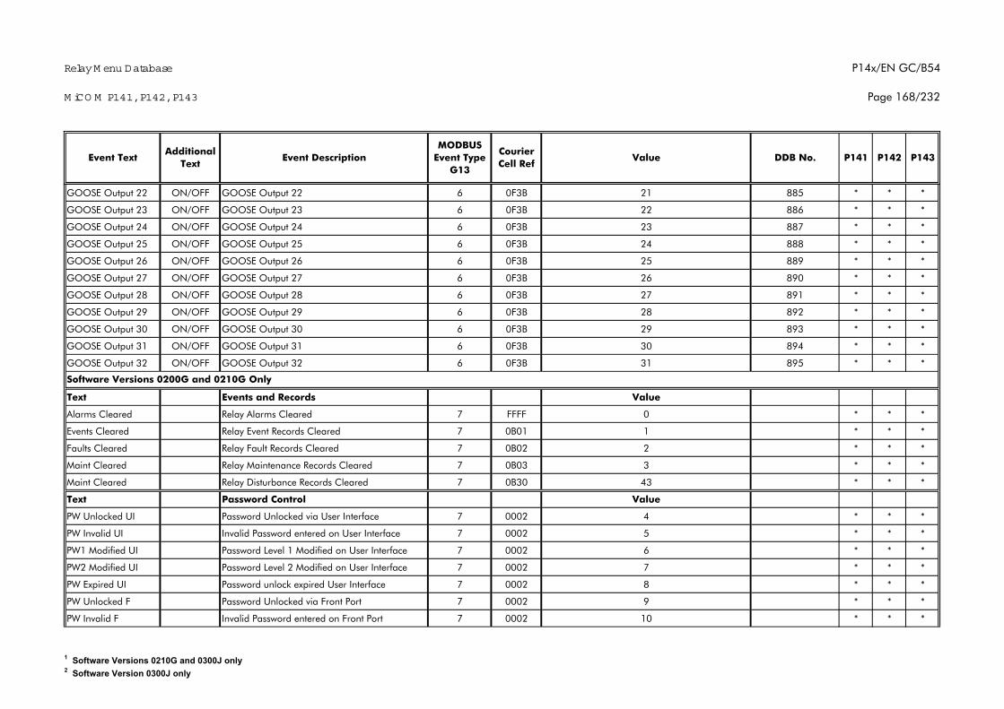
Relay M enu Database
M iCO M P141, P142, P143
P14x/EN GC/B54
Page 168/232
P142 P143Additional
TextEvent Text Event Description
MODBUS Event Type
G13
Courier Cell Ref
Value DDB No. P141
GOOSE Output 22 ON/OFF GOOSE Output 22 6 0F3B 21 885 * * *
GOOSE Output 23 ON/OFF GOOSE Output 23 6 0F3B 22 886 * * *
GOOSE Output 24 ON/OFF GOOSE Output 24 6 0F3B 23 887 * * *
GOOSE Output 25 ON/OFF GOOSE Output 25 6 0F3B 24 888 * * *
GOOSE Output 26 ON/OFF GOOSE Output 26 6 0F3B 25 889 * * *
GOOSE Output 27 ON/OFF GOOSE Output 27 6 0F3B 26 890 * * *
GOOSE Output 28 ON/OFF GOOSE Output 28 6 0F3B 27 891 * * *
GOOSE Output 29 ON/OFF GOOSE Output 29 6 0F3B 28 892 * * *
GOOSE Output 30 ON/OFF GOOSE Output 30 6 0F3B 29 893 * * *
GOOSE Output 31 ON/OFF GOOSE Output 31 6 0F3B 30 894 * * *
GOOSE Output 32 ON/OFF GOOSE Output 32 6 0F3B 31 895 * * *
Text Events and Records Value
Alarms Cleared Relay Alarms Cleared 7 FFFF 0 * * *
Events Cleared Relay Event Records Cleared 7 0B01 1 * * *
Faults Cleared Relay Fault Records Cleared 7 0B02 2 * * *
Maint Cleared Relay Maintenance Records Cleared 7 0B03 3 * * *
Maint Cleared Relay Disturbance Records Cleared 7 0B30 43 * * *
Text Password Control Value
PW Unlocked UI Password Unlocked via User Interface 7 0002 4 * * *
PW Invalid UI Invalid Password entered on User Interface 7 0002 5 * * *
PW1 Modified UI Password Level 1 Modified on User Interface 7 0002 6 * * *
PW2 Modified UI Password Level 2 Modified on User Interface 7 0002 7 * * *
PW Expired UI Password unlock expired User Interface 7 0002 8 * * *
PW Unlocked F Password Unlocked via Front Port 7 0002 9 * * *
PW Invalid F Invalid Password entered on Front Port 7 0002 10 * * *
Software Versions 0200G and 0210G Only
1 Software Versions 0210G and 0300J only2 Software Version 0300J only
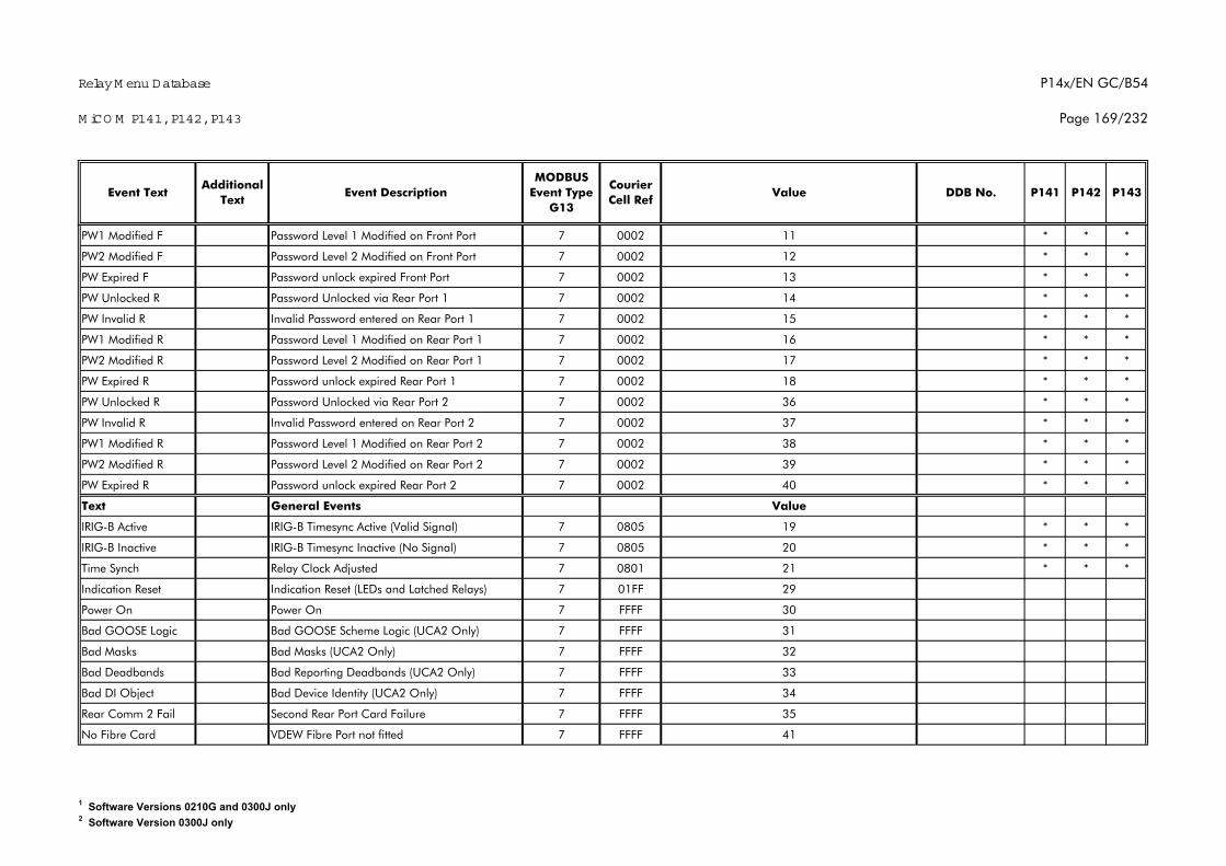
Relay M enu Database
M iCO M P141, P142, P143
P14x/EN GC/B54
Page 169/232
P142 P143Additional
TextEvent Text Event Description
MODBUS Event Type
G13
Courier Cell Ref
Value DDB No. P141
PW1 Modified F Password Level 1 Modified on Front Port 7 0002 11 * * *
PW2 Modified F Password Level 2 Modified on Front Port 7 0002 12 * * *
PW Expired F Password unlock expired Front Port 7 0002 13 * * *
PW Unlocked R Password Unlocked via Rear Port 1 7 0002 14 * * *
PW Invalid R Invalid Password entered on Rear Port 1 7 0002 15 * * *
PW1 Modified R Password Level 1 Modified on Rear Port 1 7 0002 16 * * *
PW2 Modified R Password Level 2 Modified on Rear Port 1 7 0002 17 * * *
PW Expired R Password unlock expired Rear Port 1 7 0002 18 * * *
PW Unlocked R Password Unlocked via Rear Port 2 7 0002 36 * * *
PW Invalid R Invalid Password entered on Rear Port 2 7 0002 37 * * *
PW1 Modified R Password Level 1 Modified on Rear Port 2 7 0002 38 * * *
PW2 Modified R Password Level 2 Modified on Rear Port 2 7 0002 39 * * *
PW Expired R Password unlock expired Rear Port 2 7 0002 40 * * *
Text General Events Value
IRIG-B Active IRIG-B Timesync Active (Valid Signal) 7 0805 19 * * *
IRIG-B Inactive IRIG-B Timesync Inactive (No Signal) 7 0805 20 * * *
Time Synch Relay Clock Adjusted 7 0801 21 * * *
Indication Reset Indication Reset (LEDs and Latched Relays) 7 01FF 29
Power On Power On 7 FFFF 30
Bad GOOSE Logic Bad GOOSE Scheme Logic (UCA2 Only) 7 FFFF 31
Bad Masks Bad Masks (UCA2 Only) 7 FFFF 32
Bad Deadbands Bad Reporting Deadbands (UCA2 Only) 7 FFFF 33
Bad DI Object Bad Device Identity (UCA2 Only) 7 FFFF 34
Rear Comm 2 Fail Second Rear Port Card Failure 7 FFFF 35
No Fibre Card VDEW Fibre Port not fitted 7 FFFF 41
1 Software Versions 0210G and 0300J only2 Software Version 0300J only
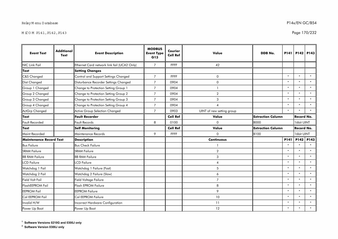
Relay M enu Database
M iCO M P141, P142, P143
P14x/EN GC/B54
Page 170/232
P142 P143Additional
TextEvent Text Event Description
MODBUS Event Type
G13
Courier Cell Ref
Value DDB No. P141
NIC Link Fail Ethernet Card network link fail (UCA2 Only) 7 FFFF 42
Text Setting Changes
C&S Changed Control and Support Settings Changed 7 FFFF 0 * * *
Dist Changed Disturbance Recorder Settings Changed 7 0904 0 * * *
Group 1 Changed Change to Protection Setting Group 1 7 0904 1 * * *
Group 2 Changed Change to Protection Setting Group 2 7 0904 2 * * *
Group 3 Changed Change to Protection Setting Group 3 7 0904 3 * * *
Group 4 Changed Change to Protection Setting Group 4 7 0904 4 * * *
ActGrp Changed Active Group Selection Changed 7 0903 UINT of new setting group * * *
Text Fault Recorder Cell Ref Value Extraction Column Record No.
Fault Recorded Fault Records 8 0100 0 B000 16bit UINT
Text Self Monitoring Cell Ref Value Extraction Column Record No.
Maint Recorded Maintenance Records 9 FFFF 0 B100 16bit UINT
Maintenance Record Text Description Continuous P141 P142 P143
Bus Failure Bus Check Failure 1 * * *
SRAM Failure SRAM Failure 2 * * *
BB RAM Failure BB RAM Failure 3 * * *
LCD Failure LCD Failure 4 * * *
Watchdog 1 Fail Watchdog 1 Failure (Fast) 5 * * *
Watchdog 2 Fail Watchdog 2 Failure (Slow) 6 * * *
Field Volt Fail Field Voltage Failure 7 * * *
FlashEEPROM Fail Flash EPROM Failure 8 * * *
EEPROM Fail EEPROM Failure 9 * * *
Cal EEPROM Fail Cal EEPROM Failure 10 * * *
Invalid H/W Incorrect Hardware Configuration 11 * * *
Power Up Boot Power Up Boot 12 * * *
1 Software Versions 0210G and 0300J only2 Software Version 0300J only
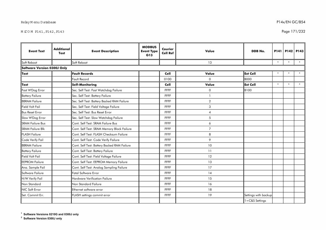
Relay M enu Database
M iCO M P141, P142, P143
P14x/EN GC/B54
Page 171/232
P142 P143Additional
TextEvent Text Event Description
MODBUS Event Type
G13
Courier Cell Ref
Value DDB No. P141
Soft Reboot Soft Reboot 13 * * *
Text Fault Records Cell Value Ext Cell * * *
Fault Record 0100 0 B000
Text Self-Monitoring Cell Value Ext Cell * * *
Fast W'Dog Error Sec. Self Test: Fast Watchdog Failure FFFF 0 B100
Battery Failure Sec. Self Test: Battery Failure FFFF 1
BBRAM Failure Sec. Self Test: Battery Backed RAM Failure FFFF 2
Field Volt Fail Sec. Self Test: Field Voltage Failure FFFF 3
Bus Reset Error Sec. Self Test: Bus Reset Error FFFF 4
Slow W'Dog Error Sec. Self Test: Slow Watchdog Failure FFFF 5
SRAM Failure Bus Cont. Self Test: SRAM Failure Bus FFFF 6
SRAM Failure Blk Cont. Self Test: SRAM Memory Block Failure FFFF 7
FLASH Failure Cont. Self Test: FLASH Checksum Failure FFFF 8
Code Verify Fail Cont. Self Test: Code Verify Failure FFFF 9
BBRAM Failure Cont. Self Test: Battery Backed RAM Failure FFFF 10
Battery Failure Cont. Self Test: Battery Failure FFFF 11
Field Volt Fail Cont. Self Test: Field Voltage Failure FFFF 12
EEPROM Failure Cont. Self Test: EEPROM Memory Failure FFFF 13
Ana. Sample Fail Cont. Self Test: Analog Sampling Failure FFFF 17
Software Failure Fatal Software Error FFFF 14
H/W Verify Fail Hardware Verification Failure FFFF 15
Non Standard Non Standard Failure FFFF 16
NIC Soft Error Ethernet software error FFFF 18
Set. Commit Err. FLASH settings commit error FFFF 19 Settings with backup
1=C&S Settings
Software Version 0300J Only
1 Software Versions 0210G and 0300J only2 Software Version 0300J only
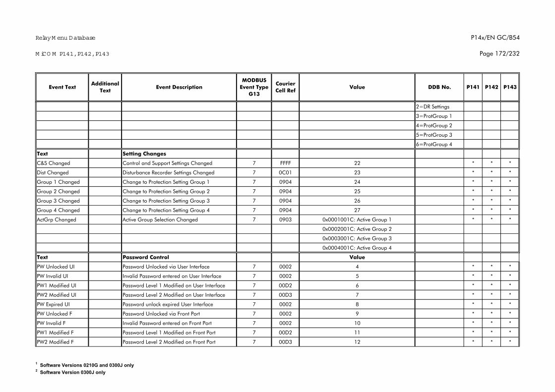
Relay M enu Database
M iCO M P141, P142, P143
P14x/EN GC/B54
Page 172/232
P142 P143Additional
TextEvent Text Event Description
MODBUS Event Type
G13
Courier Cell Ref
Value DDB No. P141
2=DR Settings
3=ProtGroup 1
4=ProtGroup 2
5=ProtGroup 3
6=ProtGroup 4
Text Setting Changes
C&S Changed Control and Support Settings Changed 7 FFFF 22 * * *
Dist Changed Disturbance Recorder Settings Changed 7 0C01 23 * * *
Group 1 Changed Change to Protection Setting Group 1 7 0904 24 * * *
Group 2 Changed Change to Protection Setting Group 2 7 0904 25 * * *
Group 3 Changed Change to Protection Setting Group 3 7 0904 26 * * *
Group 4 Changed Change to Protection Setting Group 4 7 0904 27 * * *
ActGrp Changed Active Group Selection Changed 7 0903 0x0001001C: Active Group 1 * * *
0x0002001C: Active Group 2
0x0003001C: Active Group 3
0x0004001C: Active Group 4
Text Password Control Value
PW Unlocked UI Password Unlocked via User Interface 7 0002 4 * * *
PW Invalid UI Invalid Password entered on User Interface 7 0002 5 * * *
PW1 Modified UI Password Level 1 Modified on User Interface 7 00D2 6 * * *
PW2 Modified UI Password Level 2 Modified on User Interface 7 00D3 7 * * *
PW Expired UI Password unlock expired User Interface 7 0002 8 * * *
PW Unlocked F Password Unlocked via Front Port 7 0002 9 * * *
PW Invalid F Invalid Password entered on Front Port 7 0002 10 * * *
PW1 Modified F Password Level 1 Modified on Front Port 7 00D2 11 * * *
PW2 Modified F Password Level 2 Modified on Front Port 7 00D3 12 * * *
1 Software Versions 0210G and 0300J only2 Software Version 0300J only
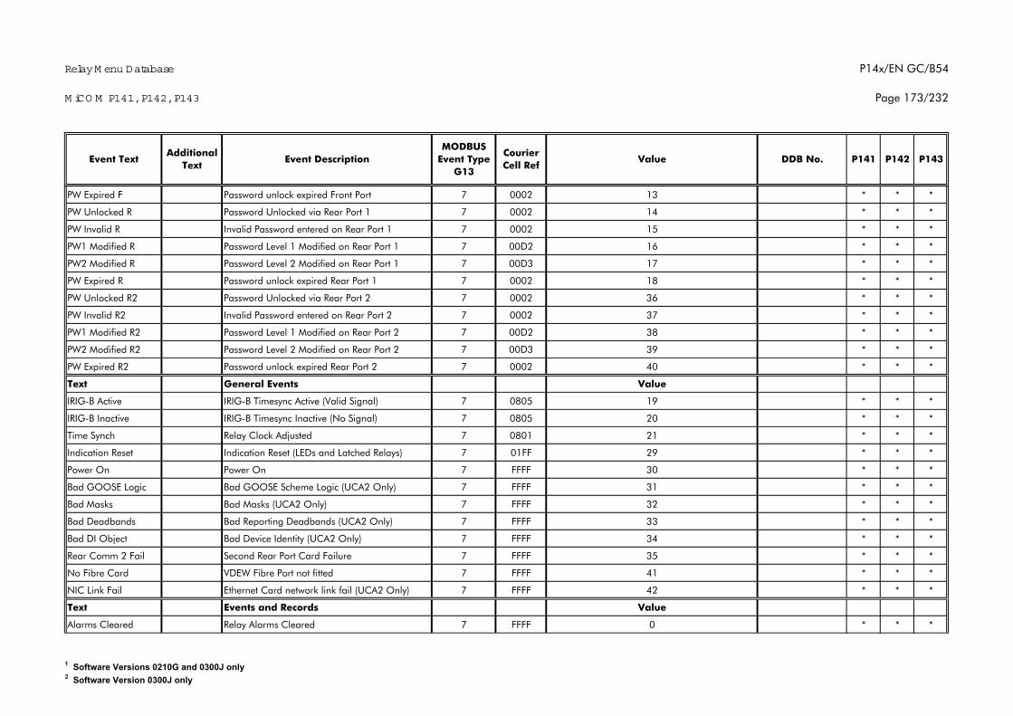
Relay M enu Database
M iCO M P141, P142, P143
P14x/EN GC/B54
Page 173/232
P142 P143Additional
TextEvent Text Event Description
MODBUS Event Type
G13
Courier Cell Ref
Value DDB No. P141
PW Expired F Password unlock expired Front Port 7 0002 13 * * *
PW Unlocked R Password Unlocked via Rear Port 1 7 0002 14 * * *
PW Invalid R Invalid Password entered on Rear Port 1 7 0002 15 * * *
PW1 Modified R Password Level 1 Modified on Rear Port 1 7 00D2 16 * * *
PW2 Modified R Password Level 2 Modified on Rear Port 1 7 00D3 17 * * *
PW Expired R Password unlock expired Rear Port 1 7 0002 18 * * *
PW Unlocked R2 Password Unlocked via Rear Port 2 7 0002 36 * * *
PW Invalid R2 Invalid Password entered on Rear Port 2 7 0002 37 * * *
PW1 Modified R2 Password Level 1 Modified on Rear Port 2 7 00D2 38 * * *
PW2 Modified R2 Password Level 2 Modified on Rear Port 2 7 00D3 39 * * *
PW Expired R2 Password unlock expired Rear Port 2 7 0002 40 * * *
Text General Events Value
IRIG-B Active IRIG-B Timesync Active (Valid Signal) 7 0805 19 * * *
IRIG-B Inactive IRIG-B Timesync Inactive (No Signal) 7 0805 20 * * *
Time Synch Relay Clock Adjusted 7 0801 21 * * *
Indication Reset Indication Reset (LEDs and Latched Relays) 7 01FF 29 * * *
Power On Power On 7 FFFF 30 * * *
Bad GOOSE Logic Bad GOOSE Scheme Logic (UCA2 Only) 7 FFFF 31 * * *
Bad Masks Bad Masks (UCA2 Only) 7 FFFF 32 * * *
Bad Deadbands Bad Reporting Deadbands (UCA2 Only) 7 FFFF 33 * * *
Bad DI Object Bad Device Identity (UCA2 Only) 7 FFFF 34 * * *
Rear Comm 2 Fail Second Rear Port Card Failure 7 FFFF 35 * * *
No Fibre Card VDEW Fibre Port not fitted 7 FFFF 41 * * *
NIC Link Fail Ethernet Card network link fail (UCA2 Only) 7 FFFF 42 * * *
Text Events and Records Value
Alarms Cleared Relay Alarms Cleared 7 FFFF 0 * * *
1 Software Versions 0210G and 0300J only2 Software Version 0300J only
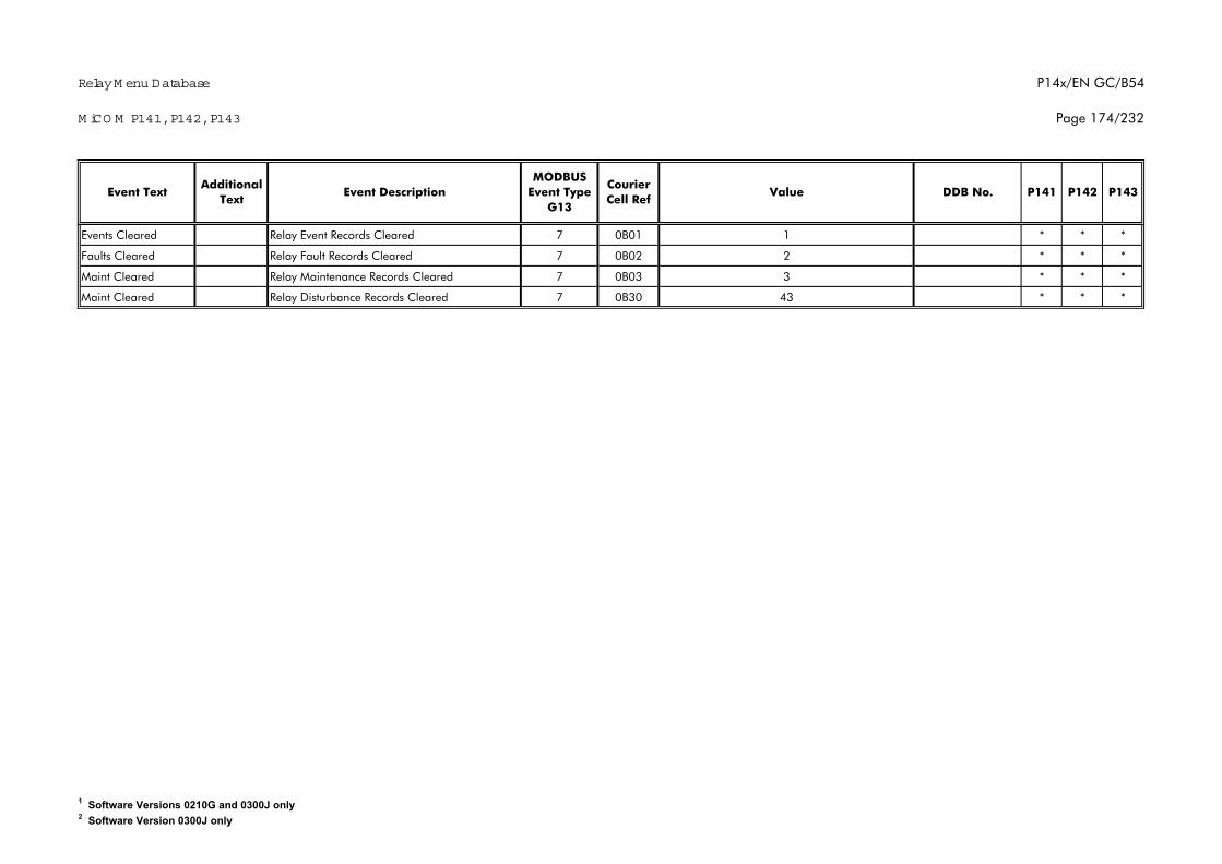
Relay M enu Database
M iCO M P141, P142, P143
P14x/EN GC/B54
Page 174/232
P142 P143Additional
TextEvent Text Event Description
MODBUS Event Type
G13
Courier Cell Ref
Value DDB No. P141
Events Cleared Relay Event Records Cleared 7 0B01 1 * * *
Faults Cleared Relay Fault Records Cleared 7 0B02 2 * * *
Maint Cleared Relay Maintenance Records Cleared 7 0B03 3 * * *
Maint Cleared Relay Disturbance Records Cleared 7 0B30 43 * * *
1 Software Versions 0210G and 0300J only2 Software Version 0300J only
Relay Menu Database P14x/EN GC/B54
MiCOM P141, P142, P143 Page 175/232
1. INTRODUCTION
The purpose of this document is to describe the specific implementation of theDistributed Network Protocol (DNP) version 3.0 within MiCOM 140 relays.
The MiCOM P140 uses the Triangle MicroWorks, Inc. DNP 3.0 Slave Source CodeLibrary version 2.32.
This document, in conjunction with the DNP 3.0 Basic 4 Document Set, and the DNPSubset Definitions Document, provides complete information on how to communicatewith P140 relays using the DNP 3.0 protocol.
This implementation of DNP 3.0 is fully compliant with DNP 3.0 Subset DefinitionLevel 2. It also contains many Subset Level 3 and above features.
2. DNP V3.0 DEVICE PROFILE
The following table provides a “Device Profile Document” in the standard formatdefined in the DNP 3.0 Subset Definitions Document. While it is referred to in theDNP 3.0 Subset Definitions as a “Document”, it is only a component of a totalinteroperability guide. This table, in combination with the following should provide acomplete interoperability/configuration guide for the P140 range of MiCOM relays:
• The Implementation Table provided in section §3
• The Point List Tables provided in section §6
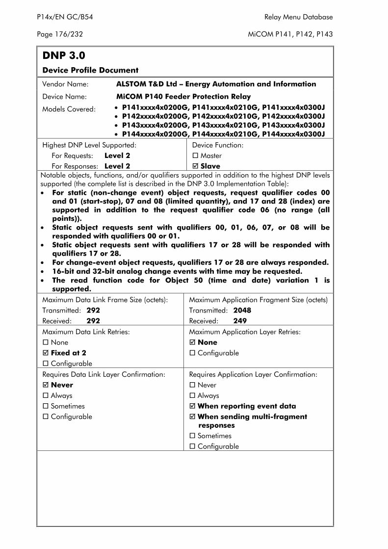
P14x/EN GC/B54 Relay Menu Database
Page 176/232 MiCOM P141, P142, P143
DNP 3.0Device Profile Document
Vendor Name: ALSTOM T&D Ltd – Energy Automation and Information
Device Name: MiCOM P140 Feeder Protection Relay
Models Covered: • P141xxxx4x0200G, P141xxxx4x0210G, P141xxxx4x0300J• P142xxxx4x0200G, P142xxxx4x0210G, P142xxxx4x0300J• P143xxxx4x0200G, P143xxxx4x0210G, P143xxxx4x0300J• P144xxxx4x0200G, P144xxxx4x0210G, P144xxxx4x0300J
Highest DNP Level Supported:For Requests: Level 2For Responses: Level 2
Device Function:� Master� Slave
Notable objects, functions, and/or qualifiers supported in addition to the highest DNP levelssupported (the complete list is described in the DNP 3.0 Implementation Table):• For static (non-change event) object requests, request qualifier codes 00
and 01 (start-stop), 07 and 08 (limited quantity), and 17 and 28 (index) aresupported in addition to the request qualifier code 06 (no range (allpoints)).
• Static object requests sent with qualifiers 00, 01, 06, 07, or 08 will beresponded with qualifiers 00 or 01.
• Static object requests sent with qualifiers 17 or 28 will be responded withqualifiers 17 or 28.
• For change-event object requests, qualifiers 17 or 28 are always responded.• 16-bit and 32-bit analog change events with time may be requested.• The read function code for Object 50 (time and date) variation 1 is
supported.
Maximum Data Link Frame Size (octets):Transmitted: 292Received: 292
Maximum Application Fragment Size (octets)Transmitted: 2048Received: 249
Maximum Data Link Retries:� None� Fixed at 2� Configurable
Maximum Application Layer Retries:� None� Configurable
Requires Data Link Layer Confirmation:� Never� Always� Sometimes� Configurable
Requires Application Layer Confirmation:� Never� Always� When reporting event data� When sending multi-fragment
responses� Sometimes� Configurable
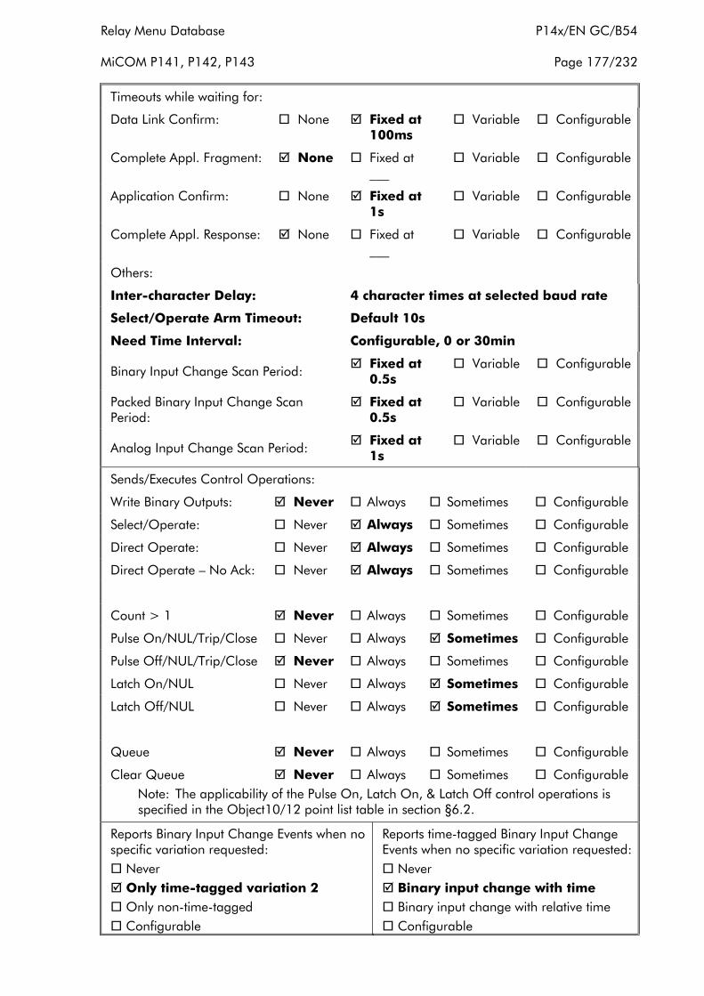
Relay Menu Database P14x/EN GC/B54
MiCOM P141, P142, P143 Page 177/232
Timeouts while waiting for:
Data Link Confirm: � None � Fixed at 100ms
� Variable � Configurable
Complete Appl. Fragment: � None � Fixed at ___
� Variable � Configurable
Application Confirm: � None � Fixed at 1s
� Variable � Configurable
Complete Appl. Response: � None � Fixed at ___
� Variable � Configurable
Others:
Inter-character Delay: 4 character times at selected baud rate
Select/Operate Arm Timeout: Default 10s
Need Time Interval: Configurable, 0 or 30min
Binary Input Change Scan Period: � Fixed at 0.5s
� Variable � Configurable
Packed Binary Input Change ScanPeriod:
� Fixed at 0.5s
� Variable � Configurable
Analog Input Change Scan Period: � Fixed at 1s
� Variable � Configurable
Sends/Executes Control Operations:
Write Binary Outputs: � Never � Always � Sometimes � Configurable
Select/Operate: � Never � Always � Sometimes � Configurable
Direct Operate: � Never � Always � Sometimes � Configurable
Direct Operate – No Ack: � Never � Always � Sometimes � Configurable
Count > 1 � Never � Always � Sometimes � Configurable
Pulse On/NUL/Trip/Close � Never � Always � Sometimes � Configurable
Pulse Off/NUL/Trip/Close � Never � Always � Sometimes � Configurable
Latch On/NUL � Never � Always � Sometimes � Configurable
Latch Off/NUL � Never � Always � Sometimes � Configurable
Queue � Never � Always � Sometimes � Configurable
Clear Queue � Never � Always � Sometimes � ConfigurableNote: The applicability of the Pulse On, Latch On, & Latch Off control operations is specified in the Object10/12 point list table in section §6.2.
Reports Binary Input Change Events when nospecific variation requested:� Never� Only time-tagged variation 2� Only non-time-tagged� Configurable
Reports time-tagged Binary Input ChangeEvents when no specific variation requested:� Never� Binary input change with time� Binary input change with relative time� Configurable
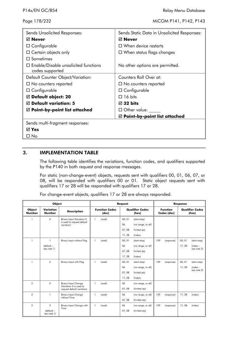
P14x/EN GC/B54 Relay Menu Database
Page 178/232 MiCOM P141, P142, P143
Sends Unsolicited Responses:� Never� Configurable� Certain objects only� Sometimes� Enable/Disable unsolicited functions
codes supported
Sends Static Data in Unsolicited Responses:� Never� When device restarts� When status flags changes
No other options are permitted.
Default Counter Object/Variation:� No counters reported� Configurable� Default object: 20� Default variation: 5� Point-by-point list attached
Counters Roll Over at:� No counters reported� Configurable� 16 bits� 32 bits� Other value: _____� Point-by-point list attached
Sends multi-fragment responses:� Yes� No
3. IMPLEMENTATION TABLE
The following table identifies the variations, function codes, and qualifiers supportedby the P140 in both request and response messages.
For static (non-change-event) objects, requests sent with qualifiers 00, 01, 06, 07, or08, will be responded with qualifiers 00 or 01. Static object requests sent withqualifiers 17 or 28 will be responded with qualifiers 17 or 28.
For change-event objects, qualifiers 17 or 28 are always responded.
Object Request Response
ObjectNumber
VariationNumber
DescriptionFunction Codes
(dec)Qualifier Codes
(hex)Function
Codes (dec)Qualifier Codes
(hex)
1 0 Binary Input (Variation 0is used to request defaultvariation)
1 (read) 00, 01
06
07, 08
17, 28
(start-stop)
(no range, or all)
limited qty)
(index)
1 1
(default –see note 1)
Binary Input without Flag 1 (read) 00, 01
06
07, 08
17, 28
(start-stop)
(no range, or all)
limited qty)
(index)
129 (response) 00, 01
17, 28
(start-stop)
(index –see note 2)
1 2 Binary Input with Flag 1 (read) 00, 01
06
07, 08
17, 28
(start-stop)
(no range, or all)
limited qty)
(index)
129 (response) 00, 01
17, 28
(start-stop)
(index –see note 2)
2 0 Binary Input Change(Variation 0 is used torequest default variation)
1 (read) 06
07, 08
(no range, or all)
(limited qty)
2 1 Binary Input Changewithout Time
1 (read) 06
07, 08
(no range, or all)
(limited qty)
129 (response) 17, 28 (index)
2 2
(default –see note 1)
Binary Input Change withTime
1 (read) 06
07, 08
(no range, or all)
(limited qty)
129 (response) 17, 28 (index)
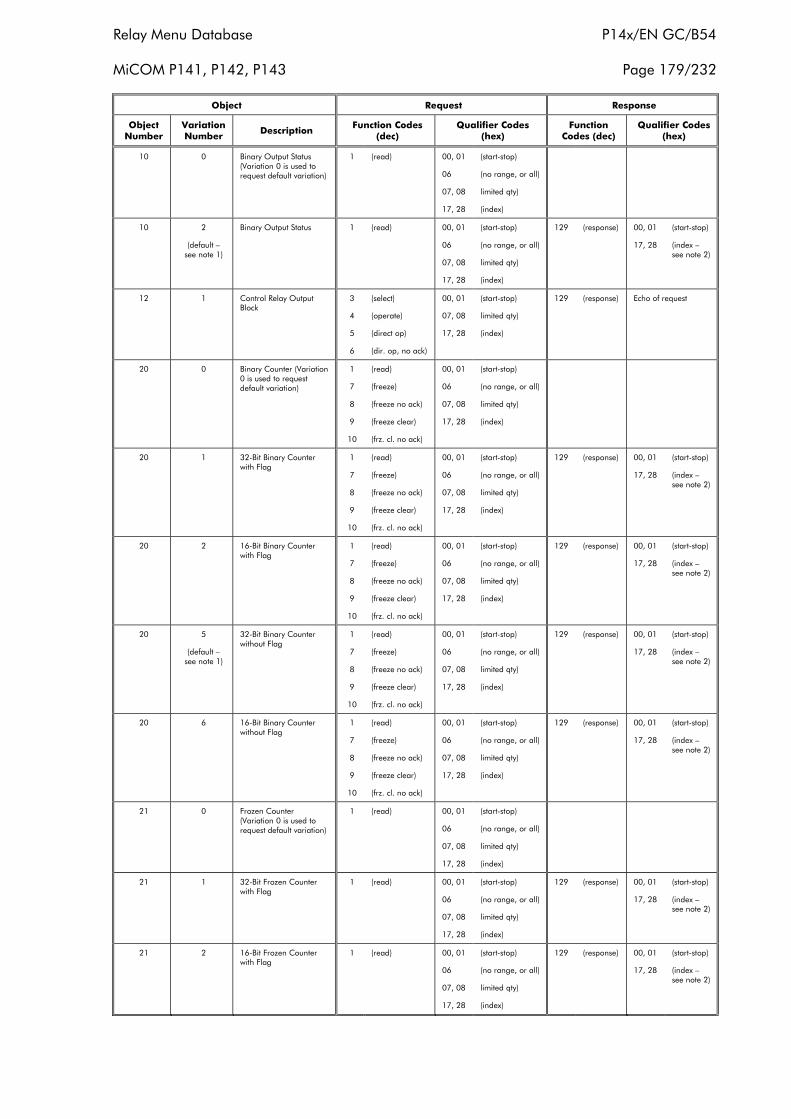
Relay Menu Database P14x/EN GC/B54
MiCOM P141, P142, P143 Page 179/232
Object Request Response
ObjectNumber
VariationNumber
DescriptionFunction Codes
(dec)Qualifier Codes
(hex)Function
Codes (dec)Qualifier Codes
(hex)
10 0 Binary Output Status(Variation 0 is used torequest default variation)
1 (read) 00, 01
06
07, 08
17, 28
(start-stop)
(no range, or all)
limited qty)
(index)
10 2
(default –see note 1)
Binary Output Status 1 (read) 00, 01
06
07, 08
17, 28
(start-stop)
(no range, or all)
limited qty)
(index)
129 (response) 00, 01
17, 28
(start-stop)
(index –see note 2)
12 1 Control Relay OutputBlock
3
4
5
6
(select)
(operate)
(direct op)
(dir. op, no ack)
00, 01
07, 08
17, 28
(start-stop)
limited qty)
(index)
129 (response) Echo of request
20 0 Binary Counter (Variation0 is used to requestdefault variation)
1
7
8
9
10
(read)
(freeze)
(freeze no ack)
(freeze clear)
(frz. cl. no ack)
00, 01
06
07, 08
17, 28
(start-stop)
(no range, or all)
limited qty)
(index)
20 1 32-Bit Binary Counterwith Flag
1
7
8
9
10
(read)
(freeze)
(freeze no ack)
(freeze clear)
(frz. cl. no ack)
00, 01
06
07, 08
17, 28
(start-stop)
(no range, or all)
limited qty)
(index)
129 (response) 00, 01
17, 28
(start-stop)
(index –see note 2)
20 2 16-Bit Binary Counterwith Flag
1
7
8
9
10
(read)
(freeze)
(freeze no ack)
(freeze clear)
(frz. cl. no ack)
00, 01
06
07, 08
17, 28
(start-stop)
(no range, or all)
limited qty)
(index)
129 (response) 00, 01
17, 28
(start-stop)
(index –see note 2)
20 5
(default –see note 1)
32-Bit Binary Counterwithout Flag
1
7
8
9
10
(read)
(freeze)
(freeze no ack)
(freeze clear)
(frz. cl. no ack)
00, 01
06
07, 08
17, 28
(start-stop)
(no range, or all)
limited qty)
(index)
129 (response) 00, 01
17, 28
(start-stop)
(index –see note 2)
20 6 16-Bit Binary Counterwithout Flag
1
7
8
9
10
(read)
(freeze)
(freeze no ack)
(freeze clear)
(frz. cl. no ack)
00, 01
06
07, 08
17, 28
(start-stop)
(no range, or all)
limited qty)
(index)
129 (response) 00, 01
17, 28
(start-stop)
(index –see note 2)
21 0 Frozen Counter(Variation 0 is used torequest default variation)
1 (read) 00, 01
06
07, 08
17, 28
(start-stop)
(no range, or all)
limited qty)
(index)
21 1 32-Bit Frozen Counterwith Flag
1 (read) 00, 01
06
07, 08
17, 28
(start-stop)
(no range, or all)
limited qty)
(index)
129 (response) 00, 01
17, 28
(start-stop)
(index –see note 2)
21 2 16-Bit Frozen Counterwith Flag
1 (read) 00, 01
06
07, 08
17, 28
(start-stop)
(no range, or all)
limited qty)
(index)
129 (response) 00, 01
17, 28
(start-stop)
(index –see note 2)
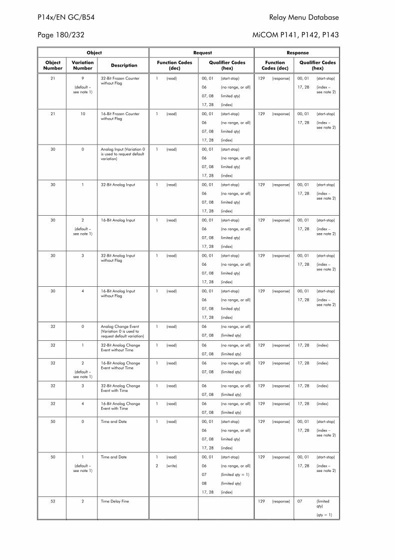
P14x/EN GC/B54 Relay Menu Database
Page 180/232 MiCOM P141, P142, P143
Object Request Response
ObjectNumber
VariationNumber
DescriptionFunction Codes
(dec)Qualifier Codes
(hex)Function
Codes (dec)Qualifier Codes
(hex)
21 9
(default –see note 1)
32-Bit Frozen Counterwithout Flag
1 (read) 00, 01
06
07, 08
17, 28
(start-stop)
(no range, or all)
limited qty)
(index)
129 (response) 00, 01
17, 28
(start-stop)
(index –see note 2)
21 10 16-Bit Frozen Counterwithout Flag
1 (read) 00, 01
06
07, 08
17, 28
(start-stop)
(no range, or all)
limited qty)
(index)
129 (response) 00, 01
17, 28
(start-stop)
(index –see note 2)
30 0 Analog Input (Variation 0is used to request defaultvariation)
1 (read) 00, 01
06
07, 08
17, 28
(start-stop)
(no range, or all)
limited qty)
(index)
30 1 32-Bit Analog Input 1 (read) 00, 01
06
07, 08
17, 28
(start-stop)
(no range, or all)
limited qty)
(index)
129 (response) 00, 01
17, 28
(start-stop)
(index –see note 2)
30 2
(default –see note 1)
16-Bit Analog Input 1 (read) 00, 01
06
07, 08
17, 28
(start-stop)
(no range, or all)
limited qty)
(index)
129 (response) 00, 01
17, 28
(start-stop)
(index –see note 2)
30 3 32-Bit Analog Inputwithout Flag
1 (read) 00, 01
06
07, 08
17, 28
(start-stop)
(no range, or all)
limited qty)
(index)
129 (response) 00, 01
17, 28
(start-stop)
(index –see note 2)
30 4 16-Bit Analog Inputwithout Flag
1 (read) 00, 01
06
07, 08
17, 28
(start-stop)
(no range, or all)
limited qty)
(index)
129 (response) 00, 01
17, 28
(start-stop)
(index –see note 2)
32 0 Analog Change Event(Variation 0 is used torequest default variation)
1 (read) 06
07, 08
(no range, or all)
(limited qty)
32 1 32-Bit Analog ChangeEvent without Time
1 (read) 06
07, 08
(no range, or all)
(limited qty)
129 (response) 17, 28 (index)
32 2
(default –see note 1)
16-Bit Analog ChangeEvent without Time
1 (read) 06
07, 08
(no range, or all)
(limited qty)
129 (response) 17, 28 (index)
32 3 32-Bit Analog ChangeEvent with Time
1 (read) 06
07, 08
(no range, or all)
(limited qty)
129 (response) 17, 28 (index)
32 4 16-Bit Analog ChangeEvent with Time
1 (read) 06
07, 08
(no range, or all)
(limited qty)
129 (response) 17, 28 (index)
50 0 Time and Date 1 (read) 00, 01
06
07, 08
17, 28
(start-stop)
(no range, or all)
limited qty)
(index)
129 (response) 00, 01
17, 28
(start-stop)
(index –see note 2)
50 1
(default –see note 1)
Time and Date 1
2
(read)
(write)
00, 01
06
07
08
17, 28
(start-stop)
(no range, or all)
(limited qty = 1)
(limited qty)
(index)
129 (response) 00, 01
17, 28
(start-stop)
(index –see note 2)
52 2 Time Delay Fine 129 (response) 07 (limitedqty)
(qty = 1)
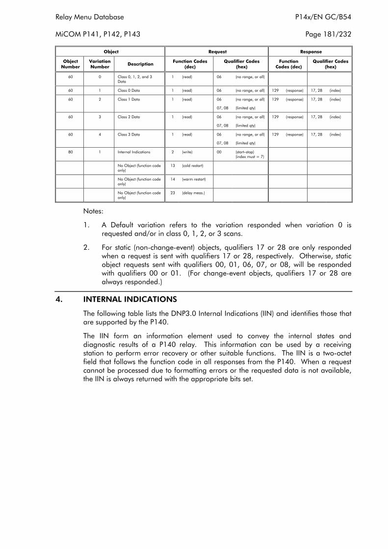
Relay Menu Database P14x/EN GC/B54
MiCOM P141, P142, P143 Page 181/232
Object Request Response
ObjectNumber
VariationNumber
DescriptionFunction Codes
(dec)Qualifier Codes
(hex)Function
Codes (dec)Qualifier Codes
(hex)
60 0 Class 0, 1, 2, and 3Data
1 (read) 06 (no range, or all)
60 1 Class 0 Data 1 (read) 06 (no range, or all) 129 (response) 17, 28 (index)
60 2 Class 1 Data 1 (read) 06
07, 08
(no range, or all)
(limited qty)
129 (response) 17, 28 (index)
60 3 Class 2 Data 1 (read) 06
07, 08
(no range, or all)
(limited qty)
129 (response) 17, 28 (index)
60 4 Class 3 Data 1 (read) 06
07, 08
(no range, or all)
(limited qty)
129 (response) 17, 28 (index)
80 1 Internal Indications 2 (write) 00 (start–stop)(index must = 7)
No Object (function codeonly)
13 (cold restart)
No Object (function codeonly)
14 (warm restart)
No Object (function codeonly)
23 (delay meas.)
Notes:
1. A Default variation refers to the variation responded when variation 0 isrequested and/or in class 0, 1, 2, or 3 scans.
2. For static (non-change-event) objects, qualifiers 17 or 28 are only respondedwhen a request is sent with qualifiers 17 or 28, respectively. Otherwise, staticobject requests sent with qualifiers 00, 01, 06, 07, or 08, will be respondedwith qualifiers 00 or 01. (For change-event objects, qualifiers 17 or 28 arealways responded.)
4. INTERNAL INDICATIONS
The following table lists the DNP3.0 Internal Indications (IIN) and identifies those thatare supported by the P140.
The IIN form an information element used to convey the internal states anddiagnostic results of a P140 relay. This information can be used by a receivingstation to perform error recovery or other suitable functions. The IIN is a two-octetfield that follows the function code in all responses from the P140. When a requestcannot be processed due to formatting errors or the requested data is not available,the IIN is always returned with the appropriate bits set.
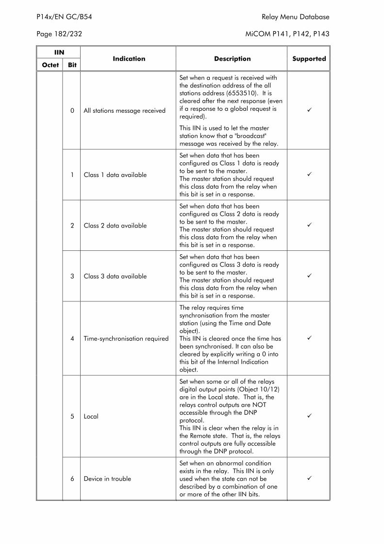
P14x/EN GC/B54 Relay Menu Database
Page 182/232 MiCOM P141, P142, P143
IIN
Octet BitIndication Description Supported
0 All stations message received
Set when a request is received withthe destination address of the allstations address (6553510). It iscleared after the next response (evenif a response to a global request isrequired).
This IIN is used to let the masterstation know that a "broadcast"message was received by the relay.
�
1 Class 1 data available
Set when data that has beenconfigured as Class 1 data is readyto be sent to the master.The master station should requestthis class data from the relay whenthis bit is set in a response.
�
2 Class 2 data available
Set when data that has beenconfigured as Class 2 data is readyto be sent to the master.The master station should requestthis class data from the relay whenthis bit is set in a response.
�
3 Class 3 data available
Set when data that has beenconfigured as Class 3 data is readyto be sent to the master.The master station should requestthis class data from the relay whenthis bit is set in a response.
�
4 Time-synchronisation required
The relay requires timesynchronisation from the masterstation (using the Time and Dateobject).This IIN is cleared once the time hasbeen synchronised. It can also becleared by explicitly writing a 0 intothis bit of the Internal Indicationobject.
�
5 Local
Set when some or all of the relaysdigital output points (Object 10/12)are in the Local state. That is, therelays control outputs are NOTaccessible through the DNPprotocol.This IIN is clear when the relay is inthe Remote state. That is, the relayscontrol outputs are fully accessiblethrough the DNP protocol.
�
6 Device in trouble
Set when an abnormal conditionexists in the relay. This IIN is onlyused when the state can not bedescribed by a combination of oneor more of the other IIN bits.
�
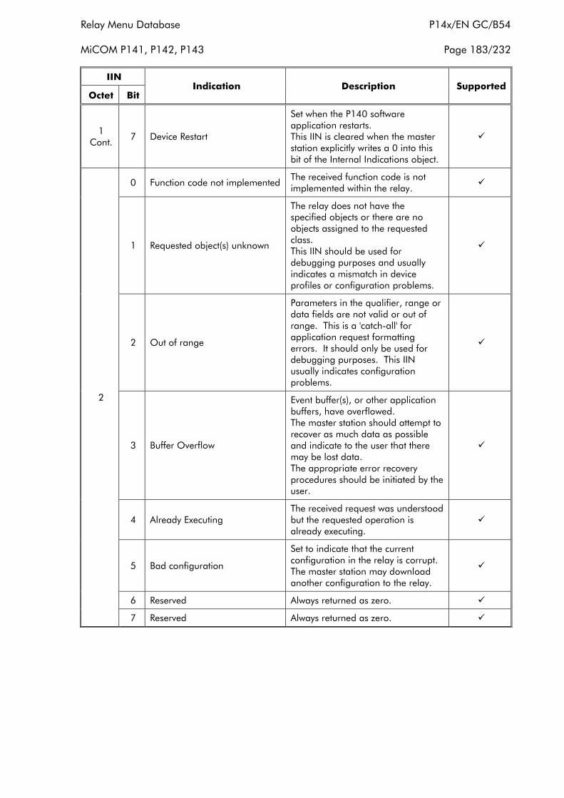
Relay Menu Database P14x/EN GC/B54
MiCOM P141, P142, P143 Page 183/232
IIN
Octet BitIndication Description Supported
1Cont.
7 Device Restart
Set when the P140 softwareapplication restarts.This IIN is cleared when the masterstation explicitly writes a 0 into thisbit of the Internal Indications object.
�
0 Function code not implementedThe received function code is notimplemented within the relay.
�
1 Requested object(s) unknown
The relay does not have thespecified objects or there are noobjects assigned to the requestedclass.This IIN should be used fordebugging purposes and usuallyindicates a mismatch in deviceprofiles or configuration problems.
�
2 Out of range
Parameters in the qualifier, range ordata fields are not valid or out ofrange. This is a 'catch-all' forapplication request formattingerrors. It should only be used fordebugging purposes. This IINusually indicates configurationproblems.
�
3 Buffer Overflow
Event buffer(s), or other applicationbuffers, have overflowed.The master station should attempt torecover as much data as possibleand indicate to the user that theremay be lost data.The appropriate error recoveryprocedures should be initiated by theuser.
�
4 Already ExecutingThe received request was understoodbut the requested operation isalready executing.
�
5 Bad configuration
Set to indicate that the currentconfiguration in the relay is corrupt.The master station may downloadanother configuration to the relay.
�
6 Reserved Always returned as zero. �
2
7 Reserved Always returned as zero. �
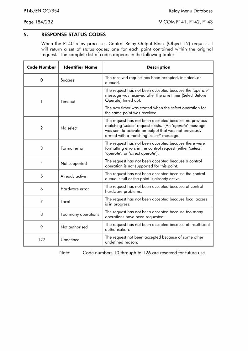
P14x/EN GC/B54 Relay Menu Database
Page 184/232 MiCOM P141, P142, P143
5. RESPONSE STATUS CODES
When the P140 relay processes Control Relay Output Block (Object 12) requests itwill return a set of status codes; one for each point contained within the originalrequest. The complete list of codes appears in the following table:
Code Number Identifier Name Description
0 Success The received request has been accepted, initiated, orqueued.
1 Timeout
The request has not been accepted because the ‘operate’message was received after the arm timer (Select BeforeOperate) timed out.
The arm timer was started when the select operation forthe same point was received.
2 No select
The request has not been accepted because no previousmatching ‘select’ request exists. (An ‘operate’ messagewas sent to activate an output that was not previouslyarmed with a matching ‘select’ message.)
3 Format errorThe request has not been accepted because there wereformatting errors in the control request (either ‘select’,‘operate’, or ‘direct operate’).
4 Not supportedThe request has not been accepted because a controloperation is not supported for this point.
5 Already activeThe request has not been accepted because the controlqueue is full or the point is already active.
6 Hardware errorThe request has not been accepted because of controlhardware problems.
7 LocalThe request has not been accepted because local accessis in progress.
8 Too many operationsThe request has not been accepted because too manyoperations have been requested.
9 Not authorisedThe request has not been accepted because of insufficientauthorisation.
127 UndefinedThe request not been accepted because of some otherundefined reason.
Note: Code numbers 10 through to 126 are reserved for future use.
Relay Menu Database P14x/EN GC/B54
MiCOM P141, P142, P143 Page 185/232
6. POINT LIST
The tables in the following sections identify all the individual data points provided bythis implementation of DNP 3.0.
6.1 Binary input points
The Binary Input objects (1 & 2) provide read-only access to a sub-set of the P140’sDigital Data Bus (DDB).
By default, all the static object (object 1) points belong to the Class 0 data set. Thedefault allocation of the points in the change-event object (object 2) to a change-event class (1, 2, 3) is indicated in the point-list table below. The MiCOM S1 settingsupport software may be used to alter both of these assignments. However,deselecting a point from class 0 also has the effect of removing the point from thepoint-list of objects 1 & 2 and renumbering the remaining points to ensure the pointindices are contiguous.
The validity of each point is reported through the “online” bit in the “flag”, which issupplied for each point with the “with flag” object variations. Points reported asbeing offline, will typically be points that are invalid for the relay’s currentconfiguration, which is a product of its model number and current settings.

P14x/EN GC/B54 Relay Menu Database
Page 186/232 MiCOM P141, P142, P143
Binary Input Points (Software Versions 0200G and 0210G only)Static (Steady-State) Object Number: 1Change Event Object Number: 2Request Function Codes supported: 1 (read)Static Variation reported when variation 0 requested: 1 (Binary Input without status)Change Event Variation reported when variation 0 requested: 2 (Binary Input Change with time)
P141PointIndex
P142PointIndex
P143PointIndex
Name/Description
DD
B N
O
DefaultChange
Event Class(1, 2, 3, or
none)
Pa
cked
Po
int
Un
pa
cked
Po
int
Output Relay Status
0 0 0 Output Relay 1 0 2 *
1 1 1 Output Relay 2 1 2 *
2 2 2 Output Relay 3 2 2 *
3 3 3 Output Relay 4 3 2 *
4 4 4 Output Relay 5 4 2 *
5 5 5 Output Relay 6 5 2 *
6 6 6 Output Relay 7 6 2 *
7 7 Output Relay 8 7 2 *
8 8 Output Relay 9 8 2 *
9 9 Output Relay 10 9 2 *
10 10 Output Relay 11 10 2 *
11 11 Output Relay 12 11 2 *
12 12 Output Relay 13 12 2 *
13 13 Output Relay 14 13 2 *
14 14 Output Relay 15 14 2 *
15 Output Relay 16 15 2 *
16 Output Relay 17 16 2 *
17 Output Relay 18 17 2 *
18 Output Relay 19 18 2 *
19 Output Relay 20 19 2 *
20 Output Relay 21 20 2 *
21 Output Relay 22 21 2 *
22 Output Relay 23 22 2 *
23 Output Relay 24 23 2 *
24 Output Relay 25 24 2 *
25 Output Relay 26 25 2 *
26 Output Relay 27 26 2 *
27 Output Relay 28 27 2 *
28 Output Relay 29 28 2 *
29 Output Relay 30 29 2 *
Opto Isolator Status
7 15 30 Opto Isolator 1 32 2 *
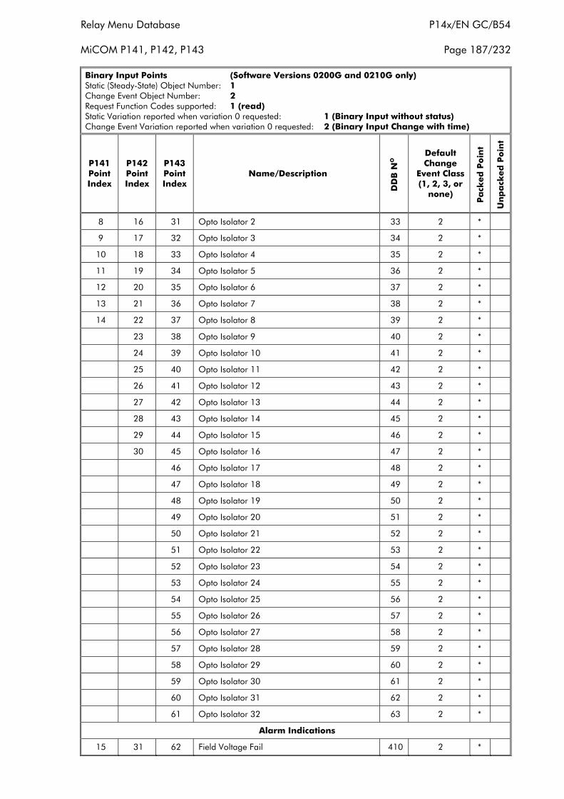
Relay Menu Database P14x/EN GC/B54
MiCOM P141, P142, P143 Page 187/232
Binary Input Points (Software Versions 0200G and 0210G only)Static (Steady-State) Object Number: 1Change Event Object Number: 2Request Function Codes supported: 1 (read)Static Variation reported when variation 0 requested: 1 (Binary Input without status)Change Event Variation reported when variation 0 requested: 2 (Binary Input Change with time)
P141PointIndex
P142PointIndex
P143PointIndex
Name/Description
DD
B N
O
DefaultChange
Event Class(1, 2, 3, or
none)
Pa
cked
Po
int
Un
pa
cked
Po
int
8 16 31 Opto Isolator 2 33 2 *
9 17 32 Opto Isolator 3 34 2 *
10 18 33 Opto Isolator 4 35 2 *
11 19 34 Opto Isolator 5 36 2 *
12 20 35 Opto Isolator 6 37 2 *
13 21 36 Opto Isolator 7 38 2 *
14 22 37 Opto Isolator 8 39 2 *
23 38 Opto Isolator 9 40 2 *
24 39 Opto Isolator 10 41 2 *
25 40 Opto Isolator 11 42 2 *
26 41 Opto Isolator 12 43 2 *
27 42 Opto Isolator 13 44 2 *
28 43 Opto Isolator 14 45 2 *
29 44 Opto Isolator 15 46 2 *
30 45 Opto Isolator 16 47 2 *
46 Opto Isolator 17 48 2 *
47 Opto Isolator 18 49 2 *
48 Opto Isolator 19 50 2 *
49 Opto Isolator 20 51 2 *
50 Opto Isolator 21 52 2 *
51 Opto Isolator 22 53 2 *
52 Opto Isolator 23 54 2 *
53 Opto Isolator 24 55 2 *
54 Opto Isolator 25 56 2 *
55 Opto Isolator 26 57 2 *
56 Opto Isolator 27 58 2 *
57 Opto Isolator 28 59 2 *
58 Opto Isolator 29 60 2 *
59 Opto Isolator 30 61 2 *
60 Opto Isolator 31 62 2 *
61 Opto Isolator 32 63 2 *
Alarm Indications
15 31 62 Field Voltage Fail 410 2 *
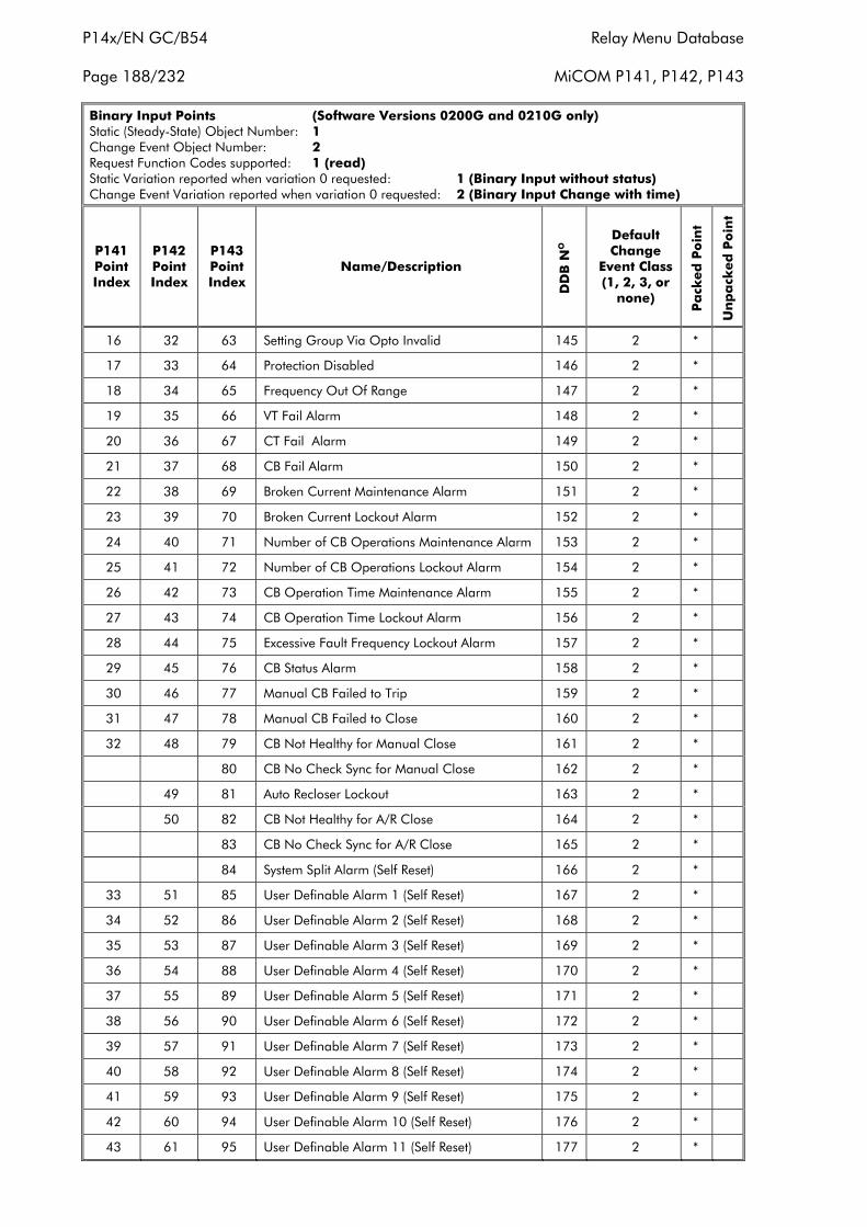
P14x/EN GC/B54 Relay Menu Database
Page 188/232 MiCOM P141, P142, P143
Binary Input Points (Software Versions 0200G and 0210G only)Static (Steady-State) Object Number: 1Change Event Object Number: 2Request Function Codes supported: 1 (read)Static Variation reported when variation 0 requested: 1 (Binary Input without status)Change Event Variation reported when variation 0 requested: 2 (Binary Input Change with time)
P141PointIndex
P142PointIndex
P143PointIndex
Name/Description
DD
B N
O
DefaultChange
Event Class(1, 2, 3, or
none)
Pa
cked
Po
int
Un
pa
cked
Po
int
16 32 63 Setting Group Via Opto Invalid 145 2 *
17 33 64 Protection Disabled 146 2 *
18 34 65 Frequency Out Of Range 147 2 *
19 35 66 VT Fail Alarm 148 2 *
20 36 67 CT Fail Alarm 149 2 *
21 37 68 CB Fail Alarm 150 2 *
22 38 69 Broken Current Maintenance Alarm 151 2 *
23 39 70 Broken Current Lockout Alarm 152 2 *
24 40 71 Number of CB Operations Maintenance Alarm 153 2 *
25 41 72 Number of CB Operations Lockout Alarm 154 2 *
26 42 73 CB Operation Time Maintenance Alarm 155 2 *
27 43 74 CB Operation Time Lockout Alarm 156 2 *
28 44 75 Excessive Fault Frequency Lockout Alarm 157 2 *
29 45 76 CB Status Alarm 158 2 *
30 46 77 Manual CB Failed to Trip 159 2 *
31 47 78 Manual CB Failed to Close 160 2 *
32 48 79 CB Not Healthy for Manual Close 161 2 *
80 CB No Check Sync for Manual Close 162 2 *
49 81 Auto Recloser Lockout 163 2 *
50 82 CB Not Healthy for A/R Close 164 2 *
83 CB No Check Sync for A/R Close 165 2 *
84 System Split Alarm (Self Reset) 166 2 *
33 51 85 User Definable Alarm 1 (Self Reset) 167 2 *
34 52 86 User Definable Alarm 2 (Self Reset) 168 2 *
35 53 87 User Definable Alarm 3 (Self Reset) 169 2 *
36 54 88 User Definable Alarm 4 (Self Reset) 170 2 *
37 55 89 User Definable Alarm 5 (Self Reset) 171 2 *
38 56 90 User Definable Alarm 6 (Self Reset) 172 2 *
39 57 91 User Definable Alarm 7 (Self Reset) 173 2 *
40 58 92 User Definable Alarm 8 (Self Reset) 174 2 *
41 59 93 User Definable Alarm 9 (Self Reset) 175 2 *
42 60 94 User Definable Alarm 10 (Self Reset) 176 2 *
43 61 95 User Definable Alarm 11 (Self Reset) 177 2 *
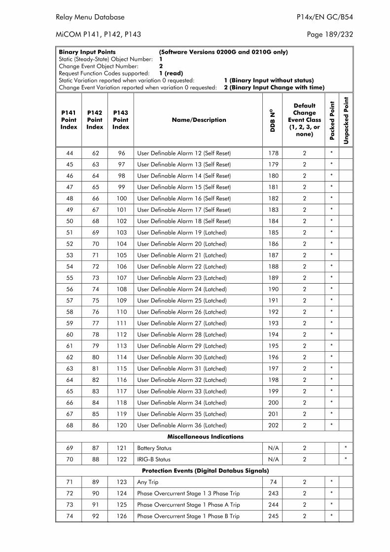
Relay Menu Database P14x/EN GC/B54
MiCOM P141, P142, P143 Page 189/232
Binary Input Points (Software Versions 0200G and 0210G only)Static (Steady-State) Object Number: 1Change Event Object Number: 2Request Function Codes supported: 1 (read)Static Variation reported when variation 0 requested: 1 (Binary Input without status)Change Event Variation reported when variation 0 requested: 2 (Binary Input Change with time)
P141PointIndex
P142PointIndex
P143PointIndex
Name/Description
DD
B N
O
DefaultChange
Event Class(1, 2, 3, or
none)
Pa
cked
Po
int
Un
pa
cked
Po
int
44 62 96 User Definable Alarm 12 (Self Reset) 178 2 *
45 63 97 User Definable Alarm 13 (Self Reset) 179 2 *
46 64 98 User Definable Alarm 14 (Self Reset) 180 2 *
47 65 99 User Definable Alarm 15 (Self Reset) 181 2 *
48 66 100 User Definable Alarm 16 (Self Reset) 182 2 *
49 67 101 User Definable Alarm 17 (Self Reset) 183 2 *
50 68 102 User Definable Alarm 18 (Self Reset) 184 2 *
51 69 103 User Definable Alarm 19 (Latched) 185 2 *
52 70 104 User Definable Alarm 20 (Latched) 186 2 *
53 71 105 User Definable Alarm 21 (Latched) 187 2 *
54 72 106 User Definable Alarm 22 (Latched) 188 2 *
55 73 107 User Definable Alarm 23 (Latched) 189 2 *
56 74 108 User Definable Alarm 24 (Latched) 190 2 *
57 75 109 User Definable Alarm 25 (Latched) 191 2 *
58 76 110 User Definable Alarm 26 (Latched) 192 2 *
59 77 111 User Definable Alarm 27 (Latched) 193 2 *
60 78 112 User Definable Alarm 28 (Latched) 194 2 *
61 79 113 User Definable Alarm 29 (Latched) 195 2 *
62 80 114 User Definable Alarm 30 (Latched) 196 2 *
63 81 115 User Definable Alarm 31 (Latched) 197 2 *
64 82 116 User Definable Alarm 32 (Latched) 198 2 *
65 83 117 User Definable Alarm 33 (Latched) 199 2 *
66 84 118 User Definable Alarm 34 (Latched) 200 2 *
67 85 119 User Definable Alarm 35 (Latched) 201 2 *
68 86 120 User Definable Alarm 36 (Latched) 202 2 *
Miscellaneous Indications
69 87 121 Battery Status N/A 2 *
70 88 122 IRIG-B Status N/A 2 *
Protection Events (Digital Databus Signals)
71 89 123 Any Trip 74 2 *
72 90 124 Phase Overcurrent Stage 1 3 Phase Trip 243 2 *
73 91 125 Phase Overcurrent Stage 1 Phase A Trip 244 2 *
74 92 126 Phase Overcurrent Stage 1 Phase B Trip 245 2 *
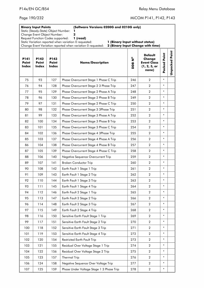
P14x/EN GC/B54 Relay Menu Database
Page 190/232 MiCOM P141, P142, P143
Binary Input Points (Software Versions 0200G and 0210G only)Static (Steady-State) Object Number: 1Change Event Object Number: 2Request Function Codes supported: 1 (read)Static Variation reported when variation 0 requested: 1 (Binary Input without status)Change Event Variation reported when variation 0 requested: 2 (Binary Input Change with time)
P141PointIndex
P142PointIndex
P143PointIndex
Name/Description
DD
B N
O
DefaultChange
Event Class(1, 2, 3, or
none)
Pa
cked
Po
int
Un
pa
cked
Po
int
75 93 127 Phase Overcurrent Stage 1 Phase C Trip 246 2 *
76 94 128 Phase Overcurrent Stage 2 3 Phase Trip 247 2 *
77 95 129 Phase Overcurrent Stage 2 Phase A Trip 248 2 *
78 96 130 Phase Overcurrent Stage 2 Phase B Trip 249 2 *
79 97 131 Phase Overcurrent Stage 2 Phase C Trip 250 2 *
80 98 132 Phase Overcurrent Stage 3 3Phase Trip 251 2 *
81 99 133 Phase Overcurrent Stage 3 Phase A Trip 252 2 *
82 100 134 Phase Overcurrent Stage 3 Phase B Trip 253 2 *
83 101 135 Phase Overcurrent Stage 3 Phase C Trip 254 2 *
84 102 136 Phase Overcurrent Stage 4 3Phase Trip 255 2 *
85 103 137 Phase Overcurrent Stage 4 Phase A Trip 256 2 *
86 104 138 Phase Overcurrent Stage 4 Phase B Trip 257 2 *
87 105 139 Phase Overcurrent Stage 4 Phase C Trip 258 2 *
88 106 140 Negative Sequence Overcurrent Trip 259 2 *
89 107 141 Broken Conductor Trip 260 2 *
90 108 142 Earth Fault 1 Stage 1 Trip 261 2 *
91 109 143 Earth Fault 1 Stage 2 Trip 262 2 *
92 110 144 Earth Fault 1 Stage 3 Trip 263 2 *
93 111 145 Earth Fault 1 Stage 4 Trip 264 2 *
94 112 146 Earth Fault 2 Stage 1 Trip 265 2 *
95 113 147 Earth Fault 2 Stage 2 Trip 266 2 *
96 114 148 Earth Fault 2 Stage 3 Trip 267 2 *
97 115 149 Earth Fault 2 Stage 4 Trip 268 2 *
98 116 150 Sensitive Earth Fault Stage 1 Trip 269 2 *
99 117 151 Sensitive Earth Fault Stage 2 Trip 270 2 *
100 118 152 Sensitive Earth Fault Stage 3 Trip 271 2 *
101 119 153 Sensitive Earth Fault Stage 4 Trip 272 2 *
102 120 154 Restricted Earth Fault Trip 273 2 *
103 121 155 Residual Over Voltage Stage 1 Trip 274 2 *
104 122 156 Residual Over Voltage Stage 2 Trip 275 2 *
105 123 157 Thermal Trip 276 2 *
106 124 158 Negative Sequence Over Voltage Trip 277 2 *
107 125 159 Phase Under Voltage Stage 1 3 Phase Trip 278 2 *
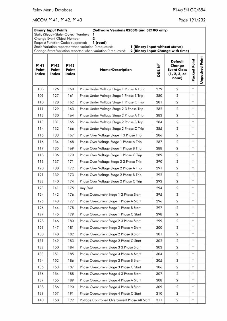
Relay Menu Database P14x/EN GC/B54
MiCOM P141, P142, P143 Page 191/232
Binary Input Points (Software Versions 0200G and 0210G only)Static (Steady-State) Object Number: 1Change Event Object Number: 2Request Function Codes supported: 1 (read)Static Variation reported when variation 0 requested: 1 (Binary Input without status)Change Event Variation reported when variation 0 requested: 2 (Binary Input Change with time)
P141PointIndex
P142PointIndex
P143PointIndex
Name/Description
DD
B N
O
DefaultChange
Event Class(1, 2, 3, or
none)
Pa
cked
Po
int
Un
pa
cked
Po
int
108 126 160 Phase Under Voltage Stage 1 Phase A Trip 279 2 *
109 127 161 Phase Under Voltage Stage 1 Phase B Trip 280 2 *
110 128 162 Phase Under Voltage Stage 1 Phase C Trip 281 2 *
111 129 163 Phase Under Voltage Stage 2 3 Phase Trip 282 2 *
112 130 164 Phase Under Voltage Stage 2 Phase A Trip 283 2 *
113 131 165 Phase Under Voltage Stage 2 Phase B Trip 284 2 *
114 132 166 Phase Under Voltage Stage 2 Phase C Trip 285 2 *
115 133 167 Phase Over Voltage Stage 1 3 Phase Trip 286 2 *
116 134 168 Phase Over Voltage Stage 1 Phase A Trip 287 2 *
117 135 169 Phase Over Voltage Stage 1 Phase B Trip 288 2 *
118 136 170 Phase Over Voltage Stage 1 Phase C Trip 289 2 *
119 137 171 Phase Over Voltage Stage 2 3 Phase Trip 290 2 *
120 138 172 Phase Over Voltage Stage 2 Phase A Trip 291 2 *
121 139 173 Phase Over Voltage Stage 2 Phase B Trip 292 2 *
122 140 174 Phase Over Voltage Stage 2 Phase C Trip 293 2 *
123 141 175 Any Start 294 2 *
124 142 176 Phase Overcurrent Stage 1 3 Phase Start 295 2 *
125 143 177 Phase Overcurrent Stage 1 Phase A Start 296 2 *
126 144 178 Phase Overcurrent Stage 1 Phase B Start 297 2 *
127 145 179 Phase Overcurrent Stage 1 Phase C Start 298 2 *
128 146 180 Phase Overcurrent Stage 2 3 Phase Start 299 2 *
129 147 181 Phase Overcurrent Stage 2 Phase A Start 300 2 *
130 148 182 Phase Overcurrent Stage 2 Phase B Start 301 2 *
131 149 183 Phase Overcurrent Stage 2 Phase C Start 302 2 *
132 150 184 Phase Overcurrent Stage 3 3 Phase Start 303 2 *
133 151 185 Phase Overcurrent Stage 3 Phase A Start 304 2 *
134 152 186 Phase Overcurrent Stage 3 Phase B Start 305 2 *
135 153 187 Phase Overcurrent Stage 3 Phase C Start 306 2 *
136 154 188 Phase Overcurrent Stage 4 3 Phase Start 307 2 *
137 155 189 Phase Overcurrent Stage 4 Phase A Start 308 2 *
138 156 190 Phase Overcurrent Stage 4 Phase B Start 309 2 *
139 157 191 Phase Overcurrent Stage 4 Phase C Start 310 2 *
140 158 192 Voltage Controlled Overcurrent Phase AB Start 311 2 *
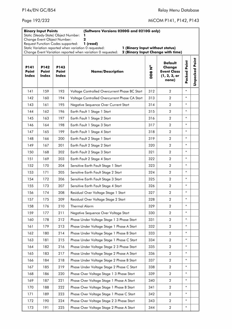
P14x/EN GC/B54 Relay Menu Database
Page 192/232 MiCOM P141, P142, P143
Binary Input Points (Software Versions 0200G and 0210G only)Static (Steady-State) Object Number: 1Change Event Object Number: 2Request Function Codes supported: 1 (read)Static Variation reported when variation 0 requested: 1 (Binary Input without status)Change Event Variation reported when variation 0 requested: 2 (Binary Input Change with time)
P141PointIndex
P142PointIndex
P143PointIndex
Name/Description
DD
B N
O
DefaultChange
Event Class(1, 2, 3, or
none)
Pa
cked
Po
int
Un
pa
cked
Po
int
141 159 193 Voltage Controlled Overcurrent Phase BC Start 312 2 *
142 160 194 Voltage Controlled Overcurrent Phase CA Start 313 2 *
143 161 195 Negative Sequence Over Current Start 314 2 *
144 162 196 Earth Fault 1 Stage 1 Start 315 2 *
145 163 197 Earth Fault 1 Stage 2 Start 316 2 *
146 164 198 Earth Fault 1 Stage 3 Start 317 2 *
147 165 199 Earth Fault 1 Stage 4 Start 318 2 *
148 166 200 Earth Fault 2 Stage 1 Start 319 2 *
149 167 201 Earth Fault 2 Stage 2 Start 320 2 *
150 168 202 Earth Fault 2 Stage 3 Start 321 2 *
151 169 203 Earth Fault 2 Stage 4 Start 322 2 *
152 170 204 Sensitive Earth Fault Stage 1 Start 323 2 *
153 171 205 Sensitive Earth Fault Stage 2 Start 324 2 *
154 172 206 Sensitive Earth Fault Stage 3 Start 325 2 *
155 173 207 Sensitive Earth Fault Stage 4 Start 326 2 *
156 174 208 Residual Over Voltage Stage 1 Start 327 2 *
157 175 209 Residual Over Voltage Stage 2 Start 328 2 *
158 176 210 Thermal Alarm 329 2 *
159 177 211 Negative Sequence Over Voltage Start 330 2 *
160 178 212 Phase Under Voltage Stage 1 3 Phase Start 331 2 *
161 179 213 Phase Under Voltage Stage 1 Phase A Start 332 2 *
162 180 214 Phase Under Voltage Stage 1 Phase B Start 333 2 *
163 181 215 Phase Under Voltage Stage 1 Phase C Start 334 2 *
164 182 216 Phase Under Voltage Stage 2 3 Phase Start 335 2 *
165 183 217 Phase Under Voltage Stage 2 Phase A Start 336 2 *
166 184 218 Phase Under Voltage Stage 2 Phase B Start 337 2 *
167 185 219 Phase Under Voltage Stage 2 Phase C Start 338 2 *
168 186 220 Phase Over Voltage Stage 1 3 Phase Start 339 2 *
169 187 221 Phase Over Voltage Stage 1 Phase A Start 340 2 *
170 188 222 Phase Over Voltage Stage 1 Phase B Start 341 2 *
171 189 223 Phase Over Voltage Stage 1 Phase C Start 342 2 *
172 190 224 Phase Over Voltage Stage 2 3 Phase Start 343 2 *
173 191 225 Phase Over Voltage Stage 2 Phase A Start 344 2 *
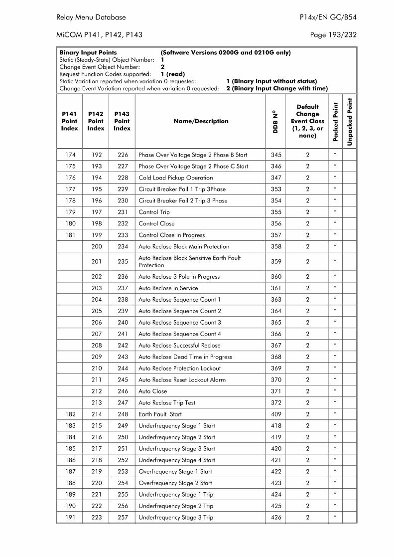
Relay Menu Database P14x/EN GC/B54
MiCOM P141, P142, P143 Page 193/232
Binary Input Points (Software Versions 0200G and 0210G only)Static (Steady-State) Object Number: 1Change Event Object Number: 2Request Function Codes supported: 1 (read)Static Variation reported when variation 0 requested: 1 (Binary Input without status)Change Event Variation reported when variation 0 requested: 2 (Binary Input Change with time)
P141PointIndex
P142PointIndex
P143PointIndex
Name/Description
DD
B N
O
DefaultChange
Event Class(1, 2, 3, or
none)
Pa
cked
Po
int
Un
pa
cked
Po
int
174 192 226 Phase Over Voltage Stage 2 Phase B Start 345 2 *
175 193 227 Phase Over Voltage Stage 2 Phase C Start 346 2 *
176 194 228 Cold Load Pickup Operation 347 2 *
177 195 229 Circuit Breaker Fail 1 Trip 3Phase 353 2 *
178 196 230 Circuit Breaker Fail 2 Trip 3 Phase 354 2 *
179 197 231 Control Trip 355 2 *
180 198 232 Control Close 356 2 *
181 199 233 Control Close in Progress 357 2 *
200 234 Auto Reclose Block Main Protection 358 2 *
201 235Auto Reclose Block Sensitive Earth FaultProtection
359 2 *
202 236 Auto Reclose 3 Pole in Progress 360 2 *
203 237 Auto Reclose in Service 361 2 *
204 238 Auto Reclose Sequence Count 1 363 2 *
205 239 Auto Reclose Sequence Count 2 364 2 *
206 240 Auto Reclose Sequence Count 3 365 2 *
207 241 Auto Reclose Sequence Count 4 366 2 *
208 242 Auto Reclose Successful Reclose 367 2 *
209 243 Auto Reclose Dead Time in Progress 368 2 *
210 244 Auto Reclose Protection Lockout 369 2 *
211 245 Auto Reclose Reset Lockout Alarm 370 2 *
212 246 Auto Close 371 2 *
213 247 Auto Reclose Trip Test 372 2 *
182 214 248 Earth Fault Start 409 2 *
183 215 249 Underfrequency Stage 1 Start 418 2 *
184 216 250 Underfrequency Stage 2 Start 419 2 *
185 217 251 Underfrequency Stage 3 Start 420 2 *
186 218 252 Underfrequency Stage 4 Start 421 2 *
187 219 253 Overfrequency Stage 1 Start 422 2 *
188 220 254 Overfrequency Stage 2 Start 423 2 *
189 221 255 Underfrequency Stage 1 Trip 424 2 *
190 222 256 Underfrequency Stage 2 Trip 425 2 *
191 223 257 Underfrequency Stage 3 Trip 426 2 *
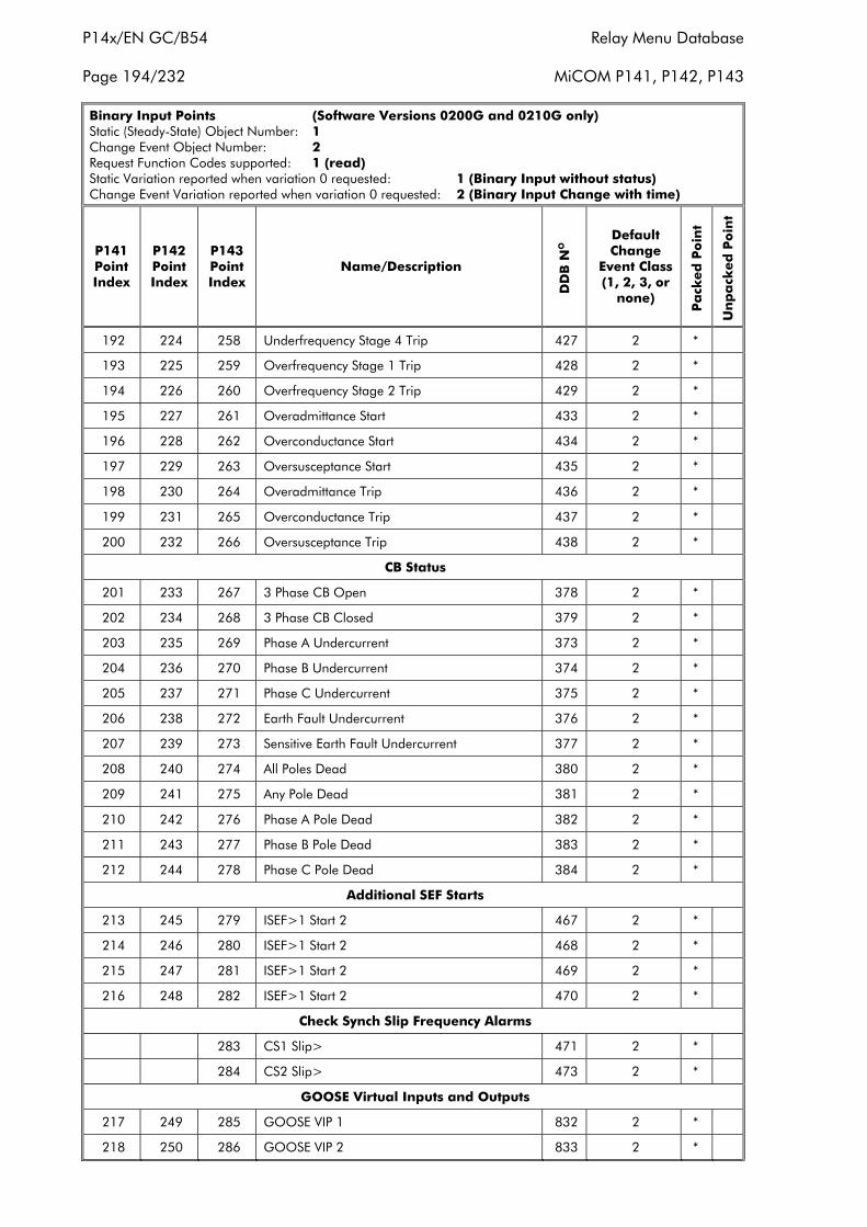
P14x/EN GC/B54 Relay Menu Database
Page 194/232 MiCOM P141, P142, P143
Binary Input Points (Software Versions 0200G and 0210G only)Static (Steady-State) Object Number: 1Change Event Object Number: 2Request Function Codes supported: 1 (read)Static Variation reported when variation 0 requested: 1 (Binary Input without status)Change Event Variation reported when variation 0 requested: 2 (Binary Input Change with time)
P141PointIndex
P142PointIndex
P143PointIndex
Name/Description
DD
B N
O
DefaultChange
Event Class(1, 2, 3, or
none)
Pa
cked
Po
int
Un
pa
cked
Po
int
192 224 258 Underfrequency Stage 4 Trip 427 2 *
193 225 259 Overfrequency Stage 1 Trip 428 2 *
194 226 260 Overfrequency Stage 2 Trip 429 2 *
195 227 261 Overadmittance Start 433 2 *
196 228 262 Overconductance Start 434 2 *
197 229 263 Oversusceptance Start 435 2 *
198 230 264 Overadmittance Trip 436 2 *
199 231 265 Overconductance Trip 437 2 *
200 232 266 Oversusceptance Trip 438 2 *
CB Status
201 233 267 3 Phase CB Open 378 2 *
202 234 268 3 Phase CB Closed 379 2 *
203 235 269 Phase A Undercurrent 373 2 *
204 236 270 Phase B Undercurrent 374 2 *
205 237 271 Phase C Undercurrent 375 2 *
206 238 272 Earth Fault Undercurrent 376 2 *
207 239 273 Sensitive Earth Fault Undercurrent 377 2 *
208 240 274 All Poles Dead 380 2 *
209 241 275 Any Pole Dead 381 2 *
210 242 276 Phase A Pole Dead 382 2 *
211 243 277 Phase B Pole Dead 383 2 *
212 244 278 Phase C Pole Dead 384 2 *
Additional SEF Starts
213 245 279 ISEF>1 Start 2 467 2 *
214 246 280 ISEF>1 Start 2 468 2 *
215 247 281 ISEF>1 Start 2 469 2 *
216 248 282 ISEF>1 Start 2 470 2 *
Check Synch Slip Frequency Alarms
283 CS1 Slip> 471 2 *
284 CS2 Slip> 473 2 *
GOOSE Virtual Inputs and Outputs
217 249 285 GOOSE VIP 1 832 2 *
218 250 286 GOOSE VIP 2 833 2 *
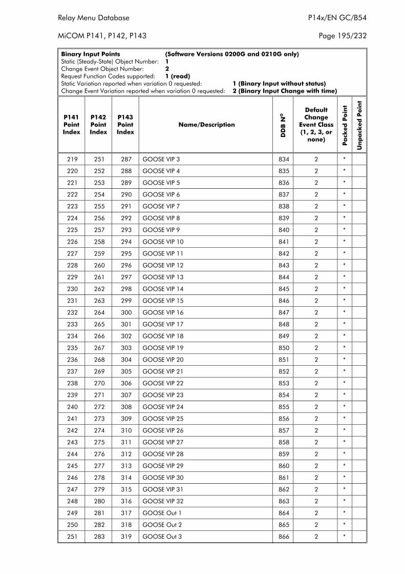
Relay Menu Database P14x/EN GC/B54
MiCOM P141, P142, P143 Page 195/232
Binary Input Points (Software Versions 0200G and 0210G only)Static (Steady-State) Object Number: 1Change Event Object Number: 2Request Function Codes supported: 1 (read)Static Variation reported when variation 0 requested: 1 (Binary Input without status)Change Event Variation reported when variation 0 requested: 2 (Binary Input Change with time)
P141PointIndex
P142PointIndex
P143PointIndex
Name/Description
DD
B N
O
DefaultChange
Event Class(1, 2, 3, or
none)
Pa
cked
Po
int
Un
pa
cked
Po
int
219 251 287 GOOSE VIP 3 834 2 *
220 252 288 GOOSE VIP 4 835 2 *
221 253 289 GOOSE VIP 5 836 2 *
222 254 290 GOOSE VIP 6 837 2 *
223 255 291 GOOSE VIP 7 838 2 *
224 256 292 GOOSE VIP 8 839 2 *
225 257 293 GOOSE VIP 9 840 2 *
226 258 294 GOOSE VIP 10 841 2 *
227 259 295 GOOSE VIP 11 842 2 *
228 260 296 GOOSE VIP 12 843 2 *
229 261 297 GOOSE VIP 13 844 2 *
230 262 298 GOOSE VIP 14 845 2 *
231 263 299 GOOSE VIP 15 846 2 *
232 264 300 GOOSE VIP 16 847 2 *
233 265 301 GOOSE VIP 17 848 2 *
234 266 302 GOOSE VIP 18 849 2 *
235 267 303 GOOSE VIP 19 850 2 *
236 268 304 GOOSE VIP 20 851 2 *
237 269 305 GOOSE VIP 21 852 2 *
238 270 306 GOOSE VIP 22 853 2 *
239 271 307 GOOSE VIP 23 854 2 *
240 272 308 GOOSE VIP 24 855 2 *
241 273 309 GOOSE VIP 25 856 2 *
242 274 310 GOOSE VIP 26 857 2 *
243 275 311 GOOSE VIP 27 858 2 *
244 276 312 GOOSE VIP 28 859 2 *
245 277 313 GOOSE VIP 29 860 2 *
246 278 314 GOOSE VIP 30 861 2 *
247 279 315 GOOSE VIP 31 862 2 *
248 280 316 GOOSE VIP 32 863 2 *
249 281 317 GOOSE Out 1 864 2 *
250 282 318 GOOSE Out 2 865 2 *
251 283 319 GOOSE Out 3 866 2 *
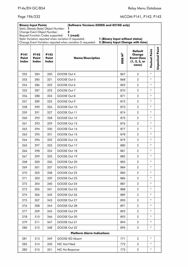
P14x/EN GC/B54 Relay Menu Database
Page 196/232 MiCOM P141, P142, P143
Binary Input Points (Software Versions 0200G and 0210G only)Static (Steady-State) Object Number: 1Change Event Object Number: 2Request Function Codes supported: 1 (read)Static Variation reported when variation 0 requested: 1 (Binary Input without status)Change Event Variation reported when variation 0 requested: 2 (Binary Input Change with time)
P141PointIndex
P142PointIndex
P143PointIndex
Name/Description
DD
B N
O
DefaultChange
Event Class(1, 2, 3, or
none)
Pa
cked
Po
int
Un
pa
cked
Po
int
252 284 320 GOOSE Out 4 867 2 *
253 285 321 GOOSE Out 5 868 2 *
254 286 322 GOOSE Out 6 869 2 *
255 287 323 GOOSE Out 7 870 2 *
256 288 324 GOOSE Out 8 871 2 *
257 289 325 GOOSE Out 9 872 2 *
258 290 326 GOOSE Out 10 873 2 *
259 291 327 GOOSE Out 11 874 2 *
260 292 328 GOOSE Out 12 875 2 *
261 293 329 GOOSE Out 13 876 2 *
262 294 330 GOOSE Out 14 877 2 *
263 295 331 GOOSE Out 15 878 2 *
264 296 332 GOOSE Out 16 879 2 *
265 297 333 GOOSE Out 17 880 2 *
266 298 334 GOOSE Out 18 881 2 *
267 299 335 GOOSE Out 19 882 2 *
268 300 336 GOOSE Out 20 883 2 *
269 301 337 GOOSE Out 21 884 2 *
270 302 338 GOOSE Out 22 885 2 *
271 303 339 GOOSE Out 23 886 2 *
272 304 340 GOOSE Out 24 887 2 *
273 305 341 GOOSE Out 25 888 2 *
274 306 342 GOOSE Out 26 889 2 *
275 307 343 GOOSE Out 27 890 2 *
276 308 344 GOOSE Out 28 891 2 *
277 309 345 GOOSE Out 29 892 2 *
278 310 346 GOOSE Out 30 893 2 *
279 311 347 GOOSE Out 31 894 2 *
280 312 348 GOOSE Out 32 895 2 *
Platform Alarm Indications
281 313 349 GOOSE IED Absent 771 2 *
282 314 350 NIC Not Fitted 772 2 *
283 315 351 NIC No Response 773 2 *
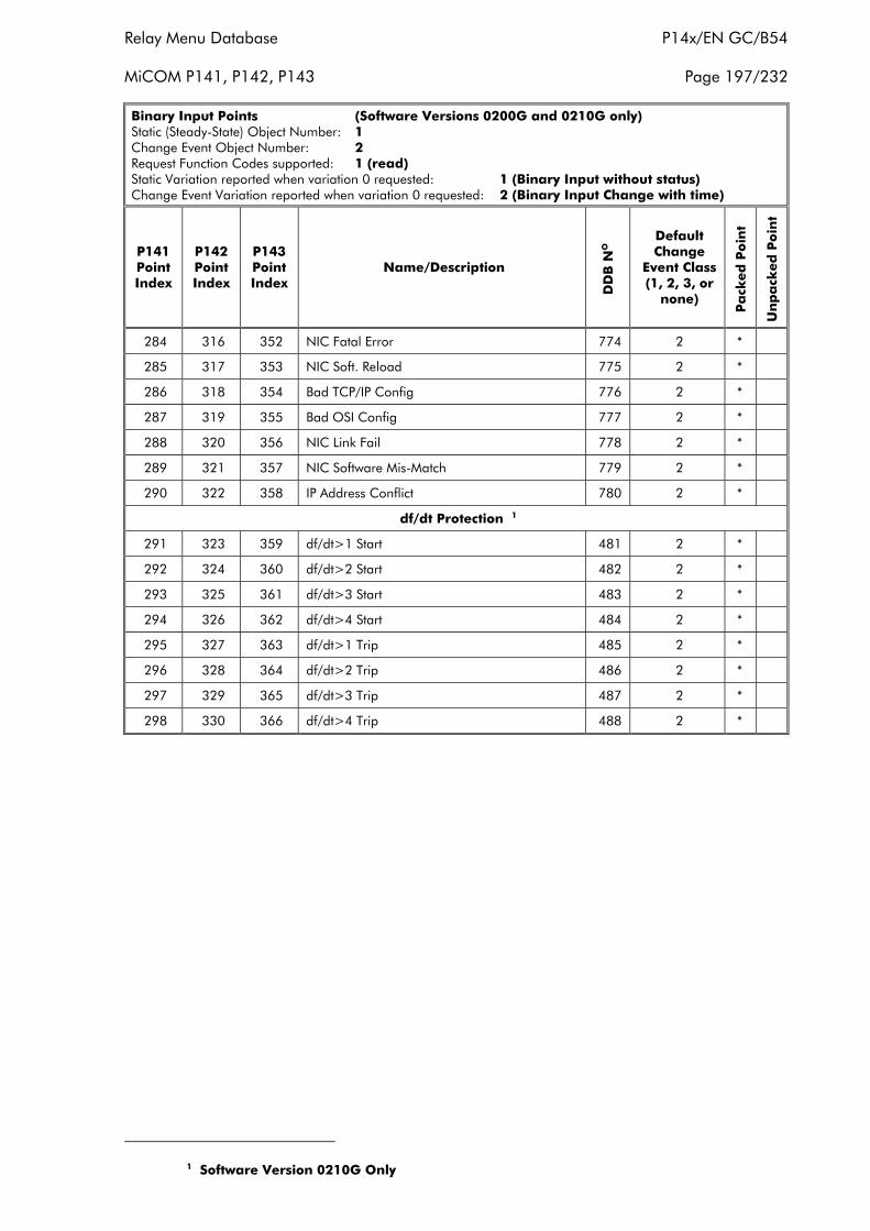
Relay Menu Database P14x/EN GC/B54
MiCOM P141, P142, P143 Page 197/232
Binary Input Points (Software Versions 0200G and 0210G only)Static (Steady-State) Object Number: 1Change Event Object Number: 2Request Function Codes supported: 1 (read)Static Variation reported when variation 0 requested: 1 (Binary Input without status)Change Event Variation reported when variation 0 requested: 2 (Binary Input Change with time)
P141PointIndex
P142PointIndex
P143PointIndex
Name/Description
DD
B N
O
DefaultChange
Event Class(1, 2, 3, or
none)
Pa
cked
Po
int
Un
pa
cked
Po
int
284 316 352 NIC Fatal Error 774 2 *
285 317 353 NIC Soft. Reload 775 2 *
286 318 354 Bad TCP/IP Config 776 2 *
287 319 355 Bad OSI Config 777 2 *
288 320 356 NIC Link Fail 778 2 *
289 321 357 NIC Software Mis-Match 779 2 *
290 322 358 IP Address Conflict 780 2 *
df/dt Protection 1
291 323 359 df/dt>1 Start 481 2 *
292 324 360 df/dt>2 Start 482 2 *
293 325 361 df/dt>3 Start 483 2 *
294 326 362 df/dt>4 Start 484 2 *
295 327 363 df/dt>1 Trip 485 2 *
296 328 364 df/dt>2 Trip 486 2 *
297 329 365 df/dt>3 Trip 487 2 *
298 330 366 df/dt>4 Trip 488 2 *
1 Software Version 0210G Only
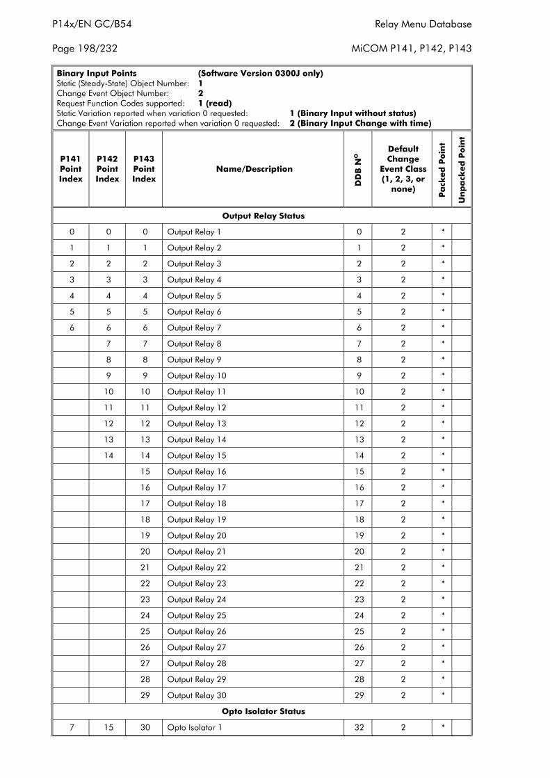
P14x/EN GC/B54 Relay Menu Database
Page 198/232 MiCOM P141, P142, P143
Binary Input Points (Software Version 0300J only)Static (Steady-State) Object Number: 1Change Event Object Number: 2Request Function Codes supported: 1 (read)Static Variation reported when variation 0 requested: 1 (Binary Input without status)Change Event Variation reported when variation 0 requested: 2 (Binary Input Change with time)
P141PointIndex
P142PointIndex
P143PointIndex
Name/Description
DD
B N
O
DefaultChange
Event Class(1, 2, 3, or
none)
Pa
cked
Po
int
Un
pa
cked
Po
int
Output Relay Status
0 0 0 Output Relay 1 0 2 *
1 1 1 Output Relay 2 1 2 *
2 2 2 Output Relay 3 2 2 *
3 3 3 Output Relay 4 3 2 *
4 4 4 Output Relay 5 4 2 *
5 5 5 Output Relay 6 5 2 *
6 6 6 Output Relay 7 6 2 *
7 7 Output Relay 8 7 2 *
8 8 Output Relay 9 8 2 *
9 9 Output Relay 10 9 2 *
10 10 Output Relay 11 10 2 *
11 11 Output Relay 12 11 2 *
12 12 Output Relay 13 12 2 *
13 13 Output Relay 14 13 2 *
14 14 Output Relay 15 14 2 *
15 Output Relay 16 15 2 *
16 Output Relay 17 16 2 *
17 Output Relay 18 17 2 *
18 Output Relay 19 18 2 *
19 Output Relay 20 19 2 *
20 Output Relay 21 20 2 *
21 Output Relay 22 21 2 *
22 Output Relay 23 22 2 *
23 Output Relay 24 23 2 *
24 Output Relay 25 24 2 *
25 Output Relay 26 25 2 *
26 Output Relay 27 26 2 *
27 Output Relay 28 27 2 *
28 Output Relay 29 28 2 *
29 Output Relay 30 29 2 *
Opto Isolator Status
7 15 30 Opto Isolator 1 32 2 *
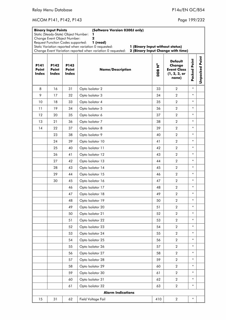
Relay Menu Database P14x/EN GC/B54
MiCOM P141, P142, P143 Page 199/232
Binary Input Points (Software Version 0300J only)Static (Steady-State) Object Number: 1Change Event Object Number: 2Request Function Codes supported: 1 (read)Static Variation reported when variation 0 requested: 1 (Binary Input without status)Change Event Variation reported when variation 0 requested: 2 (Binary Input Change with time)
P141PointIndex
P142PointIndex
P143PointIndex
Name/Description
DD
B N
O
DefaultChange
Event Class(1, 2, 3, or
none)
Pa
cked
Po
int
Un
pa
cked
Po
int
8 16 31 Opto Isolator 2 33 2 *
9 17 32 Opto Isolator 3 34 2 *
10 18 33 Opto Isolator 4 35 2 *
11 19 34 Opto Isolator 5 36 2 *
12 20 35 Opto Isolator 6 37 2 *
13 21 36 Opto Isolator 7 38 2 *
14 22 37 Opto Isolator 8 39 2 *
23 38 Opto Isolator 9 40 2 *
24 39 Opto Isolator 10 41 2 *
25 40 Opto Isolator 11 42 2 *
26 41 Opto Isolator 12 43 2 *
27 42 Opto Isolator 13 44 2 *
28 43 Opto Isolator 14 45 2 *
29 44 Opto Isolator 15 46 2 *
30 45 Opto Isolator 16 47 2 *
46 Opto Isolator 17 48 2 *
47 Opto Isolator 18 49 2 *
48 Opto Isolator 19 50 2 *
49 Opto Isolator 20 51 2 *
50 Opto Isolator 21 52 2 *
51 Opto Isolator 22 53 2 *
52 Opto Isolator 23 54 2 *
53 Opto Isolator 24 55 2 *
54 Opto Isolator 25 56 2 *
55 Opto Isolator 26 57 2 *
56 Opto Isolator 27 58 2 *
57 Opto Isolator 28 59 2 *
58 Opto Isolator 29 60 2 *
59 Opto Isolator 30 61 2 *
60 Opto Isolator 31 62 2 *
61 Opto Isolator 32 63 2 *
Alarm Indications
15 31 62 Field Voltage Fail 410 2 *
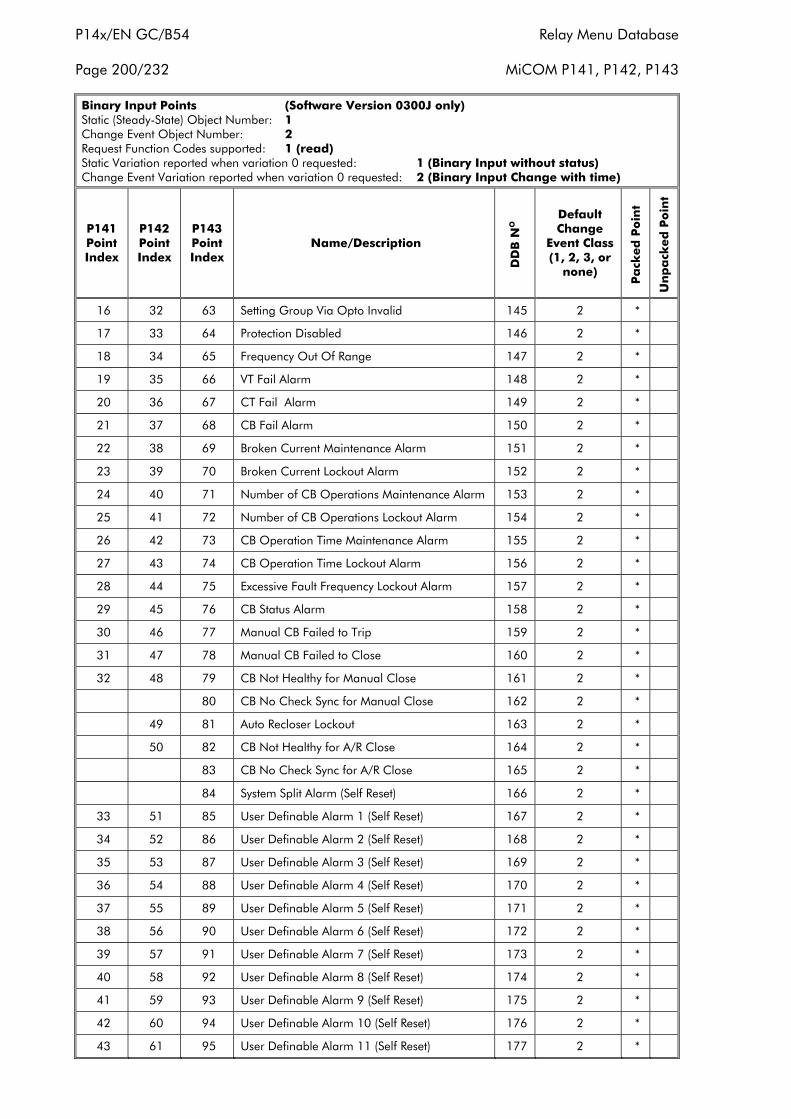
P14x/EN GC/B54 Relay Menu Database
Page 200/232 MiCOM P141, P142, P143
Binary Input Points (Software Version 0300J only)Static (Steady-State) Object Number: 1Change Event Object Number: 2Request Function Codes supported: 1 (read)Static Variation reported when variation 0 requested: 1 (Binary Input without status)Change Event Variation reported when variation 0 requested: 2 (Binary Input Change with time)
P141PointIndex
P142PointIndex
P143PointIndex
Name/Description
DD
B N
O
DefaultChange
Event Class(1, 2, 3, or
none)
Pa
cked
Po
int
Un
pa
cked
Po
int
16 32 63 Setting Group Via Opto Invalid 145 2 *
17 33 64 Protection Disabled 146 2 *
18 34 65 Frequency Out Of Range 147 2 *
19 35 66 VT Fail Alarm 148 2 *
20 36 67 CT Fail Alarm 149 2 *
21 37 68 CB Fail Alarm 150 2 *
22 38 69 Broken Current Maintenance Alarm 151 2 *
23 39 70 Broken Current Lockout Alarm 152 2 *
24 40 71 Number of CB Operations Maintenance Alarm 153 2 *
25 41 72 Number of CB Operations Lockout Alarm 154 2 *
26 42 73 CB Operation Time Maintenance Alarm 155 2 *
27 43 74 CB Operation Time Lockout Alarm 156 2 *
28 44 75 Excessive Fault Frequency Lockout Alarm 157 2 *
29 45 76 CB Status Alarm 158 2 *
30 46 77 Manual CB Failed to Trip 159 2 *
31 47 78 Manual CB Failed to Close 160 2 *
32 48 79 CB Not Healthy for Manual Close 161 2 *
80 CB No Check Sync for Manual Close 162 2 *
49 81 Auto Recloser Lockout 163 2 *
50 82 CB Not Healthy for A/R Close 164 2 *
83 CB No Check Sync for A/R Close 165 2 *
84 System Split Alarm (Self Reset) 166 2 *
33 51 85 User Definable Alarm 1 (Self Reset) 167 2 *
34 52 86 User Definable Alarm 2 (Self Reset) 168 2 *
35 53 87 User Definable Alarm 3 (Self Reset) 169 2 *
36 54 88 User Definable Alarm 4 (Self Reset) 170 2 *
37 55 89 User Definable Alarm 5 (Self Reset) 171 2 *
38 56 90 User Definable Alarm 6 (Self Reset) 172 2 *
39 57 91 User Definable Alarm 7 (Self Reset) 173 2 *
40 58 92 User Definable Alarm 8 (Self Reset) 174 2 *
41 59 93 User Definable Alarm 9 (Self Reset) 175 2 *
42 60 94 User Definable Alarm 10 (Self Reset) 176 2 *
43 61 95 User Definable Alarm 11 (Self Reset) 177 2 *

Relay Menu Database P14x/EN GC/B54
MiCOM P141, P142, P143 Page 201/232
Binary Input Points (Software Version 0300J only)Static (Steady-State) Object Number: 1Change Event Object Number: 2Request Function Codes supported: 1 (read)Static Variation reported when variation 0 requested: 1 (Binary Input without status)Change Event Variation reported when variation 0 requested: 2 (Binary Input Change with time)
P141PointIndex
P142PointIndex
P143PointIndex
Name/Description
DD
B N
O
DefaultChange
Event Class(1, 2, 3, or
none)
Pa
cked
Po
int
Un
pa
cked
Po
int
44 62 96 User Definable Alarm 12 (Self Reset) 178 2 *
45 63 97 User Definable Alarm 13 (Self Reset) 179 2 *
46 64 98 User Definable Alarm 14 (Self Reset) 180 2 *
47 65 99 User Definable Alarm 15 (Self Reset) 181 2 *
48 66 100 User Definable Alarm 16 (Self Reset) 182 2 *
49 67 101 User Definable Alarm 17 (Self Reset) 183 2 *
50 68 102 User Definable Alarm 18 (Self Reset) 184 2 *
51 69 103 User Definable Alarm 19 (Latched) 185 2 *
52 70 104 User Definable Alarm 20 (Latched) 186 2 *
53 71 105 User Definable Alarm 21 (Latched) 187 2 *
54 72 106 User Definable Alarm 22 (Latched) 188 2 *
55 73 107 User Definable Alarm 23 (Latched) 189 2 *
56 74 108 User Definable Alarm 24 (Latched) 190 2 *
57 75 109 User Definable Alarm 25 (Latched) 191 2 *
58 76 110 User Definable Alarm 26 (Latched) 192 2 *
59 77 111 User Definable Alarm 27 (Latched) 193 2 *
60 78 112 User Definable Alarm 28 (Latched) 194 2 *
61 79 113 User Definable Alarm 29 (Latched) 195 2 *
62 80 114 User Definable Alarm 30 (Latched) 196 2 *
63 81 115 User Definable Alarm 31 (Latched) 197 2 *
64 82 116 User Definable Alarm 32 (Latched) 198 2 *
65 83 117 User Definable Alarm 33 (Latched) 199 2 *
66 84 118 User Definable Alarm 34 (Latched) 200 2 *
67 85 119 User Definable Alarm 35 (Latched) 201 2 *
68 86 120 User Definable Alarm 36 (Latched) 202 2 *
Miscellaneous Indications
69 87 121 Battery Status N/A 2 *
70 88 122 IRIG-B Status N/A 2 *
Protection Events (Digital Databus Signals)
71 89 123 Any Trip 74 2 *
72 90 124 Phase Overcurrent Stage 1 3 Phase Trip 243 2 *
73 91 125 Phase Overcurrent Stage 1 Phase A Trip 244 2 *
74 92 126 Phase Overcurrent Stage 1 Phase B Trip 245 2 *
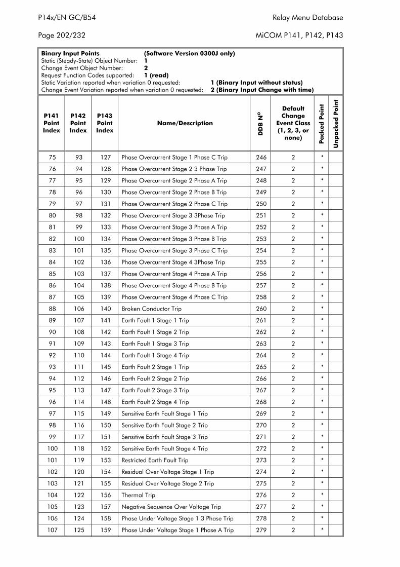
P14x/EN GC/B54 Relay Menu Database
Page 202/232 MiCOM P141, P142, P143
Binary Input Points (Software Version 0300J only)Static (Steady-State) Object Number: 1Change Event Object Number: 2Request Function Codes supported: 1 (read)Static Variation reported when variation 0 requested: 1 (Binary Input without status)Change Event Variation reported when variation 0 requested: 2 (Binary Input Change with time)
P141PointIndex
P142PointIndex
P143PointIndex
Name/Description
DD
B N
O
DefaultChange
Event Class(1, 2, 3, or
none)
Pa
cked
Po
int
Un
pa
cked
Po
int
75 93 127 Phase Overcurrent Stage 1 Phase C Trip 246 2 *
76 94 128 Phase Overcurrent Stage 2 3 Phase Trip 247 2 *
77 95 129 Phase Overcurrent Stage 2 Phase A Trip 248 2 *
78 96 130 Phase Overcurrent Stage 2 Phase B Trip 249 2 *
79 97 131 Phase Overcurrent Stage 2 Phase C Trip 250 2 *
80 98 132 Phase Overcurrent Stage 3 3Phase Trip 251 2 *
81 99 133 Phase Overcurrent Stage 3 Phase A Trip 252 2 *
82 100 134 Phase Overcurrent Stage 3 Phase B Trip 253 2 *
83 101 135 Phase Overcurrent Stage 3 Phase C Trip 254 2 *
84 102 136 Phase Overcurrent Stage 4 3Phase Trip 255 2 *
85 103 137 Phase Overcurrent Stage 4 Phase A Trip 256 2 *
86 104 138 Phase Overcurrent Stage 4 Phase B Trip 257 2 *
87 105 139 Phase Overcurrent Stage 4 Phase C Trip 258 2 *
88 106 140 Broken Conductor Trip 260 2 *
89 107 141 Earth Fault 1 Stage 1 Trip 261 2 *
90 108 142 Earth Fault 1 Stage 2 Trip 262 2 *
91 109 143 Earth Fault 1 Stage 3 Trip 263 2 *
92 110 144 Earth Fault 1 Stage 4 Trip 264 2 *
93 111 145 Earth Fault 2 Stage 1 Trip 265 2 *
94 112 146 Earth Fault 2 Stage 2 Trip 266 2 *
95 113 147 Earth Fault 2 Stage 3 Trip 267 2 *
96 114 148 Earth Fault 2 Stage 4 Trip 268 2 *
97 115 149 Sensitive Earth Fault Stage 1 Trip 269 2 *
98 116 150 Sensitive Earth Fault Stage 2 Trip 270 2 *
99 117 151 Sensitive Earth Fault Stage 3 Trip 271 2 *
100 118 152 Sensitive Earth Fault Stage 4 Trip 272 2 *
101 119 153 Restricted Earth Fault Trip 273 2 *
102 120 154 Residual Over Voltage Stage 1 Trip 274 2 *
103 121 155 Residual Over Voltage Stage 2 Trip 275 2 *
104 122 156 Thermal Trip 276 2 *
105 123 157 Negative Sequence Over Voltage Trip 277 2 *
106 124 158 Phase Under Voltage Stage 1 3 Phase Trip 278 2 *
107 125 159 Phase Under Voltage Stage 1 Phase A Trip 279 2 *
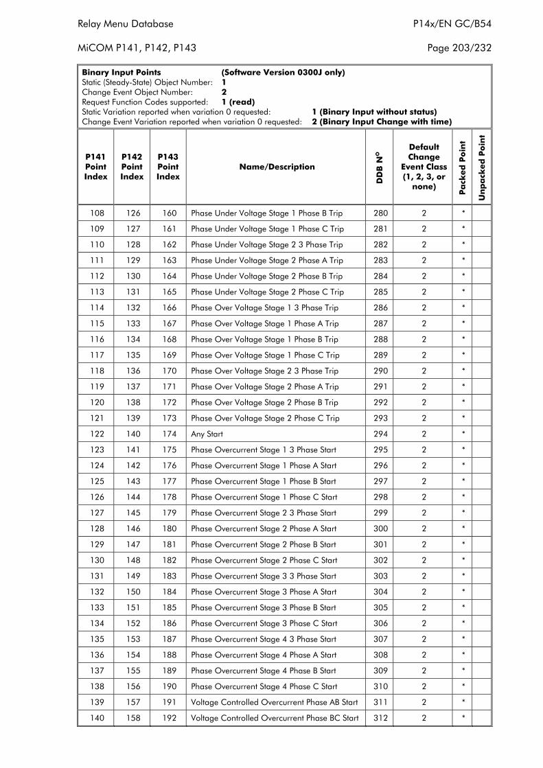
Relay Menu Database P14x/EN GC/B54
MiCOM P141, P142, P143 Page 203/232
Binary Input Points (Software Version 0300J only)Static (Steady-State) Object Number: 1Change Event Object Number: 2Request Function Codes supported: 1 (read)Static Variation reported when variation 0 requested: 1 (Binary Input without status)Change Event Variation reported when variation 0 requested: 2 (Binary Input Change with time)
P141PointIndex
P142PointIndex
P143PointIndex
Name/Description
DD
B N
O
DefaultChange
Event Class(1, 2, 3, or
none)
Pa
cked
Po
int
Un
pa
cked
Po
int
108 126 160 Phase Under Voltage Stage 1 Phase B Trip 280 2 *
109 127 161 Phase Under Voltage Stage 1 Phase C Trip 281 2 *
110 128 162 Phase Under Voltage Stage 2 3 Phase Trip 282 2 *
111 129 163 Phase Under Voltage Stage 2 Phase A Trip 283 2 *
112 130 164 Phase Under Voltage Stage 2 Phase B Trip 284 2 *
113 131 165 Phase Under Voltage Stage 2 Phase C Trip 285 2 *
114 132 166 Phase Over Voltage Stage 1 3 Phase Trip 286 2 *
115 133 167 Phase Over Voltage Stage 1 Phase A Trip 287 2 *
116 134 168 Phase Over Voltage Stage 1 Phase B Trip 288 2 *
117 135 169 Phase Over Voltage Stage 1 Phase C Trip 289 2 *
118 136 170 Phase Over Voltage Stage 2 3 Phase Trip 290 2 *
119 137 171 Phase Over Voltage Stage 2 Phase A Trip 291 2 *
120 138 172 Phase Over Voltage Stage 2 Phase B Trip 292 2 *
121 139 173 Phase Over Voltage Stage 2 Phase C Trip 293 2 *
122 140 174 Any Start 294 2 *
123 141 175 Phase Overcurrent Stage 1 3 Phase Start 295 2 *
124 142 176 Phase Overcurrent Stage 1 Phase A Start 296 2 *
125 143 177 Phase Overcurrent Stage 1 Phase B Start 297 2 *
126 144 178 Phase Overcurrent Stage 1 Phase C Start 298 2 *
127 145 179 Phase Overcurrent Stage 2 3 Phase Start 299 2 *
128 146 180 Phase Overcurrent Stage 2 Phase A Start 300 2 *
129 147 181 Phase Overcurrent Stage 2 Phase B Start 301 2 *
130 148 182 Phase Overcurrent Stage 2 Phase C Start 302 2 *
131 149 183 Phase Overcurrent Stage 3 3 Phase Start 303 2 *
132 150 184 Phase Overcurrent Stage 3 Phase A Start 304 2 *
133 151 185 Phase Overcurrent Stage 3 Phase B Start 305 2 *
134 152 186 Phase Overcurrent Stage 3 Phase C Start 306 2 *
135 153 187 Phase Overcurrent Stage 4 3 Phase Start 307 2 *
136 154 188 Phase Overcurrent Stage 4 Phase A Start 308 2 *
137 155 189 Phase Overcurrent Stage 4 Phase B Start 309 2 *
138 156 190 Phase Overcurrent Stage 4 Phase C Start 310 2 *
139 157 191 Voltage Controlled Overcurrent Phase AB Start 311 2 *
140 158 192 Voltage Controlled Overcurrent Phase BC Start 312 2 *
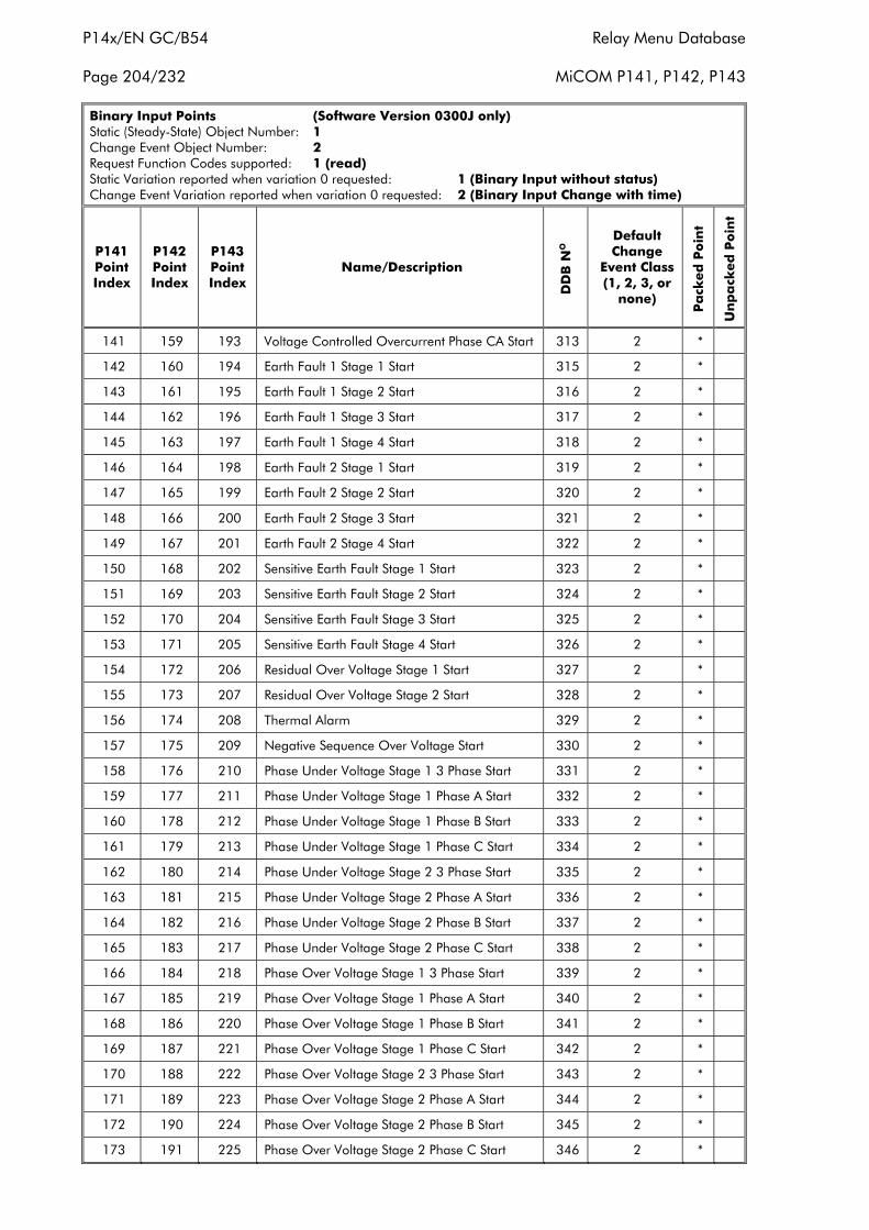
P14x/EN GC/B54 Relay Menu Database
Page 204/232 MiCOM P141, P142, P143
Binary Input Points (Software Version 0300J only)Static (Steady-State) Object Number: 1Change Event Object Number: 2Request Function Codes supported: 1 (read)Static Variation reported when variation 0 requested: 1 (Binary Input without status)Change Event Variation reported when variation 0 requested: 2 (Binary Input Change with time)
P141PointIndex
P142PointIndex
P143PointIndex
Name/Description
DD
B N
O
DefaultChange
Event Class(1, 2, 3, or
none)
Pa
cked
Po
int
Un
pa
cked
Po
int
141 159 193 Voltage Controlled Overcurrent Phase CA Start 313 2 *
142 160 194 Earth Fault 1 Stage 1 Start 315 2 *
143 161 195 Earth Fault 1 Stage 2 Start 316 2 *
144 162 196 Earth Fault 1 Stage 3 Start 317 2 *
145 163 197 Earth Fault 1 Stage 4 Start 318 2 *
146 164 198 Earth Fault 2 Stage 1 Start 319 2 *
147 165 199 Earth Fault 2 Stage 2 Start 320 2 *
148 166 200 Earth Fault 2 Stage 3 Start 321 2 *
149 167 201 Earth Fault 2 Stage 4 Start 322 2 *
150 168 202 Sensitive Earth Fault Stage 1 Start 323 2 *
151 169 203 Sensitive Earth Fault Stage 2 Start 324 2 *
152 170 204 Sensitive Earth Fault Stage 3 Start 325 2 *
153 171 205 Sensitive Earth Fault Stage 4 Start 326 2 *
154 172 206 Residual Over Voltage Stage 1 Start 327 2 *
155 173 207 Residual Over Voltage Stage 2 Start 328 2 *
156 174 208 Thermal Alarm 329 2 *
157 175 209 Negative Sequence Over Voltage Start 330 2 *
158 176 210 Phase Under Voltage Stage 1 3 Phase Start 331 2 *
159 177 211 Phase Under Voltage Stage 1 Phase A Start 332 2 *
160 178 212 Phase Under Voltage Stage 1 Phase B Start 333 2 *
161 179 213 Phase Under Voltage Stage 1 Phase C Start 334 2 *
162 180 214 Phase Under Voltage Stage 2 3 Phase Start 335 2 *
163 181 215 Phase Under Voltage Stage 2 Phase A Start 336 2 *
164 182 216 Phase Under Voltage Stage 2 Phase B Start 337 2 *
165 183 217 Phase Under Voltage Stage 2 Phase C Start 338 2 *
166 184 218 Phase Over Voltage Stage 1 3 Phase Start 339 2 *
167 185 219 Phase Over Voltage Stage 1 Phase A Start 340 2 *
168 186 220 Phase Over Voltage Stage 1 Phase B Start 341 2 *
169 187 221 Phase Over Voltage Stage 1 Phase C Start 342 2 *
170 188 222 Phase Over Voltage Stage 2 3 Phase Start 343 2 *
171 189 223 Phase Over Voltage Stage 2 Phase A Start 344 2 *
172 190 224 Phase Over Voltage Stage 2 Phase B Start 345 2 *
173 191 225 Phase Over Voltage Stage 2 Phase C Start 346 2 *
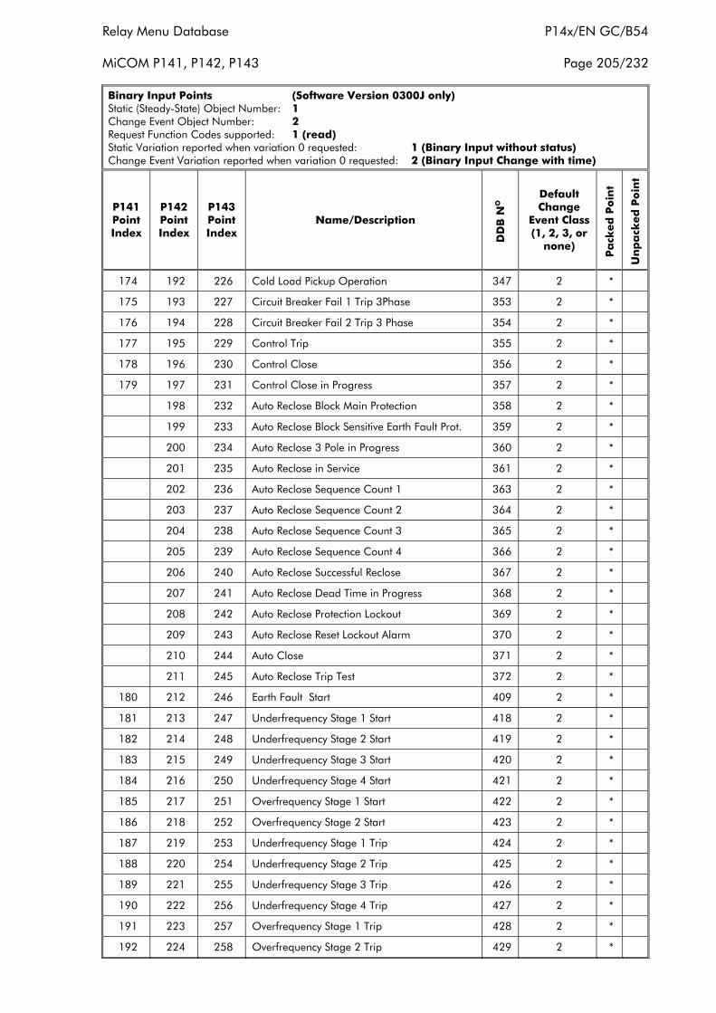
Relay Menu Database P14x/EN GC/B54
MiCOM P141, P142, P143 Page 205/232
Binary Input Points (Software Version 0300J only)Static (Steady-State) Object Number: 1Change Event Object Number: 2Request Function Codes supported: 1 (read)Static Variation reported when variation 0 requested: 1 (Binary Input without status)Change Event Variation reported when variation 0 requested: 2 (Binary Input Change with time)
P141PointIndex
P142PointIndex
P143PointIndex
Name/Description
DD
B N
O
DefaultChange
Event Class(1, 2, 3, or
none)
Pa
cked
Po
int
Un
pa
cked
Po
int
174 192 226 Cold Load Pickup Operation 347 2 *
175 193 227 Circuit Breaker Fail 1 Trip 3Phase 353 2 *
176 194 228 Circuit Breaker Fail 2 Trip 3 Phase 354 2 *
177 195 229 Control Trip 355 2 *
178 196 230 Control Close 356 2 *
179 197 231 Control Close in Progress 357 2 *
198 232 Auto Reclose Block Main Protection 358 2 *
199 233 Auto Reclose Block Sensitive Earth Fault Prot. 359 2 *
200 234 Auto Reclose 3 Pole in Progress 360 2 *
201 235 Auto Reclose in Service 361 2 *
202 236 Auto Reclose Sequence Count 1 363 2 *
203 237 Auto Reclose Sequence Count 2 364 2 *
204 238 Auto Reclose Sequence Count 3 365 2 *
205 239 Auto Reclose Sequence Count 4 366 2 *
206 240 Auto Reclose Successful Reclose 367 2 *
207 241 Auto Reclose Dead Time in Progress 368 2 *
208 242 Auto Reclose Protection Lockout 369 2 *
209 243 Auto Reclose Reset Lockout Alarm 370 2 *
210 244 Auto Close 371 2 *
211 245 Auto Reclose Trip Test 372 2 *
180 212 246 Earth Fault Start 409 2 *
181 213 247 Underfrequency Stage 1 Start 418 2 *
182 214 248 Underfrequency Stage 2 Start 419 2 *
183 215 249 Underfrequency Stage 3 Start 420 2 *
184 216 250 Underfrequency Stage 4 Start 421 2 *
185 217 251 Overfrequency Stage 1 Start 422 2 *
186 218 252 Overfrequency Stage 2 Start 423 2 *
187 219 253 Underfrequency Stage 1 Trip 424 2 *
188 220 254 Underfrequency Stage 2 Trip 425 2 *
189 221 255 Underfrequency Stage 3 Trip 426 2 *
190 222 256 Underfrequency Stage 4 Trip 427 2 *
191 223 257 Overfrequency Stage 1 Trip 428 2 *
192 224 258 Overfrequency Stage 2 Trip 429 2 *
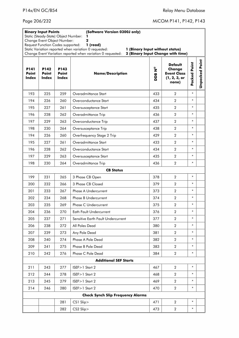
P14x/EN GC/B54 Relay Menu Database
Page 206/232 MiCOM P141, P142, P143
Binary Input Points (Software Version 0300J only)Static (Steady-State) Object Number: 1Change Event Object Number: 2Request Function Codes supported: 1 (read)Static Variation reported when variation 0 requested: 1 (Binary Input without status)Change Event Variation reported when variation 0 requested: 2 (Binary Input Change with time)
P141PointIndex
P142PointIndex
P143PointIndex
Name/Description
DD
B N
O
DefaultChange
Event Class(1, 2, 3, or
none)
Pa
cked
Po
int
Un
pa
cked
Po
int
193 225 259 Overadmittance Start 433 2 *
194 226 260 Overconductance Start 434 2 *
195 227 261 Oversusceptance Start 435 2 *
196 228 262 Overadmittance Trip 436 2 *
197 229 263 Overconductance Trip 437 2 *
198 230 264 Oversusceptance Trip 438 2 *
194 226 260 Overfrequency Stage 2 Trip 429 2 *
195 227 261 Overadmittance Start 433 2 *
196 228 262 Overconductance Start 434 2 *
197 229 263 Oversusceptance Start 435 2 *
198 230 264 Overadmittance Trip 436 2 *
CB Status
199 231 265 3 Phase CB Open 378 2 *
200 232 266 3 Phase CB Closed 379 2 *
201 233 267 Phase A Undercurrent 373 2 *
202 234 268 Phase B Undercurrent 374 2 *
203 235 269 Phase C Undercurrent 375 2 *
204 236 270 Eath Fault Undercurrent 376 2 *
205 237 271 Sensitive Earth Fault Undercurrent 377 2 *
206 238 272 All Poles Dead 380 2 *
207 239 273 Any Pole Dead 381 2 *
208 240 274 Phase A Pole Dead 382 2 *
209 241 275 Phase B Pole Dead 383 2 *
210 242 276 Phase C Pole Dead 384 2 *
Additional SEF Starts
211 243 277 ISEF>1 Start 2 467 2 *
212 244 278 ISEF>1 Start 2 468 2 *
213 245 279 ISEF>1 Start 2 469 2 *
214 246 280 ISEF>1 Start 2 470 2 *
Check Synch Slip Frequency Alarms
281 CS1 Slip> 471 2 *
282 CS2 Slip> 473 2 *

Relay Menu Database P14x/EN GC/B54
MiCOM P141, P142, P143 Page 207/232
Binary Input Points (Software Version 0300J only)Static (Steady-State) Object Number: 1Change Event Object Number: 2Request Function Codes supported: 1 (read)Static Variation reported when variation 0 requested: 1 (Binary Input without status)Change Event Variation reported when variation 0 requested: 2 (Binary Input Change with time)
P141PointIndex
P142PointIndex
P143PointIndex
Name/Description
DD
B N
O
DefaultChange
Event Class(1, 2, 3, or
none)
Pa
cked
Po
int
Un
pa
cked
Po
int
GOOSE Virtual Inputs and Outputs
215 247 283 GOOSE VIP 1 832 2 *
216 248 284 GOOSE VIP 2 833 2 *
217 249 285 GOOSE VIP 3 834 2 *
218 250 286 GOOSE VIP 4 835 2 *
219 251 287 GOOSE VIP 5 836 2 *
220 252 288 GOOSE VIP 6 837 2 *
221 253 289 GOOSE VIP 7 838 2 *
222 254 290 GOOSE VIP 8 839 2 *
223 255 291 GOOSE VIP 9 840 2 *
224 256 292 GOOSE VIP 10 841 2 *
225 257 293 GOOSE VIP 11 842 2 *
226 258 294 GOOSE VIP 12 843 2 *
227 259 295 GOOSE VIP 13 844 2 *
228 260 296 GOOSE VIP 14 845 2 *
229 261 297 GOOSE VIP 15 846 2 *
230 262 298 GOOSE VIP 16 847 2 *
231 263 299 GOOSE VIP 17 848 2 *
232 264 300 GOOSE VIP 18 849 2 *
233 265 301 GOOSE VIP 19 850 2 *
234 266 302 GOOSE VIP 20 851 2 *
235 267 303 GOOSE VIP 21 852 2 *
236 268 304 GOOSE VIP 22 853 2 *
237 269 305 GOOSE VIP 23 854 2 *
238 270 306 GOOSE VIP 24 855 2 *
239 271 307 GOOSE VIP 25 856 2 *
240 272 308 GOOSE VIP 26 857 2 *
241 273 309 GOOSE VIP 27 858 2 *
242 274 310 GOOSE VIP 28 859 2 *
243 275 311 GOOSE VIP 29 860 2 *
244 276 312 GOOSE VIP 30 861 2 *
245 277 313 GOOSE VIP 31 862 2 *
246 278 314 GOOSE VIP 32 863 2 *
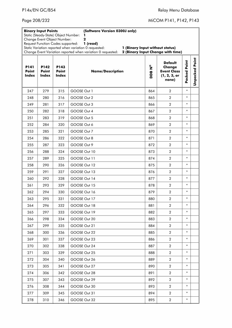
P14x/EN GC/B54 Relay Menu Database
Page 208/232 MiCOM P141, P142, P143
Binary Input Points (Software Version 0300J only)Static (Steady-State) Object Number: 1Change Event Object Number: 2Request Function Codes supported: 1 (read)Static Variation reported when variation 0 requested: 1 (Binary Input without status)Change Event Variation reported when variation 0 requested: 2 (Binary Input Change with time)
P141PointIndex
P142PointIndex
P143PointIndex
Name/Description
DD
B N
O
DefaultChange
Event Class(1, 2, 3, or
none)
Pa
cked
Po
int
Un
pa
cked
Po
int
247 279 315 GOOSE Out 1 864 2 *
248 280 316 GOOSE Out 2 865 2 *
249 281 317 GOOSE Out 3 866 2 *
250 282 318 GOOSE Out 4 867 2 *
251 283 319 GOOSE Out 5 868 2 *
252 284 320 GOOSE Out 6 869 2 *
253 285 321 GOOSE Out 7 870 2 *
254 286 322 GOOSE Out 8 871 2 *
255 287 323 GOOSE Out 9 872 2 *
256 288 324 GOOSE Out 10 873 2 *
257 289 325 GOOSE Out 11 874 2 *
258 290 326 GOOSE Out 12 875 2 *
259 291 327 GOOSE Out 13 876 2 *
260 292 328 GOOSE Out 14 877 2 *
261 293 329 GOOSE Out 15 878 2 *
262 294 330 GOOSE Out 16 879 2 *
263 295 331 GOOSE Out 17 880 2 *
264 296 332 GOOSE Out 18 881 2 *
265 297 333 GOOSE Out 19 882 2 *
266 298 334 GOOSE Out 20 883 2 *
267 299 335 GOOSE Out 21 884 2 *
268 300 336 GOOSE Out 22 885 2 *
269 301 337 GOOSE Out 23 886 2 *
270 302 338 GOOSE Out 24 887 2 *
271 303 339 GOOSE Out 25 888 2 *
272 304 340 GOOSE Out 26 889 2 *
273 305 341 GOOSE Out 27 890 2 *
274 306 342 GOOSE Out 28 891 2 *
275 307 343 GOOSE Out 29 892 2 *
276 308 344 GOOSE Out 30 893 2 *
277 309 345 GOOSE Out 31 894 2 *
278 310 346 GOOSE Out 32 895 2 *
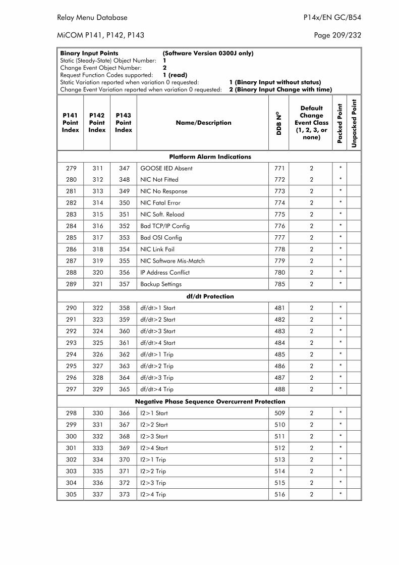
Relay Menu Database P14x/EN GC/B54
MiCOM P141, P142, P143 Page 209/232
Binary Input Points (Software Version 0300J only)Static (Steady-State) Object Number: 1Change Event Object Number: 2Request Function Codes supported: 1 (read)Static Variation reported when variation 0 requested: 1 (Binary Input without status)Change Event Variation reported when variation 0 requested: 2 (Binary Input Change with time)
P141PointIndex
P142PointIndex
P143PointIndex
Name/Description
DD
B N
O
DefaultChange
Event Class(1, 2, 3, or
none)
Pa
cked
Po
int
Un
pa
cked
Po
int
Platform Alarm Indications
279 311 347 GOOSE IED Absent 771 2 *
280 312 348 NIC Not Fitted 772 2 *
281 313 349 NIC No Response 773 2 *
282 314 350 NIC Fatal Error 774 2 *
283 315 351 NIC Soft. Reload 775 2 *
284 316 352 Bad TCP/IP Config 776 2 *
285 317 353 Bad OSI Config 777 2 *
286 318 354 NIC Link Fail 778 2 *
287 319 355 NIC Software Mis-Match 779 2 *
288 320 356 IP Address Conflict 780 2 *
289 321 357 Backup Settings 785 2 *
df/dt Protection
290 322 358 df/dt>1 Start 481 2 *
291 323 359 df/dt>2 Start 482 2 *
292 324 360 df/dt>3 Start 483 2 *
293 325 361 df/dt>4 Start 484 2 *
294 326 362 df/dt>1 Trip 485 2 *
295 327 363 df/dt>2 Trip 486 2 *
296 328 364 df/dt>3 Trip 487 2 *
297 329 365 df/dt>4 Trip 488 2 *
Negative Phase Sequence Overcurrent Protection
298 330 366 I2>1 Start 509 2 *
299 331 367 I2>2 Start 510 2 *
300 332 368 I2>3 Start 511 2 *
301 333 369 I2>4 Start 512 2 *
302 334 370 I2>1 Trip 513 2 *
303 335 371 I2>2 Trip 514 2 *
304 336 372 I2>3 Trip 515 2 *
305 337 373 I2>4 Trip 516 2 *
P14x/EN GC/B54 Relay Menu Database
Page 210/232 MiCOM P141, P142, P143
6.1.1 Time stamping
Time stamping of unpacked binary points is with respect to when a change eventscan is performed by the DNP3 driver, which may yield up to a 0.5s error. The timestamping of packed binary points is with respect to when the point changed state andis not tied to DNP3 driver scan period.
Packed binary points are Digital Data Bus signals as used by the ProgrammableScheme Logic whereas unpacked binary points are generally not part of the DigitalData Bus.
6.2 Binary output status points and control relay output block
The following table lists both the Binary Output Status Points (Object 10) and theControl Relay Output Block (Object 12).
Binary Output Status points are included in Class 0 data set. (Since there is not achange-event object for the binary outputs, the binary output points are not part ofthe class 1, 2, or 3 data sets). It is not possible to configure the class 0 membershipof this object with MiCOM S1.
The validity of each point is reported through the “online” bit in the “flag”, which issupplied for each point with the “with flag” object variations. Points reported asbeing offline, will typically be points that are invalid for the relay’s currentconfiguration, which is a product of its model number and current settings.
The Control Relay Output Block (CROB) implementation is compliant with the DNPtechnical bulletin TB2000-006, which rescinds CROB behaviours specified in theoriginal four document set and addendum sub-set documents.
The following text is a brief summary of DNP technical bulletin TB2000-006:
Each control point in the CROB may be either a "complimentary control function" or a"single function".
Examples of complimentary control functions are:
• Trip and close
• On and Off
Examples of single-function controls are:
• Trip
• Activate
A point index cannot support both complimentary and single-function methods ofoperation.
Complimentary control function points require the use of a complementary control-code pair. The CROB provides two sets of control pairs:
• Code 0316 "Latch On" and code 0416 "Latch Off"
• Code 4116 "Pulse On/Close" and code 8116 "Pulse On/Trip"
In DNP there is no significance to these codes; they do the same thing. Acomplimentary-control point may "permit" either or both of these pairs. If a pointpermits both pairs of codes then:
• Latch On and Pulse Close must perform the same function
Relay Menu Database P14x/EN GC/B54
MiCOM P141, P142, P143 Page 211/232
• Latch Off and Pulse Trip must perform the same function
Single-function control points may permit one or more of the following control codes:
• Code 0116 "Pulse On"
• Code 0316 "Latch On"
• Code 0416 "Latch Off"
• Code 4116 "Pulse On/Close
• Code 8116 "Pulse On/Trip"
There is no significance to these codes; they do the same thing. Each of thepermitted single-function codes must perform the same function on a given single-function point index.
The original DNP 3.0 specification for the CROB "exposes the details of the devicehardware to the protocol stack. This is unnecessary and creates interoperabilityissues". Moreover, "some IED vendors have implemented points that do differentthings based on the control code that is sent. " E.g. a point latches for the latch codesand pulses for the pulse codes. "This perverts the original intent of the CROB andmakes it impossible for masters that statically configure control codes to beinteroperable with such [IEDs]. This type of implementation is also not transportableacross legacy protocol boundaries."
In the following table, point indices that are marked as “unpaired” will accept thecorrespondingly marked control codes and treat them identically as a “trigger” for thecommand action associated with the point. Unpaired points do not have a statevalue that can be read and a read request, whilst completing successfully, will alwaysreturn a value of zero.
Points that are marked as “paired” behave as complimentary-controls and have astate value that can be read. The Latch On and Pulse On/Close control-codes set thespecified output status point whilst the Latch Off and Pulse On/Trip codes reset it.
The Count field is not supported and must be either zero or one. The On-time, andOff-time fields are ignored. The Queue and Clear bits in the Control-Code field arenot supported and must be zero. The “Pulse Off” control-code code is not supported.
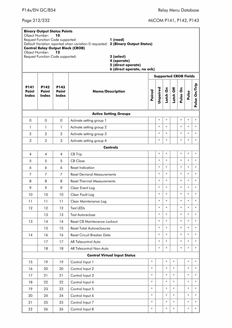
P14x/EN GC/B54 Relay Menu Database
Page 212/232 MiCOM P141, P142, P143
Binary Output Status PointsObject Number: 10Request Function Code supported: 1 (read)Default Variation reported when variation 0 requested: 2 (Binary Output Status)Control Relay Output Block (CROB)Object Number: 12Request Function Code supported: 3 (select)
4 (operate)5 (direct operate)6 (direct operate, no ack)
Supported CROB Fields
P141PointIndex
P142PointIndex
P143PointIndex
Name/Description
Pa
ired
Un
pa
ired
Latc
h O
n
Latc
h O
ff
Pu
lse O
n
Pu
lse
Pu
lse O
n/T
rip
Active Setting Groups
0 0 0 Activate setting group 1 * * * * *
1 1 1 Activate setting group 2 * * * * *
2 2 2 Activate setting group 3 * * * * *
3 3 3 Activate setting group 4 * * * * *
Controls
4 4 4 CB Trip * * * * *
5 5 5 CB Close * * * * *
6 6 6 Reset Indication * * * * *
7 7 7 Reset Demand Measurements * * * * *
8 8 8 Reset Thermal Measurements * * * * *
9 9 9 Clear Event Log * * * * *
10 10 10 Clear Fault Log * * * * *
11 11 11 Clear Maintenance Log * * * * *
12 12 12 Test LEDs * * * * *
13 13 Test Autoreclose * * * * *
13 14 14 Reset CB Maintenance Lockout * * * * *
15 15 Reset Total Autoreclosures * * * * *
14 16 16 Reset Circuit Breaker Data * * * * *
17 17 AR Telecontrol Auto * * * * *
18 18 AR Telecontrol Non-Auto * * * * *
Control Virtual Input Status
15 19 19 Control Input 1 * * * * *
16 20 20 Control Input 2 * * * * *
17 21 21 Control Input 3 * * * * *
18 22 22 Control Input 4 * * * * *
19 23 23 Control Input 5 * * * * *
20 24 24 Control Input 6 * * * * *
21 25 25 Control Input 7 * * * * *
22 26 26 Control Input 8 * * * * *
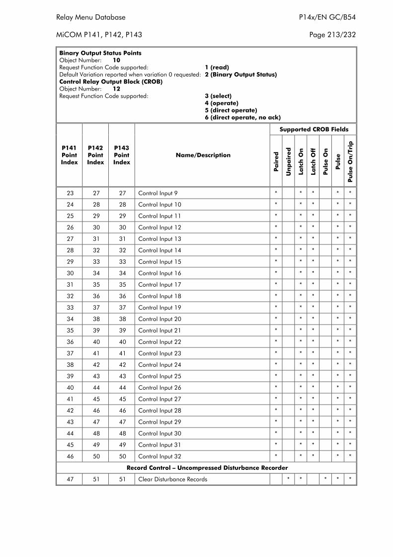
Relay Menu Database P14x/EN GC/B54
MiCOM P141, P142, P143 Page 213/232
Binary Output Status PointsObject Number: 10Request Function Code supported: 1 (read)Default Variation reported when variation 0 requested: 2 (Binary Output Status)Control Relay Output Block (CROB)Object Number: 12Request Function Code supported: 3 (select)
4 (operate)5 (direct operate)6 (direct operate, no ack)
Supported CROB Fields
P141PointIndex
P142PointIndex
P143PointIndex
Name/Description
Pa
ired
Un
pa
ired
Latc
h O
n
Latc
h O
ff
Pu
lse O
n
Pu
lse
Pu
lse O
n/T
rip
23 27 27 Control Input 9 * * * * *
24 28 28 Control Input 10 * * * * *
25 29 29 Control Input 11 * * * * *
26 30 30 Control Input 12 * * * * *
27 31 31 Control Input 13 * * * * *
28 32 32 Control Input 14 * * * * *
29 33 33 Control Input 15 * * * * *
30 34 34 Control Input 16 * * * * *
31 35 35 Control Input 17 * * * * *
32 36 36 Control Input 18 * * * * *
33 37 37 Control Input 19 * * * * *
34 38 38 Control Input 20 * * * * *
35 39 39 Control Input 21 * * * * *
36 40 40 Control Input 22 * * * * *
37 41 41 Control Input 23 * * * * *
38 42 42 Control Input 24 * * * * *
39 43 43 Control Input 25 * * * * *
40 44 44 Control Input 26 * * * * *
41 45 45 Control Input 27 * * * * *
42 46 46 Control Input 28 * * * * *
43 47 47 Control Input 29 * * * * *
44 48 48 Control Input 30 * * * * *
45 49 49 Control Input 31 * * * * *
46 50 50 Control Input 32 * * * * *
Record Control – Uncompressed Disturbance Recorder
47 51 51 Clear Disturbance Records * * * * *
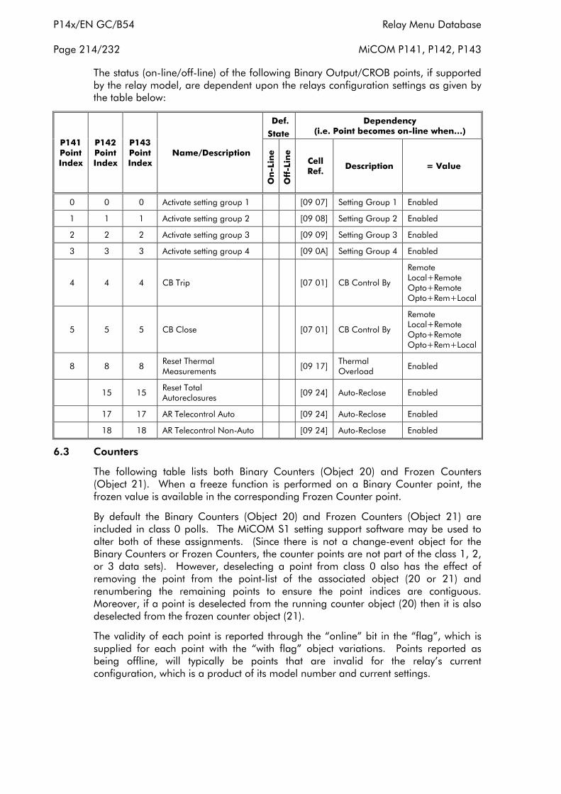
P14x/EN GC/B54 Relay Menu Database
Page 214/232 MiCOM P141, P142, P143
The status (on-line/off-line) of the following Binary Output/CROB points, if supportedby the relay model, are dependent upon the relays configuration settings as given bythe table below:
Def.
State
Dependency(i.e. Point becomes on-line when…)
P141PointIndex
P142PointIndex
P143PointIndex
Name/Description
On
-Lin
e
Off
-Lin
e
CellRef.
Description = Value
0 0 0 Activate setting group 1 [09 07] Setting Group 1 Enabled
1 1 1 Activate setting group 2 [09 08] Setting Group 2 Enabled
2 2 2 Activate setting group 3 [09 09] Setting Group 3 Enabled
3 3 3 Activate setting group 4 [09 0A] Setting Group 4 Enabled
4 4 4 CB Trip [07 01] CB Control By
RemoteLocal+RemoteOpto+RemoteOpto+Rem+Local
5 5 5 CB Close [07 01] CB Control By
RemoteLocal+RemoteOpto+RemoteOpto+Rem+Local
8 8 8Reset ThermalMeasurements
[09 17]ThermalOverload
Enabled
15 15Reset TotalAutoreclosures
[09 24] Auto-Reclose Enabled
17 17 AR Telecontrol Auto [09 24] Auto-Reclose Enabled
18 18 AR Telecontrol Non-Auto [09 24] Auto-Reclose Enabled
6.3 Counters
The following table lists both Binary Counters (Object 20) and Frozen Counters(Object 21). When a freeze function is performed on a Binary Counter point, thefrozen value is available in the corresponding Frozen Counter point.
By default the Binary Counters (Object 20) and Frozen Counters (Object 21) areincluded in class 0 polls. The MiCOM S1 setting support software may be used toalter both of these assignments. (Since there is not a change-event object for theBinary Counters or Frozen Counters, the counter points are not part of the class 1, 2,or 3 data sets). However, deselecting a point from class 0 also has the effect ofremoving the point from the point-list of the associated object (20 or 21) andrenumbering the remaining points to ensure the point indices are contiguous.Moreover, if a point is deselected from the running counter object (20) then it is alsodeselected from the frozen counter object (21).
The validity of each point is reported through the “online” bit in the “flag”, which issupplied for each point with the “with flag” object variations. Points reported asbeing offline, will typically be points that are invalid for the relay’s currentconfiguration, which is a product of its model number and current settings.
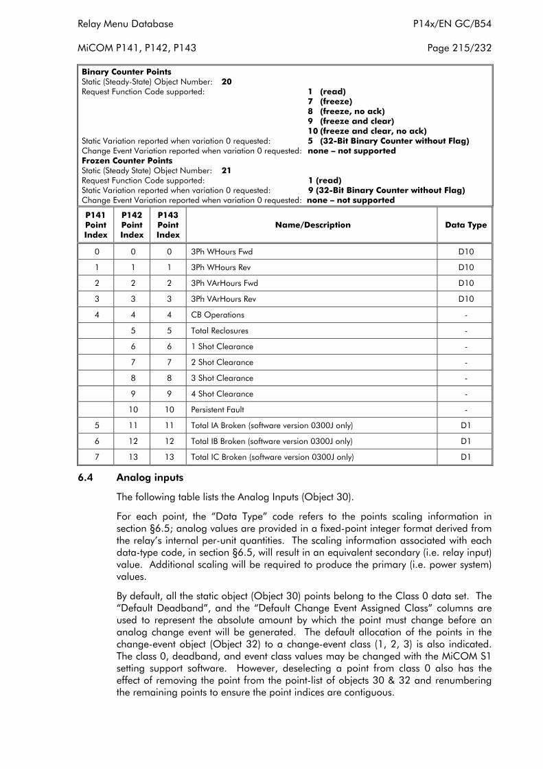
Relay Menu Database P14x/EN GC/B54
MiCOM P141, P142, P143 Page 215/232
Binary Counter PointsStatic (Steady-State) Object Number: 20Request Function Code supported: 1 (read)
7 (freeze)8 (freeze, no ack)9 (freeze and clear)10 (freeze and clear, no ack)
Static Variation reported when variation 0 requested: 5 (32-Bit Binary Counter without Flag)Change Event Variation reported when variation 0 requested: none – not supportedFrozen Counter PointsStatic (Steady State) Object Number: 21Request Function Code supported: 1 (read)Static Variation reported when variation 0 requested: 9 (32-Bit Binary Counter without Flag)Change Event Variation reported when variation 0 requested: none – not supported
P141PointIndex
P142PointIndex
P143PointIndex
Name/Description Data Type
0 0 0 3Ph WHours Fwd D10
1 1 1 3Ph WHours Rev D10
2 2 2 3Ph VArHours Fwd D10
3 3 3 3Ph VArHours Rev D10
4 4 4 CB Operations -
5 5 Total Reclosures -
6 6 1 Shot Clearance -
7 7 2 Shot Clearance -
8 8 3 Shot Clearance -
9 9 4 Shot Clearance -
10 10 Persistent Fault -
5 11 11 Total IA Broken (software version 0300J only) D1
6 12 12 Total IB Broken (software version 0300J only) D1
7 13 13 Total IC Broken (software version 0300J only) D1
6.4 Analog inputs
The following table lists the Analog Inputs (Object 30).
For each point, the “Data Type” code refers to the points scaling information insection §6.5; analog values are provided in a fixed-point integer format derived fromthe relay’s internal per-unit quantities. The scaling information associated with eachdata-type code, in section §6.5, will result in an equivalent secondary (i.e. relay input)value. Additional scaling will be required to produce the primary (i.e. power system)values.
By default, all the static object (Object 30) points belong to the Class 0 data set. The“Default Deadband”, and the “Default Change Event Assigned Class” columns areused to represent the absolute amount by which the point must change before ananalog change event will be generated. The default allocation of the points in thechange-event object (Object 32) to a change-event class (1, 2, 3) is also indicated.The class 0, deadband, and event class values may be changed with the MiCOM S1setting support software. However, deselecting a point from class 0 also has theeffect of removing the point from the point-list of objects 30 & 32 and renumberingthe remaining points to ensure the point indices are contiguous.
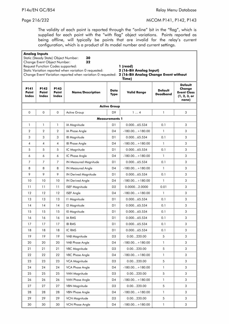
P14x/EN GC/B54 Relay Menu Database
Page 216/232 MiCOM P141, P142, P143
The validity of each point is reported through the “online” bit in the “flag”, which issupplied for each point with the “with flag” object variations. Points reported asbeing offline, will typically be points that are invalid for the relay’s currentconfiguration, which is a product of its model number and current settings.
Analog InputsStatic (Steady State) Object Number: 30Change Event Object Number: 32Request Function Codes supported: 1 (read)Static Variation reported when variation 0 requested: 2 (16-Bit Analog Input)Change Event Variation reported when variation 0 requested: 2 (16-Bit Analog Change Event without
Time)
P141PointIndex
P142PointIndex
P143PointIndex
Name/Description DataType Valid Range Default
Deadband
DefaultChange
Event Class(1, 2, 3, or
none)
Active Group
0 0 0 Active Group D9 1 … 4 1 3
Measurements 1
1 1 1 IA Magnitude D1 0.000…65.534 0.1 3
2 2 2 IA Phase Angle D4 -180.00…+180.00 1 3
3 3 3 IB Magnitude D1 0.000…65.534 0.1 3
4 4 4 IB Phase Angle D4 -180.00…+180.00 1 3
5 5 5 IC Magnitude D1 0.000…65.534 0.1 3
6 6 6 IC Phase Angle D4 -180.00…+180.00 1 3
7 7 7 IN Measured Magnitude D1 0.000…65.534 0.1 3
8 8 8 IN Measured Angle D4 -180.00…+180.00 1 3
9 9 9 IN Derived Magnitude D1 0.000…65.534 0.1 3
10 10 10 IN Derived Angle D4 -180.00…+180.00 1 3
11 11 11 ISEF Magnitude D2 0.0000…2.0000 0.01 3
12 12 12 ISEF Angle D4 -180.00…+180.00 1 3
13 13 13 I1 Magnitude D1 0.000…65.534 0.1 3
14 14 14 I2 Magnitude D1 0.000…65.534 0.1 3
15 15 15 I0 Magnitude D1 0.000…65.534 0.1 3
16 16 16 IA RMS D1 0.000…65.534 0.1 3
17 17 17 IB RMS D1 0.000…65.534 0.1 3
18 18 18 IC RMS D1 0.000…65.534 0.1 3
19 19 19 VAB Magnitude D3 0.00…220.00 5 3
20 20 20 VAB Phase Angle D4 -180.00…+180.00 1 3
21 21 21 VBC Magnitude D3 0.00…220.00 5 3
22 22 22 VBC Phase Angle D4 -180.00…+180.00 1 3
23 23 23 VCA Magnitude D3 0.00…220.00 5 3
24 24 24 VCA Phase Angle D4 -180.00…+180.00 1 3
25 25 25 VAN Magnitude D3 0.00…220.00 5 3
26 26 26 VAN Phase Angle D4 -180.00…+180.00 1 3
27 27 27 VBN Magnitude D3 0.00…220.00 5 3
28 28 28 VBN Phase Angle D4 -180.00…+180.00 1 3
29 29 29 VCN Magnitude D3 0.00…220.00 5 3
30 30 30 VCN Phase Angle D4 -180.00…+180.00 1 3
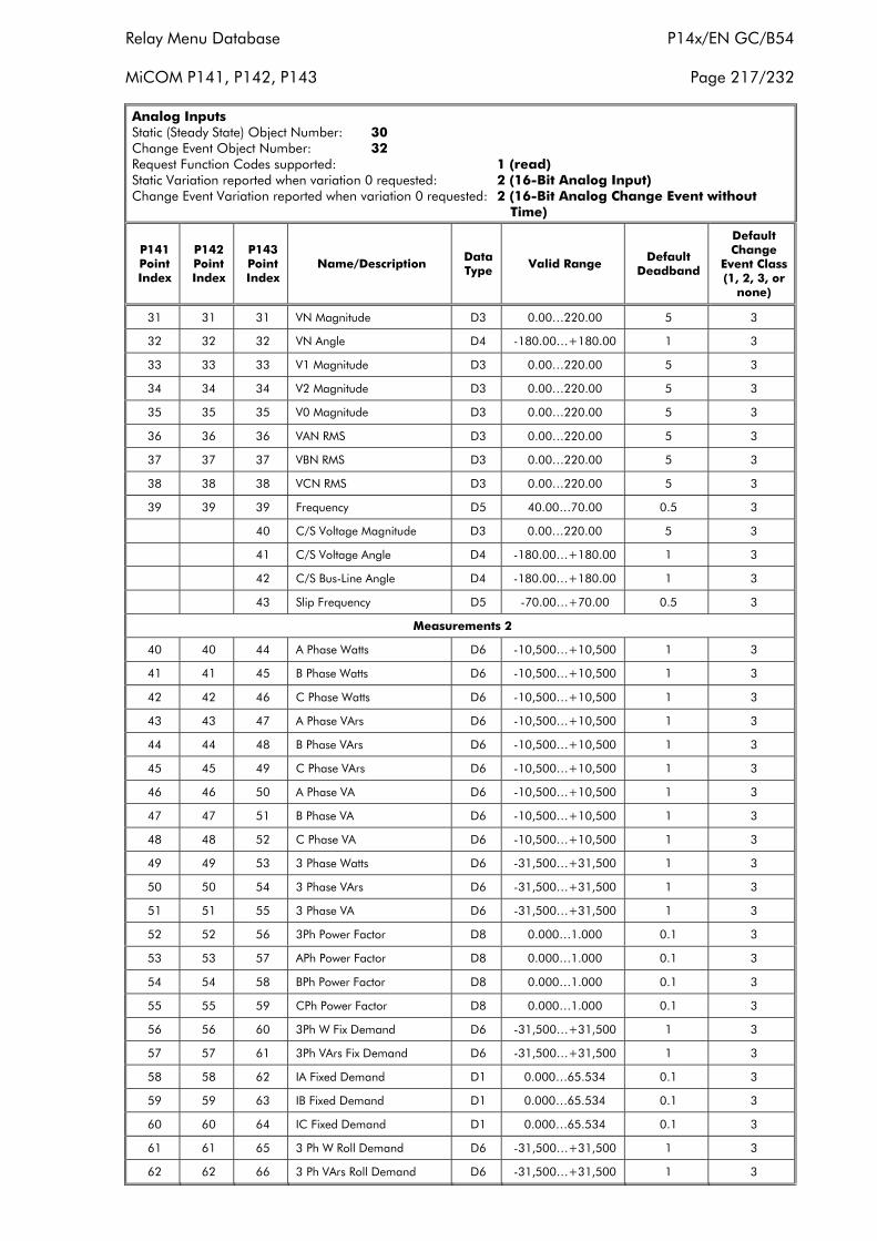
Relay Menu Database P14x/EN GC/B54
MiCOM P141, P142, P143 Page 217/232
Analog InputsStatic (Steady State) Object Number: 30Change Event Object Number: 32Request Function Codes supported: 1 (read)Static Variation reported when variation 0 requested: 2 (16-Bit Analog Input)Change Event Variation reported when variation 0 requested: 2 (16-Bit Analog Change Event without
Time)
P141PointIndex
P142PointIndex
P143PointIndex
Name/Description DataType Valid Range Default
Deadband
DefaultChange
Event Class(1, 2, 3, or
none)
31 31 31 VN Magnitude D3 0.00…220.00 5 3
32 32 32 VN Angle D4 -180.00…+180.00 1 3
33 33 33 V1 Magnitude D3 0.00…220.00 5 3
34 34 34 V2 Magnitude D3 0.00…220.00 5 3
35 35 35 V0 Magnitude D3 0.00…220.00 5 3
36 36 36 VAN RMS D3 0.00…220.00 5 3
37 37 37 VBN RMS D3 0.00…220.00 5 3
38 38 38 VCN RMS D3 0.00…220.00 5 3
39 39 39 Frequency D5 40.00…70.00 0.5 3
40 C/S Voltage Magnitude D3 0.00…220.00 5 3
41 C/S Voltage Angle D4 -180.00…+180.00 1 3
42 C/S Bus-Line Angle D4 -180.00…+180.00 1 3
43 Slip Frequency D5 -70.00…+70.00 0.5 3
Measurements 2
40 40 44 A Phase Watts D6 -10,500…+10,500 1 3
41 41 45 B Phase Watts D6 -10,500…+10,500 1 3
42 42 46 C Phase Watts D6 -10,500…+10,500 1 3
43 43 47 A Phase VArs D6 -10,500…+10,500 1 3
44 44 48 B Phase VArs D6 -10,500…+10,500 1 3
45 45 49 C Phase VArs D6 -10,500…+10,500 1 3
46 46 50 A Phase VA D6 -10,500…+10,500 1 3
47 47 51 B Phase VA D6 -10,500…+10,500 1 3
48 48 52 C Phase VA D6 -10,500…+10,500 1 3
49 49 53 3 Phase Watts D6 -31,500…+31,500 1 3
50 50 54 3 Phase VArs D6 -31,500…+31,500 1 3
51 51 55 3 Phase VA D6 -31,500…+31,500 1 3
52 52 56 3Ph Power Factor D8 0.000…1.000 0.1 3
53 53 57 APh Power Factor D8 0.000…1.000 0.1 3
54 54 58 BPh Power Factor D8 0.000…1.000 0.1 3
55 55 59 CPh Power Factor D8 0.000…1.000 0.1 3
56 56 60 3Ph W Fix Demand D6 -31,500…+31,500 1 3
57 57 61 3Ph VArs Fix Demand D6 -31,500…+31,500 1 3
58 58 62 IA Fixed Demand D1 0.000…65.534 0.1 3
59 59 63 IB Fixed Demand D1 0.000…65.534 0.1 3
60 60 64 IC Fixed Demand D1 0.000…65.534 0.1 3
61 61 65 3 Ph W Roll Demand D6 -31,500…+31,500 1 3
62 62 66 3 Ph VArs Roll Demand D6 -31,500…+31,500 1 3
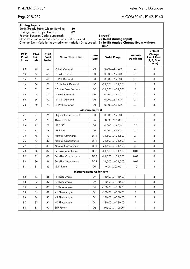
P14x/EN GC/B54 Relay Menu Database
Page 218/232 MiCOM P141, P142, P143
Analog InputsStatic (Steady State) Object Number: 30Change Event Object Number: 32Request Function Codes supported: 1 (read)Static Variation reported when variation 0 requested: 2 (16-Bit Analog Input)Change Event Variation reported when variation 0 requested: 2 (16-Bit Analog Change Event without
Time)
P141PointIndex
P142PointIndex
P143PointIndex
Name/Description DataType Valid Range Default
Deadband
DefaultChange
Event Class(1, 2, 3, or
none)
63 63 67 IA Roll Demand D1 0.000…65.534 0.1 3
64 64 68 IB Roll Demand D1 0.000…65.534 0.1 3
65 65 69 IC Roll Demand D1 0.000…65.534 0.1 3
66 66 70 3Ph W Peak Demand D6 -31,500…+31,500 1 3
67 67 71 3Ph VAr Peak Demand D6 -31,500…+31,500 1 3
68 68 72 IA Peak Demand D1 0.000…65.534 0.1 3
69 69 73 IB Peak Demand D1 0.000…65.534 0.1 3
70 70 74 IC Peak Demand D1 0.000…65.534 0.1 3
Measurements 3
71 71 75 Highest Phase Current D1 0.000…65.534 0.1 3
72 72 76 Thermal State D7 0.00…200.00 10 3
73 73 77 IREF Diff D1 0.000…65.534 0.1 3
74 74 78 IREF Bias D1 0.000…65.534 0.1 3
75 75 79 Neutral Admittance D11 -31,500…+31,500 0.1 3
76 76 80 Neutral Conductance D11 -31,500…+31,500 0.1 3
77 77 81 Neutral Susceptance D11 -31,500…+31,500 0.1 3
78 78 82 Sensitive Admittance D12 -31,500…+31,500 0.01 3
79 79 83 Sensitive Conductance D12 -31,500…+31,500 0.01 3
80 80 84 Sensitive Susceptance D12 -31,500…+31,500 0.01 3
81 81 85 I2/I1 Ratio D7 0.00…200.00 10 3
Measurements Addendum
82 82 86 I1 Phase Angle D4 -180.00…+180.00 1 3
83 83 87 I2 Phase Angle D4 -180.00…+180.00 1 3
84 84 88 I0 Phase Angle D4 -180.00…+180.00 1 3
85 85 89 V1 Phase Angle D4 -180.00…+180.00 1 3
86 86 90 V2 Phase Angle D4 -180.00…+180.00 1 3
87 87 91 V0 Phase Angle D4 -180.00…+180.00 1 3
88 88 92 SEF Power D6 -10500…+10500 1 3
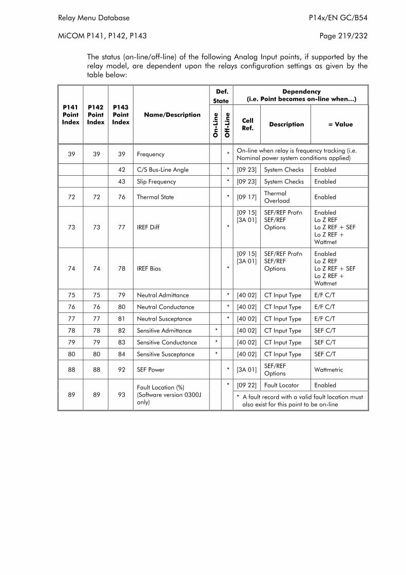
Relay Menu Database P14x/EN GC/B54
MiCOM P141, P142, P143 Page 219/232
The status (on-line/off-line) of the following Analog Input points, if supported by therelay model, are dependent upon the relays configuration settings as given by thetable below:
Def.
State
Dependency(i.e. Point becomes on-line when…)
P141PointIndex
P142PointIndex
P143PointIndex
Name/Description
On
-Lin
e
Off
-Lin
e
CellRef.
Description = Value
39 39 39 Frequency * On-line when relay is frequency tracking (i.e.Nominal power system conditions applied)
42 C/S Bus-Line Angle * [09 23] System Checks Enabled
43 Slip Frequency * [09 23] System Checks Enabled
72 72 76 Thermal State * [09 17]ThermalOverload
Enabled
73 73 77 IREF Diff *
[09 15][3A 01]
SEF/REF Prot'nSEF/REFOptions
EnabledLo Z REFLo Z REF + SEFLo Z REF +Wattmet
74 74 78 IREF Bias *
[09 15][3A 01]
SEF/REF Prot'nSEF/REFOptions
EnabledLo Z REFLo Z REF + SEFLo Z REF +Wattmet
75 75 79 Neutral Admittance * [40 02] CT Input Type E/F C/T
76 76 80 Neutral Conductance * [40 02] CT Input Type E/F C/T
77 77 81 Neutral Susceptance * [40 02] CT Input Type E/F C/T
78 78 82 Sensitive Admittance * [40 02] CT Input Type SEF C/T
79 79 83 Sensitive Conductance * [40 02] CT Input Type SEF C/T
80 80 84 Sensitive Susceptance * [40 02] CT Input Type SEF C/T
88 88 92 SEF Power * [3A 01]SEF/REFOptions
Wattmetric
[09 22] Fault Locator Enabled
89 89 93Fault Location (%)(Software version 0300Jonly)
*
* A fault record with a valid fault location must also exist for this point to be on-line
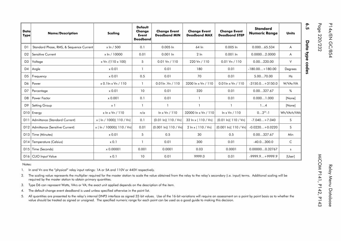
P14x/EN G
C/B54
Relay Menu D
atabase
Page 220/232M
iCO
M P141, P142, P143
6.5
Data
type co
des
Units
A
A
V
Degrees
Hz
W/VAr/VA
%
[None]
[None]
Wh/VArh/VAh
S
S
Min
C
s
[User]
StandardNumeric Range
0.000…65.534
0.0000…2.0000
0.00…220.00
-180.00…+180.00
5.00…70.00
-3150.0…+3150.0
0.00…327.67
0.000…1.000
1…4
0…231-1
-7.040…+7.040
-0.0220…+0.0220
0.00…327.67
-40.0…300.0
0.00000…0.32767
-9999.9…+9999.9
Change EventDeadband STEP
0.005 In
0.001 In
0.01 Vn / 110
0.01
0.01
0.01In x Vn / 110
0.01
0.01
1
In x Vn / 110
(0.01 In)( 110 / Vn)
(0.001 In)( 110 / Vn)
0.5
0.01
0.0001
0.01
Change EventDeadband MAX
64 In
2 In
220 Vn / 110
180
70
3200 In x Vn / 110
320
1
1
32000 In x Vn / 110
32 In x ( 110 / Vn)
2 In x ( 110 / Vn)
30
300
0.03
9999.0
Change EventDeadband MIN
0.005 In
0.001 In
0.01 Vn / 110
0.01
0.01
0.01In .Vn / 110
0.01
0.01
1
In x Vn / 110
(0.01 In)( 110 / Vn)
(0.001 In)( 110 / Vn)
0.5
0.01
0.0001
0.01
DefaultChangeEvent
Deadband
0.1
0.01
5
1
0.5
1
10
0.1
1
n/a
0.1
0.01
5
1
0.001
10
Scaling
x In / 500
x In / 10000
x Vn /(110 x 100)
x 0.01
x 0.01
x 0.1In x Vn / 110
x 0.01
x 0.001
x 1
x In x Vn / 110
x ( In / 1000)( 110 / Vn)
x ( In / 10000)( 110 / Vn)
x 0.01
x 0.1
x 0.00001
x 0.1
Name/Description
Standard Phase, RMS, & Sequence Current
Sensitive Current
Voltage
Angle
Frequency
Power
Percentage
Power Factor
Setting Group
Energy
Admittance (Standard Current)
Admittance (Sensitive Current)
Time (Minutes)
Temperature (Celsius)
Time (Seconds)
CLIO Input Value
DataType
D1
D2
D3
D4
D5
D6
D7
D8
D9
D10
D11
D12
D13
D14
D15
D16
Notes:
1. In and Vn are the “physical” relay input ratings: 1A or 5A and 110V or 440V respectively.
2. The scaling value represents the multiplier required for the master station to scale the value obtained from the relay to the relay’s secondary (i.e. input) terms. Additional scaling will berequired by the master station to obtain primary quantities.
3. Type D6 can represent Watts, VArs or VA; the exact unit applied depends on the description of the item.
4. The default change event deadband is used unless specified otherwise in the point list.
5. All quantities are presented to the relay’s internal DNP3 interface as signed 32-bit values. Use of the 16-bit variations will require an assessment on a point by point basis as to whether thevalue should be treated as signed or unsigned. The specified numeric range for each point can be used as a good guide to making this decision.
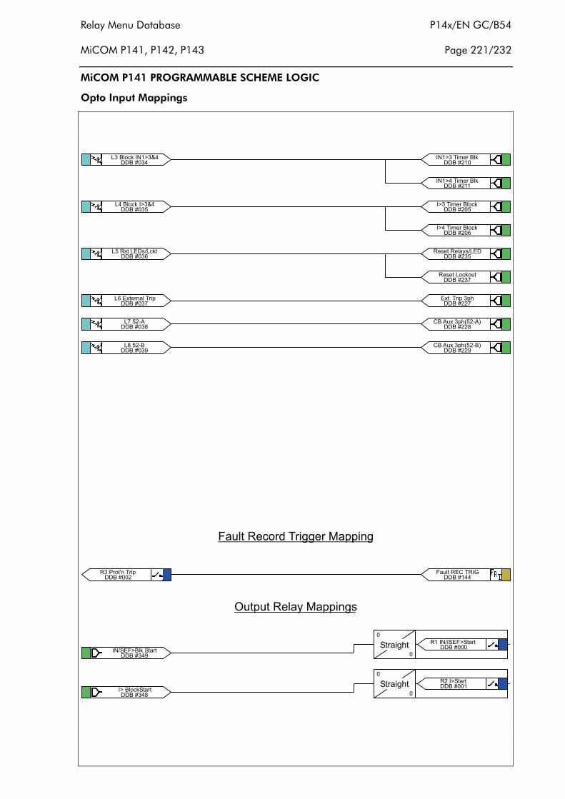
Relay Menu Database P14x/EN GC/B54
MiCOM P141, P142, P143 Page 221/232
MiCOM P141 PROGRAMMABLE SCHEME LOGIC
Opto Input Mappings
��������������� ��
������������������������ �
��������������� ������
��������������� ����
������������������������
��������������������� !
�������"����#$%
�������&�"��#$�
'��� ()��
�
��� �� '�*�'������������
'��� ()��
�
�#� �'������������
�����##"+��%,���!)-�#$%.
�����##����/��� !��!)
��������*�,����+��� 0
�����##&+��%,���!)-�#$�.
�������& ��'�*����'����
�������" �����'����
�������#���1��2���� !
�����#�� ������ 3�����
�����#�� ������ 3�����
�����#�� ���� 3������
�����#�� ���� 3������
�����#�����������4�����
�����#�����������,�
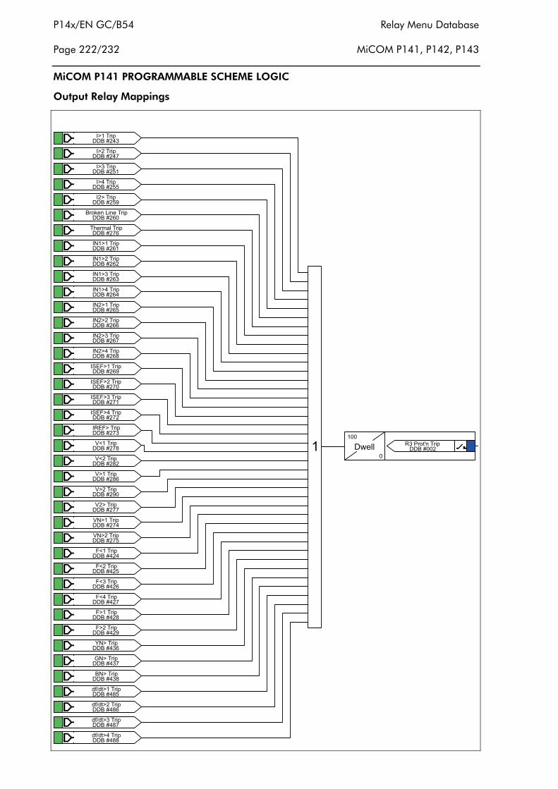
P14x/EN GC/B54 Relay Menu Database
Page 222/232 MiCOM P141, P142, P143
MiCOM P141 PROGRAMMABLE SCHEME LOGIC
Output Relay Mappings
�����#�� ����� !
�����#�� �#��� !
�����#�� ����� !
�����#�� ����� !
�����#�& #���� !
�����#��������� ����� !
�����#���)��3���� !
�����#�� ������� !
�����#�# ���#��� !
�����#�� ������� !
�����#�� ������� !
�����#�� �#����� !
�����#�� �#�#��� !
�����#�� �#����� !
�����#�" �#����� !
�����#�& '�*����� !
�����#�� '�*�#��� !
�����#�� '�*����� !
�����#�# '�*����� !
�����#�� ��*���� !
�����#�"56���� !
�����#"#56#��� !
�����#"�5����� !
�����#��5#���� !
�����#��5������ !
�����#��5��#��� !
������#�*6���� !
������#�*6#��� !
������#�*6���� !
������#�*6���� !
������#"*����� !
������#&*�#��� !
��������7����� !
��������0����� !
�������"������ !
� �8����
�
���1��2���� !�������#
�����#&�5�#��� !
������"�9:�9������ !
������"�9:�9��#��� !
������"�9:�9������ !
������""9:�9������ !
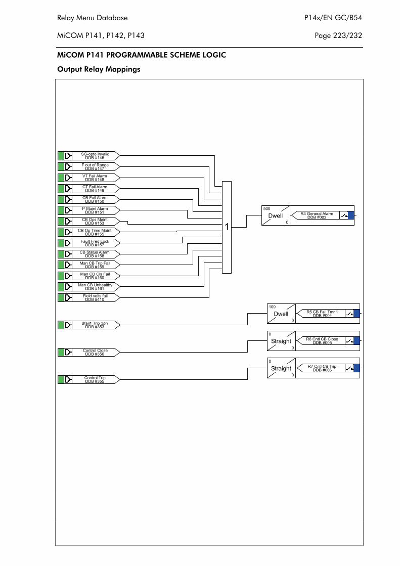
Relay Menu Database P14x/EN GC/B54
MiCOM P141, P142, P143 Page 223/232
MiCOM P141 PROGRAMMABLE SCHEME LOGIC
Output Relay Mappings
��������'0$!�� �;� 9
��������*�,��:����(�
�������"5��*� �%��3
�������&+��*� �%��3
��������+��*� �%��3
�������� <�=� ���%��3
��������+��>!��=� ��
��������+��>!�� 3��=� ��
��������*�,��*��?����
�������"+��'���,��%��3
�������&=���+���� !�*�
��������=���+��+��*�
��������=���+��@�)���)4
��������* �9�;���:�
��8�
���
�
���0������%��3��������
���������:� ���� !��!)
��������+����+��
��������+������ !
�8����
�
���+��*� ��3�����������
'��� ()��
�
���+���+��+����������
'��� ()��
�
���+���+���� !��������
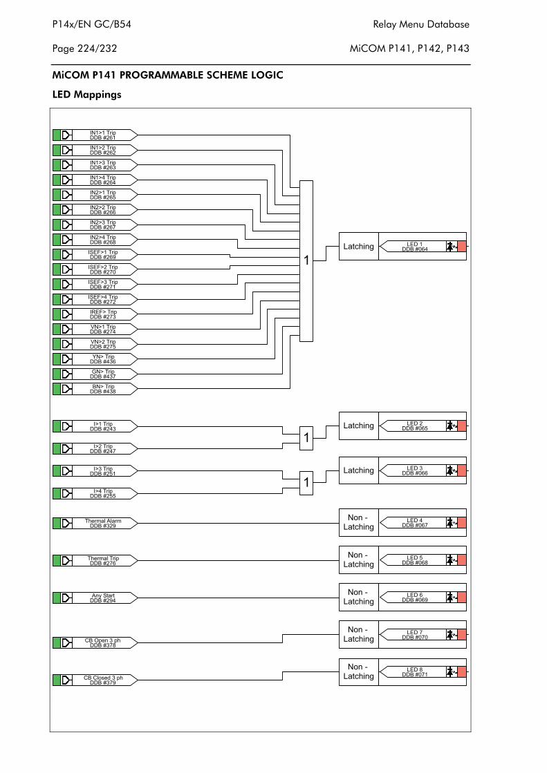
P14x/EN GC/B54 Relay Menu Database
Page 224/232 MiCOM P141, P142, P143
MiCOM P141 PROGRAMMABLE SCHEME LOGIC
LED Mappings
�����#�� ������� !
�����#�# ���#��� !
�����#�� ������� !
�����#�� ������� !
�����#�� �#����� !
�����#�� �#�#��� !
�����#�� �#����� !
�����#�" �#����� !
�����#�& '�*����� !
�����#�� '�*�#��� !
�����#�� '�*����� !
�����#�# '�*����� !
�����#�� ��*���� !
�����#��5������ !
�����#��5��#��� !
��������7����� !
��������0����� !
�������"������ !
�������������) �( �����
�����#�� ����� !
�����#�� �#��� !
�����#�� ����� !
�����#�� ����� !
�������"+��>!�����!)
�������&+��+��9���!)
�
�
������������) �( ����#
������������) �( �����
�����������$
����) �(�����
�������"���$
����) �(�����
�������&���$
����) �(�����
�����������$
����) �(�����
�����������$
����) �(����"
�����#���)��3���� !
������#&�)��3��%��3
�����#&�%�4�'����
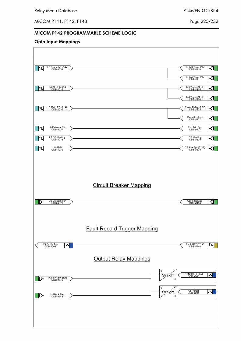
Relay Menu Database P14x/EN GC/B54
MiCOM P141, P142, P143 Page 225/232
MiCOM P142 PROGRAMMABLE SCHEME LOGIC
Opto Input Mappings
��������������� ������
��������������� ����
������������������������
��������������������� !
�������"���+��A���)4
�������&�"��#$�
'��� ()��
�
��� �� '�*�'������������
'��� ()��
�
�#� �'������������
�����##����/��� !��!)
��������*�,����+��� 0
�����##&+��%,���!)-�#$�.
�������& ��'�*����'����
�������" �����'����
�������#���1��2���� !
�����#�� ������ 3�����
�����#�� ������ 3�����
�����#�� ���� 3������
�����#�� ���� 3������
�����#�����������,�
�����#�����������4�����
�������&+��+��9���!)
��������+�� ��'��; ��
�����#��+��A���)4
+ ��, ����������=�!! �(
*�,������9��� ((���=�!! �(
>,�!,�����4�=�!! �(�
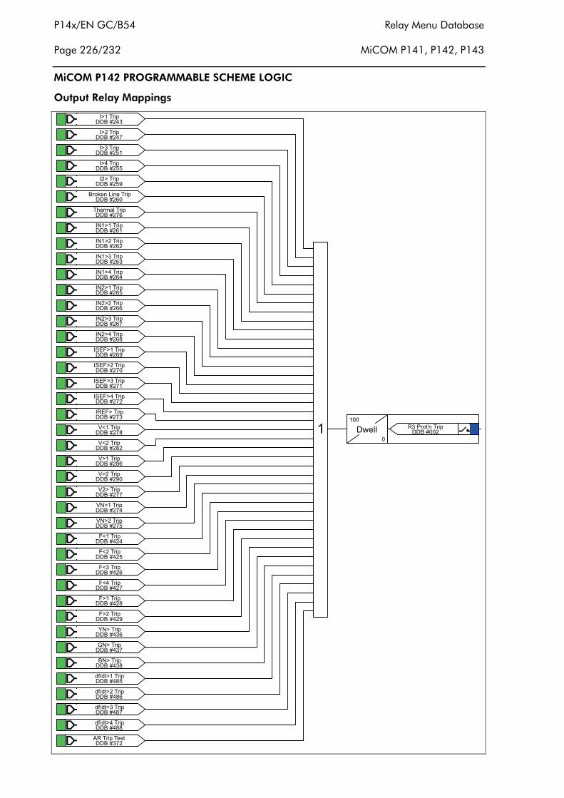
P14x/EN GC/B54 Relay Menu Database
Page 226/232 MiCOM P141, P142, P143
MiCOM P142 PROGRAMMABLE SCHEME LOGIC
Output Relay Mappings
�����#�� ����� !
�����#�� �#��� !
�����#�� ����� !
�����#�� ����� !
�����#�& #���� !
�����#��������� ����� !
�����#���)��3���� !
�����#�� ������� !
�����#�# ���#��� !
�����#�� ������� !
�����#�� ������� !
�����#�� �#����� !
�����#�� �#�#��� !
�����#�� �#����� !
�����#�" �#����� !
�����#�& '�*����� !
�����#�� '�*�#��� !
�����#�� '�*����� !
�����#�# '�*����� !
�����#�� ��*���� !
�����#�"56���� !
�����#"#56#��� !
�����#"�5����� !
�����#��5#���� !
�����#��5������ !
�����#��5��#��� !
������#�*6���� !
������#�*6#��� !
������#�*6���� !
������#�*6���� !
������#"*����� !
������#&*�#��� !
��������7����� !
��������0����� !
�������"������ !
�������#%���� !�����
� �8����
�
���1��2���� !�������#
�����#&�5�#��� !
������"�9:�9������ !
������"�9:�9��#��� !
������"�9:�9������ !
������""9:�9������ !
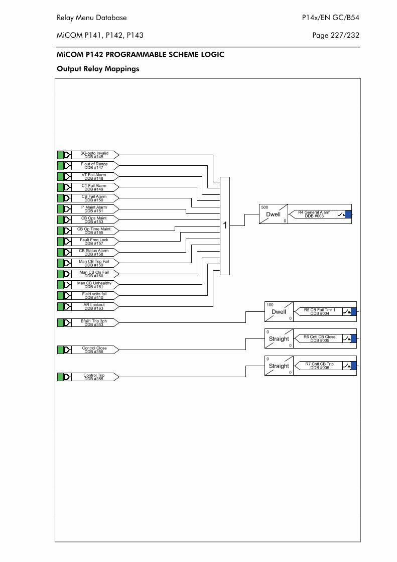
Relay Menu Database P14x/EN GC/B54
MiCOM P141, P142, P143 Page 227/232
MiCOM P142 PROGRAMMABLE SCHEME LOGIC
Output Relay Mappings
��������'0$!�� �;� 9
��������*�,��:����(�
�������"5��*� �%��3
�������&+��*� �%��3
��������+��*� �%��3
�������� <�=� ���%��3
��������+��>!��=� ��
��������+��>!�� 3��=� ��
��������*�,��*��?����
�������"+��'���,��%��3
�������&=���+���� !�*�
��������=���+��+��*�
��������=���+��@�)���)4
��������* �9�;���:�
��������%�����,�
��8�
���
�
���0������%��3��������
���������:� ���� !��!)
��������+����+��
��������+������ !
�8����
�
���+��*� ��3�����������
'��� ()��
�
���+���+��+����������
'��� ()��
�
���+���+���� !��������
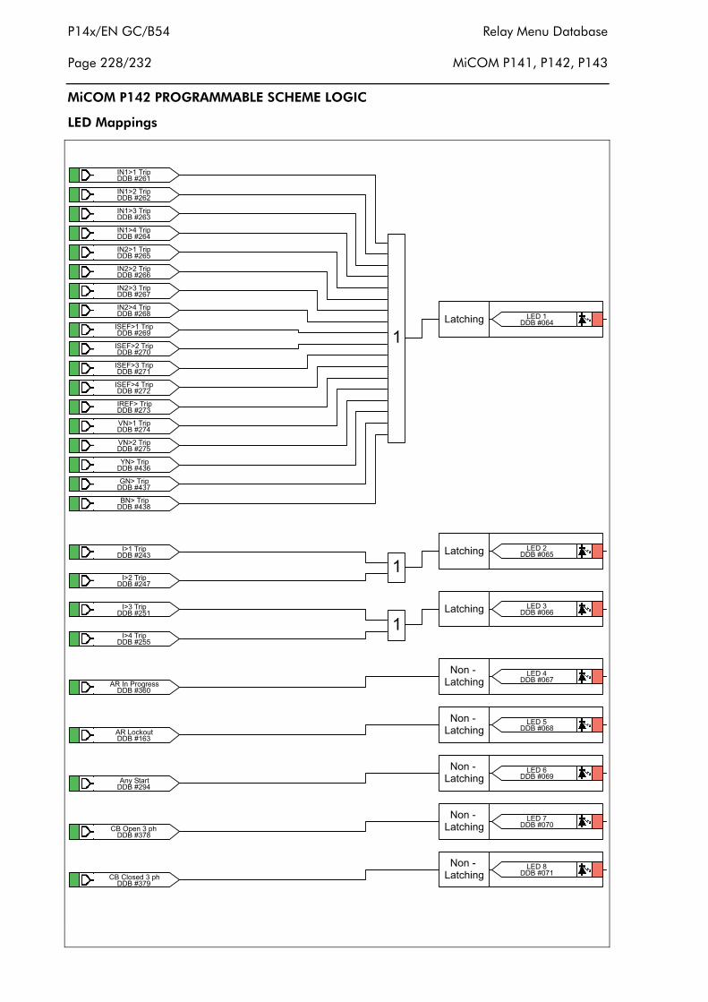
P14x/EN GC/B54 Relay Menu Database
Page 228/232 MiCOM P141, P142, P143
MiCOM P142 PROGRAMMABLE SCHEME LOGIC
LED Mappings
�����#�� ������� !
�����#�# ���#��� !
�����#�� ������� !
�����#�� ������� !
�����#�� �#����� !
�����#�� �#�#��� !
�����#�� �#����� !
�����#�" �#����� !
�����#�& '�*����� !
�����#�� '�*�#��� !
�����#�� '�*����� !
�����#�# '�*����� !
�����#�� ��*���� !
�����#��5������ !
�����#��5��#��� !
��������7����� !
��������0����� !
�������"������ !
�������������) �( �����
�����#�� ����� !
�����#�� �#��� !
�����#�� ����� !
�����#�� ����� !
��������%�� ��1�(����
��������%�����,�
�����#&�%�4�'����
�������"+��>!�����!)
�������&+��+��9���!)
�
�
������������) �( ����#
������������) �( �����
�����������$
����) �(�����
�������"���$
����) �(�����
�������&���$
����) �(�����
�����������$
����) �(�����
�����������$
����) �(����"
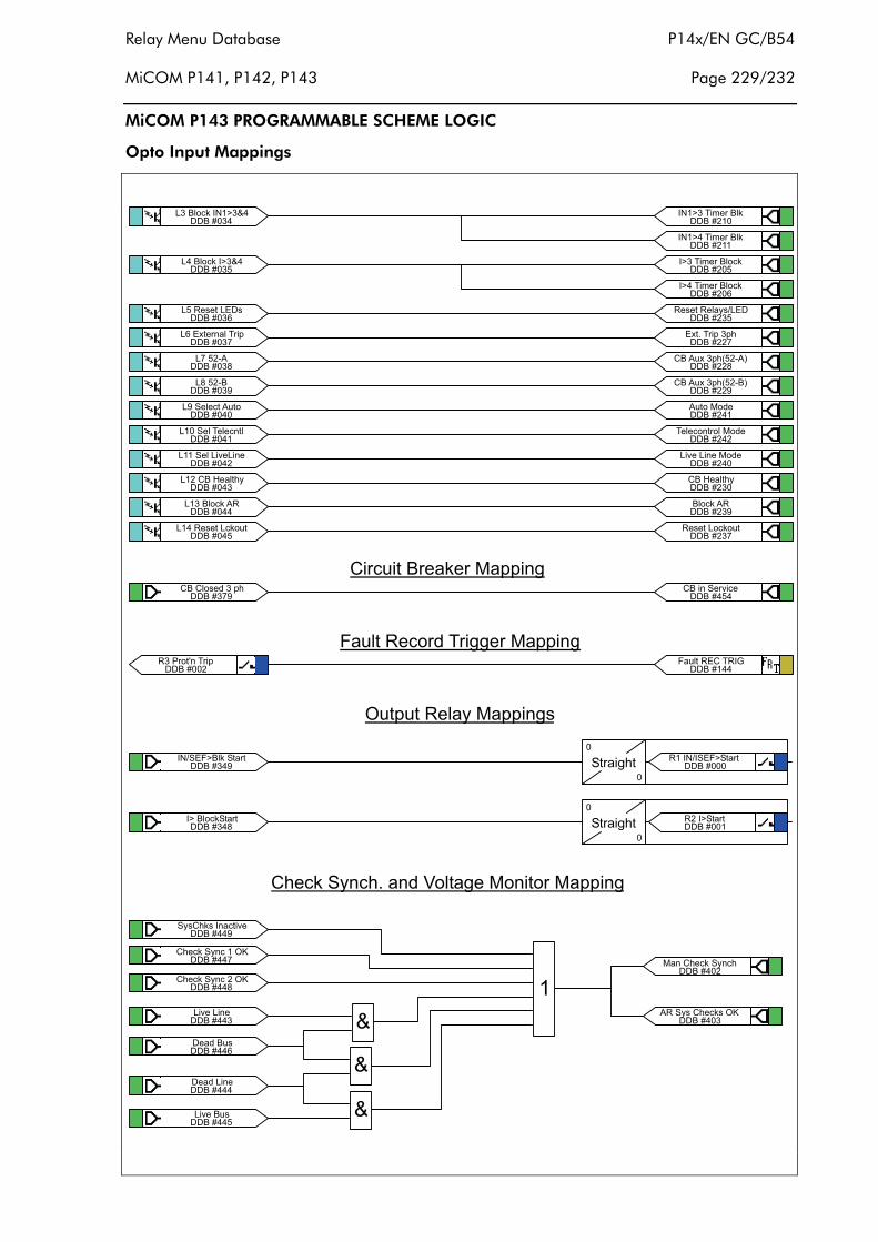
Relay Menu Database P14x/EN GC/B54
MiCOM P141, P142, P143 Page 229/232
MiCOM P143 PROGRAMMABLE SCHEME LOGIC
Opto Input Mappings
>,�!,�����4�=�!! �(�
*�,������9��� ((���=�!! �(
��������������� ������
��������������� ����
���������������������
��������������������� !
�������"����#$%
�������&�"��#$�
���������&�'�����%,�
������������'��������
�������#����'��� ;�� ��
����������#�+��A���)4
����������������%�
���������������������,�
'��� ()��
�
��� �� '�*�'������������
'��� ()��
�
�#� �'������������
�����#�����������,�
�����##"+��%,���!)-�#$%.
�����#��� ;��� ���=9�
�����#�&����%�
�����##����/��� !��!)
��������*�,����+��� 0
�����##&+��%,���!)-�#$�.
�����#��%,��=9�
�����#�#��������=9�
�����#��+��A���)4
�������& ��'�*����'����
�������" �����'����
�������#���1��2���� !
�����#�����������4�����
�����#�� ���� 3������
�����#�� ���� 3������
�����#�� ������ 3�����
�����#�� ������ 3�����
�������&+��+��9���!)
��������+�� ��'��; ��
+ ��, ����������=�!! �(
�������&'4�+)��� ���� ;�
��������+)����'4�����>B
�������"+)����'4���#�>B
��������� ;��� ��
�����������9��,�
�����������9�� ��
��������� ;���,� �
�
�
��������#
=���+)����'4��)
��������%��'4��+)�����>B
+)����'4��)/���9�5��(��=� ���=�!! �(
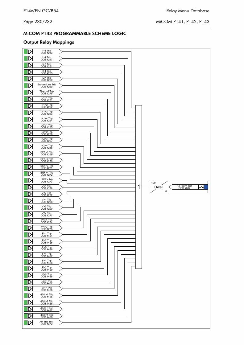
P14x/EN GC/B54 Relay Menu Database
Page 230/232 MiCOM P141, P142, P143
MiCOM P143 PROGRAMMABLE SCHEME LOGIC
Output Relay Mappings
�����#�� ����� !
�����#�� �#��� !
�����#�� ����� !
�����#�� ����� !
�����#�& #���� !
�����#��������� ����� !
�����#���)��3���� !
�����#�� ������� !
�����#�# ���#��� !
�����#�� ������� !
�����#�� ������� !
�����#�� �#����� !
�����#�� �#�#��� !
�����#�� �#����� !
�����#�" �#����� !
�����#�& '�*����� !
�����#�� '�*�#��� !
�����#�� '�*����� !
�����#�# '�*����� !
�����#�� ��*���� !
�����#�"56���� !
�����#"#56#��� !
�����#"�5����� !
�����#��5#���� !
�����#��5������ !
�����#��5��#��� !
������#�*6���� !
������#�*6#��� !
������#�*6���� !
������#�*6���� !
������#"*����� !
������#&*�#��� !
��������7����� !
��������0����� !
�������"������ !
�������#%���� !�����
� �8����
�
���1��2���� !�������#
�����#&�5�#��� !
������"�9:�9������ !
������"�9:�9��#��� !
������"�9:�9������ !
������""9:�9������ !
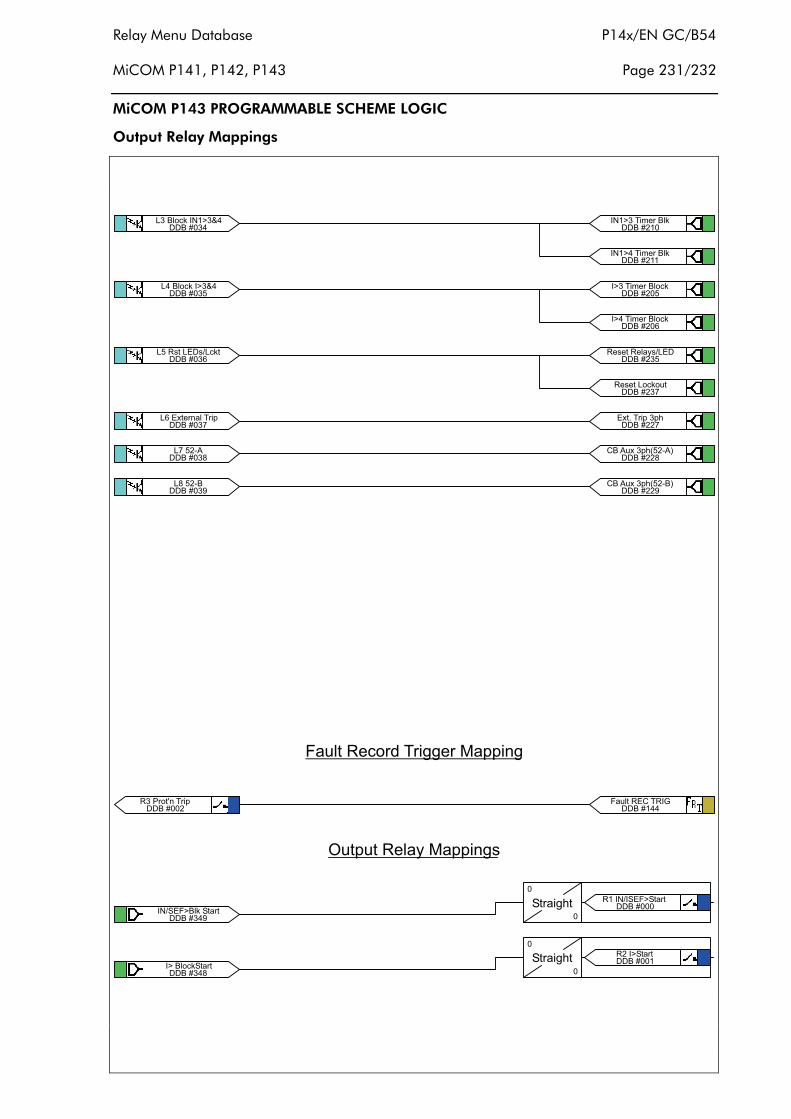
Relay Menu Database P14x/EN GC/B54
MiCOM P141, P142, P143 Page 231/232
MiCOM P143 PROGRAMMABLE SCHEME LOGIC
Output Relay Mappings
��������������� ��
������������������������ �
��������������� ������
��������������� ����
������������������������
��������������������� !
�������"����#$%
�������&�"��#$�
'��� ()��
�
��� �� '�*�'������������
'��� ()��
�
�#� �'������������
�����##"+��%,���!)-�#$%.
�����##����/��� !��!)
��������*�,����+��� 0
�����##&+��%,���!)-�#$�.
�������& ��'�*����'����
�������" �����'����
�������#���1��2���� !
�����#�� ������ 3�����
�����#�� ������ 3�����
�����#�� ���� 3������
�����#�� ���� 3������
�����#�����������4�����
�����#�����������,�
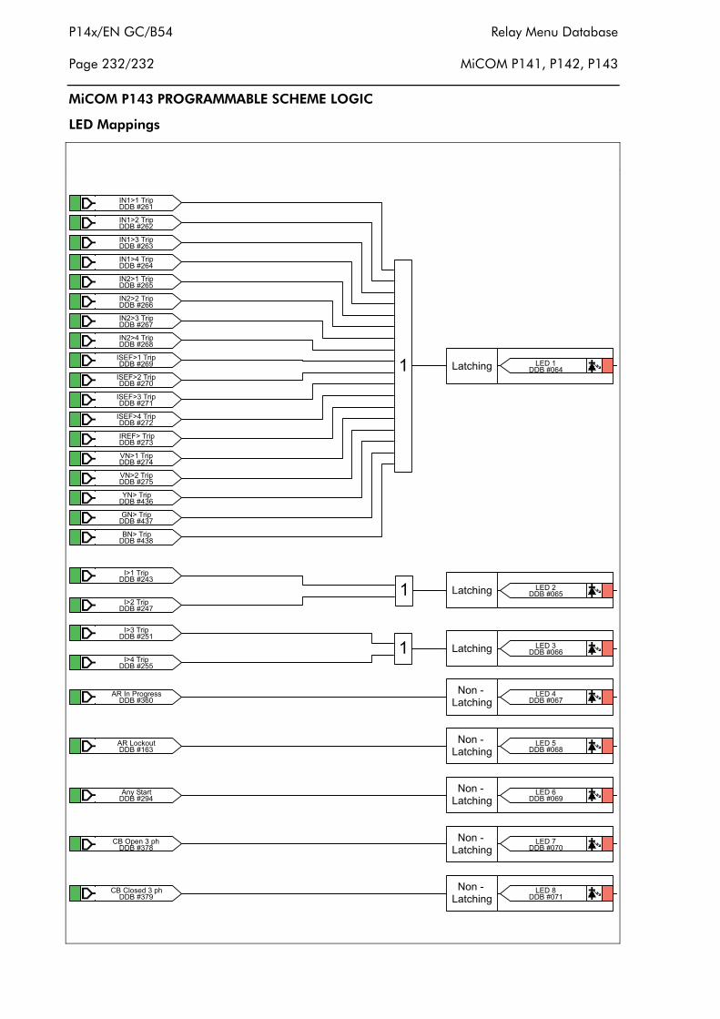
P14x/EN GC/B54 Relay Menu Database
Page 232/232 MiCOM P141, P142, P143
MiCOM P143 PROGRAMMABLE SCHEME LOGIC
LED Mappings
�����#�� ������� !
�����#�# ���#��� !
�����#�� ������� !
�����#�� ������� !
�����#�� �#����� !
�����#�� �#�#��� !
�����#�� �#����� !
�����#�" �#����� !
�����#�& '�*����� !
�����#�� '�*�#��� !
�����#�� '�*����� !
�����#�# '�*����� !
�����#�� ��*���� !
�����#��5������ !
�����#��5��#��� !
��������7����� !
��������0����� !
�������"������ !
� ������������) �( �����
�����#�� ����� !
�����#�� �#��� !
�����#�� ����� !
�����#�� ����� !
��������%�� ��1�(����
��������%�����,�
�����#&�%�4�'����
�������"+��>!�����!)
�������&+��+��9���!)
�
�
������������) �( ����#
������������) �( �����
�����������$
����) �(�����
�������"���$
����) �(�����
�������&���$
����) �(�����
�����������$
����) �(�����
�����������$
����) �(����"
External Connection P14x/EN CO/C54 Diagrams MiCOM P141, P142, P143
EXTERNAL CONNECTION DIAGRAMS

P14x/EN CO/C54 External Connection Diagrams MiCOM P141, P142, P143
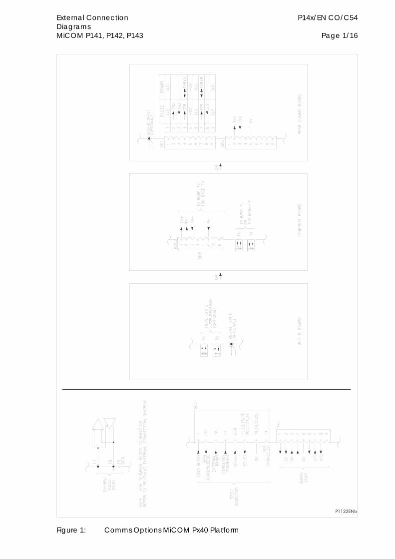
External Connection P14x/EN CO/C54 Diagrams MiCOM P141, P142, P143 Page 1/16
��������
Figure 1: Comms Options MiCOM Px40 Platform
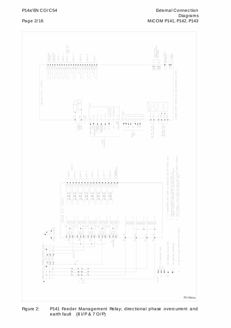
P14x/EN CO/C54 External Connection Diagrams Page 2/16 MiCOM P141, P142, P143
�����
Figure 2: P141 Feeder Management Relay; directional phase overcurrent and earth fault (8 /P & 7 O/P)
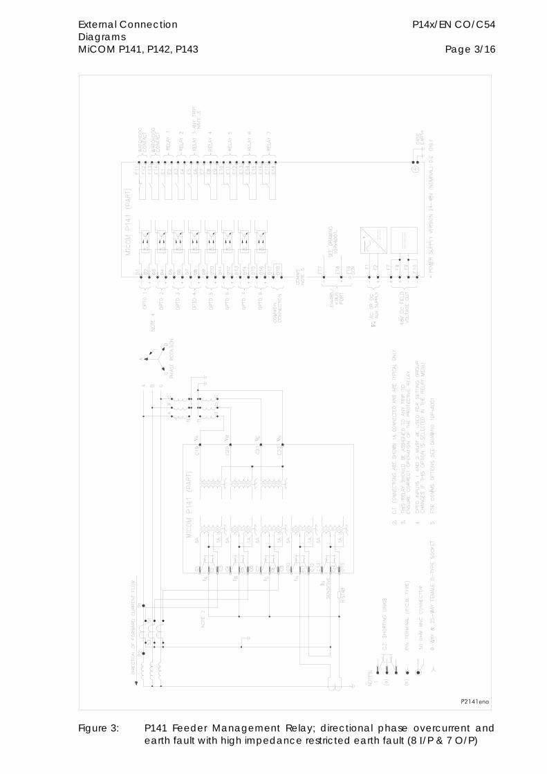
External Connection P14x/EN CO/C54 Diagrams MiCOM P141, P142, P143 Page 3/16
������
Figure 3: P141 Feeder Management Relay; directional phase overcurrent and earth fault with high impedance restricted earth fault (8 /P & 7 O/P)
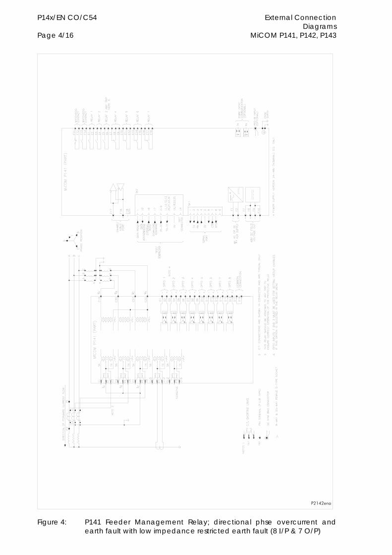
P14x/EN CO/C54 External Connection Diagrams Page 4/16 MiCOM P141, P142, P143
������
Figure 4: P141 Feeder Management Relay; directional phse overcurrent and earth fault with low impedance restricted earth fault (8 /P & 7 O/P)
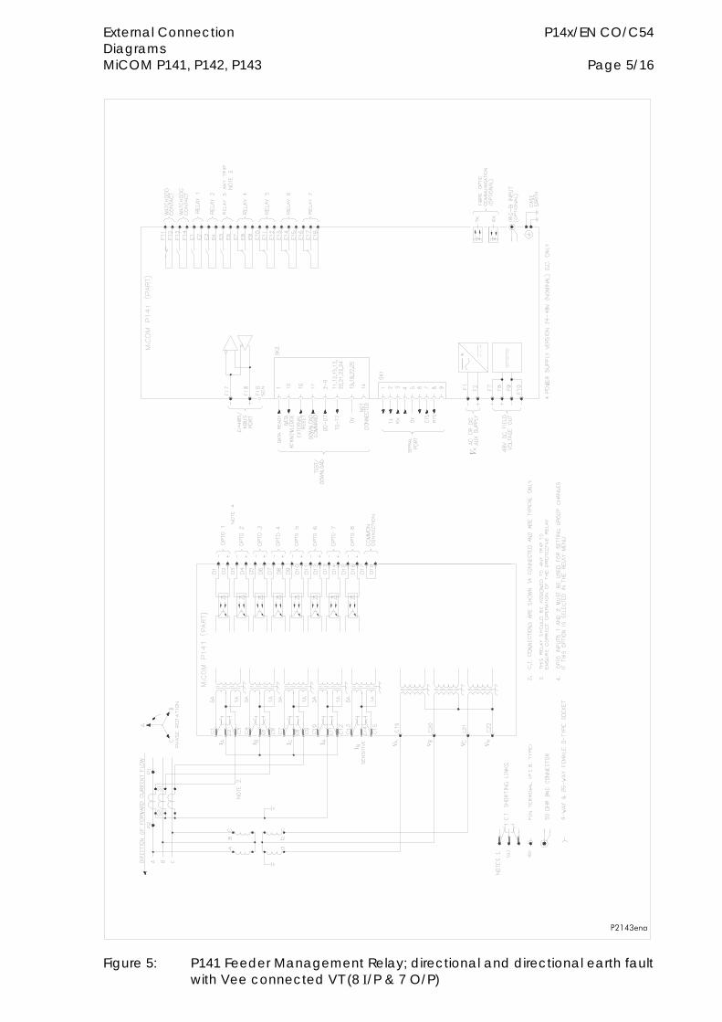
External Connection P14x/EN CO/C54 Diagrams MiCOM P141, P142, P143 Page 5/16
������
Figure 5: P141 Feeder Management Relay; directional and directional earth fault with Vee connected VT (8 /P & 7 O/P)
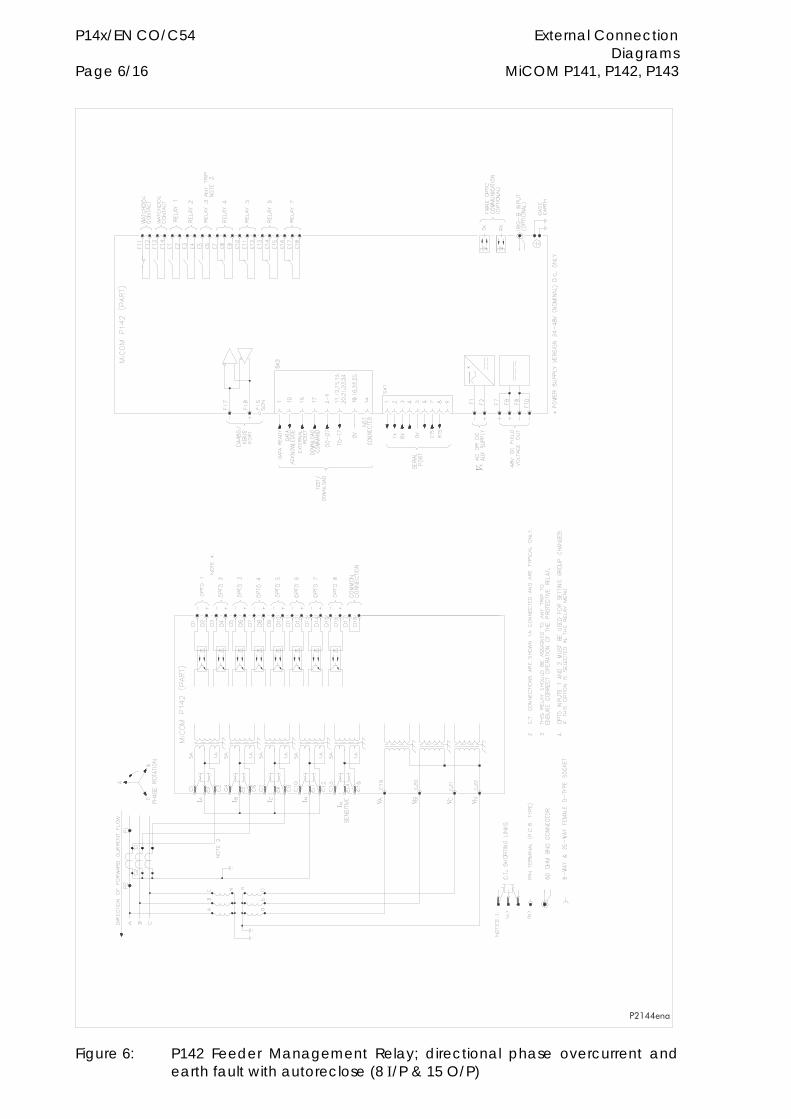
P14x/EN CO/C54 External Connection Diagrams Page 6/16 MiCOM P141, P142, P143
�����
Figure 6: P142 Feeder Management Relay; directional phase overcurrent and earth fault with autoreclose (8 /P & 15 O/P)
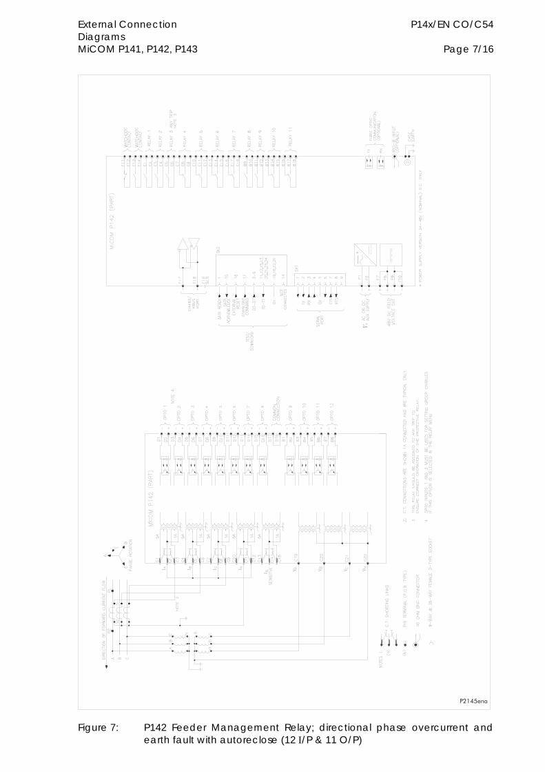
External Connection P14x/EN CO/C54 Diagrams MiCOM P141, P142, P143 Page 7/16
������
Figure 7: P142 Feeder Management Relay; directional phase overcurrent and earth fault with autoreclose (12 /P & 11 O/P)
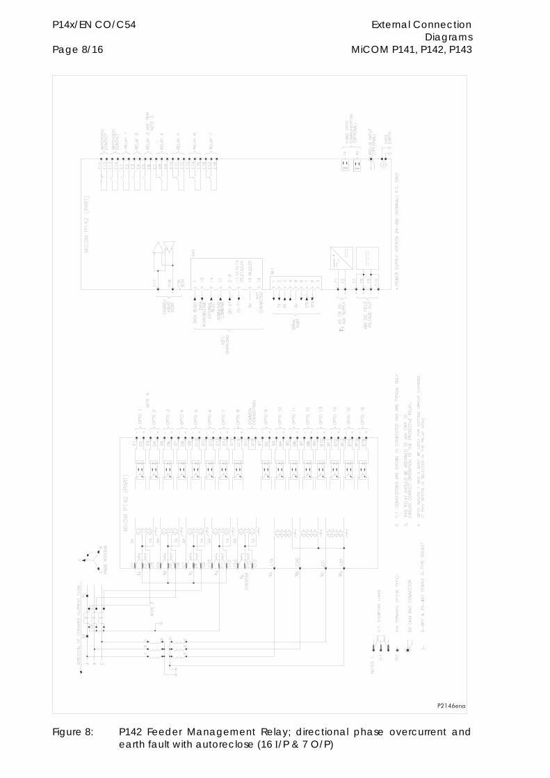
P14x/EN CO/C54 External Connection Diagrams Page 8/16 MiCOM P141, P142, P143
������
Figure 8: P142 Feeder Management Relay; directional phase overcurrent and earth fault with autoreclose (16 /P & 7 O/P)

External Connection P14x/EN CO/C54 Diagrams MiCOM P141, P142, P143 Page 9/16
������
Figure 9: P142 Feeder Management Relay; directional phase overcurrent and earth fault with autoreclose (8 /P & 15 O/P)
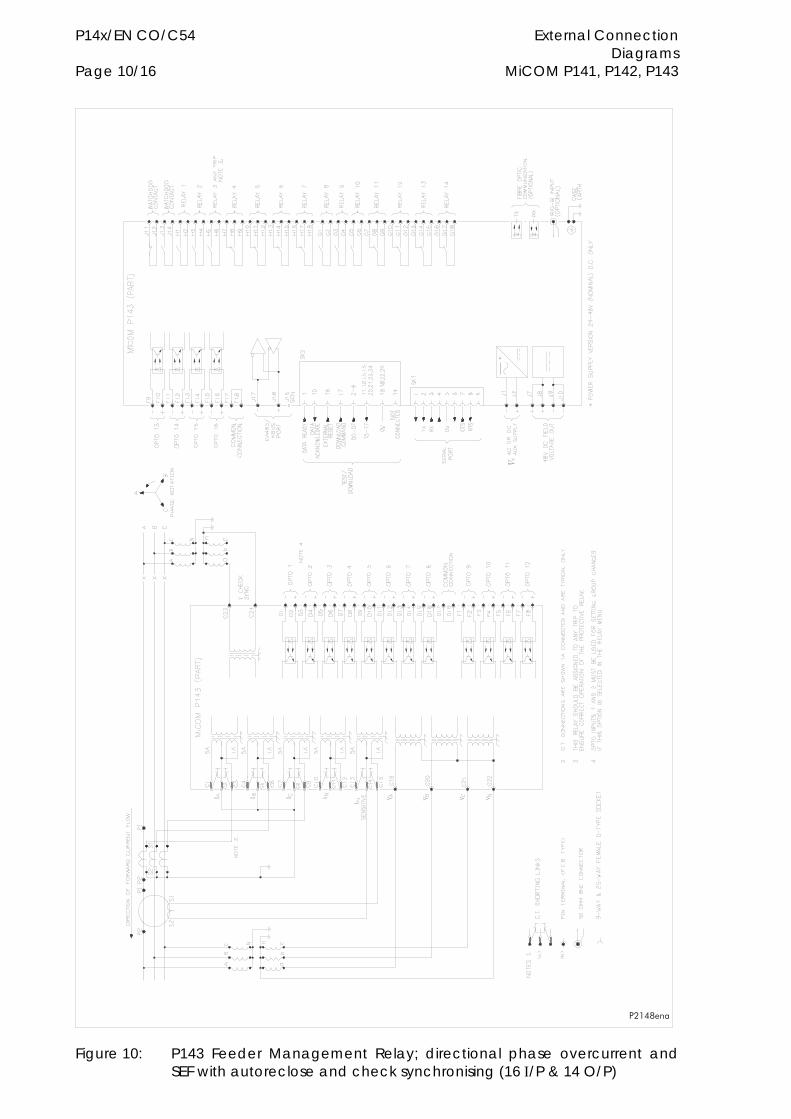
P14x/EN CO/C54 External Connection Diagrams Page 10/16 MiCOM P141, P142, P143
������
Figure 10: P143 Feeder Management Relay; directional phase overcurrent and SEF with autoreclose and check synchronising (16 /P & 14 O/P)
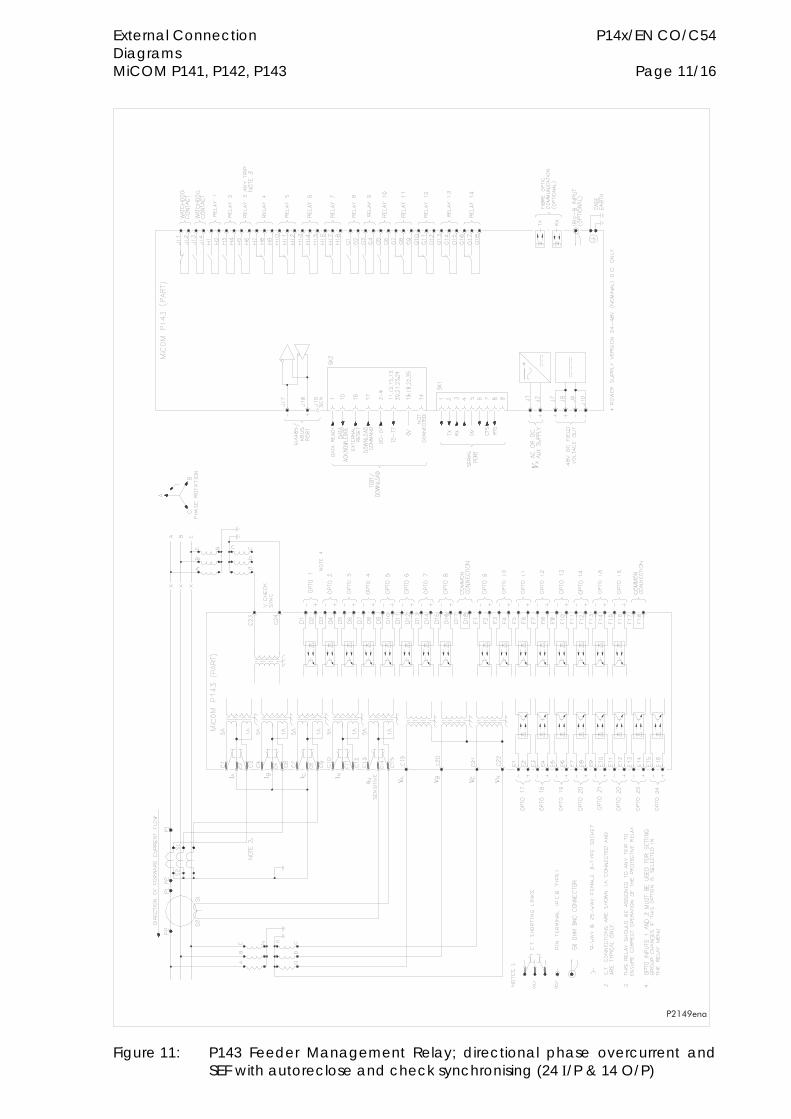
External Connection P14x/EN CO/C54 Diagrams MiCOM P141, P142, P143 Page 11/16
������
Figure 11: P143 Feeder Management Relay; directional phase overcurrent and SEF with autoreclose and check synchronising (24 /P & 14 O/P)
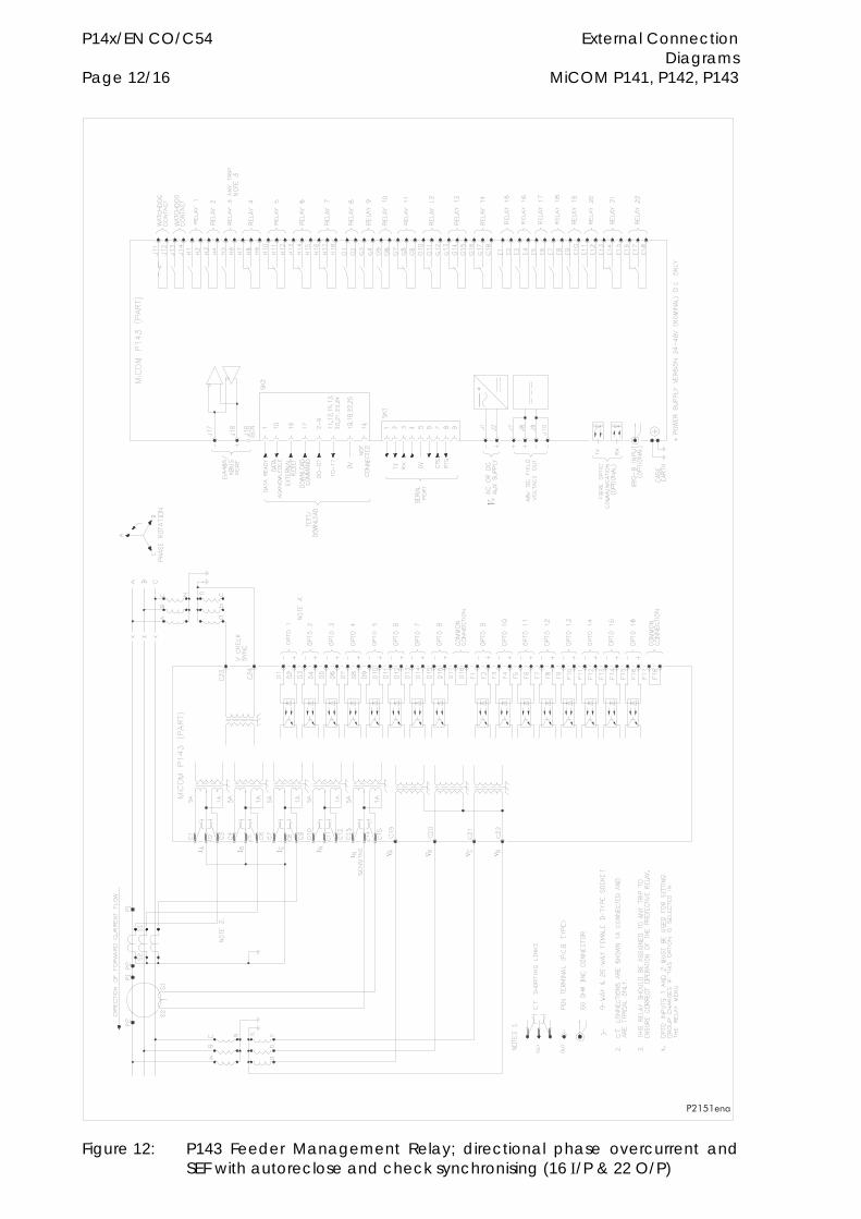
P14x/EN CO/C54 External Connection Diagrams Page 12/16 MiCOM P141, P142, P143
�������
Figure 12: P143 Feeder Management Relay; directional phase overcurrent and SEF with autoreclose and check synchronising (16 /P & 22 O/P)
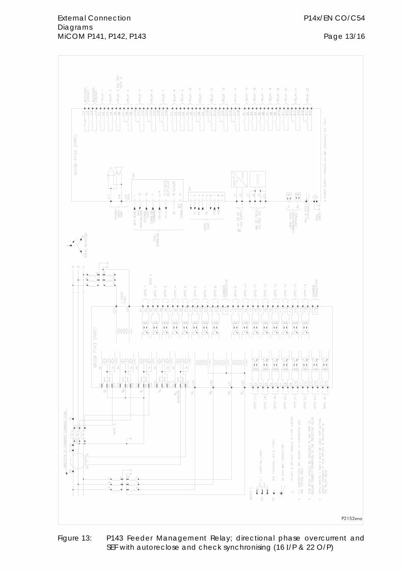
External Connection P14x/EN CO/C54 Diagrams MiCOM P141, P142, P143 Page 13/16
�������
Figure 13: P143 Feeder Management Relay; directional phase overcurrent and SEF with autoreclose and check synchronising (16 /P & 22 O/P)
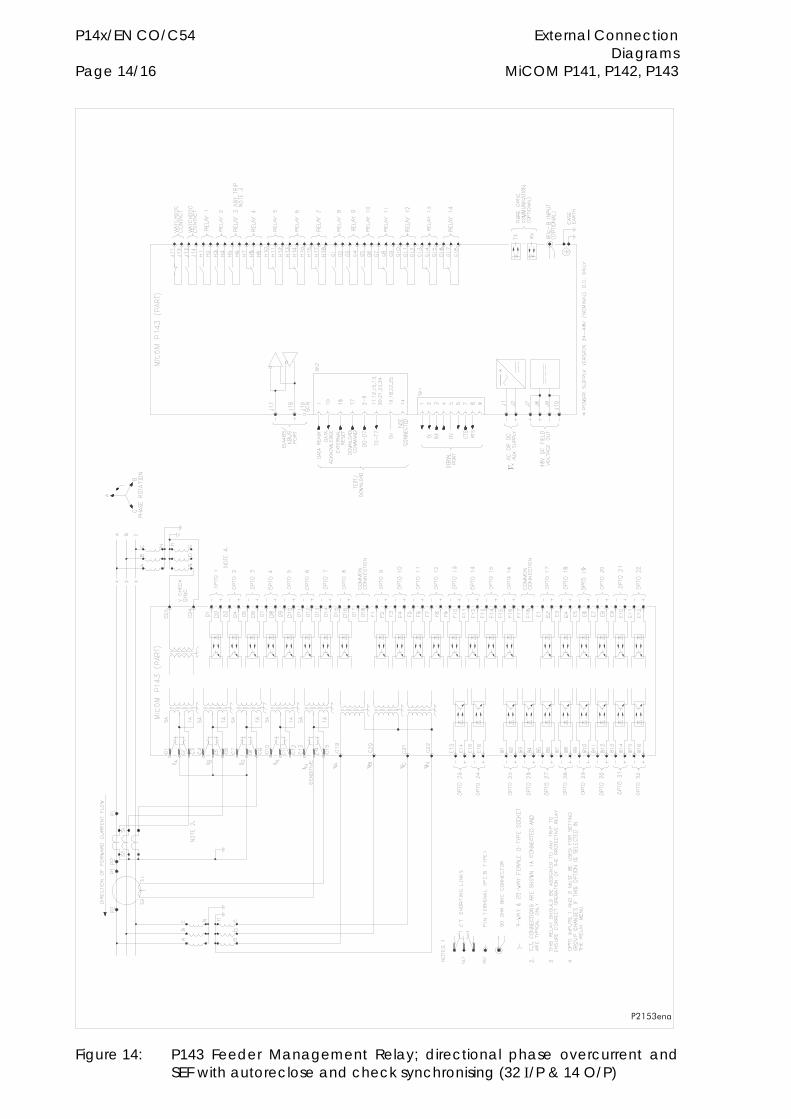
P14x/EN CO/C54 External Connection Diagrams Page 14/16 MiCOM P141, P142, P143
�������
Figure 14: P143 Feeder Management Relay; directional phase overcurrent and SEF with autoreclose and check synchronising (32 /P & 14 O/P)
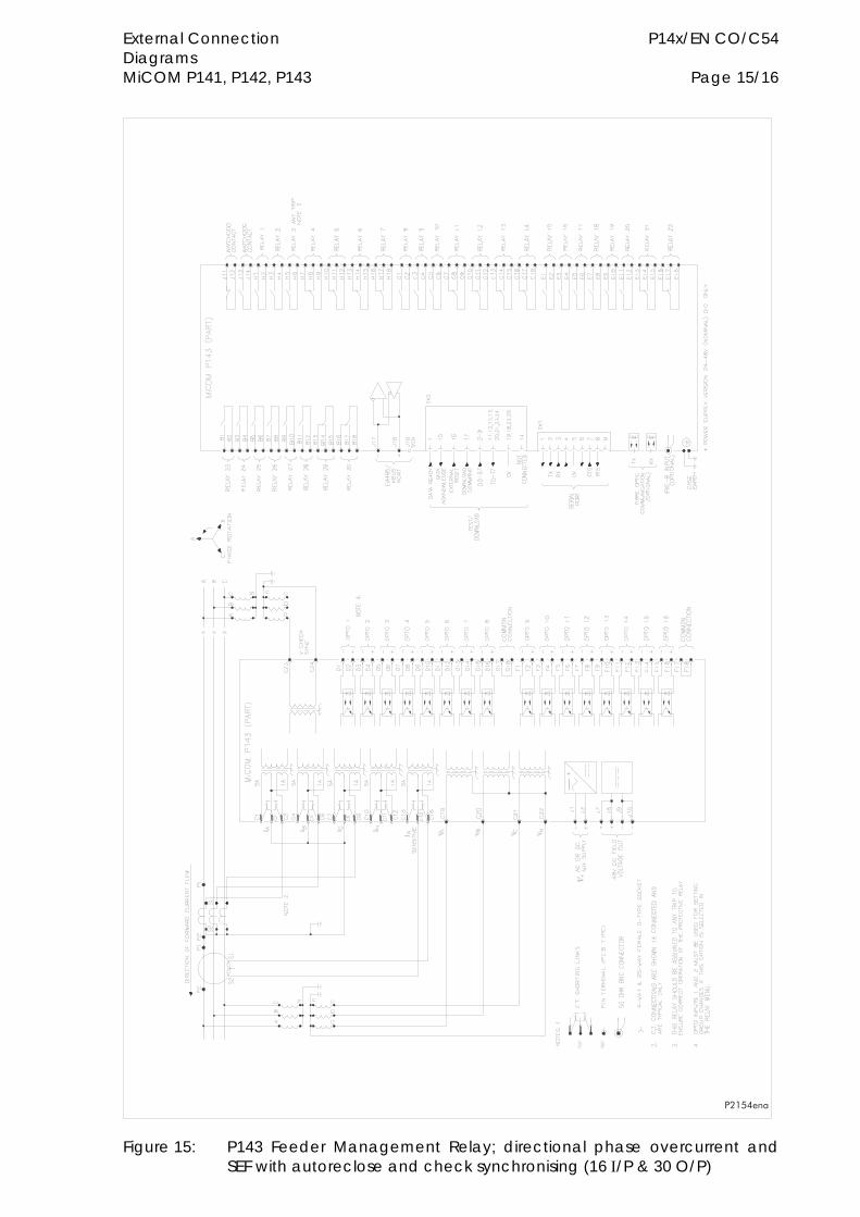
External Connection P14x/EN CO/C54 Diagrams MiCOM P141, P142, P143 Page 15/16
������
Figure 15: P143 Feeder Management Relay; directional phase overcurrent and SEF with autoreclose and check synchronising (16 /P & 30 O/P)

P14x/EN CO/C54 External Connection Diagrams Page 16/16 MiCOM P141, P142, P143

Autoreclose Diagrams P14x/EN LG/C54 MiCOM P141, P142, P143
AUTORECLOSE DIAGRAMS
P14x/EN LG/C54 Autoreclose Diagrams MiCOM P141, P142, P143
MiCOM P141, P142, P143
Feeder Management Relays
Autoreclose Diagrams
Scheme 1 - refers to P142 autoreclose logic
Scheme 2 - refers to P143 autoreclose logic
Autoreclose Diagrams P14x/EN LG/C54 MiCOM P141, P142, P143 Page 1/14
CONTENT
Figure 1: “Protection Start” signals 3
Figure 2: Auto-reclose blocking logic 4
Figure 3: AR initiation and sequence counter 5
Figure 4: “Block Instantaneous Protection” for selected trips 6
Figure 5: “Block Instantaneous Protection” for AR unavailable or maintenance/EFF lockout 7
Figure 6: Dead time control 8
Figure 7: AR CB close control 8
Figure 8: System checks 9
Figure 9: Circuit breaker control 10
Figure 10: Reclaim time / AR successful logic 11
Figure 11: Overall AR lockout logic 12
Figure 12: Lockout for protection trip when AR not available 13
Figure 13: AR reset lockout 13
Figure 14: Shots exceeded logic 13
Figure 15: AR Initiation inhibit 14
Figure 16: System checks functional logic diagram 14

P14x/EN LG/C54 Autoreclose Diagrams Page 2/14 MiCOM P141, P142, P143
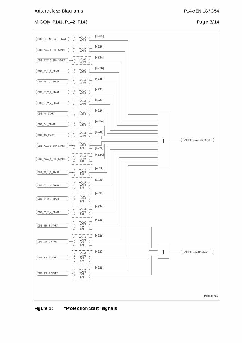
Autoreclose Diagrams P14x/EN LG/C54 MiCOM P141, P142, P143 Page 3/14
�������
�
����
����
����
����
����
����
����
����
����
����
����
����
����
����
����
����
����
����
����
����
����������
����������������
����������������
����������������
����������������
������������
���� �������
������������
������������!������
������������!������
����������������
����������������
����������������
����������������
���������������
���������������
���������������
���������������
������������!������
������������!������ ����������
����������
����������
�����"���������������
����������
����������
����������
����������
����������
����������
�������������
�������������
�������������
�������������
�������������
�������������
����������������
����������������
����������������
����������������
����#$�%&'��%#�()$�$($
����#$�%&'�����()$�$($�
Figure 1: “Protection Start” signals
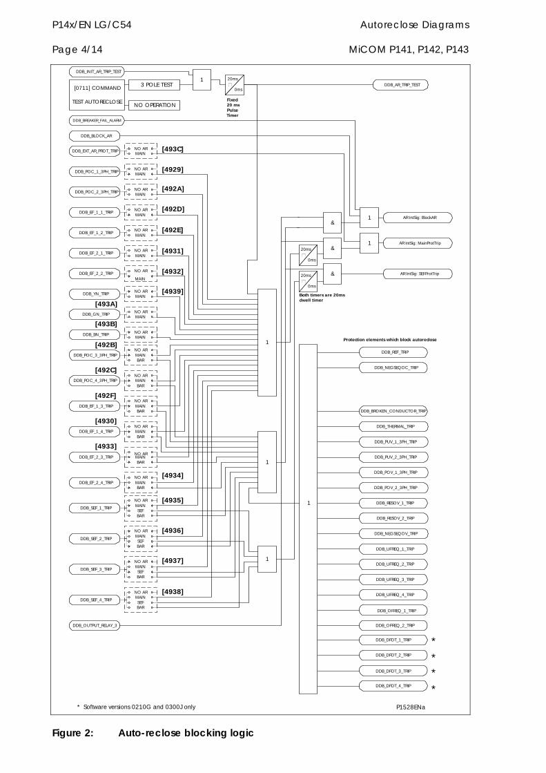
P14x/EN LG/C54 Autoreclose Diagrams Page 4/14 MiCOM P141, P142, P143
[0711] COMMAND
TEST AUTORECLOSENO OPERATION
3 POLE TEST DDB_AR_TRIP_TEST
DDB_EXT_AR_PROT_TRIP
NO ARMAINSEFBAR
NO ARMAINBAR
NO ARMAIN
DDB_POC_1_3PH_TRIPNO ARMAIN
DDB_POC_2_3PH_TRIPNO ARMAIN
DDB_POC_3_3PH_TRIP
DDB_POC_4_3PH_TRIP
DDB_EF_1_1_TRIPNO ARMAIN
DDB_EF_1_2_TRIPNO ARMAIN
DDB_EF_1_3_TRIP
DDB_EF_1_4_TRIP
DDB_EF_2_1_TRIPNO ARMAIN
DDB_EF_2_2_TRIPNO AR
MAIN
DDB_EF_2_3_TRIP
DDB_EF_2_4_TRIP
NO ARMAINBAR
NO ARMAINBAR
NO ARMAINBAR
NO ARMAINBAR
NO ARMAIN
DDB_YN_TRIP
NO ARMAIN
DDB_GN_TRIP
NO ARMAIN
DDB_BN_TRIP
DDB_SEF_1_TRIP
NO ARMAINSEFBAR
DDB_SEF_2_TRIP
NO ARMAINSEFBAR
DDB_SEF_3_TRIP
NO ARMAINSEFBAR
DDB_SEF_4_TRIP
1
1
1
NO ARMAINBAR
DDB_OUTPUT_RELAY_3
DDB_BLOCK_AR
DDB_BREAKER_FAIL_ALARM
1
DDB_REF_TRIP
DDB_NEGSEQOC_TRIP
DDB_BROKEN_CONDUCTOR_TRIP
DDB_THERMAL_TRIP
DDB_PUV_1_3PH_TRIP
DDB_PUV_2_3PH_TRIP
DDB_POV_1_3PH_TRIP
DDB_POV_2_3PH_TRIP
DDB_RESOV_1_TRIP
DDB_RESOV_2_TRIP
DDB_NEGSEQOV_TRIP
DDB_UFREQ_1_TRIP
DDB_UFREQ_2_TRIP
DDB_UFREQ_3_TRIP
DDB_UFREQ_4_TRIP
DDB_OFREQ_1_TRIP
DDB_OFREQ_2_TRIP
DDB_INIT_AR_TRIP_TEST
1
[493C]
[4929]
[492A]
[492D]
[492E]
[4931]
[4932]
[4939]
[493B]
[492B]
[492C]
[492F]
[4930]
[4933]
[4934]
[4935]
[4936]
[4937]
[4938]
[493A]
&AR IntSig: MainProtTrip1
&
&
1 AR IntSig: BlockAR
AR IntSig: SEFProtTrip
20ms
0ms
Fixed20 msPulseTimer
Both timers are 20msdwell timer
20ms
0ms
20ms
0ms
DDB_DFDT_1_TRIP
DDB_DFDT_2_TRIP
DDB_DFDT_3_TRIP
DDB_DFDT_4_TRIP
Protection elements which block autoreclose
P1528ENa* Software versions 0210G and 0300J only
*
*
*
*
Figure 2: Auto-reclose blocking logic
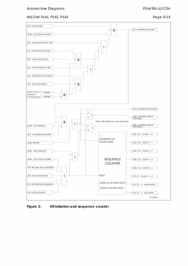
Autoreclose Diagrams P14x/EN LG/C54 MiCOM P141, P142, P143 Page 5/14
�������
���'�����*��+�,���*���
���'��,�������
���'����������������������
���'�����������������������
���'���������������������
���'����������������������
���'������!� !��!���
���'�������!� !��!���
����*�
�����*�
-
�
�
�.
���'����'�/0������!���
��.,������,����
���'����'�/0�������!���
���'����'���,���/0��
���'�����'���,���0��
���'�����'���,���0��
���'�����'���,���0��
���'�����'���,���0��
���'�����'���,���0��
��������������**�� ��� �
�����
���� ��)����������!���
���� ��)���������!���
�)$1'��22�2$3415�(1�(151$�6)7%##$
�
�.
���'���,�����*��������� ������
���'���,�����*��������� ����
���'��,�����*������������
���� ������� '
��.,����
������������
���'��,�����*���������
-
-
�
�
-
�
�
-
���'���,�����*������!����
���'��������
���'�����*��+�,���*���
���'����*�������������*���
���'������,�������
���'��,�����*���������*��
���'�*�8��*��������
���'����������*���
���'�����������8���
Figure 3: AR initiation and sequence counter
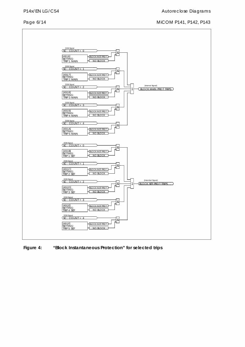
P14x/EN LG/C54 Autoreclose Diagrams Page 6/14 MiCOM P141, P142, P143
DDB Signal
[491F]SETTING:TRIP 5 SEF
[491E]SETTING:TRIP 4 SEF
[491D]SETTING:TRIP 3 SEF
[491C]SETTING:TRIP 2 SEF
[491B]SETTING:TRIP 1 SEF
NO BLOCK
NO BLOCK
BLOCK INST PROT
NO BLOCK
BLOCK INST PROT
SC : COUNT = 4
DDB Signal
DDB Signal
SC : COUNT = 3
&
&
NO BLOCK
BLOCK INST PROT
NO BLOCK
BLOCK INST PROT
BLOCK INST PROT
DDB Signal
SC : COUNT = 2
SC : COUNT = 0
DDB Signal
SC : COUNT = 1
&
&
&
[4916]SETTING:TRIP 1 MAIN
[4917]SETTING:TRIP 2 MAIN
[4918]SETTING:TRIP 3 MAIN
[4919]SETTING:TRIP 4 MAIN
[491A]SETTING:TRIP 5 MAIN
BLOCK INST PROT
NO BLOCK
NO BLOCK
BLOCK INST PROT
NO BLOCK
BLOCK INST PROT
DDB Signal
SC : COUNT = 4
DDB Signal
SC : COUNT = 3
&
&
NO BLOCK
BLOCK INST PROT
NO BLOCK
BLOCK INST PROT
SC : COUNT = 1
DDB Signal
SC : COUNT = 2
DDB Signal
DDB Signal
SC : COUNT = 0
&
&
&
BLOCK SEF PROT TRIPS1(Internbal Signal)
BLOCK MAIN PROT TRIPS1(Internal Signal)
Figure 4: “Block Instantaneous Protection” for selected trips
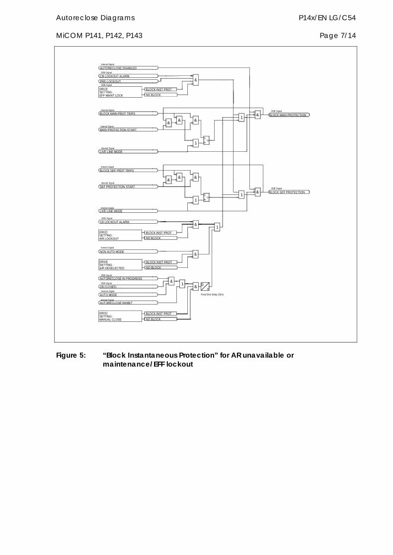
Autoreclose Diagrams P14x/EN LG/C54 MiCOM P141, P142, P143 Page 7/14
S
R
S
R
Fixed time delay 20msAUTO MODE
AUTORECLOSE INHIBIT
AUTORECLOSE IN PROGRESS
CB CLOSED
NON AUTO MODE
LIVE LINE MODE
CB LOCKOUT ALARM
Internal Signal
DDB Signal
Internal Signal
Internal Signal
Internal Signal
DDB Signal
DDB Signal
[4912]SETTING :A/R LOCKOUT
[4914]SETTING :A/R DESELECTED
[4915]SETTING :MANUAL CLOSE
BLOCK INST PROT
NO BLOCK
BLOCK INST PROT
NO BLOCK
&1
& 0
BLOCK INST PROT
NO BLOCK
&
1
&
SEF PROTECTION START
BLOCK MAIN PROT TRIPS
BLOCK SEF PROT TRIPS
MAIN PROTECTION START
PRE-LOCKOUT
AUTORECLOSE DISABLED
LIVE LINE MODE
Internal Signal
DDB Signal
DDB Signal
CB LOCKOUT ALARM
[4913]SETTING :EFF MAINT LOCK
Internal Signal
Internal Signal
Internal Signal
Internal Signal
Internal Signal
& &&
1
NO BLOCK
BLOCK INST PROT
&& &
&
1
t
Q
1
BLOCK MAIN PROTECTION
Q
& BLOCK SEF PROTECTIONDDB Signal
1&
DDB Signal
Figure 5: “Block Instantaneous Protection” for AR unavailable or maintenance/EFF lockout
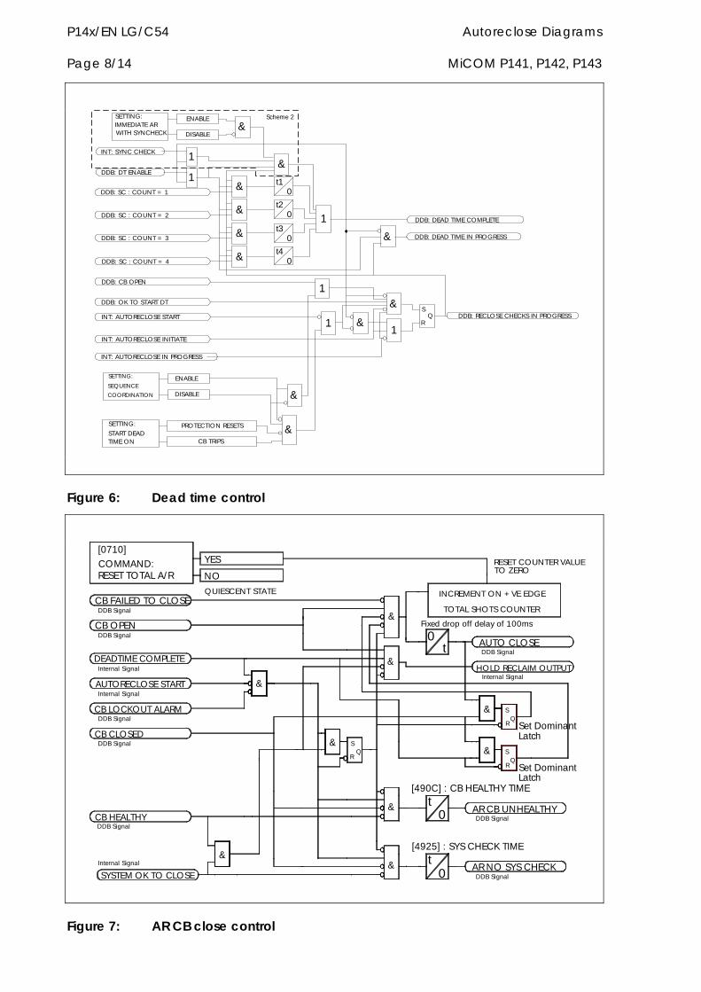
P14x/EN LG/C54 Autoreclose Diagrams Page 8/14 MiCOM P141, P142, P143
Scheme 2
DDB: DEAD TIME IN PROGRESS
DDB: SC : COUNT = 1
DDB: SC : COUNT = 2
DDB: SC : COUNT = 3
DDB: SC : COUNT = 4
DDB: CB OPEN
INT: AUTORECLOSE START
INT: AUTORECLOSE INITIATE
&
&
0t1
0t2
0t3
0t4
1 DDB: DEAD TIME COMPLETE
SETTING:IMMEDIATE ARWITH SYNCHECK
ENABLE
DISABLE&
&INT: SYNC CHECK
DDB: DT ENABLE
1
1
SETTING:
START DEADTIME ON
PROTECTION RESETS
CB TRIPS
&
SETTING:
SEQUENCE
COORDINATION
ENABLE
DISABLE
1
&
1 &1
&DDB: OK TO START DTS
RQ DDB: RECLOSE CHECKS IN PROGRESS
&
&
&
INT: AUTORECLOSE IN PROGRESS
Figure 6: Dead time control
SYSTEM OK TO CLOSE
Internal Signal
CB HEALTHYDDB Signal
DDB Signal
CB CLOSEDDDB Signal
&
&
QUIESCENT STATE
YES
NO
CB OPEN
AUTORECLOSE START
DEADTIME COMPLETE
CB LOCKOUT ALARM
Internal Signal
Internal Signal
DDB Signal
CB FAILED TO CLOSE
[0710]
COMMAND:RESET TOTAL A/R
DDB Signal
&
S
R
&
[490C] : CB HEALTHY TIME
[4925] : SYS CHECK TIME
t0
&
& t0
S
RQ
AR CB UNHEALTHY
AR NO SYS CHECKDDB Signal
DDB Signal
Set DominantLatch
Set DominantLatch
S
RQ
Q
&
TOTAL SHOTS COUNTER
INCREMENT ON + VE EDGE
Fixed drop off delay of 100ms
&
0t
&
HOLD RECLAIM OUTPUT
AUTO CLOSE
Internal Signal
DDB Signal
RESET COUNTER VALUETO ZERO
Figure 7: AR CB close control
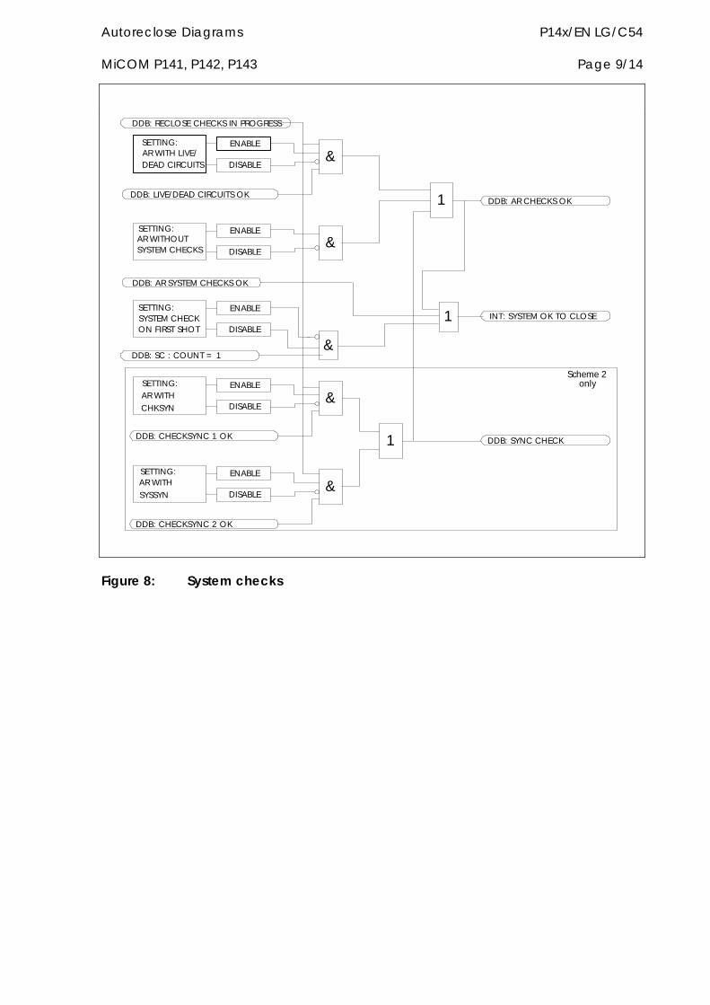
Autoreclose Diagrams P14x/EN LG/C54 MiCOM P141, P142, P143 Page 9/14
DDB: SC : COUNT = 1
SETTING:SYSTEM CHECKON FIRST SHOT
ENABLE
DISABLE
&
1
DDB: AR SYSTEM CHECKS OK
SETTING:AR WITH LIVE/DEAD CIRCUITS
ENABLE
DISABLE
DDB: LIVE/DEAD CIRCUITS OK
SETTING:AR WITHOUTSYSTEM CHECKS
ENABLE
DISABLE
&
1
&
DDB: AR CHECKS OK
INT: SYSTEM OK TO CLOSE
Scheme 2onlySETTING:
AR WITH
CHKSYN
ENABLE
DISABLE
DDB: CHECKSYNC 1 OK
SETTING:AR WITH
SYSSYN
ENABLE
DISABLE
DDB: CHECKSYNC 2 OK
1
&
&
DDB: SYNC CHECK
DDB: RECLOSE CHECKS IN PROGRESS
Figure 8: System checks
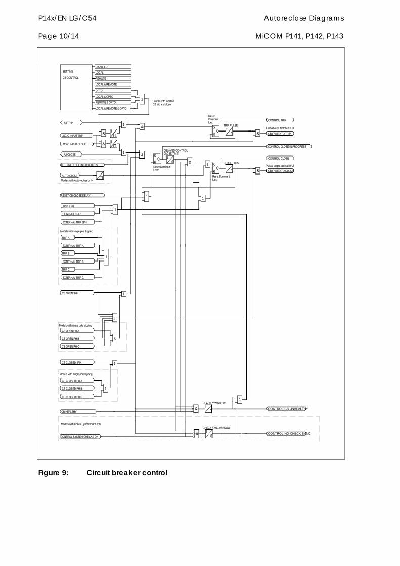
P14x/EN LG/C54 Autoreclose Diagrams Page 10/14 MiCOM P141, P142, P143
&
CONTROL SYSTEM CHECKS OKCONTROL NO CHECK SYNC
CHECK SYNC WINDOW
& t0
EXTERNAL TRIP A
EXTERNAL TRIP C
EXTERNAL TRIP B
Models with single pole tripping
Models with Check Synchronism only
CB CLOSED PH C
CB CLOSED PH B
CB CLOSED PH A
CB CLOSED 3PH
CB HEALTHY
CB OPEN PH B
CB OPEN PH C
CB OPEN 3PH
CB OPEN PH A
Models with single pole tripping
TRIP C
TRIP B
1
1
&
1
1
1
Models with single pole tripping
EXTERNAL TRIP 3PH
Models with Auto-reclose only
AUTO-RECLOSE IN PROGRESS
LOGIC INPUT CLOSE
RESET CB CLOSE DELAY
LOGIC INPUT TRIP
CONTROL TRIP
TRIP 3 PH
AUTO CLOSE
UI CLOSE
SETTING :
CB CONTROL
TRIP A
UI TRIP
1 DELAYED CONTROLCLOSE TIME
1
1
& S
R 0tQ
Reset DominantLatch
&
&
1
LOCAL & REMOTE & OPTO
DISABLED
LOCAL & REMOTE
REMOTE & OPTO
LOCAL & OPTO
LOCAL
REMOTE
OPTO
Enable opto initiatedCB trip and close
&
1
1HEALTHY WINDOW
& t0
CONTROL CB UNHEALTHY
CONTROL CLOSE IN PROGRESS
1
CLOSE PULSES tR
Q0
1
Reset DominantLatch
Pulsed output latched in UI
& CB FAILED TO CLOSE
CONTROL CLOSE
tTRIP PULSES
RQ
0
ResetDominantLatch
Pulsed output latched in UI
& CB FAILED TO TRIP
CONTROL TRIP
Figure 9: Circuit breaker control
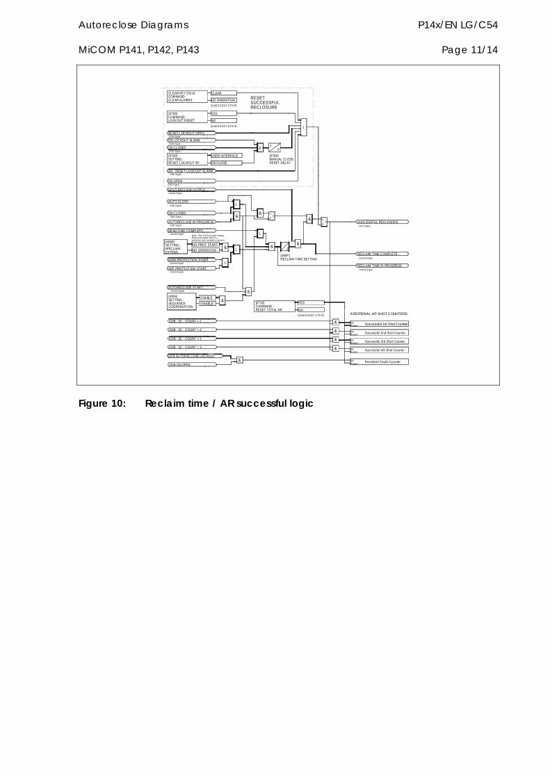
Autoreclose Diagrams P14x/EN LG/C54 MiCOM P141, P142, P143 Page 11/14
t0
[490F] :RECLAIM TIME SETTING
[070A]MANUAL CLOSERESET DELAY
DDB : SC : COUNT = 1
DDB : SC : COUNT = 2
DDB : SC : COUNT = 3
DDB : SC : COUNT = 4
DDB CB OPEN
DDB AUTORECLOSE LOCKOUT
&
&
&
&
& Persistent Faults Counter
Successful 4th Shot Counter
Successful 3rd Shot Counter
Successful 2nd Shot Counter
Successful 1st Shot CounterIncR ese t
IncR ese t
IncR ese t
IncR ese t
IncR ese t
AUTO CLOSE
MAIN PROTECTION START
AUTORECLOSE IN PROGRESS
AUTORECLOSE START
DEAD TIME COMPLETE
SEF PROTECTION START
NO OPERATION
ON PROT START
Note : The "On Prot Start" settingblocks the reclaim timer if a protection start condition is present.
Internal Signal
[4904]SETTING : SEQUENCECOORDINATION
Internal Signal
Internal Signal
Internal Signal
[490E]SETTING : tRECLAIMEXTEND
CB CLOSED
DDB Signal
DDB Signal
DDB Signal
ENABLE
DISABLE&
1
&
[0710]COMMAND :RESET TOTAL AR
&1
&
1
&
1
S
RQ
&
AR : RESET LOCKOUT ALARM
HOLD RECLAIM OUTPUT
RESET LOCKOUT OPTO
CB OPEN
Internal Signal
DDB Signal
DDB Signal
DDB Signal
DDB Signal
[0709]SETTING :RESET LOCKOUT BY
CB CLOSED
[0708]COMMAND :LOCKOUT RESET
CB LOCKOUT ALARMDDB Signal
CLEAR KEY ON UICOMMAND :CLEAR ALARMS
USER INTERFACE
CB CLOSE
t0&
YES
QUIESCENT STATE
NO
NO OPERATION
QUIESCENT STATE
CLEAR
RESETSUCCESSFULRECLOSURE
RECLAIM TIME COMPLETE
RECLAIM TIME IN PROGRESS
SUCCESSFUL RECLOSURE
Internal S ignal
Internal S ignal
ADDITIONAL AR SHOT COUNTERS
YES
QUIESCENT STATE
NO
&
QS
R
&
DD B Signal
1
Figure 10: Reclaim time / AR successful logic
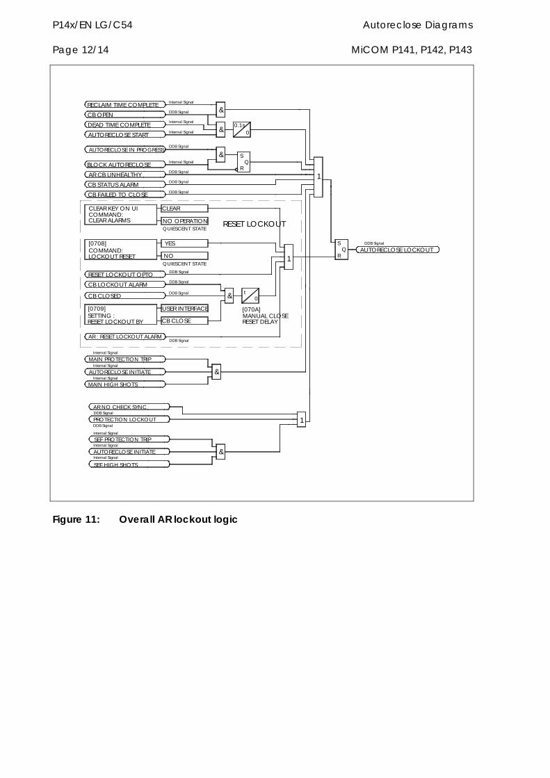
P14x/EN LG/C54 Autoreclose Diagrams Page 12/14 MiCOM P141, P142, P143
RESET LOCKOUT
[070A]MANUAL CLOSERESET DELAY
DDB Signal & t
PROTECTION LOCKOUT
AR : RESET LOCKOUT ALARM
MAIN PROTECTION TRIP
AUTORECLOSE INITIATE
AUTORECLOSE INITIATE
SEF PROTECTION TRIP
AR NO CHECK SYNC
SEF HIGH SHOTS
Internal Signal
Internal Signal
Internal Signal
DDB Signal
DDB Signal
MAIN HIGH SHOTS
Internal Signal
Internal Signal
Internal Signal
[0709]SETTING :RESET LOCKOUT BY
CB CLOSED
&
USER INTERFACE
DDB Signal
CB CLOSE
&
0
RECLAIM TIME COMPLETE
RESET LOCKOUT OPTO
CB FAILED TO CLOSE
DEAD TIME COMPLETE
AUTORECLOSE START
AUTORECLOSE IN PROGRESS
BLOCK AUTORECLOSE
[0708]COMMAND:LOCKOUT RESET
CB LOCKOUT ALARM
CLEAR KEY ON UICOMMAND:CLEAR ALARMS
CB STATUS ALARM
AR CB UNHEALTHY
CB OPEN
NO OPERATION
YES
QUIESCENT STATE
NO
DDB Signal
DDB Signal
QUIESCENT STATE
CLEAR
DDB Signal
DDB Signal
Internal Signal
DDB Signal
DDB Signal
Internal Signal
Internal Signal
Internal Signal
DDB Signal
&
RQ
S
&
0&0.1s
1
AUTORECLOSE LOCKOUT
1
S
RQ
DDB Signal
1
Figure 11: Overall AR lockout logic
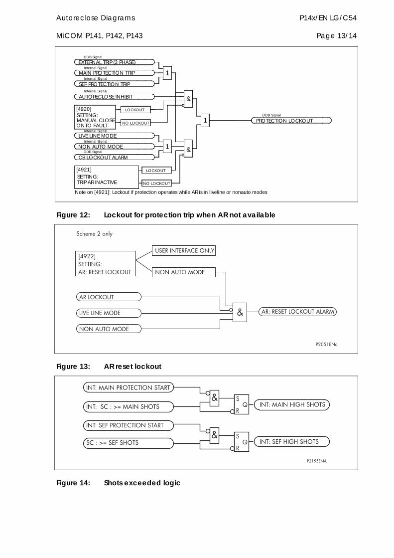
Autoreclose Diagrams P14x/EN LG/C54 MiCOM P141, P142, P143 Page 13/14
1
Note on [4921]: Lockout if protection operates while AR is in liveline or nonauto modes
[4920]SETTING:MANUAL CLOSEONTO FAULT NO LOCKOUT
[4921]SETTING:TRIP AR INACTIVE
CB LOCKOUT ALARM
LIVE LINE MODE
NON AUTO MODEInternal Signal
DDB Signal
Internal Signal
NO LOCKOUT
LOCKOUT
1 &
EXTERNAL TRIP (3 PHASE)
LOCKOUT
SEF PROTECTION TRIP
AUTORECLOSE INHIBITInternal Signal
MAIN PROTECTION TRIPInternal Signal
Internal Signal
DDB Signal
&
1
PROTECTION LOCKOUTDDB Signal
Figure 12: Lockout for protection trip when AR not available
�����������
������������������������������
�������������������
��������� �!�
����������
��"������� �!�
��������� �!�
# ����������������������
�������3
Figure 13: AR reset lockout
����� ����$���������������
����� ����%��%��%���
���������%��%��%��������&'������%���
���������$���������������
�����������&'� �����%���
�
�(
�
�(
#
#
$�)**���
Figure 14: Shots exceeded logic
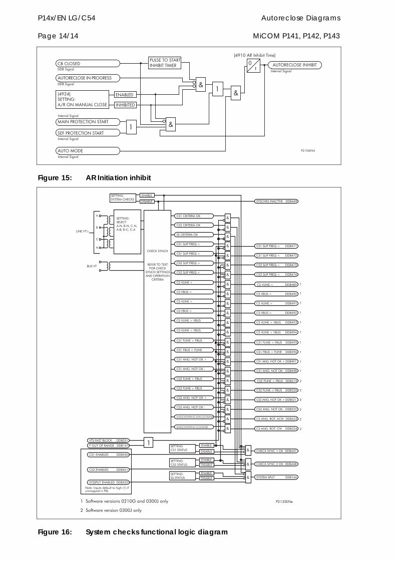
P14x/EN LG/C54 Autoreclose Diagrams Page 14/14 MiCOM P141, P142, P143
�+������! ��������������%�+��
����$���������������
����$���������������
���������������$�������
#
$�)*,���
!!+��-./�
!!+��-./�
0����1���������2����� �����������
���+��!
��%�+���!
$���������������%�+����� ��
)
34
�4�5/���-./�
#)
�4�5/���-./�
����� �!�
�4�5/���-./�
�4�5/���-./�
#
0��)3������-6-4��-��1
Figure 15: AR Initiation inhibit
�������1
��������������+
��������������+
�������������+
�����*������.�/
�����*������.�9
�����*������.�/
�����*������.�9
-
-
-
-
-
-
-
�!��+�����!
����*�
�����*�
������ '��������!��+�
������ '��*����:�;��:�;��:�;�:�;��:�;��:�
�
�
�
�
*����8�<5
����!+��������8����������
�,��8�
�����*������.�/������������
�����*������.�9������������
�����*������.�/������������
�����*������.�9������������
8���������*��+�����������
�!��+���������+��������
�!��+���������+��������
���������*��������������������
-
-
-
����*�
�����*�
������ '��������,�
����*�
�����*�
����*�
�����*�
������ '��������,�
������ '�������,�
��������*�����������������
��������*�����������������
�����*�������*����������
�)$1'��#=>$5�61?>2$�$)�4%&4�@�A�%?>#7==16�%#���*
�����������"������!��+
����!������� ��������������
��������
���,�������� ���������� �
���8*����9
���8�,��9
���8*����/
���8�,��/
-
-
-
-
���8*����9�������������������
���8�,��9���������������������
���8*����/��������������������
���8�,��/���������������������
���8*����/�8�,�- ���8*����/�8�,������������
���8*����9�8�,� - ���8*����9�8�,������������
�����*����/���,�
������,��/��*���
������ B������+�C
������ B������+�:
-
-
-
-
�����*����/���,�����������
������,��/��*�������������
������ B������+�C�������
������ B������+�:�������
�����*����/���,�
�����*����9���,�
������ B������+�C
������ B������+�:
-
-
-
-
�����*����/���,����������
�����*����9���,�����������
������ B������+�C�������
������ B������+�:�������
- ����� B����B���D��������
- ����� B����B��D����������
�� *��������� ������*��+D���
�� *��������� ��*��+D���
����)?$E(1�F1(5%)#5����� �#6�����G�)#2H
����)?$E(1�F1(5%)#�����G�)#2H
�
�
�
�
�
�
�
�
�
�
�
�
�
�
�
�
Figure 16: System checks functional logic diagram

Hardware/Software Version P14x /EN VC/C54 History and Compatibility MiCOM P141, P142, P143
HARDWARE / SOFTWARE VERSION HISTORY AND COMPATIBILITY
(Note: Includes versions released and supplied to customers only)

P14x/EN VC/C54 Hardware/Software Version History and Compatibility MiCOM P141, P142, P143
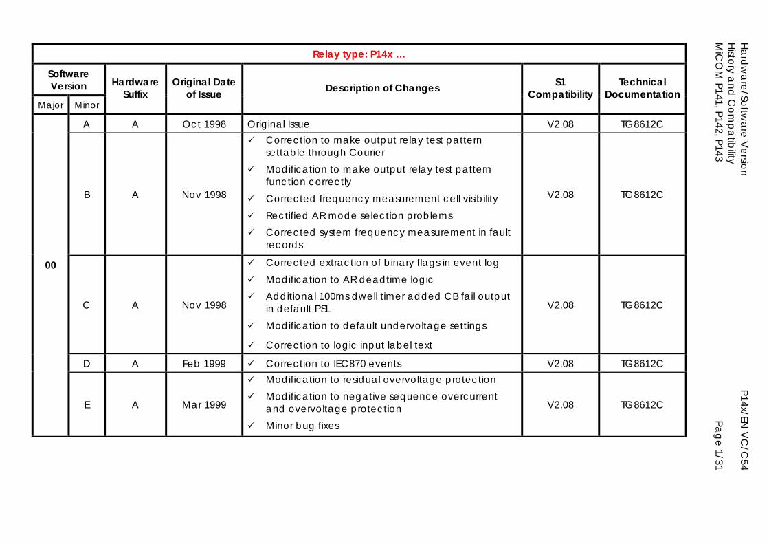
Hardw
are/Software V
ersion
P14x/EN V
C/C
54 H
istory and
Com
patibility
MiC
OM
P141, P142, P143
Page 1/31
Relay type: P14x …
Software Version
Major Minor
Hardware Suffix
Original Date of Issue Description of Changes S1
Compatibility Technical
Documentation
A A Oct 1998 Original Issue V2.08 TG8612C
B A Nov 1998
Correction to make output relay test pattern settable through Courier
Modification to make output relay test pattern function correctly
Corrected frequency measurement cell visibility Rectified AR mode selection problems Corrected system frequency measurement in fault
records
V2.08 TG8612C
00
C A Nov 1998
Corrected extraction of binary flags in event log Modification to AR deadtime logic Additional 100ms dwell timer added CB fail output
in default PSL Modification to default undervoltage settings
Correction to logic input label text
V2.08 TG8612C
D A Feb 1999 Correction to IEC870 events V2.08 TG8612C
E A Mar 1999
Modification to residual overvoltage protection Modification to negative sequence overcurrent
and overvoltage protection Minor bug fixes
V2.08 TG8612C
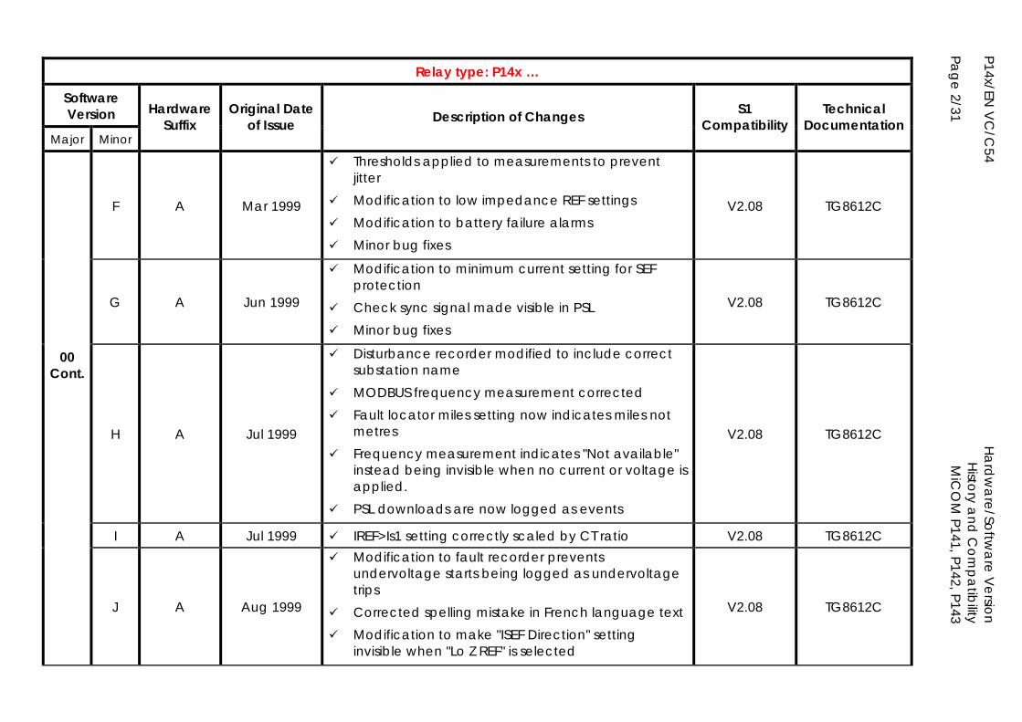
P14x/EN V
C/C
54
Ha
rdw
are/Softw
are V
ersion
H
istory and
Com
patibility
Page 2/31
M
iCO
M P141, P142, P143
Relay type: P14x …
Software Version
Major Minor
Hardware Suffix
Original Date of Issue Description of Changes S1
Compatibility Technical
Documentation
F A Mar 1999
Thresholds applied to measurements to prevent jitter
Modification to low impedance REF settings Modification to battery failure alarms Minor bug fixes
V2.08 TG8612C
G A Jun 1999
Modification to minimum current setting for SEF protection
Check sync signal made visible in PSL Minor bug fixes
V2.08 TG8612C
00 Cont.
H A Jul 1999
Disturbance recorder modified to include correct substation name
MODBUS frequency measurement corrected Fault locator miles setting now indicates miles not
metres Frequency measurement indicates "Not available"
instead being invisible when no current or voltage is applied.
PSL downloads are now logged as events
V2.08 TG8612C
I A Jul 1999 IREF>Is1 setting correctly scaled by CT ratio V2.08 TG8612C
J A Aug 1999
Modification to fault recorder prevents undervoltage starts being logged as undervoltage trips
Corrected spelling mistake in French language text Modification to make "ISEF Direction" setting
invisible when "Lo Z REF" is selected
V2.08 TG8612C
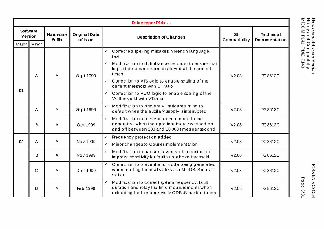
Hardw
are/Software V
ersion
P14x/EN V
C/C
54 H
istory and
Com
patibility
MiC
OM
P141, P142, P143
Page 3/31
Relay type: P14x …
Software Version
Major Minor
Hardware Suffix
Original Date of Issue Description of Changes S1
Compatibility Technical
Documentation
A A Sept 1999
Corrected spelling mistakes in French language text
Modification to disturbance recorder to ensure that logic state changes are displayed at the correct times
Correction to VTS logic to enable scaling of the current threshold with CT ratio
Correction to VCO logic to enable scaling of the V< threshold with VT ratio
V2.08 TG8612C
A A Sept 1999 Modification to prevent VT ratios returning to
default when the auxiliary supply is interrupted V2.08 TG8612C
01
B A Oct 1999 Modification to prevent an error code being
generated when the opto inputs are switched on and off between 200 and 10,000 times per second
V2.08 TG8612C
02 A A Nov 1999 Frequency protection added Minor changes to Courier implementation V2.08 TG8612C
B A Nov 1999 Modification to transient overreach algorithm to
improve sensitivity for faults just above threshold V2.08 TG8612C
C A Dec 1999
Correction to prevent error code being generated when reading thermal state via a MODBUS master station
V2.08 TG8612C
D A Feb 1999
Modification to correct system frequency, fault duration and relay trip time measurements when extracting fault records via MODBUS master station
V2.08 TG8612C
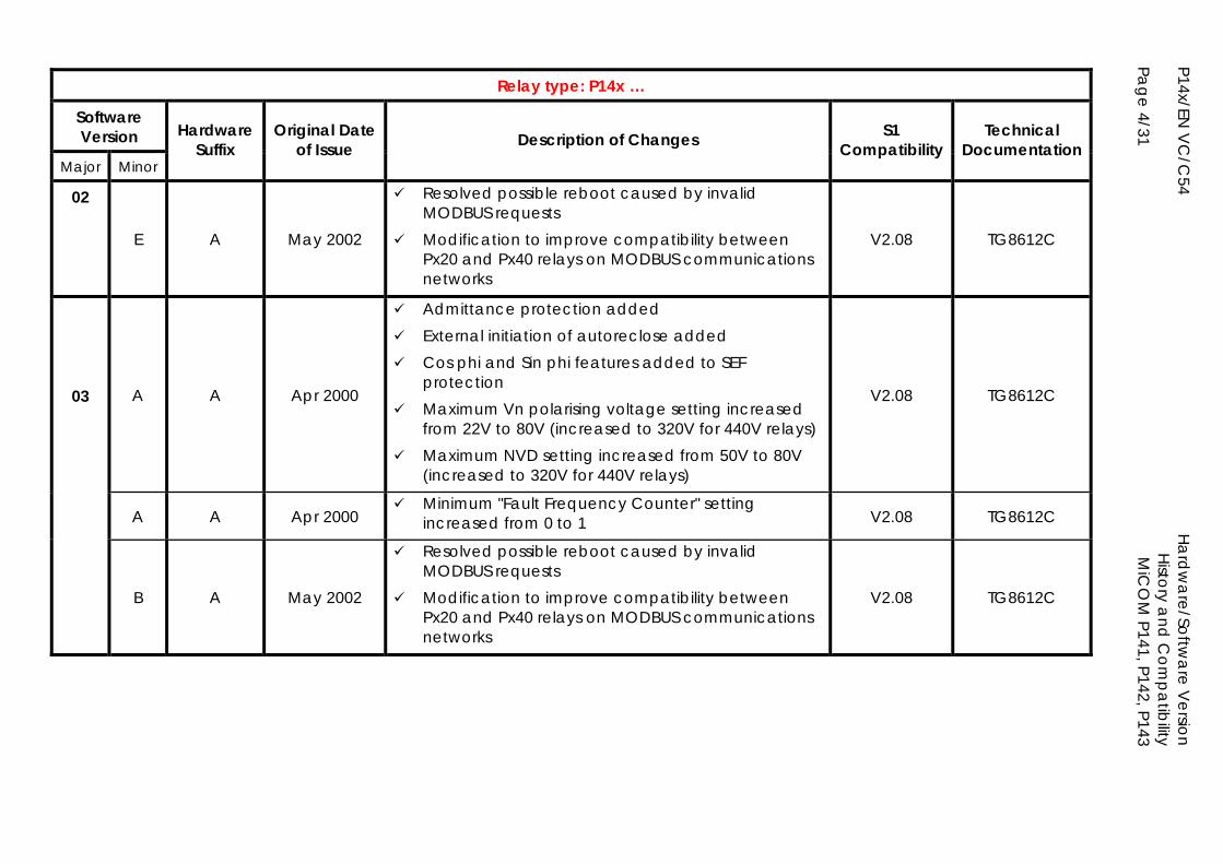
P14x/EN V
C/C
54
Ha
rdw
are/Softw
are V
ersion
H
istory and
Com
patibility
Page 4/31
M
iCO
M P141, P142, P143
Relay type: P14x …
Software Version
Major Minor
Hardware Suffix
Original Date of Issue Description of Changes S1
Compatibility Technical
Documentation
02
E A May 2002
Resolved possible reboot caused by invalid MODBUS requests
Modification to improve compatibility between Px20 and Px40 relays on MODBUS communications networks
V2.08 TG8612C
03 A A Apr 2000
Admittance protection added External initiation of autoreclose added Cos phi and Sin phi features added to SEF
protection Maximum Vn polarising voltage setting increased
from 22V to 80V (increased to 320V for 440V relays) Maximum NVD setting increased from 50V to 80V
(increased to 320V for 440V relays)
V2.08 TG8612C
A A Apr 2000 Minimum "Fault Frequency Counter" setting
increased from 0 to 1 V2.08 TG8612C
B A May 2002
Resolved possible reboot caused by invalid MODBUS requests
Modification to improve compatibility between Px20 and Px40 relays on MODBUS communications networks
V2.08 TG8612C
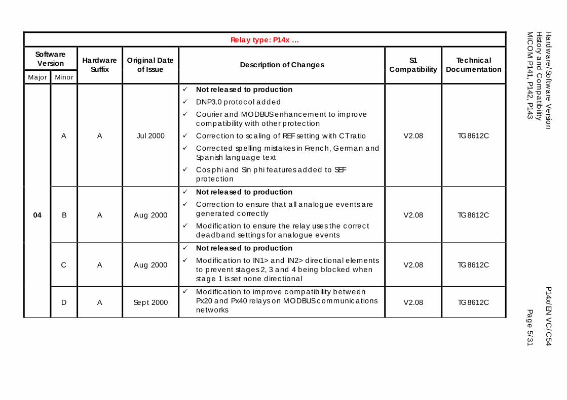
Hardw
are/Software V
ersion
P14x/EN V
C/C
54 H
istory and
Com
patibility
MiC
OM
P141, P142, P143
Page 5/31
Relay type: P14x …
Software Version
Major Minor
Hardware Suffix
Original Date of Issue Description of Changes S1
Compatibility Technical
Documentation
A A Jul 2000
Not released to production DNP3.0 protocol added Courier and MODBUS enhancement to improve
compatibility with other protection Correction to scaling of REF setting with CT ratio Corrected spelling mistakes in French, German and
Spanish language text Cos phi and Sin phi features added to SEF
protection
V2.08 TG8612C
04 B A Aug 2000
Not released to production Correction to ensure that all analogue events are
generated correctly Modification to ensure the relay uses the correct
deadband settings for analogue events
V2.08 TG8612C
C A Aug 2000
Not released to production Modification to IN1> and IN2> directional elements
to prevent stages 2, 3 and 4 being blocked when stage 1 is set none directional
V2.08 TG8612C
D A Sept 2000 Modification to improve compatibility between
Px20 and Px40 relays on MODBUS communications networks
V2.08 TG8612C
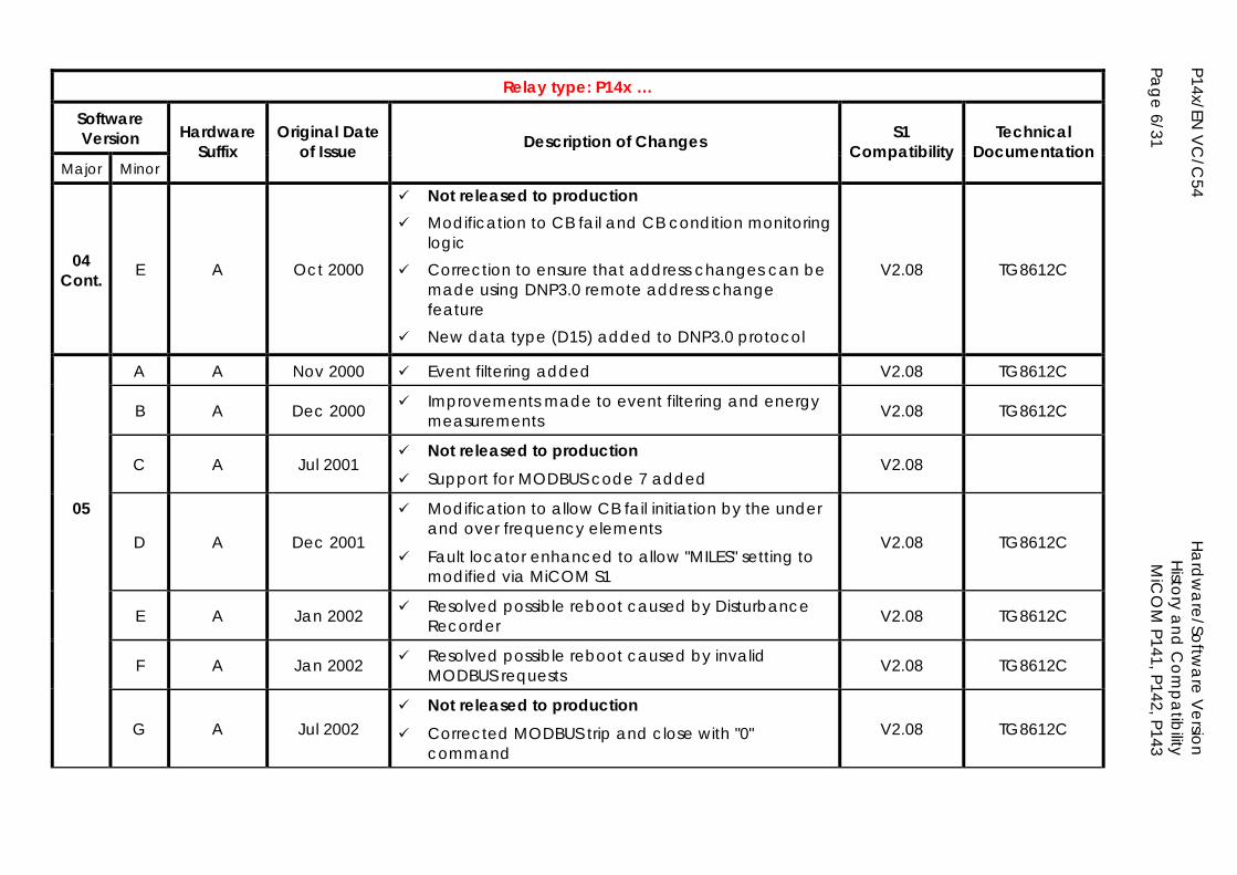
P14x/EN V
C/C
54
Ha
rdw
are/Softw
are V
ersion
H
istory and
Com
patibility
Page 6/31
M
iCO
M P141, P142, P143
Relay type: P14x …
Software Version
Major Minor
Hardware Suffix
Original Date of Issue Description of Changes S1
Compatibility Technical
Documentation
04 Cont. E A Oct 2000
Not released to production Modification to CB fail and CB condition monitoring
logic Correction to ensure that address changes can be
made using DNP3.0 remote address change feature
New data type (D15) added to DNP3.0 protocol
V2.08 TG8612C
A A Nov 2000 Event filtering added V2.08 TG8612C
B A Dec 2000 Improvements made to event filtering and energy measurements V2.08 TG8612C
C A Jul 2001 Not released to production Support for MODBUS code 7 added
V2.08
05
D A Dec 2001
Modification to allow CB fail initiation by the under and over frequency elements
Fault locator enhanced to allow "MILES" setting to modified via MiCOM S1
V2.08 TG8612C
E A Jan 2002 Resolved possible reboot caused by Disturbance Recorder V2.08 TG8612C
F A Jan 2002 Resolved possible reboot caused by invalid MODBUS requests V2.08 TG8612C
G A Jul 2002 Not released to production Corrected MODBUS trip and close with "0"
command V2.08 TG8612C
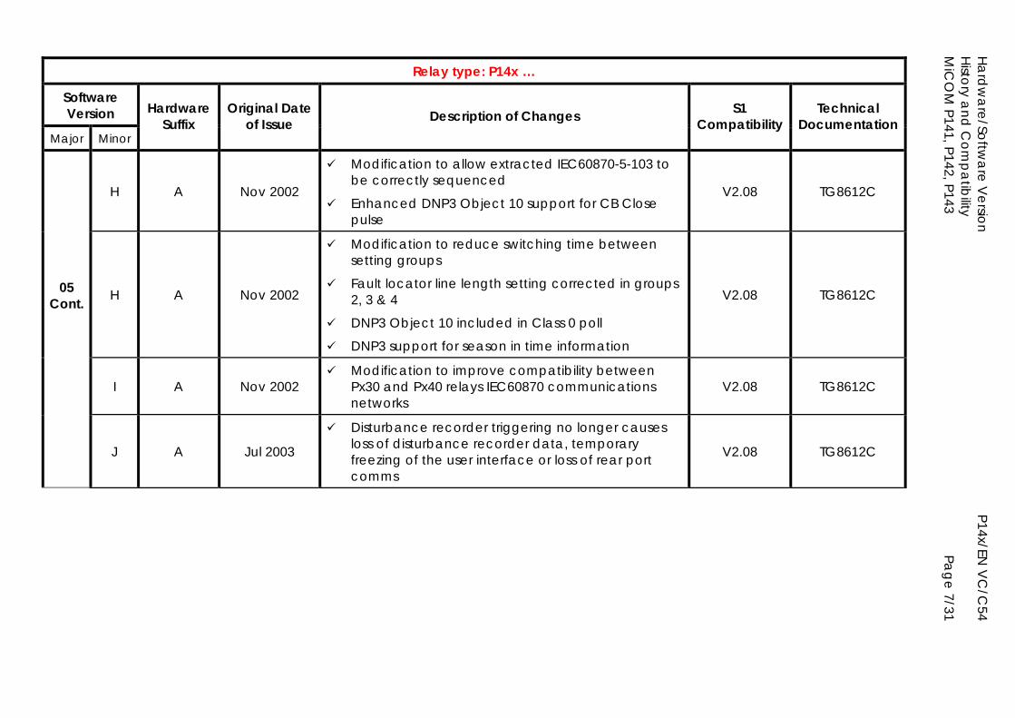
Hardw
are/Software V
ersion
P14x/EN V
C/C
54 H
istory and
Com
patibility
MiC
OM
P141, P142, P143
Page 7/31
Relay type: P14x …
Software Version
Major Minor
Hardware Suffix
Original Date of Issue Description of Changes S1
Compatibility Technical
Documentation
H A Nov 2002
Modification to allow extracted IEC60870-5-103 to be correctly sequenced
Enhanced DNP3 Object 10 support for CB Close pulse
V2.08 TG8612C
05 Cont. H A Nov 2002
Modification to reduce switching time between setting groups
Fault locator line length setting corrected in groups 2, 3 & 4
DNP3 Object 10 included in Class 0 poll
DNP3 support for season in time information
V2.08 TG8612C
I A Nov 2002 Modification to improve compatibility between
Px30 and Px40 relays IEC60870 communications networks
V2.08 TG8612C
J A Jul 2003
Disturbance recorder triggering no longer causes loss of disturbance recorder data, temporary freezing of the user interface or loss of rear port comms
V2.08 TG8612C
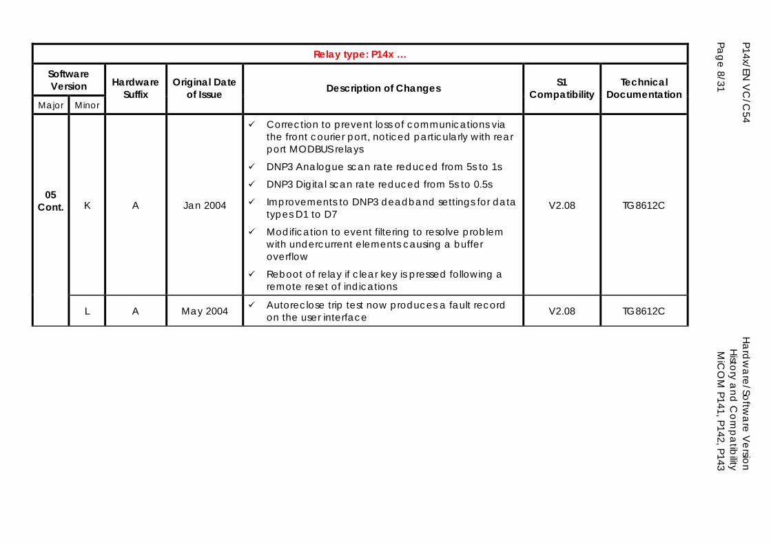
P14x/EN V
C/C
54
Ha
rdw
are/Softw
are V
ersion
H
istory and
Com
patibility
Page 8/31
M
iCO
M P141, P142, P143
Relay type: P14x …
Software Version
Major Minor
Hardware Suffix
Original Date of Issue Description of Changes S1
Compatibility Technical
Documentation
05 Cont. K A Jan 2004
Correction to prevent loss of communications via the front courier port, noticed particularly with rear port MODBUS relays
DNP3 Analogue scan rate reduced from 5s to 1s
DNP3 Digital scan rate reduced from 5s to 0.5s
Improvements to DNP3 deadband settings for data types D1 to D7
Modification to event filtering to resolve problem with undercurrent elements causing a buffer overflow
Reboot of relay if clear key is pressed following a remote reset of indications
V2.08 TG8612C
L A May 2004 Autoreclose trip test now produces a fault record on the user interface V2.08 TG8612C
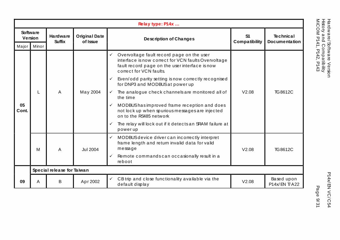
Hardw
are/Software V
ersion
P14x/EN V
C/C
54 H
istory and
Com
patibility
MiC
OM
P141, P142, P143
Page 9/31
Relay type: P14x …
Software Version
Major Minor
Hardware Suffix
Original Date of Issue Description of Changes S1
Compatibility Technical
Documentation
L A May 2004
Overvoltage fault record page on the user interface is now correct for VCN faults Overvoltage fault record page on the user interface is now correct for VCN faults.
Even/odd parity setting is now correctly recognised for DNP3 and MODBUS at power up
The analogue check channels are monitored all of the time
MODBUS has improved frame reception and does not lock up when spurious messages are injected on to the RS485 network
The relay will lock out if it detects an SRAM failure at power up
V2.08 TG8612C
05 Cont.
M A Jul 2004
MODBUS device driver can incorrectly interpret frame length and return invalid data for valid message
Remote commands can occasionally result in a reboot
V2.08 TG8612C
Special release for Taiwan
09 A B Apr 2002 CB trip and close functionality available via the default display V2.08 Based upon
P14x/EN T/A22
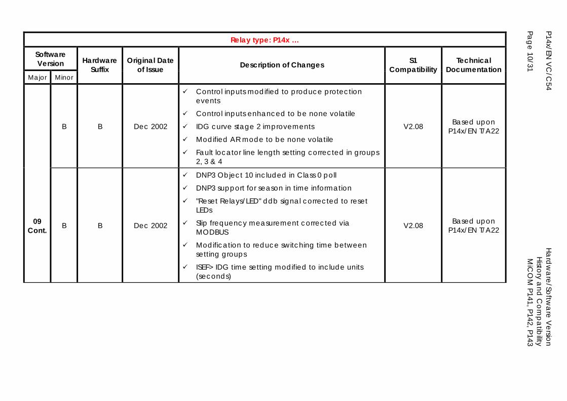
P14x/EN V
C/C
54
Ha
rdw
are/Softw
are V
ersion
H
istory and
Com
patibility
Page 10/31
MiC
OM
P141, P142, P143
Relay type: P14x …
Software Version
Major Minor
Hardware Suffix
Original Date of Issue Description of Changes S1
Compatibility Technical
Documentation
B B Dec 2002
Control inputs modified to produce protection events
Control inputs enhanced to be none volatile
IDG curve stage 2 improvements
Modified AR mode to be none volatile
Fault locator line length setting corrected in groups 2, 3 & 4
V2.08 Based upon P14x/EN T/A22
09 Cont. B B Dec 2002
DNP3 Object 10 included in Class 0 poll
DNP3 support for season in time information
"Reset Relays/LED" ddb signal corrected to reset LEDs
Slip frequency measurement corrected via MODBUS
Modification to reduce switching time between setting groups
ISEF> IDG time setting modified to include units (seconds)
V2.08 Based upon P14x/EN T/A22
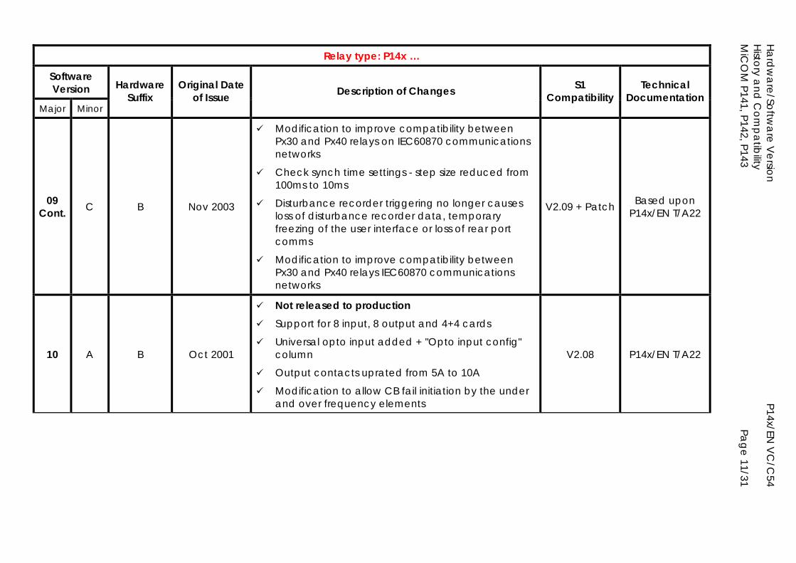
Hardw
are/Software V
ersion
P14x/EN V
C/C
54 H
istory and
Com
patibility
MiC
OM
P141, P142, P143
Page 11/31
Relay type: P14x …
Software Version
Major Minor
Hardware Suffix
Original Date of Issue Description of Changes S1
Compatibility Technical
Documentation
09 Cont. C B Nov 2003
Modification to improve compatibility between Px30 and Px40 relays on IEC60870 communications networks
Check synch time settings - step size reduced from 100ms to 10ms
Disturbance recorder triggering no longer causes loss of disturbance recorder data, temporary freezing of the user interface or loss of rear port comms
Modification to improve compatibility between Px30 and Px40 relays IEC60870 communications networks
V2.09 + Patch Based upon P14x/EN T/A22
10 A B Oct 2001
Not released to production Support for 8 input, 8 output and 4+4 cards
Universal opto input added + "Opto input config" column
Output contacts uprated from 5A to 10A
Modification to allow CB fail initiation by the under and over frequency elements
V2.08 P14x/EN T/A22
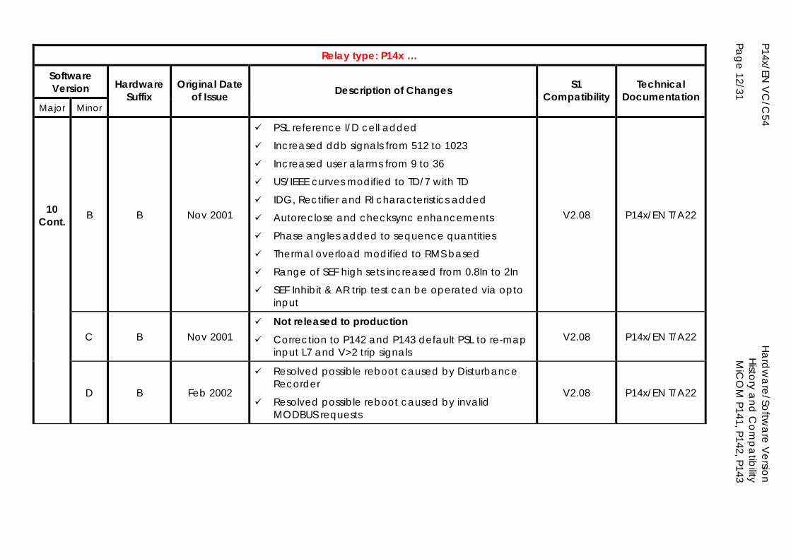
P14x/EN V
C/C
54
Ha
rdw
are/Softw
are V
ersion
H
istory and
Com
patibility
Page 12/31
MiC
OM
P141, P142, P143
Relay type: P14x …
Software Version
Major Minor
Hardware Suffix
Original Date of Issue Description of Changes S1
Compatibility Technical
Documentation
10 Cont. B B Nov 2001
PSL reference I/D cell added
Increased ddb signals from 512 to 1023
Increased user alarms from 9 to 36
US/IEEE curves modified to TD/7 with TD
IDG, Rectifier and RI characteristics added
Autoreclose and checksync enhancements
Phase angles added to sequence quantities
Thermal overload modified to RMS based
Range of SEF high sets increased from 0.8In to 2In
SEF Inhibit & AR trip test can be operated via opto input
V2.08 P14x/EN T/A22
C B Nov 2001 Not released to production Correction to P142 and P143 default PSL to re-map
input L7 and V>2 trip signals V2.08 P14x/EN T/A22
D B Feb 2002
Resolved possible reboot caused by Disturbance Recorder
Resolved possible reboot caused by invalid MODBUS requests
V2.08 P14x/EN T/A22
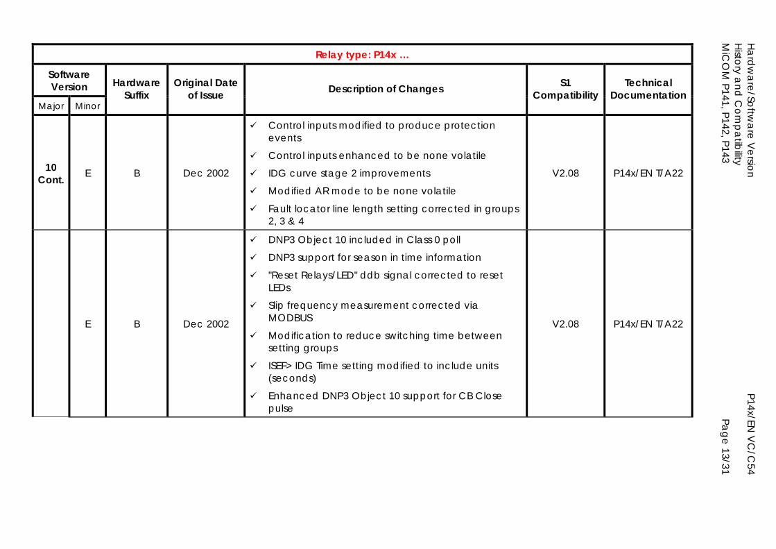
Hardw
are/Software V
ersion
P14x/EN V
C/C
54 H
istory and
Com
patibility
MiC
OM
P141, P142, P143
Page 13/31
Relay type: P14x …
Software Version
Major Minor
Hardware Suffix
Original Date of Issue Description of Changes S1
Compatibility Technical
Documentation
10 Cont. E B Dec 2002
Control inputs modified to produce protection events
Control inputs enhanced to be none volatile
IDG curve stage 2 improvements
Modified AR mode to be none volatile
Fault locator line length setting corrected in groups 2, 3 & 4
V2.08 P14x/EN T/A22
E B Dec 2002
DNP3 Object 10 included in Class 0 poll
DNP3 support for season in time information
"Reset Relays/LED" ddb signal corrected to reset LEDs
Slip frequency measurement corrected via MODBUS
Modification to reduce switching time between setting groups
ISEF> IDG Time setting modified to include units (seconds)
Enhanced DNP3 Object 10 support for CB Close pulse
V2.08 P14x/EN T/A22
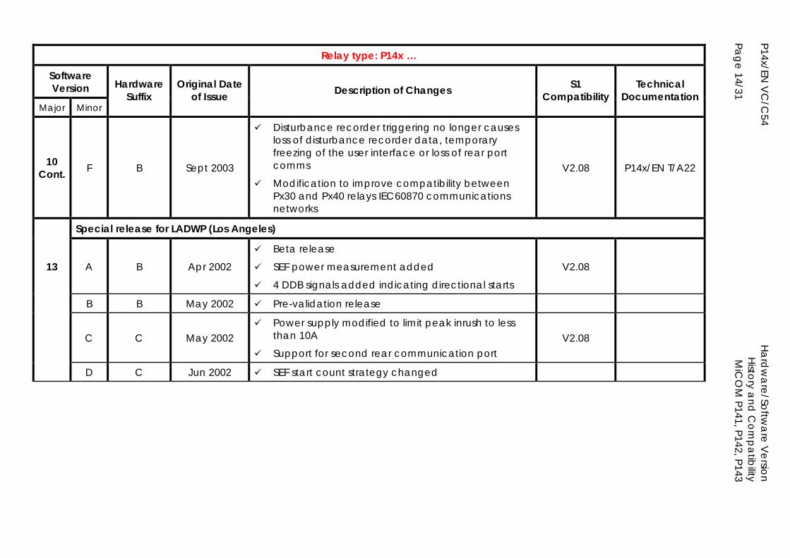
P14x/EN V
C/C
54
Ha
rdw
are/Softw
are V
ersion
H
istory and
Com
patibility
Page 14/31
MiC
OM
P141, P142, P143
Relay type: P14x …
Software Version
Major Minor
Hardware Suffix
Original Date of Issue Description of Changes S1
Compatibility Technical
Documentation
10 Cont. F B Sept 2003
Disturbance recorder triggering no longer causes loss of disturbance recorder data, temporary freezing of the user interface or loss of rear port comms
Modification to improve compatibility between Px30 and Px40 relays IEC60870 communications networks
V2.08 P14x/EN T/A22
Special release for LADWP (Los Angeles)
13 A B Apr 2002
Beta release
SEF power measurement added
4 DDB signals added indicating directional starts
V2.08
B B May 2002 Pre-validation release
C C May 2002 Power supply modified to limit peak inrush to less
than 10A
Support for second rear communication port V2.08
D C Jun 2002 SEF start count strategy changed
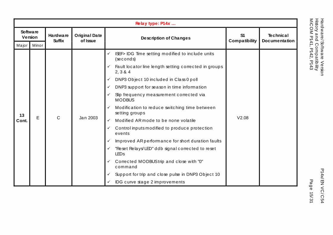
Hardw
are/Software V
ersion
P14x/EN V
C/C
54 H
istory and
Com
patibility
MiC
OM
P141, P142, P143
Page 15/31
Relay type: P14x …
Software Version
Major Minor
Hardware Suffix
Original Date of Issue Description of Changes S1
Compatibility Technical
Documentation
13 Cont. E C Jan 2003
ISEF> IDG Time setting modified to include units (seconds)
Fault locator line length setting corrected in groups 2, 3 & 4
DNP3 Object 10 included in Class 0 poll
DNP3 support for season in time information
Slip frequency measurement corrected via MODBUS
Modification to reduce switching time between setting groups
Modified AR mode to be none volatile
Control inputs modified to produce protection events
Improved AR performance for short duration faults
"Reset Relays/LED" ddb signal corrected to reset LEDs
Corrected MODBUS trip and close with "0" command
Support for trip and close pulse in DNP3 Object 10
IDG curve stage 2 improvements
V2.08
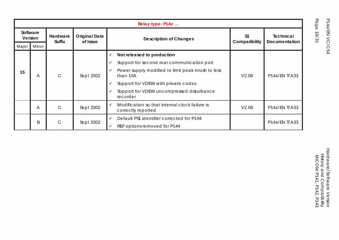
P14x/EN V
C/C
54
Ha
rdw
are/Softw
are V
ersion
H
istory and
Com
patibility
Page 16/31
MiC
OM
P141, P142, P143
Relay type: P14x …
Software Version
Major Minor
Hardware Suffix
Original Date of Issue Description of Changes S1
Compatibility Technical
Documentation
15
A C Sept 2002
Not released to production Support for second rear communication port
Power supply modified to limit peak inrush to less than 10A
Support for VDEW with private codes
Support for VDEW uncompressed disturbance recorder
V2.08 P14x/EN T/A33
A C Sept 2002 Modification so that internal clock failure is correctly reported V2.08 P14x/EN T/A33
B C Sept 2002 Default PSL identifier corrected for P144
REF options removed for P144 P14x/EN T/A33
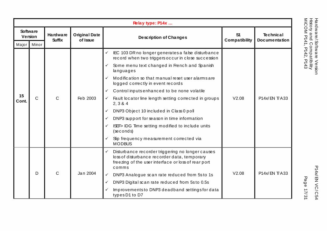
Hardw
are/Software V
ersion
P14x/EN V
C/C
54 H
istory and
Com
patibility
MiC
OM
P141, P142, P143
Page 17/31
Relay type: P14x …
Software Version
Major Minor
Hardware Suffix
Original Date of Issue Description of Changes S1
Compatibility Technical
Documentation
15 Cont. C C Feb 2003
IEC 103 DR no longer generates a false disturbance record when two triggers occur in close succession
Some menu text changed in French and Spanish languages
Modification so that manual reset user alarms are logged correctly in event records
Control inputs enhanced to be none volatile
Fault locator line length setting corrected in groups 2, 3 & 4
DNP3 Object 10 included in Class 0 poll
DNP3 support for season in time information
ISEF> IDG Time setting modified to include units (seconds)
Slip frequency measurement corrected via MODBUS
V2.08 P14x/EN T/A33
D C Jan 2004
Disturbance recorder triggering no longer causes loss of disturbance recorder data, temporary freezing of the user interface or loss of rear port comms
DNP3 Analogue scan rate reduced from 5s to 1s
DNP3 Digital scan rate reduced from 5s to 0.5s
Improvements to DNP3 deadband settings for data types D1 to D7
V2.08 P14x/EN T/A33
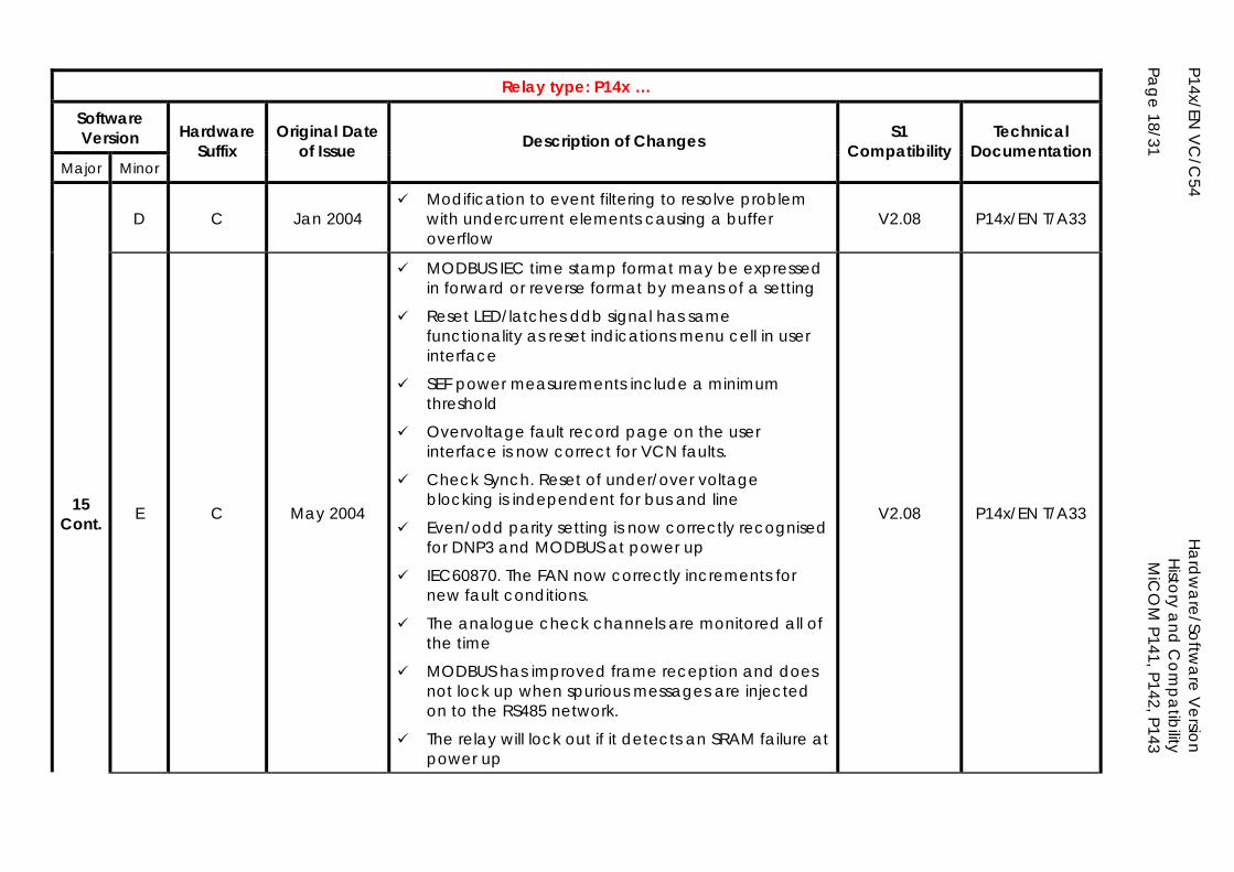
P14x/EN V
C/C
54
Ha
rdw
are/Softw
are V
ersion
H
istory and
Com
patibility
Page 18/31
MiC
OM
P141, P142, P143
Relay type: P14x …
Software Version
Major Minor
Hardware Suffix
Original Date of Issue Description of Changes S1
Compatibility Technical
Documentation
D C Jan 2004 Modification to event filtering to resolve problem
with undercurrent elements causing a buffer overflow
V2.08 P14x/EN T/A33
15 Cont. E C May 2004
MODBUS IEC time stamp format may be expressed in forward or reverse format by means of a setting
Reset LED/latches ddb signal has same functionality as reset indications menu cell in user interface
SEF power measurements include a minimum threshold
Overvoltage fault record page on the user interface is now correct for VCN faults.
Check Synch. Reset of under/over voltage blocking is independent for bus and line
Even/odd parity setting is now correctly recognised for DNP3 and MODBUS at power up
IEC60870. The FAN now correctly increments for new fault conditions.
The analogue check channels are monitored all of the time
MODBUS has improved frame reception and does not lock up when spurious messages are injected on to the RS485 network.
The relay will lock out if it detects an SRAM failure at power up
V2.08 P14x/EN T/A33
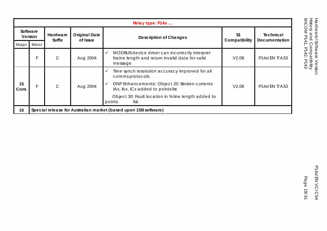
Hardw
are/Software V
ersion
P14x/EN V
C/C
54 H
istory and
Com
patibility
MiC
OM
P141, P142, P143
Page 19/31
Relay type: P14x …
Software Version
Major Minor
Hardware Suffix
Original Date of Issue Description of Changes S1
Compatibility Technical
Documentation
F C Aug 2004 MODBUS device driver can incorrectly interpret
frame length and return invalid data for valid message
V2.08 P14x/EN T/A33
15 Cont. F C Aug 2004
Time synch resolution accuracy improved for all comms protocols.
DNP Enhancements:: Object 20: Broken currents IAx, Ibx, ICx added to points list
Object 30: Fault location in % line length added to points list.
V2.08 P14x/EN T/A33
16 Special release for Australian market (based upon 15B software)
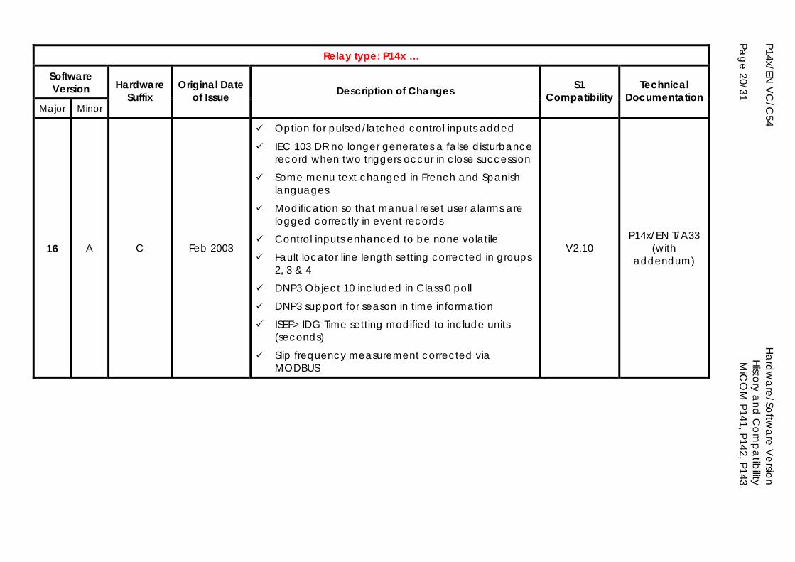
P14x/EN V
C/C
54
Ha
rdw
are/Softw
are V
ersion
H
istory and
Com
patibility
Page 20/31
MiC
OM
P141, P142, P143
Relay type: P14x …
Software Version
Major Minor
Hardware Suffix
Original Date of Issue Description of Changes S1
Compatibility Technical
Documentation
16 A C Feb 2003
Option for pulsed/latched control inputs added
IEC 103 DR no longer generates a false disturbance record when two triggers occur in close succession
Some menu text changed in French and Spanish languages
Modification so that manual reset user alarms are logged correctly in event records
Control inputs enhanced to be none volatile
Fault locator line length setting corrected in groups 2, 3 & 4
DNP3 Object 10 included in Class 0 poll
DNP3 support for season in time information
ISEF> IDG Time setting modified to include units (seconds)
Slip frequency measurement corrected via MODBUS
V2.10 P14x/EN T/A33
(with addendum)
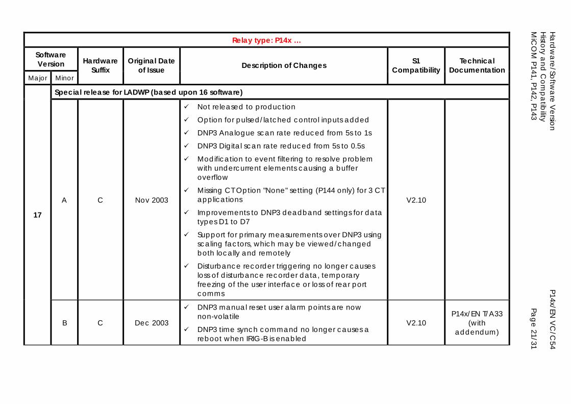
Hardw
are/Software V
ersion
P14x/EN V
C/C
54 H
istory and
Com
patibility
MiC
OM
P141, P142, P143
Page 21/31
Relay type: P14x …
Software Version
Major Minor
Hardware Suffix
Original Date of Issue Description of Changes S1
Compatibility Technical
Documentation
Special release for LADWP (based upon 16 software)
A C Nov 2003
Not released to production
Option for pulsed/latched control inputs added
DNP3 Analogue scan rate reduced from 5s to 1s
DNP3 Digital scan rate reduced from 5s to 0.5s
Modification to event filtering to resolve problem with undercurrent elements causing a buffer overflow
Missing CT Option "None" setting (P144 only) for 3 CT applications
Improvements to DNP3 deadband settings for data types D1 to D7
Support for primary measurements over DNP3 using scaling factors, which may be viewed/changed both locally and remotely
Disturbance recorder triggering no longer causes loss of disturbance recorder data, temporary freezing of the user interface or loss of rear port comms
V2.10
17
B C Dec 2003
DNP3 manual reset user alarm points are now non-volatile
DNP3 time synch command no longer causes a reboot when IRIG-B is enabled
V2.10 P14x/EN T/A33
(with addendum)
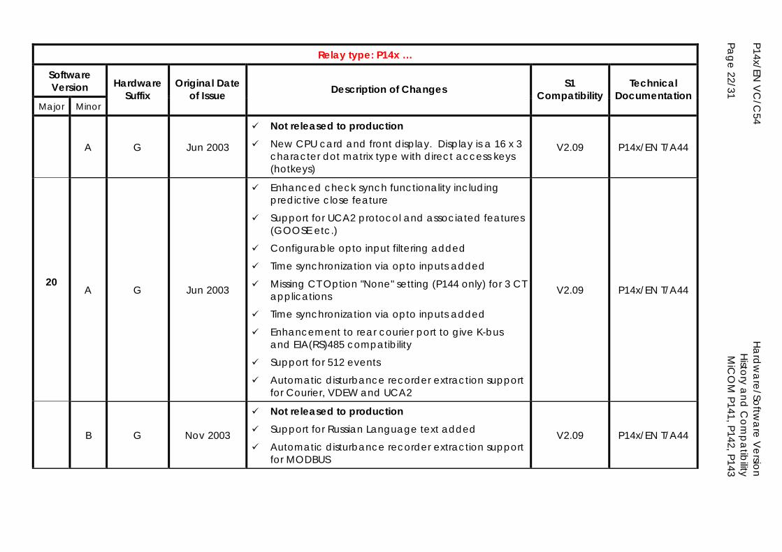
P14x/EN V
C/C
54
Ha
rdw
are/Softw
are V
ersion
H
istory and
Com
patibility
Page 22/31
MiC
OM
P141, P142, P143
Relay type: P14x …
Software Version
Major Minor
Hardware Suffix
Original Date of Issue Description of Changes S1
Compatibility Technical
Documentation
A G Jun 2003
Not released to production New CPU card and front display. Display is a 16 x 3
character dot matrix type with direct access keys (hotkeys)
V2.09 P14x/EN T/A44
20
A G Jun 2003
Enhanced check synch functionality including predictive close feature
Support for UCA2 protocol and associated features (GOOSE etc.)
Configurable opto input filtering added
Time synchronization via opto inputs added
Missing CT Option "None" setting (P144 only) for 3 CT applications
Time synchronization via opto inputs added
Enhancement to rear courier port to give K-bus and EIA(RS)485 compatibility
Support for 512 events
Automatic disturbance recorder extraction support for Courier, VDEW and UCA2
V2.09 P14x/EN T/A44
B G Nov 2003
Not released to production
Support for Russian Language text added
Automatic disturbance recorder extraction support for MODBUS
V2.09 P14x/EN T/A44
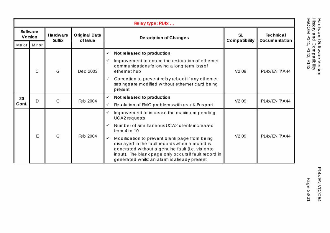
Hardw
are/Software V
ersion
P14x/EN V
C/C
54 H
istory and
Com
patibility
MiC
OM
P141, P142, P143
Page 23/31
Relay type: P14x …
Software Version
Major Minor
Hardware Suffix
Original Date of Issue Description of Changes S1
Compatibility Technical
Documentation
C G Dec 2003
Not released to production Improvement to ensure the restoration of ethernet
communications following a long term loss of ethernet hub
Correction to prevent relay reboot if any ethernet settings are modified without ethernet card being present
V2.09 P14x/EN T/A44
20 Cont. D G Feb 2004
Not released to production Resolution of EMC problems with rear K-Bus port
V2.09 P14x/EN T/A44
E G Feb 2004
Improvement to increase the maximum pending UCA2 requests
Number of simultaneous UCA2 clients increased from 4 to 10
Modification to prevent blank page from being displayed in the fault records when a record is generated without a genuine fault (i.e. via opto input). The blank page only occurs if fault record in generated whilst an alarm is already present
V2.09 P14x/EN T/A44
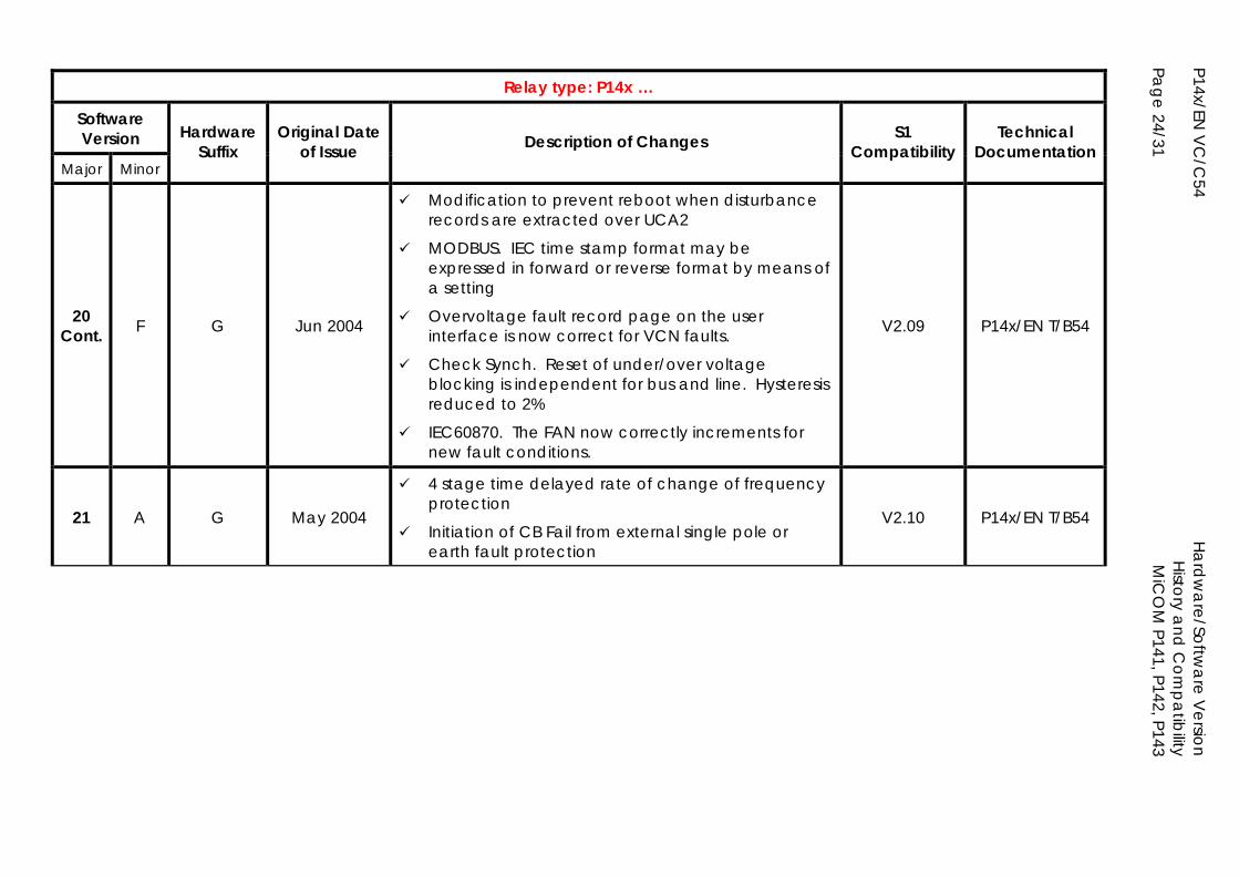
P14x/EN V
C/C
54
Ha
rdw
are/Softw
are V
ersion
H
istory and
Com
patibility
Page 24/31
MiC
OM
P141, P142, P143
Relay type: P14x …
Software Version
Major Minor
Hardware Suffix
Original Date of Issue Description of Changes S1
Compatibility Technical
Documentation
20 Cont. F G Jun 2004
Modification to prevent reboot when disturbance records are extracted over UCA2
MODBUS. IEC time stamp format may be expressed in forward or reverse format by means of a setting
Overvoltage fault record page on the user interface is now correct for VCN faults.
Check Synch. Reset of under/over voltage blocking is independent for bus and line. Hysteresis reduced to 2%
IEC60870. The FAN now correctly increments for new fault conditions.
V2.09 P14x/EN T/B54
21 A G May 2004
4 stage time delayed rate of change of frequency protection
Initiation of CB Fail from external single pole or earth fault protection
V2.10 P14x/EN T/B54
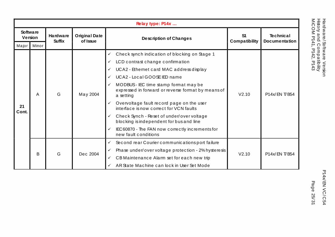
Hardw
are/Software V
ersion
P14x/EN V
C/C
54 H
istory and
Com
patibility
MiC
OM
P141, P142, P143
Page 25/31
Relay type: P14x …
Software Version
Major Minor
Hardware Suffix
Original Date of Issue Description of Changes S1
Compatibility Technical
Documentation
A G May 2004
Check synch indication of blocking on Stage 1
LCD contrast change confirmation
UCA2 - Ethernet card MAC address display
UCA2 - Local GOOSE IED name
MODBUS - IEC time stamp format may be expressed in forward or reverse format by means of a setting
Overvoltage fault record page on the user interface is now correct for VCN faults
Check Synch - Reset of under/over voltage blocking is independent for bus and line
IEC60870 - The FAN now correctly increments for new fault conditions
V2.10 P14x/EN T/B54
21 Cont.
B G Dec 2004
Second rear Courier communications port failure
Phase under/over voltage protection - 2% hysteresis
CB Maintenance Alarm set for each new trip
AR State Machine can lock in User Set Mode
V2.10 P14x/EN T/B54
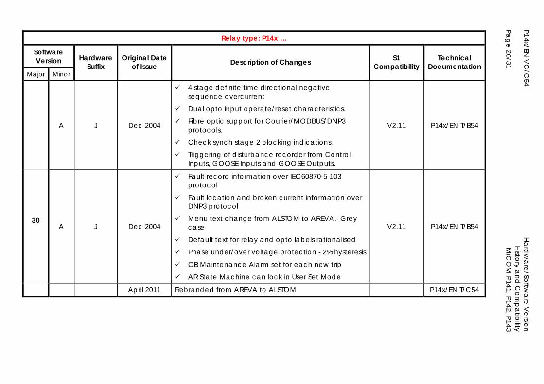
P14x/EN V
C/C
54
Ha
rdw
are/Softw
are V
ersion
H
istory and
Com
patibility
Page 26/31
MiC
OM
P141, P142, P143
Relay type: P14x …
Software Version
Major Minor
Hardware Suffix
Original Date of Issue Description of Changes S1
Compatibility Technical
Documentation
A J Dec 2004
4 stage definite time directional negative sequence overcurrent
Dual opto input operate/reset characteristics.
Fibre optic support for Courier/MODBUS/DNP3 protocols.
Check synch stage 2 blocking indications.
Triggering of disturbance recorder from Control Inputs, GOOSE Inputs and GOOSE Outputs.
V2.11 P14x/EN T/B54
30
A J Dec 2004
Fault record information over IEC60870-5-103 protocol
Fault location and broken current information over DNP3 protocol
Menu text change from ALSTOM to AREVA. Grey case
Default text for relay and opto labels rationalised
Phase under/over voltage protection - 2% hysteresis
CB Maintenance Alarm set for each new trip
AR State Machine can lock in User Set Mode
V2.11 P14x/EN T/B54
April 2011 Rebranded from AREVA to ALSTOM P14x/EN T/C54
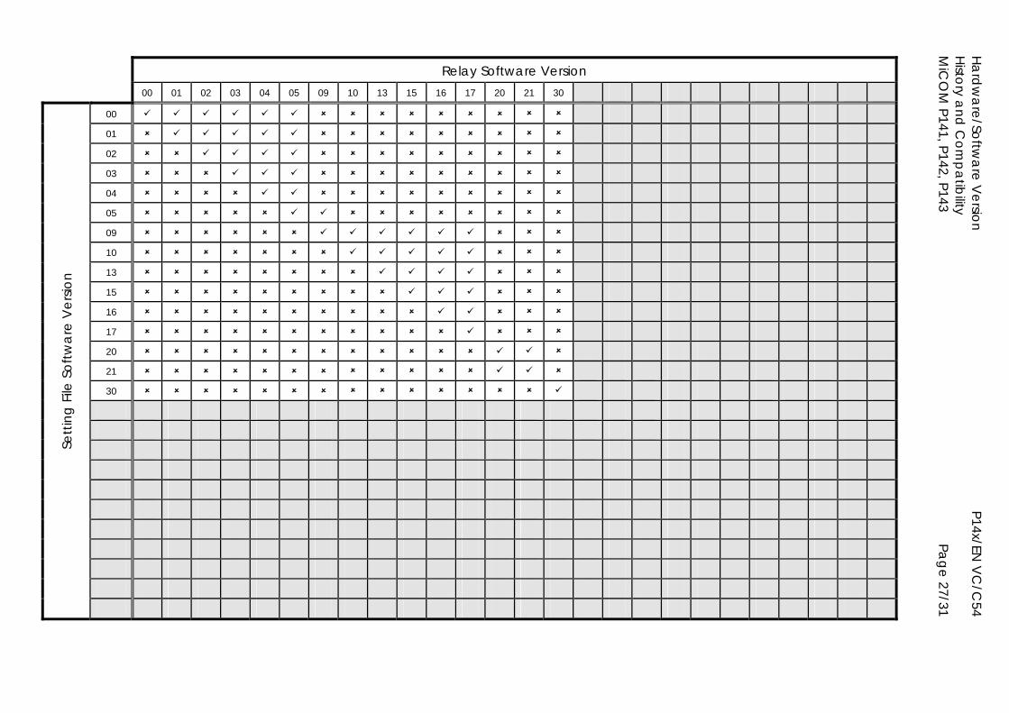
Hardw
are/Software V
ersion
P14x/EN V
C/C
54 H
istory and
Com
patibility
MiC
OM
P141, P142, P143
Page 27/31
Relay Software Version 00 01 02 03 04 05 09 10 13 15 16 17 20 21 30
00
01
02
03
04
05
09
10
13
15
16
17
20
21
30
Setti
ng F
ile S
oftw
are
Ver
sion
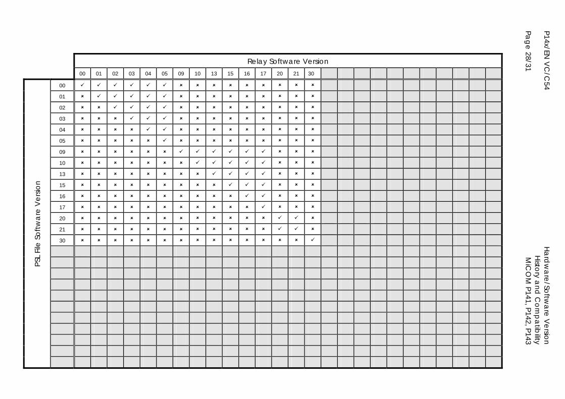
P14x/EN V
C/C
54
Ha
rdw
are/Softw
are V
ersion
H
istory and
Com
patibility
Page 28/31
MiC
OM
P141, P142, P143
Relay Software Version 00 01 02 03 04 05 09 10 13 15 16 17 20 21 30
00
01
02
03
04
05
09
10
13
15
16
17
20
21
30
PSL
File
Sof
twa
re V
ersio
n
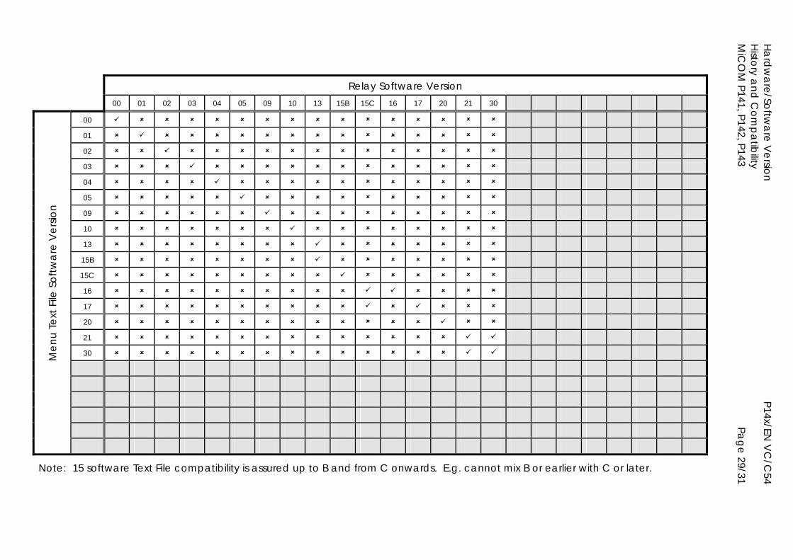
Hardw
are/Software V
ersion
P14x/EN V
C/C
54 H
istory and
Com
patibility
MiC
OM
P141, P142, P143
Page 29/31
Relay Software Version 00 01 02 03 04 05 09 10 13 15B 15C 16 17 20 21 30
00
01
02
03
04
05
09
10
13
15B
15C
16
17
20
21
30
Men
u Te
xt F
ile S
oftw
are
Ver
sion
Note: 15 software Text File compatibility is assured up to B and from C onwards. E.g. cannot mix B or earlier with C or later.
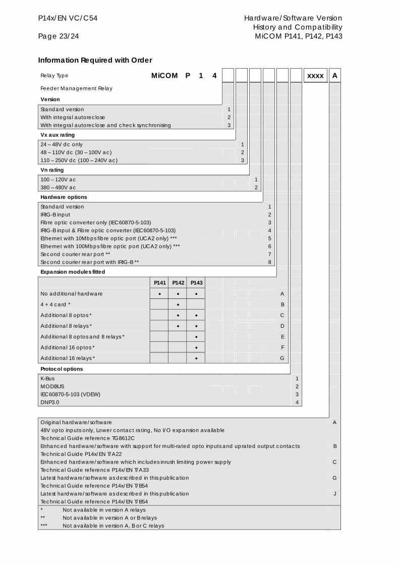
P14x/EN VC/C54 Hardware/Software Version History and Compatibility Page 23/24 MiCOM P141, P142, P143 Information Required with Order
Relay Type MiCOM P 1 4 xxxx A Feeder Management Relay
Version
Standard version With integral autoreclose With integral autoreclose and check synchronising
1 2 3
Vx aux rating
24 – 48V dc only 48 – 110V dc (30 – 100V ac) 110 – 250V dc (100 – 240V ac)
1 2 3
Vn rating
100 – 120V ac 380 – 480V ac
1 2
Hardware options
Standard version IRIG-B input Fibre optic converter only (IEC60870-5-103) IRIG-B input & Fibre optic converter (IEC60870-5-103) Ethernet with 10Mbps fibre optic port (UCA2 only) *** Ethernet with 100Mbps fibre optic port (UCA2 only) *** Second courier rear port ** Second courier rear port with IRIG-B **
1 2 3 4 5 6 7 8
Expansion modules fitted
P141 P142 P143
No additional hardware A
4 + 4 card * B
Additional 8 optos * C
Additional 8 relays * D
Additional 8 optos and 8 relays * E
Additional 16 optos * F
Additional 16 relays * G
Protocol options
K-Bus MODBUS IEC60870-5-103 (VDEW) DNP3.0
1 2 3 4
Original hardware/software 48V opto inputs only, Lower contact rating, No I/O expansion available Technical Guide reference TG8612C
A
Enhanced hardware/software with support for multi-rated opto inputs and uprated output contacts Technical Guide P14x/EN T/A22
B
Enhanced hardware/software which includes inrush limiting power supply Technical Guide reference P14x/EN T/A33
C
Latest hardware/software as described in this publication Technical Guide reference P14x/EN T/B54
G
Latest hardware/software as described in this publication Technical Guide reference P14x/EN T/B54
J
* Not available in version A relays ** Not available in version A or B relays *** Not available in version A, B or C relays

Hardware/Software Version P14x /EN VC/C54 History and Compatibility MiCOM P141, P142, P143 Page 24/24

PXXX Product Description
GRID
Alstom Grid
© - ALSTOM 2011. ALSTOM, the ALSTOM logo and any alternative version thereof are trademarks and service marks of ALSTOM. The other names mentioned, registered or not, are the property of their respective companies. The technical and other data contained in this document is provided for information only. Neither ALSTOM, its officers or employees accept responsibility for, or should be taken as making any representation or warranty (whether express or implied), as to the accuracy or completeness of such data or the achievement of any projected performance criteria where these are indicated. ALSTOM reserves the right to revise or change this data at any time without further notice.
Alstom Grid Worldwide Contact Centre
www.alstom.com/grid/contactcentre/
Tel: +44 (0) 1785 250 070
www.alstom.com

![MiCOM P14 x - electroautomatica.ruelectroautomatica.ru/img/documentation/MiCOM_P14x_LS.pdf · [ТЕРМИНАЛ РЗА] micom p14x 2 ansi iec 61850 Свойства p141 p142 p143](https://img.pdfslide.net/doc/110x75/5a788bc67f8b9a852c8c515d/micom-p14-x-micom-p14x-2-ansi-iec-61850-.jpg)


![Horváth Ignác kézzel írt jegyzete [1868] [p141]](https://img.pdfslide.net/doc/110x75/55cf91cb550346f57b90c156/horvath-ignac-kezzel-irt-jegyzete-1868-p141.jpg)
