Embed Size (px)
Citation preview
Micro- and Nano- Engineering Cellular Patterns with Plasma Technologies
by
Angela R. Dixon
A dissertation submitted in partial fulfillment of the requirements for the degree of
Doctor of Philosophy (Biomedical Engineering)
in The University of Michigan 2010
Doctoral Committee: Associate Professer Shuichi Takayama, Co-Chair Professor Katharine F. Barald, Co-Chair Professer Paul H. Krebsbach Professor Peter X. Ma Associate Professor Jan P. Stegemann

© Angela R. Dixon
2010

To my dear parents, who are my chief cheerleaders, encouraging me daily to seize all the
opportunities that were inaccessible to or overlooked by them, and to lend a hand to as many
people along the way while doing so.
ii
Acknowledgements
As my graduate student tenure comes to a close, I am obliged to acknowledge the
many persons who have assisted me in the development of this dissertation.
I remember the first encounter that I had with my research adviser, Dr. Shuichi
Takayama, to discuss what specific research interests we shared. I marveled at the
myriad of projects that were ongoing in his lab, as they each required efforts from a
unique blend of engineering and science disciplines. As time passed, I began to realize
that we both hold a desire to pursue diverse research ideas, and he has helped me to
continually refine and align my research endeavors towards a unifying and achievable
goal.
At the time I was taking a scientific communications course, of which Dr. Kate
Barald was my faculty adviser, I did not suspect that, in addition to curriculum
knowledge, I would gain another long term researcher adviser. I am grateful to her for
willingly sharing her laboratory resources with me, as well as providing extensive
critiques to my written documents. Also, I must add that she has a unique ability to
respond to neuroscience related questions with intriguing, didactic, and pleasant
narrations.
I would also like to thank my other committee members, Dr. Krebsbach, Dr. Ma,
and Dr. Stegemann for agreeing to serve on my committee. I admire all my committee
members and commend their dedication to cultivating tomorrow's engineers and
scientists.
iii

iv
The achievement of my research and academic milestones would not have been
attainable without the care and support of numerous colleagues that I have met at the
University of Michigan and elsewhere.
I would like to thank my family members, whom comprise a key source of love
and motivation that has propelled me through the phases of graduate school. I am
armored with my mother’s countless prayers, my father’s wise words, and my brother’s
rational perspectives.
Above all, I am grateful to God, from whom all my blessings emanate.

Table of Contents
Dedication .......................................................................................................................................... ii
Acknowledgements ............................................................................................................................ iii
List of Figures .................................................................................................................................... vi
Chapter
1. Introduction .................................................................................................................... 1
2. Background and Significance ........................................................................................ 5
3. Guided Corona Generates Wettability Patterns that Selectively Direct Cell
Attachment Inside Closed Microchannels ................................................................ 32
........ 53
4. Induced Elongation of Mouse Embryonic Stem Cells Along Compression-
Generated Linear Nanometer Grooves .............................................................
5. Summary, Recommendations and Future Prospects ...................................................... 73
v
vi
..... 10
List of Figures
2.1 Current-voltage characteristic for typical low pressure gas at 1 Torr ............................... 7
2.2 Negative Corona discharge process ...................................................................................... 8
2.3 Schematic of a) capacitively coupled and b) inductively coupled r.f. discharge
system ..................................................................................................................................
2.4 Handheld corona treater (model BD20-AC) with detachable electrodes ......................... 21
3.1 Set-Up for Biased In-Channel Corona Etching ................................................................... 43
3.2 Profile of liquid flow in a biased channel ............................................................................. 44
3.3 Corona pattern generated from 25,000 volts corona discharge along 1.0cm channel .... 45
3.4 Schematic of scored channel for measurements .................................................................. 46
3.5 Spreading of cells along corona trace ................................................................................... 47
3.6 Alignment and elongation of single cell along the channel base region .......................... 48
3.7 AFM representations of patterned surface ........................................................................... 48
4.1 Hoffman Clamp with a)closed jaw, and b)open jaw and mounted cube well ................. 65
4.2 Crack Space for four individual closed jaw clamps ............................................................ 65
4.3 Nanometer features created on PDMS surfaces .................................................................. 66
4.4 Slanted Criss Cross Pattern Generated ................................................................................. 66
4.5 Cultivation of mESC respectively at 24, 48, 72, and 96 hours on groove ....................... 67
4.6 Plot of cell circularity versus time (days) ............................................................................. 68
CHAPTER 1
Introduction
1.1 Motivation As we gaze into the distant sky, we can be drawn into a state of awe toward the
compelling luminosity of celestial bodies- the vibrant rays of sun, the striated halo of the
moon, or the salient shimmer of stars. This radiance emanates from spontaneous
collisions of atoms and molecules that have reached a high state of ionization, which then
constitute plasma, the fourth state of matter. In fact, 99% of the universe is plasma (1),
and the abundant plasma resource that blankets our earth (2) poses no potent threats to
the environment (3). Scientists are continually striving to harness this energy for the
benefit of mankind. The most prominent applications of plasma lie in the
microelectronics industry (4), but plasma technology is rapidly gaining visibility in the
biomedical sector, specifically in plasma medicine (5) and biomaterials (6-8). Here we’ll
emphasize applications from the latter field through the presentation of two novel modes
for selective cellular patterning via plasma-based surface modification of
polydimethylsiloxane (PDMS).
1
Plasma can be employed by those who desire to exert control over both the
physicochemical and physicomechanical properties of polymer surfaces. With plasma
techniques, such as sputter coating or polymer etching, a single polymer slab can be
reconstructed into a bilayered sheet, where the topmost layer contains a unique set of
properties that delineate it from the underlying bulk layer (6). Bilayer polymer surfaces
can be much more easily fabricated with a few steps involving plasma, than with the use
of intricate sequence of “wet-lab-based” chemical methods (9). Wettability is the most
commonly sought after chemical surface alteration used to increase the biocompatibility
of polymer substrates (3). Proteins can be preferentially patterned on a plasma-treated
material based on the extent of the protein’s wettability.
The overall aim of this dissertation is to discover how plasma can be applied in the
development of innovative methods to modulate cellular behavior in synthetic biological
systems. Based on existing scientific investigations into the use of plasmas, the
following two ideas have been put forth:
1. A microfluidic based circuit can be devised to discriminately steer the flow of
corona, a known stochastic version of plasma, to pattern select regions of PDMS
microchannels.
2. Alignment of mouse embryonic stem cells can be achieved along protein-
decorated grooves that were derived from sustaining r.f. discharge plasma-
treated PDMS substrates in a compressed state.
2

The following chapter will provide the reader with the definition of plasma, an
overview of plasma sources, and existing plasma based biological patterning
technologies, focusing primarily on content relevant to the experiments described in the
dissertation. Subsequent chapters will further detail newly developed plasma techniques
and emphasize their usefulness as tools to biomedical scientists.
3
4
1.2. References
1. Tendero C, Tixier C, Tristant P, Desmaison J, & Leprince P (2006) Atmospheric
pressure plasmas: A review. Spectrochimica Acta Part B: Atomic Spectroscopy
61(1):2-30.
2. Frank-Kamenetskii DA (1972) Plasma--the fourth state of matter (Plenum Press,
New York,) pp viii, 159 p.
3. Morent R, et al. (2008) Non-thermal plasma treatment of textiles. Surface and
Coatings Technology 202(14):3427-3449.
4. Rossnagel SM, Cuomo JJ, & Westwood WD (1990) Handbook of plasma
processing technology : fundamentals, etching, deposition, and surface
interactions (Noyes Publications, Park Ridge, N.J., U.S.A.) pp xxiii, 523 p.
5. Fridman G, et al. (2008) Applied Plasma Medicine. Plasma Processes and
Polymers 5(6):503-533.
6. Chu PK, Chen JY, Wang LP, & Huang N (2002) Plasma-surface modification of
biomaterials. Materials Science and Engineering: R: Reports 36(5-6):143-206.
7. Tourovskaia A, et al. (2003) Micropatterns of Chemisorbed Cell Adhesion-
Repellent Films Using Oxygen Plasma Etching and Elastomeric Masks. Langmuir
19(11):4754-4764.
8. Tan JL, Liu W, Nelson CM, Raghavan S, & Chen CS (2004) Simple Approach to
Micropattern Cells on Common Culture Substrates by Tuning Substrate
Wettability. Tissue Engineering 10(5-6):865-872.
9. Goddard JM & Hotchkiss JH (2007) Polymer surface modification for the
attachment of bioactive compounds. Progress in Polymer Science 32(7):698-725.
5
CHAPTER 2
Background and Significance
2.1. Overview of Plasma and Sources 2.1.1. Plasma Fundamentals
A gas is a formless state of matter that is comprised of atoms or molecules. When
an elevated level of energy is applied to a gas, the atoms and molecules collide at high
velocities and become ionized. The resultant blend of ions, electrons, atoms and
molecules constitutes plasma, which is referred to as the fourth state of matter (1-3).
Since it contains mobile electrons, it is able to conduct electricity, which is the reason
plasma is described as a “conductive gas.” Despite its fractional composition of charged
species, the collective plasma is neutral (2).
Plasma, based on its thermal equilibrium state, can be categorized by two forms,
thermal plasma or non-thermal plasma. Thermal plasma, or hot plasma, is generated
when the temperature of all the species it contains is equal (1, 4-6). Extremely high
temperatures (4000-20,000K) are required to achieve equilibrium due to this efficient
transfer of energy (4). On the other hand, non-thermal plasma, or cold plasma, is
distinguished by a state in which the temperature of the electrons, the lighter and faster
particles, greatly exceeds that of the other plasma components (4, 7). In this case, a
6
greater efficiency lies in the cooling of ionic and neutral species than the transfer of
energy from electrons, and hence the plasma maintains a non-equilibrium state (6).
Normally, the interplay of pressure in the system and inter-electrode distance is a
determinant of the type of plasma that is engendered (4).
2.1.2. Glow Discharge Plasma
Gas discharge plasma is cold plasma that is manifested in several forms, based on
established non-equilibrium conditions. Several plasma parameters can be modulated to
attain a specific set of non-equilibrium conditions: chemical input, pressure,
electromagnetic field structure, discharge configuration and temporal behavior (e.g.
pulsed vs. continuous discharge) (4). A sufficient electrical potential can trigger an
electrical breakdown of gas between an anode and cathode, and consequential collisions
of ions with gas particles, giving rise to plasma (8). Radiation can be emitted due to
inelastic collisions that cause species excitation and ionization. At a certain state, this
radiation is visualized as glow or corona discharge(4). At low pressure, a gas can
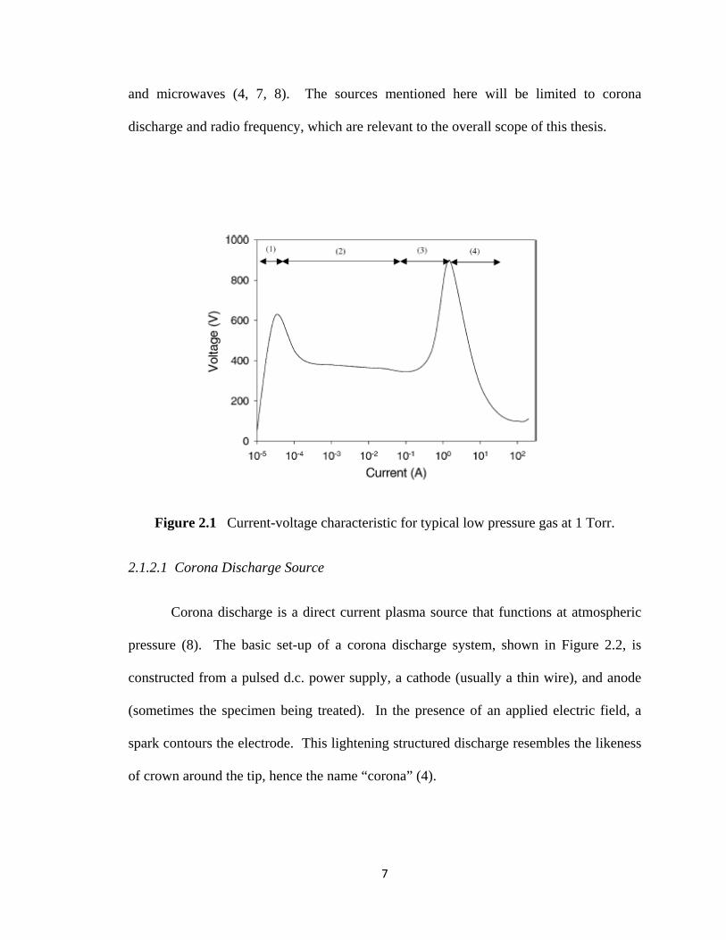
undergo four phases of discharge, 1) Townshend discharge (dark) 2)”normal glow” 3)
abnormal glow, and 4) arc discharge, with the later three indicating the type of spark
formation. The current-voltage characteristic for each of these zones is depicted in
Figure 2.1. At atmospheric pressure, there exist two possible glow discharge regimes 1)
corona discharge, where the discharge current is minimal and 2) arc discharge, where
there is sudden concurrent increase in current and decline in voltage (8). The energy
needed to strip electrons from particles of gas to yield excited molecular or ionic species
can be supplied by an array of sources, including direct current (d.c.), radio frequencies,
and microwaves (4, 7, 8). The sources mentioned here will be limited to corona
discharge and radio frequency, which are relevant to the overall scope of this thesis.
Figure 2.1 Current-voltage characteristic for typical low pressure gas at 1 Torr.
2.1.2.1 Corona Discharge Source
Corona discharge is a direct current plasma source that functions at atmospheric
pressure (8). The basic set-up of a corona discharge system, shown in Figure 2.2, is
constructed from a pulsed d.c. power supply, a cathode (usually a thin wire), and anode
(sometimes the specimen being treated). In the presence of an applied electric field, a
spark contours the electrode. This lightening structured discharge resembles the likeness
of crown around the tip, hence the name “corona” (4).
7
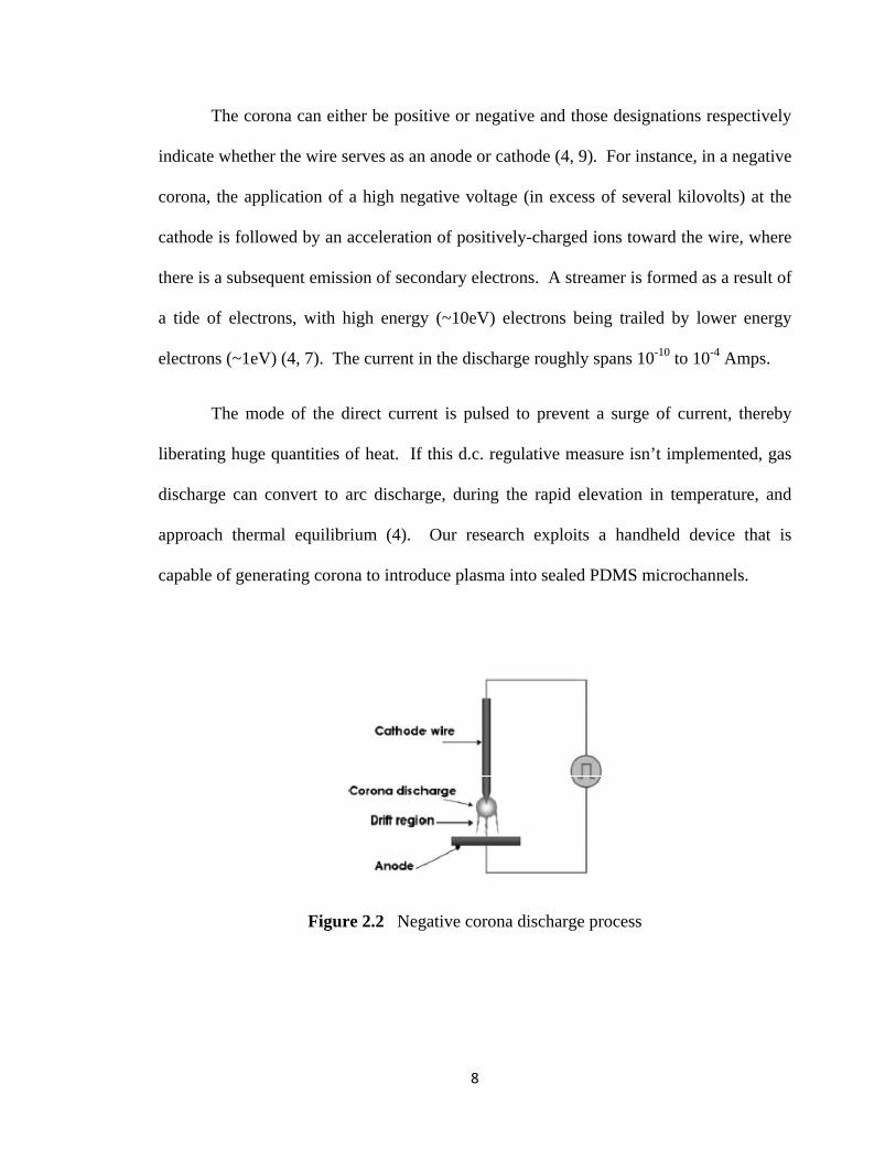
The corona can either be positive or negative and those designations respectively
indicate whether the wire serves as an anode or cathode (4, 9). For instance, in a negative
corona, the application of a high negative voltage (in excess of several kilovolts) at the
cathode is followed by an acceleration of positively-charged ions toward the wire, where
there is a subsequent emission of secondary electrons. A streamer is formed as a result of
a tide of electrons, with high energy (~10eV) electrons being trailed by lower energy
electrons (~1eV) (4, 7). The current in the discharge roughly spans 10-10 to 10-4 Amps.
The mode of the direct current is pulsed to prevent a surge of current, thereby
liberating huge quantities of heat. If this d.c. regulative measure isn’t implemented, gas
discharge can convert to arc discharge, during the rapid elevation in temperature, and
approach thermal equilibrium (4). Our research exploits a handheld device that is
capable of generating corona to introduce plasma into sealed PDMS microchannels.
Figure 2.2 Negative corona discharge process
8
9
2.1.2.2. Radio Frequency (r.f.) Discharge Source
Radio frequencies (r.f.), usually ranging from 1kHz – 103kHz, supply alternating
currents (a.c.), and thus a.c. discharges. However, the standard r.f. value is 15.56 kHz,
because it has been determined by worldwide communications authorities to be the
highest acceptable value not leading to interference of communications. A.c. discharges,
unlike d.c. discharges, exclude the accumulation of charge on a cathode or anode, which
will quench discharge. Charge accumulation usually results when at least one of the
electrodes is a non-conductive material that coats the opposing electrode when subjected
to d.c. power. If the direction of the voltage is continuously switched midway through
the discharge process, build up of particular charge on a given electrode during one
phase, is to some extent counteracted by the opposite charge during the next phase (4).
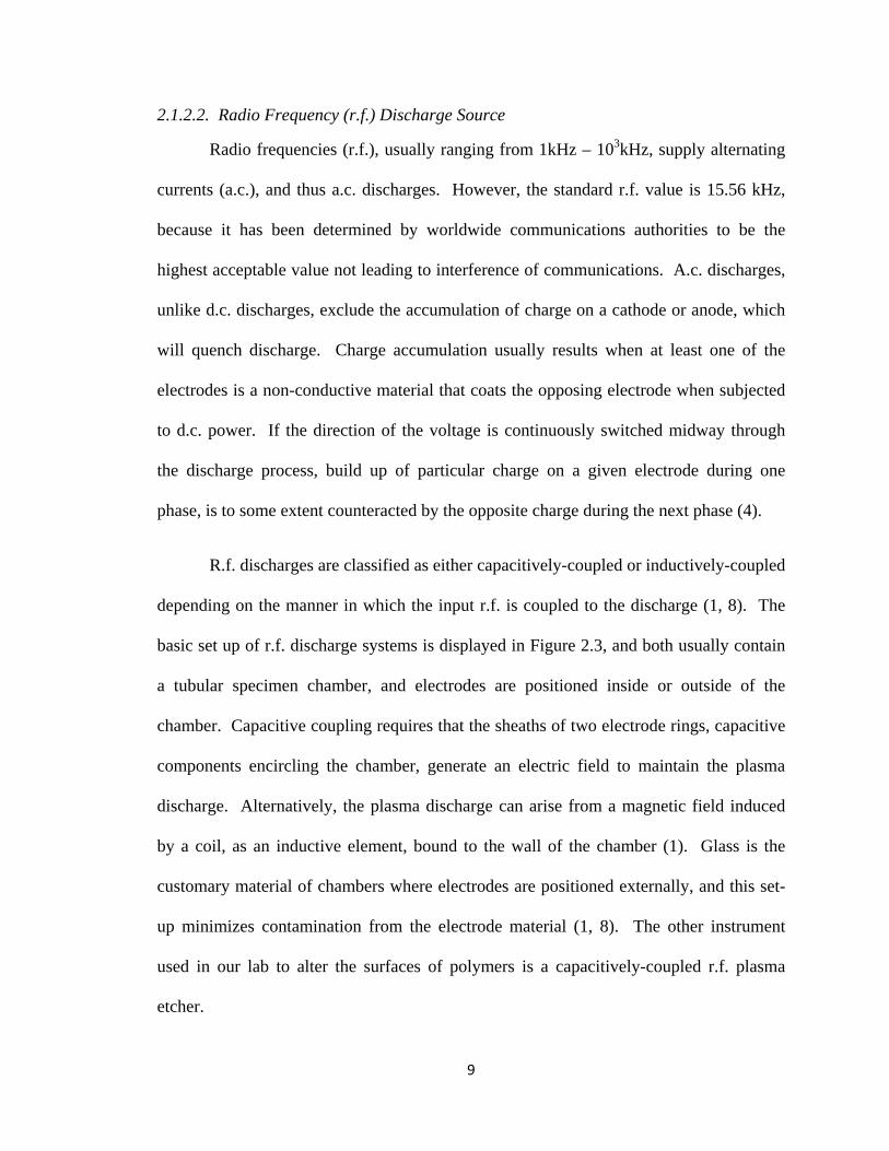
R.f. discharges are classified as either capacitively-coupled or inductively-coupled
depending on the manner in which the input r.f. is coupled to the discharge (1, 8). The
basic set up of r.f. discharge systems is displayed in Figure 2.3, and both usually contain
a tubular specimen chamber, and electrodes are positioned inside or outside of the
chamber. Capacitive coupling requires that the sheaths of two electrode rings, capacitive
components encircling the chamber, generate an electric field to maintain the plasma
discharge. Alternatively, the plasma discharge can arise from a magnetic field induced
by a coil, as an inductive element, bound to the wall of the chamber (1). Glass is the
customary material of chambers where electrodes are positioned externally, and this set-
up minimizes contamination from the electrode material (1, 8). The other instrument
used in our lab to alter the surfaces of polymers is a capacitively-coupled r.f. plasma
etcher.
Figure 2.3. Schematic of a) capacitively coupled and b) inductively coupled r.f. discharge system.
2.2. Surface Modification of Materials with Plasma
There is a perpetual drive to miniaturize electronic components for increased
efficiency and reduced cost of integrated circuits, which are the fundamental elements in
a vast array of electronic products. Advancements in microelectronics have been
bolstered with the use of plasma technology, given that plasma is involved in several
electronic substrate development phases, including material deposition (e.g. epitaxial
growth of layers on base substrate), pattern mask layer etching (e.g. stacked structures
that serve as resisters or capacitors), or surface cleaning (e.g. removing impurities from or
smoothing surfaces) (1).
10
11
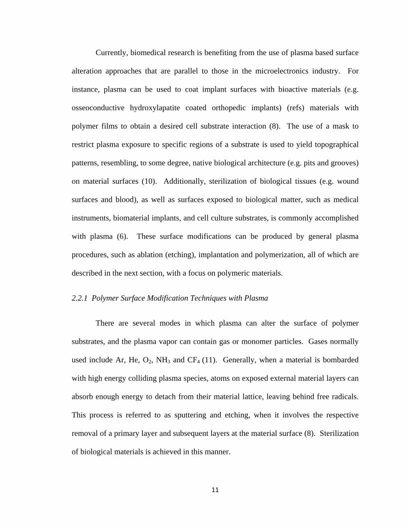
Currently, biomedical research is benefiting from the use of plasma based surface
alteration approaches that are parallel to those in the microelectronics industry. For
instance, plasma can be used to coat implant surfaces with bioactive materials (e.g.
osseoconductive hydroxylapatite coated orthopedic implants) (refs) materials with
polymer films to obtain a desired cell substrate interaction (8). The use of a mask to
restrict plasma exposure to specific regions of a substrate is used to yield topographical
patterns, resembling, to some degree, native biological architecture (e.g. pits and grooves)
on material surfaces (10). Additionally, sterilization of biological tissues (e.g. wound
surfaces and blood), as well as surfaces exposed to biological matter, such as medical
instruments, biomaterial implants, and cell culture substrates, is commonly accomplished
with plasma (6). These surface modifications can be produced by general plasma
procedures, such as ablation (etching), implantation and polymerization, all of which are
described in the next section, with a focus on polymeric materials.
2.2.1 Polymer Surface Modification Techniques with Plasma
There are several modes in which plasma can alter the surface of polymer
substrates, and the plasma vapor can contain gas or monomer particles. Gases normally
used include Ar, He, O2, NH3 and CF4 (11). Generally, when a material is bombarded
with high energy colliding plasma species, atoms on exposed external material layers can
absorb enough energy to detach from their material lattice, leaving behind free radicals.
This process is referred to as sputtering and etching, when it involves the respective
removal of a primary layer and subsequent layers at the material surface (8). Sterilization
of biological materials is achieved in this manner.
12
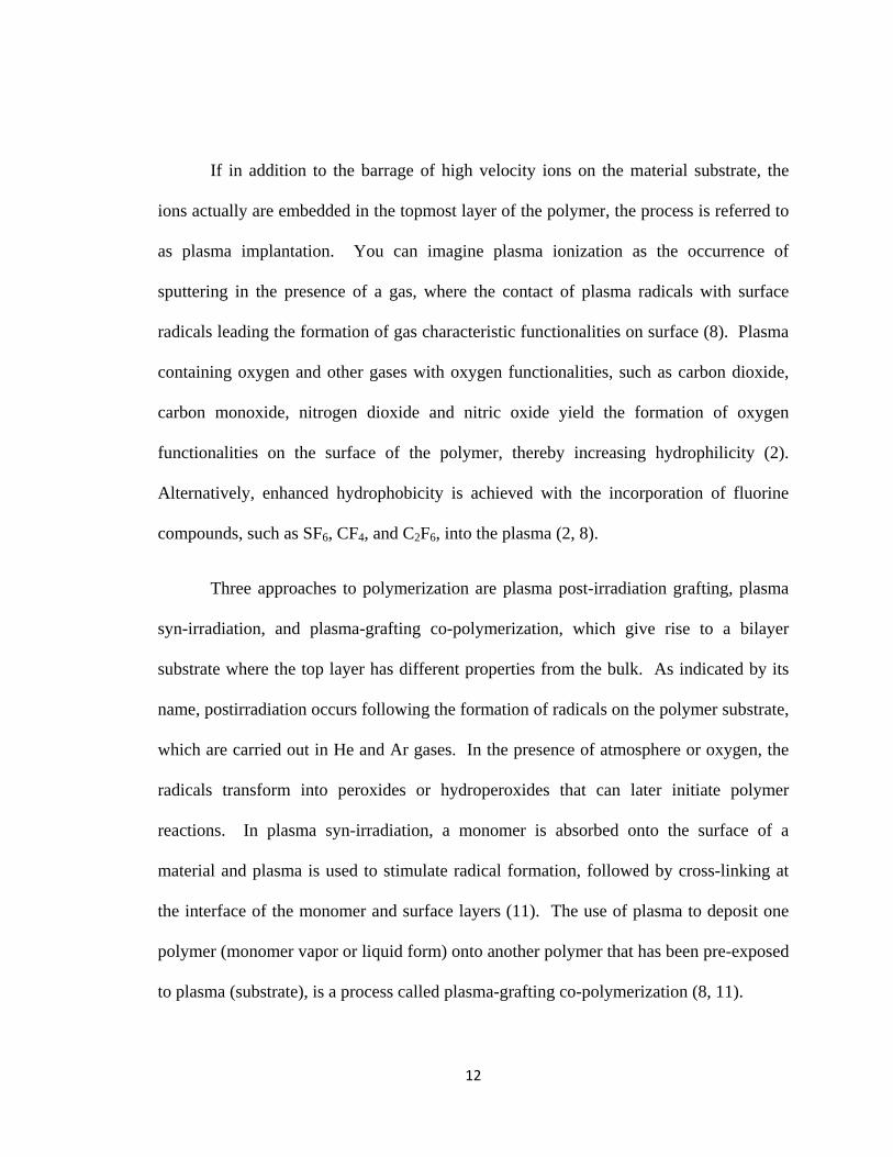
If in addition to the barrage of high velocity ions on the material substrate, the
ions actually are embedded in the topmost layer of the polymer, the process is referred to
as plasma implantation. You can imagine plasma ionization as the occurrence of
sputtering in the presence of a gas, where the contact of plasma radicals with surface
radicals leading the formation of gas characteristic functionalities on surface (8). Plasma
containing oxygen and other gases with oxygen functionalities, such as carbon dioxide,
carbon monoxide, nitrogen dioxide and nitric oxide yield the formation of oxygen
functionalities on the surface of the polymer, thereby increasing hydrophilicity (2).
Alternatively, enhanced hydrophobicity is achieved with the incorporation of fluorine
compounds, such as SF6, CF4, and C2F6, into the plasma (2, 8).
Three approaches to polymerization are plasma post-irradiation grafting, plasma
syn-irradiation, and plasma-grafting co-polymerization, which give rise to a bilayer
substrate where the top layer has different properties from the bulk. As indicated by its
name, postirradiation occurs following the formation of radicals on the polymer substrate,
which are carried out in He and Ar gases. In the presence of atmosphere or oxygen, the
radicals transform into peroxides or hydroperoxides that can later initiate polymer
reactions. In plasma syn-irradiation, a monomer is absorbed onto the surface of a
material and plasma is used to stimulate radical formation, followed by cross-linking at
the interface of the monomer and surface layers (11). The use of plasma to deposit one
polymer (monomer vapor or liquid form) onto another polymer that has been pre-exposed
to plasma (substrate), is a process called plasma-grafting co-polymerization (8, 11).
13
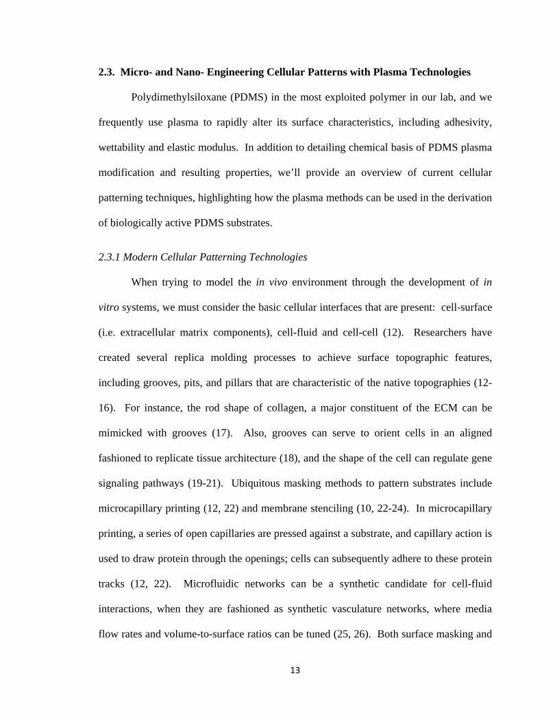
2.3. Micro- and Nano- Engineering Cellular Patterns with Plasma Technologies
Polydimethylsiloxane (PDMS) in the most exploited polymer in our lab, and we
frequently use plasma to rapidly alter its surface characteristics, including adhesivity,
wettability and elastic modulus. In addition to detailing chemical basis of PDMS plasma
modification and resulting properties, we’ll provide an overview of current cellular
patterning techniques, highlighting how the plasma methods can be used in the derivation
of biologically active PDMS substrates.
2.3.1 Modern Cellular Patterning Technologies
When trying to model the in vivo environment through the development of in
vitro systems, we must consider the basic cellular interfaces that are present: cell-surface
(i.e. extracellular matrix components), cell-fluid and cell-cell (12). Researchers have
created several replica molding processes to achieve surface topographic features,
including grooves, pits, and pillars that are characteristic of the native topographies (12-
16). For instance, the rod shape of collagen, a major constituent of the ECM can be
mimicked with grooves (17). Also, grooves can serve to orient cells in an aligned
fashioned to replicate tissue architecture (18), and the shape of the cell can regulate gene
signaling pathways (19-21). Ubiquitous masking methods to pattern substrates include
microcapillary printing (12, 22) and membrane stenciling (10, 22-24). In microcapillary
printing, a series of open capillaries are pressed against a substrate, and capillary action is
used to draw protein through the openings; cells can subsequently adhere to these protein
tracks (12, 22). Microfluidic networks can be a synthetic candidate for cell-fluid
interactions, when they are fashioned as synthetic vasculature networks, where media
flow rates and volume-to-surface ratios can be tuned (25, 26). Both surface masking and
14
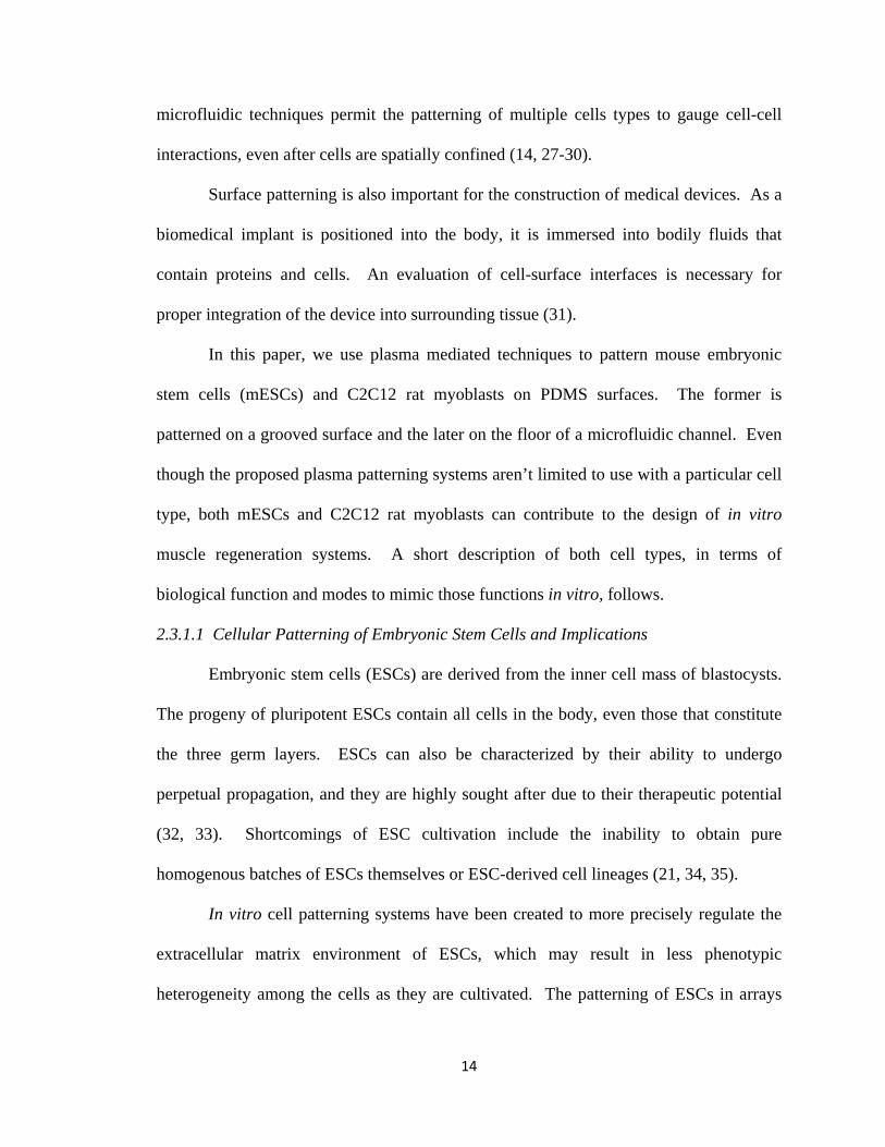
microfluidic techniques permit the patterning of multiple cells types to gauge cell-cell
interactions, even after cells are spatially confined (14, 27-30).
Surface patterning is also important for the construction of medical devices. As a
biomedical implant is positioned into the body, it is immersed into bodily fluids that
contain proteins and cells. An evaluation of cell-surface interfaces is necessary for
proper integration of the device into surrounding tissue (31).
In this paper, we use plasma mediated techniques to pattern mouse embryonic
stem cells (mESCs) and C2C12 rat myoblasts on PDMS surfaces. The former is
patterned on a grooved surface and the later on the floor of a microfluidic channel. Even
though the proposed plasma patterning systems aren’t limited to use with a particular cell
type, both mESCs and C2C12 rat myoblasts can contribute to the design of in vitro
muscle regeneration systems. A short description of both cell types, in terms of
biological function and modes to mimic those functions in vitro, follows.
2.3.1.1 Cellular Patterning of Embryonic Stem Cells and Implications
Embryonic stem cells (ESCs) are derived from the inner cell mass of blastocysts.
The progeny of pluripotent ESCs contain all cells in the body, even those that constitute
the three germ layers. ESCs can also be characterized by their ability to undergo
perpetual propagation, and they are highly sought after due to their therapeutic potential
(32, 33). Shortcomings of ESC cultivation include the inability to obtain pure
homogenous batches of ESCs themselves or ESC-derived cell lineages (21, 34, 35).
In vitro cell patterning systems have been created to more precisely regulate the
extracellular matrix environment of ESCs, which may result in less phenotypic
heterogeneity among the cells as they are cultivated. The patterning of ESCs in arrays
15
has been proposed as a method to robustly determine the effects of cell-cell interactions
(specifically signaling) (36) or cell-surface interactions (on various biomaterial
compositions (37) and of particular topographic sequences (38)) on the self-renewal
efficiency of cells. Recently, McFarlin et al. demonstrated than nanometer square
gratings promoted self-renewal or differentiation of human embryonic stem cells (hES)
respectively in the presence or absence of pluripotent factors (39). Grecht et al.
suggested that actin agents are required for nanometer gratings to contribute to reduced
proliferation and elongated morphology of hESs (40).
2.3.1.2 Cellular Patterning of C2C12 Myoblasts for Muscle Regeneration
Devising muscle regeneration systems is important for remedying muscle injuries
and several myopathies, including muscular dystrophy, prolonged denervation, and tumor
ablation (41-43). The fusion of several aligned myoblasts comprises a multinucleated
myotube, and a bundle of myotubes form muscle fibers that give rise to skeletal muscle
(17, 42-45). In the event that the skeletal muscle tissue is damaged, satellite myoblasts,
or muscle stem cells, will migrate to and restructure the atrophied region (44, 46). The
C2C12 rat myoblasts cell line is composed of satellite myoblast-like cells derived from
C3H mouse skeletal muscle. Even though this cell line is well established and defined,
primary myoblasts are known to more closely resemble developing muscle tissue (44). In
our experiments, we opt for the C2C12 cell line because of its accessibility and ease of
use.
There is a unanimous belief that initial parallel alignment of myoblast is
prerequisite to the in vitro formation of myofibers (17, 42-45, 47, 48), the smallest
contractile structures (43). Numerous in vitro systems have been employed to replicate
16
this parallel orientation (17, 41-44, 46, 47, 49-51), which can serve to improve the design
of muscle scaffolds or screen drug therapies. Shimizu et al. demonstrated a simply
technique to align myoblasts by uniaxially scraping the PDMS surface with sandpaper,
iron blocks and diamond suspension abrasives (42). Li et al cultured C2C12 rat
myoblasts on highly elongated collagen islands and found that the cell-cell contact and
alignment led to enhance dystrophin (structural component necessary for transmission of
muscle forces) expression in comparison to smooth substrates (43). To further increase
regenerative potential, C2C12 rat myoblasts have even been aligned on biodegradable
substrates (47), and geometric helices have been shown to induce long range order of
myotubes and effect degrees of postsynaptic differentiation (17). Additionally,
mechanical and electrical stimuli contribute to myoblast alignment and their generation
into muscle precursor cells (46).
Microfluidics also offers an alternative or complimentary mode to cell surface
patterning for the evaluation of muscle tissue systems. Recently, Tourouskaia et al.
created an in-vitro long term perfusion device in which agrin could be delivered over
identical parallel arrays of myotubes. Construction of the device first involved the
plasma mediated patterning of alternating matrigel (cell permissive) and interpenetrating
network (cell repellent) strips on a glass substrate. A microfluidic device was then
overlaid on the pattern, and it allowed perfusion of the myoblasts as well as laminar flow
of agrin. The technology recreates initial stages of neuromuscular synapse development,
where the microfluidic delivery of agrin over myoblasts imitates the release of agrin from
a neuron synapse to a muscle fiber (51, 52).
17
We’ve developed plasma cellular patterning technologies that make use of mouse
embryonic stem cells and rat myoblast cell types on PDMS surfaces. The next section
will discuss specific mechanisms of plasma modification of PDMS and related cell
patterning applications.
2.3.2 Plasma Modification of PDMS for Surveying Biological Interactions
2.3.2.1 Characteristics of PDMS
PDMS is not only the most exploited polymer in our lab, but also the choice
material for several biological analytical techniques due to its favorable physiochemical
properties: flexibility (elastic modulus ~1MPa) (16, 22, 53), gas permeability (16, 22,
53), optical transparency (16, 22, 54), low toxicity (22, 53, 54), low water permeability
(54), low electrical conductivity (54), high oxidative stability (54) and thermal insulation
(53, 54) . PDMS is biocompatible (16) polymer that has been used in a polymer replica
molding process, known as soft lithography, to caste an assortment of microchannel and
other surface features from original molds (commonly prepared with photolithography)
(22). However, depending on the application, one less desirable trait can be the innate
hydrophobicity (22, 53) of PDMS that is associated with the transient physisorption of
protein (22, 55) and low degree of attachment for some cell types (55). We frequently
use plasma to rapidly alter its surface characteristics, including adhesivity, wettability and
elastic modulus. Here, we wish to apply plasma technology towards the creation of
biologically active PDMS surfaces.
18
2.3.2. Derivation of Biologically Active PDMS Surfaces with Plasma Oxidation
When a plasma treatment is executed in an oxygen-rich environment, the process
is called plasma oxidation, a common method used to modify PDMS surfaces (56, 57). A
reiterating -OSi(CH3)2- unit constitutes the PDMS polymer chain (58, 59). Upon plasma
oxidation, a process that can be carried out in the aforementioned barrel type reactor, the
methyl groups are severed and the silanes along the backbone of the chain are rendered
susceptible to the formation of silanols (SiO-H) groups (59, 60). This transient chemical
alteration of the surface provides three advantages.
One benefit is that amplified hydroxyl concentration increases surfaces energy
(61), resulting in a more hydrophilic surface that increases wetting of PDMS capillary
networks (60), enhances cellular attraction to certain polymers (10, 62-65), or repels
absorption of some analytes (60). Overtime, however, if the surfaces aren’t kept wet,
polymer chains from the bulk PDMS will migrate to the surface, restructuring to its
original hydrophobic state (61, 66). A cluster of experiments exploits the hydrophilic
nature of the oxidized surface to pattern cells. Tourovskaia, et al created circular and
linear arrays of cells that are delimited by nonadhesive domains. The major key to
achieving this patterning was appending cell repellent and plasma degradable polymer
films to a glass substrate. Circular masks or microchannels were used to protect
repellant (IPN) domains from oxygen plasma that unveiled cell attractive regions (bare
glass) (10). Nelson et al. used a protein stamping technique to achieve similar surfaces
that were also comprised of benign and resistant cellular features. Also, cells themselves
display specific interactions with plasma treated surfaces that underwent no prior protein
fouling (67). For instance, Fuard et al. reported increased adhesion, cell membrane
19
protrusions, extent of cell surface coverage and degree of polarization for murine 3T3
fibroblasts on plasma treated substrates as compared to native PDMS substrates (62).
Second, when two oxidized surfaces are brought into conformal contact, a H2O
group condenses as a –Si-O-Si- group forms to affix the surfaces to one another. The
newly formed bond maintains the ability to sustain air pressure of up to 30-50 psi (59).
However, over time, if the surfaces aren’t kept wet or bonded, polymer chains from the
bulk PDMS will migrate to the surface, restructuring to its original hydrophobic state
(60). The microfluidic studies that incorporate the use of bonded PDMS channels are
extensive in the literature, and include manipulation of cellular environments (68),
sensing of biological and chemical analytes (53, 60, 69), and generation of multiple fluid
phases (27), to name a few.
A third less normally emphasized, but highly useful phenomenon, is the brittle
silicate oxide layer that forms on the surface of PDMS after plasma oxidation (56, 70).
The thickness of the oxidized layer can be controlled with prepolymer formulation and
plasma treatment time, among other parameters. With induction of external stresses prior
to or proceeding plasma treatment, one can respectively create periodic wave or v-shaped
grooved surface features. Specifically, when a PDMS substrate is strained during plasma
oxidation, upon relaxation, it will undergo spontaneous wave formation on its uppermost
layer. This buckling effect is due to compressive stresses acting on the newly
synthesized brittle layer, and the original unstrained state of the bulk PDMS is restored
(71). The plasma oxidation induced waves have been used to culture aligned myotubes,
which could be later formed into skeletal muscle constructs that resembled oriented
myofibrils. Also, a continuous wave formation effect is observed when oxidized PDMS
20
slabs are compressed, and disappears upon release of pressure. Using this technique,
Lam et al. have demonstrated reversible alignment of myoblasts along waves (72).
Alternatively, upon the application of strain to an oxidized PDMS substrate, crack or v-
shaped groove features emerge at the surface, with the orientation of the cracks being
perpendicular to the direction of applied strain. The feature formation is also reversible
in this case since the cracks close when the PDMS slabs are liberated from strain. With
the use of this substrate remodeling system, Zhu et al. observed cyclic spreading and
recoiling of myoblasts, with the respective opening and closing of cracks (70). The
ultimate topographical features (i.e. thickness of silicate layer, intergroove spacing, and
wave periodicity) are governed by the modulation of the controllable parameters, which
comprises prepolymer formulation (determines bulk PDMS modulus), length of treatment
time, vacuum pressure, and degree of tensile or compressive strain (70, 72).
2.3.4. Derivation of Biologically Active Polymer Surfaces with Corona Treatment
Corona treatment is a notable contender compared to plasma oxidation in that it offers
researchers practical improvements in terms of the required apparatus and the assortment
of substrate geometries that can be treated (57). Plasma oxidation requires an expensive
and cumbersome vacuum pumping system, which must be maintained regularly. On the
other hand, corona systems present researchers with more economical and user friendly
alternative instrument set-ups that are less cumbersome and can be operated under
atmospheric conditions (73). Corona treatment also has the capability of enriching
PDMS surfaces with silanol moieties (60). Recently, bonding efficiency of PDMS
surfaces and wetting of PDMS channels has been streamlined with the use of a handheld
corona treater. The handheld corona treater, pictured in Figure 2.4, has three accessory
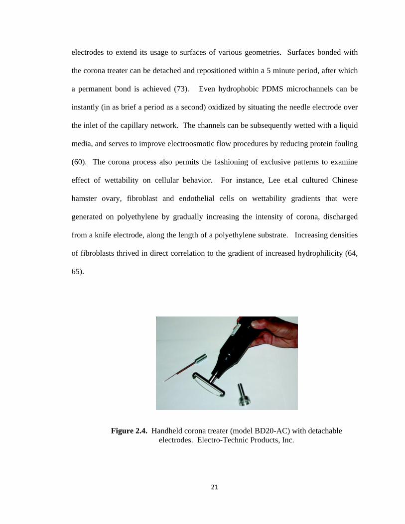
electrodes to extend its usage to surfaces of various geometries. Surfaces bonded with
the corona treater can be detached and repositioned within a 5 minute period, after which
a permanent bond is achieved (73). Even hydrophobic PDMS microchannels can be
instantly (in as brief a period as a second) oxidized by situating the needle electrode over
the inlet of the capillary network. The channels can be subsequently wetted with a liquid
media, and serves to improve electroosmotic flow procedures by reducing protein fouling
(60). The corona process also permits the fashioning of exclusive patterns to examine
effect of wettability on cellular behavior. For instance, Lee et.al cultured Chinese
hamster ovary, fibroblast and endothelial cells on wettability gradients that were
generated on polyethylene by gradually increasing the intensity of corona, discharged
from a knife electrode, along the length of a polyethylene substrate. Increasing densities
of fibroblasts thrived in direct correlation to the gradient of increased hydrophilicity (64,
65).
Figure 2.4. Handheld corona treater (model BD20-AC) with detachable electrodes. Electro-Technic Products, Inc.
21
22
In our lab we propose to expand upon the applications of plasma treatment for
cellular patterning. First, we’ve created a novel system to generate corona induced
wettability gradients within closed microchannels, and the gradients allow for isolation of
cells to select regions on the microchannel floor. Second, we’ve developed a process to
create compression generated cracks in PDMS wells that were oxidized with r.f.
discharge plasma. We then cultured mESCs in the crack patterned wells to determine
effects of coerced cell alignment.
23
2.5. References
1. Rossnagel SM, Cuomo JJ, & Westwood WD (1990) Handbook of plasma
processing technology : fundamentals, etching, deposition, and surface
interactions (Noyes Publications, Park Ridge, N.J., U.S.A.) pp xxiii, 523 p.
2. Inagaki N (1996) Plasma surface modification and plasma polymerization
(Technomic Publishing Co., Lancaster, PA) pp xi, 265 p.
3. Frank-Kamenetskii DA (1972) Plasma--the fourth state of matter (Plenum Press,
New York,) pp viii, 159 p.
4. Bogaerts A, Neyts E, Gijbels R, & van der Mullen J (2002) Gas discharge
plasmas and their applications. Spectrochimica Acta Part B: Atomic Spectroscopy
57(4):609-658.
5. Bonizzoni G & Vassallo E (2002) Plasma physics and technology; industrial
applications. Vacuum 64:327-336.
6. Fridman G, et al. (2008) Applied Plasma Medicine. Plasma Processes and
Polymers 5(6):503-533.
7. Tendero C, Tixier C, Tristant P, Desmaison J, & Leprince P (2006) Atmospheric
pressure plasmas: A review. Spectrochimica Acta Part B: Atomic Spectroscopy
61(1):2-30.
8. Chu PK, Chen JY, Wang LP, & Huang N (2002) Plasma-surface modification of
biomaterials. Materials Science and Engineering: R: Reports 36(5-6):143-206.
9. Chang JS, Lawless PA, & Yamamoto T (1991) Corona discharge processes.
Plasma Science, IEEE Transactions on 19(6):1152-1166.
24
10. Tourovskaia A, et al. (2003) Micropatterns of Chemisorbed Cell Adhesion-
Repellent Films Using Oxygen Plasma Etching and Elastomeric Masks. Langmuir
19(11):4754-4764.
11. Desmet T, et al. (2009) Nonthermal Plasma Technology as a Versatile Strategy
for Polymeric Biomaterials Surface Modification: A Review. Biomacromolecules
10(9):2351-2378.
12. Folch A & Toner M (2003) Microengineering of Cellular Interactions Annual
Review of Biomedical Engineering 2(1):227-256.
13. Charest JL & King WP (2008) Engineering Biomaterial Interfaces Through Micro
and Nano-Patterning. BioNanoFluidic MEMS), pp 251-277.
14. Co CC, Wang Y-C, & Ho C-C (2005) Biocompatible Micropatterning of Two
Different Cell Types. Journal of the American Chemical Society 127(6):1598-
1599.
15. Kapur R, Spargo BJ, Chen M-S, Calvert JM, & Rudolph AS (1996) Fabrication
and selective surface modification of 3-dimensionally textured biomedical
polymers from etched silicon substrates. Journal of Biomedical Materials
Research 33(4):205-216.
16. Park JY, Lee DH, Lee EJ, & Lee S-H (2009) Study of cellular behaviors on
concave and convex microstructures fabricated from elastic PDMS membranes.
Lab on a Chip 9(14):2043-2049.
17. Gingras J, et al. (2009) Controlling the Orientation and Synaptic Differentiation
of Myotubes with Micropatterned Substrates. 97(10):2771-2779.
25
18. Flemming RG, Murphy CJ, Abrams GA, Goodman SL, & Nealey PF (1999)
Effects of synthetic micro- and nano-structured surfaces on cell behavior.
Biomaterials 20(6):573-588.
19. Bettinger CJ, Zhang Z, Gerecht S, Borenstein JT, & Langer R (2008)
Enhancement of In Vitro Capillary Tube Formation by Substrate
Nanotopography. Advanced Materials 20(1):99-103.
20. Kriparamanan R, Aswath P, Zhou A, Tang L, & Nguyen KT (2006)
Nanotopography: Cellular Responses to Nanostructured Materials. Journal of
Nanoscience and Nanotechnology 6:1905-1919.
21. Kulangara K & Leong KW (2009) Substrate topography shapes cell function. Soft
Matter 5(21):4072-4076.
22. Whitesides GM, Ostuni E, Takayama S, Jiang X, & Ingber DE (2001) Soft
Lithography In Biology and Biochemistry. Annual Review of Biomedical
Engineering 3(1):335-373.
23. Folch A, Jo B-H, Hurtado O, Beebe DJ, & Toner M (2000) Microfabricated
elastomeric stencils for micropatterning cell cultures. Journal of Biomedical
Materials Research 52(2):346-353.
24. Jackman RJ, Duffy DC, Cherniavskaya O, & Whitesides GM (1999) Using
Elastomeric Membranes as Dry Resists and for Dry Lift-Off. Langmuir
15(8):2973-2984.
25. Rosano J, et al. (2009) A physiologically realistic in vitro model of microvascular
networks. Biomedical Microdevices 11(5):1051-1057.
26
26. Yeon JH & Park J-K (2007) Microfluidic cell culture systems for cellular
analysis. Biochip Journal 1(1):17-27.
27. Takayama S, et al. (1999) Patterning cells and their environments using multiple
laminar fluid flows in capillary networks. Proceedings of the National Academy
of Sciences of the United States of America 96(10):5545-5548.
28. Yousaf MN, Houseman BT, & Mrksich M (2001) Using electroactive substrates
to pattern the attachment of two different cell populations. Proceedings of the
National Academy of Sciences of the United States of America 98(11):5992-5996.
29. Li Y, et al. (2007) A Method for Patterning Multiple Types of Cells by Using
Electrochemical Desorption of Self-Assembled Monolayers within Microfluidic
Channels13. Angewandte Chemie 119(7):1112-1114.
30. Bhatia SN, Yarmush ML, & Toner M (1997) Controlling cell interactions by
micropatterning in co-cultures: Hepatocytes and 3T3 fibroblasts. Journal of
Biomedical Materials Research 34(2):189-199.
31. Kapur R, Calvert JM, & Rudolph AS (1999) Electrical, Chemical, and
Topological Addressing of Mammalian Cells With Microfabricated Systems.
Journal of Biomechanical Engineering 121(1):65-72.
32. Takahashi K & Yamanaka S (2006) Induction of Pluripotent Stem Cells from
Mouse Embryonic and Adult Fibroblast Cultures by Defined Factors. 126(4):663-
676.
33. MartÃ-nez E, et al. (2009) Stem cell differentiation by functionalized micro- and
nanostructured surfaces. Nanomedicine 4(1):65-82.
27
34. Murray P & Edgar D (2004) The topographical regulation of embryonic stem cell
differentiation. Philosophical Transactions of the Royal Society of London. Series
B: Biological Sciences 359(1446):1009-1020.
35. Saha K, Pollock JF, Schaffer DV, & Healy KE (2007) Designing synthetic
materials to control stem cell phenotype. Current Opinion in Chemical Biology
11(4):381-387.
36. Rosenthal A, Macdonald A, & Voldman J (2007) Cell patterning chip for
controlling the stem cell microenvironment. Biomaterials 28(21):3208-3216.
37. Anderson DG, Levenberg S, & Langer R (2004) Nanoliter-scale synthesis of
arrayed biomaterials and application to human embryonic stem cells. Nat Biotech
22(7):863-866.
38. Markert LDA, et al. (2009) Identification of Distinct Topographical Surface
Microstructures Favoring Either Undifferentiated Expansion or Differentiation of
Murine Embryonic Stem Cells. Stem Cells and Development 18(9):1331-1342.
39. McFarlin DR, Finn KJ, Nealey PF, & Murphy CJ (2009) Nanoscale through
Substratum Topographic Cues Modulate Human Embryonic Stem Cell Self-
Renewal. Journal of Biomimetics, Biomaterials and Tissue Engineering Vol.2:15-
26.
40. Gerecht S, et al. (2007) The effect of actin disrupting agents on contact guidance
of human embryonic stem cells. Biomaterials 28(28):4068-4077.
41. Bian W & Bursac N (2008) Tissue engineering of functional skeletal muscle:
challenges and recent advances. IEEE engineering in medicine and biology
magazine 27(5):109-113.
28
42. Shimizu K, Fujita H, & Nagamori E (2009) Alignment of skeletal muscle
myoblasts and myotubes using linear micropatterned surfaces ground with
abrasives. Biotechnology and Bioengineering 103(3):631-638.
43. Li B, Lin M, Tang Y, Wang B, & Wang JHC (2008) A novel functional
assessment of the differentiation of micropatterned muscle cells. Journal of
Biomechanics 41(16):3349-3353.
44. Bach AD, Beier JP, Stern-Staeter J, & Horch RE (2004) Skeletal muscle tissue
engineering. Journal of Cellular and Molecular Medicine 8(4):413-422.
45. Levenberg S, et al. (2005) Engineering vascularized skeletal muscle tissue. Nat
Biotech 23(7):879-884.
46. Flaibani M, et al. (2009) Muscle Differentiation and Myotubes Alignment Is
Influenced by Micropatterned Surfaces and Exogenous Electrical Stimulation.
Tissue Engineering Part A 15(9):2447-2457.
47. Altomare L, Gadegaard N, Visai L, Tanzi MC, & Farè S (2009) Biodegradable
microgrooved polymeric surfaces obtained by photolithography for skeletal
muscle cell orientation and myotube development. Acta biomaterialia.
48. Huang NF, et al. (2004) Tissue engineering of muscle on micropatterned polymer
films. Engineering in Medicine and Biology Society, 2004. IEMBS '04. 26th
Annual International Conference of the IEEE, pp 4966-4969.
49. Shimizu K, Fujita H, & Nagamori E (Micropatterning of single myotubes on a
thermoresponsive culture surface using elastic stencil membranes for single-cell
analysis. Journal of Bioscience and Bioengineering 109(2):174-178.
29
50. Stern-Straeter J, Riedel F, Bran G, Hörmann K, & Goessler UR (2007) Advances
in Skeletal Muscle Tissue Engineering. In Vivo 21(3):435-444.
51. Tourovskaia A, Li N, & Folch A (2008) Localized Acetylcholine Receptor
Clustering Dynamics in Response to Microfluidic Focal Stimulation with Agrin.
Biophysical Journal 95(6):3009-3016.
52. Tourovskaia A, Figueroa-Masot X, & Folch A (2005) Differentiation-on-a-chip:
A microfluidic platform for long-term cell culture studies. Lab on a Chip 5(1):14-
19.
53. McDonald JC & Whitesides GM (2002) Poly(dimethylsiloxane) as a Material for
Fabricating Microfluidic Devices. Accounts of Chemical Research 35(7):491-499.
54. Yi C, Li C-W, Ji S, & Yang M (2006) Microfluidics technology for manipulation
and analysis of biological cells. Analytica Chimica Acta 560(1-2):1-23.
55. Pakstis LM, et al. (Evaluation of polydimethylsiloxane modification methods for
cell response. Journal of Biomedical Materials Research Part A 92A(2):604-614.
56. K.L. Mills XZ, Shuichi Takayama, M.D. Thouless (2008) The mechanical
properties of a surface-modified layer on polydimethylsiloxane. Journal of
Materials Research 28(1):37-48.
57. Onyiriuka EC, Hersch LS, & Hertl W (1991) Solubilization of corona discharge-
and plasma-treated polystyrene. Journal of Colloid and Interface Science
144(1):98-102.
58. Yong Z, Haji K, Otsubo M, & Honda C (2006) Surface Degradation of Silicone
Rubber Exposed to Corona Discharge. Plasma Science, IEEE Transactions on
34(4):1094-1098.
30
59. Bhattacharya S, Datta A, Berg JM, & Gangopadhyay S (2005) Studies on surface
wettability of poly(dimethyl) siloxane (PDMS) and glass under oxygen-plasma
treatment and correlation with bond strength. Microelectromechanical Systems,
Journal of 14(3):590-597.
60. Thorslund S & Nikolajeff F (2007) Instant oxidation of closed microchannels.
Journal of Micromechanics and Microengineering 17:N16-N21.
61. Kim J, Chaudhury MK, & Owen MJ (2006) Modeling hydrophobic recovery of
electrically discharged polydimethylsiloxane elastomers. Journal of Colloid and
Interface Science 293(2):364-375.
62. Fuard D, Tzvetkova-Chevolleau T, Decossas S, Tracqui P, & Schiavone P
(Optimization of poly-di-methyl-siloxane (PDMS) substrates for studying cellular
adhesion and motility. Microelectronic Engineering 85(5-6):1289-1293.
63. Jong-Hwa C, et al. (2004) Proliferation rate of fibroblast cells on polyethylene
surfaces with wettability gradient. Journal of Applied Polymer Science 92(1):599-
606.
64. Lee JH, Khang G, Lee JW, & Lee HB (1998) Interaction of Different Types of
Cells on Polymer Surfaces with Wettability Gradient. Journal of Colloid and
Interface Science 205(2):323-330.
65. Lee SJ, Khang G, Lee YM, & Lee HB (2003) The effect of surface wettability on
induction and growth of neurites from the PC-12 cell on a polymer surface.
Journal of Colloid and Interface Science 259(2):228-235.
31
66. Kim J, Chaudhury MK, & Owen MJ (2000) Hydrophobic Recovery of
Polydimethylsiloxane Elastomer Exposed to Partial Electrical Discharge. Journal
of Colloid and Interface Science 226(2):231-236.
67. Nelson CM, Raghavan S, Tan JL, & Chen CS (2002) Degradation of
Micropatterned Surfaces by Cell-Dependent and -Independent
Processes†Langmuir 19(5):1493-1499.
68. Rhee SW, et al. (2005) Patterned cell culture inside microfluidic devices. Lab on
a Chip 5(1):102-107.
69. Fujii T (2002) PDMS-based microfluidic devices for biomedical applications.
Microelectronic Engineering 61-62:907-914.
70. Zhu X, et al. (2005) Fabrication of reconfigurable protein matrices by cracking.
Nat Mater 4(5):403-406.
71. Jiang X, et al. (2002) Controlling Mammalian Cell Spreading and Cytoskeletal
Arrangement with Conveniently Fabricated Continuous Wavy Features on
Poly(dimethylsiloxane). Langmuir 18(8):3273-3280.
72. Lam MT, Clem WC, & Takayama S (2008) Reversible on-demand cell alignment
using reconfigurable microtopography. Biomaterials 29(11):1705-1712.
73. Haubert K, Drier T, & Beebe D (2006) PDMS bonding by means of a portable,
low-cost corona system. Lab on a Chip 6(12):1548-1549.
CHAPTER 3
Guided Corona Generates Wettability Patterns that Selectively Direct Cell Attachment Inside Closed
Microchannels
3.1 Introduction
The ability to pattern proteins and cells inside microchannels has been shown to
be important in studying skeletal myotube formation from myoblasts (1), engineering
cardiac muscle (2), examining the effect of shear flow direction on endothelial cell
behavior (3) and guiding neuron growth (4). A key for broader use of these types of
microchannel-based biological studies using delicate living cells is the ability to quickly
and reliably pattern sterile disposable microchannels. A variety of methods has (the word
variety is singular) been developed for this purpose, including initially patterning
adhesive regions on a substrate prior to overlaying a microfluidic network (1), generation
of multiple external forces (5), or exerting precise control of multiple laminar flow
regimes (6). Although very useful, these methods still require multiple steps, the
production of complex channels, or expensive equipment, which may deter use by non-
microtechnology specialists. Thus, microfludic patterning can benefit from even more
expeditious methods. Here we present a simple technique to generate wettability
domains, within 5 seconds, using an inexpensive (~$500) corona treater. Strategic
32
placement of electrodes and control of discharge voltages allow generation of wettability
patterns, as lines, along the length of one side of a one-inlet one-outlet channel or along
one branch of a one-outlet two-outlet Y-shaped channel. The wettability patterns serve as
a platform for subsequent protein and cell patterns in the microfluidic channel.
Corona discharge has been used for modulating the wettability of polydimethyl
siloxane (PDMS) and polyethylene (PE) surfaces for a variety of chemical and biological
assays (7-11). More recently, the handheld corona device was lauded as a facile tool for
oxidizing bonding faces of PDMS substrates and enhancing electroosmotic flow within
PDMS capillaries (8). Earlier research demonstrated wettability features that support cell
patterning. For example, Tan, et al. demonstrated use of Pluronic molecules to
selectively prevent protein and cell attachment onto hydrophilic surfaces generated by
microcontact printing (12). These methods work very well for generating protein and cell
patterns on flat surfaces, but cannot be translated to the generation of patterns inside
three-dimensional microchannels post channel assembly.
In order to achieve a wettability pattern on the base of PDMS channels, we
applied basic electrochemical principles to construct a simple circuit, depicted in Figure
3.1 that directs corona discharge. For example, to generate wettability patterns along one
side of a simple straight channel, a single secondary hole, machined adjacent to both the
inlet and outlet, symmetrically overlaps the rightmost channel wall. The needle electrode
of the handheld corona device is introduced to the inlet secondary hole, and a metal
conductive post is fitted into the outlet secondary hole. In this setup, a stream of corona
flowing from the electrode tip is accelerated to the metal post, which serves as an anode
that triggered the strong ionic attraction. Only the region on the rightmost base of the
33
channel is exposed to the corona and undergoes surface modification, consequently
rendering it hydrophilic. Once wettability patterns are created, Pluronic F127 and
fibronectin were sequentially absorbed to channel surfaces, serving to guide protein
adsorption and cell attachment. The corona treated capillary is incubated with Pluronic
F127, a difunctional block copolymer that strongly adheres to untreated regions and
deters protein fouling. Fibronectin, in its subsequent application to the surface, binds
only to the corona exposed areas. Lastly, C2C12 rat myoblasts introduced in the system
serve to demarcate the original corona fingerprint.
The key to successful protein and cell patterning with this method lies in the
ability to manipulate the corona discharge to generate desired wettability patterns. This
manuscript describes the critical parameters along with some basic theory for reliable and
versatile generation of wettability patterns inside microchannel using corona.
3.2 Experimental Procedures
3.2.1 Microfluidic Device Fabrication
A silicon mold of a single linear microfluidic channel was created using common
photolithography techniques. An AUTOCAD program was used to draft 2cm x 2mm (l x
w) dimensions in a mask, which was transferred to a film transparency with a plotter at
20,000dpi. A 200µm layer of negative SU8-2075 photoresist was spun onto a silicon
wafer and baked. The mask was aligned over the coated wafer. An UV light was
activated and passed through the mask, hardening the channel features. Crosslinking of
the photoresist was ensured with post exposure baking, and uncrosslinked regions were
later dissolved with SU-8 developer. The processed silicon mold was placed in a vacuum
34
chamber with few drops of (tridecafl uoro-1,1,2,2-tetrahydrooctyl)-1-trichlorosilane to
create a thin coating to facilitate removal of casted replicas.
Polydimethylsiloxane (PDMS) prepolymer (Sylgard 184, Dow-Corning), was
prepared from 10 parts elastomer base and 1 part curing agent, and the resulting mixture
was degassed under vacuum. Polystyrene petri-dishes, with a 6cm diameter, were
spincoated with 1.5mL of the prepolymer mixture and allowed to partially cure for 24
hours at room temperature. Additional polymer mixture was poured over the silicon
mold and cured for 2 hours at 60oC. Biopsy punches were used to machine two holes at
either end of the channel along the right wall. Specifically, one 1.5mm-dia hole
symmetrically overlapped the right channel wall and the other 3mm-dia hole spanned the
2mm channel width, while slightly overlapping the smaller hole. An identically
positioned set of holes was (the subject of the sentence is “set”, which is singular) formed
at the opposing end of the channel. PDMS channel replicas were pressed against the
surfaces of the PDMS coated dishes allow contact adherence. Care was taken to remove
all air spaces in bonded regions and a small amount of prepolymer was used to outline the
PDMS replicas to prevent delamination. The complete devices were cured at 60oC for a
minimum of 2 hours. Note: Partial curing of the PDMS layer on the Petri-dish improves
adhesion durability upon complete curing.
In some instances, the channel sizes were truncated to a length of 0.5 cm and 1.0
cm. This was accomplished by placing a third hole beneath an existing set of holes,
defining desired length, on one end of the channel. The device was bonded as described
above and cured for 1 hour. In order to prepare shorter channel, spare PDMS fluid mix
was injected into the third hole and allowed to fill the channel just until the set of
35
overlapping holes was reached, and the devices were cured at 60oC, in a vertical channel
position, for at least 2 additional hours.
Channels were irreversibly bound to the PDMS coated Petri-dishes without
sealing the edges. These set of devices were reserved for later analysis with an Atomic
Force Microscope.
3.2.2 Biased In-Channel Corona Etching Technique
The needle electrode of a corona handheld electrode (Electro-Technic Products,
model BD20A) is inserted into the 1.5mm access port at one end of the microchannel,
while a 1.3mm diameter metal post is positioned into the opposing identical port. Magnet
wire is wound securely around 1mm of the free end of a metal post. Six inches of the
wire remained free and the other end was threaded to an opening of a Boston® bulldog
clip (no. 4) attached to the frame of the fume hood, thereby grounding the system. Upon
engaging the power of the corona treater, the expelled stream of corona was aligned and
accelerated, along the channel wall, towards the direction of the metal rod, or metal
anode. A typical treatment consisted of 5 second duration at 50,000 volts (spark length ~
25mm).
3.2.3 C2C12 Cell Cultivation
C2C12 rat myoblasts were expanded in maintenance media, comprised of
DMEM, 10% fetal bovine serum (FBS), Antibiotic-Antimycotic (1X), and 4mM
Glutamax, until 70% confluency was achieved. The myoblasts did not undergo passages
greater than 15. The cells were washed twice with PBS, detached with 0.25% trypsin and
resuspended in a serum free media, comprised of Advanced DMEM, Antibiotic-
Antimycotic (1X), and 4mM Glutamax.
36
A cell suspension, of density 1.5 x 10⁶ cells/mL, was seeded into microfluidic capillaries.
After cells spread to a confluence of at least 70%, myotube formation was induced with
low serum differentiation media, consisting of DMEM, 2% HS, Antibiotic-Antimycotic
(1X), and 4mM Glutamax.
3.2.4 Preferential Cell Adherence
Following corona treatment, microchannels were incubated for 1 hour with either
0.1% Pluronic F127 or 1% bovine serum albumin (BSA), and rinsed with 300uL PBS/cm
channel length once at each opening. Fibronectin (0.1mg/mL) was introduced into the
channel inlets and the Petri-dishes were rocked back and forth by hand (5x) in a manner
to induce slight gravity flow along the length of the channel, ensuring even distribution of
protein. The coated devices were exposed to UV for a period of 30 minutes and
subsequently, rinsed with 150uL PBS/cm length of channel at both openings, filled with
fresh PBS, and incubated at 37oC for at least 15 mins prior to seeding.
Alexa 546 fibrinogen was absorbed to the channel to illuminate the corona
pattern.
3.2.5 Statistical Analysis
Three separate channel lengths (referring to the length between the inlet and
outlet) of 0.5cm, 1cm and 1.5cm were used in this analysis. Width measurements were
obtained at every 0.25cm position between the inlet and outlet of each channel. Values
reported are means ± SD at the indicated positions, and were drawn from 2 runs, each
containing 3 replicates. Statistical analysis was performed using one-way ANOVA, with
37
a value of p < 0.05 assigned as significant. Tukey’s post hoc analysis was executed in the
evident of discovering a significant difference amongst groups.
3.2.6 Atomic Force Microscopy
Some of the PDMS substrates were primed for Atomic Force Microscopy (AFM)
analysis. Two lines, delineating the walls of the microchannel, were scribed on the
bottom of the Petri-dish with permanent marker. Afterwards, the PDMS microchannel
was gently detached from the PDMS coated surface following 5 second corona
patterning. The walls of the Petri dish were removed and a scalpel was used to excise a
flat region of the Petri-dish containing the treated surface. The microchannel was gently
lifted, so as not to delaminate the PDMS film from the Petri-dish surface. A survey of
the topography of the corona treated regions was conducted with the NanoMan AFM,
under tapping mode.
3.3 Results and Discussion
Glow discharge plasma has been exploited to preferentially treat simple channel
networks, with two and three paths, based on channel dimensions and geometry (13), and
also to decipher the shortest path in complex microfluidic mazes and maps (14). Yet, to
our knowledge, there has been no previously documented system that allows selective
plasma etching of the floors of a single linear path microchannel nor the use of resulting
surface treated channels for cellular patterning. Our process possesses the advantage of
ease of use made possible by the handheld corona device. The ability to selectively guide
a corona through a PDMS channel was made possible by the simple circuit assembly,
depicted in Figure 3.1. The metal anode serves to align and attract all corona streams
introduced to the inlet of the microchannel. Since the grounded metal anode is positioned
38
to overlap the wall of the channel, the corona streams float in proximity to the wall of
preference. The set-up does not necessitate controlled atmospheric conditions, but
seclusion of the apparatus in a fume hood is advised to prevent the user’s exposure to
ozone emissions during device operation. A typical treatment consisted of 25,000-50,000
volts for a 5-second duration. The tip of the needle electrode can be placed at the desired
distance from a metal object to achieve a certain spark length. The length of the spark
discharge can be used to approximate the corresponding voltage (1cm yields ~ 25kV), as
noted in the handheld corona operating manual (Electro-Technic Products). The
conformation of the discharge must be linear and not arced which may indicate over-
ionization, or transition into arc discharge (15), and can be corrected by increasing the
distance or decreasing voltage. Figure 3.2 depicts corona discharge over a 1.0 cm one-
inlet-one-outlet channel at a voltage of 25,000 volts. The same method was applied to a
one-inlet-two-outlet Y-shaped channel, where the right-hand directed corona followed the
right wall of the main channel and the rightmost arm.
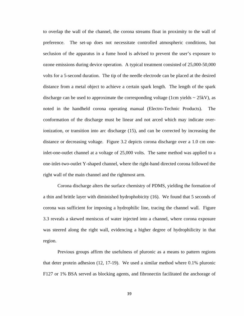
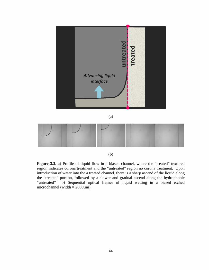
Corona discharge alters the surface chemistry of PDMS, yielding the formation of
a thin and brittle layer with diminished hydrophobicity (16). We found that 5 seconds of
corona was sufficient for imposing a hydrophilic line, tracing the channel wall. Figure
3.3 reveals a skewed meniscus of water injected into a channel, where corona exposure
was steered along the right wall, evidencing a higher degree of hydrophilicity in that
region.
Previous groups affirm the usefulness of pluronic as a means to pattern regions
that deter protein adhesion (12, 17-19). We used a similar method where 0.1% pluronic
F127 or 1% BSA served as blocking agents, and fibronectin facilitated the anchorage of
39
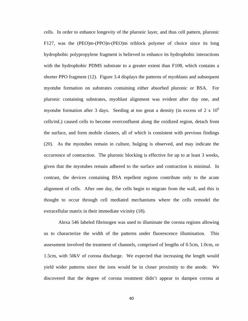
cells. In order to enhance longevity of the pluronic layer, and thus cell pattern, pluronic
F127, was the (PEO)m-(PPO)n-(PEO)m triblock polymer of choice since its long
hydrophobic polypropylene fragment is believed to enhance its hydrophobic interactions
with the hydrophobic PDMS substrate to a greater extent than F108, which contains a
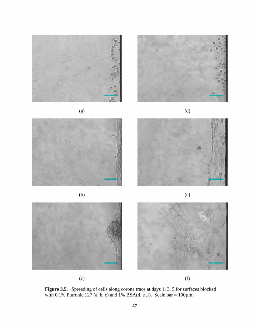
shorter PPO fragment (12). Figure 3.4 displays the patterns of myoblasts and subsequent
myotube formation on substrates containing either absorbed pluronic or BSA. For
pluronic containing substrates, myoblast alignment was evident after day one, and
myotube formation after 3 days. Seeding at too great a density (in excess of 2 x 10⁶
cells/mL) caused cells to become overconfluent along the oxidized region, detach from
the surface, and form mobile clusters, all of which is consistent with previous findings
(20). As the myotubes remain in culture, bulging is observed, and may indicate the
occurrence of contraction. The pluronic blocking is effective for up to at least 3 weeks,
given that the myotubes remain adhered to the surface and contraction is minimal. In
contrast, the devices containing BSA repellent regions contribute only to the acute
alignment of cells. After one day, the cells begin to migrate from the wall, and this is
thought to occur through cell mediated mechanisms where the cells remodel the
extracellular matrix in their immediate vicinity (18).
Alexa 546 labeled fibrinogen was used to illuminate the corona regions allowing
us to characterize the width of the patterns under fluorescence illumination. This
assessment involved the treatment of channels, comprised of lengths of 0.5cm, 1.0cm, or
1.5cm, with 50kV of corona discharge. We expected that increasing the length would
yield wider patterns since the ions would be in closer proximity to the anode. We
discovered that the degree of corona treatment didn’t appear to dampen corona at
40
distances farthest from the inlet, where the spring electrode is placed, but instead
remained relatively constant along the length of the channel, as evidenced in Figure 3.4c.
Figure 3.4b demonstrates our comparisons of pattern width measurements taken half-way
along the wall of 0.5cm, 1.0cm, and 1.5cm long channels, and we found the average
width to be 519.2 ± 65.1, 619.9 ± 42.6, and 817.5 ± 145.8 µM respectively. We notice
that the average width is not significantly different between 0.5cm and 1.0cm and the
widths generated among all channels span. The high variability in the width
measurements for the 1.5cm long channel is attributed to inconsistency of the handheld
corona treater device itself and the stochastic nature of plasma.
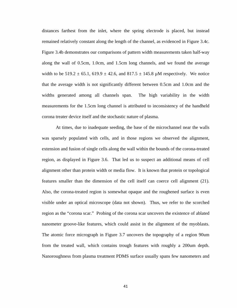
At times, due to inadequate seeding, the base of the microchannel near the walls
was sparsely populated with cells, and in those regions we observed the alignment,
extension and fusion of single cells along the wall within the bounds of the corona-treated
region, as displayed in Figure 3.6. That led us to suspect an additional means of cell
alignment other than protein width or media flow. It is known that protein or topological
features smaller than the dimension of the cell itself can coerce cell alignment (21).
Also, the corona-treated region is somewhat opaque and the roughened surface is even
visible under an optical microscope (data not shown). Thus, we refer to the scorched
region as the “corona scar.” Probing of the corona scar uncovers the existence of ablated
nanometer groove-like features, which could assist in the alignment of the myoblasts.
The atomic force micrograph in Figure 3.7 uncovers the topography of a region 90um
from the treated wall, which contains trough features with roughly a 200um depth.
Nanoroughness from plasma treatment PDMS surface usually spans few nanometers and
41
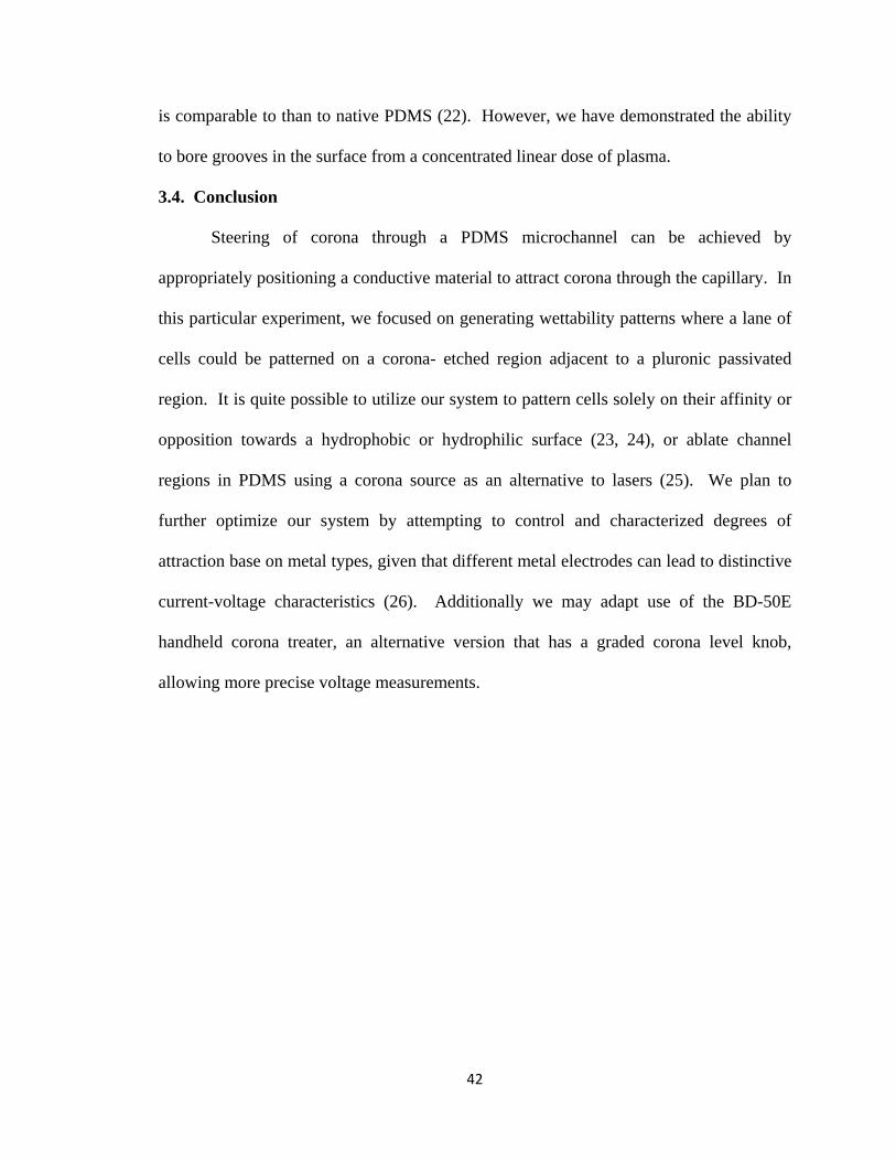
is comparable to than to native PDMS (22). However, we have demonstrated the ability
to bore grooves in the surface from a concentrated linear dose of plasma.
3.4. Conclusion
Steering of corona through a PDMS microchannel can be achieved by
appropriately positioning a conductive material to attract corona through the capillary. In
this particular experiment, we focused on generating wettability patterns where a lane of
cells could be patterned on a corona- etched region adjacent to a pluronic passivated
region. It is quite possible to utilize our system to pattern cells solely on their affinity or
opposition towards a hydrophobic or hydrophilic surface (23, 24), or ablate channel
regions in PDMS using a corona source as an alternative to lasers (25). We plan to
further optimize our system by attempting to control and characterized degrees of
attraction base on metal types, given that different metal electrodes can lead to distinctive
current-voltage characteristics (26). Additionally we may adapt use of the BD-50E
handheld corona treater, an alternative version that has a graded corona level knob,
allowing more precise voltage measurements.
42
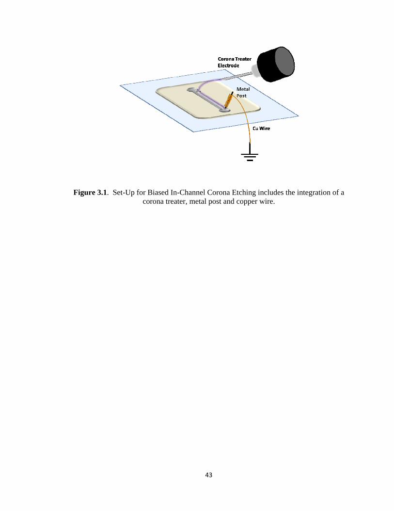
Figure 3.1. Set-Up for Biased In-Channel Corona Etching includes the integration of a corona treater, metal post and copper wire.
43
(a)
(b)
Figure 3.2. a) Profile of liquid flow in a biased channel, where the “treated” textured region indicates corona treatment and the “untreated” region no corona treatment. Upon introduction of water into the a treated channel, there is a sharp ascend of the liquid along the “treated” portion, followed by a slower and gradual ascend along the hydrophobic “untreated” b) Sequential optical frames of liquid wetting in a biased etched microchannel (width = 2000µm).
44
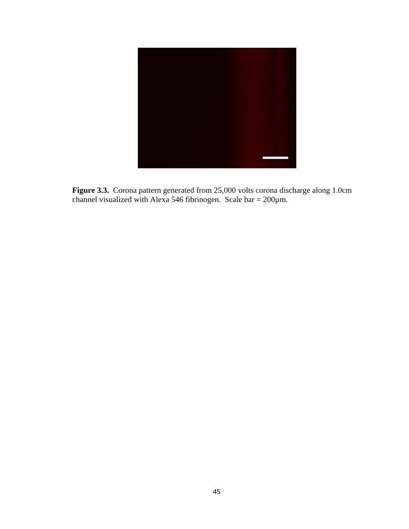
Figure 3.3. Corona pattern generated from 25,000 volts corona discharge along 1.0cm channel visualized with Alexa 546 fibrinogen. Scale bar = 200µm.
45
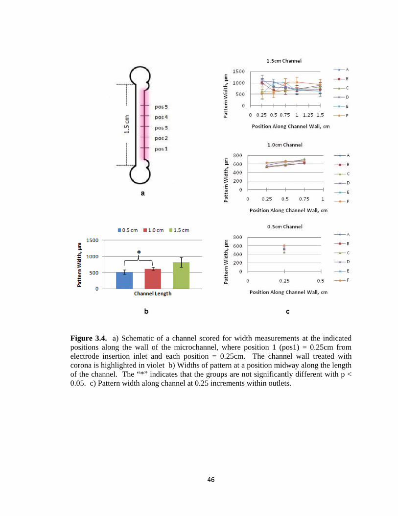
Figure 3.4. a) Schematic of a channel scored for width measurements at the indicated positions along the wall of the microchannel, where position 1 (pos1) = 0.25cm from electrode insertion inlet and each position = 0.25cm. The channel wall treated with corona is highlighted in violet b) Widths of pattern at a position midway along the length of the channel. The “*” indicates that the groups are not significantly different with p < 0.05. c) Pattern width along channel at 0.25 increments within outlets.
46
(a)
(d)
(b)
(e)
(c)
(f)
Figure 3.5. Spreading of cells along corona trace at days 1, 3, 5 for surfaces blocked with 0.1% Pluronic 127 (a, b, c) and 1% BSA(d, e ,f). Scale bar = 100µm.
47
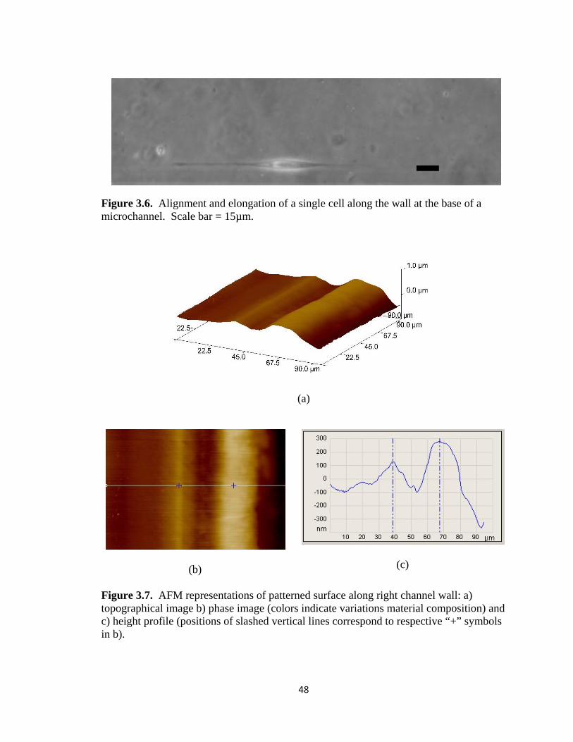
Figure 3.6. Alignment and elongation of a single cell along the wall at the base of a microchannel. Scale bar = 15µm.
(a)
(b)
(c)
Figure 3.7. AFM representations of patterned surface along right channel wall: a) topographical image b) phase image (colors indicate variations material composition) and c) height profile (positions of slashed vertical lines correspond to respective “+” symbols in b).
48
3.5 References
1. Tourovskaia A, Figueroa-Masot X, & Folch A (2005) Differentiation-on-a-chip:
A microfluidic platform for long-term cell culture studies. Lab on a Chip 5(1):14-
19.
2. Khademhosseini A, et al. (2007) Microfluidic patterning for fabrication of
contractile cardiac organoids. Biomedical Microdevices 9(2):149-157.
3. Wu Z, Liu AQ, & Hjort K (2007) Microfluidic continuous particle/cell separation
via electroosmotic-flow-tuned hydrodynamic spreading. Journal of
Micromechanics and Microengineering (10):1992.
4. Rhee SW, et al. (2005) Patterned cell culture inside microfluidic devices. Lab on
a Chip 5(1):102-107.
5. Rhee S, Taylor A, Cribbs D, Cotman C, & Jeon N (2007) External force-assisted
cell positioning inside microfluidic devices. Biomedical Microdevices 9(1):15-23.
6. Takayama S, et al. (1999) Patterning cells and their environments using multiple
laminar fluid flows in capillary networks. Proceedings of the National Academy
of Sciences of the United States of America 96(10):5545-5548.
7. Lucas N, et al. (2009) Microplasma Stamps for Area-Selective Modification of
Polymer Surfaces. Plasma Processes and Polymers 9999(9999):NA.
8. Thorslund S & Nikolajeff F (2007) Instant oxidation of closed microchannels.
Journal of Micromechanics and Microengineering 17:N16-N21.
9. Jong-Hwa C, et al. (2004) Proliferation rate of fibroblast cells on polyethylene
surfaces with wettability gradient. Journal of Applied Polymer Science 92(1):599-
606.
49
10. Lee JH, Khang G, Lee JW, & Lee HB (1998) Interaction of Different Types of
Cells on Polymer Surfaces with Wettability Gradient. Journal of Colloid and
Interface Science 205(2):323-330.
11. Lee SJ, Khang G, Lee YM, & Lee HB (2003) The effect of surface wettability on
induction and growth of neurites from the PC-12 cell on a polymer surface.
Journal of Colloid and Interface Science 259(2):228-235.
12. Tan JL, Liu W, Nelson CM, Raghavan S, & Chen CS (2004) Simple Approach to
Micropattern Cells on Common Culture Substrates by Tuning Substrate
Wettability. Tissue Engineering 10(5-6):865-872.
13. Lim J, Reyes DR, & Manz A (2003) Guiding DC glow discharge in
microchannels. Lab on a Chip 3(3):137-140.
14. Reyes DR, Ghanem MM, Whitesides GM, & Manz A (2002) Glow discharge in
microfluidic chips for visible analog computing. Lab on a Chip 2(2):113-116.
15. Bogaerts A, Neyts E, Gijbels R, & van der Mullen J (2002) Gas discharge
plasmas and their applications. Spectrochimica Acta Part B: Atomic Spectroscopy
57(4):609-658.
16. Kim J & Chaudhury MK (1999) Corona-discharge-induced hydrophobicity loss
and recovery of silicones. Electrical Insulation and Dielectric Phenomena, 1999
Annual Report Conference on, pp 703-706 vol.702.
17. Neff JA, Caldwell KD, & Tresco PA (1998) A novel method for surface
modification to promote cell attachment to hydrophobic substrates. Journal of
Biomedical Materials Research 40(4):511-519.
50
18. Nelson CM, Raghavan S, Tan JL, & Chen CS (2002) Degradation of
Micropatterned Surfaces by Cell-Dependent and -Independent Processes.
Langmuir 19(5):1493-1499.
19. Liu VA, Jastromb WE, & Bhatia SN (2002) Engineering protein and cell
adhesivity using PEO-terminated triblock polymers. Journal of Biomedical
Materials Research 60(1):126-134.
20. Tourovskaia A, et al. (2003) Micropatterns of Chemisorbed Cell Adhesion-
Repellent Films Using Oxygen Plasma Etching and Elastomeric Masks. Langmuir
19(11):4754-4764.
21. MartÃ-nez E, et al. (2009) Stem cell differentiation by functionalized micro- and
nanostructured surfaces. Nanomedicine 4(1):65-82.
22. Hong SM, Kim SH, Kim JH, & Hwang HI (2006) Hydrophilic Surface
Modification of PDMS Using Atmospheric RF Plasma. Journal of Physics:
Conference Series:656.
23. de Silva MN, desai R, & Odde DJ (2004) Micro-Patterning of Animal Cells on
PDMS Substrates in the Presence of Serum without Use of Adhesion Inhibitors.
Biomedical Microdevices 6(3):219-222.
24. Nakazawa K, Izumi Y, & Mori R (2009) Morphological and functional studies of
rat hepatocytes on a hydrophobic or hydrophilic polydimethylsiloxane surface.
(Translated from eng) Acta Biomater 5(2):613-620 (in eng).
25. Qi H, Chen T, Yao L, & Zuo T (2008) Hydrophilicity modification of
poly(methyl methacrylate) by excimer laser ablation and irradiation. Microfluidics
and Nanofluidics 5(1):139-143.
51

52
26. Pontiga F, Soria C, & Castellanos A (2004) Ozone generation in coaxial corona
discharge using different material electrodes. Electrical Insulation and Dielectric
Phenomena, 2004. CEIDP '04. 2004 Annual Report Conference on, pp 568-571.
CHAPTER 4
Induced Elongation of Mouse Embryonic Stem Cells Along Compression-Generated Linear Nanometer
Grooves
4.1 Introduction
Inside the body, cells can navigate a terrain abundant with not only vast
micrometer and nanometer-scale ruggedness, but also varied surface chemistries.
Scientists have developed methods to mimic the architecture of this basement membrane
landscape, where cells decipher signals not only from the surface upon which they may
be bound, but also other components of the cells’ exterior milieu, including neighboring
cells and biomolecules (1-7). It is well known that textured surfaces, including pores,
pillars, depressions and grooves, can serve as a stimulus to mediate a particular cellular
behavior (2, 4, 5). The most commonly used patterns generated in an experimental
context consist of linear grooved arrays, which display a sinusoidal, rectangular or v-
shaped cross section (4, 8). The routine lithography and other etching techniques used to
generate masks for these patterns demand a steep initial cost that increases for more
precise features on a submicron or nanometer scale (4). Here we present a simple and
inexpensive method to generate arrays of nanometer linear v-shaped cracks via
compression of an oxidized polydimethylsiloxane (PDMS) substrate. Additionally, by
53
control of surface chemistry during the fabrication process, we demonstrate patterning of
cell adhesive molecules selectively within the crack features.
Previously our lab developed a “crack fabrication” method with the use of plasma
technology. Upon the oxidation of the PDMS slab, the topmost surface is converted into
a thin brittle silicate layer, distinguishing it from the bulk material, and the thickness of
this superficial layer can span tens to several hundreds of nanometers under appropriate
treatment conditions. Because of the modulus mis-match between the oxidized film and
bulk layers, subsequent application of tensile strain results in the formation of an ordered
array of cracks in a direction perpendicular to that of applied strain. The respective prior
and post application of pluronic and various cell adhesive molecules to the surface, leads
to a pattern of linear protein tracks within the cracks, sufficient for directing the
alignment of cells (9). Despite the notable value of this method, the Microvice holder,
used to hold cracks open, posed limitations in terms of ease of use due in part to its
relative large size compared to that of a standard Petri-dish. Also, the cover glass
positioned over the PDMS well was the sole line of defense against contamination,
proving challenging because during long term culture media could evaporate and loosen
the seal between the cover glass and the substrate. Recently, our lab also described a
method to induce crack features on substrates by application of external compression,
rather than direct tensile strain, onto plasma oxidized PDMS objects. For cubes, the
mechanics responsible for inducing tensile stress required for cracking in the oxidized
layer is due to constraint induced by frictional effects at the contacts during uniaxial
compression. Cracks are formed that align with the direction of compression(10). Here,
we demonstrate how this latter technique to generate crack features on PDMS cubes
54
using external uniaxial compression can be used to generate patterned substrates for
mouse embryonic stem cell (mESC) patterning. The technique uses compact Hoffman
clamps to uniaxially compress plasma oxidized cube-shaped PDMS wells where the
entire set-up can be enclosed in a Petri-dish minimizing contamination and evaporation
hazards.
Embryonic stem cells (ESCs) are highly sought after due to their pluripotent
nature, which allows them to create the multitude of cell types found in the body,
including those derived from the three germ layers (7). The use of ESCs as regenerative
therapies for an assortment of diseases is hampered by conventional processing methods
that give rise to heterogeneous populations(6, 7, 11, 12). In an effort to better understand
and control self-renewal and differentiation conditions, a myriad of mES patterning
techniques has (myriad is singular) been explored. For example, large arrays of ESCs
have been screened for optimal seeding conditions, substrate architectures or polymer
formulations(7, 13, 14). There are also reports of how nanometer grooved substrates can
modulate ESC morphology and self-renewal capacity (7). Recently, McFarlin et al. have
patterned human embryonic stem cells (hESCs) and reported that nanometer grooves
assist in the preservation of pluripotency in the presence of self-renewal factors, but
interestingly promote differentiation in the absence of those same factors (15). Gerecht et
al. demonstrated that nanotopography alone is ineffective in steering alignment of hESCs,
as evidenced by the increase in proliferation and circularity of hES patterned on
nanogratings in the presence of actin-disrupting agents (16). Based on these previous
reports, we thought that it would be interesting to study not only the effect that
nanotopography has on ESCs but the combined effect of nanotopography with adhesive
55
protein patterning. A major challenge was developing a practical method to generate
such substrates with different nanotopographical and nanoadhesive features for ESC
studies.
This chapter details how inexpensive and simple to use Hoffman clamps and
oxidized cube-shaped wells can be used to introduce a linear arrangement of cell
adhesive proteins within nanoscale crack features. Additionally, we investigate the effect
of this system on the alignment of mESCs at variable densities.
4.2 Methods
4.2.1 Cell Culture
Murine embryonic stem cells, of the D3 line (17), were propropaged on 0.1%
porcine gel coated dishes in a LIF enriched media, using a recipe reported elsewhere (18),
with the only modification being that fetal bovine serum was directly replaced with
knockout serum. In some instances, a LIF deprived-medium was employed to stimulate
spontaneous differentiation of mESCs, and the media formulation is the same as that used
for mESC expansion, with LIF being the sole excluded component.
4.2.2 Substrate Preparation
In order to prepare polydimethylsiloxane (Slygard 184, Dow Corning) wells, a
mold was prepared by using UV curing agent to affix 0.6cm x 0.6cm x 0.6cm glass
cubes, with center-to-center separation of 12cm, onto glass microscope slides (Corning,
2947). Two cube patterned glass slides (each containing 18 glass cubes) were adhered to
a square petri-dish with the use of double sided tape to prevent movement during polymer
casting. Sixty grams of 10:1 (elastomer:crosslinking agent) PDMS was poured into the
Petri dishes, so that the final thickness of the base would be approximately 2mm. The
56
dishes were stored at room temperature to allow the prepolymer mixture to degas and
partially cure, and the latter permits enough flexibility for ease of removal. The cube
depression replica was cured for an additional 3 hours at 60oC and 12 hours at 150oC to
fully crosslink the PDMS. The wells were cut so that the wall thickness was
approximately 3mm.
4.2.2 Cell Culture on Compression Generated Cracks
The PDMS wells were exposed to oxygen plasma at 300mTorr for 90seconds.
The wells were inverted and placed on circular openings of the base of a plastic stand, at
a height of ~2cm over a 1:1 (tridecafluoro-1,1,2,2-tetrahydrooctyl)-1-trichlorosilane to
mineral oil mixture inside and vacuum chamber. The samples were subjected to vacuum
at 1.3kPa for a period of 7 minutes. This vapor deposition process results in the
formation of a thin silane film on interior well walls, and the coating serves a binding
agent. The interior surfaces were blocked with 0.1 % Pluronic F108 for 1 hour and rinsed
3 times with distilled water. The wells were allowed to air dry briefly prior to being
compressed.
Hoffman compression clamps, which had been previously sterilized by immersion
into 95% ethanol for at least one hour, were used to exert compressive strain on the wells.
Each PDMS well was centered under the screw between the stationary base and mobile
top bar of the clamp. The screw was gently tightened just enough to restrict movement,
and then further advanced until the desired displacement was achieved. The wells were
rinsed once more with distilled water prior to adding fibronectin (0.1mg/mL). The entire
set up was exposed to Ultraviolet light in a cell culture hood for a minimum of 30
minutes and rinsed with PBS once prior to loading cells.
57
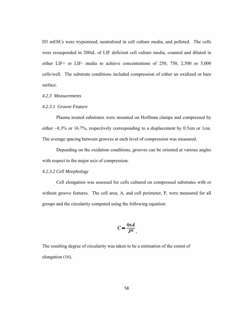
D3 mESCs were trypsinized, neutralized in cell culture media, and pelleted. The cells
were resuspended in 200uL of LIF deficient cell culture media, counted and diluted in
either LIF+ or LIF- media to achieve concentrations of 250, 750, 2,500 or 5,000
cells/well. The substrate conditions included compression of either an oxidized or bare
surface.
4.2.3 Measurements
4.2.3.1 Groove Feature
Plasma treated substrates were mounted on Hoffman clamps and compressed by
either ~8.3% or 16.7%, respectively corresponding to a displacement by 0.5cm or 1cm.
The average spacing between grooves at each level of compression was measured.
Depending on the oxidation conditions, grooves can be oriented at various angles
with respect to the major axis of compression.
4.2.3.2 Cell Morphology
Cell elongation was assessed for cells cultured on compressed substrates with or
without groove features. The cell area, A, and cell perimeter, P, were measured for all
groups and the circularity computed using the following equation:
,
The resulting degree of circularity was taken to be a estimation of the extent of
elongation (16).
58
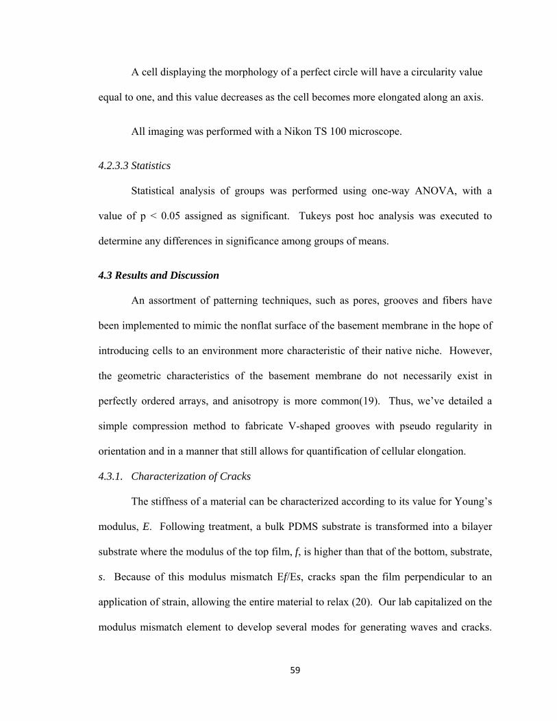
A cell displaying the morphology of a perfect circle will have a circularity value
equal to one, and this value decreases as the cell becomes more elongated along an axis.
All imaging was performed with a Nikon TS 100 microscope.
4.2.3.3 Statistics
Statistical analysis of groups was performed using one-way ANOVA, with a
value of p < 0.05 assigned as significant. Tukeys post hoc analysis was executed to
determine any differences in significance among groups of means.
4.3 Results and Discussion
An assortment of patterning techniques, such as pores, grooves and fibers have
been implemented to mimic the nonflat surface of the basement membrane in the hope of
introducing cells to an environment more characteristic of their native niche. However,
the geometric characteristics of the basement membrane do not necessarily exist in
perfectly ordered arrays, and anisotropy is more common(19). Thus, we’ve detailed a
simple compression method to fabricate V-shaped grooves with pseudo regularity in
orientation and in a manner that still allows for quantification of cellular elongation.
4.3.1. Characterization of Cracks
The stiffness of a material can be characterized according to its value for Young’s
modulus, E. Following treatment, a bulk PDMS substrate is transformed into a bilayer
substrate where the modulus of the top film, f, is higher than that of the bottom, substrate,
s. Because of this modulus mismatch Ef/Es, cracks span the film perpendicular to an
application of strain, allowing the entire material to relax (20). Our lab capitalized on the
modulus mismatch element to develop several modes for generating waves and cracks.
59
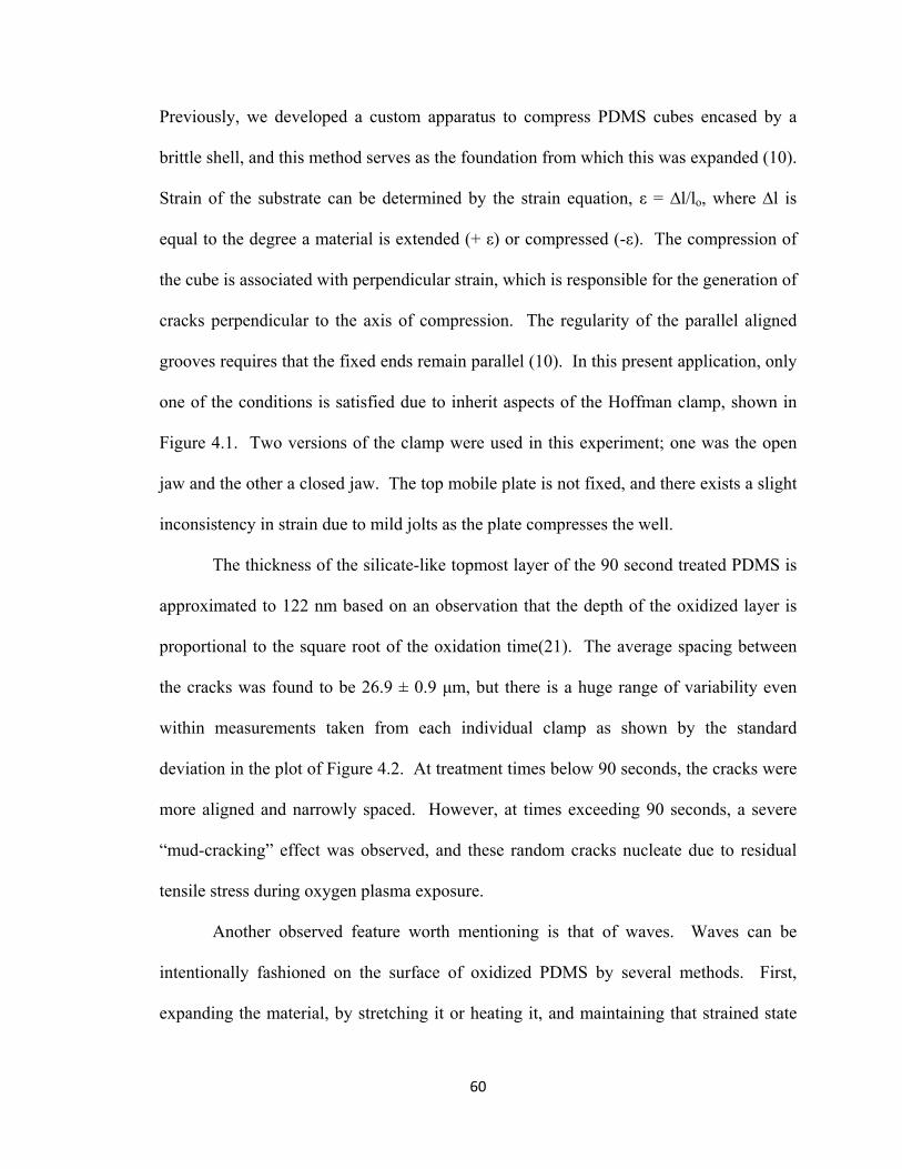
Previously, we developed a custom apparatus to compress PDMS cubes encased by a
brittle shell, and this method serves as the foundation from which this was expanded (10).
Strain of the substrate can be determined by the strain equation, ε = ∆l/lo, where ∆l is
equal to the degree a material is extended (+ ε) or compressed (-ε). The compression of
the cube is associated with perpendicular strain, which is responsible for the generation of
cracks perpendicular to the axis of compression. The regularity of the parallel aligned
grooves requires that the fixed ends remain parallel (10). In this present application, only
one of the conditions is satisfied due to inherit aspects of the Hoffman clamp, shown in
Figure 4.1. Two versions of the clamp were used in this experiment; one was the open
jaw and the other a closed jaw. The top mobile plate is not fixed, and there exists a slight
inconsistency in strain due to mild jolts as the plate compresses the well.
The thickness of the silicate-like topmost layer of the 90 second treated PDMS is
approximated to 122 nm based on an observation that the depth of the oxidized layer is
proportional to the square root of the oxidation time(21). The average spacing between
the cracks was found to be 26.9 ± 0.9 μm, but there is a huge range of variability even
within measurements taken from each individual clamp as shown by the standard
deviation in the plot of Figure 4.2. At treatment times below 90 seconds, the cracks were
more aligned and narrowly spaced. However, at times exceeding 90 seconds, a severe
“mud-cracking” effect was observed, and these random cracks nucleate due to residual
tensile stress during oxygen plasma exposure.
Another observed feature worth mentioning is that of waves. Waves can be
intentionally fashioned on the surface of oxidized PDMS by several methods. First,
expanding the material, by stretching it or heating it, and maintaining that strained state
60
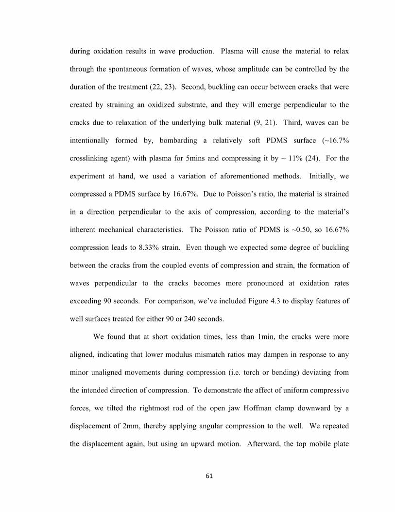
during oxidation results in wave production. Plasma will cause the material to relax
through the spontaneous formation of waves, whose amplitude can be controlled by the
duration of the treatment (22, 23). Second, buckling can occur between cracks that were
created by straining an oxidized substrate, and they will emerge perpendicular to the
cracks due to relaxation of the underlying bulk material (9, 21). Third, waves can be
intentionally formed by, bombarding a relatively soft PDMS surface (~16.7%
crosslinking agent) with plasma for 5mins and compressing it by ~ 11% (24). For the
experiment at hand, we used a variation of aforementioned methods. Initially, we
compressed a PDMS surface by 16.67%. Due to Poisson’s ratio, the material is strained
in a direction perpendicular to the axis of compression, according to the material’s
inherent mechanical characteristics. The Poisson ratio of PDMS is ~0.50, so 16.67%
compression leads to 8.33% strain. Even though we expected some degree of buckling
between the cracks from the coupled events of compression and strain, the formation of
waves perpendicular to the cracks becomes more pronounced at oxidation rates
exceeding 90 seconds. For comparison, we’ve included Figure 4.3 to display features of
well surfaces treated for either 90 or 240 seconds.
We found that at short oxidation times, less than 1min, the cracks were more
aligned, indicating that lower modulus mismatch ratios may dampen in response to any
minor unaligned movements during compression (i.e. torch or bending) deviating from
the intended direction of compression. To demonstrate the affect of uniform compressive
forces, we tilted the rightmost rod of the open jaw Hoffman clamp downward by a
displacement of 2mm, thereby applying angular compression to the well. We repeated
the displacement again, but using an upward motion. Afterward, the top mobile plate
61

was leveled and compression displacement of 1mm was uniformly applied to the well to
open the cracks. The resulting slanted criss-cross pattern is shown in Figure 4.4.
4.3.2. Patterning of mESCs in Compression Wells
The Hoffman clamp is an inexpensive alternative the Micro Vice Holder, which
was originally created for the purpose of mounting specimens over a microscope stage
while they are fixed in a strained state. The H-clamp is also portable and easily fits inside
a standard size Petri dish. Therefore, we are proposing this technique to simplify
cultivation of cells along protein filled cracks.
For a proof of concept experiment, we have seeded mESCs along protein-coated
cracks at various concentrations. Figure 3.5 shows LIF enriched media grown mESCs
added to compressed wells whose bases were either cracked or bare for a period of 4
days. Since the cells were plated on surfaces with adhesive troughs and passivatied
mesas, we considered all elongated cells to be aligned along the grooves of wells. The
cells are driven to align along the grooves, which are covered with fibronectin.
Therefore, we didn’t measure cells for alignment along grooves. Instead, we measured
circularity and used it to gauge the degree of mESC extension. A perfectly round cell
will have a circularity value of 1, and this value decreases as a more elongated
morphology is adapted. The measured values of circularity are displayed in Figure 4.6.
For lower cell densities (250cells/well), circularity appears to gradually increase. On the
other hand, for higher cell densities (750cells/well), the circularity increases and then
remains constant. We would have expected cells grown at higher concentrations to have
a more drastic increase in circularity due to the increased likelihood of cell
agglomeration.
62
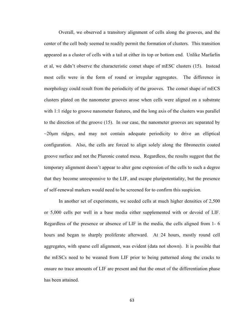
Overall, we observed a transitory alignment of cells along the grooves, and the
center of the cell body seemed to readily permit the formation of clusters. This transition
appeared as a cluster of cells with a tail at either its top or bottom end. Unlike Marfarlin
et al, we didn’t observe the characteristic comet shape of mESC clusters (15). Instead
most cells were in the form of round or irregular aggregates. The difference in
morphology could result from the periodicity of the grooves. The comet shape of mECS
clusters plated on the nanometer grooves arose when cells were aligned on a substrate
with 1:1 ridge to groove nanometer features, and the long axis of the clusters was parallel
to the direction of the groove (15). In our case, the nanometer grooves are separated by
~20μm ridges, and may not contain adequate periodicity to drive an elliptical
configuration. Also, the cells are forced to align solely along the fibronectin coated
groove surface and not the Pluronic coated mesa. Regardless, the results suggest that the
temporary alignment doesn’t appear to alter gene expression of the cells to such a degree
that they become unresponsive to the LIF, and escape pluripotentiality, but the presence
of self-renewal markers would need to be screened for to confirm this suspicion.
In another set of experiments, we seeded cells at much higher densities of 2,500
or 5,000 cells per well in a base media either supplemented with or devoid of LIF.
Regardless of the presence or absence of LIF in the media, the cells aligned from 1- 6
hours and began to sharply proliferate afterward. At 24 hours, mostly round cell
aggregates, with sparse cell alignment, was evident (data not shown). It is possible that
the mESCs need to be weaned from LIF prior to being patterned along the cracks to
ensure no trace amounts of LIF are present and that the onset of the differentiation phase
has been attained.
63
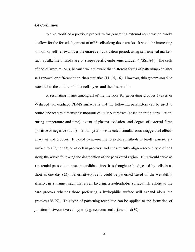
4.4 Conclusion
We’ve modified a previous procedure for generating external compression cracks
to allow for the forced alignment of mES cells along those cracks. It would be interesting
to monitor self-renewal over the entire cell cultivation period, using self renewal markers
such as alkaline phosphatase or stage-specific embryonic antigen 4 (SSEA4). The cells
of choice were mESCs, because we are aware that different forms of patterning can alter
self-renewal or differentiation characteristics (11, 15, 16). However, this system could be
extended to the culture of other cells types and the observation.
A resonating theme among all of the methods for generating grooves (waves or
V-shaped) on oxidized PDMS surfaces is that the following parameters can be used to
control the feature dimensions: modulus of PDMS substrate (based on initial formulation,
curing temperature and time), extent of plasma oxidation, and degree of external force
(positive or negative strain). In our system we detected simultaneous exaggerated effects
of waves and grooves. It would be interesting to explore methods to briefly passivate a
surface to align one type of cell in grooves, and subsequently align a second type of cell
along the waves following the degradation of the passivated region. BSA would serve as
a potential passivation protein candidate since it is thought to be digested by cells in as
short as one day (25). Alternatively, cells could be patterned based on the wettability
affinity, in a manner such that a cell favoring a hydrophobic surface will adhere to the
bare grooves whereas those preferring a hydrophilic surface will expand along the
grooves (26-29). This type of patterning technique can be applied to the formation of
junctions between two cell types (e.g. neuromuscular junctions)(30).
64
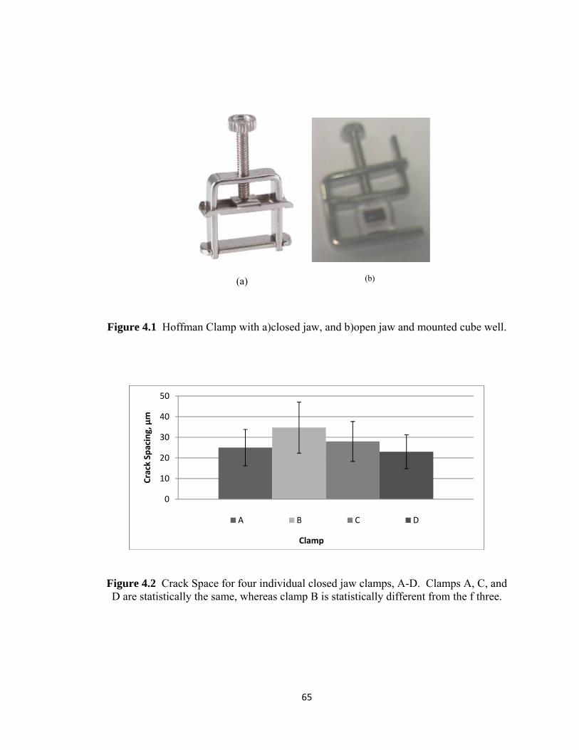
(a)
(b)
Figure 4.1 Hoffman Clamp with a)closed jaw, and b)open jaw and mounted cube well.
0
10
20
30
40
50
Crack Spacing, μm
Clamp
A B C D
Figure 4.2 Crack Space for four individual closed jaw clamps, A-D. Clamps A, C, and D are statistically the same, whereas clamp B is statistically different from the f three.
65
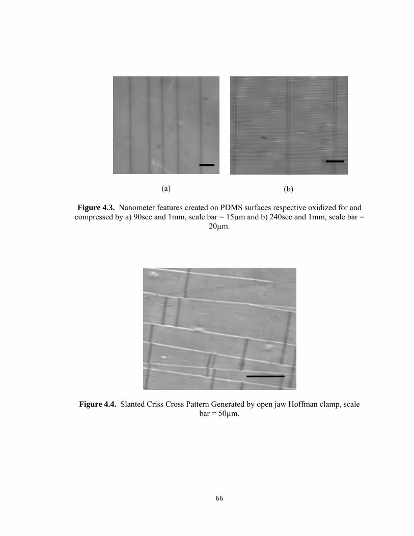
(a)
(b)
Figure 4.3. Nanometer features created on PDMS surfaces respective oxidized for and
compressed by a) 90sec and 1mm, scale bar = 15µm and b) 240sec and 1mm, scale bar = 20µm.
Figure 4.4. Slanted Criss Cross Pattern Generated by open jaw Hoffman clamp, scale bar = 50µm.
66
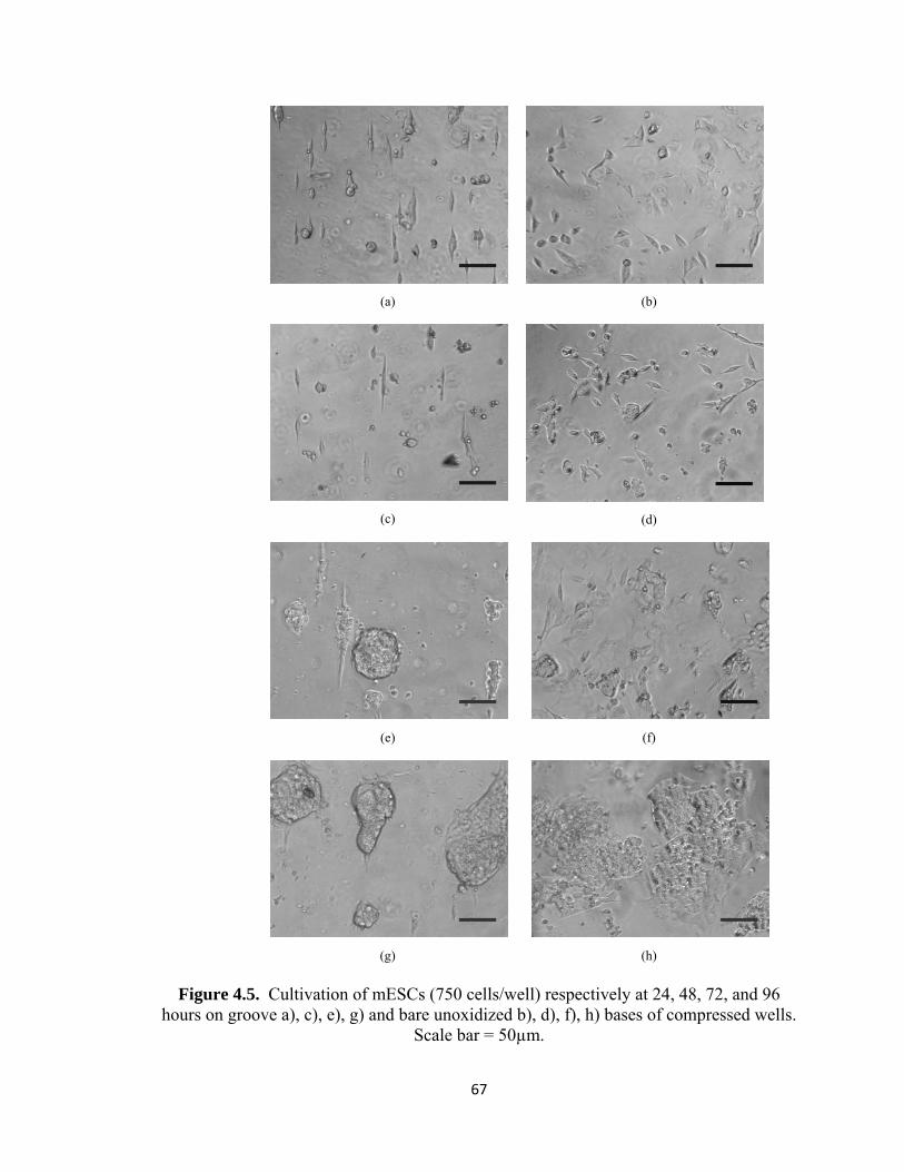
(a)
(b)
(c)
(d)
(e)
(f)
(g)
(h)
Figure 4.5. Cultivation of mESCs (750 cells/well) respectively at 24, 48, 72, and 96 hours on groove a), c), e), g) and bare unoxidized b), d), f), h) bases of compressed wells.
Scale bar = 50µm.
67
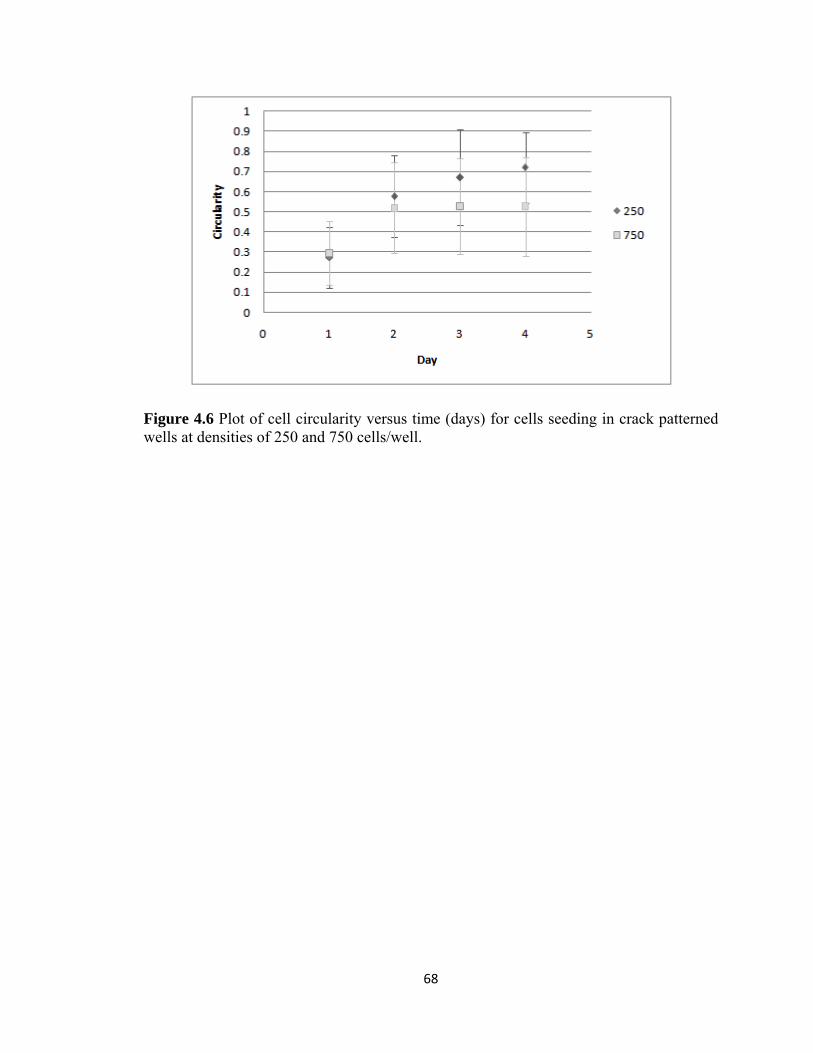
Figure 4.6 Plot of cell circularity versus time (days) for cells seeding in crack patterned wells at densities of 250 and 750 cells/well.
68
4.5 References
1. Bettinger CJ, Zhang Z, Gerecht S, Borenstein JT, & Langer R (2008)
Enhancement of In Vitro Capillary Tube Formation by Substrate
Nanotopography. Advanced Materials 20(1):99-103.
2. Curtis A & C. W (1999) New depths in cell behaviour: reactions of cells to
nanotopography. Biochemical Society Symposia 65:15-26.
3. Curtis A & Wilkinson C (1997) Topographical control of cells. Biomaterials
18(24):1573-1583.
4. Flemming RG, Murphy CJ, Abrams GA, Goodman SL, & Nealey PF (1999)
Effects of synthetic micro- and nano-structured surfaces on cell behavior.
Biomaterials 20(6):573-588.
5. Kriparamanan R, Aswath P, Zhou A, Tang L, & Nguyen KT (2006)
Nanotopography: Cellular Responses to Nanostructured Materials. Journal of
Nanoscience and Nanotechnology 6:1905-1919.
6. Kulangara K & Leong KW (2009) Substrate topography shapes cell function. Soft
Matter 5(21):4072-4076.
7. MartÃ-nez E, et al. (2009) Stem cell differentiation by functionalized micro- and
nanostructured surfaces. Nanomedicine 4(1):65-82.
8. Altomare L, Gadegaard N, Visai L, Tanzi MC, & Farè S (2009) Biodegradable
microgrooved polymeric surfaces obtained by photolithography for skeletal
muscle cell orientation and myotube development. Acta biomaterialia.
9. Zhu X, et al. (2005) Fabrication of reconfigurable protein matrices by cracking.
Nat Mater 4(5):403-406.
69
10. Uchida T, et al. (2009) External Compression-Induced Fracture Patterning on the
Surface of Poly(dimethylsiloxane) Cubes and Microspheres. Langmuir
25(5):3102-3107.
11. Murray P & Edgar D (2004) The topographical regulation of embryonic stem cell
differentiation. Philosophical Transactions of the Royal Society of London. Series
B: Biological Sciences 359(1446):1009-1020.
12. Saha K, Pollock JF, Schaffer DV, & Healy KE (2007) Designing synthetic
materials to control stem cell phenotype. Current Opinion in Chemical Biology
11(4):381-387.
13. Anderson DG, Levenberg S, & Langer R (2004) Nanoliter-scale synthesis of
arrayed biomaterials and application to human embryonic stem cells. Nat Biotech
22(7):863-866.
14. Rossnagel SM, Cuomo JJ, & Westwood WD (1990) Handbook of plasma
processing technology : fundamentals, etching, deposition, and surface
interactions (Noyes Publications, Park Ridge, N.J., U.S.A.) pp xxiii, 523 p.
15. McFarlin DR, Finn KJ, Nealey PF, & Murphy CJ (2009) Nanoscale through
Substratum Topographic Cues Modulate Human Embryonic Stem Cell Self-
Renewal. Journal of Biomimetics, Biomaterials and Tissue Engineering Vol.2:15-
26.
16. Gerecht S, et al. (2007) The effect of actin disrupting agents on contact guidance
of human embryonic stem cells. Biomaterials 28(28):4068-4077.
17. Doetschman TC, Eistetter H, Katz M, Schmidt W, & Kemler R (1985) The in
vitro development of blastocyst-derived embryonic stem cell lines: formation of
70
visceral yolk sac, blood islands and myocardium. Journal of Embryology and
Experimental Morphology 87(1):27-45.
18. Torisawa Y-s, et al. (2007) Efficient formation of uniform-sized embryoid bodies
using a compartmentalized microchannel device. Lab on a Chip 7(6):770-776.
19. Gonsalves KE, Halberstadt CR, Laurencin CT, & Nair LS (2008) Biomedical
Nanostructures. (John Wiley & Sons, Inc.) pp 304-305.
20. Mills KL, Zhu X, Lee D, Takayama S, & Thouless MD (2006) Properties of the
surface-modified layer of plasma-oxidized poly(dimethylsiloxane). Mater. Res.
Soc. Symp. Proc 924:0Z07-08.
21. Mills KL, Zhu X, Takayama S, & Thouless MD (2008) The mechanical
properties of a surface-modified layer on polydimethylsiloxane. Journal of
Materials Research 28(1):37-48.
22. Bowden N, Huck WTS, Paul KE, & Whitesides GM (1999) The controlled
formation of ordered, sinusoidal structures by plasma oxidation of an elastomeric
polymer. Applied Physics Letters 75(17):2557-2559.
23. Jiang X, et al. (2002) Controlling Mammalian Cell Spreading and Cytoskeletal
Arrangement with Conveniently Fabricated Continuous Wavy Features on
Poly(dimethylsiloxane). Langmuir 18(8):3273-3280.
24. Lam MT, Clem WC, & Takayama S (2008) Reversible on-demand cell alignment
using reconfigurable microtopography. Biomaterials 29(11):1705-1712.
25. Nelson CM, Raghavan S, Tan JL, & Chen CS (2002) Degradation of
Micropatterned Surfaces by Cell-Dependent and -Independent
Processes†Langmuir 19(5):1493-1499.
71
72
26. Lee JH, Khang G, Lee JW, & Lee HB (1998) Interaction of Different Types of
Cells on Polymer Surfaces with Wettability Gradient. Journal of Colloid and
Interface Science 205(2):323-330.
27. Lee SJ, Khang G, Lee YM, & Lee HB (2003) The effect of surface wettability on
induction and growth of neurites from the PC-12 cell on a polymer surface.
Journal of Colloid and Interface Science 259(2):228-235.
28. Nakazawa K, Izumi Y, & Mori R (2009) Morphological and functional studies of
rat hepatocytes on a hydrophobic or hydrophilic polydimethylsiloxane surface.
(Translated from eng) Acta Biomater 5(2):613-620 (in eng).
29. Valamehr B, et al. (2008) Hydrophobic surfaces for enhanced differentiation of
embryonic stem cell-derived embryoid bodies. Proceedings of the National
Academy of Sciences 105(38):14459-14464.
30. Hughes BW, Kusner LL, & Kaminski HJ (2006) Molecular architecture of the
neuromuscular junction. Muscle & Nerve 33(4):445-461.
CHAPTER 5
Summary, Recommendations and Future Prospects
5.1 Summary and Recommendations
Two systems have been highlighted to expand upon the increasing applications of
plasma technology in the biomedical field.
First, we’ve developed a new technique to preferentially guide a corona along the
base of a microchannel to generate internalized wettability gradients. In order to improve
patterning, we recommend that the system be further modified to allow more precise
corona treatment. Enhancements to the apparatus can be attained by several approaches:
1) designing the electrode tip to better control the width of corona discharge (i.e. a
thinner electrode may lead to narrower pattern widths), determine the attraction of corona
toward metal conduits of different types (different materials can lead to a variation in
current-voltage characteristics), and experimenting with a handheld corona device with a
graded knob for more reproducible voltage levels during runs. With a more refined
system, this method can be employed to bias the delivery of plasma doses over
73
monolayers of cells. In vitro microfluidic systems can be a useful asset to precede and
validate actual ongoing in vivo plasma medicine therapies.
Second, we augmented an existing r.f. discharge treatment method to involve a
more facile and convenient system to generate cracks on the surfaces of cube wells, and
these cracks can be protein laden for subsequent cellular adhesion. The groove coated
cube wells are not only highly useful for coerced cell alignment studies, but also hold
potential for the development of more random, somewhat definable patterns, such as the
aforementioned junctions between two diverse cell types. Mobile plate cube compression
may lead to “stochastic” patterns that better resemble some of the unique patterns
observed on the native basement substratum. Nonetheless, the fabrication methods could
benefit from a more thorough characterization of conditions (e.g. substrate thickness or
substrate area) needed to generate crack features, alone or in conjunction with waves, and
resulting feature dimensions (e.g. relations between wave and crack depth, long range
order of pattern over substrate, etc.).
5.2 Future Prospects
The plasma mediated techniques can be optimized to construct patterns of
multiple cells types, not limited to mESCs and C2C12 rat myoblasts, where cell-cell
interactions can be surveyed. However, interactions between the currently available cells
types could be advantageous in the development of systems that mimic neuromuscular
junctions, existing between neural synapses and muscle fibers, and can be subsequently
applied to the design of therapeutic treatments for myopathies.
74
In order to pattern multiple cell types, the plasma treated surfaces would require an
assembly coating capable of reverse protein passivation or an omission of protein
passivation entirely. Pluronic was used in the preceding experiments to deter cells
adhesion, and this effect can persist for at least a few weeks. Methods to reverse
repulsion could be based on transient protein blocking or electrostatic interactions (1-3).
In our experiments, we observed that BSA will degrade in culture due to cell mediated
mechanisms, and it may be possible to pattern a second cell type of newly exposed
surfaces devoid of BSA. Also, it is well known that plasma treatment of PDMS increases
surface energy of the topmost layer and results in a negative charge (4). So it is quite
possible to devise a polyelectrolyte layering scheme to initiate adhesion of a second cell
type in a region that was originally passivated for the first cell type. Alternatively, some
cells are attracted to surfaces purely based on wettability (5-7), and plasma treatment is
frequently exploited to increase cell adhesion to polymeric tissue culture substrates.
Wettability patterns are generated with both the corona and r.f. discharge plasma
patterning systems. Corona was used to fashion wettability gradients on the floor of
microchannels. The surfaces of wells treated with r.f. discharge were mounted to
Hoffman clamps to expose hydrophobic native PDMS cracks separated by hydrophilic
oxidized mesas.
We can also consider using plasma as a therapy itself, in the case of delivering
corona selectively within microchannels. Plasma medicine is an emerging field where
plasma is used to heal wounds, coagulate blood, and treat an assortment of diseases (e.g.
skin cancer, corneal infections, foot ulcers, and dental cavities)(8). With our biased
75

corona treatment, we can deliver doses of corona over monolayers of cells, and optimal
corona doses could be determined prior to the use of complex animal models.
Overall, we presented two unique plasma mediated techniques to pattern single
cell types selectively on oxidized PDMS surfaces. These methods are promising tools for
mircro- or nano- engineering of PDMS surfaces for cellular patterning since they are
simple to execute and require unsophisticated technology.
76
5.3 References
1. Co CC, Wang Y-C, & Ho C-C (2005) Biocompatible Micropatterning of Two
Different Cell Types. Journal of the American Chemical Society 127(6):1598-
1599.
2. Fukuda J, et al. (2006) Micropatterned cell co-cultures using layer-by-layer
deposition of extracellular matrix components. Biomaterials 27(8):1479-1486.
3. Khademhosseini A, et al. (2004) Layer-by-layer deposition of hyaluronic acid and
poly-l-lysine for patterned cell co-cultures. Biomaterials 25(17):3583-3592.
4. Whitesides GM, Ostuni E, Takayama S, Jiang X, & Ingber DE (2001) Soft
Lithography In Biology and Biochemistry. Annual Review of Biomedical
Engineering 3(1):335-373.
5. Nakazawa K, Izumi Y, & Mori R (2009) Morphological and functional studies of
rat hepatocytes on a hydrophobic or hydrophilic polydimethylsiloxane surface.
(Translated from eng) Acta Biomater 5(2):613-620 (in eng).
6. Bhattacharya S, Datta A, Berg JM, & Gangopadhyay S (2005) Studies on surface
wettability of poly(dimethyl) siloxane (PDMS) and glass under oxygen-plasma
treatment and correlation with bond strength. Microelectromechanical Systems,
Journal of 14(3):590-597.
7. Valamehr B, et al. (2008) Hydrophobic surfaces for enhanced differentiation of
embryonic stem cell-derived embryoid bodies. Proceedings of the National
Academy of Sciences 105(38):14459-14464.
8. Fridman G, et al. (2008) Applied Plasma Medicine. Plasma Processes and
Polymers 5(6):503-533.
77