Embed Size (px)
Citation preview
Micro Integrable Tunable Laser Assembly
Implementation Agreement
OIF-MicroITLA-01.1
July 13th, 2015
Implementation Agreement created and approved by the Optical Internetworking Forum
www.oiforum.com
www.oiforum.com 2
The OIF is an international non profit organization with over 100 member companies, including the world’s leading carriers and vendors. Being an industry group uniting representatives of the data and optical worlds, OIF’s purpose is to accelerate the deployment of interoperable, cost-effective and robust optical internetworks and their associated technologies. Optical internetworks are data networks composed of routers and data switches interconnected by optical networking elements. With the goal of promoting worldwide compatibility of optical internetworking products, the OIF actively supports and extends the work of national and international standards bodies. Working relationships or formal liaisons have been established with CFP-MSA, COAST, Ethernet Alliance, Fibre Channel T11, IEEE 802.1, IEEE 802.3, IETF, InfiniBand, ITU-T SG13, ITU-T SG15, MEF, ONF, Rapid I/O, SAS T10, SFF Committee, TMF and TMOC.
For additional information contact: The Optical Internetworking Forum, 48377 Fremont Blvd.,
Suite 117, Fremont, CA 94538 +1 510-492-4040 [email protected]
www.oiforum.com
Notice: This Technical Document has been created by the Optical Internetworking Forum (OIF). This document is
offered to the OIF Membership solely as a basis for agreement and is not a binding proposal on the companies listed as
resources above. The OIF reserves the rights to at any time to add, amend, or withdraw statements contained herein. Nothing in this document is in any way binding on the OIF or any of its members.
The user's attention is called to the possibility that implementation of the OIF implementation agreement contained herein
may require the use of inventions covered by the patent rights held by third parties. By publication of this OIF implementation agreement, the OIF makes no representation or warranty whatsoever, whether expressed or implied, that
implementation of the specification will not infringe any third party rights, nor does the OIF make any representation or warranty whatsoever, whether expressed or implied, with respect to any claim that has been or may be asserted by any
third party, the validity of any patent rights related to any such claim, or the extent to which a license to use any such
rights may or may not be available or the terms hereof.
© 2015 Optical Internetworking Forum
This document and translations of it may be copied and furnished to others, and derivative works that comment on or
otherwise explain it or assist in its implementation may be prepared, copied, published and distr ibuted, in whole or in part, without restriction other than the following, (1) the above copyright notice and this paragraph must be included on
all such copies and derivative works, and (2) this document itself may not be modified in any way, such as by removing
the copyright notice or references to the OIF, except as needed for the purpose of developing OIF Implementation Agreements.
By downloading, copying, or using this document in any manner, the user consents to the terms and conditions of this notice. Unless the terms and conditions of this notice are breached by the user, the limited permissions granted above are
perpetual and will not be revoked by the OIF or its successors or assigns.
This document and the information contained herein is provided on an “AS IS” basis and THE OIF DISCLAIMS ALL WARRANTIES, EXPRESS OR IMPLIED, INCLUDING BUT NOT LIMITED TO ANY WARRANTY THAT THE USE OF
THE INFORMATION HEREIN WILL NOT INFRINGE ANY RIGHTS OR ANY IMPLIED WARRANTIES OF MERCHANTABILITY, TITLE OR FITNESS FOR A PARTICULAR PURPOSE..
OIF-MicroITLA-01.1
Micro-ITLA Implementation Agreement
www.oiforum.com 3
1 Table of Contents 1 Table of Contents ................................................................................................................. 3 2 List of Tables ........................................................................................................................ 4 3 List of Figures....................................................................................................................... 5 4 Document Revision History .................................................................................................. 6 5 References and Conventions................................................................................................ 7
5.1 External Reference Documents ..................................................................................... 7 5.2 Conventions Used in This Document ............................................................................. 7
6 Introduction .......................................................................................................................... 8 6.1 Scope............................................................................................................................ 8 6.2 Background ................................................................................................................... 8
7 Physical Layer & Electrical Characteristics ........................................................................... 9 7.1 Assembly Electrical Interface ......................................................................................... 9
7.1.1 Electrical Connector on User’s Board...................................................................... 9 7.1.2 Pin Assignments..................................................................................................... 9 7.1.3 Electrical Characteristics ...................................................................................... 10
8 Transport Layer .................................................................................................................. 11 9 Command Interface (Application Layer) .............................................................................. 12 10 Alarm and Status Register Behavior ................................................................................ 13 11 Optical Specifications ...................................................................................................... 14 12 The Mechanical Specifications ........................................................................................ 15
12.1 Micro-ITLA Mechanical Outline Dimensions ............................................................. 15 13 Appendix A: Open Issues / Current Work Items ............................................................... 17 14 Appendix B: List of Companies and Contributors ............................................................. 17
14.1 Technical Contributors ............................................................................................. 17 14.2 List of OIF Member Companies (at time of adoption) ................................................ 18
15 Document Index .............................................................................................................. 19
OIF-MicroITLA-01.1
Micro-ITLA Implementation Agreement
www.oiforum.com 4
2 List of Tables Table 7.1-1 Pin Assignments ....................................................................................................... 9 Table 7.1-2 Function of additional pin .......................................................................................... 9 Table 7.1-3: Additional Electrical Characteristics........................................................................ 10 Table 7.1-4: Replaced Electrical Characteristics ........................................................................ 10 Table 12.1-1: Mechanical Outline Dimensions ........................................................................... 16
OIF-MicroITLA-01.1
Micro-ITLA Implementation Agreement
www.oiforum.com 5
3 List of Figures
Figure 12.1-1 Mechanical Outline Dimensions ............................................................................ 16
OIF-MicroITLA-01.1
Micro-ITLA Implementation Agreement
www.oiforum.com 6
4 Document Revision History
Version Date Description
1,0 September 20, 2011 Official Release
1,1 May 5, 2014
Correction of connector gender in section 7.1.1
References to OIF-ITLA-MSA-1.2 revised to OIF-ITLA-MSA-1.3. This reflects the high resolution frequency register option
1,1 May 30th 2014
Added reference to connector manufacturer in section 7.1.1
as proposed in oif2014.188
1.1 July 13th 2015 Added list of members at Principal Ballot date
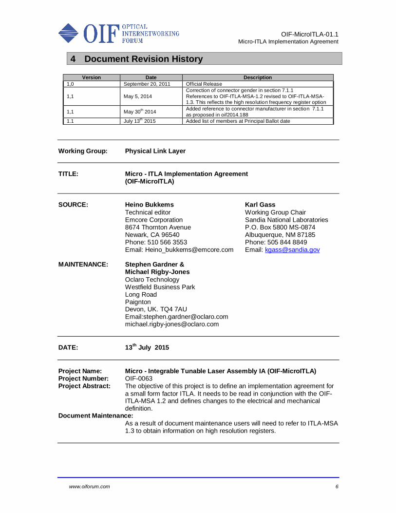
Working Group: Physical Link Layer
TITLE: Micro - ITLA Implementation Agreement (OIF-MicroITLA)
SOURCE: Heino Bukkems Karl Gass
Technical editor Working Group Chair Emcore Corporation Sandia National Laboratories 8674 Thornton Avenue P.O. Box 5800 MS-0874 Newark, CA 96540 Albuquerque, NM 87185 Phone: 510 566 3553 Phone: 505 844 8849 Email: [email protected] Email: [email protected] MAINTENANCE: Stephen Gardner & Michael Rigby-Jones
Oclaro Technology Westfield Business Park Long Road Paignton Devon, UK. TQ4 7AU Email:[email protected] [email protected]
DATE: 13
th July 2015
Project Name: Micro - Integrable Tunable Laser Assembly IA (OIF-MicroITLA) Project Number: OIF-0063 Project Abstract: The objective of this project is to define an implementation agreement for
a small form factor ITLA. It needs to be read in conjunction with the OIF-ITLA-MSA 1.2 and defines changes to the electrical and mechanical definition.
Document Maintenance:
As a result of document maintenance users will need to refer to ITLA-MSA 1.3 to obtain information on high resolution registers.
OIF-MicroITLA-01.1
Micro-ITLA Implementation Agreement
www.oiforum.com 7
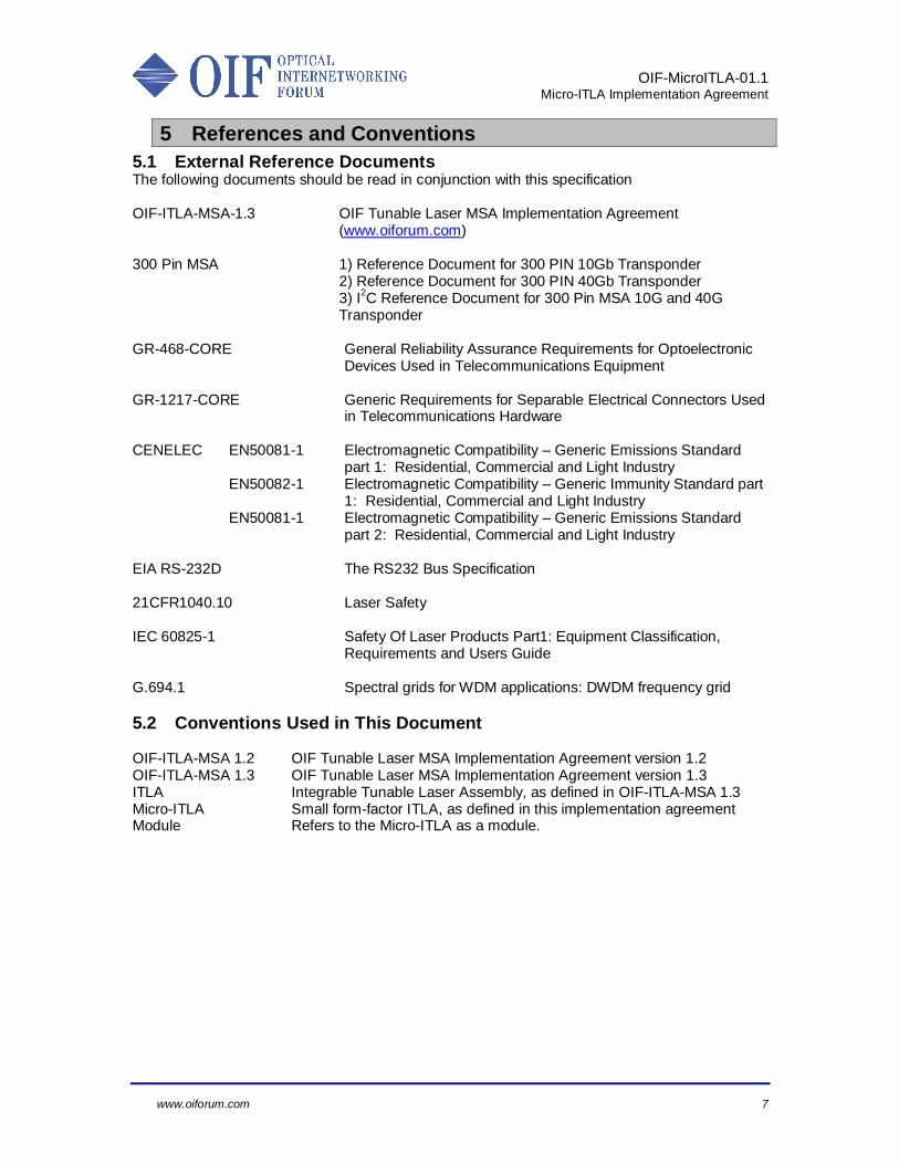
5 References and Conventions
5.1 External Reference Documents The following documents should be read in conjunction with this specification OIF-ITLA-MSA-1.3 OIF Tunable Laser MSA Implementation Agreement
(www.oiforum.com) 300 Pin MSA 1) Reference Document for 300 PIN 10Gb Transponder
2) Reference Document for 300 PIN 40Gb Transponder 3) I
2C Reference Document for 300 Pin MSA 10G and 40G
Transponder GR-468-CORE General Reliability Assurance Requirements for Optoelectronic
Devices Used in Telecommunications Equipment GR-1217-CORE Generic Requirements for Separable Electrical Connectors Used
in Telecommunications Hardware CENELEC EN50081-1 Electromagnetic Compatibility – Generic Emissions Standard
part 1: Residential, Commercial and Light Industry EN50082-1 Electromagnetic Compatibility – Generic Immunity Standard part
1: Residential, Commercial and Light Industry EN50081-1 Electromagnetic Compatibility – Generic Emissions Standard
part 2: Residential, Commercial and Light Industry EIA RS-232D The RS232 Bus Specification 21CFR1040.10 Laser Safety IEC 60825-1 Safety Of Laser Products Part1: Equipment Classification,
Requirements and Users Guide G.694.1 Spectral grids for WDM applications: DWDM frequency grid
5.2 Conventions Used in This Document OIF-ITLA-MSA 1.2 OIF Tunable Laser MSA Implementation Agreement version 1.2 OIF-ITLA-MSA 1.3 OIF Tunable Laser MSA Implementation Agreement version 1.3 ITLA Integrable Tunable Laser Assembly, as defined in OIF-ITLA-MSA 1.3 Micro-ITLA Small form-factor ITLA, as defined in this implementation agreement Module Refers to the Micro-ITLA as a module.

OIF-MicroITLA-01.1
Micro-ITLA Implementation Agreement
www.oiforum.com 8
6 Introduction
This section introduces the Micro-ITLA. The reader should refer back to OIF-ITLA-MSA 1.3 for an overview of the communication and commands (section 6.3 – 6.5).
6.1 Scope
This document describes an additional mechanical form-factor to the Multi-Source Agreement OIF-ITLA-MSA 1.3. Referring back to OIF-ITLA-MSA 1.3 document, this Implementation Agreement only details the electrical and mechanical characteristics for which the Micro-ITLA implementation agreement replaces OIF-ITLA-MSA 1.3.
6.2 Background The OIF has completed three tunable laser projects. The first project resulted in the Tunable Laser Implementation Agreement, OIF-TL-01.1 began in April 2001 and was released in November 2002. A large number of contributors from a wide variety of consumers and suppliers of tunable lasers were involved in contributing and reviewing the first Implementation Agreement. It addressed the communication protocol, electrical interface and mechanical form factor interoperability for tunable continuous wavelength (CW) lasers. The document serves as a roadmap for future tunable device implementation agreements. In February 2003, the OIF began a new fast track project, the Tunable Laser MSA Implementation Agreement. This MSA-IA builds upon the existing Tunable Laser Implementation Agreement, generating a more comprehensive specification of the optical, electrical, mechanical, and communication protocols. It was completed in May 2003. In October 2003, the OIF began a new project #0013, the Integrable Tunable Laser Assembly (ITLA) MSA Implementation Agreement to focus on standardization of a CW laser subassembly for integration into both the 3.5” x 4.5” transponder as well as the small form factor transponder. This Implementation Agreement (OIF-ITLA-MSA1.1) was completed in November 2005. In June 2008 a maintenance update (OIF-ITLA-MSA 1.2) was released.
In July 2010, the OIF initiated project #0063, the Micro Integrable Tunable Laser Assembly (Micro-ITLA) Implementation Agreement to define an alternate smaller form-factor for a module with the performance of an ITLA. The objective was to realize at least a factor two reduction in area and a reduction in height. In addition the power consumption and max case temperature was to be revisited.
The OIF Implementation Agreements can be found at www.oiforum.com The link to these documents is http://www.oiforum.com/documents/implementation-agreements/
OIF-MicroITLA-01.1
Micro-ITLA Implementation Agreement
www.oiforum.com 9
7 Physical Layer & Electrical Characteristics
This section describes the electrical interface and the physical layer interface. The reader should refer back to OIF-ITLA-MSA 1.3 for all specifications that are not specifically included in this document.
7.1 Assembly Electrical Interface
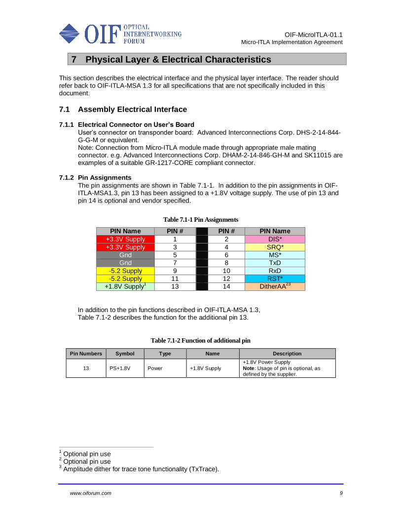
7.1.1 Electrical Connector on User’s Board
User’s connector on transponder board: Advanced Interconnections Corp. DHS-2-14-844-G-G-M or equivalent. Note: Connection from Micro-ITLA module made through appropriate male mating connector. e.g. Advanced Interconnections Corp. DHAM-2-14-846-GH-M and SK11015 are examples of a suitable GR-1217-CORE compliant connector.
7.1.2 Pin Assignments
The pin assignments are shown in Table 7.1-1. In addition to the pin assignments in OIF-ITLA-MSA1.3, pin 13 has been assigned to a +1.8V voltage supply. The use of pin 13 and pin 14 is optional and vendor specified.
Table 7.1-1 Pin Assignments
PIN Name PIN # PIN # PIN Name
+3.3V Supply 1 2 DIS*
+3.3V Supply 3 4 SRQ*
Gnd 5 6 MS*
Gnd 7 8 TxD
-5.2 Supply 9 10 RxD
-5.2 Supply 11 12 RST*
+1.8V Supply1 13 14 DitherAA
23
In addition to the pin functions described in OIF-ITLA-MSA 1.3, Table 7.1-2 describes the function for the additional pin 13.
Table 7.1-2 Function of additional pin
Pin Numbers Symbol Type Name Description
13 PS+1.8V Power +1.8V Supply
+1.8V Power Supply
Note: Usage of pin is optional, as defined by the supplier.
1 Optional pin use
2 Optional pin use
3 Amplitude dither for trace tone functionality (TxTrace).
OIF-MicroITLA-01.1
Micro-ITLA Implementation Agreement
www.oiforum.com 10
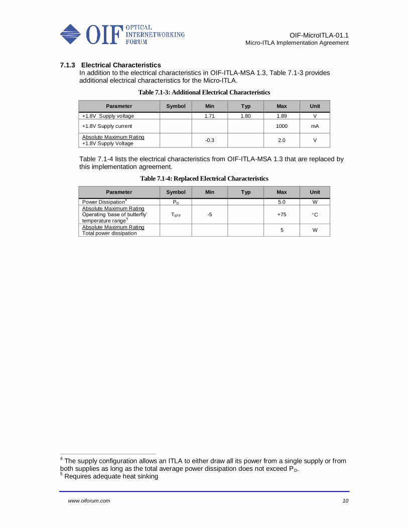
7.1.3 Electrical Characteristics
In addition to the electrical characteristics in OIF-ITLA-MSA 1.3, Table 7.1-3 provides additional electrical characteristics for the Micro-ITLA.
Table 7.1-3: Additional Electrical Characteristics
Parameter Symbol Min Typ Max Unit
+1.8V Supply voltage 1.71 1.80 1.89 V
+1.8V Supply current 1000 mA
Absolute Maximum Rating
+1.8V Supply Voltage -0.3 2.0 V
Table 7.1-4 lists the electrical characteristics from OIF-ITLA-MSA 1.3 that are replaced by this implementation agreement.
Table 7.1-4: Replaced Electrical Characteristics
Parameter Symbol Min Typ Max Unit
Power Dissipation4 PD 5.0 W
Absolute Maximum Rating Operating ‘base of butterfly’
temperature range5
TBTF -5 +75 C
Absolute Maximum Rating Total power dissipation
5 W
4 The supply configuration allows an ITLA to either draw all its power from a single supply or from
both supplies as long as the total average power dissipation does not exceed PD. 5 Requires adequate heat sinking
OIF-MicroITLA-01.1
Micro-ITLA Implementation Agreement
www.oiforum.com 11
8 Transport Layer
The reader should refer back to OIF-ITLA-MSA 1.3 for the definition of the transport layer (section 8).
OIF-MicroITLA-01.1
Micro-ITLA Implementation Agreement
www.oiforum.com 12
9 Command Interface (Application Layer)
The reader should refer back to OIF-ITLA-MSA 1.3 for the definition of the command interface (section 9).
OIF-MicroITLA-01.1
Micro-ITLA Implementation Agreement
www.oiforum.com 13
10 Alarm and Status Register Behavior
The reader should refer back to OIF-ITLA-MSA 1.3 for the definition of the alarm and status register behavior (section 10).
OIF-MicroITLA-01.1
Micro-ITLA Implementation Agreement
www.oiforum.com 14
11 Optical Specifications
The reader should refer back to OIF-ITLA-MSA 1.3 for the optical specifications (section 11).
OIF-MicroITLA-01.1
Micro-ITLA Implementation Agreement
www.oiforum.com 15
12 The Mechanical Specifications This section replaces the mechanical specifications (section 12) in OIF-ITLA-MSA 1.3.
12.1 Micro-ITLA Mechanical Outline Dimensions
Figure 12.1-1 and Table 12.1-1 detail the mechanical outline of the Micro-ITLA. See §7.1.1 for details on the electrical connection. The minimum fiber bend radius is 15 mm. The mounting holes are without thread, suitable for M1.6 screws. Note: the sum of the MAX dimension for L (length of module) and LF (length of fiber boot) exceeds the MAX dimension for LT (total length). The module vendor has the option to trade-off between L and LF, with the condition that MAX dimensions for LT, LF and L are not exceeded.

OIF-MicroITLA-01.1
Micro-ITLA Implementation Agreement
www.oiforum.com 16
Figure 12.1-1 Mechanical Outline Dimensions
Table 12.1-1: Mechanical Outline Dimensions
Parameter Symbol Value
Width of module W 20 mm
Length of module L MIN 34 mm
MAX 45 mm
Total length LT MAX 65 mm
Height of module H MAX 7.5 mm
Pitch of mounting hole – length direction LM 30 mm
Pitch of mounting hole – width direction WM 16 mm
Offset of mounting hole from edge of module OM 2 mm
Diameter mounting hole D 2 mm
Offset centerline connector to mounting hole LC 2 mm
Width fiber boot area WF 14 mm
Length fiber boot area LF MAX 25 mm
Length fiber boot keep out zone LK 10 mm
Clearance below boot HK 1 mm
Length between start of laser hot zone and mounting hole LH 12 mm
Width of laser hot zone WH 14 mm
OIF-MicroITLA-01.1
Micro-ITLA Implementation Agreement
www.oiforum.com 17
13 Appendix A: Open Issues / Current Work Items None
14 Appendix B: List of Companies and Contributors
14.1 Technical Contributors
Ciena Ian Betty CyOptics John Johnson Emcore Genji Tohmon Emcore Heino Bukkems JDSU Andrew Stoddard JDSU Robert Blum Oclaro Jinyu Mo Oclaro Stephen Gardner Oclaro Yi Li Opnext Jon Anderson
OIF-MicroITLA-01.1
Micro-ITLA Implementation Agreement
www.oiforum.com 18
14.2 List of OIF Member Companies (at time of adoption)
Acacia Communications Furukawa Electric Japan Oclaro
ADVA Optical Networking Google Orange
Alcatel-Lucent Hitachi PETRA
Altera Huawei Technologies Co., Ltd. Picometrix
AMCC IBM Corporation PMC Sierra
Amphenol Corp. Infinera QLogic Corporation
Analog Devices Inphi Qorvo
Anritsu Intel Ranovus
Avago Technologies Inc. Ixia Rockley Photonics
Broadcom JDSU Samtec Inc.
Brocade Juniper Networks Semtech
BRPhotonics Kaiam Socionext Inc.
BTI Systems Kandou Spirent Communications
China Telecom KDDI R&D Laboratories Sumitomo Electric Industries
Ciena Corporation Keysight Technologies, Inc. Sumitomo Osaka Cement
Cisco Systems Luxtera TE Connectivity
ClariPhy Communications M/A-COM Technology Solutions Tektronix
Coriant R&G GmbH Marvell Technology TELUS Communications, Inc.
CPqD Mellanox Technologies TeraXion
EMC Corporation Microsemi Inc. Texas Instruments
Emcore Microsoft Corporation Time Warner Cable
Ericsson Mitsubishi Electric Corporation US Conec
ETRI Molex Verizon
FCI USA LLC MoSys, Inc. Xilinx
Fiberhome Technologies Group NEC Yamaichi Electronics Ltd.
Finisar Corporation NeoPhotonics ZTE Corporation
Fujikura NTT Corporation Fujitsu O-Net Communications (HK) Limited

OIF-MicroITLA-01.1
Micro-ITLA Implementation Agreement
www.oiforum.com 19
15 Document Index
A
Absolute Maximum Ratings ..........................................................................................................................16
C
Connector
Electrical ......................................................................................................................................................9
Pin assignments ...........................................................................................................................................9
Conventions .....................................................................................................................................................7
D
Document
Scope ...........................................................................................................................................................8
E
Electrical Characteristics ............................................................................................ 9, 10, See Specifications
M
Mechanical Specifications
Module.......................................................................................................................................................15
P
Physical interfaces ...........................................................................................................................................9
Pin Assignments ..............................................................................................................................................9
R
References .......................................................................................................................................................7


![On an integrable discretisation of the Lotka-Volterra system · all conserved quantities of the integrable system. This problem prompts a concept called integrable discretization[1]](https://img.pdfslide.net/doc/110x75/5f0ea3b77e708231d4403581/on-an-integrable-discretisation-of-the-lotka-volterra-all-conserved-quantities-of.jpg)