Embed Size (px)
Citation preview
Li et al. Light: Science & Applications (2020) 9:84 Official journal of the CIOMP 2047-7538https://doi.org/10.1038/s41377-020-0323-y www.nature.com/lsa
ART ICLE Open Ac ce s s
Micro-rocket robot with all-optic actuatingand tracking in bloodDengfeng Li 1, Chao Liu 1, Yuanyuan Yang1, Lidai Wang 1,2 and Yajing Shen1,2
AbstractMicro/nanorobots have long been expected to reach all parts of the human body through blood vessels for medicaltreatment or surgery. However, in the current stage, it is still challenging to drive a microrobot in viscous media at highspeed and difficult to observe the shape and position of a single microrobot once it enters the bloodstream. Here, wepropose a new micro-rocket robot and an all-optic driving and imaging system that can actuate and track it in bloodwith microscale resolution. To achieve a high driving force, we engineer the microrobot to have a rocket-like triple-tube structure. Owing to the interface design, the 3D-printed micro-rocket can reach a moving speed of 2.8 mm/s (62body lengths per second) under near-infrared light actuation in a blood-mimicking viscous glycerol solution. We alsoshow that the micro-rocket robot is successfully tracked at a 3.2-µm resolution with an optical-resolutionphotoacoustic microscope in blood. This work paves the way for microrobot design, actuation, and tracking in theblood environment, which may broaden the scope of microrobotic applications in the biomedical field.
IntroductionThe development of autonomous artificial micro/
nanorobots has attracted considerable attention due totheir potential in various biomedical applications, such asin vivo treatment or surgery1. In recent years, scientistshave desired that microrobots be able to reach all parts ofthe human body through blood vessels to assess or treatdiseases in different organs2. In the current stage, drugdelivery and tumor treatment relying on microrobots aremostly carried out in the stomach, intestinal tract, orsubcutaneous tissue3–6. To assist robots in entering otherorgans, blood vessels are the best channel, as blood iscirculated throughout the body. For the time being,however, the development of microrobots that can workin the blood faces many challenges, including theachievement of effective actuation and precise
observation, which become more serious for a robot witha size of less than 100 µm.Different from the open environment in a lab, a
microrobot experiences harsh situations in blood, whichis a viscous and fast-flowing environment that can bedifficult to swim through. Although chemical-drivenmicrorobots are capable of high-speed motion, therequired chemical fuels are often toxic; hence, they cannotbe used in blood vessels7. Magnetic field actuation oftenshows good biological compatibility due to its noninvasivepeculiarity and good controllability in viscous liquids8,9.However, the corresponding low peak power and movingspeed prevent its application in blood vessels, even in theslowest capillaries10. Among the nontoxic noninvasivephysical field actuations11,12, light-driven microrobotsoften tend to exhibit high-speed motion, and researchershave proved the powerful capability of light-drivenmicrorobots to penetrate the cell membrane underpulsed light excitation13,14. The flexibility of the modula-tion of the wavelength, frequency, and intensity of lightwill increase the applicability of light-driven microrobots.Moreover, effective light actuation requires only
© The Author(s) 2020OpenAccessThis article is licensedunder aCreativeCommonsAttribution 4.0 International License,whichpermits use, sharing, adaptation, distribution and reproductionin any medium or format, as long as you give appropriate credit to the original author(s) and the source, provide a link to the Creative Commons license, and indicate if
changesweremade. The images or other third partymaterial in this article are included in the article’s Creative Commons license, unless indicated otherwise in a credit line to thematerial. Ifmaterial is not included in the article’s Creative Commons license and your intended use is not permitted by statutory regulation or exceeds the permitted use, you will need to obtainpermission directly from the copyright holder. To view a copy of this license, visit http://creativecommons.org/licenses/by/4.0/.
Correspondence: Lidai Wang ([email protected]) orYajing Shen ([email protected])1Department of Biomedical Engineering, City University of Hong Kong, 999077Hong Kong, China2City University of Hong Kong Shenzhen Research Institute, Shenzhen 518057,ChinaThese authors contributed equally: Dengfeng Li, Chao Liu.
1234
5678
90():,;
1234
5678
90():,;
1234567890():,;
1234
5678
90():,;

asymmetry in the robotic structure or actuation area,offering more flexibility for the structural design ofa robot.In addition to actuation, another challenge is the precise
tracking of a microrobot in the bloodstream15. To date,many imaging techniques, such as X-ray imaging, CTimaging, MR imaging, fluorescence imaging, and ultra-sound imaging, have been tested for microrobot obser-vation in living tissue16. Even though these methods canfind the swarm location of microrobots in living animals,it is still difficult to image and track a single microrobotin vivo with high resolution. As a new imaging method,photoacoustic (PA) tomography has the advantages ofhigh resolution and optical-absorption contrast, and hasdemonstrated its potential for tracking microcapsules fullof spherical microrobots in the mouse intestine or microobjects in ex vivo tissues17–19. However, due to the pooroptical absorption of microrobots and unoptimized ima-ging sensitivity, photoacoustic imaging of a singlemicrorobot has not been implemented in blood. To pre-cisely track the motion of a microrobot in a blood vessel,it is essential to engineer the microrobot and photo-acoustic imaging system such that the imaging sensitivityis improved to a micrometer resolution20.According to nature, the interface plays a crucial role in
reinforcing the interaction efficiency. For instance, lotusesrealize strong buoyancy on the surface of water by largenumbers of micro- and nanoscopic architectures on theirleaf surfaces, which increase the contact area and greatlyincrease the interaction efficiency between the organism
and matter21. The optimized contact interface is expectedto be very beneficial in building up the propulsion effi-ciency of microrobots. Herein, inspired by the interfaceenhancement concept, we design a three-dimensional(3D) structure with multinozzles on a robot to speed upthe light-driven efficiency. The multi-nozzle structureincreases the quantity of the propulsion channel and thelight-excitation area and leads to a threefold speedincrease. In addition to the effective motion in a viscousfluid, this micro-rocket can also be tracked by optical-resolution photoacoustic imaging in blood with a 3.2-µmresolution.
ResultsSystem of photoacoustic imaging for single-microrobottrackingWe develop an optical-resolution photoacoustic
microscopy (OR-PAM) system to track a single micro-robot in the bloodstream (Fig. 1). When a short-pulsedlaser beam irradiates light-absorbing materials, theabsorbed energy will be converted into ultrasonic emis-sion. In the OR-PAM system, a nanosecond pulsed laserbeam (532 nm) is coupled into a 2-m single-mode fiber asthe light source. After the fiber, the laser beam is focusedby an objective lens, is reflected with a prism, and illu-minates the sample to generate the photoacoustic wave.The photoacoustic wave is collected by a concave acousticlens, and detected by a piezoelectric ultrasound transdu-cer. Volumetric images are obtained by raster scanningof the OR-PAM probe. The lateral resolution of this
532-nmpulsed laser
UST
3Dscanner
Mirror
Water
Trigger 1
DAQ
Trigger 3
Amp
Trigger 2
Computer
Blood
Micro-rocket
CW laseractuation
808 nm
Photoacousticemission
Blood vessel model
Collimator
Fibre
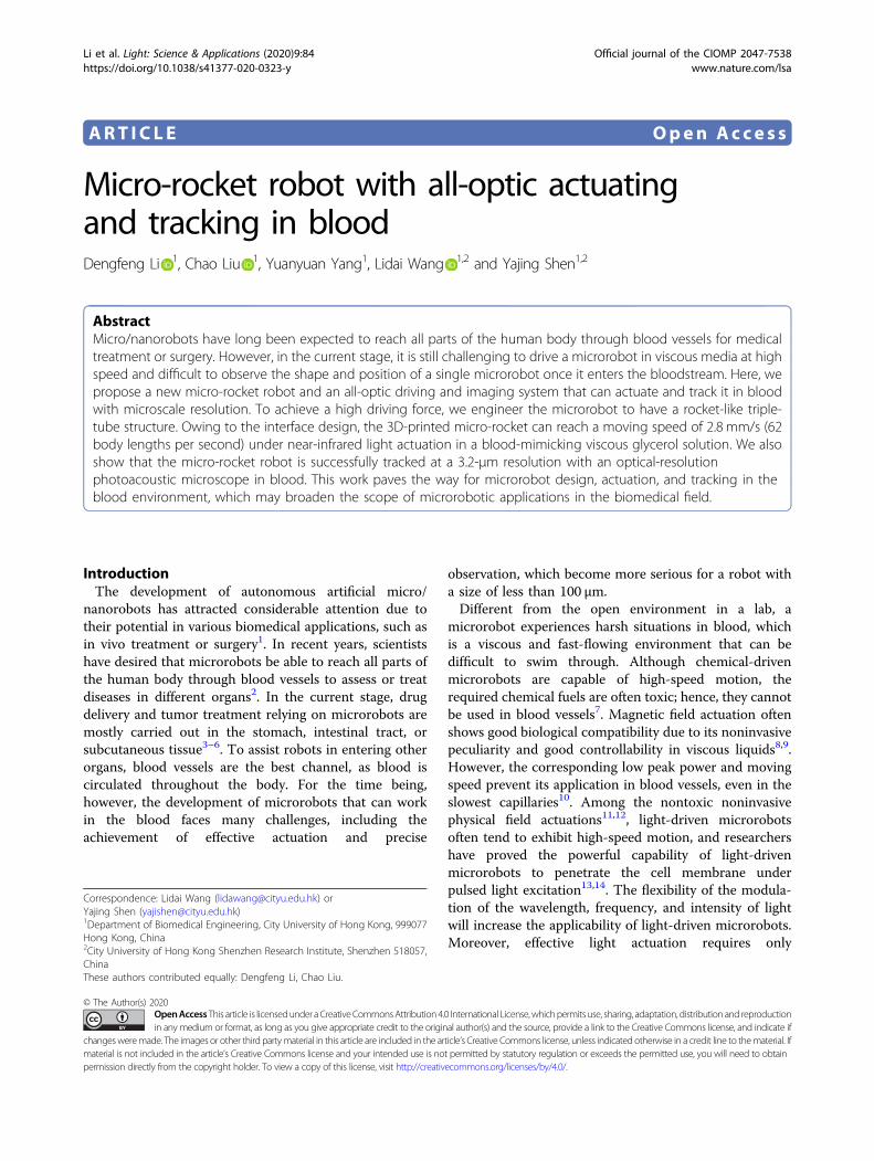
Fig. 1 Schematic illustration of the micro-rocket robot with all-optic actuating and tracking carried out in the blood. The micro-rocket isactuated by a near-infrared continuous wave (CW) laser to realize forward motion in the blood vessel. An 8-kHz 50-nJ pulse laser with a wavelengthof 532 nm is used for photoacoustic imaging. The rocket’s attitude and position can be observed with a lateral resolution of 3.2 µm based on anoptical-resolution photoacoustic system. Amp amplifier, DAQ data acquisition, UST ultrasound transducer
Li et al. Light: Science & Applications (2020) 9:84 Page 2 of 10

OR-PAM system is 3.2 µm (Supplementary Fig. S1). Witha layer of gold coating, the micro-rocket can generatestronger photoacoustic signals than the blood at 532 nm,which guarantees the imaging contrast of the micro-rocket in the blood. Under the illumination of a quasi-CW808-nm laser, the micro-rocket can realize fast motion ina rubber vessel simulating the vascular scene. At the sametime, the OR-PAM system provides high-resolutiontracking of the micro-rocket.
Micro-rocket with multinozzlesTo effectively move in highly viscous blood, the robot
needs to generate a high instantaneous propelling force.Inspired by the interface enhancement, a rocket-shapedstructure with three nozzles at one end is designed. Themicroscale rocket is fabricated by 3D printing (Fig. 2a).This direct laser writing technique can achieve nanoscaleresolution, making it suitable for fabricating 3D hollowmicrostructures. On a transparent glass substrate, SU-8 isprinted with 400-nm slicing and 400-nm filling (Supple-mentary Fig. S2), and the cross-linked structures stand asan array (Fig. 2b) after 3D printing and development. Themicrostructure is composed of three tubes with a
diameter of 20 µm and a wall thickness of 2 µm. Thelengths of the central tube and two symmetrical tubes are45 µm and 22.5 µm, respectively (Supplementary Fig. S3).To enhance the driving force and photoacoustic ima-
ging sensitivity, a 100-nm-thick gold layer is coated ontothe microrobots. Figure 2c demonstrates the uniform goldcoating via energy dispersive X-ray spectrum (EDS)mapping as viewed from the top and side of the micro-rocket. The functional layer on the surface of the micro-rocket, i.e., the gold layer, exhibits strong absorption inthe visible and near-infrared bands (Supplementary Fig.S6), and thus generates strong thermal energy that drivesthe micro-rocket forward upon quasi-CW 808-nm irra-diation. In imaging, it also generates strong photoacousticsignals upon nanosecond 532-nm optical excitation.
Light actuation mechanism of the microrobot withmultiple nozzlesThe micro-rocket is actuated based on the photo-
thermal mechanism. Under the excitation of a 1-W 808-nm laser with an ~354-µm focus size (Supplementary Fig.S8), photothermal heat is generated from the Au layer onthe microrobots. When the near-infrared laser excites the
50 μm
25 μm
cb
a
Au
Au
Structure design
Metal coating
Direct laser writingSpin coating
DevelopmentMicro-manipulationLight-driven motion
SU-8Glass substrate
Near-IR pulse laser
Micro-rocketsAu
Glass needleLaserGlycerol
Fig. 2 Design and fabrication of interface-enhanced micro-rockets by 3D printing. a Schematic of the 3D microprinting process. Direct laserwriting for 3D microprinting with a nanoscale resolution; the 3D structures are acquired after developing the uncross-linked SU-8 photoresist; a goldlayer with a thickness of 100 nm is coated onto the micro-rocket; and the micro-rockets are transferred via micro-manipulation to the liquid solutionfor further light-driven motion. b SEM images of the micro-rocket array. Inspired by the interface enhancement in nature, the micro-rocket isdesigned with three tubes with a diameter of 20 µm and a wall thickness of 2 µm. The lengths of the central tube and two symmetrical tubes are45 µm and 22.5 µm, respectively. c The top view and side view of the energy dispersive X-ray spectrum (EDS) mapping of the micro-rockets
Li et al. Light: Science & Applications (2020) 9:84 Page 3 of 10
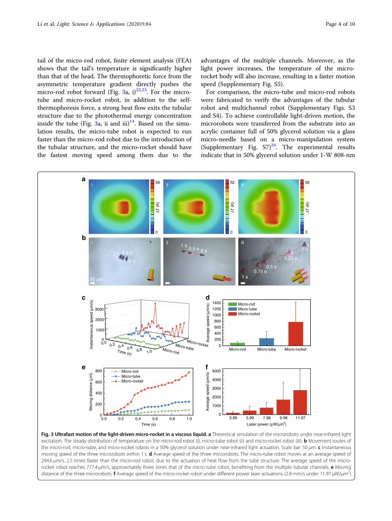
tail of the micro-rod robot, finite element analysis (FEA)shows that the tail’s temperature is significantly higherthan that of the head. The thermophoretic force from theasymmetric temperature gradient directly pushes themicro-rod robot forward (Fig. 3a, i)22,23. For the micro-tube and micro-rocket robot, in addition to the self-thermophoresis force, a strong heat flow exits the tubularstructure due to the photothermal energy concentrationinside the tube (Fig. 3a, ii and iii)14. Based on the simu-lation results, the micro-tube robot is expected to runfaster than the micro-rod robot due to the introduction ofthe tubular structure, and the micro-rocket should havethe fastest moving speed among them due to the
advantages of the multiple channels. Moreover, as thelight power increases, the temperature of the micro-rocket body will also increase, resulting in a faster motionspeed (Supplementary Fig. S5).For comparison, the micro-tube and micro-rod robots
were fabricated to verify the advantages of the tubularrobot and multichannel robot (Supplementary Figs. S3and S4). To achieve controllable light-driven motion, themicrorobots were transferred from the substrate into anacrylic container full of 50% glycerol solution via a glassmicro-needle based on a micro-manipulation system(Supplementary Fig. S7)24. The experimental resultsindicate that in 50% glycerol solution under 1-W 808-nm
b
a
0
200
400
600
800
1000
1200
1400
Micro-tubeMicro-rod Micro-rocket
Micro-rodMicro-tubeMicro-rocket
Ave
rage
spe
ed (
μm/s
)
3.99 5.99 7.98 9.98 11.970
1000
2000
3000
4000
5000
Ave
rage
spe
ed (
μm/s
)
Laser power (μW/μm2)0.0 0.2 0.4 0.6 0.8 1.0
0
200
400
600
800 Micro-rodMicro-tubeMicro-rocket
Mov
ing
dist
ance
(μm
)
Time (s)
c
e
d
f
92
ΔT (
K)
ii iiii
ii iiii
1 s
0 s
0.5 s 0 s 0 s0.5 s1 s
0.5 s
1 s0.75 s
0.25 s
0.00.2 0.4
0.60.8
1.0
0
1000
2000
3000
Inst
anta
neou
s sp
eed
(μm
/s)
Time (s)Micro-rod
Micro-tube
Micro-rocket
50 μm
0
52
ΔT (
K)
0
58
ΔT (
K)
0
Fig. 3 Ultrafast motion of the light-driven micro-rocket in a viscous liquid. a Theoretical simulation of the microrobots under near-infrared lightexcitation. The steady distribution of temperature on the micro-rod robot (i), micro-tube robot (ii) and micro-rocket robot (iii). b Movement routes ofthe micro-rod, micro-tube, and micro-rocket robots in a 50% glycerol solution under near-infrared light actuation. Scale bar: 50 µm. c Instantaneousmoving speed of the three microrobots within 1 s. d Average speed of the three microrobots. The micro-tube robot moves at an average speed of244.6 µm/s, 2.5 times faster than the micro-rod robot, due to the actuation of heat flow from the tube structure. The average speed of the micro-rocket robot reaches 777.4 µm/s, approximately three times that of the micro-tube robot, benefiting from the multiple tubular channels. e Movingdistance of the three microrobots. f Average speed of the micro-rocket robot under different power laser actuations (2.8 mm/s under 11.97 µW/µm2)
Li et al. Light: Science & Applications (2020) 9:84 Page 4 of 10

laser irradiation with a power density of 7.98 µW/µm2, themicro-rocket travels 777.4 µm within 1 s, being approxi-mately threefold faster than the micro-tube robot and 7.5times faster than the micro-rod robot, benefiting from themultiple tubular channels (Fig. 3d, e; SupplementaryMovie S1). These results agree well with the theoreticalprediction.
High-speed motion in a highly viscous solutionThe viscous liquid, i.e., 50% glycerol solution, is used to
imitate the high-viscosity environment in the humanbody. The viscosity of the 50% glycerol solution is4.21 mPa‧s, which is very close to that of human blood(3–4mPa‧s). In this viscous liquid, it is impressive that theinstantaneous moving speed of the micro-rocket exceeds3 mm/s under 1-W 808-nm laser actuation (Fig. 3c), beingmuch faster than the micro-rod and micro-tube robotsowing to the enhanced interface design with multiplenozzles. This energetic instantaneous power allows themicro-rocket to break through the viscous force of theviscous fluid. Moreover, the micro-rocket presents ahigher moving speed as the actuated laser power increases
(Fig. 3f; Supplementary Movie S2). Specifically, under theexcitation of the 1.5-W laser, the average moving speedreaches a fairly impressive 2.8 mm/s (62 body lengthsper second), which serves as the baseline speed for rocketusage in the human body. Compared with the micro-robots actuated by other methods, our design exhibitsobvious advances in the motion speed (SupplementaryTable S1), especially in instant power generation, offeringthe basis for the possible effective motion in real bodyfluids.The swimming direction of the micro-rocket is adjusted
by the laser excitation position in a controllable manner.When the laser irradiates the whole tail of the micro-rocket, the rocket moves in a straight line (Fig. 3b). Whenthe laser beam irradiates only one side of the rocket’s heador tail, the asymmetric heat flow between the two sideswill cause rotation of the rocket body (Fig. 4a). Then, themicro-rocket can run along a straight line again byredirecting the irradiation area of the laser to once againcover the rocket’s tail. Figure 4a, b shows that the micro-rocket realizes 152° turning within 1.1 s (SupplementaryMovie S3). This controlled movement, to a large extent,
0 1 2 3 4 5 6 7 8 9 10 1130
60
90
120
150
180
210
240
Ang
le (
°)
Time (s)
1.1 s
b
d
0 s3.6 s
3.1 s
3 s
1.5 s0.8 s0.6 s4 s
a
0.0 s5.5 s
6.0 s
6.3 s
6.8 s
9.6 s
10.4 s
50 μm
c
50% glycerol
Micro-rocket in the microtube
Micro-rocket
100 μm
5.5 s
6.6 s152°
0
1000
2000
3000
0 1 2 3 40
300
600
900
Dis
tanc
e (μ
m)
Time (s)
Spe
ed (
μm/s
)
152°
Heat
5.5 sRotation
Irradiation area
Force
Fig. 4 Motion control of the rocket robot in free space and fast actuation in a blood-vessel-like microtube. a The turning motion of themicro-rocket in 50% glycerol in free space controlled by near-infrared light. The light excites the side face of the micro-rocket to achieve the turningmovement. b The relationship between the micro-rocket moving angle and the moving time. Turning of more than 150° is realized within 1.1 s.c Fast motion of the micro-rocket in the microtube. A microtube filled with a 50% glycerol solution was used to simulate a blood vessel.d Instantaneous moving speed and moving distance of the micro-rocket in the microtube
Li et al. Light: Science & Applications (2020) 9:84 Page 5 of 10
improves the applicability of the micro-rocket, whichprovides the possibility of targeted biomedical treatment.To simulate the micro-rocket’s motion in a static blood
vessel, a rubber microtube with an inner diameter of250 µm full of 50% glycerol is used as the container(Fig. 4c). The micro-rockets are first transferred to theentrance of an empty clean rubber tube by the micro-manipulated glass needle, and then a drop of dilute gly-cerol solution is dripped onto the tube opening to bringthe micro-rockets into the rubber tube based on thecapillary effect. Under the microscope, the controlled 808-nm beam easily reaches the micro-rocket through thetransparent tube. In the rubber tube, the micro-rocketmoves rapidly at an average moving speed of 225.3 µm/sand a maximum instantaneous speed of 3.4 mm/s (Fig. 4d;Supplementary Movie S4). As far as we know, this is thehighest recorded speed of the ~50-µm microrobot in sucha viscous liquid tube. The ability to generate highinstantaneous power allows the micro-rocket to movefreely in the viscous fluid.The inner surface of the lumen of a human body vessel
is generally highly lubricated. Only when the vessel isdiseased, such as the case of arteriosclerosis, may theinternal lubricity of blood vessels change. Therefore, whathinders the motion of the robot is the fast blood flow andhigh blood viscosity instead of the friction or adhesionfrom the vascular inner wall. More importantly, the dis-tribution of the blood flow in blood vessels is parabolic.The closer to the middle of the vessel, the faster the bloodflow is. It may be a good idea to constrain the microrobotnear the surface of the vessel by an additional force, suchas magnetic attraction, to move against the blood flow.
Photoacoustic tracking of a single micro-rocketWe employed OR-PAM to image the micro-rocket in
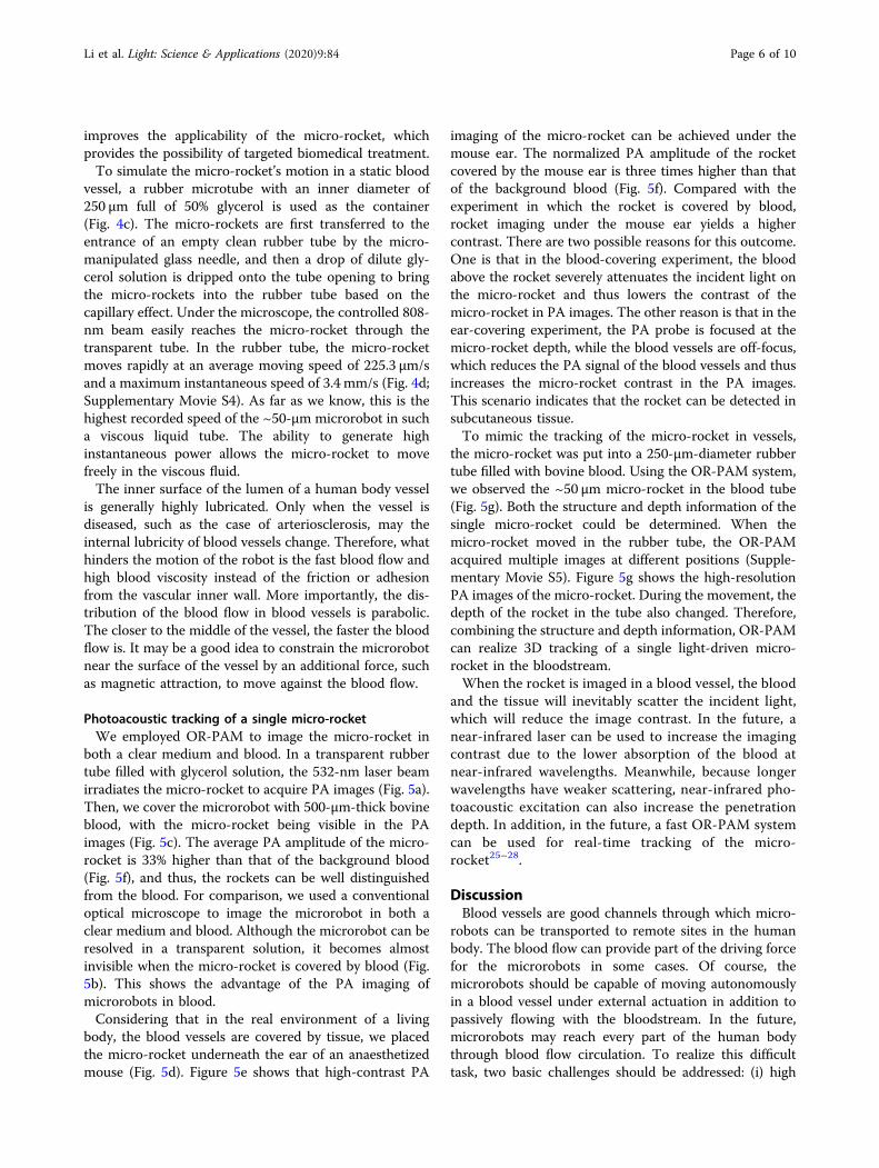
both a clear medium and blood. In a transparent rubbertube filled with glycerol solution, the 532-nm laser beamirradiates the micro-rocket to acquire PA images (Fig. 5a).Then, we cover the microrobot with 500-μm-thick bovineblood, with the micro-rocket being visible in the PAimages (Fig. 5c). The average PA amplitude of the micro-rocket is 33% higher than that of the background blood(Fig. 5f), and thus, the rockets can be well distinguishedfrom the blood. For comparison, we used a conventionaloptical microscope to image the microrobot in both aclear medium and blood. Although the microrobot can beresolved in a transparent solution, it becomes almostinvisible when the micro-rocket is covered by blood (Fig.5b). This shows the advantage of the PA imaging ofmicrorobots in blood.Considering that in the real environment of a living
body, the blood vessels are covered by tissue, we placedthe micro-rocket underneath the ear of an anaesthetizedmouse (Fig. 5d). Figure 5e shows that high-contrast PA
imaging of the micro-rocket can be achieved under themouse ear. The normalized PA amplitude of the rocketcovered by the mouse ear is three times higher than thatof the background blood (Fig. 5f). Compared with theexperiment in which the rocket is covered by blood,rocket imaging under the mouse ear yields a highercontrast. There are two possible reasons for this outcome.One is that in the blood-covering experiment, the bloodabove the rocket severely attenuates the incident light onthe micro-rocket and thus lowers the contrast of themicro-rocket in PA images. The other reason is that in theear-covering experiment, the PA probe is focused at themicro-rocket depth, while the blood vessels are off-focus,which reduces the PA signal of the blood vessels and thusincreases the micro-rocket contrast in the PA images.This scenario indicates that the rocket can be detected insubcutaneous tissue.To mimic the tracking of the micro-rocket in vessels,
the micro-rocket was put into a 250-µm-diameter rubbertube filled with bovine blood. Using the OR-PAM system,we observed the ~50 µm micro-rocket in the blood tube(Fig. 5g). Both the structure and depth information of thesingle micro-rocket could be determined. When themicro-rocket moved in the rubber tube, the OR-PAMacquired multiple images at different positions (Supple-mentary Movie S5). Figure 5g shows the high-resolutionPA images of the micro-rocket. During the movement, thedepth of the rocket in the tube also changed. Therefore,combining the structure and depth information, OR-PAMcan realize 3D tracking of a single light-driven micro-rocket in the bloodstream.When the rocket is imaged in a blood vessel, the blood
and the tissue will inevitably scatter the incident light,which will reduce the image contrast. In the future, anear-infrared laser can be used to increase the imagingcontrast due to the lower absorption of the blood atnear-infrared wavelengths. Meanwhile, because longerwavelengths have weaker scattering, near-infrared pho-toacoustic excitation can also increase the penetrationdepth. In addition, in the future, a fast OR-PAM systemcan be used for real-time tracking of the micro-rocket25–28.
DiscussionBlood vessels are good channels through which micro-
robots can be transported to remote sites in the humanbody. The blood flow can provide part of the driving forcefor the microrobots in some cases. Of course, themicrorobots should be capable of moving autonomouslyin a blood vessel under external actuation in addition topassively flowing with the bloodstream. In the future,microrobots may reach every part of the human bodythrough blood flow circulation. To realize this difficulttask, two basic challenges should be addressed: (i) high
Li et al. Light: Science & Applications (2020) 9:84 Page 6 of 10

moving speed to overcome viscous fluid resistance and(ii) high-resolution imaging to observe a single micro-robot in blood or tissue.With high instantaneous driving energy, light actuation
is an ideal choice for biomedical microrobot design. Here,a 3D-printed tubular micro-rocket is developed as amicrorobot capable of moving quickly in a viscous fluid.The Au layer was used as the light-absorption layer foractuation and photoacoustic tracking. Generally, tubularmicrorobots often achieve a high moving speed in a liquid.Inspired by the important role of the surface interface innature, we designed a microrobot with rocket-like mul-tinozzles. Consequently, the moving speed of the micro-rocket could reach 2.8 mm/s in viscous 50% glycerol
solution with a similar viscosity to that of human blood.Moreover, light excitation enabled the micro-rocket tobreak away from the rubber tube wall and realize effectivemotion in this blood vessel model. The high-performancemotion of the light-driven micro-rocket in viscous fluidopens the door for its future biomedical applications inthe human body.With a high resolution of several micrometers, OR-
PAM can observe a single micro-rocket in the blood-stream. To simulate the biological environment, a seriesof experiments under different imaging conditions werecarried out. First, immersed in blood, the positions ofseveral micro-rockets could be recognized by the sig-nificantly comparable photoacoustic signal between the
a
c
f g
d e
b
100 μm
Fig. 5 Photoacoustic imaging of a single micro-rocket in blood, and penetration of living mouse ear. a Clear high-resolution PA imaging of asingle micro-rocket in the transparent solution. b Optical microscopy of the micro-rockets without blood and within blood. The optical microscopefails to observe the micro-rockets covered by 500-µm-thick bovine blood. c Corresponding visible PA images of these micro-rockets in thick blood.d Mouse ear covering a micro-rocket. e PA imaging of the micro-rocket through the living mouse ear. f Contrast of the normalized PA amplitudebetween the micro-rockets and the blood or the living blood vessel. g High-resolution PA tracking of a single micro-rocket in the blood vessel model,i.e., a 250-µm-diameter rubber tube filled with bovine blood. (Left) PA imaging with the intensity distribution. (Right) PA imaging with the depthdistribution. Combining the structure and depth information, 3D tracking of a single light-driven micro-rocket is realized in the bloodstream. Scalebar: 100 µm for a, b, c, e, and g
Li et al. Light: Science & Applications (2020) 9:84 Page 7 of 10

micro-rockets and the blood. Then, through a livingmouse ear, the micro-rocket still presented an obviousoutline via the photoacoustic imaging method. Finally, arubber tube full of bovine blood was used to model ablood vessel. Under near-infrared light actuation, thesingle micro-rocket could realize effective motion, andclear photoacoustic tracking of the robot could beachieved in the blood vessel model. As a result, optical-resolution photoacoustic imaging provides a new high-resolution biomedical imaging method for microrobotobservation.Although the developed OR-PAM can achieve high-
resolution imaging of a microrobot in blood or under-neath tissue, it is worth noting that the current systemworks only for shallow tissue, i.e., <~1mm. In clinical-oriented applications, two methods might be used in thefuture to increase the penetration depth of OR-PAM. Oneis to use infrared light in the process of photoacousticexcitation. The other method is to use photoacousticendoscopy to image microrobots in deep tissues29–31.Taking advantage of scalable resolutions and depths,photoacoustic imaging of the micro-rocket robot in deeptissue may also be possible in the future using a photo-acoustic computed tomographic system32. In addition,please note that real-time tracking with high resolutionremains difficult to achieve by the current system due toits slow imaging speed, which can be improved bydeveloping faster pulsed lasers and OR-PAM scan-ners26,27. In addition, the intensity of the actuation laserexceeds the safety threshold for in vivo applications,which is an open problem for light-driven microrobots.Therefore, we use a structural design to accelerate therobot and make it able to achieve fast motion under weakdriving light. As future work, more efforts should becarried out in regard to real-time optical-resolutionphotoacoustic microscopy and the fast light actuation ofmicrorobots within the threshold range.There are still some challenges to applying the proposed
device in preclinical or clinical practice. First, biologicaltissue scatters light, which limits the depth of micro-robotic driving and imaging. In the future, other techni-ques, such as mini-invasive laparoscopy or endoscopy,need to be developed to deliver light beyond superficialtissue33. Second, local thermal damage is inevitable due tophotothermal driving. How to avoid or reduce local tissuedamage needs to be studied in the future. For instance,delivering light using an optical fiber or an endoscopicdevice may reduce the optical pathlength in tissue andlower the possibility of tissue damage. Another possibleapproach that can be explored in the future is to cool thetissue before heating so that the thermal damage to thetissue can be mitigated34. Finally, although the micro-rocket can move through trunk blood vessels, it is toolarge to pass through arterioles and capillaries. To avoid
clogging these vessels, two approaches can be explored inthe future. One is to use biodegradable materials to fab-ricate the microrobots. When a robot reaches a smallvessel, it can undergo a certain amount of degradation fora period of time. The other is to reduce the robot sizesuch that it is smaller than the capillary diameter.Although medical micro/nanorobots have achieved
considerable advances, many aspects of research are stillneeded for safe and reliable micro/nanorobot-assistedclinical therapeutics in the human body. Future advancesin materials science in terms of biocompatibility andbiodegradability would intuitively improve the safety ofthe robot itself in the human body35–37. A sophisticatedintegrated system or platform for in vivo robot actuation,control, and medical imaging is also in high demand forreal-world clinical-level applications. Importantly, giventhe extreme complexity of the human environment,determining how a robot can cross biological barriers toreach a diseased site will be a key challenge to overcome37.In conclusion, we developed a 3D-printed ultrafast
micro-rocket and realized effective motion and high-resolution photoacoustic tracking in viscous blood. Underthe actuation of near-infrared light, the high-speedmotion (2.8 mm/s) and powerful energy of the micro-rocket increase the possibility for microrobot applicationsin harsh environments in vivo. More importantly, OR-PAM successfully realizes the clear tracking and obser-vation of a single micro-rocket in a blood vessel with aresolution of 3.2 µm. This work greatly improves thepossibility of biomedical applications of microrobots inthe human body.
Materials and methods3D printing of micro-rocketsThe 3D micro-rocket was printed based on the direct
laser writing technique by the Photonic Professional GTsystem (Nanoscribe GmbH). With a spin-coated 50-μm-thick photoresist (SU-8 50, MicroChem Corp.) on trans-parent glass and utilization of the pre-bake and soft-bakeprocesses, a 780-nm laser was focused in the photoresist,and the structure was printed with 0.4-μm slicing and 0.4-μm filling. After the microprinting and post-bake pro-cesses, the sample was developed in an SU-8 developer(MicroChem Corp.) and rinsed with isopropyl alcohol.After air drying, hundreds of micro-rockets were obtainedfrom the substrate. To realize near-infrared light actua-tion, a 100-nm-thick gold layer was coated on the micro-rocket surface.
CharacterizationThe microstructures of the 3D-printed micro-rockets
were observed by using a field scanning electron micro-scope (FSEM, FEI Quanta 450). The micro-rockets weretransferred to a new clean substrate for the element
Li et al. Light: Science & Applications (2020) 9:84 Page 8 of 10
distribution test. A scanning electron microscope (JEOL/JSM-5600) with an energy dispersive X-ray spectrum(OXFORD #INCA Energy 200 system-IE200C) was usedfor element mapping.
FEA of light-driven micro-rocketFinite element analysis (FEA) was used to analyze the
temperature distribution of the micro-rocket under near-infrared light irradiation. The thermal conductivity, spe-cific heat capacity, and density of the gold (Au) coatingwere 315W/(m‧K), 0.13 kJ/(kg K), and 19300 kg/m3,respectively, and those for SU-8 were 0.2W/(m‧K), 1.5 kJ/(kg K), and 1190 kg/m3. The laser with a power of7.98 μW/μm2 was used to irradiate a quarter of themicrorobot body in the tail region. The radiation time wasset as 0.1 s.
Light actuationThe 3D-printed micro-rockets were transferred to an
acrylic-based container or a microtube full of glycerolsolution by the micro-manipulation system. Glycerol(50%) was used as the viscous fluid medium to imitate thehigh-viscosity environment in the human body. A near-infrared laser with a wavelength of 808 nm was used as thelight source to actuate the micro-rocket.
Optical-resolution photoacoustic microscopyA pulsed laser (VPFL-G-20, Spectra-Physics; operating
wavelength: 532 nm; pulse duration: 7 ns; pulse-repetitionrate: 1 MHz) was used as the light source. The laser wassent to an ultrasonically and optically confocal OR-PAMprobe through a 2-m single-mode fiber (P1-460B-FC-2,Thorlabs Inc). In the OR-PAM probe, the beam wasfocused onto the biological tissue to generate the photo-acoustic signals. In the experiments, a water tank full ofdeionized water was placed on top of the samples to carryout the lossless propagation of the ultrasonic waves con-sidering that the impendence of water is similar to that ofbody tissue. A 50-MHz (V214-BC-RM, Olympus) ultra-sound transducer inside the probe was placed ultra-sonically and optically confocal above the laser beam toacquire the optimized PA signal. Detailed information onthe OR-PAM probe can be found in previous papers25,38–40.A 2D photoacoustic image could be acquired after com-bining with a motorized two-dimensional scanner.
AcknowledgementsThis work is supported by the National Natural Science Foundation of China(61922093, 81627805, 61805102); Research Grants Council of the Hong KongSpecial Administrative Region (21205016, 11215817, 11101618); and ScienceTechnology and Innovation Commission of Shenzhen Municipality, China(JCYJ20170413140519030).
Author contributionsD.L. fabricated the micro-rocket robot and conducted the experiment. C.L.scanned and processed the photoacoustic images. Y.Y. provided assistance
during the experiment and helped with the schematic illustrations. L.W.developed the photoacoustic imaging system and led the imaging portions ofthe project. Y.S. initialized the idea of the robot design and coordinated theproject. All authors wrote and reviewed the paper.
Conflict of interestThe authors declare that they have no conflict of interest.
Supplementary information is available for this paper at https://doi.org/10.1038/s41377-020-0323-y.
Received: 19 January 2020 Revised: 21 April 2020 Accepted: 24 April 2020
References1. Li, J. X. et al. Micro/nanorobots for biomedicine: delivery, surgery, sensing, and
detoxification. Sci. Robot. 2, eaam6431 (2017).2. Kim, Y. et al. Ferromagnetic soft continuum robots. Sci. Robot. 4, eaax7329
(2019).3. Gao, W. et al. Artificial micromotors in the mouse’s stomach: a step toward
in vivo use of synthetic motors. ACS Nano 9, 117–123 (2015).4. De Ávila, B. E. F. et al. Micromotor-enabled active drug delivery for in vivo
treatment of stomach infection. Nat. Commun. 8, 272 (2017).5. Li, J. Y. et al. Development of a magnetic microrobot for carrying and deli-
vering targeted cells. Sci. Robot. 3, eaat8829 (2018).6. Yan, X. H. et al. Multifunctional biohybrid magnetite microrobots for imaging-
guided therapy. Sci. Robot. 2, eaaq1155 (2017).7. Jurado-Sánchez, B., Wang, J. & Escarpa, A. Ultrafast nanocrystals decorated
micromotors for on-site dynamic chemical processes. ACS Appl. Mater. Inter-faces 8, 19618–19625 (2016).
8. Tottori, S. et al. Magnetic helical micromachines: fabrication, controlledswimming, and cargo transport. Adv. Mater. 24, 811–816 (2012).
9. Gao, W. et al. Bioinspired helical microswimmers based on vascular plants.Nano Lett. 14, 305–310 (2014).
10. Ivanov, K. P., Kalinina, M. K. & Levkovich, Y. I. Blood flow velocity in capillaries ofbrain and muscles and its physiological significance. Microvascular Res. 22,143–155 (1981).
11. Tu, Y. F., Peng, F. & Wilson, D. A. Motion manipulation of micro- and nano-motors. Adv. Mater. 29, 1701970 (2017).
12. Chen, X. Z. et al. Small-scale machines driven by external power sources. Adv.Mater. 30, 1705061 (2018).
13. De Ávila, B. E. F. et al. Micromotors go in vivo: from test tubes to live animals.Adv. Funct. Mater. 28, 1705640 (2018).
14. Wu, Z. G. et al. Superfast near-infrared light-driven polymer multilayer rockets.Small 12, 577–582 (2016).
15. Medina-Sánchez, M. & Schmidt, O. G. Medical microbots need better imagingand control. Nature 545, 406–408 (2017).
16. Pané, S. et al. Imaging technologies for biomedical micro- and nanoswim-mers. Adv. Mater. Technol. 4, 1800575 (2019).
17. Wu, Z. G. et al. A microrobotic system guided by photoacoustic computedtomography for targeted navigation in intestines in vivo. Sci. Robot. 4,eaax0613 (2019).
18. Li, L. et al. Single-impulse panoramic photoacoustic computed tomography ofsmall-animal whole-body dynamics at high spatiotemporal resolution. Nat.Biomed. Eng. 1, 0071 (2017).
19. Aziz, A. et al. Real-time optoacoustic tracking of single moving micro-objectsin deep phantom and ex vivo tissues. Nano Lett. 19, 6612–6620 (2019).
20. Wang, L. V. & Yao, J. J. A practical guide to photoacoustic tomography in thelife sciences. Nat. Methods 13, 627–638 (2016).
21. Zhang, J. H. et al. How does the leaf margin make the lotus surface dry as thelotus leaf floats on water. Soft Matter 4, 2232–2237 (2008).
22. Jiang, H. R., Yoshinaga, N. & Sano, M. Active motion of a Janus particle byself-thermophoresis in a defocused laser beam. Phys. Rev. Lett. 105, 268302(2010).
23. Wu, Y. J. et al. Near-infrared light-driven Janus capsule motors: fabrication,propulsion, and simulation. Nano Res. 9, 3747–3756 (2016).
24. Li, D. F. et al. In situ bending and recovery characterization of hollow glassnanoneedle based on nanorobotic manipulation. J. Micromech. Microeng. 27,095011 (2017).
Li et al. Light: Science & Applications (2020) 9:84 Page 9 of 10

25. Wang, L. D. et al. Fast voice-coil scanning optical-resolution photoacousticmicroscopy. Opt. Lett. 36, 139–141 (2011).
26. Liang, Y. Z. et al. Fast-scanning photoacoustic microscopy with a side-looking fiber optic ultrasound sensor. Biomed. Opt. Express 9, 5809–5816(2018).
27. Lan, B. X. et al. High-speed widefield photoacoustic microscopy of small-animal hemodynamics. Biomed. Opt. Express 9, 4689–4701 (2018).
28. Yao, J. J. et al. High-speed label-free functional photoacoustic microscopy ofmouse brain in action. Nat. Methods 12, 407–410 (2015).
29. Yang, J. M. et al. Optical-resolution photoacoustic endomicroscopy in vivo.Biomed. Opt. Express 6, 918–932 (2015).
30. Li, Y. et al. In vivo photoacoustic/ultrasonic dual-modality endoscopy with aminiaturized full field-of-view catheter. J. Biophotonics 11, e201800034 (2018).
31. Lei, P. et al. Ultrafine intravascular photoacoustic endoscope with a 0.7 mmdiameter probe. Opt. Lett. 44, 5406–5409 (2019).
32. Zhang, P. F. et al. In vivo superresolution photoacoustic computedtomography by localization of single dyed droplets. Light.: Sci. Appl. 8, 36(2019).
33. Yun, S. H. & Kwok, S. J. J. Light in diagnosis, therapy and surgery. Nat. Biomed.Eng. 1, 0008 (2017).
34. Das, A., Sarda, A. & De, A. Cooling devices in laser therapy. J. Cutan. AestheticSurg. 9, 215–219 (2016).
35. Nelson, B. J., Kaliakatsos, I. K. & Abbott, J. J. Microrobots for minimally invasivemedicine. Annu. Rev. Biomed. Eng. 12, 55–85 (2010).
36. Soto, F. & Chrostowski, R. Frontiers of medical micro/nanorobotics: in vivoapplications and commercialization perspectives toward clinical uses. Front.Bioeng. Biotechnol. 6, 170 (2018).
37. Ceylan, H. et al. Translational prospects of untethered medical microrobots.Prog. Biomed. Eng. 1, 012002 (2019).
38. Wang, L. D., Maslov, K. & Wang, L. V. Single-cell label-free photoacousticflowoxigraphy in vivo. Proc. Natl Acad. Sci. USA 110, 5759–5764 (2013).
39. Liang, Y. Z. et al. 2 MHz multi-wavelength pulsed laser for functional photo-acoustic microscopy. Opt. Lett. 42, 1452–1455 (2017).
40. Liu, C., Liang, Y. Z. & Wang, L. D. Optical-resolution photoacoustic microscopyof oxygen saturation with nonlinear compensation. Biomed. Opt. Express 10,3061–3069 (2019).
Li et al. Light: Science & Applications (2020) 9:84 Page 10 of 10