Embed Size (px)
Citation preview

HAL Id: hal-00821621https://hal.archives-ouvertes.fr/hal-00821621
Submitted on 22 May 2013
HAL is a multi-disciplinary open accessarchive for the deposit and dissemination of sci-entific research documents, whether they are pub-lished or not. The documents may come fromteaching and research institutions in France orabroad, or from public or private research centers.
L’archive ouverte pluridisciplinaire HAL, estdestinée au dépôt et à la diffusion de documentsscientifiques de niveau recherche, publiés ou non,émanant des établissements d’enseignement et derecherche français ou étrangers, des laboratoirespublics ou privés.
Micro-to-Nano Biomechanical Modeling for AssistedBiological Cell Injection
Hamid Ladjal, Jean-Luc Hanus, Antoine Ferreira
To cite this version:Hamid Ladjal, Jean-Luc Hanus, Antoine Ferreira. Micro-to-Nano Biomechanical Modeling for As-sisted Biological Cell Injection. IEEE Transactions on Biomedical Engineering, Institute of Electricaland Electronics Engineers, 2013, Vol.99 (N.99), pp.1-11. <10.1109/TBME.2013.2258155>. <hal-00821621>

Micro-to-Nano Biomechanical Modeling for
Assisted Biological Cell InjectionHamid Ladjal, Jean-Luc Hanus, Antoine Ferreira (memberIEEE)
Abstract—To facilitate training of biological cell injectionoperations, we are developing an interactive virtual environmentto simulate needle insertion into biological cells. This paperpresents methodologies for dynamic modeling, visual/haptic dis-play and model validation of cell injection. We first investigatethe challenging issues in the modeling of the biomechanicalproperties of living cells. We propose two dynamic models tosimulate cell deformation and puncture. The first approachis based on the assumptions that the mechanical response ofliving cells is mainly determined by the cytoskeleton and thatthe cytoskeleton is organized as a tensegrity structure includ-ing microfilaments, microtubules and intermediate filaments.Equivalent microtubules struts are represented with a linearmass-tensor finite element model and equivalent microfilamentsand intermediate filaments with viscoelastic Kelvin-Voigt ele-ments. The second modeling method assumes the overall cellas an homogeneous hyperelastic model (St-Venant-Kirchhoff).Both graphic and haptic rendering are provided in real-timeto the operator through a 3D virtual environment. Simulatedresponses are compared to experimental data to show theeffectiveness of the proposed physically-based model.
Index Terms—Biomechanics - Finite Element Modeling - Cellinjection - Haptic interaction
I. INTRODUCTION
Cell manipulation is a prevalent process in the field of
molecular biology. This process plays an important role in
intracytoplasmic sperm injection (ICSI), pronuclei deoxyri-
bonucleic acid (DNA) injection, therapeutic and regenerative
medicine, and other biomedical areas. ICSI has progressively
replaced all other micro-injection procedures for overcoming
intractable male-factor infertility and has emerged in a rel-
atively short time as a routine procedure for many in-vitro
procedures. Nevertheless, injections are currently performed
manually and technicians are required to be skillful enough
to not destruct the cell structure of the ovum during the
ICSI process. As a consequence, the success rate remains
relatively low and strongly dependant on the experience and
skills of the operator [1]. Conventional methods of ICSI
injection require the operator to undergo long training (over
a period of one year), and the success rates are low (around
10% - 15%) due to poor reproducibility. The fragile nature
This paper was presented in part at the IEEE International Conference onRobotics and Intelligent Systems, San Francisco (USA), 2011. This workwas supported by the Centre de Recherche en Biologie de Baugy (France).
H. Ladjal is with LIRIS laboratory UMR 5205 F-69622, and IPNLlaboratory CNRS UMR 5822 F-69622 Universite Claude Bernard Lyon 1,France. Email:[email protected]
J-L. Hanus and A. Ferreira are with Laboratoire PRISME, Ecole Na-tional Suprieure d’Ingnieurs de Bourges, France jean-luc.hanus,[email protected]
of a biological cell requires the operator to be efficient;
otherwise the patrician may damage the cell. There are also
risks of contamination due to direct human involvement. The
drawbacks involved in conventional methods have motivated
the research community to develop robotic-based tools to
perform cell injection tasks.
Various cell injection systems have been developed to
provide more controllable manipulation of biological cells
[2], [3], [4]. If visual servoing is a necessary condition
for accurate micro-injection operations, the knowledge of
interactive forces acting during pipette insertion plays an
important role too since it can be used to provide force
feedback for precise regulation of needle penetration speed
and strength [5]. Reducing cell deformation and needle
deviation will also lower the risk of cell damage. However,
when manipulating deformable biological objects, force
sensor measurement will provide only the local forces
at the pipette puncture point which limits strongly the
operator haptic rendering [5]. In order to learn, train and
analyze basic cell injection procedures, most operators are
aiming to use artificial cells because practicing on human
oocyte has ethical concerns and potential risks [6]. The
development of computer-based systems using visual and
force-feedback for both injection training and injection
assistance will help to overcome some of these problems.
Similar research on virtual reality environment platforms
has been carried out at a macroscopic scale in surgery
simulation and modeling of soft tissues [7], [8], [9]. By
analogy to in vivo intracytoplasmic sperm injection, similar
boundary conditions occur. An important difference is that,
within the framework of micro-injection, the needle can be
considered as a rigid surgical tool. The cell geometry and
biomechanical subcomponents properties (biomembrane,
cytoskeleton, cytoplasm, nucleus) are of major importance
in simulation and modeling because these factors affect the
amount of cell membrane deformation, needle deviation and
interaction forces [10], [11].
As a consequence, a physically based nonlinear
biomechanical cell model is required to render in a
realistic way the interactions between the needle and the
cell [11], [12]. The objective of this paper is to develop
and implement a biomechanical finite element approach
within a virtual environment dedicated to real-time cell
injection to facilitate training of ICSI operations. These
models include the topological information of the living
cells (shape and dimensions), and the biological structure
(cytoplasm layers, cytoskeletons and nucleus) [6], [13], [14].
We used an explicit nonlinear finite element formulation.
First, we propose a dynamic model, based on an equivalent
cytoskeleton nanostructure. The developed approach is based
on two main assumptions: (i) the mechanical response of
living cells is mainly determined by the cytoskeleton and (ii)
the cytoskeleton is organized as a tensegrity nanostructure
including microfilaments, microtubules and intermediate
filaments. Second, we consider the cell as a homogeneous
and incompressible solid with viscoelastic properties. The
equivalent isotropic cell structure is described by a Saint
Venant-Kirchhoff hyperelastic material model. Both models
are implemented, tested in a real-time visual and haptic
simulator and compared to cell injection experiments. As
far we know, no prior complete micro-injection simulation
environment that handles both physically-based simulation
and real-time visual and haptic feedback has been proposed
in the literature.
This paper is organized as follows: in Section II, we
present an overview of the mechanical models for living
cells. In Section III, we present the biomechanical finite
element approach dedicated to real-time injection. In
Section IV, we present the methodology of the virtual
environment system for cell injection. In Section V, we
make a comparative study between our real-time cell
injection simulator and experimental data. Finally, we give
some concluding remarks and the directions for future work.
II. RELATED RESEARCH
The development of biological cell models able to simulate
insertion forces such as the force peak, latency in the force
changes, and separation of different forces such as stiffness
and damping force is a challenging issue. The majority of
the proposed models are mainly derived into three classes:
microscale continuum, energetic and nanoscale structural
approaches.
The models belonging to the first class assume the biological
cell to be equivalent to a one or two phases continuum model
without any insights on molecular nanoscale mechanical
properties [15], [16]. The main advantages are their facility
to compute the mechanical properties of cells and provides
details on the distribution of stresses and strains induced on
cells (zebrafish and medaka embryos) at different develop-
mental stages [17],[18]. However, the continuum approach,
which views the cell has a tensed balloon filled with molasses
or jello [21], has its drawbacks since it is not capable of
accounting for the molecular deformations and interactions
within the cell.
The second category of models takes into account the con-
tributions of various cytoskeleton structures to the overall
energy budget of cell during contraction [19], [20]. It is
based on the percolation theory and polymer physics models
at large deformations. The advantage of this model is its
independence in the choice of its coordinate system and the
particular details of the cytoskeleton architecture, because the
energy is a scalar quantity. However, its difficult to find an
optimal physical correspondence to experimental data.
The third class of models includes the tensegrity structures
divided into two subclasses: spectrin-network model and
cytoskeletal models for adherent cells. The former deals a
specific microstructural network for spectrin cells at large
deformations [21]. The later considers the cytoskeleton as
the main structural component and attributes a central role
to cytoskeleton contractile forces. Recently, a specific ar-
chitectural model of the cytoskeletal framework (tensegrity)
deserved wide attention. The tensegrity approach has de-
scribed many aspects of cell deformability including non-
linear features of cellular structural behavior. These models
view the cell as a network of microfilament, microtubule
and actin, that distributes forces within the cell through a
balance of compression and tension [21], [25], [26]. These
models can imitate a number of features observed in living
cells during mechanical tests including prestress-induced
stiffening, strain hardening, and the effect of cell spreading
on cell deformability [27], [23], [24]. A full mechano-
cell model consisting of the cell membrane, the nuclear
enveloppe and actin filaments described as a combination
of various spring elements has also been developped based
on the minimum of the elastic energy during deformation
[22]. Other studies estimate the viscoelastic properties of the
detached and retracting cytoskeleton using time-sequential
imaging combined with atomic force microscopy in order to
understand cellular dynamics, especially cell migration [28].
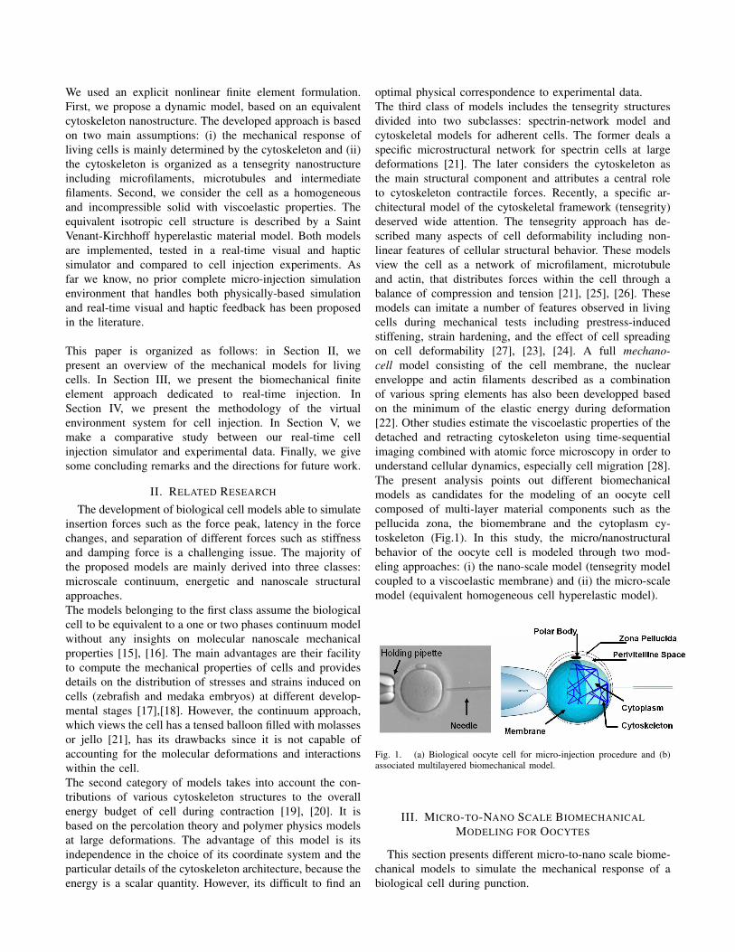
The present analysis points out different biomechanical
models as candidates for the modeling of an oocyte cell
composed of multi-layer material components such as the
pellucida zona, the biomembrane and the cytoplasm cy-
toskeleton (Fig.1). In this study, the micro/nanostructural
behavior of the oocyte cell is modeled through two mod-
eling approaches: (i) the nano-scale model (tensegrity model
coupled to a viscoelastic membrane) and (ii) the micro-scale
model (equivalent homogeneous cell hyperelastic model).
Fig. 1. (a) Biological oocyte cell for micro-injection procedure and (b)associated multilayered biomechanical model.
III. MICRO-TO-NANO SCALE BIOMECHANICAL
MODELING FOR OOCYTES
This section presents different micro-to-nano scale biome-
chanical models to simulate the mechanical response of a
biological cell during punction.

A. Nanometer Scale: Equivalent cytoskeleton structure
The first model represents the nanostructural behavior of
an oocyte cell composed of multilayer material components
with a tensegrity model coupled to a viscoelastic membrane.
It assumes that (i) the mechanical response of living cells is
mainly determined by the cytoskeleton and (ii) the cytoskele-
ton is organized as a tensegrity nanostructure. As far the
authors know, the tensegrity model has never been applied to
microrobotic intracellular injection simulation for real-time
haptic training purposes.
1) Mechanical and Geometrical Properties: The overall
structure of the tensegrity model is described as follows. The
cytoskeleton is composed of an interconnected structure of
various cross-linked interlinked filamentous biopolymers that
extends from the center to the cell surface (bio-membrane).
Three major filamentous components compose the cytoskele-
ton, i.e. the actin microfilaments, microtubules and interme-
diate filaments which are physically interlinked. The actin
stress, plays an important role in many cellular functions,
including morphological stability, adhesion, and motility.
Because of their central role in force transmission, it is
important to characterize the mechanical properties of stress
fibers [29]. However, in our studies we focus on properties
of whole cells or of actin microfilaments, microtubules and
filaments intermediate isolated outside cells [32]. Recent
study investigates the initial mechanical response of axonal
microtubule bundles under uniaxial tension using a discrete
bead-spring representation. Unfortunately, the elements in the
system, both microtubule and tau cross-link, were assumed
to follow a linear elastic constitutive relationship. This as-
sumption is less valid in an entropic stretching regime, in
compressive loading, and potentially in a high force regime
[33].
In our simulation, we choose a simplified tensegrity structure
(due to real-time simulation constraints) with six compress-
ing struts (two in each orthogonal direction), these struts
aggregate the behavior of the microtubules, viewed as beams
as shown in Fig.2. These struts are attached to 36 pre-stressed
cable segments :
• 12 cables representing the intermediate filaments which
are connected to the parallel struts.
• 24 cables representing the actin microfilaments con-
nected to the end points of each strut.
2) Formulation of the microtubule finite element model:
In this study, we propose a hybrid model well adapted
to the deformable microstructural geometry of the oocyte
cell. The biomechanical model we used is a simplified
cytoskeleton tensegrity structure where struts are modeled
with 3D first order tetrahedral finite elements and cables
with viscoelastic Kelvin-Voigt elements. Firstly, we introduce
briefly the relation between stresses and strains in the context
of hyperelastic materials for large and small deformations,
then we present the mass-tensor finite element approach
with tetrahedral elements. This non-classical finite element
approach is well-suited to perform real-time simulation.
Fig. 2. Three-dimensional finite element tensegrity model of the oocytecell (membrane surface nodes not represented).
For an isotropic elastic or St Venant-Kirchhoff hyperelastic
material the elastic energy, noted W , can be written as:
W (E) =λ
2
(trE
)2+ µ tr
(E2)
(1)
where E is the Green-Lagrange strain tensor λ and µ are the
Lame’s coefficients
E =1
2(FT .F− I)
= 1
2
(
gradU + gradT U + gradT U .gradU) (2)
A displacement based finite element solution is obtained with
the use of the principle of virtual works. Using finite element
method (FEM) notations, inside each tetrahedron T τ , the
displacement field is defined by a linear interpolation[
Nτ]
of the nodal displacement vector{
uτ}
of the four vertices
of tetrahedron:{
U(x)τ}
=[
Nτ (x)] {
uτ}
(3)
For small deformations, the Green-Lagrange strain tensor is
linearized into the infinitesimal strain tensor:
ǫ =1
2(gradU + gradT U) (4)
The relation between the Cauchy stress tensor and the
linearized strain tensor is written with Lame’s coefficient in
condensed vector notation as :{
σσσ}
= λ({
εεε}
1
+{
εεε}
2
+{
εεε}
3
) [
I]
+ 2µ{
εεε}
(5)
where[
I]
is the identity matrix.
The principle of virtual work applied to a single tetrahe-
dron T τ leads to the elementary stiffness matrix[
Kτ]
such

that the elementary nodal force vector acting on a tetrahedron
is: {
fτ}
=[
Kτ] {
uτ}
(6)
This stiffness matrix is composed of a plurality of elementary
submatrices each connecting the elementary force acting on
the node, i, to the displacement of the node, j:
[
Kτij
]
=1
36V τ
(
λ{
mi
}{
mj
}T
+ (7)
µ{
mj
}{
mi
}T
+ µ{
mi
}T {
mj
}[
I])
where{
m}
are unit outward-pointing normals to triangular
faces and V τ is the volume of the tetrahedron T τ .
Taking into account the contribution of all adjacent tetra-
hedra, the global internal force acting on a node l can be
expressed as follows:
{
Flint
}Struts
=∑
τ∈Vl
(4∑
j=1
[
Kτij
] {
uj
})
(8)
where Vl is the neighborhood of vertex l (i.e. the tetrahedra
containing node l).
The tensors[
Kτij
]
, depending on the rest geometry and
Lame’s coefficients, are constant. They can be pre-computed
in an off-line phase. It is the essential advantage of the
mass-tensor approach which makes it useful for real-time
application.
Fig. 3. Using the P1 finite element tetrahedron for the struts of thetensegrity model.
3) Cable behavior for the tensegrity structure: In this
section, we present the description of the cable behavior
about our tensegrity model (Fig.2). These pre-stressed cables
are assumed to behave as viscoelastic mass-spring-dampers.
Each cable is modeled with two masses interconnected via
spring and damper in parallel (Kelvin Voigt model). In the
local frame, the relation between the stress and the strain can
be written as follows:
σ = E ε+ η ε (9)
with σ =F
Sand ǫ =
l − l0
l0, where F is the applied load
in the extremity of the cable, l and l0 and S are respectively
the resting length of the cable, the initial length and the
section of the cable. We replace these parameters in (9), and
we obtain :
F cablelocal =
(
E S (l − l0)
l0+
η l
l0
)
x (10)
Fig. 4. Mass-spring-damper model for cable structure.
In the global coordinates, for the tensegrity structure, we
can expand this equation easily and obtain the force applied
in each node by summing the forces contributed by all nodes
connected (Fig.4). The force applied to an extremity of the
strut of the tensegrity structure is the sum of the forces
exerted by the struts and the cables.
B. Micrometer Scale : Equivalent homogeneous cell
The second model assumes that an oocyte cell could
be modeled as a whole by a homogeneous solid, isotropic
(visco)hyperelastic and nearly incompressible material prop-
erties.
1) Mechanical and Geometrical Properties: The oocyte
cell is meshed with 3D first order tetrahedral elements Fig.5.
The main geometrical characteristics of the cell were ob-
tained from experimental data. The mesh that has been used
for the non real-time simulations, was obtained by a sequence
of successive refinements until mechanical convergence. It
is constituted by a non regular tetrahedron volume mesh
composed of 1115 vertices and 322 tetrahedra where all
vertices are free. Only the surface nodes in contact with the
holding micropipette are fixed (see Fig.5).
2) Formulation of finite element model: Incompressible
and nearly-incompressible materials such as oocyte cell,
are difficult to model accurately with a pure displacement-
based FE procedure. The simplest hyperelastic (HE) material
model is the Saint Venant-Kirchhoff model which is just an
extension of the linear elastic material model to the nonlinear
regime. In our work, the cells are modeled by the volume ob-
ject discretized into a conformal tetrahedral mesh as defined
by finite element theory. Inside every tetrahedron Tk, the
displacement field is defined by a linear interpolation of the
displacement vectors of the four vertices of the tetrahedron

Fig. 5. Three-dimensional finite element model of the mouse oocyte cell.
Tk as defined by (1)-(3). Since the strain is quadratic in
displacement, the elastic energy is a fourth-order polynomial
in displacement. The relation between nodal forces and nodal
displacement is nonlinear and can be written as:
{
Fτi
}
=4∑
j=1
[
Kτij
] {
uj
}
︸ ︷︷ ︸
F τ
1
+4∑
j,k=1
{
uk
} {
uj
}T {
Cτjki
}
+1
2
{
uj
}T {
uk
}{
Cτijk
}
︸ ︷︷ ︸
F τ
2
+2
3∑
j,k,l=0
Djkli
{
ul
} {
uk
}T {
uj
}
︸ ︷︷ ︸
F τ
3
(11)
where the global force can be written as:
{
Fintl
}
=∑
τ∈Vl
({
FT1
}
︸ ︷︷ ︸
Linearforce
+{
FT2
}
+{
FT3
}
︸ ︷︷ ︸
non−linearforce
)
(12)
where{
Cτijk
}
, Dτijkl are respectively a vector and a scalar.
As these tensors depend only on the rest geometry and
Lame’s coefficients, they can be pre-computed for real-time
application.
C. Dynamic Model
The deformation of the deformable object is given by the
displacement of the nodes according to the acting external
and internal forces. In an interactive simulation the applied
forces change in time and the virtual objects have to react
to them in real time. Therefore, the FEM solution has to be
simulated dynamically. The equation of motion of a vertex l
of the cell mesh can be written:
M l{
ul
}
+ γl{
ul
}
+∑
τ∈Vl
({
Fintl
})
={
Flext
}
(13)
where M l and γl are respectively the mass and damping
coefficients of each vertex. To solve the dynamic system,
we tested different integration schemes (implicit and explicit)
taking into account the tradeoff between real-time simulation
.
Fig. 6. Computational architecture for simulating force-reflecting de-formable cell micro-injection in a virtual environment. The figure showsthe two simulation phases used for the real-time micro-injection of the cell:(i) off-line pre-calculations of stiffness matrices and (ii) simulation of visualand haptic interaction.
and haptic stability requirements. We choose the explicit
centered finite-difference scheme.
IV. 3D REAL-TIME VIRTUAL REALITY BASED ICSI
SIMULATOR
Fig.6 shows an overview of the proposed ICSI simulator.
The system includes the computer generated mesh of oocyte,
the needle, a collision detection algorithm, the physically-
based model of the deformable cell and the haptic interaction
controller. A significant difficulty in using the finite element
technique for real-time simulation is the computational cost.
These mesh-based methods require time consuming numer-
ical integration operations to perform the system stiffness
matrices. As a consequence, to spare computational time,
we adopted a computational architecture with two simula-
tion stages: (i) off-line mesh generation and computation of
elementary stiffness matrices, (ii) real-time visual and haptic
interaction during ICSI simulation.
A. Off-line computation
The most costly and time-consuming operations are
realized during a pre-calculation step. The database contains
geometric properties of oocyte cells using the micro-
injection setup image analysis. The geometry design of
oocyte cell models are based on a commercial computer-
aided design (CAD) package (MARC-ADAMS). The
meshing of the 3D internal structure is then carried out
through a dedicated 3D meshing software (GID software)
modeled in exact dimensions. Although they were displayed
as 3D texture-mapped objects to the user, they were
modeled as connected line segments to reduce the number
of collision computations during real-time interactions. The
oocyte cell was approximated as an assembly of discrete

tetrahedral elements. In order to avoid inverted or very
distorted elements due to mesh local large deformation,
the initial oocyte mesh is generated with tetrahedral
elements pre-stretched in the direction opposite to the
expected needle movement. The tetrahedral elements are
interconnected to each other through a fixed number of nodes
(see Fig.3 and Fig.5). The mechanical (Young modulus,
Fig. 7. Scheme illustrating the collision detection algorithm using a simpletriangle points intersection problem: needle intersection with triangle surfaceof the cell, and the refining of the mesh.
Poisson coefficient) and geometrical (diameter, volume)
properties of the cell structure and tensegrity parameters
are determined by real tests and injected in the FEM to
compute all the elementary tensors[
Kτij
]
,{
Cτijk
}
and Dτijkl.
B. Real-time haptics-enable simulator
We have implemented separate threads to update the loops.
During the injection task, the contact between the tip and
the cell must occur at a special set of points (nodal points).
Collision detection module specifies the type of tool-tissue
interaction. The needle, in a virtual environment, can be
modeled as a complex 3D object, composed of numerous
surfaces, edges and vertices. However, in our implementation,
since the needle can be considered as rigid, we used a point-
based representation of the pipette injector. The collision
detection is the first step to carry out realistic interactions.
However, locating the contact primitive (e.g. facets) between
two objects may be computationally expensive, especially if
the objects are composed of a large number of polygons.
In this case, we employed a simple ray-triangle intersection
with local search technique [34]. To optimize the collision
detection algorithm and cell deformation, we refine our mesh
only in a puncture area. The size of this refined area has been
empirically determined as five times the needle diameter. The
number of elements in this puncture area is fixed by the mesh
density. The scaling factor between the mesh density in the
puncture area and the rest of the cell is also fixed at five.
The visual feedback is updated after each displacement
calculation step and the haptic feedback is returned after each
force calculation step.
V. RESULTS AND VALIDATION
A. Experimental results
In order to test the accuracy and reliability of the proposed
user interface system with haptics enabled simulation, we
used experimental real data on a mouse oocyte ZP [30]. Dur-
ing experiments, the applied force is measured by a MEMS-
based two-axis cellular force sensor [31] which is capable
of resolving normal forces applied to a surface as well as
tangential forces. The geometrical dimensions are determined
by 2D image processing and reported in Table I. The oocyte
is observed to be spherical at rest: a maximum relative out of
roundness of 3.7% and a mean value of 0.5% were measured.
The mechanical properties of the homogenous cell model are
determined through a micro-injection setup [30] and reported
in Table I. The force indentation curve is shown in Fig.8. The
force increases nonlinearly as deformation increases. When
the indentation depth of the cell reaches about 45µm, the
ZP and the plasma membrane are punctured, the puncturing
forces are approximately 7.5µN . The experimental data are
plotted with 95 % prediction bounds (error bounds 5 %) for
more precision (Fig.8). As the mechanical and geometrical
properties of the tensegrity model cannot be experimentally
evaluated, these properties are settled in Table II using the
literature values [32], [35], [36]. These settling parameters
are then injected in the finite element simulation.
0 5 10 15 20 25 30 35 40−1
0
1
2
3
4
5
6
7
Indentation depth (µm)
For
ce (
µN)
Experimental dataRegression curve R²=0,9896Prediction bounds 95%
Error bounds 5%
Regression curve
Experimentaldata
Fig. 8. Experimental data: force versus needle insertion depth of the mouseoocyte cell with 95 % prediction bounds.
B. Validation of haptics-based simulator
There are two criteria for assessing the suitability of the FE
based simulator for the real-time simulation of cell puncture:
model accuracy and real-time performance. We validated the
model accuracy of our simulator for both FE models (ho-
mogeneous hyperelastic model and tensegrity model) against
the results from our least-square fitting tests as reported in
previous section. To get a trustworthy platform, the relative
error between smoothed experimental results and simulated
ones should not exceed 5%.

40µm needle insertion 30µm needle insertion 20µm needle insertion 10µm needle insertion
40µm RTS 30µm RTS 20µm RTS 10µm RTS
30 32 34 36 38 403
4
5
6
7
8
9
10
Indentation depth (µm)
Fo
rce
(µ
N)
Experimental data
Regression curve R²=0.9896
Nonlinear FEM St−Venant Kirchhoff R²=0.9885
20 22 24 26 28 301.5
2
2.5
3
3.5
4
Indentation depth (µm)
Fo
rce
(µ
N)
Experimental data
Regression curve R²=0.9896
Nonlinear FEM St−Venant Kirchhoff R²=0.9885
10 12 14 16 18 20
0.6
0.8
1
1.2
1.4
1.6
1.8
2
2.2
2.4
Indentation depth (µm)F
orc
e (
µN
)
Experimental data
Regression curve R²=0.9896
Nonlinear FEM St−Venant Kirchhoff R²=0.9885
0 2 4 6 8 100
0.1
0.2
0.3
0.4
0.5
Indentation depth (µm)
Fo
rce
(µ
N)
Experimental data
Regression curve R²=0.9896
Nonlinear FEM St−Venant Kirchhoff R²=0.9885
40µm FvD 30µm FvD 20µm FvD 10µm FvD
Fig. 9. Quantitative and qualitative comparison of the various stages of cell deformation of needle insertion between : experimental data, Real-TimeSimulations (RTS) and Force versus Displacement (FvD).
TABLE IMECHANICAL AND GEOMETRICAL PROPERTIES ASSIGNED TO THE
HOMOGENEOUS CELL MODEL.
Mechanical and geometrical properties
Young modulus 17.9KPa
Poisson coefficient 0.49
Diameter 56µm
Mass of the cell 9.1952 10−5 mg
Mesh of the cell 123 vertices and 379 tetra
Cell volume 91952µm3
Maximum indentation depth 40 ∼ 44µm
1) Case 1: Equivalent homogeneous cell model: A mesh
containing 379 tetrahedral elements and 123 vertices was
used for validation purposes. In comparison with the initial
refined mesh used in non real-time simulation, the number
of elements is decreased so as to afford real-time simula-
tions while ensuring a maximum relative error of 5% in
comparison with the converged refined mesh. The mechan-
ical and geometrical properties used in the finite element
simulations are settled in Table.I. The Fig. 10 and Fig. 9
show comparisons between experimental data, linear and
non-linear finite element responses. In order to represent
a nearly incompressible material behavior, a numerically
acceptable value of ν=0.49 was adopted. The reaction force is
plotted versus the needle insertion depth. The force feedback
simulations shown in Fig. 9 demonstrate that the non-linear
FE St-Venant-Kirchhoff model is in good agreement with
experimental data. For comparison purposes, it can be clearly
seen that a linear finite element model is valid only for
small displacements (less than 10 % of the mesh size).
The visual realism of the simulation tests depicted in (Fig.
9) demonstrates the good agreement of visual deformation
rendered to the operator at various stages of needle insertion.
0 10 20 30 40 500
1
2
3
4
5
6
7
8
Indentation depth (µm)
Fo
rce
(µ
N)
Experimental dataRegression curve R²=0.9896Nonlinear FEM St−Venant Kirchhoff R²=0.9885Linear FEM
Linear FEM
Experimental data
Non−linear FEM
95% predictionbounds
Fig. 10. Force versus indentation depth: comparison between experimentaldata, non-linear St Venant Kirchhoff and linear finite element simulations.
2) Case 2: Equivalent cytoskeleton structure model: The
mesh that was used for the following simulations is shown in
Fig. 3. It is constituted by a non regular tetrahedron volume
mesh composed of 1014 vertices and 1798 tetrahedrons

where all vertices are free and only three nodes are fixed (see
Fig. 2). It should be noticed that the viscoelastic biomem-
brane is not represented for simplicity of representation.
TABLE IIMATERIAL AND GEOMETRICAL PROPERTIES ASSIGNED TO THE
TENSEGRITY MODEL: ACTIN FILAMENTS (AF), MICRO TUBULES (MT)AND INTERMEDIATE FILAMENTS (IF), WHERE BS: BENDING STIFFNESS,
S: SECTION OF THE FILAMENTOUS [32].
AF MT IF
E (Pa) 1.3 ∼ 2.6× 10⁹
1.2× 10⁹
0.3 ∼ 0.4× 10⁹
ν 0.3 0.3 0.3D (nm) − 5 −
BS (Nm2) 7× 10⁻²⁶
2.6× 10⁻²³
4 ∼ 12× 10−27
Mesh cable 1014 vertices cable1798 tetrahedra
In figure 11, we show two static qualitative examples of the
deformation of a tensegrity structure. Firstly, the penetration
axis of the micropipette is supposed to be aligned with the
tensegrity geometrical center. The resulting force is applied
to the center of one strut of the tensegrity model. Secondly,
the penetration axis of the micropipette is supposed to be
parallel to the first load but the resulting force is applied in
the extremity of a strut. The deformed meshes show the effect
of the deformation of one member on the whole tensegrity
structure.
Fig. 11. Deformed tensegrity meshes. Case 1; the force is applied to themiddle of a strut, Case 2; the force is applied in the extremity of a strut.
The figure 12 shows the non-linear response of the tenseg-
rity cell model during a needle insertion. The non-linear
increase in cell stiffness as a result of increasing prestress
exhibited by the model is attributed to the internal cytoskele-
ton. This effect is also seen when forces are applied at a
distance from the underlying cytoskeleton, although the effect
is less pronounced. As illustration, the Fig. 13 shows the
nonlinear response of the cell tensegrity structure compared
to experimental data. These results are qualitatively in good
agreement with the experimental results but presents lower
deformation forces due to a lack of accuracy in the deter-
mination of the Young modulus parameters (microtubules,
microfilaments and intermediate filaments).
0 5 10 15 200
0.02
0.04
0.06
0.08
0.1
Displacement (µm)
For
ce (
µN)
Force versus displacementtensegrity model
Fig. 12. Force versus needle insertion depth for tensegrity model.
For real-time performance, we need only around 24-25
Hz screen refresh rate for visual updates, which corresponds
to the critical fusion frequency of human eye. However, the
human tactile sensory system is much more sensitive, hence
the haptic device requires an update rate between 300Hz and
1 kHz. To test the real-time performance of the standard CPU
implementation, we used meshes of different complexity with
the number of elements ranging from 100 to 5000. An ex-
perimental system was implemented on a personal computer
with a Intel Core Duo 3.2 GHz CPU with 4 GB memory, and
GeForce 8600 GTS with 512Mo memory. In this experiment,
we investigated the time required for pre-computation (off-
line computation) and the real-time deformation process by
changing the number of vertices of a cell model (Table.III).
The relationship between the number of vertices and the off-
line computation time was identified by a nonlinear law while
the relation between the number of vertices and the real-time
simulation remains quasi-linear (see Fig.14). However, the
accuracy of the finite element analysis depends on the mesh
refinement. The problem should be solved by using graphics
processing unit (GPU) to perform finer mesh simulations.
Fig. 13. Force versus indentation depth: comparison between experimentaldata, micro/nano structural tensegrity model and homogeneous non-linearviscoelastic FE .
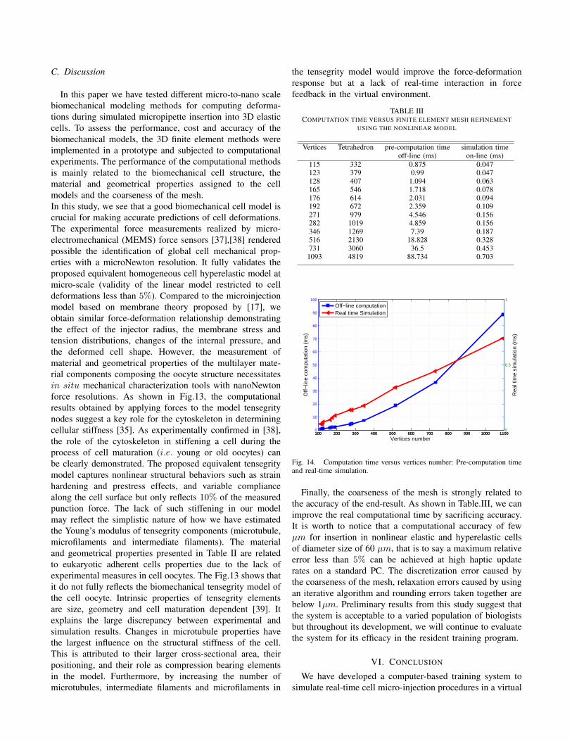
C. Discussion
In this paper we have tested different micro-to-nano scale
biomechanical modeling methods for computing deforma-
tions during simulated micropipette insertion into 3D elastic
cells. To assess the performance, cost and accuracy of the
biomechanical models, the 3D finite element methods were
implemented in a prototype and subjected to computational
experiments. The performance of the computational methods
is mainly related to the biomechanical cell structure, the
material and geometrical properties assigned to the cell
models and the coarseness of the mesh.
In this study, we see that a good biomechanical cell model is
crucial for making accurate predictions of cell deformations.
The experimental force measurements realized by micro-
electromechanical (MEMS) force sensors [37],[38] rendered
possible the identification of global cell mechanical prop-
erties with a microNewton resolution. It fully validates the
proposed equivalent homogeneous cell hyperelastic model at
micro-scale (validity of the linear model restricted to cell
deformations less than 5%). Compared to the microinjection
model based on membrane theory proposed by [17], we
obtain similar force-deformation relationship demonstrating
the effect of the injector radius, the membrane stress and
tension distributions, changes of the internal pressure, and
the deformed cell shape. However, the measurement of
material and geometrical properties of the multilayer mate-
rial components composing the oocyte structure necessitates
in situ mechanical characterization tools with nanoNewton
force resolutions. As shown in Fig.13, the computational
results obtained by applying forces to the model tensegrity
nodes suggest a key role for the cytoskeleton in determining
cellular stiffness [35]. As experimentally confirmed in [38],
the role of the cytoskeleton in stiffening a cell during the
process of cell maturation (i.e. young or old oocytes) can
be clearly demonstrated. The proposed equivalent tensegrity
model captures nonlinear structural behaviors such as strain
hardening and prestress effects, and variable compliance
along the cell surface but only reflects 10% of the measured
punction force. The lack of such stiffening in our model
may reflect the simplistic nature of how we have estimated
the Young’s modulus of tensegrity components (microtubule,
microfilaments and intermediate filaments). The material
and geometrical properties presented in Table II are related
to eukaryotic adherent cells properties due to the lack of
experimental measures in cell oocytes. The Fig.13 shows that
it do not fully reflects the biomechanical tensegrity model of
the cell oocyte. Intrinsic properties of tensegrity elements
are size, geometry and cell maturation dependent [39]. It
explains the large discrepancy between experimental and
simulation results. Changes in microtubule properties have
the largest influence on the structural stiffness of the cell.
This is attributed to their larger cross-sectional area, their
positioning, and their role as compression bearing elements
in the model. Furthermore, by increasing the number of
microtubules, intermediate filaments and microfilaments in
the tensegrity model would improve the force-deformation
response but at a lack of real-time interaction in force
feedback in the virtual environment.
TABLE IIICOMPUTATION TIME VERSUS FINITE ELEMENT MESH REFINEMENT
USING THE NONLINEAR MODEL
Vertices Tetrahedron pre-computation time simulation timeoff-line (ms) on-line (ms)
115 332 0.875 0.047123 379 0.99 0.047128 407 1.094 0.063165 546 1.718 0.078176 614 2.031 0.094192 672 2.359 0.109271 979 4.546 0.156282 1019 4.859 0.156346 1269 7.39 0.187516 2130 18.828 0.328731 3060 36.5 0.453
1093 4819 88.734 0.703
100 200 300 400 500 600 700 800 900 1000 11000
10
20
30
40
50
60
70
80
90
100
Vertices number
Off−
line
com
puta
tion
(ms)
100 200 300 400 500 600 700 800 900 1000 11000
0.5
1
Rea
l tim
e si
mul
atio
n (m
s)
Off−line computationReal time Simulation
Fig. 14. Computation time versus vertices number: Pre-computation timeand real-time simulation.
Finally, the coarseness of the mesh is strongly related to
the accuracy of the end-result. As shown in Table.III, we can
improve the real computational time by sacrificing accuracy.
It is worth to notice that a computational accuracy of few
µm for insertion in nonlinear elastic and hyperelastic cells
of diameter size of 60 µm, that is to say a maximum relative
error less than 5% can be achieved at high haptic update
rates on a standard PC. The discretization error caused by
the coarseness of the mesh, relaxation errors caused by using
an iterative algorithm and rounding errors taken together are
below 1µm. Preliminary results from this study suggest that
the system is acceptable to a varied population of biologists
but throughout its development, we will continue to evaluate
the system for its efficacy in the resident training program.
VI. CONCLUSION
We have developed a computer-based training system to
simulate real-time cell micro-injection procedures in a virtual

environment for training biologist residents. The simulator
provides the user with visual and haptic feedback. The sim-
ulation procedure involves a real-time rendering through the
haptic interactions with a physically-based model. We first
investigated the challenging issues in the real-time modeling
of the biomechanical properties of the cell micro-injection
through finite element models. Compared to experimental
data performed on oocyte cells, we can see clearly that the
proposed physically-based FEM model is able to simulate
the cell deformation through real-time simulation constraints.
Currently, we are working on integrating others effects such
as friction, viscosity, and adhesion forces. The simulator is
prepared to doing an experimental training evaluation from
trained and non-trained candidates. All modalities will be
merged in an ergonomic and intelligent biological simulator
to support learning micro-injection and training tasks.
REFERENCES
[1] T. Ebner, C. Yaman, M. Moser, M. Sommergruber, K. Jesacher, G.Tews, ”A prospective study on oocyte survival rate after ICSI influenceof injection technique and morphological features”, J Assist Reprod
Genet 18, pp. 601-606, 2001.
[2] S. Yu, B.J. Nelson, ”Microrobotic Cell Injection”, IEEE International
Conference on Robotics and Automation ,Seoul, Korea, , pp. 620-625,2001.
[3] Y.H. Anis, M.R. Holl, D. R. Meldrum, Automated selection andplacement of single cells using vision-based feedback control, IEEETransactions on Automation Science and Engineering, Vol.7, No.3,pp.598-606, 2010.
[4] W.H. Wang, X.Y. Liu, Y. Sun, High-Throughput automated injection ofindividual biological cells,IEEE Transactions on Automation Science
and Engineering, Vol.6, No.2, pp.598-606, 2009.
[5] A. Pillarisetti, M. Pekarev, A. D. Brooks, J. P. Desai, ”Evaluating theEffect of Force Feedback in Cell Injection”, IEEE Transactions on
Automation Science and Engineering, 2007, 4(3): pp. 322-331.
[6] H. Ladjal, J.L. Hanus and A.Ferreira, ”Interactive Cell InjectionSimulation Based on 3D bio-mechanical Tensegrity Model”, IEEE
International Conference on Robots and Intelligent Systems (IROS’08),September 22-26, 2008, Nice, France, Page 2296-2302.
[7] U. Meier, O. Lopez, C. Monserrat, M.C. Juan, M. Alcaniz, ”Real-timedeformable models for surgery simulation: a survey”, Comput Methods
Programs Biomed, 77(3), pp. 183-197, 2005.
[8] J. Kim, C. Choi, S. De, M.A. Srinivasan, ”Virtual surgery simulationfor medical training using multi-resolution organ models”, Int J Med
Robotics Comput Assist Surg, 3, pp. 149-158, 2007
[9] J. Kim, H. Ladjal, D. Folio, A. Ferreira and J.K. Kim, Evaluation ofTelerobotic Shared Control Strategy for Efficient Single Cell Manip-ulation. IEEE Transactions on Automation Science and Engineering
(T-ASE ), 9(2), pp. 402-406, ISSN 1545-5955. 2012.
[10] N. Bolhassani, R. Patel, M. Moallem , ”Needle insertion into soft tissue: A survey”, Med Eng Phys, 29 (4), pp. 413-431, 2007.
[11] M. Ammi, H. Ladjal, A. Ferreira, ”Evaluation of 3D Pseudo-HapticRendering using Vision for Cell Micromanipulation”, IEEE Intelligent
Robots and Systems, Beijing, China, 2006, 2115 - 2120
[12] M. Asgari, A. Ghanbari, S. Nahavandi ”3D Particle-based cell mod-elling for haptic microrobotic cell injection”, 15th International Confer-ence on Mechatronics Technology Melbourne, Australia, pp.1-6, 2011.
[13] V. Lulevich, T. Zink, H-Y. Chen, F-T. Liu, G-y. Liu, ”Cell Mechanicsusing Atomic Force Microscopy-based Single-Cell Compression”,Langmuir, vol. 22, no. 19, pp. 8151 -8155, 2006.
[14] H. Ladjal, J.L. Hanus, A. Pillarisetti, C. Keffer, A.Ferreira and J.P. De-sai, ”Reality-based real-time Cell Indentation Simulator”, IEEE/ASME
Transactions on Mechatronics, Vol. 17, Issue: 2, pp. 239 - 250 2012.
[15] C.T. Lim, E.H. Zhou, S.T. Quek, Mechanical models for living cells- A review, Journal of Biomechanics, 39, 2, 195-216, 2006.
[16] T. Omori, T. Ishikawa, D. Barths-Biesel, A.-V. Salsac, J. Walter, Y.Imai, and T. Yamaguchi, Comparison between spring network modelsand continuum constitutive laws: application to the large deformationof a capsule in shear flow, Phys. Rev. E, 83, 041918, 2011.
[17] Y. Tan, D. Sun, W. Huang, S-H. Cheng, Mechanical modeling of bio-logical cells in microinjection, IEEE Transactions on Nanobioscience,vol.7, No.4, pp.257-266, 2008.
[18] Y. Tan, D. Sun, W. Huang, S-H. Cheng, Characterizing MechanicalProperties of Biological Cells by Microinjection, IEEE Transactions
on Nanobioscience, vol. 9, NO. 3, pp.71-180, 2010.[19] K. Kruse, J. F. Joanny, F. Jlicher, J. Prost, and K. Sekimoto, Generic
theory of active polar gels : a paradigm for cytoskeletal dynamics, Eur
Phys J E Soft Matter, 16(1), pp.5-16, 2005.[20] F. Julicher, K. Kruse, J. Prostc b, and J.-F. Joanny. Active behavior of
the cytoskeleton. Physics Reports, vol. 449, Issues 1(3) pp.3-28, 2007.[21] D.E. Ingber, Tensegrity: the architectural basis of cellular mechan-
otransduction, Annual Review of Physiology,59 (1), pp.575-599, 1997.
[22] Y. Ujihara, M. Nakamura, H. Miyazaki, S. Wada, Proposed springnetwork cell model based on a minimum energy concept, Annals of
Biomedical Engineering 38, pp.1530-1538, 2010.[23] Y. Zeng, A.K. Yip, S.K. Teo, K.H.Chiam, A three-dimensional random
network model of the cytoskeleton and its role in mechanotransductionand nucleus deformation, Biomechanics and Modeling in Mechanobi-
ology, 11, pp.49-59, 2012.[24] K. Wang, D. Sun, Influence of semiflexible structural features of actin
cytoskeleton on cell stiffness based on actin microstructural modeling,Journal of Biomechanics, 45, pp.1900-1908, 2012.
[25] Y. Ruiguo, X. Ning, K.M.F.Carmen, S.S. Kristina, W.C.Lai. King, S.Bo, A.S. Animesh, Cellular tensegrity modeling with Atomic ForceMicroscopy (AFM) experimentation, IEEE Nanotechnology Materials
and Devices Conference, pp.65-70, 2010.[26] M. Mehrbod, M.R.K. Mofrad, On the significance of microtubule
flexural behavior in cytoskeletal mechanics. PLoS One 6:e25627, 2011[27] B. Maurin, P. Canadas, H. Baudriller,P. Montcourrier, N. Bettache,
”Mechanical model of cytoskeleton structuration during cell adhesionand spreading”, Journal of Biomechanics, vol.41, pp. 2036-2041, 2008.
[28] Y.S. Hee, L. ChanMo, M.R.K. Mofrad, Viscoelastic characterizationof the retracting cytoskeleton using subcellular detachment, AppliedPhysics Letters, 98, 133701 2011
[29] L. Lan, J.O. Sara, N. Hai, F.C.P. Yin, Mechanical properties of actinstress fibers in living cells, Biophysical Journal, Volume 95, Issue 12,pp. 6060-6071, 2008.
[30] Y. Sun, K. Wan, K.P. Roberts, J.C. Bischof, B.J. Nelson,”Mechanicalproperty characterization of mouse zona pellucida”, IEEE Transactions
On NanoBioscience, Vol. 2, No. 4, 2003.[31] Y. Sun, B. J. Nelson, D. P. Potasek, and E. Enikov, A bulk microfabri-
cated multi-axis capacitive cellular force sensor using transverse combdrives, J. Micromech. Microeng., vol. 12, no. 6, pp. 832-840, 2002.
[32] M.R.K. Mofrad and R.D. Kamm , Cytoskeletal Mechanics: Modelsand Measurements in Cell Mechanics (Cambridge Texts in BiomedicalEngineering) Cambridge University Press, 978-0-521-84637, 2006.
[33] S.J. Peter, M.R.K. Mofrad , Computational Modeling of AxonalMicrotubule Bundles under Tension. Biophysical Journal, Volume 102,Issue 4, 749-757, 22 February 2012
[34] T. Moller, B. Trumbore, ”Fast, Minimum Storage Ray-Triangle Inter-section”, Journal of graphics tools, vol. 2, no. 1, pp.21-28, 1997.
[35] J.G. McGarry, P.J. Prendergast, A three-dimensional finite elementmodel of an adherent eukaryotic cell, European Cells and Materials,Vol. 7, pp.27-34, 2004.
[36] O.I. Wagner, S. Rammensee, N. Korde, Q. Wen, J.F. Leterrier, P.A.Janmey , Softness, strength and self-repair in intermediate filamentnetworks, Experimental Cell Research, 313(10), pp. 2228-2235, 2007.
[37] X. Liu, Y. Sun, W. Wang, B.M. Lansdorp, ”Vision-based cellularforce measurement using an elastic microfabricated device”, Journal of
Micromechanics and Microengineering, Vol.17, 2007, pp.1281-1288.[38] X. Liu, R. Fernandes, A. Jurisicova, R.F. Casper, Y. Sun , In situ
mechanical characterization of mouse oocytes using a cell holdingdevice, Lab on a Chip, 10, pp. 2154-2161, 2010.
[39] J.S. Milner, M.W. Grol , K.L. Beaucage 3, S.J. Dixon, D.W.Holdsworth, Finite-Element Modeling of Viscoelastic Cells Dur-ing High-Frequency Cyclic Strain, J. Funct. Biomater, 3, 209-224;doi:10.3390/jfb3010209, 2012.

Hamid Ladjal received the M.S. degree in vir-tual reality and complex systems from Evry-Vald’Essone University, France, and the Engineer de-gree in electronics and computing from USTHB,and the Ph.D. degree in robotics and computerscience from the University of Orlans, France, in2010. He is currently an Associate Professor ofcomputer science and biomechanical modeling atthe Lyon Claude Bernard university, the imageprocessing and information system (LIRIS CNRSUMR 5205), and the Institute of Nuclear physics
of Lyon (IPNL CNRS UMR 5822), France. In 2009, he was a visitingresearcher in the Robotics, Automation, and Medical Systems Laboratory,Maryland, USA. His research interests include mutliphysical, multiscalemodeling and finite-element analysis, organ motion, reality-based soft-tissuemodeling for real-time interaction, medical imaging and image processing,haptic interaction, cell characterization, and cell biomechanics, micro/nanomanipulation.
Jean-Luc Hanus received the M.S. degree fromthe National Aerospace and Mechanical Engin-neering School, France, in 1993, and the Ph.D.degree in mechanical engineering from the Uni-versity of Poitiers, Poitiers, France, in 1999. Heis currently an Assistant Professor of mechani-cal engineering at the Ecole Nationale Suprieured’Ingnieurs de Bourges, Bourges, France. His re-search interests include the area of nonlinear me-chanical models and efficient numerical methodsin dynamic analysis of biological cell and tissue
responses.
Antoine Ferreira (M’04) received the M.S. andPh.D. degrees in electrical and electronics en-gineering from the University of Franche-Comt,Besancon, France, in 1993 and 1996, respectively.In 1997, he was a Visiting Researcher in the Elec-troTechnical Laboratory, Tsukuba, Japan. He iscurrently a Professor of robotics engineering at theLaboratoire PRISME, Ecole Nationale Suprieured’Ingnieurs de Bourges, Bourges, France. He is anauthor of three books on micro- and nanoroboticsand more than 150 journal and conference papers
and book contributions. His research interests include the design, modeling,and control of micro and nanorobotic systems using active materials,micro- and nanomanipulation systems, biological nanosystems, and bio-nanorobotics. Dr. Ferreira was the Guest Editor for different special issuesof the IEEE/ASME Transactions on Mechatronics in 2009, InternationalJournal of Robotics Research in 2009, and the IEEE NanotechnologyMagazine in 2008, IEEE Transactions on Robotics in 2013. He is actuallyassociate editor in Reviews in Advanced Sciences and Engineering.


![Constraints Assisted Modeling and Validation Presented in CS294-5 (Spring 2007) Thomas Huining Feng Based on: [1]Constraints Assisted Modeling and Validation](https://img.pdfslide.net/doc/110x75/5697bfe91a28abf838cb6d2e/constraints-assisted-modeling-and-validation-presented-in-cs294-5-spring-2007.jpg)