Embed Size (px)
Citation preview
dSPACE
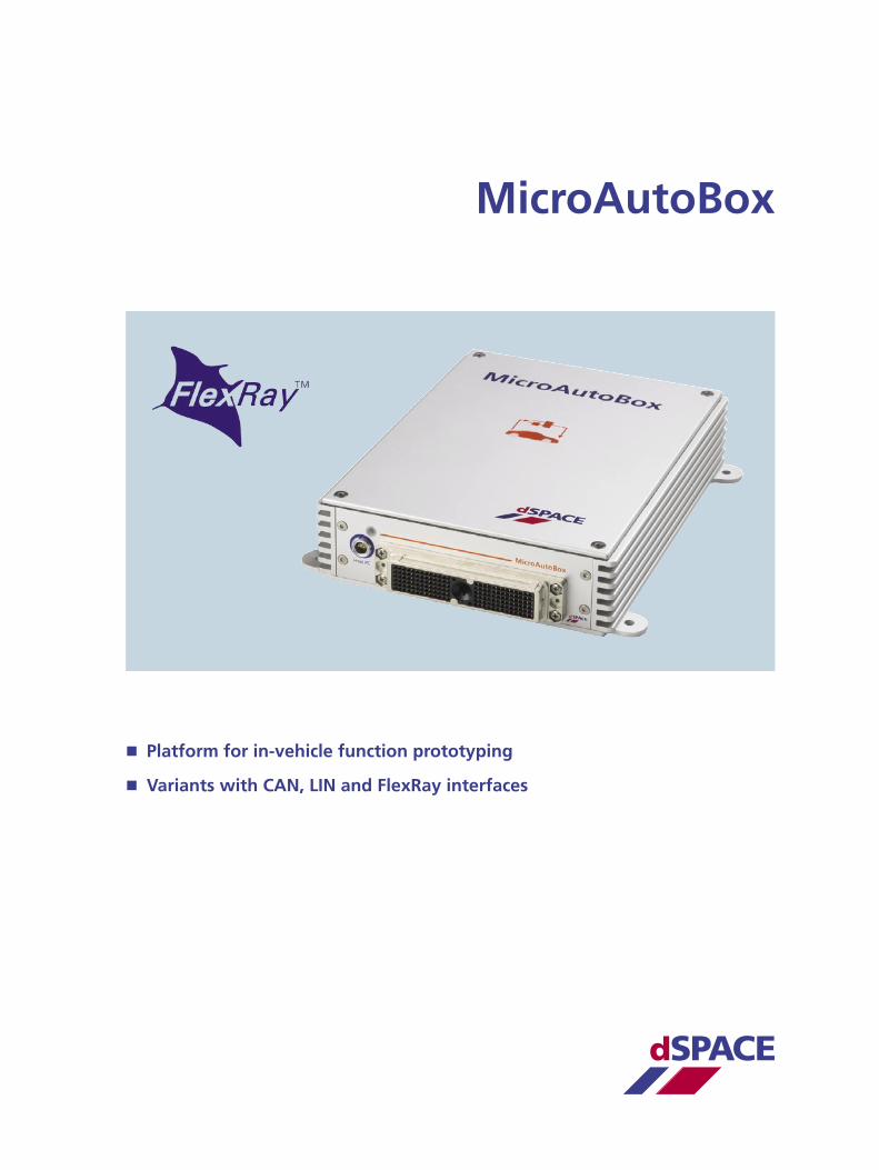
MicroAutoBox
Platform for in-vehicle function prototyping
Variants with CAN, LIN and FlexRay interfaces
20082
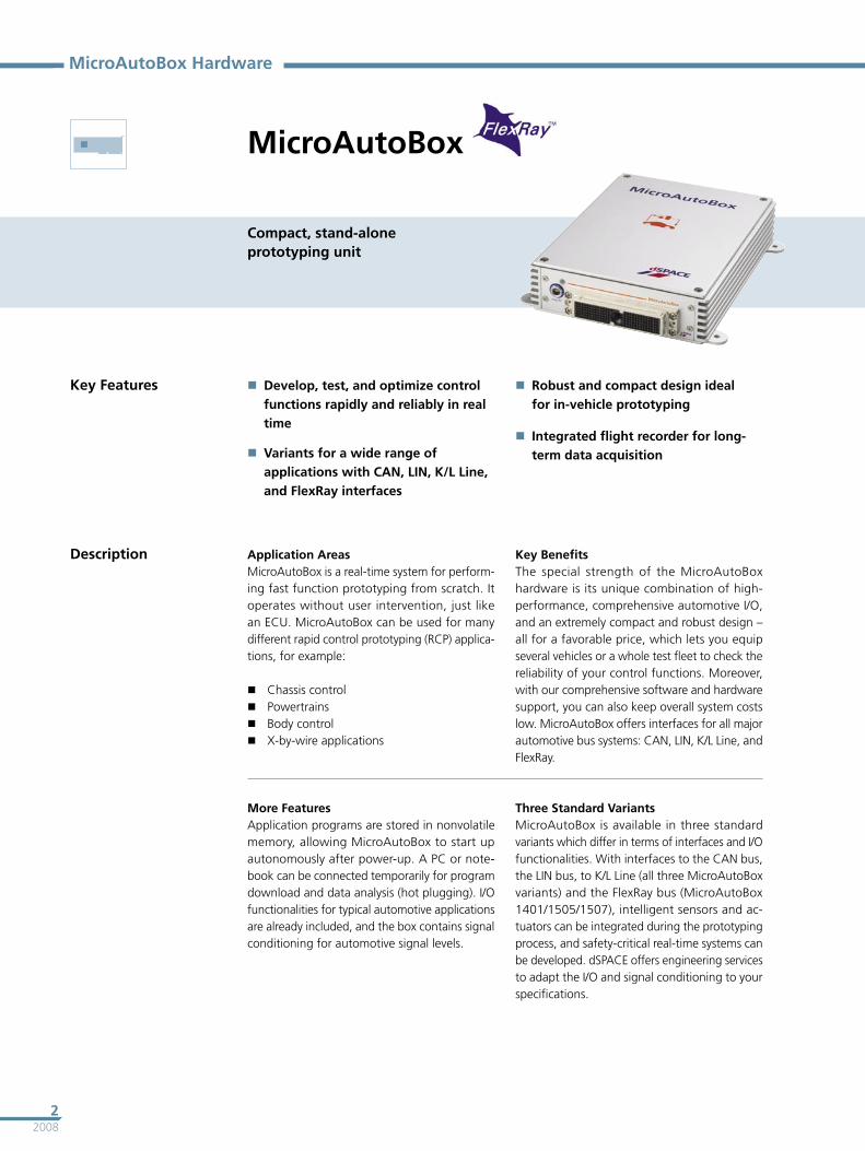
MicroAutoBox
MicroAutoBox Hardware
Compact, stand-alone prototyping unit
Key Features Develop, test, and optimize control functions rapidly and reliably in real time
Variants for a wide range of applications with CAN, LIN, K/L Line, and FlexRay interfaces
Robust and compact design ideal for in-vehicle prototyping
Integrated flight recorder for long-term data acquisition
Description Application AreasMicroAutoBox is a real-time system for perform-ing fast function prototyping from scratch. It operates without user intervention, just like an ECU. MicroAutoBox can be used for many different rapid control prototyping (RCP) applica-tions, for example: Chassis control Powertrains Body control X-by-wire applications
Key BenefitsThe special strength of the MicroAutoBox hardware is its unique combination of high- performance, comprehensive automotive I/O, and an extremely compact and robust design – all for a favorable price, which lets you equip several vehicles or a whole test fleet to check the reliability of your control functions. Moreover, with our comprehensive software and hardware support, you can also keep overall system costs low. MicroAutoBox offers interfaces for all major automotive bus systems: CAN, LIN, K/L Line, and FlexRay.
Three Standard VariantsMicroAutoBox is available in three standard variants which differ in terms of interfaces and I/O functionalities. With interfaces to the CAN bus, the LIN bus, to K/L Line (all three MicroAutoBox variants) and the FlexRay bus (MicroAutoBox 1401/1505/1507), intelligent sensors and ac-tuators can be integrated during the prototyping process, and safety-critical real-time systems can be developed. dSPACE offers engineering services to adapt the I/O and signal conditioning to your specifications.
More FeaturesApplication programs are stored in nonvolatile memory, allowing MicroAutoBox to start up autonomously after power-up. A PC or note-book can be connected temporarily for program download and data analysis (hot plugging). I/O functionalities for typical automotive applications are already included, and the box contains signal conditioning for automotive signal levels.
32008
MicroAutoBox
Technical Details
Parameter Specification
MicroAutoBox 1401/1501 1401/1504 1401/1505/1507
Processor IBM PPC 750FX, 800 MHz
Memory 8 MB main memory 4 MB memory exclusively for communication between MicroAutoBox and PC/notebook 16 MB nonvolatile flash memory containing code section and flight recorder data Clock/calendar function for time-stamping of flight recorder data
Interfaces CAN interface
Dual CAN interface; 2 CAN channels in total
Two dual CAN interfaces; 4 CAN channels in total
Two dual CAN interfaces; 4 CAN channels in total
Serial interface (based on CAN processor)
1 x RS232 interface 1 x RS232 interface 2 x RS232 interface
1 x serial interface usable as K/L-Line or LIN interface
1 x serial interface usable as K/L-Line or LIN interface
2 x serial interface usable as K/L-Line or LIN interface
ECU interface
Dual-port memory interface, 16 K x 16-bit DPRAM
–
2 x dual-port memory interfaces, 16 K x 16-bit DPRAM
FlexRay interface – – Up to 2 slots for FlexRay modules
Analog input Resolution 16 12-bit channels 24 12-bit channels 16 12-bit channels
Sampling
4 to 1 multiplexed Simultaneous sample & hold
Input voltage range
0 ... 5 V
Analog output Resolution 8 12-bit channels – 8 12-bit channels
Output voltage range
0 ... 4.5 V
Output current 5 mA max. sink/source current
Digital I/O General
Digital I/O on 68336 slave processor, 20 MHz, with time processor unit (TPU) I/O software support for different applications
Bit I/O
16 discrete inputs 10 discrete outputs, 5 mA output current 16 shared discrete inputs/outputs, bit-selectable 16 TPU channels Up to 16-bit resolution
PWM generation/measurement
4 shared inputs for frequency or PWM 4 PWM outputs, PWM frequency 2.5 Hz ... 100 kHz, duty cycle 0 ... 100% Up to 16-bit resolution
Signal conditioning Signal conditioning for automotive signal levels, no power driver included Overvoltage protection Overcurrent and short circuit protection
Physical connections Connection to a notebook/PC for program load, experiment configuration, signal monitoring and flight recorder read-out
ZIF connector for I/O signals and power supply, mechanically secured Additional 78-pin Sub-D connector with MicroAutoBox 1401/1505/1507 High-speed host interface (100 megabits/s technology) Support of PCMCIA, PCI, and ISA host connections Cable length of up to 10 meters
MicroAutoBox
20084
MicroAutoBox Hardware
Parameter Specification
MicroAutoBox 1401/1501 1401/1504 1401/1505/1507
Physical characteristics
Enclosure material Cast aluminum box
Enclosure size
Approx. 200 x 225 x 50 mm (7.9 x 8.9 x 2.0 in)
Approx. 200 x 225 x 50 mm (7.9 x 8.9 x 2.0 in)
Approx. 200 x 225 x 95 mm (7.9 x 8.9 x 3.8 in)
Ambient temperature
Operating temperature: -40 ... +85 °C (-40 ... 185 °F) Storage temperature: -55 ... +125 °C (-67 ... +257 °F)
Power supply 6 ... 40 V input power supply, protected against overvoltage and reverse polarity
Power consumption
Max. 20 W
Products Order Number (with PCMCIA Link) Order Number (with PCI Bus Link)
MicroAutoBox 1401/1501 MABX 1401/1501_815 MABX 1401/1501_817
MicroAutoBox 1401/1505 MABX 1401/1505_815 MABX 1401/1505_817
MicroAutoBox 1401/1505/1507 MABX 1401/1505/1507_815 MABX 1401/1505/1507_817
Order Information
Relevant Software and Hardware
Software Order Number
Included Data retrieval utility for flight recorder read-out –
Comprehensive C libraries (e.g., digital I/O support)
–
Required Real-Time Interface RTI
Microtec PowerPC C Compiler CCPPPC
Optional ControlDesk Standard – Developer Vers. CS_D
ControlDesk Standard – Operator Vers. CS_O
MLIB/MTRACE MLIB/MTRACE
RTI CAN Blockset RTICAN_BS
RTI CAN MultiMessage Blockset RTICANMM_BS
RTI LIN Blockset RTILIN_BS
RTI LIN MultiMessage Blockset RTILINMM_BS
dSPACE FlexRay Configuration Package FLEXRAY_CONF_TOOL
RTI Bypass Blockset RTIBYPASS_BS
Hardware Order Number
Optional DS4340 FlexRay Interface Module (see p. 11) DS4340
52008
MicroAutoBox
CertificationsStandardsLike all dSPACE hardware products, MicroAuto-Box meets the requirements of the European Committee for Electrotechnical Standardization (CENELEC) and is therefore CE-compliant: EN 61000-6-2: Immunity standard for
industrial environments EN 61000-6-4: Emission standard for
industrial environments
Quality TestsTo verify their reliability under realistic operat-ing conditions, all three standard MicroAuto-Box variants were exposed to extreme shock and vibration tests. During the test, MicroAutoBox continuously executed a program without any failures. It is also shock- and vibration-tested up to 100 g.
Certification Description
EN 60068-2-6 Mechanical test: resistance to vibration: Sinusoidal vibration, 3-axis test, 5 ... 2000 Hz, up to 5 g, 30 minutes per axis
EN 60068-2-27 Mechanical test: shock resistance:Shock, 3-axis test, 11 ms at 15 g, 5 ms at 100 g
Other Prototyping Systems
Differences to Other Prototyping Systems
AutoBox System MicroAutoBox ECU
Processor Scalable, floating-point Floating-point Fixed-point or floating-point, target type
Memory Large, expandable Large Limited
I/O Flexible, modular Fixed1) Application-specific, fixed
Signal conditioning
External Built-in Built-in
Size Fairly large Small Small
Operation PC or PCMCIA AutoBoot Stand-alone or PC Stand-alone
Programming Easy Easy Difficult 1) Custom-specific modifications possible.
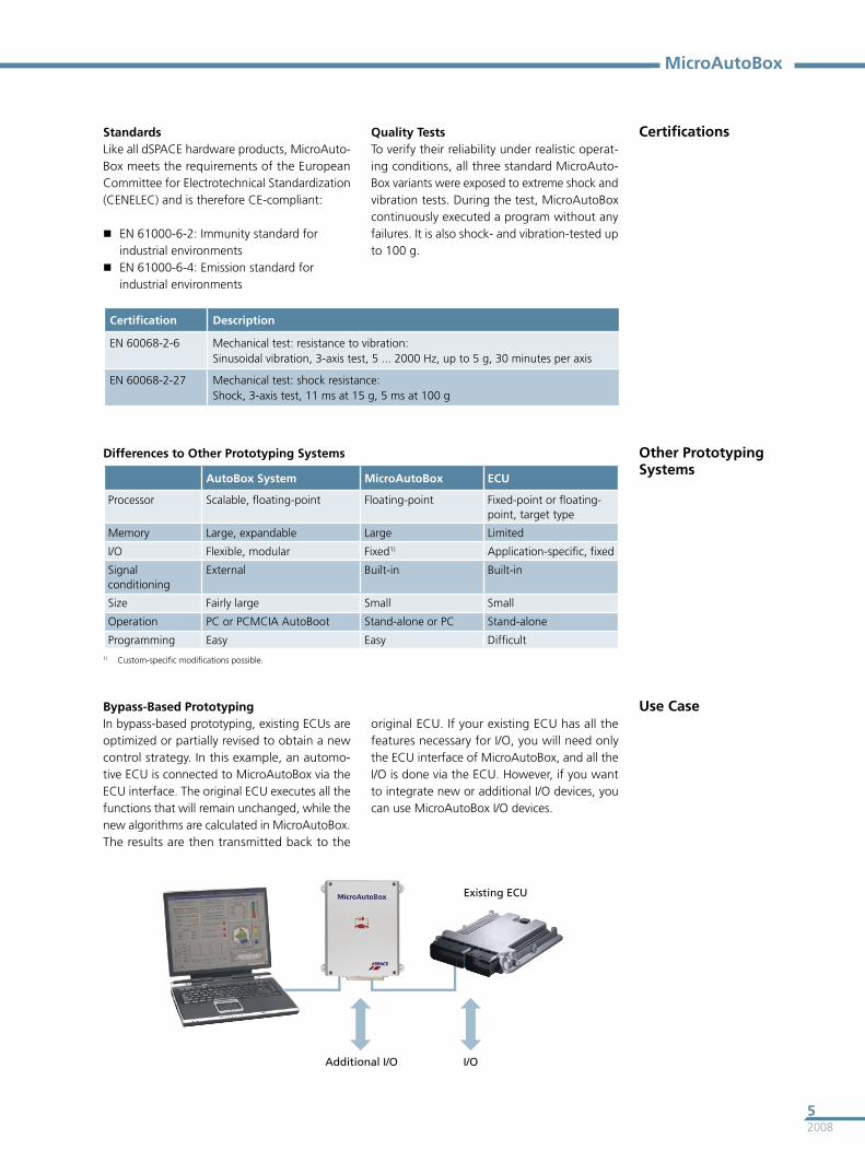
Use CaseBypass-Based PrototypingIn bypass-based prototyping, existing ECUs are optimized or partially revised to obtain a new control strategy. In this example, an automo-tive ECU is connected to MicroAutoBox via the ECU interface. The original ECU executes all the functions that will remain unchanged, while the new algorithms are calculated in MicroAutoBox. The results are then transmitted back to the
Existing ECU
I/OAdditional I/O
original ECU. If your existing ECU has all the features necessary for I/O, you will need only the ECU interface of MicroAutoBox, and all the I/O is done via the ECU. However, if you want to integrate new or additional I/O devices, you can use MicroAutoBox I/O devices.
20086
MicroAutoBox Hardware
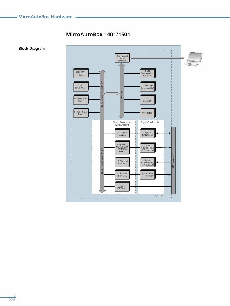
MicroAutoBox 1401/1501
Block Diagram
72008
MicroAutoBox
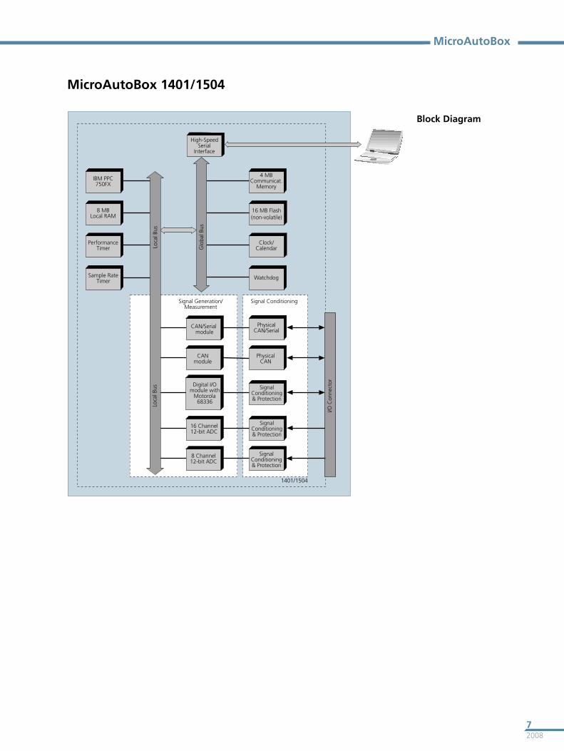
MicroAutoBox 1401/1504
Block Diagram
20088
MicroAutoBox Hardware
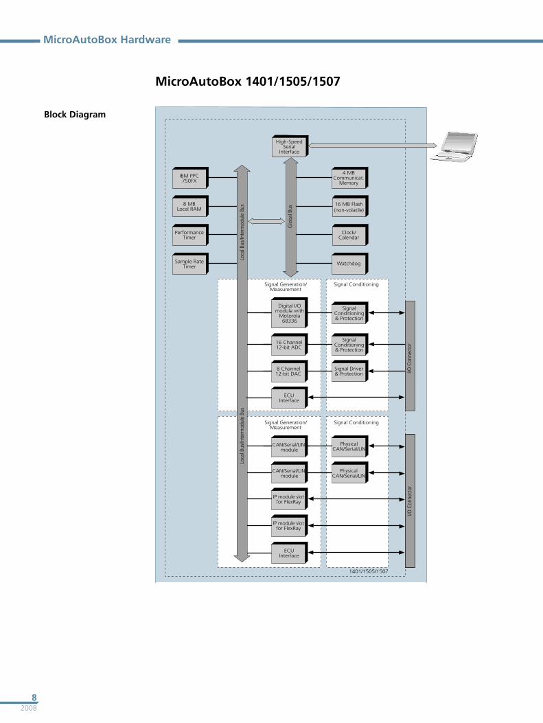
MicroAutoBox 1401/1505/1507
Block Diagram
92008
MicroAutoBox
Digital I/O Software Support
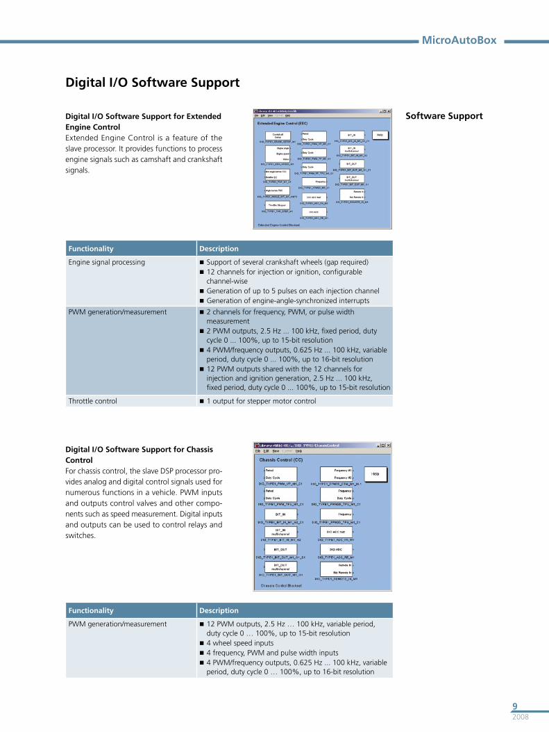
Software SupportDigital I/O Software Support for Extended Engine ControlExtended Engine Control is a feature of the slave processor. It provides functions to process engine signals such as camshaft and crankshaft signals.
Functionality Description
Engine signal processing Support of several crankshaft wheels (gap required) 12 channels for injection or ignition, configurable
channel-wise Generation of up to 5 pulses on each injection channel Generation of engine-angle-synchronized interrupts
PWM generation/measurement 2 channels for frequency, PWM, or pulse width measurement
2 PWM outputs, 2.5 Hz ... 100 kHz, fixed period, duty cycle 0 ... 100%, up to 15-bit resolution
4 PWM/frequency outputs, 0.625 Hz ... 100 kHz, variable period, duty cycle 0 ... 100%, up to 16-bit resolution
12 PWM outputs shared with the 12 channels for injection and ignition generation, 2.5 Hz ... 100 kHz, fixed period, duty cycle 0 ... 100%, up to 15-bit resolution
Throttle control 1 output for stepper motor control
Digital I/O Software Support for Chassis ControlFor chassis control, the slave DSP processor pro-vides analog and digital control signals used for numerous functions in a vehicle. PWM inputs and outputs control valves and other compo-nents such as speed measurement. Digital inputs and outputs can be used to control relays and switches.
Functionality Description
PWM generation/measurement 12 PWM outputs, 2.5 Hz … 100 kHz, variable period, duty cycle 0 … 100%, up to 15-bit resolution
4 wheel speed inputs 4 frequency, PWM and pulse width inputs 4 PWM/frequency outputs, 0.625 Hz ... 100 kHz, variable
period, duty cycle 0 … 100%, up to 16-bit resolution
200810
MicroAutoBox Hardware
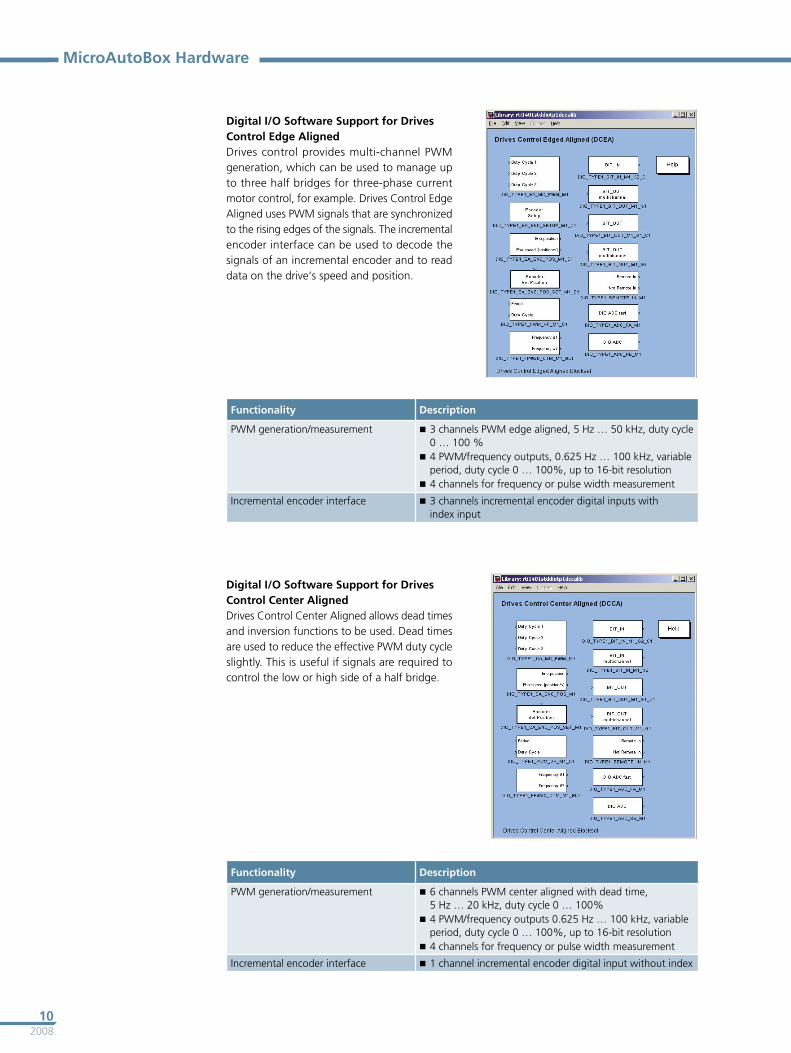
Digital I/O Software Support for Drives Control Edge AlignedDrives control provides multi-channel PWM generation, which can be used to manage up to three half bridges for three-phase current motor control, for example. Drives Control Edge Aligned uses PWM signals that are synchronized to the rising edges of the signals. The incremental encoder interface can be used to decode the signals of an incremental encoder and to read data on the drive‘s speed and position.
Functionality Description
PWM generation/measurement 3 channels PWM edge aligned, 5 Hz … 50 kHz, duty cycle 0 … 100 %
4 PWM/frequency outputs, 0.625 Hz … 100 kHz, variable period, duty cycle 0 … 100%, up to 16-bit resolution
4 channels for frequency or pulse width measurement
Incremental encoder interface 3 channels incremental encoder digital inputs with index input
Digital I/O Software Support for Drives Control Center AlignedDrives Control Center Aligned allows dead times and inversion functions to be used. Dead times are used to reduce the effective PWM duty cycle slightly. This is useful if signals are required to control the low or high side of a half bridge.
Functionality Description
PWM generation/measurement 6 channels PWM center aligned with dead time, 5 Hz … 20 kHz, duty cycle 0 … 100%
4 PWM/frequency outputs 0.625 Hz … 100 kHz, variable period, duty cycle 0 … 100%, up to 16-bit resolution
4 channels for frequency or pulse width measurement
Incremental encoder interface 1 channel incremental encoder digital input without index
112008
MicroAutoBox
Customer-Specific MicroAutoBox
I/O SpecificationsdSPACE offers engineering services to adapt the I/O and signal conditioning of MicroAutoBox to your specifications. As regards I/O, dSPACE offers predeveloped, verified designs that can easily be integrated in MicroAutoBox. In general, these modules do not have to be modified to suit your application, which saves development time and reduces engineering costs. The same I/O modules can of course be integrated several times. dSPACE will also include the I/O circuit designs you provide, such as a company-specific CAN controllers, ASIC, or plug-on devices, and also design new circuits according to your speci-fications.
Signal ConditioningThe signal conditioning portion of MicroAuto-Box can also be adapted to your requirements. Engineering service is available for integrating filter circuits, amplifiers and high-current high-side/low-side drivers. Since the requirements regarding signal conditioning vary with custom-er’s needs, this segment is fully customer-specific. And if you want to include your own concepts, dSPACE will integrate your designs in the board layout. You can even completely design the segment yourself.For further signal conditioning options, please see our RapidPro hardware.
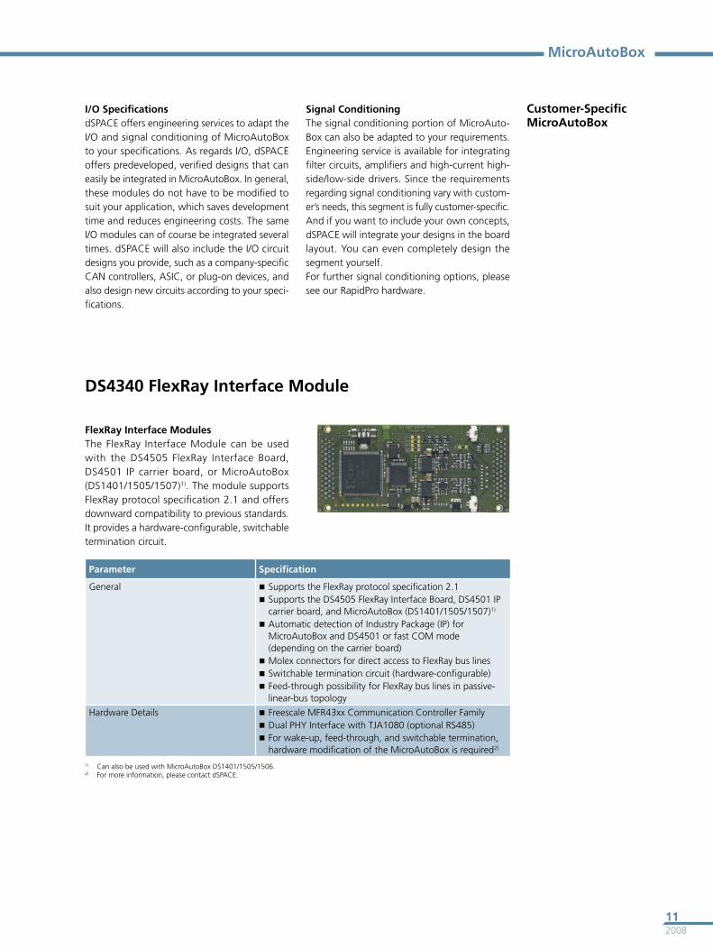
DS4340 FlexRay Interface Module
FlexRay Interface ModulesThe FlexRay Interface Module can be used with the DS4505 FlexRay Interface Board, DS4501 IP carrier board, or MicroAutoBox (DS1401/1505/1507)1). The module supports FlexRay protocol specification 2.1 and offers downward compatibility to previous standards. It provides a hardware-configurable, switchable termination circuit.
Parameter Specification
General Supports the FlexRay protocol specification 2.1 Supports the DS4505 FlexRay Interface Board, DS4501 IP
carrier board, and MicroAutoBox (DS1401/1505/1507)1)
Automatic detection of Industry Package (IP) for MicroAutoBox and DS4501 or fast COM mode (depending on the carrier board)
Molex connectors for direct access to FlexRay bus lines Switchable termination circuit (hardware-configurable) Feed-through possibility for FlexRay bus lines in passive-
linear-bus topology
Hardware Details Freescale MFR43xx Communication Controller Family Dual PHY Interface with TJA1080 (optional RS485) For wake-up, feed-through, and switchable termination,
hardware modification of the MicroAutoBox is required2)
1) Can also be used with MicroAutoBox DS1401/1505/1506.2) For more information, please contact dSPACE.
01/2
008
© C
opyr
ight
200
8 by
dSP
AC
E G
mbH
. All
right
s re
serv
ed. W
ritte
n pe
rmis
sion
is r
equi
red
for
repr
oduc
tion
of a
ll or
par
ts o
f th
is p
ublic
atio
n. T
he s
ourc
e m
ust
be s
tate
d in
any
suc
h re
prod
uctio
n.dS
PAC
E is
con
tinua
lly im
prov
ing
its p
rodu
cts
and
rese
rves
the
rig
ht t
o al
ter
the
spec
ifica
tions
of
the
prod
ucts
con
tain
ed w
ithin
thi
s pu
blic
atio
n at
any
tim
e w
ithou
t no
tice.
Br
and
nam
es o
r pr
oduc
t na
mes
are
tra
dem
arks
or
regi
ster
ed t
rade
mar
ks o
f th
eir
resp
ectiv
e co
mpa
nies
or
orga
niza
tions
.
dSPACEwww.dspace.com
France
dSPACE Sarl Parc Burospace Bâtiment 20 Route de la Plaine de Gisy91573 Bièvres CedexTel.: +33 1 6935 5060 Fax: +33 1 6935 5061 [email protected]
USA and Canada
dSPACE Inc.50131 Pontiac TrailWixom . MI . USA 48393-2020 Tel.: +1 248 295 4700Fax: +1 248 295 [email protected]
United Kingdom
dSPACE Ltd. Unit B7 . Beech HouseMelbourn Science ParkMelbourn Hertfordshire . SG8 6HBTel.: +44 1763 269 020Fax: +44 1763 269 [email protected]
Japan
dSPACE Japan K.K.10F Gotenyama Trust Tower4-7-35 Kitashinagawa Shinagawa-kuTokyo 140-0001Tel: +81 3 5798 5460Fax: +81 3 5798 5464 [email protected]
Headquarters in Germany
dSPACE GmbH Technologiepark 25 33100 PaderbornTel.: +49 5251 16 38-0 Fax: +49 52 51 6 65 29 [email protected]