Embed Size (px)
Citation preview
Portable Bedside Capnograph/Pulse Oximeter
Service Manual
CI05225E
Notice: Purchase of this instrument confers no express or implied license under any Oridion Medical patent or Nellcor Puritan Bennett patent to use the instrument with any accessory that is not manufactured or licensed by Oridion Medical 1987 Ltd. Capnography is covered by one or more of the following United States patents: 6,491,643; 6,656,127; 6,168,958; 5,300,859 and 4,755,675 and their foreign equivalents. この製品は、次の日本における特許、1980816と海外での同等のものによって保護されて
居ります。 Microstream® and FilterLine® are registered trademarks and Smart CapnoLine™, CapnoLine™, Smart BiteBloc™ and NIV Line™ are trademarks of Oridion Medical 1987 Ltd. Nellcor Puritan Bennett Incorporated is an affiliate of Tyco Healthcare. The following are trademarks of Nellcor Puritan Bennett Incorporated: Oxiband®; Durasensor®; OxiCliq®; Dura-Y®; and OXIMAX®. Pulse Oximetry is covered by one or more of the following US patents and foreign equivalents: 4,802,486; 4,869,254; 4,928,692; 4,934,372; 5,078,136; 5,485,847; 5,743,263; 5,865,736; 6,035,223; 6,298,252; 6,463,310; 6,591,123; 6,675,031; 6,708,049; 6,801,797; Re 35,122.
TABLE OF CONTENTSList of FiguresList of Tables
Section 1: Introduction........................................................................ 1-11.1 Manual Overview ............................................................... 1-11.2 Warnings, Cautions, and Notes ......................................... 1-1
1.2.1 Warning.............................................................. 1-11.2.2 Caution............................................................... 1-11.2.3 Note.................................................................... 1-1
1.3 Product Description ........................................................... 1-2Section 2: Required Equipment.......................................................... 2-1
2.1 Required Equipment .......................................................... 2-1Section 3: Cleaning ........................................................................... 3-1
3.1 Cleaning ........................................................................... 3-13.1.1 Procedure........................................................... 3-1
Section 4: Service Mode...................................................................... 4-14.1 Introduction ........................................................................ 4-14.2 Service Level 1 .................................................................. 4-1
4.2.1 Information Screen............................................. 4-14.2.2 Event Messages Screen .................................... 4-14.2.3 Interface Test Screen......................................... 4-24.2.4 Accessing Service Mode and Service Level 1 ... 4-3
4.3 Service Level 2 .................................................................. 4-54.3.1 Default Alarm Limits ........................................... 4-74.3.2 Default Settings.................................................. 4-94.3.3 Flow Calibration ............................................... 4-10
Section 5: Troubleshooting................................................................. 5-15.1 Introduction ........................................................................ 5-15.2 Who Should Perform Repairs ............................................ 5-15.3 Repair Level Supported ..................................................... 5-15.4 How to Use This Section ................................................... 5-15.5 Obtaining Replacement Parts............................................ 5-15.6 Troubleshooting Guide ...................................................... 5-2
Section 6: Flow Calibration Check ..................................................... 6-16.1 Introduction ........................................................................ 6-16.2 Flow Rate Check ............................................................... 6-16.3 Flow Calibration Process ................................................... 6-2
Section 7: Disassembly Guide............................................................ 7-17.1 Introduction ........................................................................ 7-17.2. Opening the Monitor Case................................................. 7-27.3 Replacing the CO2 Board .................................................. 7-47.4 Replacing the SpO2 Board................................................. 7-57.5 Replacing the Pump .......................................................... 7-67.6 Replacing the Flow System ............................................... 7-7
7.6.1 Replacing the lines to the pump......................... 7-87.6.2 Replacing the lines to the solenoid .................... 7-9
7.7 Replacing LCD and LED Display..................................... 7-117.7.1 Replacing the LCD........................................... 7-117.7.2 Replacing the LED Display .............................. 7-11
iii
Table of Contents
7.8 Replacing Housing Components ..................................... 7-127.8.1 ON-OFF Button and Gas Outlet....................... 7-127.8.2 Keypads ........................................................... 7-127.8.3 Front Cover ...................................................... 7-137.8.4 SpO2 Connector Latch, Rear Cover and
SpO2 Insulation Plate....................................... 7-137.9 Updating Software Version .............................................. 7-14
Section 8: Electrical Safety Tests ....................................................... 8-18.1 Electrical Safety Tests ....................................................... 8-1
Section 9: Periodic Maintenance ........................................................ 9-19.1 Periodic Maintenance ........................................................ 9-1
Section 10: Performance Verification............................................... 10-110.1 Flow System Leak Check ................................................ 10-1
10.1.1 Flow System Leak Check Procedure ............... 10-110.2 Performance Verification Procedure................................ 10-2
Section 11: Packing For Shipment ................................................... 11-111.1 General Instructions......................................................... 11-111.2 Packing Monitor in Original Carton .................................. 11-111.3 Packing in a Different Carton........................................... 11-1
Section 12: Specifications................................................................. 12-112.1 Physical ......................................................................... 12-1
12.1.1 Size .................................................................. 12-112.1.2 Weight .............................................................. 12-112.1.3 Noise Emission ................................................ 12-1
12.2 Environmental.................................................................. 12-112.2.1 Temperature..................................................... 12-112.2.2 Relative Humidity ............................................. 12-112.2.3 Pressure and Altitude....................................... 12-1
12.3 Safety Standards ............................................................. 12-112.4 Performance .................................................................... 12-2
12.4.1 Capnograph ..................................................... 12-212.4.2 Pulse Oximeter................................................. 12-3
12.5 Power Specifications ....................................................... 12-412.5.1 External Power Source .................................... 12-412.5.2 Internal Power Source...................................... 12-4
12.6 Components and User interface ...................................... 12-412.6.1 Displays............................................................ 12-412.6.2 Controls and Indicators .................................... 12-412.6.3 Connections ..................................................... 12-4
Section 13: Spare Parts ..................................................................... 13-113.1 Spare Parts List ............................................................... 13-1
Glossary of Terms
iv
Table of Contents
LIST OF FIGURES1-1 Handheld Capnograph/Pulse Oximeter ............................. 1-21-2 LCD Graphic Display and 7 Segment Digital Displays ...... 1-27-1 Removing the Battery Pack ............................................... 7-27-2 Removing Mounting Screws .............................................. 7-37-3 Separating Rear and Front Covers.................................... 7-37-4 Replacing CO2 Board and Housing Components.............. 7-47-5 Replacing SpO2 Board....................................................... 7-57-6 Replacing the Pump .......................................................... 7-67-7 Flow System ...................................................................... 7-77-8 Main Line ........................................................................... 7-87-9 Exhaust Line ...................................................................... 7-87-10 Lines to Solenoid (Zero line, Input line 1, Input line 2........ 7-97-11 Zero line........................................................................... 7-107-12 Replacing LCD and LED Display..................................... 7-117-13 Replacing SpO2 Connector Latch.................................... 7-137-14 Replacing EPROM........................................................... 7-1410-1 Leak Test Jig Connection ................................................ 10-110-2 Initialization Screen.......................................................... 10-210-3 Self-Test Screen .............................................................. 10-210-4 Measuring Mode .............................................................. 10-210-5 Quick Guide ..................................................................... 10-310-6 Connecting the monitor to Printer/PC with
Communication Adapter Kit ............................................. 10-911-1 Packing the Monitor in Original Packing .......................... 11-2
LIST OF TABLES4-1 Accessing Service Mode and Changing Parameter
Settings................................................................... 4-34-2 Accessing Service Level 2................................................. 4-54-3 Changing Default Alarm Limits .......................................... 4-74-4 Changing Default Settings ................................................. 4-94-5 Accessing Flow Calibration.............................................. 4-105-1 Troubleshooting Guide ...................................................... 5-25-2 Advisory Messages Guide ................................................. 5-45-3 Event Messages ................................................................ 5-56-1 Flow Calibration ................................................................. 6-210-1 CO2 Calibration Check..................................................... 10-410-2 Calibration Process.......................................................... 10-610-3 Calibration Process -Troubleshooting.............................. 10-710-4 Plethysmograph Waveform ............................................. 10-810-5 Accessing Monitor’s Print Functions.............................. 10-1013-1 Spare Parts List ............................................................... 13-1
v

Table of Contents
SECTION 1: INTRODUCTION1.1 Manual Overview1.2 Warnings, Cautions, and Notes1.3 Product Description
1.1 MANUAL OVERVIEW
This manual contains information for servicing the handheld capnograph/pulse oximeter (the monitor). Only authorized service personnel should service this product. The Handheld Capnograph/Pulse Oximeter Operator’s Manual (the operator’s manual) is an integral part of the service procedures. Before servicing the monitor, read the operator’s manual carefully for a thorough understanding of how to operate the unit.
Only use the tools and test equipment as specified in this manual. Only use original spare parts available from your local distributor.
Warning: Incorrect procedures may harm the patient, or damage the monitor.
1.2 WARNINGS, CAUTIONS, AND NOTES
1.2.1 Warning
A warning precedes an action that may result in injury or death to the patient or user. Warnings are boxed and highlighted in boldface type.
1.2.2 Caution
A caution precedes an action that may result in damage to, or malfunction of, the monitor. Cautions are highlighted in boldface type.
1.2.3 Note
A note gives information that requires special attention.
1-1

Section 1: Introduction
1.3 PRODUCT DESCRIPTION
The handheld capnograph/pulse oximeter is used to continuously monitor end-tidal carbon dioxide (EtCO2), respiratory rate, oxygen saturation (SpO2), and pulse rate. The monitor is for attended monitoring only and must be used in the continuous presence of a qualified healthcare provider. The monitor can be used on adult, pediatric, and infant/neonatal patients. It is intended for use where continuous, noninvasive monitoring of these parameters is desired, including hospital and mobile use (when protected from excessive moisture such as direct rainfall). The monitor operates on AC power or a rechargeable Nickel Metal Hydride battery pack.
Figure 1-1: Handheld Capnograph/Pulse Oximeter
The monitor is operated using a four-key keypad. Measurements are displayed on the front panel on the 7-segment LED digital displays (LED) and on the LCD graphic display (LCD) as shown in Figure 1-2. Refer to the operator’s manual for complete operating instructions.
Figure 1-2: LCD Graphic Display and 7-Segment Digital Displays
1-2
SECTION 2: REQUIRED EQUIPMENT2.1 Required Equipment
2.1 REQUIRED EQUIPMENT
You will need the following equipment to disassemble, replace parts, check, adjust, or calibrate the monitor.
For disassembly and replacement:
• Phillips-head screwdriver (medium)
• Flat-head screwdriver (small)
• IC Extractor for PLCC socket
• Threadlocker glue e.g. Loctite® 222 super screw lock
For checks, adjustments and calibration:
• Calibration Gas (5% CO2 in air)
• FilterLine or FilterLine H and a connecting means
• DS-100A - OXIMAX Durasensor®, Nellcor
• Leak Test Jig
• Vacuum manometer with a range of 0-500 mBar e.g. MPL-3200-DM, Digital Manometer MicroPneumatic Logic, Inc.
• Communication Adapter Kit (only necessary to verify print functions)
• Seiko DPU-414 printer (only necessary to verify print functions)
• External power supply
• Handheld Capnograph/Pulse Oximeter Operator’s Manual
• Flow Meter (range 0-50 ml/min) e.g. Top Track Mass Flow Meter, model: 822-13-OV1-PV1-V1, Sierra Instruments, Inc.
Warning: Observe ESD (electrostatic discharge) precautions when handling, adjusting or performing any procedure with the monitor’s internal components.
2-1
SECTION 3: CLEANING3.1 Cleaning
3.1 CLEANING
Always clean the outer surface of the monitor before servicing.
Warning: Always wear latex or surgical gloves when cleaning or servicing the monitor after hospital use.
Warning: Do not allow liquids to drip inside the housing.
Warning: Do not clean internal components.
Warning: Do not use preparations based on: phenols, halogen producing compounds, strong organic acids, or oxygen producing compounds.
3.1.1 Procedure
1. Unplug the unit from AC power.
2. With a damp cloth, gently wipe the outer case of the monitor with a disinfectant based on aldehyde, alcohol or quaternary ammonium producing compounds.
3-1
SECTION 4: SERVICE MODE4.1 Introduction4.2 Service Level 1 4.3 Service Level 2
4.1 INTRODUCTION
The monitor supports a service mode built into the instrument’s firmware. To access the service mode, refer to Table 4-1: "Accessing Service Mode and Changing Parameter Settings".
The architecture of the monitor’s service mode divides the service mode into two levels as described in the sections below.
• Service Level 1
• Service Level 2
4.2 SERVICE LEVEL 1
The Service Level 1 provides information and tools on three service screens to test and calibrate specific functions without disassembling the monitor.
• Information Screen
• Event Messages Screen
• Interface Test Screen
From these display screens the service technician can check the operating hours counter and event messages, test the Human Interface functions (HMI), set the light detection threshold, adjust the LCD contrast middle point and do a calibration check and a calibration process, if necessary. Refer to Table 4-1: "Accessing Service Mode and Changing Parameter Settings".
4.2.1 Information Screen
The information screen displays the monitor’s main board serial number, the number of operating hours, and the SpO2 and CO2 boards’ software versions.
4.2.2 Event Messages Screen
The monitor automatically performs a series of built-in tests (BITs) at start-up and during operation to check sub-systems and modules for errors. The event messages screen lists the last five event messages, the time each occurred relative to the unit’s operating hours, and a recommended service action. There are three event messages and each has a specific response as follows:
Event Message: Action:
CO2 board Replace CO2 boardSpO2 board Replace SpO2 boardFlow Replace CO2 board
4-1
Section 4: Service Mode
Note: To exit the service mode and save event messages, turn off the monitor. Event messages will be erased when exiting the service mode by a long press of .
4.2.3 Interface Test Screen
The interface test screen shows four parameters (listed below) that provide tools for the user to test, adjust, and calibrate the unit’s interfacing systems.
• HMI Test
• Light Detector
• Contrast Cal. (Calibration)
• CO2 Calib. (Calibration)
4.2.3.1 HMI Test
When the HMI Test is turned on, the monitor performs a self-test of the following sub-systems:
• Buzzer (sounds for one second)
• LCD graphic display (screen shows a checkerboard pattern)
• 7-segment digital display (8s scroll left to right)
• Alarm bar (lights red, yellow, off)
• Backlight (turns on and off)
• Alarm silence indicator (light turns on and off)
When the HMI test is completed the status field returns automatically to OFF.
4.2.3.2 Light Detector
The Light Detector parameter allows the service technician to set the threshold value of the phototransistor. The default value is 1 and the range is from 1 to 5 with 1 as the most sensitive (backlight on at all times) and 5 as the least sensitive (backlight off). The threshold value should be set according to the lighting conditions of the working environment. A higher threshold value saves on battery power consumption.
4.2.3.3 Contrast Cal. (calibration)
The Contrast Cal. gives the service technician the option to change the middle point default value of the contrast intensity of the LCD. Refer to Table 4-1: "Accessing Service Mode and Changing Parameter Settings".
4.2.3.4 CO2 Calib. (calibration)
The CO2 Calib. allows the service technician to perform a calibration check and calibration process to ensure the accuracy of the monitor. Section 10: Performance Verification describes the calibration check procedure.
4-2
Section 4: Service Mode
4.2.4 Accessing Service Mode and Service Level 1.
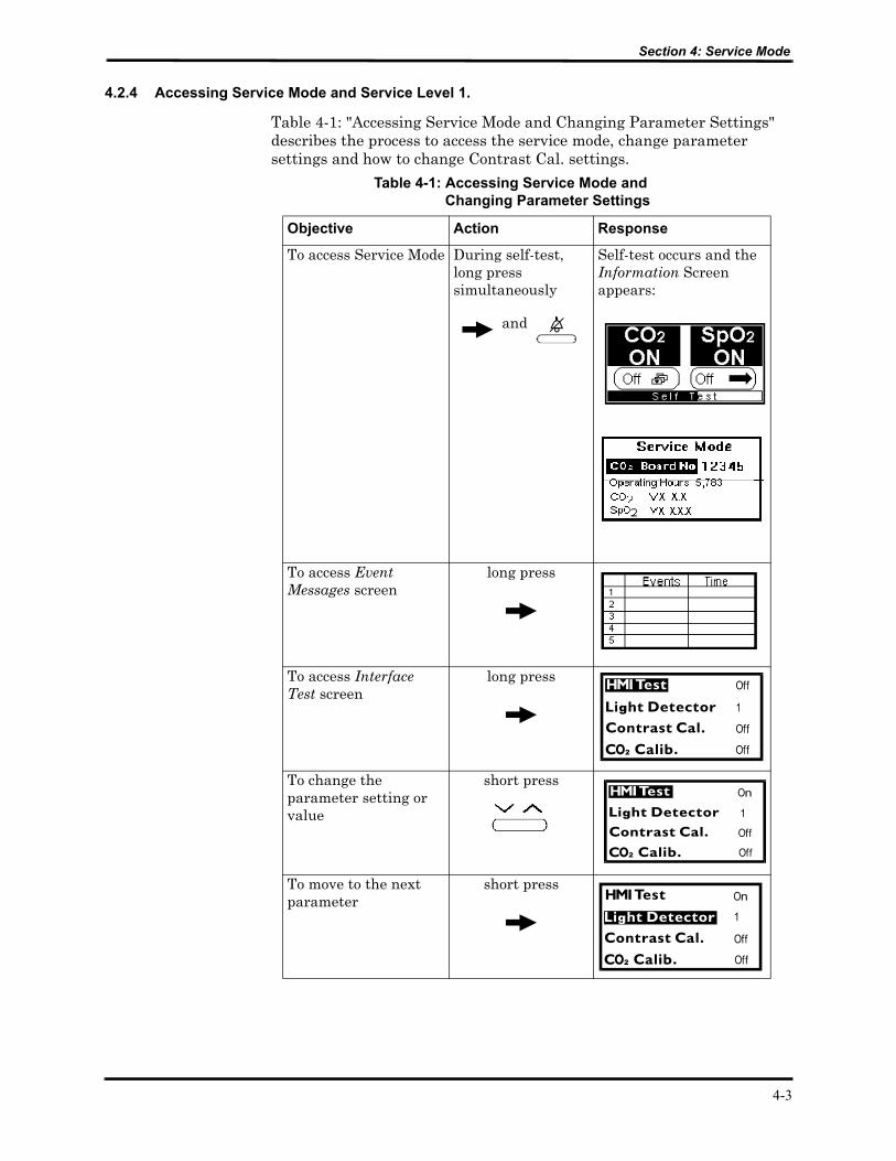
Table 4-1: "Accessing Service Mode and Changing Parameter Settings" describes the process to access the service mode, change parameter settings and how to change Contrast Cal. settings.
Table 4-1: Accessing Service Mode and Changing Parameter Settings
Objective Action Response
To access Service Mode During self-test, long press simultaneously
and
Self-test occurs and the Information Screen appears:
To access Event Messages screen
long press
To access Interface Test screen
long press
To change the parameter setting or value
short press
To move to the next parameter
short press
4-3
Section 4: Service Mode
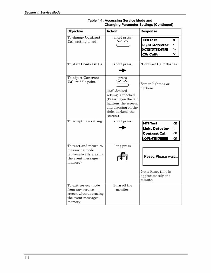
Objective Action Response
To change Contrast Cal. setting to set
short press
To start Contrast Cal. short press “Contrast Cal.” flashes.
To adjust Contrast Cal. middle point
press
until desired setting is reached. (Pressing on the left lightens the screen, and pressing on the right darkens the screen.)
Screen lightens or darkens
To accept new setting short press
To reset and return to measuring mode (automatically erasing the event messages memory)
long press
Note: Reset time is approximately one minute.
To exit service mode from any service screen without erasing the event messages memory
Turn off the monitor.
Table 4-1: Accessing Service Mode and Changing Parameter Settings (Continued)
4-4

Section 4: Service Mode
4.3 SERVICE LEVEL 2
The Service Level 2 gives the service technician tools on three service screens:
• Default Alarm Limits
• Default Settings
• Flow Calibration
To access this service level, the service technician must enter a valid password (1627), refer to Table 4-2: "Accessing Service Level 2".
Note: The password should not be disclosed to avoid unauthorized setting of parameters.
Table 4-2: Accessing Service Level 2
Objective Action Response
To access Service Level 2
After entering the service mode
long press (x3)
Password Screen appears
Enter Password: 1627
Enter the 1st digit short press (right) (x1)
Pressing on the right arrow scrolls the numbers up, the left arrow scrolls the numbers down.
Move to the next digit short press
Enter the 2nd digit short press (right)x6
Repeat the same procedure as above for the next two digits (2, 7).
4-5
Section 4: Service Mode
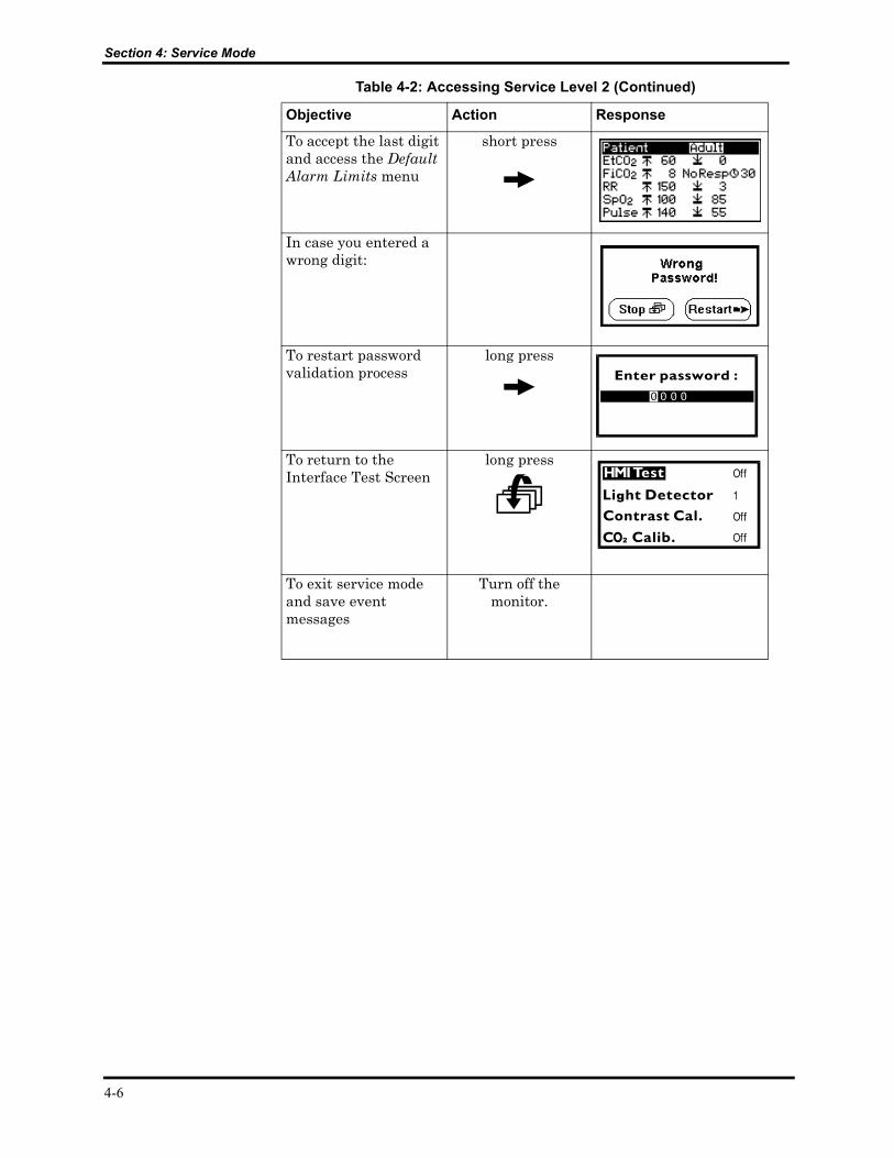
Objective Action Response
To accept the last digit and access the Default Alarm Limits menu
short press
In case you entered a wrong digit:
To restart password validation process
long press
To return to the Interface Test Screen
long press
To exit service mode and save event messages
Turn off the monitor.
Table 4-2: Accessing Service Level 2 (Continued)
4-6
Section 4: Service Mode
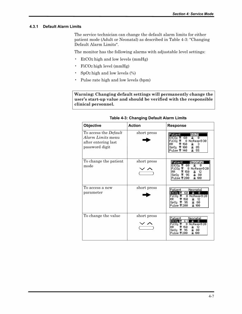
4.3.1 Default Alarm Limits
The service technician can change the default alarm limits for either patient mode (Adult or Neonatal) as described in Table 4-3: "Changing Default Alarm Limits".
The monitor has the following alarms with adjustable level settings:
• EtCO2 high and low levels (mmHg)
• FiCO2 high level (mmHg)
• SpO2 high and low levels (%)
• Pulse rate high and low levels (bpm)
Warning: Changing default settings will permanently change the user’s start-up value and should be verified with the responsible clinical personnel.
Table 4-3: Changing Default Alarm Limits
Objective Action Response
To access the Default Alarm Limits menu after entering last password digit
short press
To change the patient mode
short press
To access a new parameter
short press
To change the value short press
4-7

Section 4: Service Mode
Objective Action Response
To reset to measuring mode (automatically erasing event messages)
long press
then long press
To exit service mode and save event messages
Turn off the monitor.
Table 4-3: Changing Default Alarm Limits (Continued)
4-8
Section 4: Service Mode
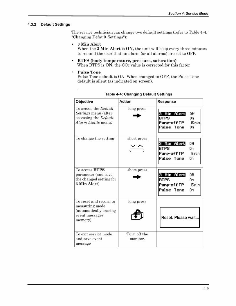
4.3.2 Default Settings
The service technician can change two default settings (refer to Table 4-4: "Changing Default Settings"):
• 3 Min Alert When the 3 Min Alert is ON, the unit will beep every three minutes to remind the user that an alarm (or all alarms) are set to OFF.
• BTPS (body temperature, pressure, saturation)When BTPS is ON, the CO2 value is corrected for this factor
• Pulse Tone Pulse Tone default is ON. When changed to OFF, the Pulse Tone default is silent (as indicated on screen).
. Table 4-4: Changing Default Settings
Objective Action Response
To access the Default Settings menu (after accessing the Default Alarm Limits menu)
long press
To change the setting short press
To access BTPS parameter (and save the changed setting for 3 Min Alert)
short press
To reset and return to measuring mode (automatically erasing event messages memory)
long press
To exit service mode and save event message
Turn off the monitor.
4-9

Section 4: Service Mode
4.3.3 Flow Calibration
The Flow Calibration screen allows the service technician to perform flow calibration after flow adjustment and/or pump or flow system replacement, refer to Table 4-5: "Accessing Flow Calibration"
Note: When changing the pump voltage setting, refer to Section 6: Flow Calibration Check for change guidelines.
Table 4-5: Accessing Flow Calibration
Objective Action Response
To access the Flow Calibration screen
At any screen after the passwordlong press simultaneously
and
To change the parameter setting or value
short press
To move to the next parameter (and save the changed setting)
short press
4-10
SECTION 5: TROUBLESHOOTING5.1 Introduction5.2 Who Should Perform Repairs5.3 Repair Level Supported5.4 How to Use This Section5.5 Obtaining Replacement Parts5.6 Troubleshooting Guide
5.1 INTRODUCTION
This section provides information for troubleshooting the monitor and isolating a failure on the unit.
5.2 WHO SHOULD PERFORM REPAIRS
Only qualified service personnel should remove and replace components of the monitor. If your facility does not have qualified service personnel, contact your local distributor.
5.3 REPAIR LEVEL SUPPORTED
The monitor has the following replaceable components: CO2 board, SpO2 board, Flow System, Pump Assembly, Housing Components, LCD graphic display (LCD), 7-segment LED digital displays (LED display) and Software Assembly.
The procedures for disassembling and replacing the mentioned parts are described in Section 7: Disassembly Guide.
5.4 HOW TO USE THIS SECTION
Failures of the Housing Components; Front Cover, Rear Cover, Gas Outlet, External SpO2 Connector Latch, ON/OFF button and Keypads, are determined by visually inspecting these components for cracks or deformations, and checking for mechanical failures.
Refer to Table 5-1: “Troubleshooting Guide”to isolate failures of the boards, Flow System, Pump Assembly, LCD and LED displays. Once a failure has been isolated, refer to Section 7: Disassembly Guide for instructions for removing and replacing a component of the monitor.
5.5 OBTAINING REPLACEMENT PARTS
Your local distributor provides technical assistance information and replacement parts. Refer to parts by the part name listed in Section 13: Spare Parts.
5-1
Section 5: Troubleshooting
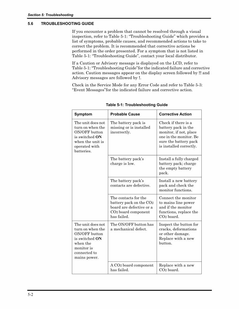
5.6 TROUBLESHOOTING GUIDE
If you encounter a problem that cannot be resolved through a visual inspection, refer to Table 5-1: “Troubleshooting Guide” which provides a list of symptoms, probable causes, and recommended actions to take to correct the problem. It is recommended that corrective actions be performed in the order presented. For a symptom that is not listed in Table 5-1: “Troubleshooting Guide”, contact your local distributor.
If a Caution or Advisory message is displayed on the LCD, refer to Table 5-1: “Troubleshooting Guide”for the indicated failure and corrective action. Caution messages appear on the display screen followed by !! and Advisory messages are followed by !.
Check in the Service Mode for any Error Code and refer to Table 5-3: “Event Messages”for the indicated failure and corrective action.
Table 5-1: Troubleshooting Guide
Symptom Probable Cause Corrective Action
The unit does not turn on when the ON/OFF button is switched ON when the unit is operated with batteries.
The battery pack is missing or is installed incorrectly.
Check if there is a battery pack in the monitor, if not, place one in the monitor. Be sure the battery pack is installed correctly.
The battery pack’s charge is low.
Install a fully charged battery pack; charge the empty battery pack.
The battery pack’s contacts are defective.
Install a new battery pack and check the monitor functions.
The contacts for the battery pack on the CO2 board are defective or a CO2 board component has failed.
Connect the monitor to mains line power and if the monitor functions, replace the CO2 board.
The unit does not turn on when the ON/OFF button is switched ON when the monitor is connected to mains power.
The ON/OFF button has a mechanical defect.
Inspect the button for cracks, deformations or other damage. Replace with a new button.
A CO2 board component has failed.
Replace with a new CO2 board.
5-2

Section 5: Troubleshooting
Symptom Probable Cause Corrective Action
The unit does not turn on when the ON/OFF button is switched ON when the monitor is connected to main lines power.
The wall socket is not receiving power or is defective.
Check the wall socket for power supply or mechanical defects. If necessary, use a different wall socket.
The AC adapter is defective.
Replace with new AC adapter.
A CO2 board component is defective.
Replace with a new CO2 board.
One or more buttons on the upper or lower keypad do not work.
The keypad is defective. Inspect the keypad for cracks, deformations or other damage. Replace with a new keypad.
A CO2 board component has failed.
Replace with a new CO2 board.
No information is displayed on the LCD.
The contrast default value is set too low or high.
Check the contrast value in the Service Mode using the Contrast Cal. option and correct accordingly.
An LCD component has failed.
Replace with a new LCD.
A CO2 board component has failed.
Replace with a new CO2 board.
LCD Backlight does not come on when the unit is placed in a dark environment.
The Power Management option is set at LOW.
Refer to the monitor’s operator’s manual to change the Power Management option to NORMAL or HIGH.
An LCD component has failed.
Replace with a new LCD.
A CO2 board component has failed.
Replace with a new CO2 board.
Table 5-1: Troubleshooting Guide (Continued)
5-3
Section 5: Troubleshooting
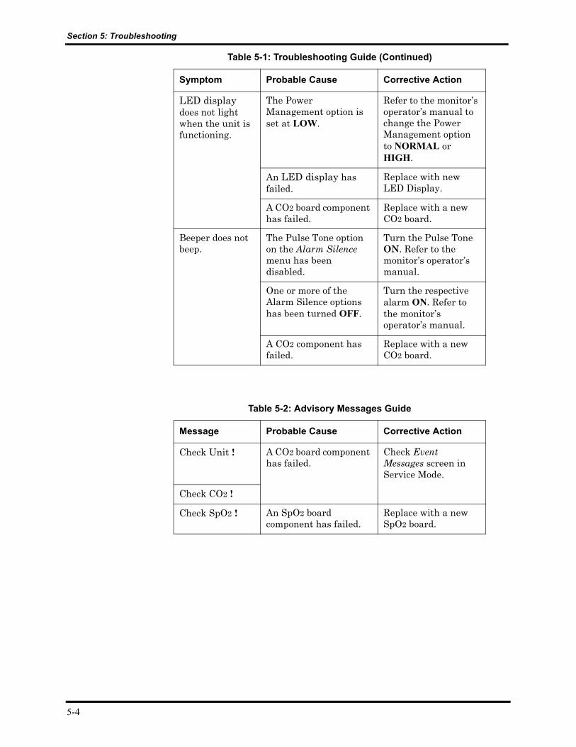
Symptom Probable Cause Corrective Action
LED display does not light when the unit is functioning.
The Power Management option is set at LOW.
Refer to the monitor’s operator’s manual to change the Power Management option to NORMAL or HIGH.
An LED display has failed.
Replace with new LED Display.
A CO2 board component has failed.
Replace with a new CO2 board.
Beeper does not beep.
The Pulse Tone option on the Alarm Silence menu has been disabled.
Turn the Pulse Tone ON. Refer to the monitor’s operator’s manual.
One or more of the Alarm Silence options has been turned OFF.
Turn the respective alarm ON. Refer to the monitor’s operator’s manual.
A CO2 component has failed.
Replace with a new CO2 board.
Table 5-2: Advisory Messages Guide
Message Probable Cause Corrective Action
Check Unit ! A CO2 board component has failed.
Check Event Messages screen in Service Mode.
Check CO2 !
Check SpO2 ! An SpO2 board component has failed.
Replace with a new SpO2 board.
Table 5-1: Troubleshooting Guide (Continued)
5-4
Section 5: Troubleshooting
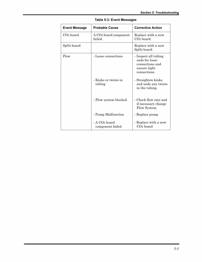
Table 5-3: Event Messages
Event Message Probable Cause Corrective Action
CO2 board A CO2 board component failed.
Replace with a new CO2 board.
SpO2 board Replace with a new SpO2 board.
Flow - Loose connections
- Kinks or twists in tubing
- Flow system blocked
- Inspect all tubing ends for loose connections and ensure tight connections
- Straighten kinks and undo any twists in the tubing.
- Check flow rate and if necessary change Flow System.
- Pump Malfunction - Replace pump
- A CO2 board component failed
- Replace with a new CO2 board
5-5

SECTION 6: FLOW CALIBRATION CHECK6.1 Introduction6.2 Flow Rate Check6.3 Flow Calibration Process
6.1 INTRODUCTION
Perform a Flow Calibration Check after replacing the Flow System and/or Pump. Flow Calibration Check includes Flow Rate Check and Flow Calibration Process.
6.2 FLOW RATE CHECK
To perform the Flow Rate Check, follow the steps below:
1. Connect the FilterLine to the Handheld Capnograph/Pulse Oximeter.
2. Turn on the monitor.
3. Connect the other end of the FilterLine to the Flow meter gas outlet.
4. Access the Flow Calibration screen of the Service Mode, refer to Table 6-1: "Flow Calibration".
5. Check that the Flow Meter reading is 50 ±5 ml/min. (at sea level)
If the Flow Meter reading is 50 ±5 ml/min:
5a Perform Flow Calibration Process, refer to section 6.3 "Flow Calibration Process".
If the Flow Meter reading is not 50 ±5 ml/min:
5b Change the pump voltage value until the flow rate displayed in the flow meter is 50 ±5 ml/min, refer to Section 4: Service Mode, Table 4-5: "Accessing Flow Calibration".
5c Perform Flow Rate Check
5d Perform Flow Calibration Process, section 6.3 "Flow Calibration Process".
If you cannot set the flow rate to 50 ±5 ml/min after adjusting the pump voltage value:
5e Change the Flow System, refer to section 7.6 "Replacing the Flow System".
5f Perform Flow Rate Check
5g Perform Flow Calibration Process.
If after changing the Flow System you still cannot set the flow rate display in the flow meter to 50 ±5 ml/min:
5h Change the Pump, refer to section 7.5 "Replacing the Pump".
5i Perform Flow Rate Check
5j Perform Flow Calibration Process.
6-1
Section 6: Flow Calibration Check
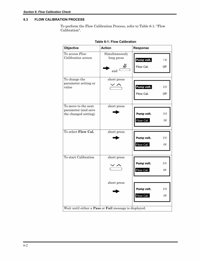
6.3 FLOW CALIBRATION PROCESS
To perform the Flow Calibration Process, refer to Table 6-1: "Flow Calibration".
Table 6-1: Flow Calibration
Objective Action Response
To access Flow Calibration screen
Simultaneously long press
and
To change the parameter setting or value
short press
To move to the next parameter (and save the changed setting)
short press
To select Flow Cal. short press
To start Calibration short press
short press
Wait until either a Pass or Fail message is displayed.
6-2
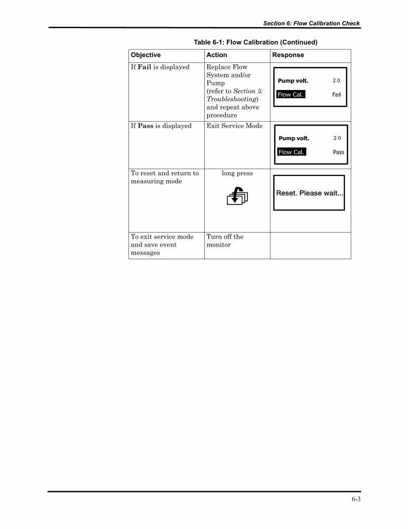
Section 6: Flow Calibration Check
Objective Action Response
If Fail is displayed Replace Flow System and/or Pump (refer to Section 5: Troubleshooting)and repeat above procedure
If Pass is displayed Exit Service Mode
To reset and return to measuring mode
long press
To exit service mode and save event messages
Turn off the monitor
Table 6-1: Flow Calibration (Continued)
Pump volt. 2.0
Pump volt. 2.0
6-3

SECTION 7: DISASSEMBLY GUIDE7.1 Introduction7.2 Opening the Monitor Case7.3 Replacing the CO2 Board7.4 Replacing the SpO2 Board7.5 Replacing the Pump7.6 Replacing the Flow System7.7 Replacing the LCD and LED Display7.8 Replacing the Housing Components7.9 Updating the Software Version
7.1 INTRODUCTION
The monitor can be disassembled and the following components can be replaced:
• CO2 Board
• SpO2 Board
• Pump Assembly
• Flow System
• Housing components
• EPROM
• LCD graphic display (LCD)
• 7-segment LED digital displays (LED Display)
Caution: Observe ESD (electrostatic discharge) precautions when disassembling and reassembling the monitor and when handling any of the components of the monitor.
Use the following procedures to disassemble the monitor and replace parts as needed. Reassemble the monitor in reverse order. The manufacturer recommends that you follow the disassembly procedure in the order presented.
Note: After replacing the Flow System and/or Pump, perform a flow calibration check as described in Section 6: Flow Calibration Check.
Note: After reassembling any part of the monitor, be sure to complete the performance verification as described in Section 10: Performance Verification.
7-1

Section 7: Disassembly Guide
7.2 OPENING THE MONITOR CASE
1. Be sure the monitor is disconnected from mains power and remove the battery pack from the monitor; press the release button at the bottom of the monitor and pull out the battery pack as shown in Figure 7-1: Removing the Battery Pack.
Figure 7-1: Removing the Battery Pack
7-2
Section 7: Disassembly Guide
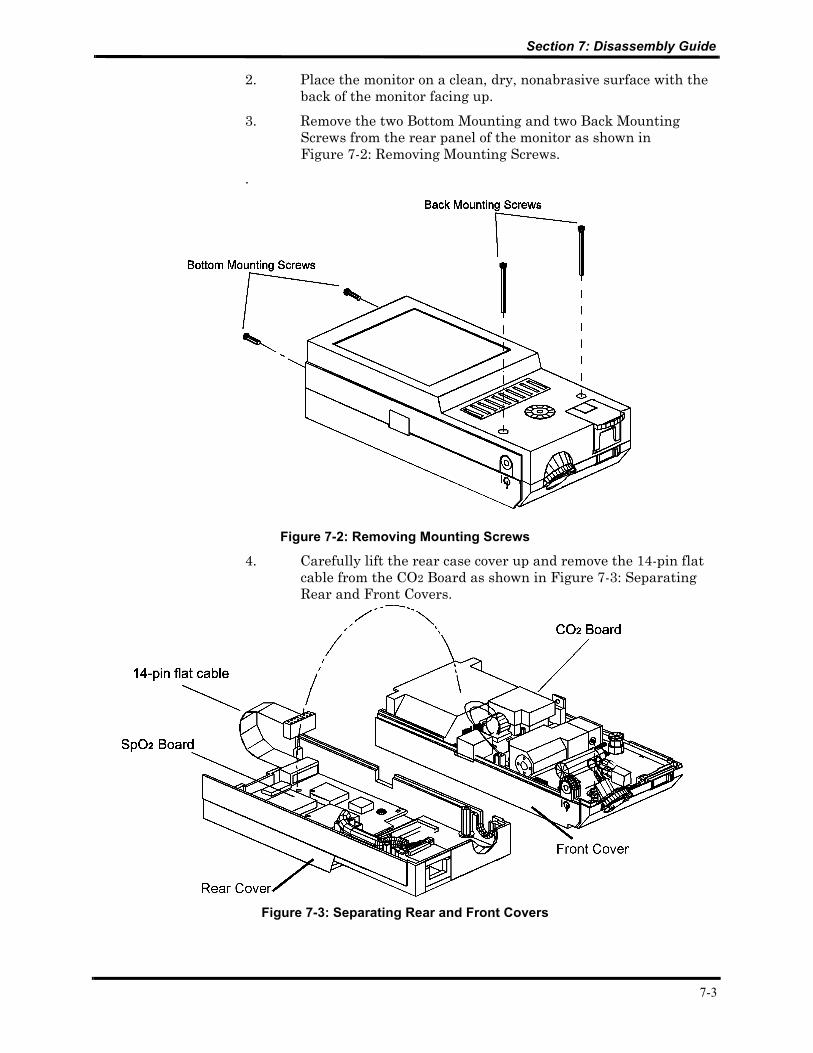
2. Place the monitor on a clean, dry, nonabrasive surface with the back of the monitor facing up.
3. Remove the two Bottom Mounting and two Back Mounting Screws from the rear panel of the monitor as shown in Figure 7-2: Removing Mounting Screws.
.
Figure 7-2: Removing Mounting Screws
4. Carefully lift the rear case cover up and remove the 14-pin flat cable from the CO2 Board as shown in Figure 7-3: Separating Rear and Front Covers.
Figure 7-3: Separating Rear and Front Covers
7-3
Section 7: Disassembly Guide
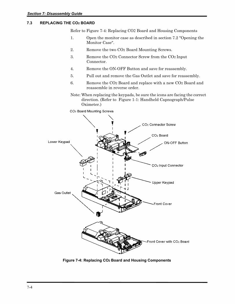
7.3 REPLACING THE CO2 BOARD
Refer to Figure 7-4: Replacing CO2 Board and Housing Components
1. Open the monitor case as described in section 7.2 "Opening the Monitor Case".
2. Remove the two CO2 Board Mounting Screws.
3. Remove the CO2 Connector Screw from the CO2 Input Connector.
4. Remove the ON-OFF Button and save for reassembly.
5. Pull out and remove the Gas Outlet and save for reassembly.
6. Remove the CO2 Board and replace with a new CO2 Board and reassemble in reverse order.
Note: When replacing the keypads, be sure the icons are facing the correct direction. (Refer to Figure 1-1: Handheld Capnograph/Pulse Oximeter.)
Figure 7-4: Replacing CO2 Board and Housing Components
7-4

Section 7: Disassembly Guide
7.4 REPLACING THE SPO2 BOARD (Refer to Figure 7-5: Replacing SpO2 Board.)
1. Open the monitor case as described in section 7.2 "Opening the Monitor Case".
2. Pull out the Internal SpO2 Connector Lock.
3. Remove the three SpO2 Board Mounting Screws and Washers.
4. Remove the SpO2 Board with attached cables and replace with a new SpO2 Board. Be sure to reattach the cables and use the new Internal SpO2 Connector Lock. Be sure the SpO2 Insulation Plate is placed correctly over the three screw mounts.
Caution: When replacing the SpO2 Mounting Screws, be sure you use the plastic washers supplied with the original unit.
Caution: When replacing the SpO2 Board, carefully hand-tighten the Mounting Screws. Overtightening can strip the screw-holes.
Figure 7-5: Replacing SpO2 Board
7-5
Section 7: Disassembly Guide
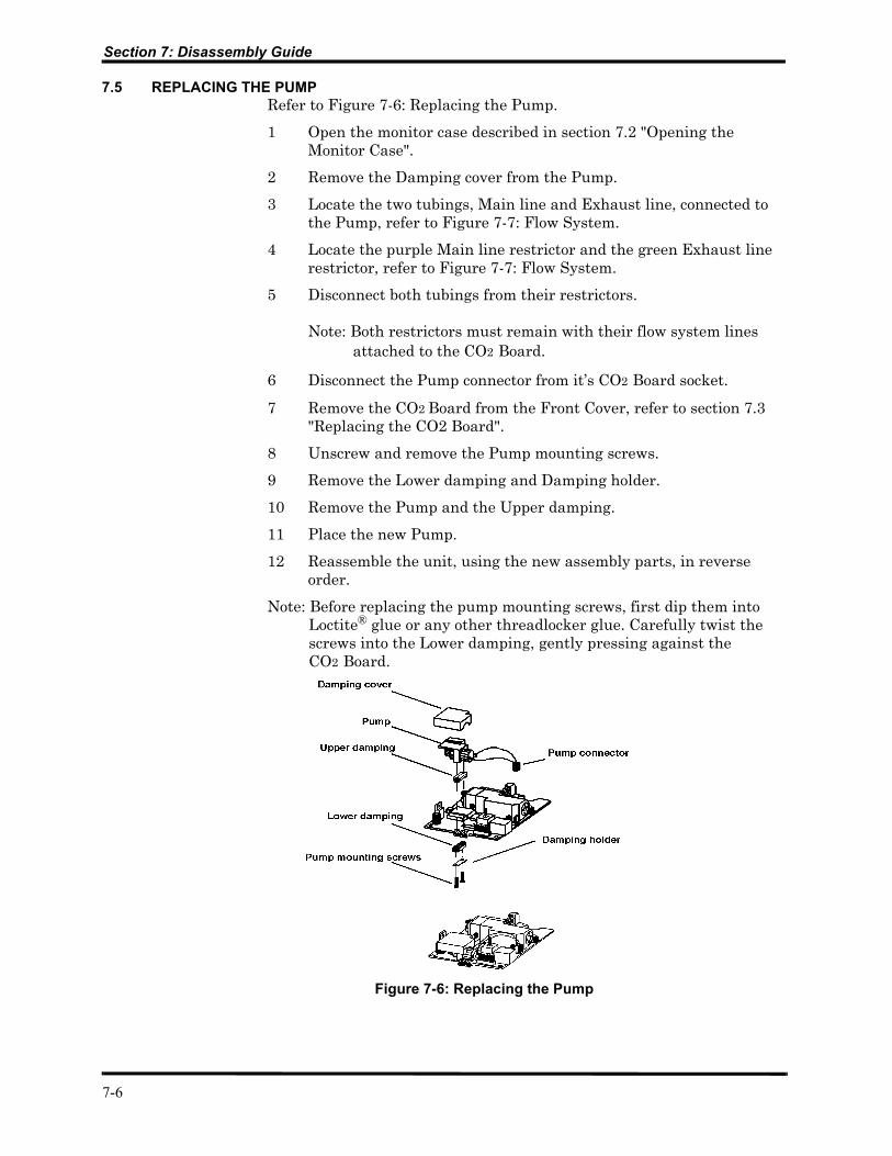
7.5 REPLACING THE PUMPRefer to Figure 7-6: Replacing the Pump.
1 Open the monitor case described in section 7.2 "Opening the Monitor Case".
2 Remove the Damping cover from the Pump.
3 Locate the two tubings, Main line and Exhaust line, connected to the Pump, refer to Figure 7-7: Flow System.
4 Locate the purple Main line restrictor and the green Exhaust line restrictor, refer to Figure 7-7: Flow System.
5 Disconnect both tubings from their restrictors.
Note: Both restrictors must remain with their flow system lines attached to the CO2 Board.
6 Disconnect the Pump connector from it’s CO2 Board socket.
7 Remove the CO2 Board from the Front Cover, refer to section 7.3 "Replacing the CO2 Board".
8 Unscrew and remove the Pump mounting screws.
9 Remove the Lower damping and Damping holder.
10 Remove the Pump and the Upper damping.
11 Place the new Pump.
12 Reassemble the unit, using the new assembly parts, in reverse order.
Note: Before replacing the pump mounting screws, first dip them into Loctite® glue or any other threadlocker glue. Carefully twist the screws into the Lower damping, gently pressing against the CO2 Board.
Figure 7-6: Replacing the Pump
7-6
Section 7: Disassembly Guide
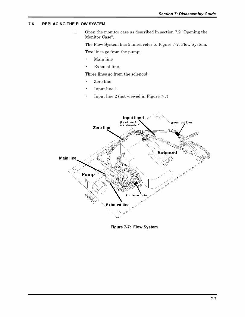
7.6 REPLACING THE FLOW SYSTEM
1. Open the monitor case as described in section 7.2 "Opening the Monitor Case".
The Flow System has 5 lines, refer to Figure 7-7: Flow System.
Two lines go from the pump:
• Main line
• Exhaust line
Three lines go from the solenoid:
• Zero line
• Input line 1
• Input line 2 (not viewed in Figure 7-7)
Figure 7-7: Flow System
7-7

Section 7: Disassembly Guide
7.6.1 Replacing the lines to the pump
7.6.1.1 Replacing the Main line (Refer to Figure 7-8: Main line and Figure 7-9: Exhaust line)
1. Locate the purple restrictor.2. Carefully disconnect the Main line from the tubing
connected to the Pump, leaving the purple restrictor on the Main line.
3. Remove the tubing from the Sensor.4. Remove the tubing from the Pressure sensor.5. Reassemble the new Main line in reverse order.
Note: In order to fit the Main line on the board without twists and kinks, coil the tubing around the Pressure sensor.
7.6.1.2 Replacing the Exhaust line (Refer to Figure 7-9: Exhaust line)
1. Locate the green restrictor.
2. Carefully disconnect the Exhaust line, at the green restrictor, from the tubing connected to the pump. Leave the green restrictor on the Exhaust line.
3. Reassemble the new Exhaust line in reverse order.
Figure 7-8: Main line
Figure 7-9: Exhaust line
7-8

Section 7: Disassembly Guide
7.6.2 Replacing the lines to the solenoidRefer to:Figure 7-10: Lines to Solenoid (Zero line, Input line 1, Input line 2)
7.6.2.1 Removing the lines to the solenoid
1. Carefully disconnect the Zero line from the solenoid.
Warning: The scrubber on the Zero line is filled with a lithium based compound. Follow local governing ordinances for disposal.
2. Remove Input line 1 from the solenoid connector and the other end from the FilterLine input connector.
3. Remove Input line 2 from the solenoid connector and the other end from the sensor connector.
Figure 7-10: Lines to Solenoid (Zero line, Input line 1, Input line 2)
7-9

Section 7: Disassembly Guide
7.6.2.2 Reassembly of the lines to SolenoidRefer to Figure 7-10: Lines to Solenoid (Zero line, Input line 1, Input line 2) and Figure 7-11: Zero line
1. Connect the new Input line1 to the line 1 solenoid connector. 2. Connect the new Input line 2 to the line 2 solenoid connector.3. Bring the Input line 2 tubing over Input line 1, and connect to
the sensor connector.4. Lead the Input line 1 under the FRS cables (connected to the
FilterLine input connector, not viewed in Figure 7-10) and connect to the FilterLine input connector.
5. Connect the Zero line to the Zero line solenoid connector. Place the scrubber close to the pump under the coiled Main line tubing (not viewed in Figure 7-11: Zero line) around the pressure sensor.
Figure 7-11: Zero line
7-10

Section 7: Disassembly Guide
7.7 REPLACING LCD AND LED DISPLAY(Refer to Figure 7-12: Replacing LCD and LED display)
7.7.1 Replacing the LCD
1. Remove the CO2 Board as described in Figure 7-4: Replacing CO2 Board and Housing Components.
2. Unscrew and remove the four LCD mounting screws.
3. Carefully remove the LCD and replace with a new LCD.
7.7.2 Replacing the LED Display
1. Remove the CO2 Board as described in section 7.3 "Replacing the CO2 Board".
2. Carefully remove the faulty LED Display from its socket and replace with a new LED Display. Note the correct orientation of the LED Display when replacing it.
Figure 7-12: Replacing LCD and LED display
7-11

Section 7: Disassembly Guide
7.8 REPLACING HOUSING COMPONENTS
The Housing kit includes the following replaceable components:
• Front Cover• Rear Cover• ON-OFF Button• Upper Keypad (Alarm Silence/Alarm Silence Menu Button and
Contrast/Value Change Button)• Lower Keypad (Event/Home Button and Next/Menu Button)• Gas Outlet• SpO2 Insulation Plate• External SpO2 Connector Latch• Internal SpO2 Connector Lock• Screws• Washers
Note: When reassembling the monitor after replacing any part, be sure to follow the disassembly steps in reverse order.
7.8.1 ON-OFF Button and Gas Outlet(Refer to Figure 7-4: Replacing CO2 Board and Housing Components)
1. Open the monitor as described in section 7.2 "Opening the Monitor Case".
2. Remove the Gas Outlet from the tubing and replace with a new Gas Outlet.
3. Remove the ON-OFF Button from the CO2 board as described in section 7.3 "Replacing the CO2 Board", and replace with a new button.
7.8.2 Keypads (Refer to Figure 7-4: Replacing CO2 Board and Housing Components)
1. Open the monitor as described in section 7.2 "Opening the Monitor Case".
2. Remove the CO2 Board as described in section 7.3 "Replacing the CO2 Board".
3. Remove the old keypad. When replacing the new keypad, be sure the icons are facing the correct direction. (Refer to Figure 1-1: Handheld Capnograph/Pulse Oximeter.)
7-12
Section 7: Disassembly Guide
7.8.3 Front Cover (Refer to Figure 7-4: Replacing CO2 Board and Housing Components)
1. Open the monitor as described in section 7.2 "Opening the Monitor Case".
2. Remove the CO2 Board as described in section 7.3 "Replacing the CO2 Board".
3. Remove the keypad and ON-OFF Button. Place them in the new Front Cover. When replacing the keypad, be sure the icons are facing the correct direction. (Refer to Figure 1-1: Handheld Capnograph/Pulse Oximeter.)
4. Place the CO2 board in the new cover.
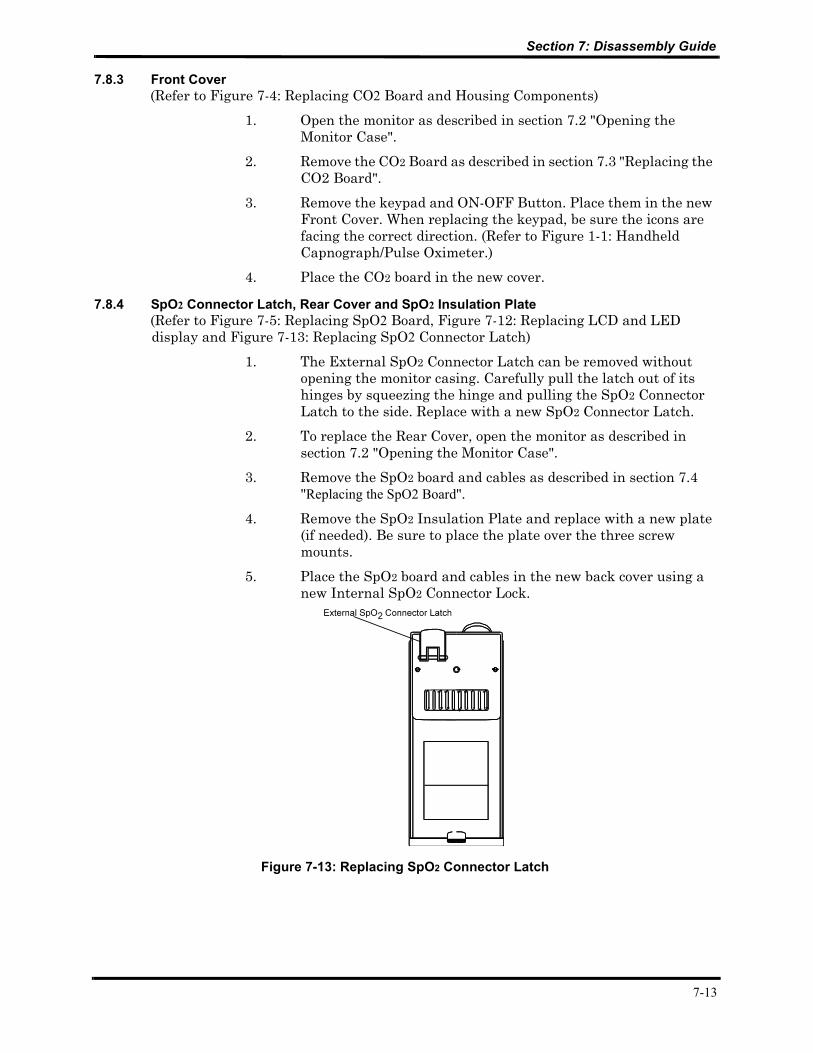
7.8.4 SpO2 Connector Latch, Rear Cover and SpO2 Insulation Plate (Refer to Figure 7-5: Replacing SpO2 Board, Figure 7-12: Replacing LCD and LED display and Figure 7-13: Replacing SpO2 Connector Latch)
1. The External SpO2 Connector Latch can be removed without opening the monitor casing. Carefully pull the latch out of its hinges by squeezing the hinge and pulling the SpO2 Connector Latch to the side. Replace with a new SpO2 Connector Latch.
2. To replace the Rear Cover, open the monitor as described in section 7.2 "Opening the Monitor Case".
3. Remove the SpO2 board and cables as described in section 7.4 "Replacing the SpO2 Board".
4. Remove the SpO2 Insulation Plate and replace with a new plate (if needed). Be sure to place the plate over the three screw mounts.
5. Place the SpO2 board and cables in the new back cover using a new Internal SpO2 Connector Lock.
Figure 7-13: Replacing SpO2 Connector Latch
7-13
Section 7: Disassembly Guide
7.9 UPDATING SOFTWARE VERSION
Warning: Observe ESD (electrostatic discharge) precautions when disassembling and reassembling the monitor and when handling any of the components of the monitor.
1. Open the monitor as described in section 7.2 "Opening the Monitor Case".
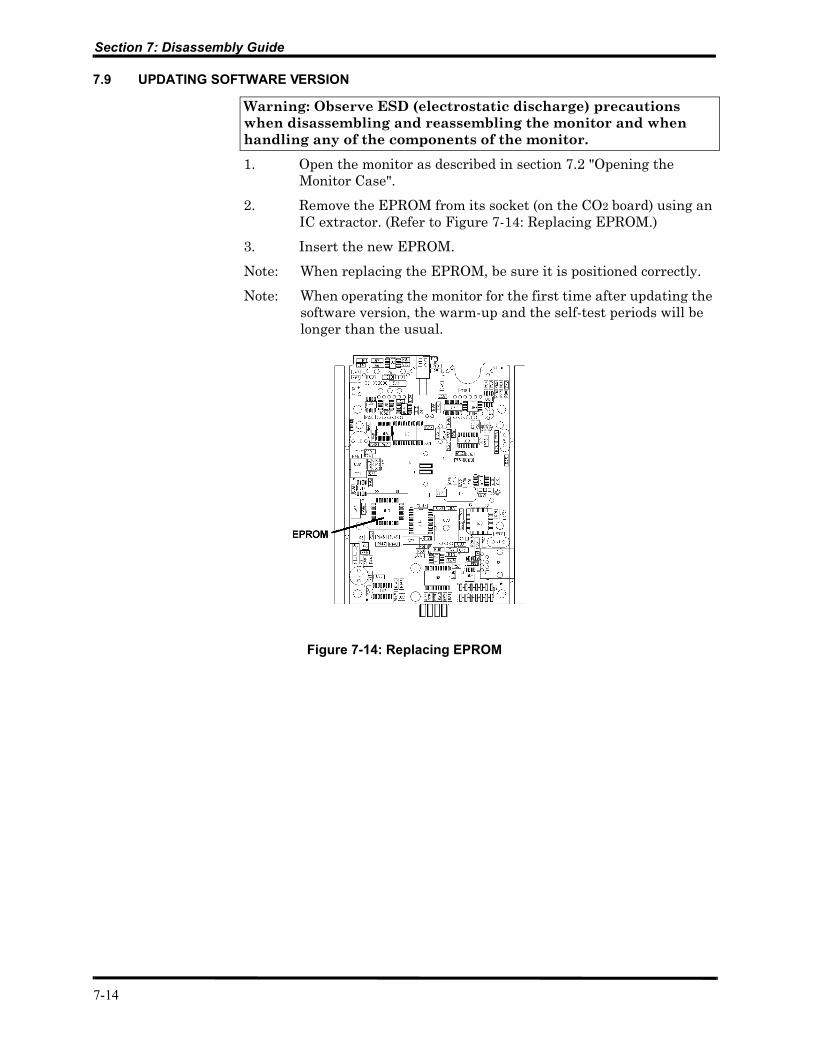
2. Remove the EPROM from its socket (on the CO2 board) using an IC extractor. (Refer to Figure 7-14: Replacing EPROM.)
3. Insert the new EPROM.
Note: When replacing the EPROM, be sure it is positioned correctly.
Note: When operating the monitor for the first time after updating the software version, the warm-up and the self-test periods will be longer than the usual.
Figure 7-14: Replacing EPROM
7-14

SECTION 8: ELECTRICAL SAFETY TESTS8.1 Electrical Safety Tests
8.1 ELECTRICAL SAFETY TESTS
Do not return the monitor to the user until the conditions are met in the following “Warning” statement.
Warning: After servicing the monitor, always verify product performance per the procedures in Section 10: Performance Verification and perform any safety tests required by local regulatory bodies or mandated by your institution.
8-1
9-1
SECTION 9: PERIODIC MAINTENANCE9.1 Periodic Maintenance
9.1 PERIODIC MAINTENANCE
Periodic maintenance is recommended according to operating hours (refer to section 4.2 "Service Level 1"):
The Pump and Flow System should be replaced every 7,000 operating hours.
For replacing the pump, refer to section 7.5 "Replacing the Pump".
For replacing the flow system, refer to section 7.6 "Replacing the Flow System".
The monitor should be returned to the manufacturer for periodic maintenance every 21,000 operating hours.
SECTION 10: PERFORMANCE VERIFICATION10.1 Flow System Leak Check10.2 Performance Verification Procedure
The performance of the monitor must be verified after all service procedures. Perform all procedures in this section to verify the correct functioning of the monitor.
10.1 FLOW SYSTEM LEAK CHECK
Perform the Flow System Leak Check after all service procedures described in this manual.
10.1.1 Flow System Leak Check Procedure
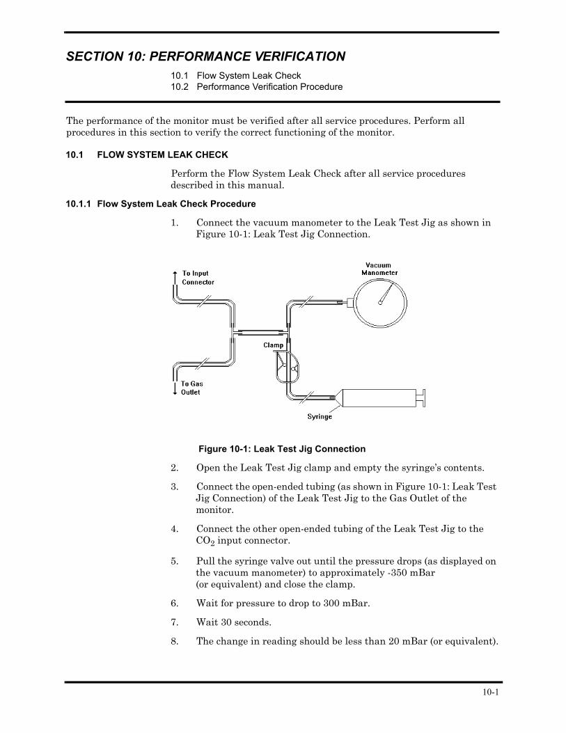
1. Connect the vacuum manometer to the Leak Test Jig as shown in Figure 10-1: Leak Test Jig Connection.
Figure 10-1: Leak Test Jig Connection
2. Open the Leak Test Jig clamp and empty the syringe’s contents.
3. Connect the open-ended tubing (as shown in Figure 10-1: Leak Test Jig Connection) of the Leak Test Jig to the Gas Outlet of the monitor.
4. Connect the other open-ended tubing of the Leak Test Jig to the CO2 input connector.
5. Pull the syringe valve out until the pressure drops (as displayed on the vacuum manometer) to approximately -350 mBar (or equivalent) and close the clamp.
6. Wait for pressure to drop to 300 mBar.
7. Wait 30 seconds.
8. The change in reading should be less than 20 mBar (or equivalent).
10-1

Section 10: Performance Verification
9. If the reading drops more than 20 mBar, there is a leak in the flow system.
• Open the unit.
• Check for loose fittings and if any are found, reconnect them.
• Repeat the above process (steps 1-8).
• If the reading continues to show more than 20 mBar, replace the Flow System, refer to section 7.6 "Replacing the Flow System".
10.2 PERFORMANCE VERIFICATION PROCEDURE
Verify the performance of the monitor using the following procedure.
1. Connect the monitor to main power using the AC adapter.
2. Connect the FilterLine and the DS-100A - Durasensor® to the monitor.
3. Turn ON the monitor.
4. The initialization screen appears. (Refer to Figure 10-2: Initialization Screen.)
5. Verify that an audio tone sounds. This verifies proper operation of the Alarm interfacing. Check that the LEDs on the alarm bar turn red, yellow and then off. The LED display shows 8s moving from left to right.
6. As the monitor continues to test its internal subsystems, the Self-Test Screen appears. (Refer to Figure 10-3: Self-Test Screen.).
7. After the Self-test, the monitor automatically goes to Measuring Mode. The message CO2 Warmup appears on the Silent Advisory Message area. (Refer to Figure 10-4: Measuring Mode.)
Note: If BTPS is on, the message will read BTPS ON-Ready
8. After CO2 Warmup, verify that the message changes to Ready.
9. Disconnect the FilterLine and verify that the message FilterLine is displayed on the Silent Advisory Message Area and verify that the pump stops.
Figure 10-2: Initialization Screen
Figure 10-3: Self-Test Screen
Figure 10-4: Measuring Mode
10-2
Section 10: Performance Verification
10. Reconnect the FilterLine and verify that the message FilterLine disappears and the pump is operating.
11. Disconnect the DS-100A - OXIMAX Durasensor® and verify that the message SpO2 Sensor is displayed in the Silent Advisory Message area.
12. Reconnect the DS-100A - OXIMAX Durasensor® and verify that the message SpO2 Sensor disappears.
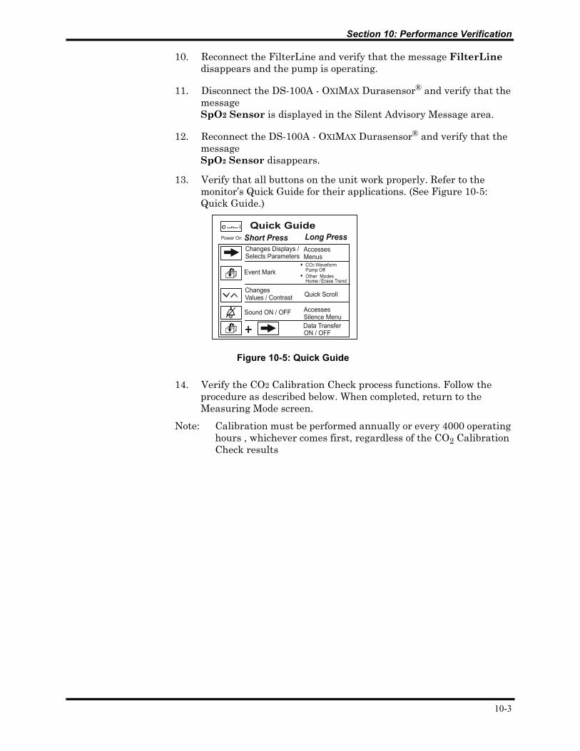
13. Verify that all buttons on the unit work properly. Refer to the monitor’s Quick Guide for their applications. (See Figure 10-5: Quick Guide.)
14. Verify the CO2 Calibration Check process functions. Follow the procedure as described below. When completed, return to the Measuring Mode screen.
Note: Calibration must be performed annually or every 4000 operating hours , whichever comes first, regardless of the CO2 Calibration Check results
Figure 10-5: Quick Guide
10-3
Section 10: Performance Verification
CO2 Calibration Check
Caution: Do not check CO2 values from the measuring mode if the BTPS setting is ON (factory default). This mode corrects the CO2 value for BTPS. The calibration check mode disables this correction automatically.
In order to ensure accuracy, a CO2 calibration check needs to be done once a year. Calibration gas and a FilterLine are needed for this procedure. Start the process from the Interface Test screen (refer to Table 4-1: "Accessing Service Mode and Changing Parameter Settings") as follows in “Table 10-1: CO2 Calibration Check”.
Note: Connect the FilterLine to the monitor before starting CO2 Calibration Check. Use the calibration kit (5% gas in air and connecting means) approved by Oridion Medical 1987 Ltd.
Note: If the CO2 Calibration Check is performed on a battery powered device, ensure that the battery is fully charged prior to calibration.
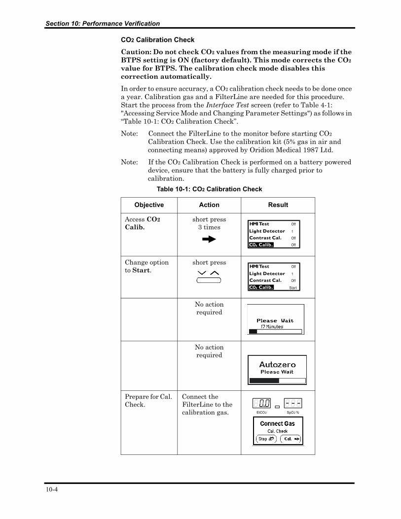
Table 10-1: CO2 Calibration Check
Objective Action Result
Access CO2 Calib.
short press 3 times
Change option to Start.
short press
No action required
No action required
Prepare for Cal. Check.
Connect the FilterLine to the calibration gas.
10-4
Section 10: Performance Verification
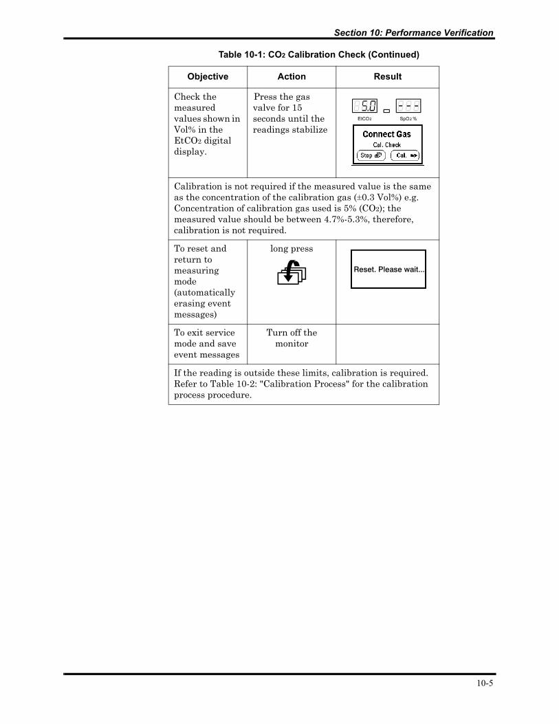
Check the measured values shown in Vol% in the EtCO2 digital display.
Press the gas valve for 15 seconds until the readings stabilize
Calibration is not required if the measured value is the same as the concentration of the calibration gas (±0.3 Vol%) e.g. Concentration of calibration gas used is 5% (CO2); the measured value should be between 4.7%-5.3%, therefore, calibration is not required.
To reset and return to measuring mode (automatically erasing event messages)
long press
To exit service mode and save event messages
Turn off the monitor
If the reading is outside these limits, calibration is required. Refer to Table 10-2: "Calibration Process" for the calibration process procedure.
Table 10-1: CO2 Calibration Check (Continued)
Objective Action Result
10-5
Section 10: Performance Verification
10-6
Calibration Process
If calibration is required, perform the Calibration Process (after performing CO2 Calibration Check) as shown in Table 10-2: "Calibration Process".
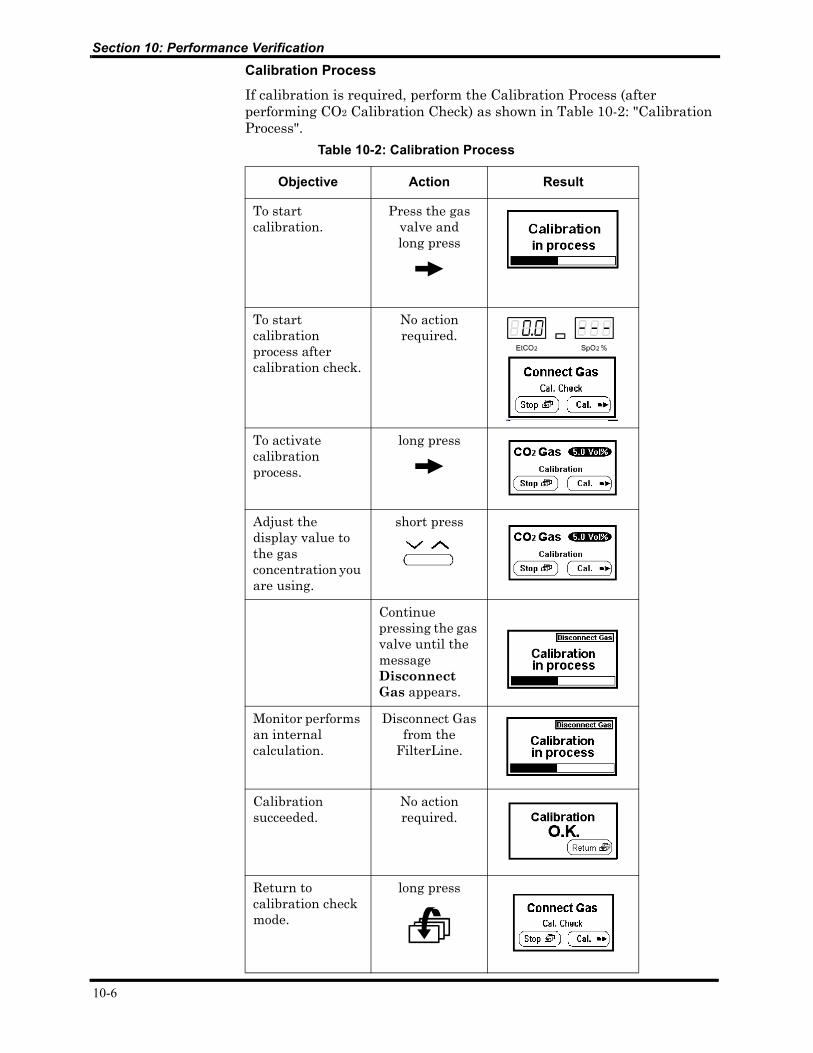
Table 10-2: Calibration Process
Objective Action Result
To start calibration.
Press the gas valve andlong press
To start calibration process after calibration check.
No action required.
To activate calibration process.
long press
Adjust the display value to the gas concentration you are using.
short press
Continue pressing the gas valve until the message Disconnect Gas appears.
Monitor performs an internal calculation.
Disconnect Gas from the
FilterLine.
Calibration succeeded.
No action required.
Return to calibration check mode.
long press
Section 10: Performance Verification
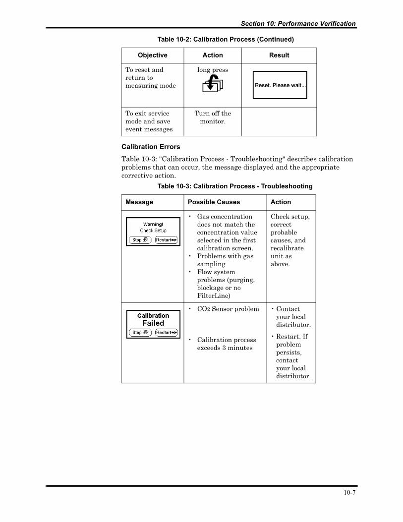
Calibration Errors
Table 10-3: "Calibration Process - Troubleshooting" describes calibration problems that can occur, the message displayed and the appropriate corrective action.
To reset and return to measuring mode
long press
To exit service mode and save event messages
Turn off the monitor.
Table 10-3: Calibration Process - Troubleshooting
Message Possible Causes Action
• Gas concentration does not match the concentration value selected in the first calibration screen.
• Problems with gas sampling
• Flow system problems (purging, blockage or no FilterLine)
Check setup, correct probable causes, and recalibrate unit as above.
• CO2 Sensor problem
• Calibration process exceeds 3 minutes
• Contact your local distributor.
• Restart. If problem persists, contact your local distributor.
Table 10-2: Calibration Process (Continued)
Objective Action Result
10-7

Section 10: Performance Verification
15. Advance to the Plethysmograph Display Screen as described in Table 10-4: "Plethysmograph Waveform" below.
16. Connect the DS-100A - OXIMAX Durasensor® to your finger. Verify the SpO2 value appears on the LED digital display and the Pulse rate appears on the LCD graphic display.
17. Disconnect the monitor from the AC power supply. Verify the unit continues to work from its battery pack and the battery icon appears on the lower right corner of the display.
18. Reconnect the monitor to main line power with the AC adapter. Verify that the unit functions, and the plug icon appears.
Note: If the battery pack has a low charge level, the battery icon will appear instead of the plug. The battery icon will fill indicating the battery charging process.
Table 10-4: Plethysmograph Waveform
To View Action ScreenCO2 waveform (Measuring Mode)
No action required.
Plethysmograph short press (x4)
10-8
Section 10: Performance Verification
To verify printing functions:
19. Adjust the printer to the following communication settings:Input SerialData Length 8 bitsParity Settings NoneBaud 9600 bps
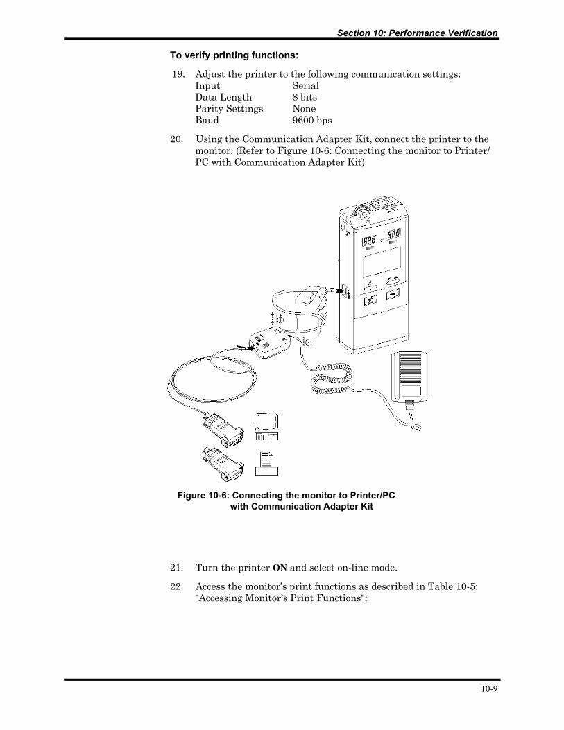
20. Using the Communication Adapter Kit, connect the printer to the monitor. (Refer to Figure 10-6: Connecting the monitor to Printer/PC with Communication Adapter Kit)
21. Turn the printer ON and select on-line mode.
22. Access the monitor’s print functions as described in Table 10-5: "Accessing Monitor’s Print Functions":
Figure 10-6: Connecting the monitor to Printer/PC with Communication Adapter Kit
10-9
Section 10: Performance Verification
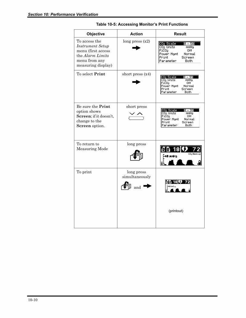
Table 10-5: Accessing Monitor’s Print Functions
Objective Action Result
To access the Instrument Setup menu (first access the Alarm Limits menu from any measuring display)
long press (x2)
To select Print short press (x4)
Be sure the Print option shows Screen; if it doesn’t, change to the Screen option.
short press
To return to Measuring Mode
long press
To print long press simultaneously
and
(printout)
10-10
SECTION 11: PACKING FOR SHIPMENT11.1 General Instructions11.2 Packing Handheld Capnograph in Original Carton11.3 Packing in a Different Carton
11.1 GENERAL INSTRUCTIONS
To ship a monitor or one of its components for any reason, follow the instructions in this section. Failure to follow the instructions in this section may result in loss or damage not covered by any applicable manufacturer warranty.
Pack the monitor or component(s) carefully. If available, use the original carton and packing materials and follow the instructions in “Packing monitor in Original Carton.” If the original shipping carton and material are not available, use other suitable shipping materials and container and follow the instructions in “Packing in a Different Carton.”
Prior to shipping the monitor or a component, contact your local representative for a Returned Material Authorization (RMA) number. Mark the shipping carton and any shipping forms with the RMA and the monitor’s serial number.
Caution: Observe ESD (electrostatic discharge) precautions when packing any monitor components.
11.2 PACKING MONITOR IN ORIGINAL CARTON
If the original carton and packing material are available, repack the monitor as follows. (Refer to Figure 11-1: Packing the Monitor in Original Packing.)
1. Place the unit in a plastic bag. Place it into the corresponding space, in the original foam padding, with the front panel facing up.
2. Place the foam padding cover over the top of the unit.
3. Seal the carton with packing tape.
4. Label the carton with the correct shipping address, return address and RMA number.
11.3 PACKING IN A DIFFERENT CARTON
If the original carton and packing material are not available or if shipping any monitor component not in its original carton:
1. Place the monitor in a plastic bag or component in a plastic anti-static bag.
2. Locate a corrugated cardboard shipping carton (approximately the size of the monitor or component) with at least 200 pounds per square inch (psi) bursting strength.
3. Fill the bottom of the carton with at least 2 inches of packing material.
11-1

Section 11: Packing For Shipment
4. Place the bagged monitor or component on the layer of packing material and fill the box completely with packing material such that there is at least 2 inches of packing material around all sides of the item.
5. Seal the carton with packing tape.
6. Label carton with shipping address, return address and RMA number.
Figure 11-1: Packing the Monitor in Original Packing
11-2
SECTION 12: SPECIFICATIONS12.1 Physical12.2 Environmental12.3 Safety Standards12.4 Performance12.5 Power Specifications12.6 Components and User Interface
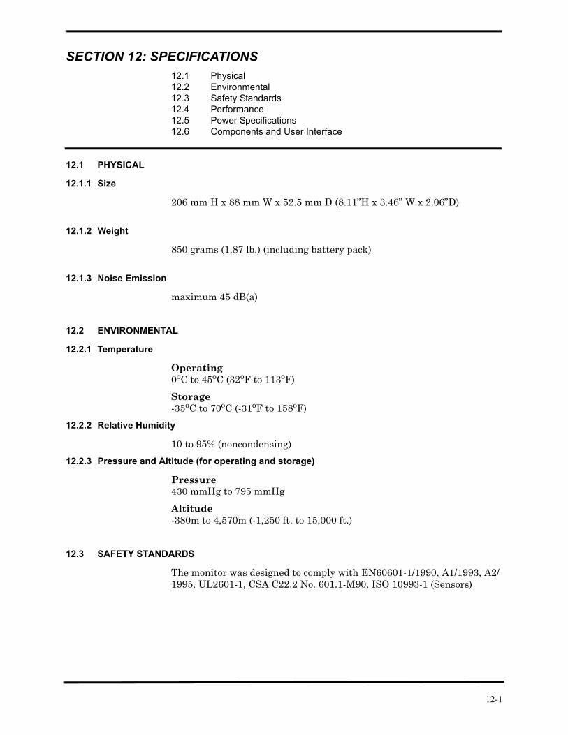
12.1 PHYSICAL
12.1.1 Size
206 mm H x 88 mm W x 52.5 mm D (8.11”H x 3.46” W x 2.06”D)
12.1.2 Weight
850 grams (1.87 lb.) (including battery pack)
12.1.3 Noise Emission
maximum 45 dB(a)
12.2 ENVIRONMENTAL
12.2.1 Temperature
Operating0oC to 45oC (32oF to 113oF)
Storage-35oC to 70oC (-31oF to 158oF)
12.2.2 Relative Humidity
10 to 95% (noncondensing)
12.2.3 Pressure and Altitude (for operating and storage)
Pressure430 mmHg to 795 mmHg
Altitude-380m to 4,570m (-1,250 ft. to 15,000 ft.)
12.3 SAFETY STANDARDS
The monitor was designed to comply with EN60601-1/1990, A1/1993, A2/1995, UL2601-1, CSA C22.2 No. 601.1-M90, ISO 10993-1 (Sensors)
12-1
Section 12: Specifications
12.4 PERFORMANCE
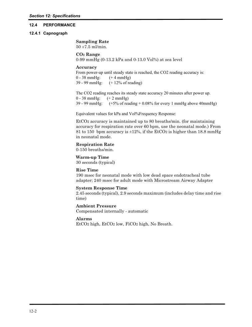
12.4.1 Capnograph
Sampling Rate50 ±7.5 ml/min.
CO2 Range0-99 mmHg (0-13.2 kPa and 0-13.0 Vol%) at sea level
AccuracyFrom power-up until steady state is reached, the CO2 reading accuracy is:0 - 38 mmHg: (+ 4 mmHg)39 - 99 mmHg: (+ 12% of reading)
The CO2 reading reaches its steady state accuracy 20 minutes after power up.0 - 38 mmHg: (+ 2 mmHg)39 - 99 mmHg: (+5% of reading + 0.08% for every 1 mmHg above 40mmHg)
Equivalent values for kPa and Vol%Frequency Response:
EtCO2 accuracy is maintained up to 80 breaths/min. (for maintaining accuracy for respiration rate over 60 bpm, use the neonatal mode.) From 81 to 150 bpm accuracy is ±12%, if the EtCO2 is higher than 18.8 mmHg in neonatal mode.
Respiration Rate0-150 breaths/min.
Warm-up Time30 seconds (typical)
Rise Time190 msec for neonatal mode with low dead space endotracheal tube adapter; 240 msec for adult mode with Microstream Airway Adapter
System Response Time2.45 seconds (typical), 2.9 seconds maximum (includes delay time and rise time)
Ambient PressureCompensated internally - automatic
AlarmsEtCO2 high, EtCO2 low, FiCO2 high, No Breath.
12-2
Section 12: Specifications
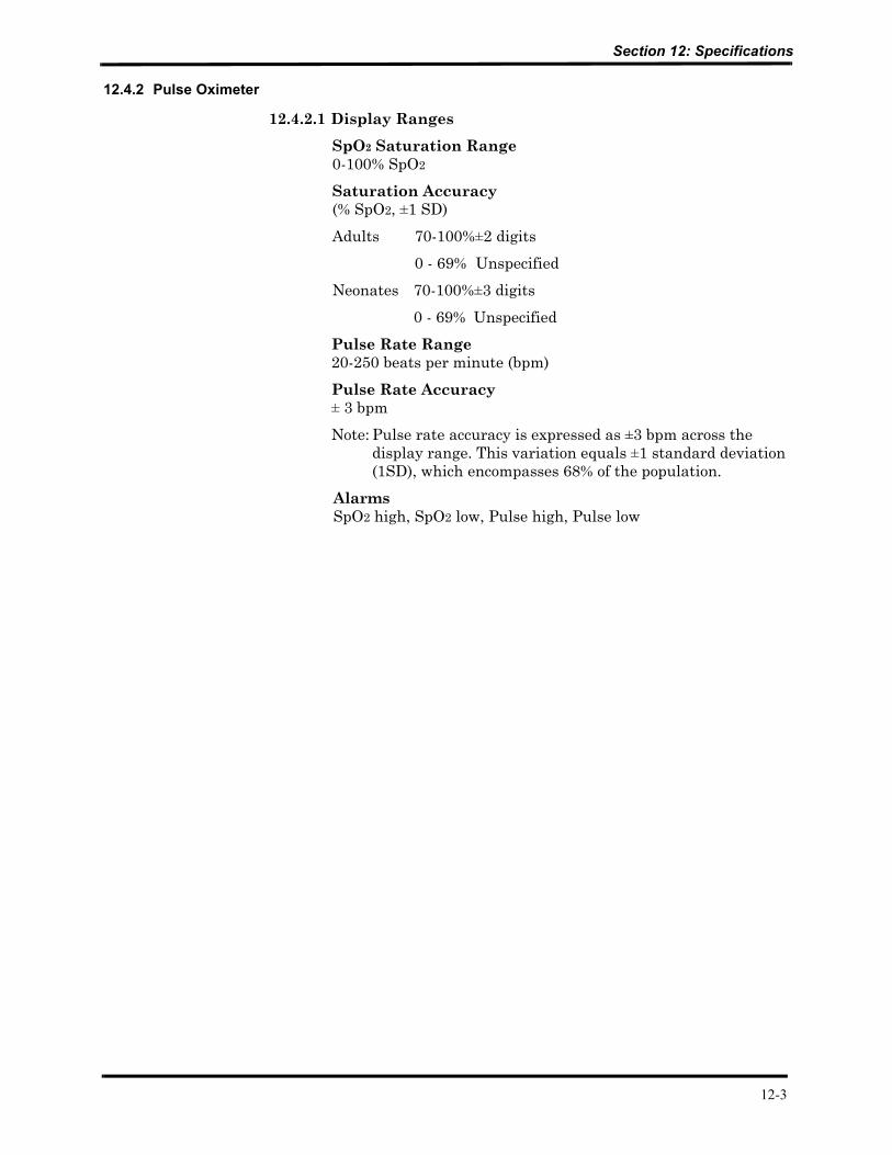
12.4.2 Pulse Oximeter
12.4.2.1 Display Ranges
SpO2 Saturation Range0-100% SpO2
Saturation Accuracy(% SpO2, ±1 SD)
Adults 70-100%±2 digits
0 - 69% Unspecified
Neonates 70-100%±3 digits
0 - 69% Unspecified
Pulse Rate Range20-250 beats per minute (bpm)
Pulse Rate Accuracy± 3 bpm
Note: Pulse rate accuracy is expressed as ±3 bpm across the display range. This variation equals ±1 standard deviation (1SD), which encompasses 68% of the population.
AlarmsSpO2 high, SpO2 low, Pulse high, Pulse low
12-3
Section 12: Specifications
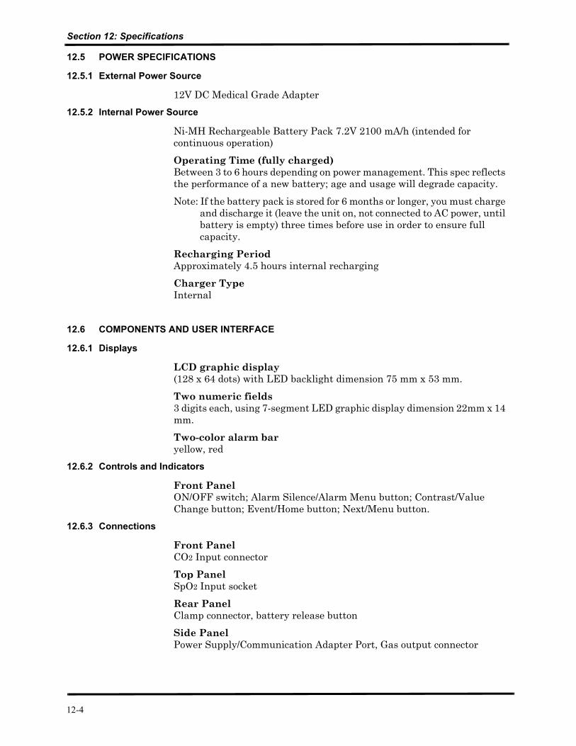
12.5 POWER SPECIFICATIONS
12.5.1 External Power Source
12V DC Medical Grade Adapter
12.5.2 Internal Power Source
Ni-MH Rechargeable Battery Pack 7.2V 2100 mA/h (intended for continuous operation)
Operating Time (fully charged)Between 3 to 6 hours depending on power management. This spec reflects the performance of a new battery; age and usage will degrade capacity.
Note: If the battery pack is stored for 6 months or longer, you must charge and discharge it (leave the unit on, not connected to AC power, until battery is empty) three times before use in order to ensure full capacity.
Recharging PeriodApproximately 4.5 hours internal recharging
Charger TypeInternal
12.6 COMPONENTS AND USER INTERFACE
12.6.1 Displays
LCD graphic display (128 x 64 dots) with LED backlight dimension 75 mm x 53 mm.
Two numeric fields 3 digits each, using 7-segment LED graphic display dimension 22mm x 14 mm.
Two-color alarm baryellow, red
12.6.2 Controls and Indicators
Front PanelON/OFF switch; Alarm Silence/Alarm Menu button; Contrast/Value Change button; Event/Home button; Next/Menu button.
12.6.3 Connections
Front PanelCO2 Input connector
Top PanelSpO2 Input socket
Rear PanelClamp connector, battery release button
Side PanelPower Supply/Communication Adapter Port, Gas output connector
12-4

13-1
SECTION 13: SPARE PARTS13.1 Spare Parts List
13.1 SPARE PARTS LIST
Spare parts are shown below in Table 13-1. For spare part numbers contact your local distributor.
Table 13-1: Spare Parts List
Item Description
1 CO2 board - includes electronic board, sensor, pump and scrubber, solenoid, LCD, 7-segment display, flow system, CO2 input connector, software EPROM and screws.
2 Software Assembly - includes EPROM chip and last updated software version.
3 SpO2 Board
4 SpO2 Kit - includes inter-board connection cable,SpO2 input cable, SpO2 insulation plate and internal connector lock
5 Housing Kit - includes front cover, rear cover, ON/OFF button, keypads, gas outlet, screws, external SpO2 connector latch, SpO2 insulation plate and internal SpO2 connector lock
6 7-Segment Digital Display (x2)
7 LCD Assembly - Graphic Display Screen and PC driver
8 Calibration Gas (5% CO2 in air) and FilterLine
9 Leak Test Jig - vacuum test accessories
10 Communication Adapter Kit
11 Battery Pack
12 Pump Assembly
13 Flow System
GLOSSARY OF TERMS
BIT: Built in Tests.
BTPS: Body Temperature, Pressure and Saturation Compensation.
Where Body Temperature is assumed 37°C with vapor pressure 47mmHg
The Calculations are made according to:
PCO2 = FCO2 x (Pb - 47)
Where:
FCO2 is the Fractional concentration of CO2 in Dry gas, FCO2 = % CO2/100
Pb = the ambient pressure
PCO2 = the partial pressure of CO2 at BTPS
EPROM: Erasable Programmable Read Only Memory.
ESD: Electrostatic Discharge.
EtCO2: End Tidal Carbon Dioxide: amount of CO2 present at the end of the exhalation.
FiCO2: Fractional Inspired Carbon Dioxide: amount of CO2 present during inhalation.
FRS: FilterLine Recognition Safeguard.
LCD: Liquid Crystal Display.
HMI: Human Machine Interface.
Respiration Rate: Number of respiratory cycles (inhalation and exhalation) per minute.
7-segments LED: Graphic display of seven segments of light emitter diodes.
Solenoid: 2-way electro-pneumatic valve controlling the directional flow either from the patient or from the CO2 Scrubber (during Autozero).
Scrubber: Lithium compound CO2 absorber.