Embed Size (px)
Citation preview

MCP3004/30082.7V 4-Channel/8-Channel 10-Bit A/D Converters
with SPI™ Serial Interface
Features
• 10-bit resolution
• ± 1 LSB max DNL• ± 1 LSB max INL • 4 (MCP3004) or 8 (MCP3008) input channels
• Analog inputs programmable as single-ended or pseudo-differential pairs
• On-chip sample and hold• SPI serial interface (modes 0,0 and 1,1)• Single supply operation: 2.7V - 5.5V
• 200 ksps max. sampling rate at VDD = 5V• 75 ksps max. sampling rate at VDD = 2.7V• Low power CMOS technology
• 5 nA typical standby current, 2 µA max.• 500 µA max. active current at 5V• Industrial temp range: -40°C to +85°C
• Available in PDIP, SOIC and TSSOP packages
Applications
• Sensor Interface• Process Control• Data Acquisition
• Battery Operated Systems
Package Types
Description
The Microchip Technology Inc. MCP3004/3008devices are successive approximation 10-bit Analog-to-Digital (A/D) converters with on-board sample andhold circuitry. The MCP3004 is programmable to pro-vide two pseudo-differential input pairs or four single-ended inputs. The MCP3008 is programmable to pro-vide four pseudo-differential input pairs or eight single-ended inputs. Differential Nonlinearity (DNL) and Inte-gral Nonlinearity (INL) are specified at ±1 LSB. Com-munication with the devices is accomplished using asimple serial interface compatible with the SPI protocol.The devices are capable of conversion rates of up to200 ksps. The MCP3004/3008 devices operate over abroad voltage range (2.7V - 5.5V). Low current designpermits operation with typical standby currents of only5 nA and typical active currents of 320 µA. TheMCP3004 is offered in 14-pin PDIP, 150 mil SOIC andTSSOP packages, while the MCP3008 is offered in 16-pin PDIP and SOIC packages.
Functional Block Diagram
VDD
CLKDOUT
MC
P3004
1234
1413121110
98
567
VREF
DIN
CH0CH1CH2CH3
CS/SHDNDGND
AGND
NC
VDD
CLKDOUT
MC
P3008
1234
161514131211109
5678
VREF
DINCS/SHDNDGND
CH0CH1CH2CH3CH4CH5CH6CH7
NC
AGND
PDIP, SOIC, TSSOP
PDIP, SOIC
Comparator
Sampleand Hold
10-Bit SAR
DAC
Control Logic
CS/SHDN
VREF
VSSVDD
CLK DOUT
ShiftRegister
CH0
ChannelMax
InputCH1
CH7*
* Note: Channels 4-7 available on MCP3008 Only
DIN
© 2007 Microchip Technology Inc. DS21295C-page 1

MCP3004/3008
1.0 ELECTRICAL CHARACTERISTICS
Absolute Maximum Ratings*
VDD........................................................................7.0V
All inputs and outputs w.r.t. VSS .....-0.6V to VDD +0.6V
Storage temperature ..........................-65°C to +150°C
Ambient temp. with power applied .....-65°C to +125°C
Soldering temperature of leads (10 seconds) .. +300°C
ESD protection on all pins ..................................> 4 kV
*Notice: Stresses above those listed under "MaximumRatings" may cause permanent damage to the device. This isa stress rating only and functional operation of the device atthose or any other conditions above those indicated in theoperation listings of this specification is not implied. Exposureto maximum rating conditions for extended periods may affectdevice reliability.
PIN FUNCTION TABLE
Name Function
VDD +2.7V to 5.5V Power Supply
DGND Digital Ground
AGND Analog Ground
CH0-CH7 Analog Inputs
CLK Serial Clock
DIN Serial Data In
DOUT Serial Data Out
CS/SHDN Chip Select/Shutdown Input
VREF Reference Voltage Input
ELECTRICAL SPECIFICATIONS
Electrical Characteristics: Unless otherwise noted, all parameters apply at VDD = 5V, VREF = 5V, TAMB = -40°C to +85°C, fSAMPLE = 200 ksps and fCLK = 18*fSAMPLE. Unless otherwise noted, typical values apply for VDD = 5V, TAMB = 25°C.
Parameter Sym Min Typ Max Units Conditions
Conversion Rate
Conversion Time tCONV — — 10 clock cycles
Analog Input Sample Time tSAMPLE 1.5 clock cycles
Throughput Rate fSAMPLE — — 20075
kspsksps
VDD = VREF = 5VVDD = VREF = 2.7V
DC Accuracy
Resolution 10 bits
Integral Nonlinearity INL — ±0.5 ±1 LSB
Differential Nonlinearity DNL — ±0.25 ±1 LSB No missing codes overtemperature
Offset Error — — ±1.5 LSB
Gain Error — — ±1.0 LSB
Dynamic Performance
Total Harmonic Distortion — -76 dB VIN = 0.1V to 4.9V@1 kHz
Signal to Noise and Distortion (SINAD)
— 61 dB VIN = 0.1V to 4.9V@1 kHz
Spurious Free Dynamic Range — 78 dB VIN = 0.1V to 4.9V@1 kHz
Reference Input
Voltage Range 0.25 — VDD V Note 2
Current Drain — 1000.001
1503
µAµA CS = VDD = 5V
Note 1: This parameter is established by characterization and not 100% tested.2: See graphs that relate linearity performance to VREF levels.3: Because the sample cap will eventually lose charge, effective clock rates below 10 kHz can affect linearity
performance, especially at elevated temperatures. See Section 6.2, “Maintaining Minimum Clock Speed”, for more information.
DS21295C-page 2 © 2007 Microchip Technology Inc.

MCP3004/3008
Analog Inputs
Input Voltage Range for CH0 or CH1 in Single-Ended Mode
VSS — VREF V
Input Voltage Range for IN+ in pseudo-differential mode
IN- — VREF+IN-
Input Voltage Range for IN- in pseudo-differential mode
VSS-100 — VSS+100 mV
Leakage Current — 0.001 ±1 µA
Switch Resistance — 1000 — Ω See Figure 4-1
Sample Capacitor — 20 — pF See Figure 4-1
Digital Input/Output
Data Coding Format Straight Binary
High Level Input Voltage VIH 0.7 VDD — — V
Low Level Input Voltage VIL — 0.3 VDD V
High Level Output Voltage VOH 4.1 — — V IOH = -1 mA, VDD = 4.5V
Low Level Output Voltage VOL — — 0.4 V IOL = 1 mA, VDD = 4.5V
Input Leakage Current ILI -10 — 10 µA VIN = VSS or VDD
Output Leakage Current ILO -10 — 10 µA VOUT = VSS or VDD
Pin Capacitance(All Inputs/Outputs)
CIN,COUT
— — 10 pF VDD = 5.0V (Note 1)TAMB = 25°C, f = 1 MHz
Timing Parameters
Clock Frequency fCLK — — 3.61.35
MHzMHz
VDD = 5V (Note 3)VDD = 2.7V (Note 3)
Clock High Time tHI 125 — — ns
Clock Low Time tLO 125 — — ns
CS Fall To First Rising CLK Edge tSUCS 100 — — ns
CS Fall To Falling CLK Edge tCSD — — 0 ns
Data Input Setup Time tSU — — 50 ns
Data Input Hold Time tHD — — 50 ns
CLK Fall To Output Data Valid tDO — — 125200
nsns
VDD = 5V, See Figure 1-2VDD = 2.7V, See Figure 1-2
CLK Fall To Output Enable tEN — — 125200
nsns
VDD = 5V, See Figure 1-2VDD = 2.7V, See Figure 1-2
CS Rise To Output Disable tDIS — — 100 ns See Test Circuits, Figure 1-2
CS Disable Time tCSH 270 — — ns
DOUT Rise Time tR — — 100 ns See Test Circuits, Figure 1-2 (Note 1)
DOUT Fall Time tF — — 100 ns See Test Circuits, Figure 1-2 (Note 1)
ELECTRICAL SPECIFICATIONS (CONTINUED)
Electrical Characteristics: Unless otherwise noted, all parameters apply at VDD = 5V, VREF = 5V, TAMB = -40°C to +85°C, fSAMPLE = 200 ksps and fCLK = 18*fSAMPLE. Unless otherwise noted, typical values apply for VDD = 5V, TAMB = 25°C.
Parameter Sym Min Typ Max Units Conditions
Note 1: This parameter is established by characterization and not 100% tested.2: See graphs that relate linearity performance to VREF levels.3: Because the sample cap will eventually lose charge, effective clock rates below 10 kHz can affect linearity
performance, especially at elevated temperatures. See Section 6.2, “Maintaining Minimum Clock Speed”, for more information.
© 2007 Microchip Technology Inc. DS21295C-page 3

MCP3004/3008
FIGURE 1-1: Serial Interface Timing.
Power Requirements
Operating Voltage VDD 2.7 — 5.5 V
Operating Current IDD — 425225
550 µA VDD = VREF = 5V,DOUT unloadedVDD = VREF = 2.7V,DOUT unloaded
Standby Current IDDS — 0.005 2 µA CS = VDD = 5.0V
Temperature Ranges
Specified Temperature Range TA -40 — +85 °C
Operating Temperature Range TA -40 — +85 °C
Storage Temperature Range TA -65 — +150 °C
Thermal Package Resistance
Thermal Resistance, 14L-PDIP θJA — 70 — °C/W
Thermal Resistance, 14L-SOIC θJA — 108 — °C/W
Thermal Resistance, 14L-TSSOP θJA — 100 — °C/W
Thermal Resistance, 16L-PDIP θJA — 70 — °C/W
Thermal Resistance, 16L-SOIC θJA — 90 — °C/W
ELECTRICAL SPECIFICATIONS (CONTINUED)
Electrical Characteristics: Unless otherwise noted, all parameters apply at VDD = 5V, VREF = 5V, TAMB = -40°C to +85°C, fSAMPLE = 200 ksps and fCLK = 18*fSAMPLE. Unless otherwise noted, typical values apply for VDD = 5V, TAMB = 25°C.
Parameter Sym Min Typ Max Units Conditions
Note 1: This parameter is established by characterization and not 100% tested.2: See graphs that relate linearity performance to VREF levels.3: Because the sample cap will eventually lose charge, effective clock rates below 10 kHz can affect linearity
performance, especially at elevated temperatures. See Section 6.2, “Maintaining Minimum Clock Speed”, for more information.
CS
CLK
DIN MSB IN
TSU THD
TSUCS
TCSH
THI TLO
DOUT
TEN
TDO TR TF
LSBMSB OUT
TDIS
NULL BIT
DS21295C-page 4 © 2007 Microchip Technology Inc.

MCP3004/3008
FIGURE 1-2: Load Circuit for tR, tF, tDO.
FIGURE 1-3: Load circuit for tDIS and tEN.
Test Point
1.4V
DOUT
3 kΩ
CL = 100 pF
DOUT
tR
Voltage Waveforms for tR, tF
CLK
DOUT
tDO
Voltage Waveforms for tDO
tF
VOHVOL
90%
10%
* Waveform 1 is for an output with internal conditions such that the output is high, unless disabled by the output control.
† Waveform 2 is for an output with internal conditions such that the output is low, unless disabled by the output control.
Test Point
DOUT
3 kΩ
100 pF
tDIS Waveform 2
tDIS Waveform 1
CS
CLK
DOUT
tEN
1 2
B9
Voltage Waveforms for tEN
tEN Waveform
VDD
VDD/2
VSS
3 4
Voltage Waveforms for tDIS
DOUT
DOUT
CSVIH
TDIS
Waveform 1*
Waveform 2†
© 2007 Microchip Technology Inc. DS21295C-page 5

MCP3004/3008
2.0 TYPICAL PERFORMANCE CHARACTERISTICS
Note: Unless otherwise indicated, VDD = VREF = 5V, fCLK = 18* fSAMPLE, TA = 25°C.
FIGURE 2-1: Integral Nonlinearity (INL) vs. Sample Rate.
FIGURE 2-2: Integral Nonlinearity (INL) vs. VREF.
FIGURE 2-3: Integral Nonlinearity (INL) vs. Code (Representative Part).
FIGURE 2-4: Integral Nonlinearity (INL) vs. Sample Rate (VDD = 2.7V).
FIGURE 2-5: Integral Nonlinearity (INL) vs. VREF (VDD = 2.7V).
FIGURE 2-6: Integral Nonlinearity (INL) vs. Code (Representative Part, VDD = 2.7V).
Note: The graphs and tables provided following this note are a statistical summary based on a limited number ofsamples and are provided for informational purposes only. The performance characteristics listed hereinare not tested or guaranteed. In some graphs or tables, the data presented may be outside the specifiedoperating range (e.g., outside specified power supply range) and therefore outside the warranted range.
-1.0
-0.8
-0.6
-0.4
-0.2
0.0
0.2
0.4
0.6
0.8
1.0
0 25 50 75 100 125 150 175 200 225 250
Sample Rate (ksps)
INL
(L
SB
) Positive INL
Negative INL
-1.0-0.8
-0.6-0.4
-0.20.0
0.20.4
0.6
0.81.0
0 1 2 3 4 5 6
VREF (V)
INL
(LS
B) Positive INL
Negative INL
-0.5
-0.4
-0.3
-0.2
-0.1
0.0
0.1
0.2
0.3
0.4
0.5
0 128 256 384 512 640 768 896 1024
Digital Code
INL
(L
SB
)
VDD = VREF = 5 VfSAMPLE = 200 ksps
-1.0
-0.8
-0.6
-0.4
-0.2
0.0
0.2
0.4
0.6
0.8
1.0
0 25 50 75 100
Sample Rate (ksps)
INL
(L
SB
) Positive INL
Negative INL
VDD = VREF = 2.7 V
-1.0
-0.8
-0.6
-0.4
-0.2
0.0
0.2
0.4
0.6
0.8
1.0
0.0 0.5 1.0 1.5 2.0 2.5 3.0
VREF (V)
INL
(LS
B) Positive INL
Negative INL
VDD = VREF = 2.7 VfSAMPLE = 75 ksps
-0.5
-0.4
-0.3
-0.2
-0.1
0.0
0.1
0.2
0.3
0.4
0.5
0 128 256 384 512 640 768 896 1024
Digital Code
INL
(L
SB
)
VDD = VREF = 2.7 VfSAMPLE = 75 ksps
DS21295C-page 6 © 2007 Microchip Technology Inc.

MCP3004/3008
Note: Unless otherwise indicated, VDD = VREF = 5V, fCLK = 18* fSAMPLE, TA = 25°C.
FIGURE 2-7: Integral Nonlinearity (INL) vs. Temperature.
FIGURE 2-8: Differential Nonlinearity (DNL) vs. Sample Rate.
FIGURE 2-9: Differential Nonlinearity (DNL) vs. VREF.
FIGURE 2-10: Integral Nonlinearity (INL) vs. Temperature (VDD = 2.7V).
FIGURE 2-11: Differential Nonlinearity (DNL) vs. Sample Rate (VDD = 2.7V).
FIGURE 2-12: Differential Nonlinearity (DNL) vs. VREF (VDD = 2.7V).
-0.6
-0.4
-0.2
0.0
0.2
0.4
0.6
-50 -25 0 25 50 75 100
Temperature (°C)
INL
(L
SB
)
Positive INL
Negative INL
-0.6
-0.4
-0.2
0.0
0.2
0.4
0.6
0 25 50 75 100 125 150 175 200 225 250
Sample Rate (ksps)
DN
L (
LS
B)
Positive DNL
Negative DNL
-1.0
-0.8
-0.6
-0.4
-0.2
0.0
0.2
0.4
0.6
0.8
1.0
0 1 2 3 4 5
VREF (V)
DN
L (
LS
B)
Negative DNL
Positive DNL
-0.6
-0.4
-0.2
0.0
0.2
0.4
0.6
-50 -25 0 25 50 75 100
Temperature (°C)
INL
(L
SB
)
Positive INL
VDD = VREF = 2.7 VfSAMPLE = 75 ksps
Negative INL
-0.6
-0.4
-0.2
0.0
0.2
0.4
0.6
0 25 50 75 100
Sample Rate (ksps)
DN
L (
LS
B)
Positive DNL
Negative DNL
VDD = VREF = 2.7 V
-1.0
-0.8
-0.6
-0.4
-0.2
0.0
0.2
0.4
0.6
0.8
0.0 0.5 1.0 1.5 2.0 2.5 3.0VREF(V)
DN
L (
LS
B)
Positive DNL
Negative DNL
VDD = VREF = 2.7 VfSAMPLE = 75 ksps
© 2007 Microchip Technology Inc. DS21295C-page 7

MCP3004/3008
Note: Unless otherwise indicated, VDD = VREF = 5V, fCLK = 18* fSAMPLE, TA = 25°C.
FIGURE 2-13: Differential Nonlinearity (DNL) vs. Code (Representative Part).
FIGURE 2-14: Differential Nonlinearity (DNL) vs. Temperature.
FIGURE 2-15: Gain Error vs. VREF.
FIGURE 2-16: Differential Nonlinearity (DNL) vs. Code (Representative Part, VDD = 2.7V).
FIGURE 2-17: Differential Nonlinearity (DNL) vs. Temperature (VDD = 2.7V).
FIGURE 2-18: Offset Error vs. VREF.
-1.0
-0.8
-0.6
-0.4
-0.2
0.0
0.2
0.4
0.6
0.8
1.0
0 128 256 384 512 640 768 896 1024
Digital Code
DN
L (
LS
B)
VDD = VREF = 5 VfSAMPLE = 200 ksps
-0.6
-0.4
-0.2
0.0
0.2
0.4
0.6
-50 -25 0 25 50 75 100
Temperature (°C)
DN
L (
LS
B)
Positive DNL
Negative DNL
-2.0
-1.5
-1.0
-0.5
0.0
0.5
1.0
1.5
2.0
0 1 2 3 4 5
VREF(V)
Gai
n E
rro
r (L
SB
) VDD = 2.7 VfSAMPLE = 75 ksps
VDD = 5 VfSAMPLE = 200 ksps
-1.0
-0.8
-0.6
-0.4
-0.2
0.0
0.2
0.4
0.6
0.8
1.0
0 128 256 384 512 640 768 896 1024
Digital Code
DN
L (
LS
B)
VDD = VREF = 2.7 VfSAMPLE = 75 ksps
-0.6
-0.4
-0.2
0.0
0.2
0.4
0.6
-50 -25 0 25 50 75 100
Temperature (°C)
DN
L (
LS
B) Positive DNL
VDD = VREF = 2.7 VfSAMPLE = 75 ksps
Negative DNL
0
1
2
3
4
5
6
7
8
0 1 2 3 4 5
VREF (V)
Off
set
Err
or
(LS
B)
VDD = 5 VfSAMPLE = 200 ksps
VDD = 2.7 VfSAMPLE = 75 ksps
DS21295C-page 8 © 2007 Microchip Technology Inc.

MCP3004/3008
Note: Unless otherwise indicated, VDD = VREF = 5V, fCLK = 18* fSAMPLE, TA = 25°C.
FIGURE 2-19: Gain Error vs. Temperature.
FIGURE 2-20: Signal to Noise (SNR) vs. Input Frequency.
FIGURE 2-21: Total Harmonic Distortion (THD) vs. Input Frequency.
FIGURE 2-22: Offset Error vs. Temperature.
FIGURE 2-23: Signal to Noise and Distortion (SINAD) vs. Input Frequency.
FIGURE 2-24: Signal to Noise and Distortion (SINAD) vs. Input Signal Level.
-0.6
-0.5
-0.4
-0.3
-0.2
-0.1
0.0
-50 -25 0 25 50 75 100
Temperature (°C)
Gai
n E
rro
r (L
SB
)
VDD = VREF = 5 VfSAMPLE = 200 ksps
VDD = VREF = 2.7 VfSAMPLE = 75 ksps
0
10
20
30
40
50
60
70
80
1 10 100
Input Frequency (kHz)
SN
R (
dB
)
VDD = VREF = 2.7 VfSAMPLE = 75 ksps
VDD = VREF = 5 VfSAMPLE = 200 ksps
-100
-90
-80
-70
-60
-50
-40
-30
-20
-10
0
1 10 100
Input Frequency (kHz)
TH
D (
dB
)
VDD = VREF = 5 VfSAMPLE = 200 ksps
VDD = VREF = 2.7 VfSAMPLE = 75 ksps
0.0
0.2
0.4
0.6
0.8
1.0
1.2
-50 -25 0 25 50 75 100
Temperature (°C)
Off
set
Err
or
(LS
B)
VDD = VREF = 5 VfSAMPLE = 200 ksps
VDD = VREF = 2.7 VfSAMPLE = 75 ksps
0
10
20
30
40
50
60
70
80
1 10 100Input Frequency (kHz)
SIN
AD
(d
B)
VDD = VREF = 2.7 VfSAMPLE = 75 ksps
VDD = VREF = 5 VfSAMPLE = 200 ksps
0
10
20
30
40
50
60
70
-40 -35 -30 -25 -20 -15 -10 -5 0
Input Signal Level (dB)
SIN
AD
(d
B)
VDD = VREF = 2.7 VfSAMPLE = 75 ksps
VDD = VREF = 5 VfSAMPLE = 200 ksps
© 2007 Microchip Technology Inc. DS21295C-page 9
MCP3004/3008
Note: Unless otherwise indicated, VDD = VREF = 5V, fCLK = 18* fSAMPLE, TA = 25°C.
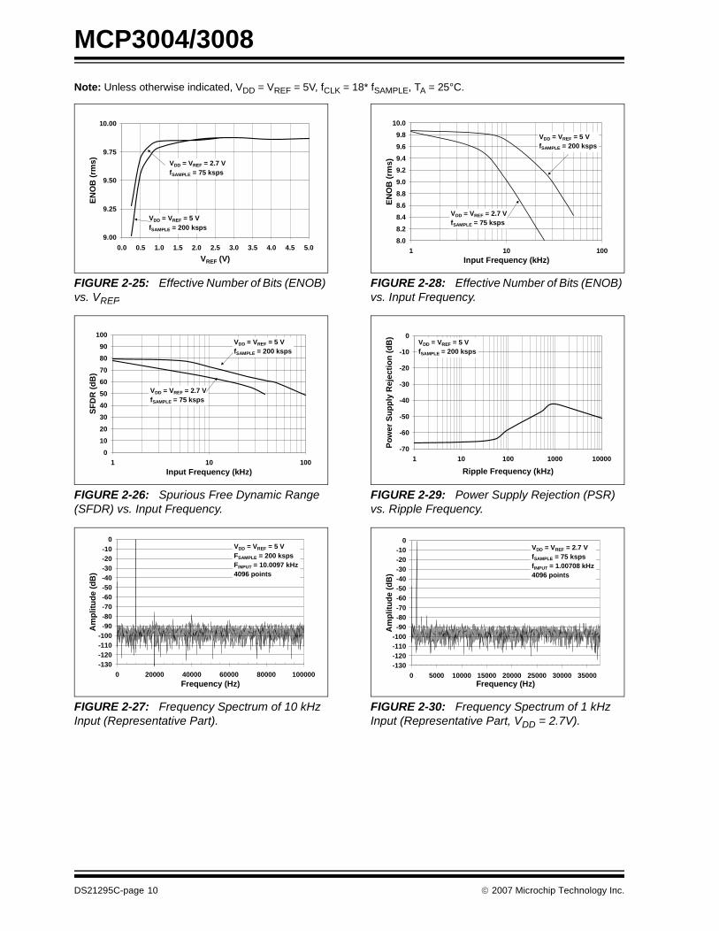
FIGURE 2-25: Effective Number of Bits (ENOB) vs. VREF.
FIGURE 2-26: Spurious Free Dynamic Range (SFDR) vs. Input Frequency.
FIGURE 2-27: Frequency Spectrum of 10 kHz Input (Representative Part).
FIGURE 2-28: Effective Number of Bits (ENOB) vs. Input Frequency.
FIGURE 2-29: Power Supply Rejection (PSR) vs. Ripple Frequency.
FIGURE 2-30: Frequency Spectrum of 1 kHz Input (Representative Part, VDD = 2.7V).
9.00
9.25
9.50
9.75
10.00
0.0 0.5 1.0 1.5 2.0 2.5 3.0 3.5 4.0 4.5 5.0
VREF (V)
EN
OB
(rm
s) VDD = VREF = 2.7 VfSAMPLE = 75 ksps
VDD = VREF = 5 VfSAMPLE = 200 ksps
0
10
20
30
40
50
60
70
80
90
100
1 10 100Input Frequency (kHz)
SF
DR
(d
B)
VDD = VREF = 5 VfSAMPLE = 200 ksps
VDD = VREF = 2.7 VfSAMPLE = 75 ksps
-130-120-110-100
-90-80-70-60-50-40-30-20-10
0
0 20000 40000 60000 80000 100000Frequency (Hz)
Am
plit
ud
e (d
B)
VDD = VREF = 5 VFSAMPLE = 200 kspsFINPUT = 10.0097 kHz4096 points
8.0
8.2
8.4
8.6
8.8
9.0
9.2
9.4
9.6
9.8
10.0
1 10 100Input Frequency (kHz)
EN
OB
(rm
s)
VDD = VREF = 2.7 VfSAMPLE = 75 ksps
VDD = VREF = 5 VfSAMPLE = 200 ksps
-70
-60
-50
-40
-30
-20
-10
0
1 10 100 1000 10000
Ripple Frequency (kHz)
Po
wer
Su
pp
ly R
ejec
tio
n (
dB
)
VDD = VREF = 5 VfSAMPLE = 200 ksps
-130-120-110-100
-90-80-70-60-50-40-30-20-10
0
0 5000 10000 15000 20000 25000 30000 35000Frequency (Hz)
Am
plit
ud
e (d
B)
VDD = VREF = 2.7 VfSAMPLE = 75 kspsfINPUT = 1.00708 kHz4096 points
DS21295C-page 10 © 2007 Microchip Technology Inc.

MCP3004/3008
Note: Unless otherwise indicated, VDD = VREF = 5V, fCLK = 18* fSAMPLE, TA = 25°C.
FIGURE 2-31: IDD vs. VDD.
FIGURE 2-32: IDD vs. Clock Frequency.
FIGURE 2-33: IDD vs. Temperature.
FIGURE 2-34: IREF vs. VDD.
FIGURE 2-35: IREF vs. Clock Frequency.
FIGURE 2-36: IREF vs. Temperature.
0
50
100
150
200
250
300
350
400
450
500
550
2.0 2.5 3.0 3.5 4.0 4.5 5.0 5.5 6.0
VDD (V)
I DD (
µA)
VREF = VDD
All points at fCLK = 3.6 MHz exceptat VREF = VDD = 2.5 V, fCLK = 1.35 MHz
0
50
100
150
200
250
300
350
400
450
500
10 100 1000 10000
Clock Frequency (kHz)
I DD (
µA)
VDD = VREF = 5 V
VDD = VREF = 2.7 V
0
50
100
150
200
250
300
350
400
450
500
550
-50 -25 0 25 50 75 100
Temperature (°C)
I DD (
µA)
VDD = VREF = 5 VfCLK = 3.6 MHz
VDD = VREF = 2.7 VfCLK = 1.35 MHz
0
50
100
150
200
250
300
350
400
450
500
550
2.0 2.5 3.0 3.5 4.0 4.5 5.0 5.5 6.0
VDD (V)
I DD (
µA)
VREF = VDD
All points at fCLK = 3.6 MHz exceptat VREF = VDD = 2.5 V, fCLK = 1.35 MHz
0102030405060708090
100110120
10 100 1000 10000
Clock Frequency (kHz)
I RE
F (
µA)
VDD = VREF = 5 V
VDD = VREF = 2.7 V
0
20
40
60
80
100
120
140
-50 -25 0 25 50 75 100
Temperature (°C)
I RE
F (
µA)
VDD = VREF = 5 VfCLK = 3.6 MHz
VDD = VREF = 2.7 VfCLK = 1.35 MHz
© 2007 Microchip Technology Inc. DS21295C-page 11

MCP3004/3008
Note: Unless otherwise indicated, VDD = VREF = 5V, fCLK = 18* fSAMPLE, TA = 25°C.
FIGURE 2-37: IDDS vs. VDD.
FIGURE 2-38: IDDS vs. Temperature.
FIGURE 2-39: Analog Input Leakage Current vs. Temperature.
0
10
20
30
40
50
60
70
2.0 2.5 3.0 3.5 4.0 4.5 5.0 5.5 6.0VDD (V)
I DD
S (
pA
)
VREF = CS = VDD
0.01
0.10
1.00
10.00
100.00
-50 -25 0 25 50 75 100
Temperature (°C)
I DD
S (
nA
)
VDD = VREF = CS = 5 V
0.0
0.2
0.4
0.6
0.8
1.0
1.2
1.4
1.6
1.8
2.0
-50 -25 0 25 50 75 100Temperature (°C)
An
alo
g In
pu
t L
eaka
ge
(nA
) VDD = VREF = 5 V
DS21295C-page 12 © 2007 Microchip Technology Inc.

MCP3004/3008
3.0 PIN DESCRIPTIONS
TABLE 3-1: PIN FUNCTION TABLE
3.1 DGND
Digital ground connection to internal digital circuitry.
3.2 AGND
Analog ground connection to internal analog circuitry.
3.3 CH0 - CH7
Analog inputs for channels 0 - 7, respectively, for themultiplexed inputs. Each pair of channels can be pro-grammed to be used as two independent channels insingle-ended mode or as a single pseudo-differentialinput where one channel is IN+ and one channel is IN.See Section 4.1, “Analog Inputs”, and Section 5.0,“Serial Communication”, for information onprogramming the channel configuration.
3.4 Serial Clock (CLK)
The SPI clock pin is used to initiate a conversion andclock out each bit of the conversion as it takes place.See Section 6.2, “Maintaining Minimum Clock Speed”,for constraints on clock speed.
3.5 Serial Data Input (DIN)
The SPI port serial data input pin is used to loadchannel configuration data into the device.
3.6 Serial Data Output (DOUT)
The SPI serial data output pin is used to shift out theresults of the A/D conversion. Data will always changeon the falling edge of each clock as the conversiontakes place.
3.7 Chip Select/Shutdown (CS/SHDN)
The CS/SHDN pin is used to initiate communicationwith the device when pulled low. When pulled high, itwill end a conversion and put the device in low powerstandby. The CS/SHDN pin must be pulled highbetween conversions.
4.0 DEVICE OPERATION
The MCP3004/3008 A/D converters employ a conven-tional SAR architecture. With this architecture, a sam-ple is acquired on an internal sample/hold capacitor for1.5 clock cycles starting on the first rising edge of theserial clock once CS has been pulled low. Followingthis sample time, the device uses the collected chargeon the internal sample and hold capacitor to produce aserial 10-bit digital output code. Conversion rates of100 ksps are possible on the MCP3004/3008. SeeSection 6.2, “Maintaining Minimum Clock Speed”, forinformation on minimum clock rates. Communicationwith the device is accomplished using a 4-wire SPI-compatible interface.
4.1 Analog Inputs
The MCP3004/3008 devices offer the choice of usingthe analog input channels configured as single-endedinputs or pseudo-differential pairs. The MCP3004 canbe configured to provide two pseudo-differential inputpairs or four single-ended inputs. The MCP3008 can beconfigured to provide four pseudo-differential inputpairs or eight single-ended inputs. Configuration isdone as part of the serial command before each con-version begins. When used in the pseudo-differentialmode, each channel pair (i.e., CH0 and CH1, CH2 andCH3 etc.) are programmed as the IN+ and IN- inputs aspart of the command string transmitted to the device.The IN+ input can range from IN- to (VREF + IN-). TheIN- input is limited to ±100 mV from the VSS rail. The IN-input can be used to cancel small signal common-mode noise, which is present on both the IN+ and IN-inputs.
When operating in the pseudo-differential mode, if thevoltage level of IN+ is equal to or less than IN-, theresultant code will be 000h. If the voltage at IN+ isequal to or greater than {[VREF + (IN-)] - 1 LSB}, thenthe output code will be 3FFh. If the voltage level at IN-is more than 1 LSB below VSS, the voltage level at theIN+ input will have to go below VSS to see the 000houtput code. Conversely, if IN- is more than 1 LSBabove VSS, the 3FFh code will not be seen unless theIN+ input level goes above VREF level.
For the A/D converter to meet specification, the chargeholding capacitor (CSAMPLE) must be given enoughtime to acquire a 10-bit accurate voltage level duringthe 1.5 clock cycle sampling period. The analog inputmodel is shown in Figure 4-1.
This diagram illustrates that the source impedance (RS)adds to the internal sampling switch (RSS) impedance,directly affecting the time that is required to charge thecapacitor (CSAMPLE). Consequently, larger sourceimpedances increase the offset, gain and integral lin-earity errors of the conversion (see Figure 4-2).
Name Function
VDD +2.7V to 5.5V Power Supply
DGND Digital Ground
AGND Analog Ground
CH0-CH7 Analog Inputs
CLK Serial Clock
DIN Serial Data In
DOUT Serial Data Out
CS/SHDN Chip Select/Shutdown Input
VREF Reference Voltage Input
© 2007 Microchip Technology Inc. DS21295C-page 13

MCP3004/3008
4.2 Reference Input
For each device in the family, the reference input(VREF) determines the analog input voltage range. Asthe reference input is reduced, the LSB size is reducedaccordingly.
EQUATION
The theoretical digital output code produced by the A/Dconverter is a function of the analog input signal and thereference input, as shown below.
EQUATION
When using an external voltage reference device, thesystem designer should always refer to the manufac-turer’s recommendations for circuit layout. Any instabil-ity in the operation of the reference device will have adirect effect on the operation of the A/D converter.
FIGURE 4-1: Analog Input Model.
FIGURE 4-2: Maximum Clock Frequency vs. Input resistance (RS) to maintain less than a 0.1 LSB deviation in INL from nominal conditions.
LSB SizeVREF
1024-------------=
Digital Output Code1024 VIN×
VREF---------------------------=
VIN = analog input voltage
VREF = reference voltage
CPINVA
RSSCHx
7 pF
VT = 0.6V
VT = 0.6VILEAKAGE
SamplingSwitch
SS RS = 1 kΩ
CSAMPLE
= DAC capacitance
VSS
VDD
= 20 pF±1 nA
Legend
VA = Signal Source ILEAKAGE = Leakage Current At The Pin Due To Various Junctions
RSS = Source Impedance SS = sampling switch
CHx = Input Channel Pad RS = sampling switch resistor
CPIN = Input Pin Capacitance CSAMPLE = sample/hold capacitance
VT = Threshold Voltage
0
1
2
3
4
100 1000 10000
Input Resistance (Ohms)
Clo
ck F
req
uen
cy (
Mh
z)
VDD = VREF = 5 VfSAMPLE = 200 ksps
VDD = VREF = 2.7 VfSAMPLE = 75 ksps
DS21295C-page 14 © 2007 Microchip Technology Inc.

MCP3004/3008
5.0 SERIAL COMMUNICATION
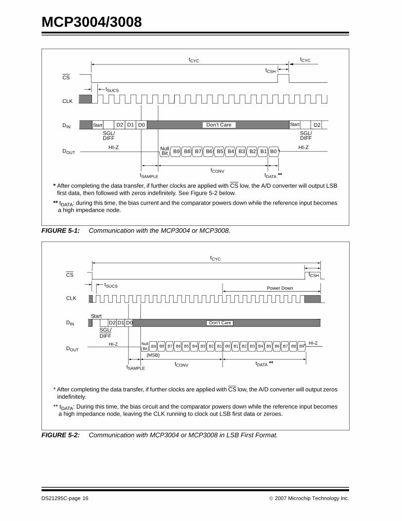
Communication with the MCP3004/3008 devices isaccomplished using a standard SPI-compatible serialinterface. Initiating communication with either device isdone by bringing the CS line low (see Figure 5-1). If thedevice was powered up with the CS pin low, it must bebrought high and back low to initiate communication.The first clock received with CS low and DIN high willconstitute a start bit. The SGL/DIFF bit follows the startbit and will determine if the conversion will be doneusing single-ended or differential input mode. The nextthree bits (D0, D1 and D2) are used to select the inputchannel configuration. Table 5-1 and Table 5-2 showthe configuration bits for the MCP3004 and MCP3008,respectively. The device will begin to sample the ana-log input on the fourth rising edge of the clock after thestart bit has been received. The sample period will endon the falling edge of the fifth clock following the startbit.
Once the D0 bit is input, one more clock is required tocomplete the sample and hold period (DIN is a “don’tcare” for this clock). On the falling edge of the nextclock, the device will output a low null bit. The next 10clocks will output the result of the conversion with MSBfirst, as shown in Figure 5-1. Data is always output fromthe device on the falling edge of the clock. If all 10 databits have been transmitted and the device continues toreceive clocks while the CS is held low, the device willoutput the conversion result LSB first, as is shown inFigure 5-2. If more clocks are provided to the devicewhile CS is still low (after the LSB first data has beentransmitted), the device will clock out zeros indefinitely.
If necessary, it is possible to bring CS low and clock inleading zeros on the DIN line before the start bit. This isoften done when dealing with microcontroller-basedSPI ports that must send 8 bits at a time. Refer toSection 6.1, “Using the MCP3004/3008 with Microcon-troller (MCU) SPI Ports”, for more details on using theMCP3004/3008 devices with hardware SPI ports.
TABLE 5-1: CONFIGURE BITS FOR THE MCP3004
TABLE 5-2: CONFIGURE BITS FOR THE MCP3008
Control Bit Selections Input
ConfigurationChannel SelectionSingle/
DiffD2* D1 D0
1 X 0 0 single-ended CH0
1 X 0 1 single-ended CH1
1 X 1 0 single-ended CH2
1 X 1 1 single-ended CH3
0 X 0 0 differential CH0 = IN+CH1 = IN-
0 X 0 1 differential CH0 = IN-CH1 = IN+
0 X 1 0 differential CH2 = IN+CH3 = IN-
0 X 1 1 differential CH2 = IN-CH3 = IN+
* D2 is “don’t care” for MCP3004
Control Bit Selections Input
ConfigurationChannel SelectionSingle
/DiffD2 D1 D0
1 0 0 0 single-ended CH0
1 0 0 1 single-ended CH1
1 0 1 0 single-ended CH2
1 0 1 1 single-ended CH3
1 1 0 0 single-ended CH4
1 1 0 1 single-ended CH5
1 1 1 0 single-ended CH6
1 1 1 1 single-ended CH7
0 0 0 0 differential CH0 = IN+CH1 = IN-
0 0 0 1 differential CH0 = IN-CH1 = IN+
0 0 1 0 differential CH2 = IN+CH3 = IN-
0 0 1 1 differential CH2 = IN-CH3 = IN+
0 1 0 0 differential CH4 = IN+CH5 = IN-
0 1 0 1 differential CH4 = IN-CH5 = IN+
0 1 1 0 differential CH6 = IN+CH7 = IN-
0 1 1 1 differential CH6 = IN-CH7 = IN+
© 2007 Microchip Technology Inc. DS21295C-page 15
MCP3004/3008
FIGURE 5-1: Communication with the MCP3004 or MCP3008.
FIGURE 5-2: Communication with MCP3004 or MCP3008 in LSB First Format.
CS
CLK
DIN
DOUT
D1D2 D0
HI-Z
Don’t Care
NullBit B9 B8 B7 B6 B5 B4 B3 B2 B1 B0 *
HI-Z
tSAMPLE
tCONV
SGL/DIFF
Start
tCYC
tCSH
tCYC
D2
SGL/DIFF
Start
* After completing the data transfer, if further clocks are applied with CS low, the A/D converter will output LSBfirst data, then followed with zeros indefinitely. See Figure 5-2 below.
** tDATA: during this time, the bias current and the comparator powers down while the reference input becomesa high impedance node.
tDATA **
tSUCS
NullBit
B9 B8 B7 B6 B5 B4 B3 B2 B1 B0 B1 B2 B3 B4 B5 B6 B7 B8 B9
CS
CLK
DOUTHI-Z HI-Z
(MSB)
tCONV tDATA **
Power Down
tSAMPLE
Start
SGL/DIFF
DIN
tCYC
tCSH
D0D1D2
* After completing the data transfer, if further clocks are applied with CS low, the A/D converter will output zerosindefinitely.
** tDATA: During this time, the bias circuit and the comparator powers down while the reference input becomesa high impedance node, leaving the CLK running to clock out LSB first data or zeroes.
tSUCS
Don’t Care
*
DS21295C-page 16 © 2007 Microchip Technology Inc.
MCP3004/3008
6.0 APPLICATIONS INFORMATION
6.1 Using the MCP3004/3008 with Microcontroller (MCU) SPI Ports
With most microcontroller SPI ports, it is required tosend groups of eight bits. It is also required that themicrocontroller SPI port be configured to clock out dataon the falling edge of clock and latch data in on the ris-ing edge. Because communication with the MCP3004/3008 devices may not need multiples of eight clocks, itwill be necessary to provide more clocks than arerequired. This is usually done by sending ‘leadingzeros’ before the start bit. As an example, Figure 6-1and Figure 6-2 shows how the MCP3004/3008 can beinterfaced to a MCU with a hardware SPI port.Figure 6-1 depicts the operation shown in SPI Mode0,0, which requires that the SCLK from the MCU idlesin the ‘low’ state, while Figure 6-2 shows the similarcase of SPI Mode 1,1, where the clock idles in the ‘high’state.
As is shown in Figure 6-1, the first byte transmitted tothe A/D converter contains seven leading zeros beforethe start bit. Arranging the leading zeros this wayinduces the 10 data bits to fall in positions easily manip-ulated by the MCU. The MSB is clocked out of the A/Dconverter on the falling edge of clock number 14. Oncethe second eight clocks have been sent to the device,the MCU receive buffer will contain five unknown bits(the output is at high impedance for the first twoclocks), the null bit and the highest order 2 bits of theconversion. Once the third byte has been sent to thedevice, the receive register will contain the lowest ordereight bits of the conversion results. Employing thismethod ensures simpler manipulation of the converteddata.
Figure 6-2 shows the same thing in SPI Mode 1,1,which requires that the clock idles in the high state. Aswith mode 0,0, the A/D converter outputs data on thefalling edge of the clock and the MCU latches data fromthe A/D converter in on the rising edge of the clock.
© 2007 Microchip Technology Inc. DS21295C-page 17

MCP3004/3008
FIGURE 6-1: SPI Communication with the MCP3004/3008 using 8-bit segments (Mode 0,0: SCLK idles low).
FIGURE 6-2: SPI Communication with the MCP3004/3008 using 8-bit segments (Mode 1,1: SCLK idles high).
1 2 3 4 5 6 7 8 9 10 11 12 13 14 15 16
CS
SCLK
DIN
X = “Don’t Care” Bits
17 18 19 20 21 22 23 24
DOUT
NULLBIT B9 B8 B7 B6 B5 B4 B3 B2 B1 B0HI-Z
MCU latches data from A/D
Data is clocked out ofA/D converter on falling edges
converter on rising edges of SCLK
Don’t CareSGL/DIFF
D1D2Start
0 0 0 0 0 1 X X X XDO X X X X X X X X
B7 B6 B5 B4 B3 B2 B1 B0B9 B80? ? ? ? ? ? ? ? ? ?
D1D2SGL/DIFF
StartBit
(Null)
MCU Transmitted Data(Aligned with fallingedge of clock)
MCU Received Data(Aligned with risingedge of clock)
Data stored into MCU receive register after transmission of first 8 bits
Data stored into MCU receive register after transmission of second 8 bits
Data stored into MCU receive register after transmission of last 8 bits
DO
??
0 0
?
MCU Transmitted Data
1 2 3 4 5 6 7 8 9 10 11 12 13 14 15 16
CS
SCLK
DIN
X = “Don’t Care” Bits
17 18 19 20 21 22 23 24
DOUT
DO Don’t Care
NULLBIT B9 B8 B6 B5 B4 B3 B2 B1 B0HI-Z
0 0 0 0 0 1 X X X XDO
SGL/DIFF
X X X X X X X X
B7 B6 B5 B4 B3 B2 B1 B0B9 B80? ? ? ? ? ? ? ? ? ? ?
MCU latches data from A/D converter on rising edges of SCLK
Data is clocked out of A/D converter on falling edges
D1D2SGL/DIFF
StartBit
(Null)
D1D2Start
MCU Transmitted Data(Aligned with fallingedge of clock)
MCU Received Data(Aligned with risingedge of clock)
B7
Data stored into MCU receive register after transmission of first 8 bits
Data stored into MCU receive register after transmission of second 8 bits
Data stored into MCU receive register after transmission of last 8 bits
??
0 0
DS21295C-page 18 © 2007 Microchip Technology Inc.

MCP3004/3008
6.2 Maintaining Minimum Clock Speed
When the MCP3004/3008 initiates the sample period,charge is stored on the sample capacitor. When thesample period is complete, the device converts one bitfor each clock that is received. It is important for theuser to note that a slow clock rate will allow charge tobleed off the sample capacitor while the conversion istaking place. At 85°C (worst case condition), the partwill maintain proper charge on the sample capacitor forat least 1.2 ms after the sample period has ended. Thismeans that the time between the end of the sampleperiod and the time that all 10 data bits have beenclocked out must not exceed 1.2 ms (effective clockfrequency of 10 kHz). Failure to meet this criterion mayintroduce linearity errors into the conversion outsidethe rated specifications. It should be noted that duringthe entire conversion cycle, the A/D converter does notrequire a constant clock speed or duty cycle, as long asall timing specifications are met.
6.3 Buffering/Filtering the Analog Inputs
If the signal source for the A/D converter is not a lowimpedance source, it will have to be buffered or inaccu-rate conversion results may occur (see Figure 4-2). It isalso recommended that a filter be used to eliminate anysignals that may be aliased back in to the conversionresults, as is illustrated in Figure 6-3, where an op ampis used to drive, filter and gain the analog input of theMCP3004/3008. This amplifier provides a low imped-ance source for the converter input, plus a low passfilter, which eliminates unwanted high frequency noise.
Low pass (anti-aliasing) filters can be designed usingMicrochip’s free interactive FilterLab™ software. Filter-Lab will calculate capacitor and resistors values, aswell as determine the number of poles that are requiredfor the application. For more information on filtering sig-nals, see AN699, “Anti-Aliasing Analog Filters for DataAcquisition Systems”.
FIGURE 6-3: The MCP601 Operational Amplifier is used to implement a second order anti-aliasing filter for the signal being converted by the MCP3004.
6.4 Layout ConsiderationsWhen laying out a printed circuit board for use withanalog components, care should be taken to reducenoise wherever possible. A bypass capacitor shouldalways be used with this device and should be placedas close as possible to the device pin. A bypass capac-itor value of 1 µF is recommended.
Digital and analog traces should be separated as muchas possible on the board, with no traces running under-neath the device or bypass capacitor. Extra precau-tions should be taken to keep traces with highfrequency signals (such as clock lines) as far as possi-ble from analog traces.
Use of an analog ground plane is recommended inorder to keep the ground potential the same for alldevices on the board. Providing VDD connections todevices in a “star” configuration can also reduce noiseby eliminating return current paths and associatederrors (see Figure 6-4). For more information on layouttips when using A/D converters, refer to AN688, “Lay-out Tips for 12-Bit A/D Converter Applications”.
FIGURE 6-4: VDD traces arranged in a ‘Star’ configuration in order to reduce errors caused by current return paths.
MCP3004
VDD
10 µF
IN-
IN+
-
+VIN
C1
C2
VREF
4.096VReference
1 µF
1 µF0.1 µF
MCP601R1
R2
R3R4
MCP1541
VDD
Connection
Device 1
Device 2
Device 3
Device 4
© 2007 Microchip Technology Inc. DS21295C-page 19

MCP3004/3008
6.5 Utilizing the Digital and Analog Ground Pins
The MCP3004/3008 devices provide both digital andanalog ground connections to provide additionalmeans of noise reduction. As is shown in Figure 6-5,the analog and digital circuitry is separated internal tothe device. This reduces noise from the digital portionof the device being coupled into the analog portion ofthe device. The two grounds are connected internallythrough the substrate which has a resistance of 5 -10Ω.
If no ground plane is utilized, both grounds must beconnected to VSS on the board. If a ground plane isavailable, both digital and analog ground pins shouldbe connected to the analog ground plane. If both ananalog and a digital ground plane are available, boththe digital and the analog ground pins should be con-nected to the analog ground plane. Following thesesteps will reduce the amount of digital noise from therest of the board being coupled into the A/D converter.
FIGURE 6-5: Separation of Analog and Digital Ground Pins.
MCP3004/08
Analog Ground Plane
DGND AGND
VDD
0.1 µF
Substrate
5 - 10Ω
Digital Side
-SPI Interface-Shift Register-Control Logic
Analog Side
-Sample Cap-Capacitor Array-Comparator
DS21295C-page 20 © 2007 Microchip Technology Inc.

MCP3004/3008
7.0 PACKAGING INFORMATION
7.1 Package Marking Information
Legend: XX...X Customer-specific informationY Year code (last digit of calendar year)YY Year code (last 2 digits of calendar year)WW Week code (week of January 1 is week ‘01’)NNN Alphanumeric traceability code Pb-free JEDEC designator for Matte Tin (Sn)* This package is Pb-free. The Pb-free JEDEC designator ( )
can be found on the outer packaging for this package.
Note: In the event the full Microchip part number cannot be marked on one line, it willbe carried over to the next line, thus limiting the number of available charactersfor customer-specific information.
3e
3e
14-Lead PDIP (300 mil) Example:
14-Lead SOIC (150 mil) Example:
XXXXXXXXXXXXXXXXXXXXXXXXXXXX
YYWWNNN
XXXXXXXXXXX
YYWWNNN
MCP3004-I/P
0712027
XXXXXXXXXXXMCP3004ISL
0712027
XXXXXXXXXXX
XXXXXXXX
NNN
YYWW
14-Lead TSSOP (4.4mm) * Example:
3004
027
0712
3e
3e
3e
© 2007 Microchip Technology Inc. DS21295C-page 21

MCP3004/3008
Package Marking Information (Continued)
16-Lead PDIP (300 mil) (MCP3308) Example:
16-Lead SOIC (150 mil) (MCP3308) Example:
XXXXXXXXXXXXXXXXXXXXXXXXXXXX
YYWWNNN
XXXXXXXXXXXXX
YYWWNNN
MCP3008-I/P
0712030
XXXXXXXXXXXXXMCP3008-I/SL
0712030
XXXXXXXXXX
3e
3e
DS21295C-page 22 © 2007 Microchip Technology Inc.

MCP3004/3008
14-Lead Plastic Dual In-Line (P) – 300 mil Body [PDIP]
Notes:1. Pin 1 visual index feature may vary, but must be located with the hatched area.2. § Significant Characteristic.3. Dimensions D and E1 do not include mold flash or protrusions. Mold flash or protrusions shall not exceed .010" per side.4. Dimensioning and tolerancing per ASME Y14.5M.
BSC: Basic Dimension. Theoretically exact value shown without tolerances.
Note: For the most current package drawings, please see the Microchip Packaging Specification located at http://www.microchip.com/packaging
Units INCHES
Dimension Limits MIN NOM MAX
Number of Pins N 14
Pitch e .100 BSC
Top to Seating Plane A – – .210
Molded Package Thickness A2 .115 .130 .195
Base to Seating Plane A1 .015 – –
Shoulder to Shoulder Width E .290 .310 .325
Molded Package Width E1 .240 .250 .280
Overall Length D .735 .750 .775
Tip to Seating Plane L .115 .130 .150
Lead Thickness c .008 .010 .015
Upper Lead Width b1 .045 .060 .070
Lower Lead Width b .014 .018 .022
Overall Row Spacing § eB – – .430
N
E1
D
NOTE 1
1 2 3
E
c
eB
A2
L
A
A1b1
b e
Microchip Technology Drawing C04-005B
© 2007 Microchip Technology Inc. DS21295C-page 23

MCP3004/3008
14-Lead Plastic Small Outline (SL) – Narrow, 3.90 mm Body [SOIC]
Notes:1. Pin 1 visual index feature may vary, but must be located within the hatched area.2. § Significant Characteristic.3. Dimensions D and E1 do not include mold flash or protrusions. Mold flash or protrusions shall not exceed 0.15 mm per side.4. Dimensioning and tolerancing per ASME Y14.5M.
BSC: Basic Dimension. Theoretically exact value shown without tolerances.REF: Reference Dimension, usually without tolerance, for information purposes only.
Note: For the most current package drawings, please see the Microchip Packaging Specification located at http://www.microchip.com/packaging
Units MILLMETERS
Dimension Limits MIN NOM MAX
Number of Pins N 14
Pitch e 1.27 BSC
Overall Height A – – 1.75
Molded Package Thickness A2 1.25 – –
Standoff § A1 0.10 – 0.25
Overall Width E 6.00 BSC
Molded Package Width E1 3.90 BSC
Overall Length D 8.65 BSC
Chamfer (optional) h 0.25 – 0.50
Foot Length L 0.40 – 1.27
Footprint L1 1.04 REF
Foot Angle φ 0° – 8°
Lead Thickness c 0.17 – 0.25
Lead Width b 0.31 – 0.51
Mold Draft Angle Top α 5° – 15°
Mold Draft Angle Bottom β 5° – 15°
NOTE 1
N
D
E
E1
1 2 3
b
e
A
A1
A2
L
L1
c
h
hα
β
φ
Microchip Technology Drawing C04-065B
DS21295C-page 24 © 2007 Microchip Technology Inc.

MCP3004/3008
14-Lead Plastic Thin Shrink Small Outline (ST) – 4.4 mm Body [TSSOP]
Notes:1. Pin 1 visual index feature may vary, but must be located within the hatched area.2. Dimensions D and E1 do not include mold flash or protrusions. Mold flash or protrusions shall not exceed 0.15 mm per side.3. Dimensioning and tolerancing per ASME Y14.5M.
BSC: Basic Dimension. Theoretically exact value shown without tolerances.REF: Reference Dimension, usually without tolerance, for information purposes only.
Note: For the most current package drawings, please see the Microchip Packaging Specification located at http://www.microchip.com/packaging
Units MILLIMETERS
Dimension Limits MIN NOM MAX
Number of Pins N 14
Pitch e 0.65 BSC
Overall Height A – – 1.20
Molded Package Thickness A2 0.80 1.00 1.05
Standoff A1 0.05 – 0.15
Overall Width E 6.40 BSC
Molded Package Width E1 4.30 4.40 4.50
Molded Package Length D 4.90 5.00 5.10
Foot Length L 0.45 0.60 0.75
Footprint L1 1.00 REF
Foot Angle φ 0° – 8°
Lead Thickness c 0.09 – 0.20
Lead Width b 0.19 – 0.30
NOTE 1
D
N
E
E1
1 2
e
b
c
A
A1
A2
L1 L
φ
Microchip Technology Drawing C04-087B
© 2007 Microchip Technology Inc. DS21295C-page 25

MCP3004/3008
16-Lead Plastic Dual In-Line (P) – 300 mil Body [PDIP]
Notes:1. Pin 1 visual index feature may vary, but must be located within the hatched area.2. § Significant Characteristic.3. Dimensions D and E1 do not include mold flash or protrusions. Mold flash or protrusions shall not exceed .010" per side.4. Dimensioning and tolerancing per ASME Y14.5M.
BSC: Basic Dimension. Theoretically exact value shown without tolerances.
Note: For the most current package drawings, please see the Microchip Packaging Specification located at http://www.microchip.com/packaging
Units INCHES
Dimension Limits MIN NOM MAX
Number of Pins N 16
Pitch e .100 BSC
Top to Seating Plane A – – .210
Molded Package Thickness A2 .115 .130 .195
Base to Seating Plane A1 .015 – –
Shoulder to Shoulder Width E .290 .310 .325
Molded Package Width E1 .240 .250 .280
Overall Length D .735 .755 .775
Tip to Seating Plane L .115 .130 .150
Lead Thickness c .008 .010 .015
Upper Lead Width b1 .045 .060 .070
Lower Lead Width b .014 .018 .022
Overall Row Spacing § eB – – .430
N
E1NOTE 1
D
1 2 3
A
A1b1
b e
L
A2
E
eB
c
Microchip Technology Drawing C04-017B
DS21295C-page 26 © 2007 Microchip Technology Inc.

MCP3004/3008
16-Lead Plastic Small Outline (SL) – Narrow, 3.90 mm Body [SOIC]
Notes:1. Pin 1 visual index feature may vary, but must be located within the hatched area.2. § Significant Characteristic.3. Dimensions D and E1 do not include mold flash or protrusions. Mold flash or protrusions shall not exceed 0.15 mm per side.4. Dimensioning and tolerancing per ASME Y14.5M.
BSC: Basic Dimension. Theoretically exact value shown without tolerances.REF: Reference Dimension, usually without tolerance, for information purposes only.
Note: For the most current package drawings, please see the Microchip Packaging Specification located at http://www.microchip.com/packaging
Units MILLMETERS
Dimension Limits MIN NOM MAX
Number of Pins N 16
Pitch e 1.27 BSC
Overall Height A – – 1.75
Molded Package Thickness A2 1.25 – –
Standoff § A1 0.10 – 0.25
Overall Width E 6.00 BSC
Molded Package Width E1 3.90 BSC
Overall Length D 9.90 BSC
Chamfer (optional) h 0.25 – 0.50
Foot Length L 0.40 – 1.27
Footprint L1 1.04 REF
Foot Angle φ 0° – 8°
Lead Thickness c 0.17 – 0.25
Lead Width b 0.31 – 0.51
Mold Draft Angle Top α 5° – 15°
Mold Draft Angle Bottom β 5° – 15°
D
E
E1
N
NOTE 1
1 2 3
b
e
h
h
c
L
L1
A2A
A1β
φ
α
Microchip Technology Drawing C04-108B
© 2007 Microchip Technology Inc. DS21295C-page 27

MCP3004/3008
NOTES:
DS21295C-page 28 © 2007 Microchip Technology Inc.

MCP3004/3008
APPENDIX A: REVISION HISTORY
Revision C (January 2007)
This revision includes updates to the packaging diagrams.
© 2007 Microchip Technology Inc. DS21295C-page 29

MCP3004/3008
NOTES:
DS21295C-page 30 © 2007 Microchip Technology Inc.

MCP3004/3008
PRODUCT IDENTIFICATION SYSTEMTo order or obtain information, e.g., on pricing or delivery, refer to the factory or the listed sales office.
Device: MCP3004: 4-Channel 10-Bit Serial A/D ConverterMCP3004T: 4-Channel 10-Bit Serial A/D Converter
(Tape and Reel)MCP3008: 8-Channel 10-Bit Serial A/D ConverterMCP3008T: 8-Channel 10-Bit Serial A/D Converter
(Tape and Reel)
Temperature Range: I = -40°C to +85°C
Package: P = Plastic DIP (300 mil Body), 14-lead, 16-leadSL = Plastic SOIC (150 mil Body), 14-lead, 16-leadST = Plastic TSSOP (4.4mm), 14-lead
Examples:
a) MCP3004-I/P: Industrial Temperature, PDIP package.
b) MCP3004-I/SL: Industrial Temperature, SOIC package.
c) MCP3004-I/ST: Industrial Temperature, TSSOP package.
d) MCP3004T-I/ST: Industrial Temperature,TSSOP package, Tape and Reel.
a) MCP3008-I/P: Industrial Temperature, PDIP package.
b) MCP3008-I/SL: Industrial Temperature, SOIC package.
PART NO. X /XX
PackageTemperatureRange
Device
© 2007 Microchip Technology Inc. DS21295C-page31

MCP3004/3008
NOTES:
DS21295C-page 32 © 2007 Microchip Technology Inc.

Note the following details of the code protection feature on Microchip devices:
• Microchip products meet the specification contained in their particular Microchip Data Sheet.
• Microchip believes that its family of products is one of the most secure families of its kind on the market today, when used in the intended manner and under normal conditions.
• There are dishonest and possibly illegal methods used to breach the code protection feature. All of these methods, to our knowledge, require using the Microchip products in a manner outside the operating specifications contained in Microchip’s Data Sheets. Most likely, the person doing so is engaged in theft of intellectual property.
• Microchip is willing to work with the customer who is concerned about the integrity of their code.
• Neither Microchip nor any other semiconductor manufacturer can guarantee the security of their code. Code protection does not mean that we are guaranteeing the product as “unbreakable.”
Code protection is constantly evolving. We at Microchip are committed to continuously improving the code protection features of ourproducts. Attempts to break Microchip’s code protection feature may be a violation of the Digital Millennium Copyright Act. If such actsallow unauthorized access to your software or other copyrighted work, you may have a right to sue for relief under that Act.
Information contained in this publication regarding deviceapplications and the like is provided only for your convenienceand may be superseded by updates. It is your responsibility toensure that your application meets with your specifications.MICROCHIP MAKES NO REPRESENTATIONS ORWARRANTIES OF ANY KIND WHETHER EXPRESS ORIMPLIED, WRITTEN OR ORAL, STATUTORY OROTHERWISE, RELATED TO THE INFORMATION,INCLUDING BUT NOT LIMITED TO ITS CONDITION,QUALITY, PERFORMANCE, MERCHANTABILITY ORFITNESS FOR PURPOSE. Microchip disclaims all liabilityarising from this information and its use. Use of Microchipdevices in life support and/or safety applications is entirely atthe buyer’s risk, and the buyer agrees to defend, indemnify andhold harmless Microchip from any and all damages, claims,suits, or expenses resulting from such use. No licenses areconveyed, implicitly or otherwise, under any Microchipintellectual property rights.
© 2007 Microchip Technology Inc.
Trademarks
The Microchip name and logo, the Microchip logo, Accuron, dsPIC, KEELOQ, microID, MPLAB, PIC, PICmicro, PICSTART, PRO MATE, PowerSmart, rfPIC, and SmartShunt are registered trademarks of Microchip Technology Incorporated in the U.S.A. and other countries.
AmpLab, FilterLab, Migratable Memory, MXDEV, MXLAB, SEEVAL, SmartSensor and The Embedded Control Solutions Company are registered trademarks of Microchip Technology Incorporated in the U.S.A.
Analog-for-the-Digital Age, Application Maestro, CodeGuard, dsPICDEM, dsPICDEM.net, dsPICworks, ECAN, ECONOMONITOR, FanSense, FlexROM, fuzzyLAB, In-Circuit Serial Programming, ICSP, ICEPIC, Linear Active Thermistor, Mindi, MiWi, MPASM, MPLIB, MPLINK, PICkit, PICDEM, PICDEM.net, PICLAB, PICtail, PowerCal, PowerInfo, PowerMate, PowerTool, REAL ICE, rfLAB, rfPICDEM, Select Mode, Smart Serial, SmartTel, Total Endurance, UNI/O, WiperLock and ZENA are trademarks of Microchip Technology Incorporated in the U.S.A. and other countries.
SQTP is a service mark of Microchip Technology Incorporated in the U.S.A.
All other trademarks mentioned herein are property of their respective companies.
© 2007, Microchip Technology Incorporated, Printed in the U.S.A., All Rights Reserved.
Printed on recycled paper.
DS21295C-page 33
Microchip received ISO/TS-16949:2002 certification for its worldwide headquarters, design and wafer fabrication facilities in Chandler and Tempe, Arizona, Gresham, Oregon and Mountain View, California. The Company’s quality system processes and procedures are for its PIC®
MCUs and dsPIC DSCs, KEELOQ® code hopping devices, Serial EEPROMs, microperipherals, nonvolatile memory and analog products. In addition, Microchip’s quality system for the design and manufacture of development systems is ISO 9001:2000 certified.

DS21295C-page 34 © 2007 Microchip Technology Inc.
AMERICASCorporate Office2355 West Chandler Blvd.Chandler, AZ 85224-6199Tel: 480-792-7200 Fax: 480-792-7277Technical Support: http://support.microchip.comWeb Address: www.microchip.com
AtlantaDuluth, GA Tel: 678-957-9614 Fax: 678-957-1455
BostonWestborough, MA Tel: 774-760-0087 Fax: 774-760-0088
ChicagoItasca, IL Tel: 630-285-0071 Fax: 630-285-0075
DallasAddison, TX Tel: 972-818-7423 Fax: 972-818-2924
DetroitFarmington Hills, MI Tel: 248-538-2250Fax: 248-538-2260
KokomoKokomo, IN Tel: 765-864-8360Fax: 765-864-8387
Los AngelesMission Viejo, CA Tel: 949-462-9523 Fax: 949-462-9608
Santa ClaraSanta Clara, CA Tel: 408-961-6444Fax: 408-961-6445
TorontoMississauga, Ontario, CanadaTel: 905-673-0699 Fax: 905-673-6509
ASIA/PACIFICAsia Pacific OfficeSuites 3707-14, 37th FloorTower 6, The GatewayHabour City, KowloonHong KongTel: 852-2401-1200Fax: 852-2401-3431
Australia - SydneyTel: 61-2-9868-6733Fax: 61-2-9868-6755
China - BeijingTel: 86-10-8528-2100 Fax: 86-10-8528-2104
China - ChengduTel: 86-28-8665-5511Fax: 86-28-8665-7889
China - FuzhouTel: 86-591-8750-3506 Fax: 86-591-8750-3521
China - Hong Kong SARTel: 852-2401-1200 Fax: 852-2401-3431
China - QingdaoTel: 86-532-8502-7355Fax: 86-532-8502-7205
China - ShanghaiTel: 86-21-5407-5533 Fax: 86-21-5407-5066
China - ShenyangTel: 86-24-2334-2829Fax: 86-24-2334-2393
China - ShenzhenTel: 86-755-8203-2660 Fax: 86-755-8203-1760
China - ShundeTel: 86-757-2839-5507 Fax: 86-757-2839-5571
China - WuhanTel: 86-27-5980-5300Fax: 86-27-5980-5118
China - XianTel: 86-29-8833-7250Fax: 86-29-8833-7256
ASIA/PACIFICIndia - BangaloreTel: 91-80-4182-8400 Fax: 91-80-4182-8422
India - New DelhiTel: 91-11-4160-8631Fax: 91-11-4160-8632
India - PuneTel: 91-20-2566-1512Fax: 91-20-2566-1513
Japan - YokohamaTel: 81-45-471- 6166 Fax: 81-45-471-6122
Korea - GumiTel: 82-54-473-4301Fax: 82-54-473-4302
Korea - SeoulTel: 82-2-554-7200Fax: 82-2-558-5932 or 82-2-558-5934
Malaysia - PenangTel: 60-4-646-8870Fax: 60-4-646-5086
Philippines - ManilaTel: 63-2-634-9065Fax: 63-2-634-9069
SingaporeTel: 65-6334-8870Fax: 65-6334-8850
Taiwan - Hsin ChuTel: 886-3-572-9526Fax: 886-3-572-6459
Taiwan - KaohsiungTel: 886-7-536-4818Fax: 886-7-536-4803
Taiwan - TaipeiTel: 886-2-2500-6610 Fax: 886-2-2508-0102
Thailand - BangkokTel: 66-2-694-1351Fax: 66-2-694-1350
EUROPEAustria - WelsTel: 43-7242-2244-39Fax: 43-7242-2244-393Denmark - CopenhagenTel: 45-4450-2828 Fax: 45-4485-2829
France - ParisTel: 33-1-69-53-63-20 Fax: 33-1-69-30-90-79
Germany - MunichTel: 49-89-627-144-0 Fax: 49-89-627-144-44
Italy - Milan Tel: 39-0331-742611 Fax: 39-0331-466781
Netherlands - DrunenTel: 31-416-690399 Fax: 31-416-690340
Spain - MadridTel: 34-91-708-08-90Fax: 34-91-708-08-91
UK - WokinghamTel: 44-118-921-5869Fax: 44-118-921-5820
WORLDWIDE SALES AND SERVICE
12/08/06