Embed Size (px)
Citation preview
70
MORPHOLOGY DEVELOPMENT OF NORMAL BLENDS,MICROFIBRILLAR BLENDS AND COMPOSITES FROM LDPE AND PET
Jayanarayanan K1, Gejo George2, Sabu Thomas3, *Kuruvilla Joseph4
ABSTRACT
In this work, the morphology of the normal blends, microfibrillar blends andthe corresponding microfibrillar composites based on low density polyethylene andpoly ethylene terephthalate was analysed. The effect of poly ethylene terephthalateconcentration on the size of the dispersed phase was studied. With the increase inPET concentration an increase in the diameter of poly ethylene terephthalate spheres/fibrils was observed. The poly ethylene terephthalate fibrils with relatively uniformdiameter distribution was obtained for 85/15 and 75/25 w/w% blends. The increase inpoly ethylene terephthalate concentration developed co continuous morphology in thecase of normal blends. The fibrillar morphology of poly ethylene terephthalate wasperturbed at its higher concentrations in the case of microfibrillar composites.
Keywords: LDPE, PET, Microfibrillar composites, Morphology, Scanning electronmicroscopy.
INTRODUCTION
Immiscible blends have been considered undesirable for much of their historyon account of the weak inter phase boundaries producing poor mechanical properties.One method of overcoming the problem of immiscibility is to produce tailored blendmorphology able to negate its effects (Li et al. 2002, Yang et al. 1998, Migler 2001).The lack of chemical interaction between the blend constituents is generally consid-ered a disadvantage for traditional polymer blending, whereas it is a critical element inthe successful creation of a new type of fibrillar polymer - polymer composite fromimmiscible blends. Microfibrillar reinforced composites (MFCs) are comprised of an
1 Department of Chemical Engineering and Materials Science, Amrita Vishwa Vidyapeetham,Coimbatore, Tamil Nadu - 641105, India2 Research and Post Graduate Department of Chemistry, St. Berchmans College, Changanassery,Kerala - 686101, India3 School of Chemical Sciences, Mahatma Gandhi University, Priyadarshini Hills P.O, Kottayam,Kerala - 686560, India4 Department of Chemistry, Indian Institute of Space Science and Technology, ISRO P.O,Thiruvananthapuram, Kerala - 695022, India* Corresponding author: [email protected]
ISSN: 0973-7464 Vol. XVI: No.1 & 2 SB Academic Review2009: 66-76

71
isotropic polymer matrix reinforced with an even dispersion of high aspect ratio microor nanofibrils, made from the secondary dispersed polymer after the blend has under-gone strengthening via alignment and stretching of its molecular chains through amechanical process. Depending upon the method of post-processing during which thematrix polymer is remelted into a continuous phase, the final structure of an MFC canexhibit both quasi isotropic behaviour as well as varying degrees of anisotropy (Fuchset al. 2006).
Interestingly, MFCs from condensation polymers have been reported to ex-hibit a self compatibilization phenomenon that means they do not require these extraadditives or treatments to create the desired copolymeric interface. Additional con-densation and transreactions that occur in the melt (Flory 1953) and the bulk solidstate (Fakirov 1990) are the causes of this favourable reaction, and thus the usualproblems associated with a poor matrix reinforcement interface are somewhat allevi-ated (Fakirov and Evstatiev 1994). This occurrence is especially significant givenreports that the use of a compatibiliser may actually inhibit the formation of highaspect ratio microfibrils by impeding the main mechanism behind their formation, namelythe coalescence of adjacent dispersed particles of the reinforcing polymer (Fuchs etal. 2006).
A lot of studies have shown that an elongational flow filed and a small viscos-ity ratio (usually less than 1) can facilitate the fibrillation of the dispersed phase in thepolymer blends (Favis 1999, Grace 1982, Dreal et al. 1983, Dlaby et al. 1996) andmicrofibrillar blends (Li et al. 2002, Lin and Cheung 2003). In practice, especially inthe case of microfibrillar composites it has been demonstrated that even at higherviscosity ratios fibrillation of the dispersed phase can be achieved (Li et al. 2003,Leung et al. 2008).
In this work, the morphology development of LDPE/PET blends at varyingPET concentrations is studied. The morphology of the normal blends, microfibrillarblends and microfibrillar composites are analysed during the different stages of theirpreparation.
MATERIALS AND METHODS
LDPE used in this study was Relene-16MA 400, Reliance India, with an MFIof 30 g/10 min. The other properties are listed in Table1.
ISSN: 0973-7464 Vol. XVI: No.1 & 2 SB Academic Review 2009: 66-76
72
Property Value
Specific gravity 0.91
Ultimate Tensile strength* 7.9 MPa
Tensile modulus* 102.3 MPa
Elongation at break* 111 %
Melting point 116.3°C
Property Value
Bulk density 0.83g/cc
Intrinsic viscosity 0.81dL/g
Acetaldehyde content 0.87ppm
Tensile strength* 61.7 MPa
Elongation at break* 24.7 %
Melting point** 246.5°C
Table1: Properties of LDPE
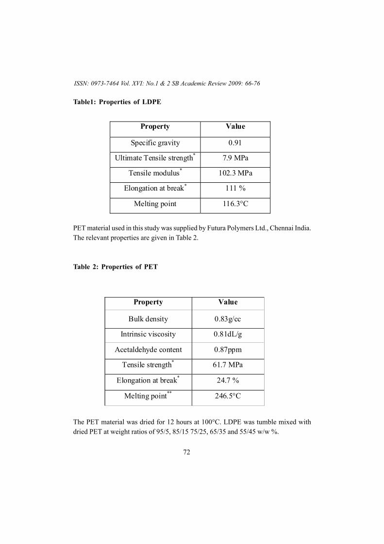
PET material used in this study was supplied by Futura Polymers Ltd., Chennai India.The relevant properties are given in Table 2.
Table 2: Properties of PET
The PET material was dried for 12 hours at 100°C. LDPE was tumble mixed withdried PET at weight ratios of 95/5, 85/15 75/25, 65/35 and 55/45 w/w %.
ISSN: 0973-7464 Vol. XVI: No.1 & 2 SB Academic Review 2009: 66-76
73
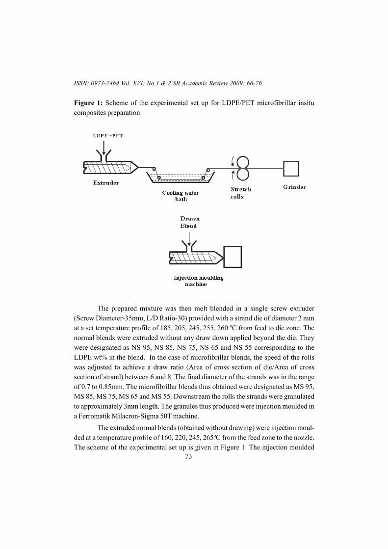
Figure 1: Scheme of the experimental set up for LDPE/PET microfibrillar insitucomposites preparation
The prepared mixture was then melt blended in a single screw extruder(Screw Diameter-35mm, L/D Ratio-30) provided with a strand die of diameter 2 mmat a set temperature profile of 185, 205, 245, 255, 260 ºC from feed to die zone. Thenormal blends were extruded without any draw down applied beyond the die. Theywere designated as NS 95, NS 85, NS 75, NS 65 and NS 55 corresponding to theLDPE wt% in the blend. In the case of microfibrillar blends, the speed of the rollswas adjusted to achieve a draw ratio (Area of cross section of die/Area of crosssection of strand) between 6 and 8. The final diameter of the strands was in the rangeof 0.7 to 0.85mm. The microfibrillar blends thus obtained were designated as MS 95,MS 85, MS 75, MS 65 and MS 55. Downstream the rolls the strands were granulatedto approximately 3mm length. The granules thus produced were injection moulded ina Ferromatik Milacron-Sigma 50T machine.
The extruded normal blends (obtained without drawing) were injection moul-ded at a temperature profile of 160, 220, 245, 265ºC from the feed zone to the nozzle.The scheme of the experimental set up is given in Figure 1. The injection moulded
ISSN: 0973-7464 Vol. XVI: No.1 & 2 SB Academic Review 2009: 66-76
74
normal neat blends were designated as NM 95, NM 85, NM 75, NM 65 and NM 55.All the drawn blends were injection moulded at a set temperature profile of 130, 160,180, 200 ºC from the feed zone to the nozzle to preserve the fibrillar nature of PET.The samples obtained were designated as MM 95, MM 85, MM 75, MM 65 and MM 55.
A JEOL JSM 840 SEM with an acceleration voltage of 20 kV was used forstudying the morphology of the specimens. To extract the PET phase from the speci-mens, a mixture of phenol/1,1,2,2, tetra chloroethane in 60/40 wt% was used as thesolvent. Similarly, to remove PP and retain the PET fibrils the specimens were treatedwith hot xylene. All the specimens were coated with a thin gold layer prior to SEManalysis. The diameter of about 100 fibrils was measured from the micrographs usingimage analysis software.
RESULTS AND DISCUSSION
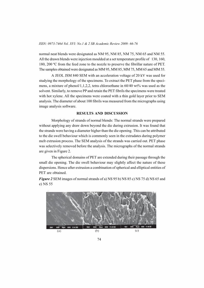
Morphology of strands of normal blends: The normal strands were preparedwithout applying any draw down beyond the die during extrusion. It was found thatthe strands were having a diameter higher than the die opening. This can be attributedto the die swell behaviour which is commonly seen in the extrudates during polymermelt extrusion process. The SEM analysis of the strands was carried out. PET phasewas selectively removed before the analysis. The micrographs of the normal strandsare given in Figure 2.
The spherical domains of PET are extended during their passage through thesmall die opening. The die swell behaviour may slightly affect the nature of thesedispersions. Hence after extrusion a combination of spherical and elliptical entities ofPET are obtained.Figure 2 SEM images of normal strands of a) NS 95 b) NS 85 c) NS 75 d) NS 65 ande) NS 55
ISSN: 0973-7464 Vol. XVI: No.1 & 2 SB Academic Review 2009: 66-76
75
(d) (e)
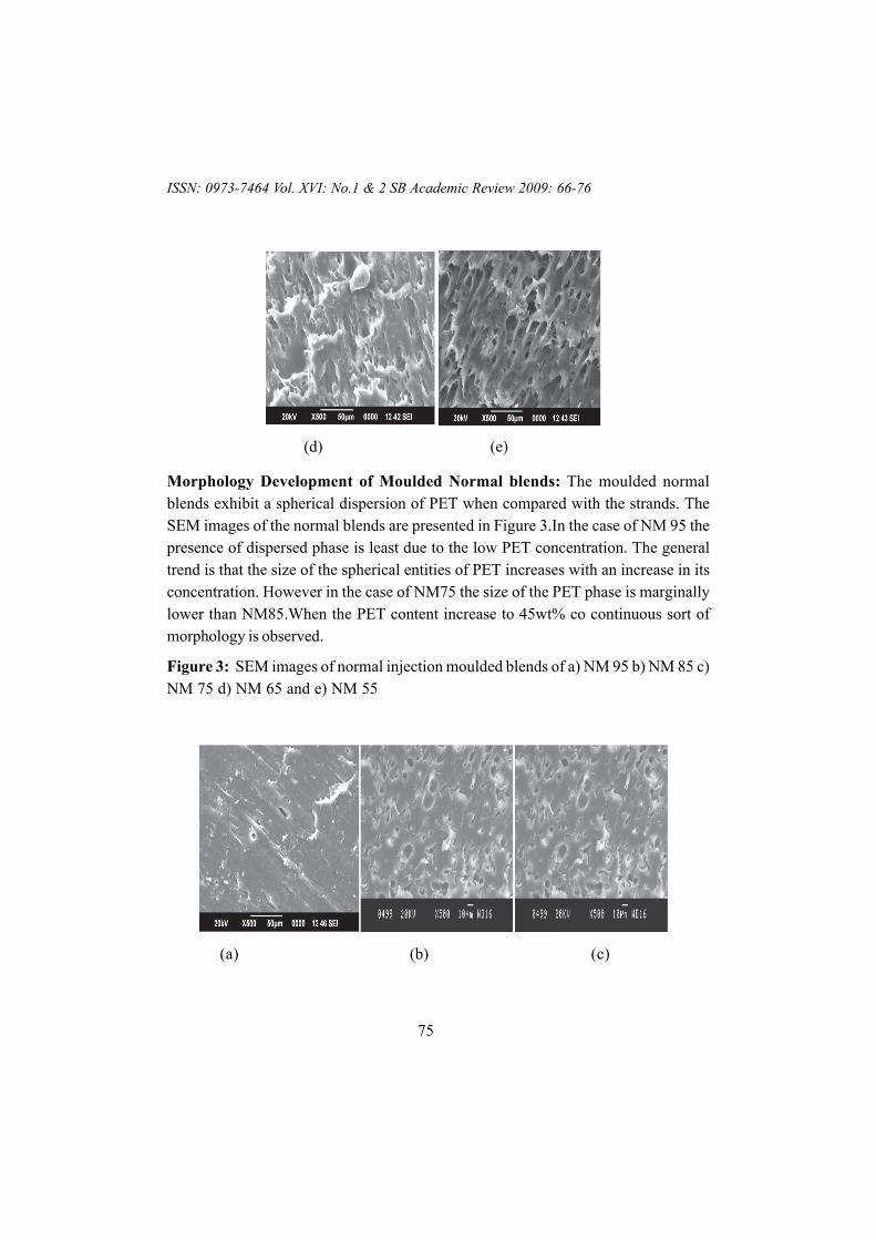
Morphology Development of Moulded Normal blends: The moulded normalblends exhibit a spherical dispersion of PET when compared with the strands. TheSEM images of the normal blends are presented in Figure 3.In the case of NM 95 thepresence of dispersed phase is least due to the low PET concentration. The generaltrend is that the size of the spherical entities of PET increases with an increase in itsconcentration. However in the case of NM75 the size of the PET phase is marginallylower than NM85.When the PET content increase to 45wt% co continuous sort ofmorphology is observed.
Figure 3: SEM images of normal injection moulded blends of a) NM 95 b) NM 85 c)NM 75 d) NM 65 and e) NM 55
(a) (b) (c)
ISSN: 0973-7464 Vol. XVI: No.1 & 2 SB Academic Review 2009: 66-76
76
(d) (e)
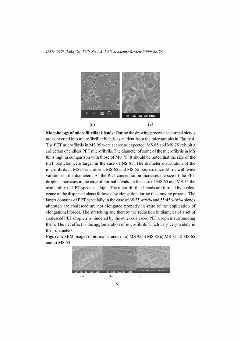
Morphology of microfibrillar blends: During the drawing process the normal blendsare converted into microfibrillar blends as evident from the micrographs in Figure 4.The PET microfibrils in MS 95 were scarce as expected. MS 85 and MS 75 exhibit acollection of endless PET microfibrils. The diameter of some of the microfibrils in MS85 is high in comparison with those of MS 75. It should be noted that the size of thePET particles were larger in the case of NS 85. The diameter distribution of themicrofibrils in MS75 is uniform. MS 65 and MS 55 possess microfibrils with widevariation in the diameters. As the PET concentration increases the size of the PETdroplets increases in the case of normal blends. In the case of MS 65 and MS 55 theavailability of PET species is high. The microfibrillar blends are formed by coales-cence of the dispersed phase followed by elongation during the drawing process. Thelarger domains of PET especially in the case of 65/35 w/w% and 55/45 w/w% blendsalthough are coalesced are not elongated properly in spite of the application ofelongational forces. The stretching and thereby the reduction in diameter of a set ofcoalesced PET droplets is hindered by the other coalesced PET droplets surroundingthem. The net effect is the agglomeration of microfibrils which vary very widely intheir diameters.Figure 4: SEM images of normal strands of a) MS 95 b) MS 85 c) MS 75 d) MS 65and e) MS 55
ISSN: 0973-7464 Vol. XVI: No.1 & 2 SB Academic Review 2009: 66-76
77
(d) (e)
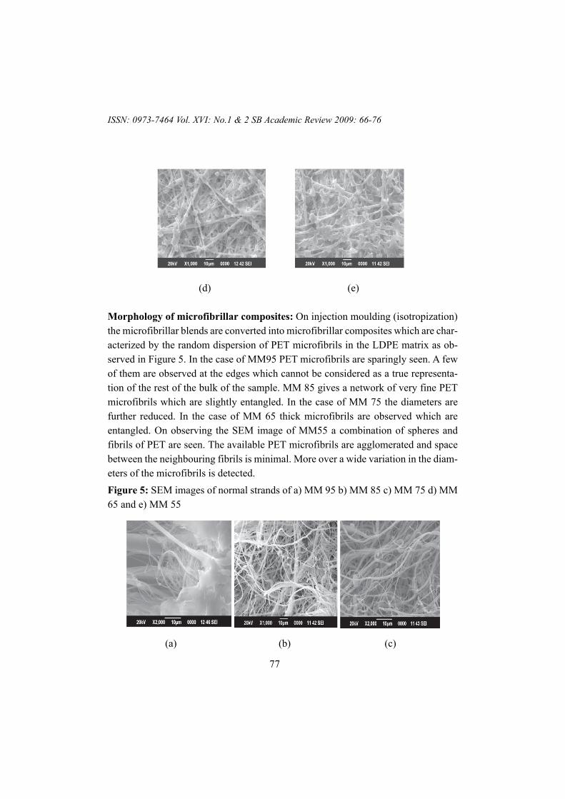
Morphology of microfibrillar composites: On injection moulding (isotropization)the microfibrillar blends are converted into microfibrillar composites which are char-acterized by the random dispersion of PET microfibrils in the LDPE matrix as ob-served in Figure 5. In the case of MM95 PET microfibrils are sparingly seen. A fewof them are observed at the edges which cannot be considered as a true representa-tion of the rest of the bulk of the sample. MM 85 gives a network of very fine PETmicrofibrils which are slightly entangled. In the case of MM 75 the diameters arefurther reduced. In the case of MM 65 thick microfibrils are observed which areentangled. On observing the SEM image of MM55 a combination of spheres andfibrils of PET are seen. The available PET microfibrils are agglomerated and spacebetween the neighbouring fibrils is minimal. More over a wide variation in the diam-eters of the microfibrils is detected.Figure 5: SEM images of normal strands of a) MM 95 b) MM 85 c) MM 75 d) MM65 and e) MM 55
(a) (b) (c)
ISSN: 0973-7464 Vol. XVI: No.1 & 2 SB Academic Review 2009: 66-76
78
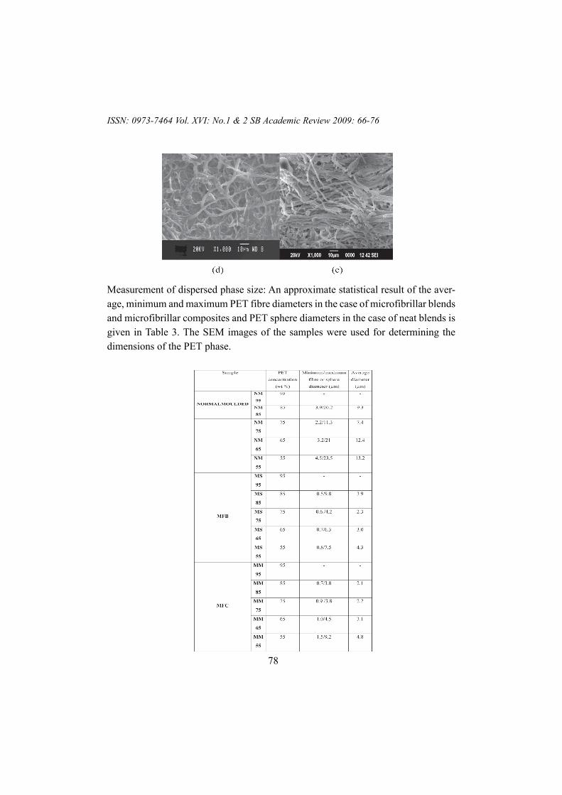
Measurement of dispersed phase size: An approximate statistical result of the aver-age, minimum and maximum PET fibre diameters in the case of microfibrillar blendsand microfibrillar composites and PET sphere diameters in the case of neat blends isgiven in Table 3. The SEM images of the samples were used for determining thedimensions of the PET phase.
57 page
ISSN: 0973-7464 Vol. XVI: No.1 & 2 SB Academic Review 2009: 66-76
79
Table 3 Average, maximum and minimum diameters of PET spheres/fibresSome trends can be observed from the analysis of the size of the PET spheres
and fibrils. The minimum diameter of the PET domains in the case of microfibrillarblends are not affected much by the PET concentration. The average diameter of thePET domains is found to increase with PET concentration in the case of normalblends. In the case of microfibrillar blends the diameter of the PET microfibrils showsan increasing trend from 25 to 45 % of PET concentration. The difference betweenthe diameters of the fibrils is highest in MS 85 amongst the microfibrillar blends andMM55 in the case of microfibrillar composites.
CONCLUSION
The morphology of the normal blends and the corresponding MFCs based onLDPE and PET are analysed at the various stages of their preparation. The dispersedphase exhibits a spherical/nodular morphology in the case of the normal blends. Thedispersed phase remains as discrete domains pointing towards the immiscibility of thephases. The average diameter of PET phase increases with an increase in the PETconcentration for the normal blends. The morphology of the blends exhibits co conti-nuity at very high PET concentration of 45 wt%. The fibrillation of the dispersedphase is scantily seen at its low concentration in the case of MFBs. At 15 and 25 wt%of PET loading completely formed microfibrils of PET is observed. At 25 wt% PETconcentration, PET microfibrils of uniform diameter distribution is detected. At higherPET concentrations the fibrils formed are not uniform in their diameters. Duringisotropization for the preparation of MFCs the aspect ratio of the PET microfibrilsreduced due to the "break up behaviour". A network of PET microfibrils was seen at15 and 25 wt% PET concentration. The diameter of the microfibrils was the lowestfor M85 and M75.At 35 wt% PET concentration the microfibrils are found to beagglomerated. At 45 wt% PET loading a combination spherical and fibrillar domainsof the dispersed phase is seen in the MFCs. The fibrillar domains are found to beaggregated obviously due to its increased availability.
REFERENCE
Dlaby I, Ernst B, Froelich D, Miller R (1996). Droplet deformation in immiscible polymer blendsduring transient uniaxial elongational flow. Polym Eng Sci 36:1627-1635
Dreal VE, Vinogradov GV, Plotnikova EP, Zabagina MP, Plotnikova NP, Kotova EV, Pelzbauer Z(1983). Deformation of melts of mixtures of incompatible polymers in a uniform shear field andthe process of their fibrillation. Rheol Acta 22:102-107
Fakirov S (1990). Solid state behaviour in linear polyesters and polyamides. Prentice Hall,New Jersey
ISSN: 0973-7464 Vol. XVI: No.1 & 2 SB Academic Review2009: 66-76
80
Fakirov S, Evstatiev M (1994). Microfibrillar reinforced composites - new materials from poly-mer blends. Adv Mater. 6:395-398
Favis BD (1999). In Shonaik GO, Simon GP (eds) Polymer Blends and Alloys. Marcel Dekker,New York
Flory PJ (1953). Principles of polymer chemistry. Cornell University Press, Ithaca
Fuchs C, Bhattacharyya D, Fakirov S (2006). Microfibril reinforced polymer-polymer compos-ites: Application of Tsai-Hill equation to PP/PET composites. Compos Sci Technol, 66:3161-3171
Fuchs C, Bhattacharyya D, Friedrich K, Fakirov S (2006). Application of Halpin-Tsai equationto microfibril reinforced polypropylene/poly (ethylene terephthalate) compos
ites. Compos Interf, 13: 331- 344
Grace MP (1982). Dispersion phenomena in high viscosity immiscible fluid systems and appli-cation of static mixers as dispersion devices in such systems. Chem Eng Commun, 14: 225-277
Leung KL, Easteal A, Bhattacharyya D (2008). In situ formation of poly (ethylene naphthalate)microfibrils in polyethylene and polypropylene during extrusion.Compos Part A ,39: 662-676
Li ZM, Yang MB, Feng JM, Yang W, Huang R (2002). Morphology of in situ poly(ethyleneterephthalate)/polyethylene microfiber reinforced composite formed via slit-die extrusion andhot-stretching. Mater Res Bull, 37: 2185-2197
Li ZM, Yang MB, Lu A, Feng JM, Huang R, Feng JM (2003). In-situ microfiber reinforcedcomposite based on PET and PE via slit die extrusion and hot stretching: Influences of hotstretching ratio on morphology and tensile properties at a fixed composition. Polym Eng Sci,43: 615-628
Lin XD, Cheung WL (2003). Study of poly(ethylene terephthalate)/polypropylene microfibril-lar composites. I. Morphological development in melt extrusion. J Appl Polym Sci, 89: 1743-1752
Migler KB (2001). String formation in sheared polymer blends: coalescence, breakup, and finitesize effects. Phys Rev Lett, 86: 1023-1026
Yang MB, Li ZM, Feng JM (1998). Studies on high density polyethylene/polycarbonate blendsystem compatibilized with low density polyethylene grafted diallyl bisphenol A ether. PolymEng Sci, 38: 879-883
ISSN: 0973-7464 Vol. XVI: No.1 & 2 SB Academic Review 2009: 66-76