Embed Size (px)
Citation preview
Micromechanics of Particle-ModifiedSemicrystalline Polymers
Influence of Anisotropy due to Transcrystallinity and/or Flow
J. A. W. van Dommelen and H. E. H. Meijer
Dutch Polymer Institute, Eindhoven University of Technology,Department of Mechanical Engineering,
PO Box 513, 5600 MB Eindhoven, The Netherlands
1 Introduction
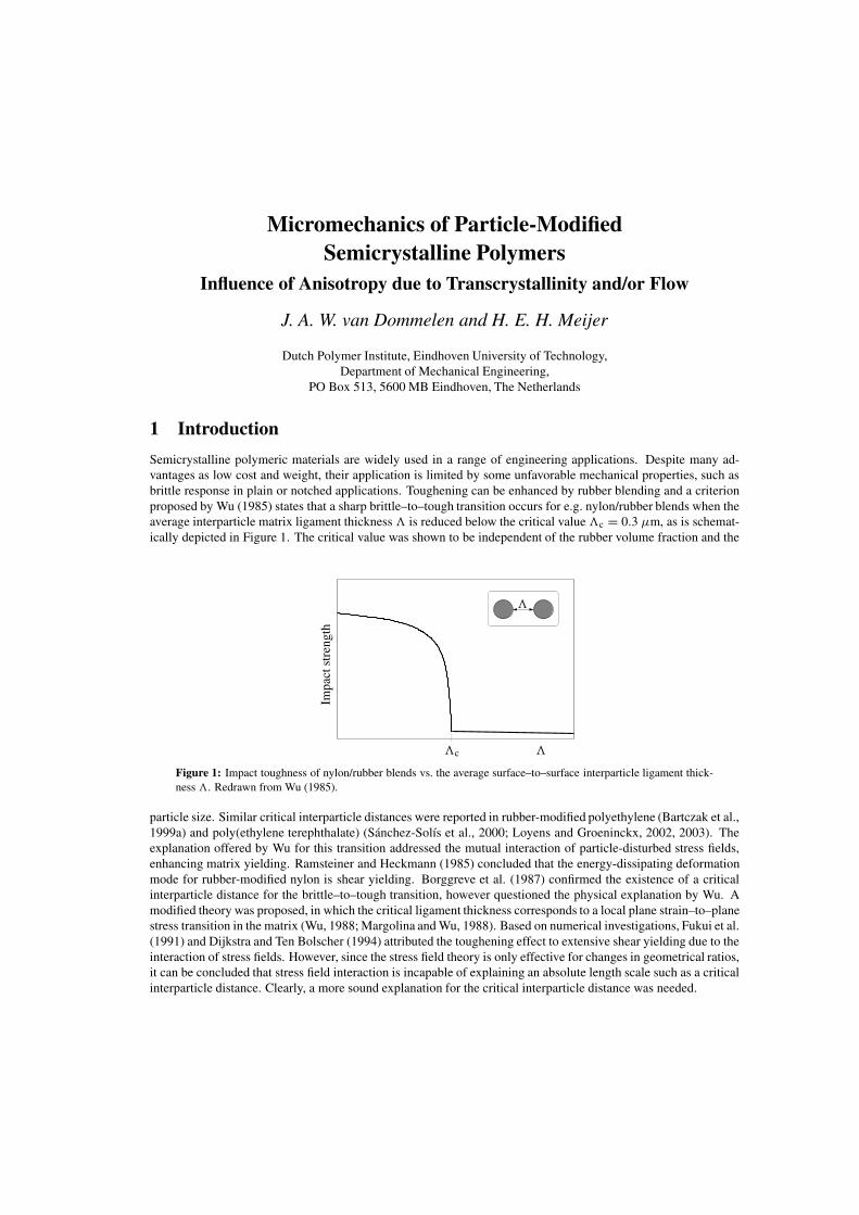
Semicrystalline polymeric materials are widely used in a range of engineering applications. Despite many ad-vantages as low cost and weight, their application is limited by some unfavorable mechanical properties, such asbrittle response in plain or notched applications. Toughening can be enhanced by rubber blending and a criterionproposed by Wu (1985) states that a sharp brittle–to–tough transition occurs for e.g. nylon/rubber blends when theaverage interparticle matrix ligament thickness � is reduced below the critical value �c = 0.3 µm, as is schemat-ically depicted in Figure 1. The critical value was shown to be independent of the rubber volume fraction and the
Impa
ctst
reng
th
�
�
�c
Figure 1: Impact toughness of nylon/rubber blends vs. the average surface–to–surface interparticle ligament thick-ness �. Redrawn from Wu (1985).
particle size. Similar critical interparticle distances were reported in rubber-modified polyethylene (Bartczak et al.,1999a) and poly(ethylene terephthalate) (Sanchez-Solıs et al., 2000; Loyens and Groeninckx, 2002, 2003). Theexplanation offered by Wu for this transition addressed the mutual interaction of particle-disturbed stress fields,enhancing matrix yielding. Ramsteiner and Heckmann (1985) concluded that the energy-dissipating deformationmode for rubber-modified nylon is shear yielding. Borggreve et al. (1987) confirmed the existence of a criticalinterparticle distance for the brittle–to–tough transition, however questioned the physical explanation by Wu. Amodified theory was proposed, in which the critical ligament thickness corresponds to a local plane strain–to–planestress transition in the matrix (Wu, 1988; Margolina and Wu, 1988). Based on numerical investigations, Fukui et al.(1991) and Dijkstra and Ten Bolscher (1994) attributed the toughening effect to extensive shear yielding due to theinteraction of stress fields. However, since the stress field theory is only effective for changes in geometrical ratios,it can be concluded that stress field interaction is incapable of explaining an absolute length scale such as a criticalinterparticle distance. Clearly, a more sound explanation for the critical interparticle distance was needed.
Micromechanics of Particle-Modified Semicrystalline Polymers J. A. W. van Dommelen and H. E. H. Meijer
1.1 Toughening mechanism
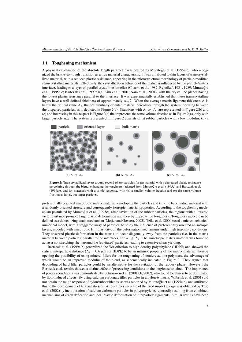
A physical explanation of the absolute length parameter was offered by Muratoglu et al. (1995a,c), who recog-nized the brittle–to–tough transition as a true material characteristic. It was attributed to thin layers of transcrystal-lized material, with a reduced plastic resistance, appearing in the microstructural morphology of particle-modifiedsemicrystalline materials. Effectively, the crystallization behavior of the matrix is influenced by the particle/matrixinterface, leading to a layer of parallel crystalline lamellae (Chacko et al., 1982; Rybnikar, 1981, 1989; Muratogluet al., 1995a,c; Bartczak et al., 1999a,b,c; Kim et al., 2001; Nam et al., 2001), with the crystalline planes havingthe lowest plastic resistance parallel to the interface. It was experimentally established that these transcrystallinelayers have a well-defined thickness of approximately �c/2. When the average matrix ligament thickness � isbelow the critical value �c, the preferentially oriented material percolates through the system, bridging betweenthe dispersed particles, as is depicted in Figure 2(a). Situations with � � �c are represented in Figure 2(b) and(c) and interesting in this respect is Figure 2(c) that represents the same volume fraction as in Figure 2(a), only withlarger particle size. The system represented in Figure 2 consists of (i) rubber particles with a low modulus, (ii) a
particle oriented layer bulk matrix
(a) � ≤ �c (b) � � �c (c) � � �c
Figure 2: Transcrystallized layers around second-phase particles for (a) material with a decreased plastic resistancepercolating through the blend, enhancing the toughness (adopted from Muratoglu et al. (1995c) and Bartczak et al.(1999a)), and for materials with a brittle response, with (b) a smaller volume fraction and (c) the same volumefraction as in (a), but larger particles.
preferentially oriented anisotropic matrix material, enveloping the particles and (iii) the bulk matrix material witha randomly oriented structure and consequently isotropic material properties. According to the toughening mech-anism postulated by Muratoglu et al. (1995c), after cavitation of the rubber particles, the regions with a loweredyield resistance promote large plastic deformation and thereby improve the toughness. Toughness indeed can bedefined as a delocalizing strain mechanism (Meijer and Govaert, 2003). Tzika et al. (2000) used a micromechanicalnumerical model, with a staggered array of particles, to study the influence of preferentially oriented anisotropiclayers, modeled with anisotropic Hill plasticity, on the deformation mechanisms under high triaxiality conditions.They observed plastic deformation in the matrix to occur diagonally away from the particles (i.e. in the matrixmaterial between particles, parallel to the interfaces) for � ≤ �c. The anisotropic matrix material was found toact as a nonstretching shell around the (cavitated) particles, leading to extensive shear yielding.
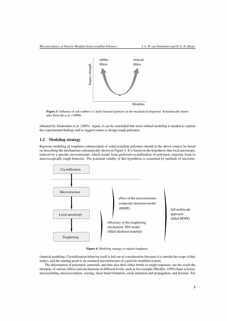
Bartczak et al. (1999a,b) generalized the Wu criterion to high density polyethylene (HDPE) and showed thecritical interparticle distance (�c = 0.6 µm for HDPE) to be an intrinsic property of the matrix material, therebyopening the possibility of using mineral fillers for the toughening of semicrystalline polymers, the advantage ofwhich would be an improved modulus of the blend, as schematically indicated in Figure 3. They argued thatdebonding of hard filler particles could be an alternative for the cavitation of the rubbery phase. However, theBartczak et al. results showed a distinct effect of processing conditions on the toughness obtained. The importanceof process conditions was demonstrated by Schrauwen et al. (2001a,b, 2002), who found toughness to be dominatedby flow-induced effects. By using calcium carbonate filler particles in a nylon-6 matrix, Wilbrink et al. (2001) didnot obtain the tough response of nylon/rubber blends, as was reported by Muratoglu et al. (1995c,b), and attributedthis to the development of triaxial stresses. A four times increase of the Izod impact energy was obtained by Thioet al. (2002) by incorporation of calcium carbonate particles in polypropylene, reportedly resulting from combinedmechanisms of crack deflection and local plastic deformation of interparticle ligaments. Similar results have been
2
Micromechanics of Particle-Modified Semicrystalline Polymers J. A. W. van Dommelen and H. E. H. Meijer
Modulus
Impa
ctst
reng
th fillersfillersrubber mineral
Figure 3: Influence of soft (rubber) vs. hard (mineral) particles on the mechanical properties. Schematically drawnafter Bartczak et al. (1999b).
obtained by Zuiderduin et al. (2003). Again, it can be concluded that more refined modeling is needed to explainthe experimental findings and to suggest routes to design tough polymers.
1.2 Modeling strategy
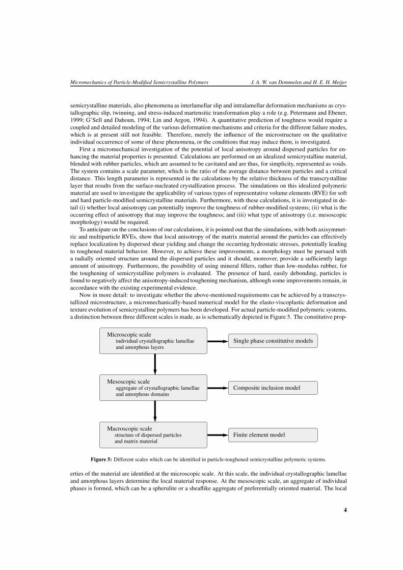
Rigorous modeling of toughness enhancement of semicrystalline polymers should in the above context be basedon describing the mechanisms schematically shown in Figure 4. It is based on the hypothesis that local anisotropy,induced by a specific microstructure, which results from preferred crystallization of polymeric material, leads tomacroscopically tough behavior. The potential validity of this hypothesis is examined by methods of microme-
Crystallization
Microstructure
Local anisotropy
Toughening
composite inclusion model
effect of the microstructure:
(HDPE)
efficiency of the tougheningmechanism: Hill model(filled idealized material)
full multiscaleapproach(filled HDPE)
Figure 4: Modeling strategy to explain toughness.
chanical modeling. Crystallization behavior itself is left out of consideration (because it is outside the scope of thisstudy), and the starting-point is an assumed microstructure of a particle-modified system.
The deformation of polymeric materials, and thus also their either brittle or tough responses, are the result theinterplay of various effects and mechanisms at different levels, such as for example (Michler, 1999) chain scission,microyielding, microcavitation, crazing, shear band formation, crack initiation and propagation, and fracture. For
3
Micromechanics of Particle-Modified Semicrystalline Polymers J. A. W. van Dommelen and H. E. H. Meijer
semicrystalline materials, also phenomena as interlamellar slip and intralamellar deformation mechanisms as crys-tallographic slip, twinning, and stress-induced martensitic transformation play a role (e.g. Petermann and Ebener,1999; G’Sell and Dahoun, 1994; Lin and Argon, 1994). A quantitative prediction of toughness would require acoupled and detailed modeling of the various deformation mechanisms and criteria for the different failure modes,which is at present still not feasible. Therefore, merely the influence of the microstructure on the qualitativeindividual occurrence of some of these phenomena, or the conditions that may induce them, is investigated.
First a micromechanical investigation of the potential of local anisotropy around dispersed particles for en-hancing the material properties is presented. Calculations are performed on an idealized semicrystalline material,blended with rubber particles, which are assumed to be cavitated and are thus, for simplicity, represented as voids.The system contains a scale parameter, which is the ratio of the average distance between particles and a criticaldistance. This length parameter is represented in the calculations by the relative thickness of the transcrystallinelayer that results from the surface-nucleated crystallization process. The simulations on this idealized polymericmaterial are used to investigate the applicability of various types of representative volume elements (RVE) for softand hard particle-modified semicrystalline materials. Furthermore, with these calculations, it is investigated in de-tail (i) whether local anisotropy can potentially improve the toughness of rubber-modified systems; (ii) what is theoccurring effect of anisotropy that may improve the toughness; and (iii) what type of anisotropy (i.e. mesoscopicmorphology) would be required.
To anticipate on the conclusions of our calculations, it is pointed out that the simulations, with both axisymmet-ric and multiparticle RVEs, show that local anisotropy of the matrix material around the particles can effectivelyreplace localization by dispersed shear yielding and change the occurring hydrostatic stresses, potentially leadingto toughened material behavior. However, to achieve these improvements, a morphology must be pursued witha radially oriented structure around the dispersed particles and it should, moreover, provide a sufficiently largeamount of anisotropy. Furthermore, the possibility of using mineral fillers, rather than low-modulus rubber, forthe toughening of semicrystalline polymers is evaluated. The presence of hard, easily debonding, particles isfound to negatively affect the anisotropy-induced toughening mechanism, although some improvements remain, inaccordance with the existing experimental evidence.
Now in more detail: to investigate whether the above-mentioned requirements can be achieved by a transcrys-tallized microstructure, a micromechanically-based numerical model for the elasto-viscoplastic deformation andtexture evolution of semicrystalline polymers has been developed. For actual particle-modified polymeric systems,a distinction between three different scales is made, as is schematically depicted in Figure 5. The constitutive prop-
Microscopic scaleindividual crystallographic lamellaeand amorphous layers
and amorphous domains
Mesoscopic scaleaggregate of crystallographic lamellae
Macroscopic scalestructure of dispersed particlesand matrix material
Single phase constitutive models
Composite inclusion model
Finite element model
Figure 5: Different scales which can be identified in particle-toughened semicrystalline polymeric systems.
erties of the material are identified at the microscopic scale. At this scale, the individual crystallographic lamellaeand amorphous layers determine the local material response. At the mesoscopic scale, an aggregate of individualphases is formed, which can be a spherulite or a sheaflike aggregate of preferentially oriented material. The local
4
Micromechanics of Particle-Modified Semicrystalline Polymers J. A. W. van Dommelen and H. E. H. Meijer
inclusion-averaged deformation and stress fields are related to the mesoscopic fields by a polycrystalline aggre-gate model. The effect of a transcrystallized structure of matrix material versus randomly oriented material onboth mesoscopic and microscopic results is examined. A limited effect of the preferential orientations is observed.Further improved properties are obtained for a partly flow-induced microstructure, if loaded in the appropriatedirection.
2 Soft fillers: can local anisotropy induce toughness? 1
The potential of plastic anisotropy for enhancing the toughness of semicrystalline polymeric materials is inves-tigated. Calculations are performed on idealized semicrystalline materials, blended with rubber particles, whichare assumed to be cavitated and are represented by spherical voids. The system contains a length scale parameter,which is the ratio of the average distance between voids and a critical distance, and is represented by the absolutethickness of the transcrystalline anisotropic layer around the voids. We will start the analysis using a simple Hillanisotropic plasticity constitutive model, that is, subsequently, applied to a micromechanical RVE.
2.1 Constitutive model of the anisotropic bulk polymer
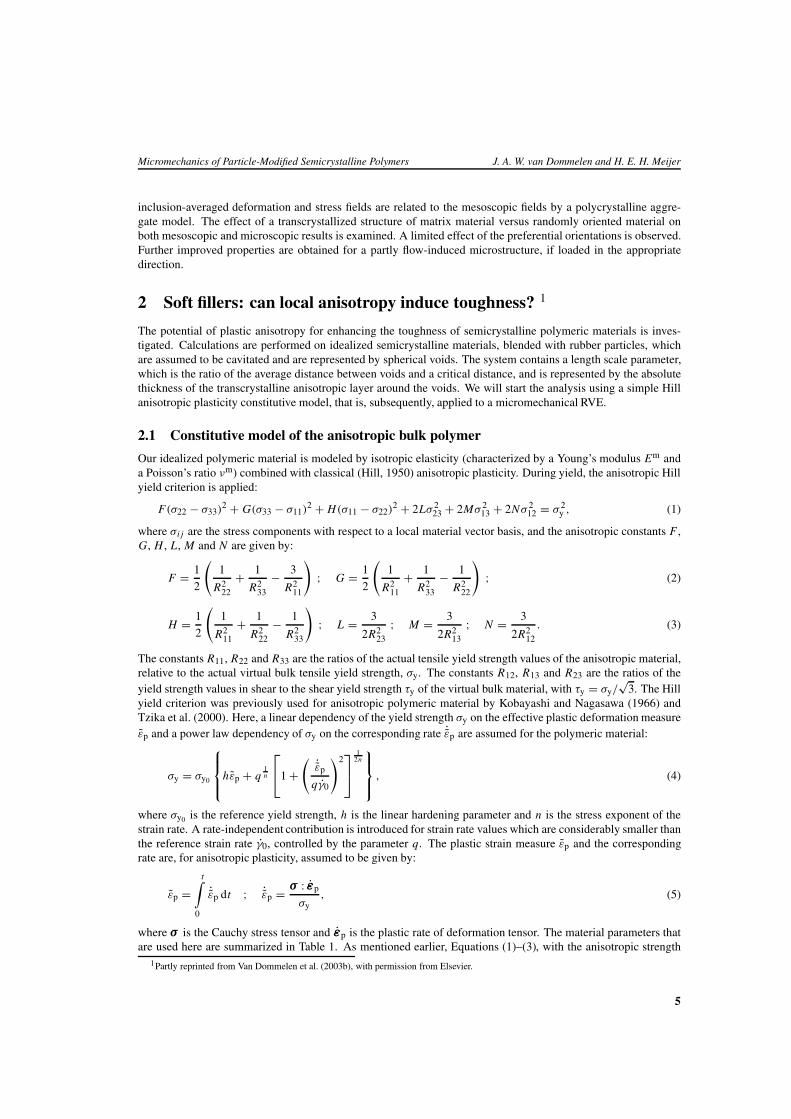
Our idealized polymeric material is modeled by isotropic elasticity (characterized by a Young’s modulus Em anda Poisson’s ratio νm) combined with classical (Hill, 1950) anisotropic plasticity. During yield, the anisotropic Hillyield criterion is applied:
F(σ22 − σ33)2 + G(σ33 − σ11)
2 + H(σ11 − σ22)2 + 2Lσ 2
23 + 2Mσ 213 + 2Nσ 2
12 = σ 2y , (1)
where σi j are the stress components with respect to a local material vector basis, and the anisotropic constants F ,G, H , L, M and N are given by:
F = 1
2
(1
R222
+ 1
R233
− 3
R211
); G = 1
2
(1
R211
+ 1
R233
− 1
R222
); (2)
H = 1
2
(1
R211
+ 1
R222
− 1
R233
); L = 3
2R223
; M = 3
2R213
; N = 3
2R212
. (3)
The constants R11, R22 and R33 are the ratios of the actual tensile yield strength values of the anisotropic material,relative to the actual virtual bulk tensile yield strength, σy. The constants R12, R13 and R23 are the ratios of theyield strength values in shear to the shear yield strength τy of the virtual bulk material, with τy = σy/
√3. The Hill
yield criterion was previously used for anisotropic polymeric material by Kobayashi and Nagasawa (1966) andTzika et al. (2000). Here, a linear dependency of the yield strength σy on the effective plastic deformation measureεp and a power law dependency of σy on the corresponding rate ˙εp are assumed for the polymeric material:
σy = σy0
hεp + q
1n
1 +
( ˙εp
qγ0
)2
12n
, (4)
where σy0 is the reference yield strength, h is the linear hardening parameter and n is the stress exponent of thestrain rate. A rate-independent contribution is introduced for strain rate values which are considerably smaller thanthe reference strain rate γ0, controlled by the parameter q. The plastic strain measure εp and the correspondingrate are, for anisotropic plasticity, assumed to be given by:
εp =t∫
0
˙εp dt ; ˙εp = σ : εp
σy, (5)
where σ is the Cauchy stress tensor and εp is the plastic rate of deformation tensor. The material parameters thatare used here are summarized in Table 1. As mentioned earlier, Equations (1)–(3), with the anisotropic strength
1Partly reprinted from Van Dommelen et al. (2003b), with permission from Elsevier.
5
Micromechanics of Particle-Modified Semicrystalline Polymers J. A. W. van Dommelen and H. E. H. Meijer
Em [GPa] νm σy0 [MPa] h γ0 [s−1] n q R11 R22 R33 R12 R13 R23
1 0.45 25 0.6 10−3 9 10−2 1 1 1 1/ζ 1/ζ 1
Table 1: Material parameters for a fictitious polymer matrix.
ratios Ri j , are applied in a local coordinate system. The transcrystallized material around the voids is assumed tohave a reduced plastic resistance with respect to the local 12 and 13 shear components (at the void/matrix interface,the 1-direction is defined to be perpendicular to the interface), and the reduction is controlled by only one adjustableparameter ζ .
2.2 Micromechanical models
The heterogeneous particle-filled system is described by a finite element model of a representative volume elementthat generally and intrinsically have a three-dimensional structure. Full three-dimensional numerical analyses,however, are computationally extremely demanding and, therefore, first two different simplified models are used.
For an adequate representation of the triaxial stress state around a void, an axisymmetric RVE is used, assuggested by Socrate and Boyce (2000) and Tzika et al. (2000). However, because of the regular void stackingassociated to such RVEs, important effects as sequential yielding of the matrix material between the differentvoids (Smit et al., 1999) cannot be accounted for. In order to capture the essentially irregular nature of a systemof dispersed voids, also a plane strain RVE is used, which is incapable of capturing the triaxial stress-effects.A comparison of the simplified two-dimensional models with three-dimensional calculations is presented in VanDommelen et al. (2003b).
2.2.1 The first model: an axisymmetric RVE, the SA model
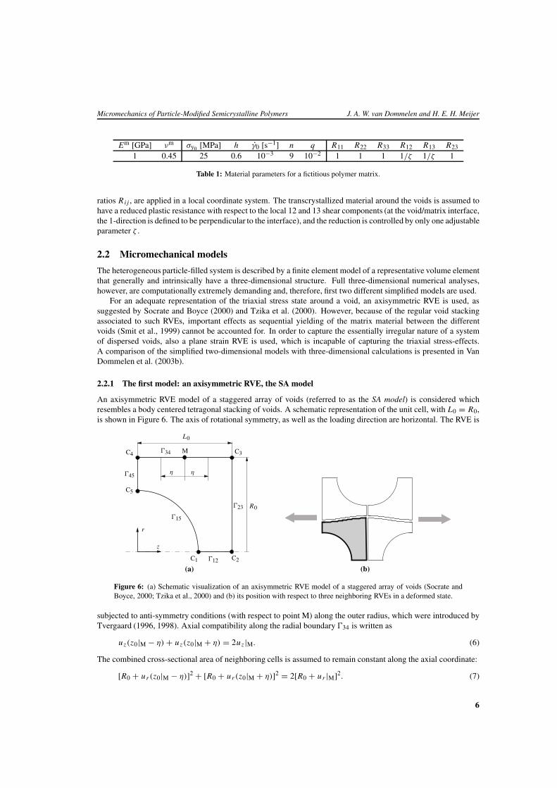
An axisymmetric RVE model of a staggered array of voids (referred to as the SA model) is considered whichresembles a body centered tetragonal stacking of voids. A schematic representation of the unit cell, with L0 = R0,is shown in Figure 6. The axis of rotational symmetry, as well as the loading direction are horizontal. The RVE is
C1 C2
C3C4
C5
M
�12
�23
�34
�45
�15
R0
L0
η η
r
z
(a) (b)
Figure 6: (a) Schematic visualization of an axisymmetric RVE model of a staggered array of voids (Socrate andBoyce, 2000; Tzika et al., 2000) and (b) its position with respect to three neighboring RVEs in a deformed state.
subjected to anti-symmetry conditions (with respect to point M) along the outer radius, which were introduced byTvergaard (1996, 1998). Axial compatibility along the radial boundary �34 is written as
uz(z0|M − η) + uz(z0|M + η) = 2uz |M. (6)
The combined cross-sectional area of neighboring cells is assumed to remain constant along the axial coordinate:
[R0 + ur (z0|M − η)]2 + [R0 + ur (z0|M + η)]2 = 2[R0 + ur |M]2. (7)
6
Micromechanics of Particle-Modified Semicrystalline Polymers J. A. W. van Dommelen and H. E. H. Meijer
Symmetry conditions along the right and left boundaries are written as
uz |�23 = uz |C2 (8)
and
uz |�45 = uz |C5, (9)
respectively. Since the axis of rotational symmetry coincides with boundary �12, the following condition is im-posed on this boundary:
ur |�12 = 0. (10)
The axisymmetric RVE is subjected to tension at a macroscopically constant strain rate:
uz |C2 − uz |C5 = L0[exp(ε t) − 1], (11)
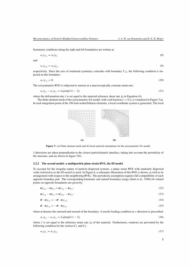
where the deformation rate ε is set equal to the material reference shear rate γ0 in Equation (4).The finite element mesh of the axisymmetric SA model, with void fraction f = 0.2, is visualized in Figure 7(a).
In each integration point of the 196 four-noded bilinear elements, a local coordinate system is generated. The local
(a) (b)
Figure 7: (a) Finite element mesh and (b) local material orientations for the axisymmetric SA model.
1-directions are taken perpendicular to the closest particle/matrix interface, taking into account the periodicity ofthe structure, and are shown in figure 7(b).
2.2.2 The second model: a multiparticle plane strain RVE, the ID model
To account for the irregular nature of particle-dispersed systems, a plane strain RVE with randomly dispersedvoids (referred to as the ID model) is used. In Figure 8, a schematic illustration of this RVE is shown, as well as itsarrangement with respect to the neighboring RVEs. The periodicity assumption requires full compatibility of eachopposite boundary pair. The corresponding kinematic and natural boundary tyings (Smit et al., 1998) for relatedpoints on opposite boundaries are given by:
u|�34 − u|C4 = u|�12 − u|C1; (12)
u|�14 − u|C1 = u|�23 − u|C2; (13)
σ · n|�12 = −σ · n|�34; (14)
σ · n|�14 = −σ · n|�23, (15)
where n denotes the outward unit normal of the boundary. A tensile loading condition in x-direction is prescribed:
ux |C2 − ux |C1 = L0[exp(εt) − 1], (16)
where ε is set equal to the reference strain rate γ0 of the material. Furthermore, rotations are prevented by thefollowing condition for the vertices C1 and C2:
uy |C1 = uy |C2 . (17)
7
Micromechanics of Particle-Modified Semicrystalline Polymers J. A. W. van Dommelen and H. E. H. Meijer
x
y
L0
L0
C1 C2
C3C4
�12
�23
�34
�14
(a) (b)
Figure 8: (a) Schematic visualization of a multiparticle plane strain RVE (Smit et al., 1998) and (b) its position withrespect to neighboring RVEs in a deformed state.
The relative displacements of C4 are unspecified and follow from the analysis, whereas the displacements of C3are tied to the other vertices.
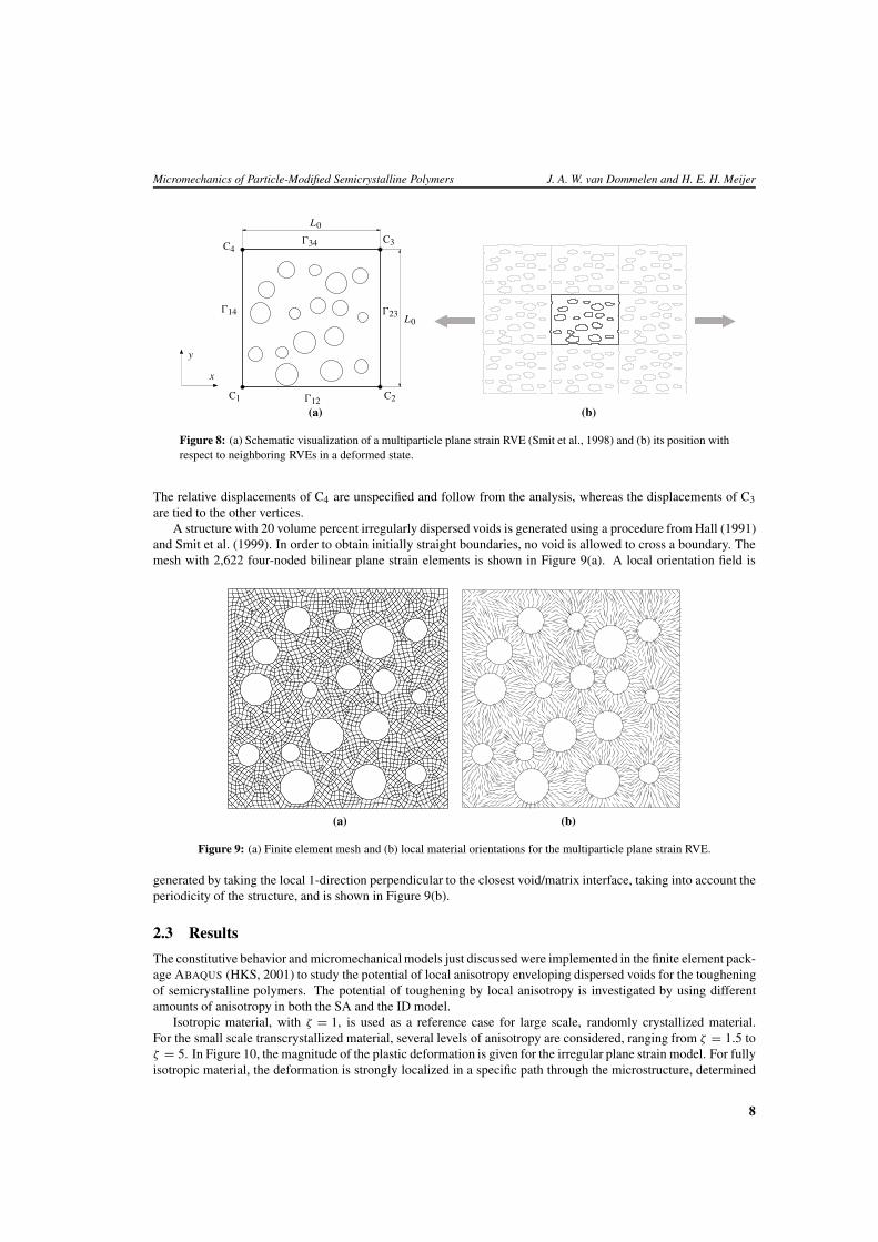
A structure with 20 volume percent irregularly dispersed voids is generated using a procedure from Hall (1991)and Smit et al. (1999). In order to obtain initially straight boundaries, no void is allowed to cross a boundary. Themesh with 2,622 four-noded bilinear plane strain elements is shown in Figure 9(a). A local orientation field is
(a) (b)
Figure 9: (a) Finite element mesh and (b) local material orientations for the multiparticle plane strain RVE.
generated by taking the local 1-direction perpendicular to the closest void/matrix interface, taking into account theperiodicity of the structure, and is shown in Figure 9(b).
2.3 Results
The constitutive behavior and micromechanical models just discussed were implemented in the finite element pack-age ABAQUS (HKS, 2001) to study the potential of local anisotropy enveloping dispersed voids for the tougheningof semicrystalline polymers. The potential of toughening by local anisotropy is investigated by using differentamounts of anisotropy in both the SA and the ID model.
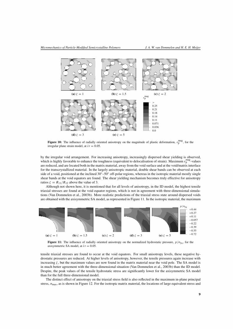
Isotropic material, with ζ = 1, is used as a reference case for large scale, randomly crystallized material.For the small scale transcrystallized material, several levels of anisotropy are considered, ranging from ζ = 1.5 toζ = 5. In Figure 10, the magnitude of the plastic deformation is given for the irregular plane strain model. For fullyisotropic material, the deformation is strongly localized in a specific path through the microstructure, determined
8
Micromechanics of Particle-Modified Semicrystalline Polymers J. A. W. van Dommelen and H. E. H. Meijer
(a) ζ = 1 (b) ζ = 1.5 (c) ζ = 2ε
magp
0.00.0360.0710.110.140.180.210.25>
(d) ζ = 3 (e) ζ = 5
Figure 10: The influence of radially oriented anisotropy on the magnitude of plastic deformation, εmagp , for the
irregular plane strain model, at εt = 0.05.
by the irregular void arrangement. For increasing anisotropy, increasingly dispersed shear yielding is observed,which is highly favorable to enhance the toughness (equivalent to delocalisation of strain). Maximum ε
magp -values
are reduced, and are located both in the matrix material, away from the void surface and at the void/matrix interfacefor the transcrystallized material. In the largely anisotropic material, double shear bands can be observed at eachside of a void, positioned at the inclined 30◦–50◦ off-polar regions, whereas in the isotropic material mostly singleshear bands at the void equators are found. The shear yielding mechanism becomes truly effective for anisotropyratios ζ = R11/R12 above the value of 3.
Although not shown here, it is mentioned that for all levels of anisotropy, in the ID model, the highest tensiletriaxial stresses are found at the void equator regions, which is not in agreement with three-dimensional simula-tions (Van Dommelen et al., 2003b). More realistic predictions of the triaxial stress state around dispersed voidsare obtained with the axisymmetric SA model, as represented in Figure 11. In the isotropic material, the maximum
p/σy0
−0.72−0.55−0.39−0.22−0.057+0.11+0.27+0.44
(a) ζ = 1 (b) ζ = 1.5 (c) ζ = 2 (d) ζ = 3 (e) ζ = 5
Figure 11: The influence of radially oriented anisotropy on the normalized hydrostatic pressure, p/σy0 , for theaxisymmetric SA model, at ε t = 0.05.
tensile triaxial stresses are found to occur at the void equators. For small anisotropy levels, these negative hy-drostatic pressures are reduced. At higher levels of anisotropy, however, the tensile pressures again increase withincreasing ζ , but the maximum values are now found in the matrix material near the void pole. The SA model isin much better agreement with the three-dimensional situation (Van Dommelen et al., 2003b) than the ID model.Despite, the peak values of the tensile hydrostatic stress are significantly lower for the axisymmetric SA modelthan for the full three-dimensional model.
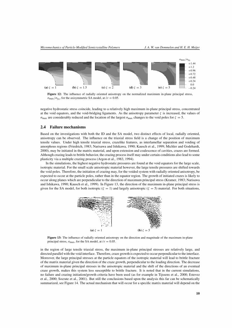
The distinct effect of anisotropy on the triaxial stress field is also reflected in the maximum in-plane principalstress, σmax, as is shown in Figure 12. For the isotropic matrix material, the locations of large equivalent stress and
9
Micromechanics of Particle-Modified Semicrystalline Polymers J. A. W. van Dommelen and H. E. H. Meijer
σmax/σy0
−0.240.0
+0.24+0.48+0.72+0.96+1.2+1.44
(a) ζ = 1 (b) ζ = 1.5 (c) ζ = 2 (d) ζ = 3 (e) ζ = 5
Figure 12: The influence of radially oriented anisotropy on the normalized maximum in-plane principal stress,σmax/σy0 , for the axisymmetric SA model, at εt = 0.05.
negative hydrostatic stress coincide, leading to a relatively high maximum in-plane principal stress, concentratedat the void equators, and the void-bridging ligaments. As the anisotropy parameter ζ is increased, the values ofσmax are considerably reduced and the location of the largest σmax changes to the void poles for ζ = 5.
2.4 Failure mechanisms
Based on the investigations with both the ID and the SA model, two distinct effects of local, radially oriented,anisotropy can be observed. The influence on the triaxial stress field is a change of the position of maximumtensile values. Under high tensile triaxial stress, crazelike features, as interlamellar separation and voiding ofamorphous regions (Friedrich, 1983; Narisawa and Ishikawa, 1990; Kausch et al., 1999; Michler and Godehardt,2000), may be initiated in the matrix material, and upon extension and coalescence of cavities, crazes are formed.Although crazing leads to brittle behavior, the crazing process itself may under certain conditions also lead to someplasticity via a multiple crazing process (Argon et al., 1983, 1994).
In the simulations, the highest negative hydrostatic pressures are found at the void equators for the large scale,isotropic material. For the small scale anisotropic material however, the large tensile pressures are shifted towardsthe void poles. Therefore, the initiation of crazing may, for the voided system with radially oriented anisotropy, beexpected to occur at the particle poles, rather than in the equator region. The growth of initiated crazes is likely tooccur along planes which are perpendicular to the direction of maximum principal stress (Kramer, 1983; Narisawaand Ishikawa, 1990; Kausch et al., 1999). In Figure 13, the direction of the maximum in-plane principal stress isgiven for the SA model, for both isotropic (ζ = 1) and largely anisotropic (ζ = 5) material. For both situations,
(a) ζ = 1 (b) ζ = 5
Figure 13: The influence of radially oriented anisotropy on the direction and magnitude of the maximum in-planeprincipal stress, σmax, for the SA model, at εt = 0.05.
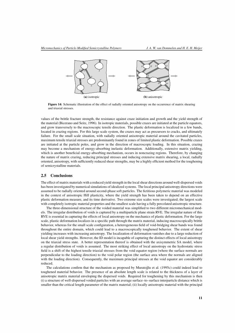
in the region of large tensile triaxial stress, the maximum in-plane principal stresses are relatively large, anddirected parallel with the void interface. Therefore, craze growth is expected to occur perpendicular to the interface.Moreover, the large principal stresses at the particle equators of the isotropic material will lead to brittle fractureof the matrix material given the direction of the craze growth, perpendicular to the loading direction. The decreaseof maximum in-plane principal stresses in the anisotropic material and the shift of the directions of an eventualcraze growth, makes this system less susceptible to brittle fracture. It is noted that in the current simulations,no failure and crazing initiation/growth criteria have been used (as for example in Tijssens et al., 2000; Estevezet al., 2000; Socrate et al., 2001). But still the conclusions based upon the analysis this far can be schematicallysummarized, see Figure 14. The actual mechanism that will occur for a specific matrix material will depend on the
10
Micromechanics of Particle-Modified Semicrystalline Polymers J. A. W. van Dommelen and H. E. H. Meijer
(a) isotropic (b) anisotropic
Figure 14: Schematic illustration of the effect of radially oriented anisotropy on the occurrence of matrix shearingand triaxial stresses.
values of the brittle fracture strength, the resistance against craze initiation and growth and the yield strength ofthe material (Bicerano and Seitz, 1996). In isotropic materials, possible crazes are initiated at the particle equators,and grow transversely to the macroscopic tensile direction. The plastic deformation is localized in a few bands,located in crazing regions. For this large scale system, the crazes may act as precursors to cracks, and ultimatelyfailure. For the small scale situation, with radially oriented anisotropic material around the cavitated particles,maximum tensile triaxial stresses are predominantly found in zones of limited plastic deformation. Possible crazesare initiated at the particle poles, and grow in the direction of macroscopic loading. In this situation, crazingmay become a mechanism of energy-absorbing inelastic deformation. Additionally, extensive matrix yielding,which is another beneficial energy-absorbing mechanism, occurs in noncrazing regions. Therefore, by changingthe nature of matrix crazing, reducing principal stresses and inducing extensive matrix shearing, a local, radiallyoriented, anisotropy, with sufficiently reduced shear strengths, may be a highly efficient method for the tougheningof semicrystalline materials.
2.5 Conclusions
The effect of matrix materials with a reduced yield strength in the local shear directions around well-dispersed voidshas been investigated by numerical simulations of idealized systems. The local principal anisotropy directions wereassumed to be radially oriented around second-phase soft particles. The fictitious polymeric material was modeledin the context of anisotropic Hill plasticity, where the yield strength has been taken to depend on an effectiveplastic deformation measure, and its time derivative. Two extreme size scales were investigated; the largest scalewith completely isotropic material properties and the smallest scale having a fully percolated anisotropic structure.
The three-dimensional structure of the voided material was simplified to two different micromechanical mod-els. The irregular distribution of voids is captured by a multiparticle plane strain RVE. The irregular nature of thisRVE is essential in capturing the effects of local anisotropy on the mechanics of plastic deformation. For the largescale, plastic deformation localizes in a specific path through the matrix material, inducing macroscopically brittlebehavior, whereas for the small scale configuration, a heterogeneous field of void-bridging shear bands was foundthroughout the entire domain, which could lead to a macroscopically toughened behavior. The extent of shearyielding increases with increasing anisotropy. The localization of deformation vanishes due to a large reduction oflocal shear yield strengths. However, the ID model is incapable of capturing the distinct effects of local anisotropyon the triaxial stress state. A better representation thereof is obtained with the axisymmetric SA model, wherea regular distribution of voids is assumed. The most striking effect of local anisotropy on the hydrostatic stressfield is a shift of the highest tensile triaxial stresses from the void equator region (where the surface normals areperpendicular to the loading direction) to the void polar region (the surface area where the normals are alignedwith the loading direction). Consequently, the maximum principal stresses at the void equator are considerablyreduced.
The calculations confirm that the mechanism as proposed by Muratoglu et al. (1995c) could indeed lead totoughened material behavior. The presence of an absolute length scale is related to the thickness of a layer ofanisotropic matrix material enveloping the dispersed voids. Required for toughening by this mechanism is then(i) a structure of well-dispersed voided particles with an average surface–to–surface interparticle distance which issmaller than the critical length parameter of the matrix material; (ii) locally anisotropic material with the principal
11
Micromechanics of Particle-Modified Semicrystalline Polymers J. A. W. van Dommelen and H. E. H. Meijer
1-direction radially oriented with respect to the nearest void surface; and (iii) a sufficiently reduced shear yieldstrength in the local 12- and 13-directions (with ζ = R11/R12 at least of the order of 3).
It is noted that although the large potential of local anisotropy for toughening of semicrystalline polymers wasshown, the origin of this anisotropy has not been addressed here. The material was merely assumed to be orientedwith the principal 1-direction of anisotropy towards the nearest void and having a finite anisotropic layer thickness.The origin of these layers is attributed to a preferred crystallization at the particle/matrix interface by Muratogluet al. (1995c) and Bartczak et al. (1999a,b). The consequences of such a morphology for local anisotropy will beaddressed in Section 4.
3 Hard particles: can they also act as toughness modifiers? 2
A physically-based mechanism for the toughening of semicrystalline polymeric materials due to the dispersion ofparticles originates from the presence of a layer of anisotropic transcrystallized material enveloping the particles,and was proposed for nylon by Muratoglu et al. (1995c). Bartczak et al. (1999a,b) generalized this mechanismto other semicrystalline materials (like high density polyethylene) and showed the critical interparticle distance tobe an intrinsic property of the matrix material, thereby opening the possibility of using mineral fillers instead ofrubber particles for the toughening of semicrystalline polymers, the advantage of which would be an improvedmodulus of the blend. They argued that debonding of hard filler particles could be an alternative for the cavitationof the rubbery phase.
In Section 2, an idealized, polymeric matrix material was modeled by anisotropic Hill plasticity, and variousrepresentative volume elements were used to describe the system containing dispersed voids. It was shown thata local plastic anisotropy of matrix material around the voids can effectively replace localization by dispersedshear yielding and change the occurring hydrostatic stresses, potentially leading to toughened material behavior.However, to achieve these improvements, a morphology should be pursued that has a radially oriented structurearound the dispersed voids and provides a sufficiently large amount of anisotropy.
In this section, the consequence of using hard mineral particles for the toughening of semicrystalline polymersis investigated. For this purpose, again the anisotropic Hill model is used. The system contains a scale parameter,which is the ratio of the average distance between particles and a critical distance. The value of this parameteris represented in the calculations by the relative thickness of an anisotropic layer around the particles. Large andsmall scale configurations are modeled again by entirely isotropic or anisotropic matrix material, respectively.
3.1 Model description
The influence of mineral (i.e. hard) filler particles in semicrystalline polymeric material is investigated, and par-ticularly the effect of these fillers on the mechanism of toughening by locally induced anisotropy. As a referencesituation, voided matrix material will be used. A distinction is made between fully bonded particles, for which atied particle/matrix interface is used, and debonding particles. For the latter, a contact algorithm (HKS, 2001) witha relatively low maximum tensile strength σ i/σy0 = 0.4 is used to describe the particle/matrix interaction. Theeffect of relatively stiff rubber particles is presented in Van Dommelen et al. (2003e).
For the yield behavior, again the anisotropic Hill yield criterion (Hill, 1950) is used, with a rate-dependentand hardening yield stress, as discussed in Section 2. The mineral filler particles are modeled as linearly elastic,with Young’s modulus Ep = 80 GPa and Poisson’s ratio νp = 0.3. Particle-modified material is again describedby a finite element model of a representative volume element (RVE). The particle-modified system, having athree-dimensional nature, is simplified to a two-dimensional RVE, for which two different approaches are used, asdiscussed in Section 2.
3.2 Results
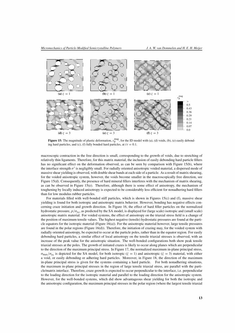
In Figure 15, the magnitudes of plastic deformation as obtained by the ID model are shown for systems containingboth debonded and fully bonded hard filler particles, for both isotropic (ζ = 1, i.e. large scale) and anisotropic(ζ = 3, i.e. small scale) matrix material, respectively. For the voided isotropic matrix material (Figure 15(a)), the
2Partly reprinted from Van Dommelen et al. (2003e), with permission from Elsevier.
12
Micromechanics of Particle-Modified Semicrystalline Polymers J. A. W. van Dommelen and H. E. H. Meijer
(a) ζ = 1 (b) ζ = 1 (c) ζ = 1ε
magp
0.00.070.140.210.290.360.430.5>
(d) ζ = 3 (e) ζ = 3 (f) ζ = 3
Figure 15: The magnitude of plastic deformation, εmagp , for the ID model with (a), (d) voids, (b), (e) easily debond-
ing hard particles, and (c), (f) fully bonded hard particles, at ε t = 0.1.
macroscopic contraction in the free direction is small, corresponding to the growth of voids, due to stretching ofrelatively thin ligaments. Therefore, for this matrix material, the inclusion of easily debonding hard particle fillershas no significant effect on the deformation observed, as can be seen by comparison with Figure 15(b), wherethe interface strength σ i is negligibly small. For radially oriented anisotropic voided material, a dispersed mode ofmassive shear yielding is observed, with double shear bands at each side of a particle. As a result of matrix shearing,for the voided anisotropic system, however, the voids become smaller in the macroscopically free direction, seeFigure 15(d). Consequently, the presence of hard mineral fillers interferes with the mechanism of matrix shearing,as can be observed in Figure 15(e). Therefore, although there is some effect of anisotropy, the mechanism oftoughening by locally induced anisotropy is expected to be considerably less efficient for nonadhering hard fillersthan for low modulus rubber particles.
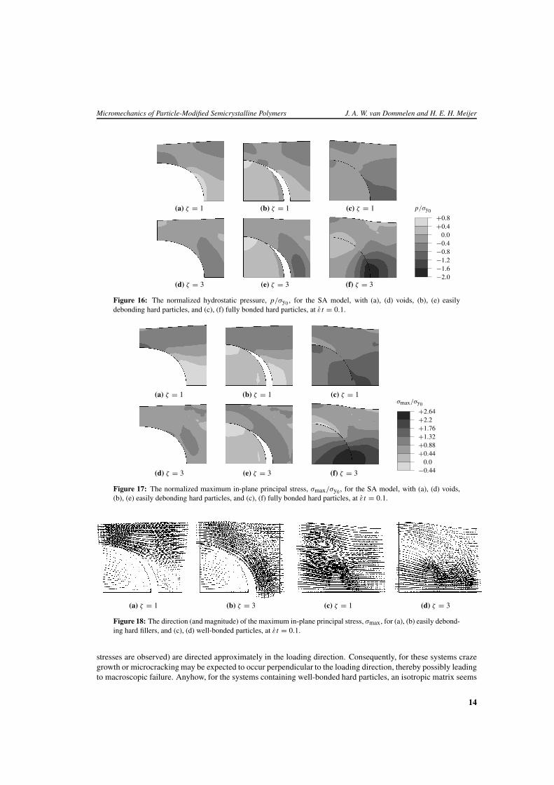
For materials filled with well-bonded stiff particles, which is shown in Figures 15(c) and (f), massive shearyielding is found for both isotropic and anisotropic matrix behavior. However, bonding has negative effects con-cerning craze initiation and growth direction. In Figure 16, the effect of hard filler particles on the normalizedhydrostatic pressure, p/σy0 , as predicted by the SA model, is displayed for (large scale) isotropic and (small scale)anisotropic matrix material. For voided systems, the effect of anisotropy on the triaxial stress field is a change ofthe position of maximum tensile values. The highest negative (tensile) hydrostatic pressures are found at the parti-cle equators for the isotropic material (Figure 16(a)). For the anisotropic material however, large tensile pressuresare found in the polar regions (Figure 16(d)). Therefore, the initiation of crazing may, for the voided system withradially oriented anisotropy, be expected to occur at the particle poles, rather than in the equator region. For easilydebonding hard particles, a similar effect of local anisotropy on the tensile triaxial stresses is observed, with anincrease of the peak value for the anisotropic situation. The well-bonded configurations both show peak tensiletriaxial stresses at the poles. The growth of initiated crazes is likely to occur along planes which are perpendicularto the direction of the maximum principal stress. In Figure 17, the normalized maximum in-plane principal stress,σmax/σy0 is depicted for the SA model, for both isotropic (ζ = 1) and anisotropic (ζ = 3) material, with eithera void, or easily debonding or adhering hard particles. Moreover, in Figure 18, the direction of the maximumin-plane principal stress is given for the systems containing a hard particle. For both nonadhering situations,the maximum in-plane principal stresses in the region of large tensile triaxial stress, are parallel with the parti-cle/matrix interface. Therefore, craze growth is expected to occur perpendicular to the interface, i.e. perpendicularto the loading direction for the isotropic material and parallel to the loading direction for the anisotropic system.However, for the well-bonded systems, which did show advantageous shear yielding for both the isotropic andthe anisotropic configuration, the maximum principal stresses in the polar region (where the largest tensile triaxial
13
Micromechanics of Particle-Modified Semicrystalline Polymers J. A. W. van Dommelen and H. E. H. Meijer
(a) ζ = 1 (b) ζ = 1 (c) ζ = 1 p/σy0
−2.0−1.6−1.2−0.8−0.4
0.0+0.4+0.8
(d) ζ = 3 (e) ζ = 3 (f) ζ = 3
Figure 16: The normalized hydrostatic pressure, p/σy0 , for the SA model, with (a), (d) voids, (b), (e) easilydebonding hard particles, and (c), (f) fully bonded hard particles, at ε t = 0.1.
(a) ζ = 1 (b) ζ = 1 (c) ζ = 1σmax/σy0
−0.440.0
+0.44+0.88+1.32+1.76+2.2+2.64
(d) ζ = 3 (e) ζ = 3 (f) ζ = 3
Figure 17: The normalized maximum in-plane principal stress, σmax/σy0 , for the SA model, with (a), (d) voids,(b), (e) easily debonding hard particles, and (c), (f) fully bonded hard particles, at εt = 0.1.
(a) ζ = 1 (b) ζ = 3 (c) ζ = 1 (d) ζ = 3
Figure 18: The direction (and magnitude) of the maximum in-plane principal stress, σmax, for (a), (b) easily debond-ing hard fillers, and (c), (d) well-bonded particles, at εt = 0.1.
stresses are observed) are directed approximately in the loading direction. Consequently, for these systems crazegrowth or microcracking may be expected to occur perpendicular to the loading direction, thereby possibly leadingto macroscopic failure. Anyhow, for the systems containing well-bonded hard particles, an isotropic matrix seems
14
Micromechanics of Particle-Modified Semicrystalline Polymers J. A. W. van Dommelen and H. E. H. Meijer
to be favorable over locally anisotropic material.
3.3 Conclusions
Fictitious, idealized, polymeric matrix materials were modeled by anisotropic Hill plasticity in Section 2, wherethe distinct effect of local plastic anisotropy of matrix material around the voids was shown, viz. an effective re-placement of localization by dispersed shear yielding and a change of the occurring hydrostatic stresses, potentiallyleading to toughened material behavior. In this section, a similar modeling approach was used to investigate theinfluence of mineral filler particles on this toughening mechanism.
The use of mineral filler particles for toughening of polymeric materials requires debonding in order to preventexcessive tensile hydrostatic stresses. These debonded hard particles show a relocation of tensile triaxial stressesto the particle polar areas by local anisotropy, similarly to anisotropic voided systems, with the maximum principalstresses directed such that crazes or microcracks are expected parallel to the loading direction. However, theanisotropy-induced shear yielding mechanism is affected by the presence of stiff inclusions.
4 Full multiscale modeling: what did we learn? 3
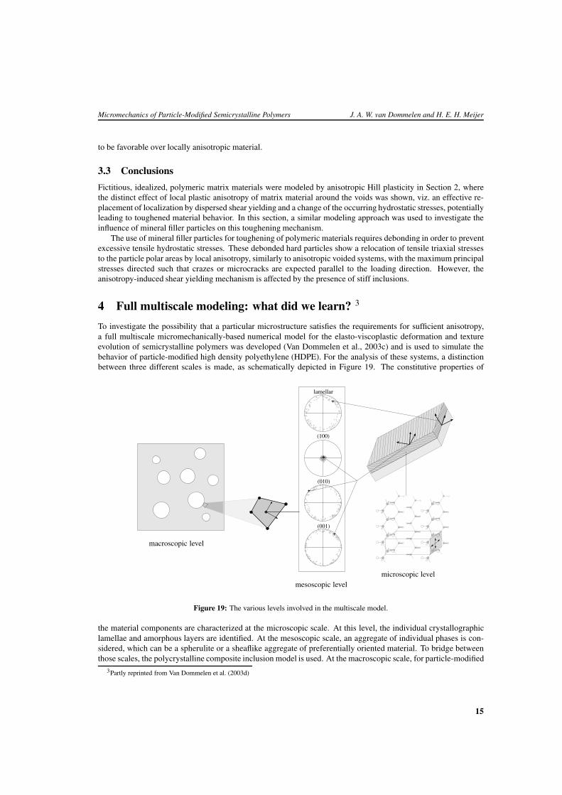
To investigate the possibility that a particular microstructure satisfies the requirements for sufficient anisotropy,a full multiscale micromechanically-based numerical model for the elasto-viscoplastic deformation and textureevolution of semicrystalline polymers was developed (Van Dommelen et al., 2003c) and is used to simulate thebehavior of particle-modified high density polyethylene (HDPE). For the analysis of these systems, a distinctionbetween three different scales is made, as schematically depicted in Figure 19. The constitutive properties of
microscopic levelmesoscopic level
macroscopic level
(100)
(010)
(001)
lamellar
Figure 19: The various levels involved in the multiscale model.
the material components are characterized at the microscopic scale. At this level, the individual crystallographiclamellae and amorphous layers are identified. At the mesoscopic scale, an aggregate of individual phases is con-sidered, which can be a spherulite or a sheaflike aggregate of preferentially oriented material. To bridge betweenthose scales, the polycrystalline composite inclusion model is used. At the macroscopic scale, for particle-modified
3Partly reprinted from Van Dommelen et al. (2003d)
15
Micromechanics of Particle-Modified Semicrystalline Polymers J. A. W. van Dommelen and H. E. H. Meijer
materials, a structure of dispersed particles and matrix material can be identified. At this level, the system is rep-resented by a finite element model using various representative volume elements, as suggested by the Hill-typesimulations of Section 2. A bridge to the mesoscopic level is obtained by using an aggregate of composite inclu-sions as a representative microstructural unit in each integration point. The effect of transcrystallized orientationsof matrix material versus randomly oriented material on both mesoscopic and microscopic results is investigated,as well as a hypothesized microstructure, which may be the result of process conditions.
4.1 Microscopic scale: material models
The anisotropic constitutive behavior of intraspherulitic material is modeled by an aggregate of elasto-viscoplastictwo-phase composite inclusions Lee et al. (1993a,b). Each inclusion consists of a crystalline and an amorphousphase. In this section, the constitutive models of the constituent phases are shortly discussed. For a more elaboratepresentation of these models, see Van Dommelen et al. (2003c).
4.1.1 Crystalline phase
The crystalline domain of polymeric material consists of regularly ordered molecular chains. The crystal structureresults in (i) anisotropic elastic behavior where the elastic properties are given with respect to the crystallographicdirections, and (ii) plastic deformation governed primarily by crystallographic slip on a limited number of slipplanes (G’Sell and Dahoun, 1994; Argon, 1997). Moreover, plastic deformation may result from mechanicaltwinning or stress-induced martensitic phase transformations (Lin and Argon, 1994; G’Sell and Dahoun, 1994;Frank et al., 1970; Young and Bowden, 1974). Since crystallographic slip is assumed to be of most importance forpolymeric materials, in the modeling process the latter two mechanisms are left out of consideration.
The elastic component of the deformation in the crystalline phase is characterized by an anisotropic fourth-order elastic modulus tensor. The anisotropic elastic properties are coupled to the crystallographic directions.For the viscoplastic behavior of the crystalline phase, a rate-dependent crystal plasticity model is used. In thismodel, the plastic velocity gradient of the crystalline lamella, consisting of a single crystal, is composed of thecontributions of all physically distinct slip systems, being 8 for high density polyethylene (HDPE), with a lowestslip resistance of 8 MPa. The shear rate of each slip system is assumed to be related to the resolved shear stressaccording to a viscoplastic power law.
4.1.2 Amorphous phase
The amorphous phase of semicrystalline polymeric material consists of an assembly of disordered macromolecules,which are morphologically constrained by the neighboring crystalline lamellae. Plastic deformation in these do-mains occurs by a thermally activated rotation of segments. At room temperature, the amorphous phase of HDPE,which is the material of interest in this work, is in the rubbery regime, with the glass transition temperaturenear −70 ◦C. The deformation in this regime is characterized by a limited strain rate-sensitivity and a strongentropic hardening at large deformations.
The initial elastic resistance of the rubbery amorphous phase is well below the elastic resistance of the crys-talline domain. Consequently, elastic deformations can be considerably large and are modeled by a generalizedneo-Hookean relationship. A relatively strain rate-insensitive viscoplastic power law relation between an effectiveshear strain rate and the effective shear stress (Lee et al., 1993a) is used in conjunction with a back stress tensorfor which the Arruda–Boyce eight-chain network model of rubber elasticity (Arruda and Boyce, 1993) is used.
4.2 Mesoscopic scale: composite inclusion model
The mechanical behavior at the mesoscopic level is modeled by an aggregate of layered two-phase compositeinclusions as was first proposed by Lee et al. (1993a,b) for rigid/viscoplastic material behavior. Each separatecomposite consists of a crystalline lamella which is mechanically coupled to its corresponding amorphous layer,as is shown in the upper right part of Figure 19. The stress and deformation fields within each phase are assumedto be piecewise homogeneous; however, they may differ between the two coupled phases. It is assumed thatthe crystalline and amorphous components remain fully mechanically coupled. Interface compatibility within thecomposite inclusion and traction equilibrium, across the interface, are enforced. To relate the volume-averaged
16
Micromechanics of Particle-Modified Semicrystalline Polymers J. A. W. van Dommelen and H. E. H. Meijer
mechanical behavior of each composite inclusion to the imposed boundary conditions for an aggregate of inclu-sions, a hybrid local–global interaction law is used. This class of hybrid-inclusion models was introduced by Leeet al. (1993a,b) for rigid/viscoplastic composite inclusions. A more detailed description of the composite inclusionmodel is presented elsewhere (Van Dommelen et al., 2003c). Moreover, an application of this model to study theintraspherulitic deformation of polyethylene is presented in Van Dommelen et al. (2003a). Some aspects of thefinite element implementation in HKS (2001) are given in Van Dommelen et al. (2001).
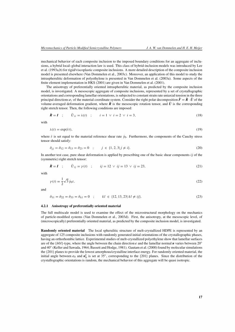
The anisotropy of preferentially oriented intraspherulitic material, as predicted by the composite inclusionmodel, is investigated. A mesoscopic aggregate of composite inclusions, represented by a set of crystallographicorientations and corresponding lamellar orientations, is subjected to constant strain rate uniaxial tension in the threeprincipal directions ei of the material coordinate system. Consider the right polar decomposition F = R · U of thevolume-averaged deformation gradient, where R is the mesoscopic rotation tensor, and U is the correspondingright stretch tensor. Then, the following conditions are imposed:
R = I ; U i i = λ(t) ; i = 1 ∨ i = 2 ∨ i = 3, (18)
with
λ(t) = exp(εt), (19)
where ε is set equal to the material reference shear rate γ0. Furthermore, the components of the Cauchy stresstensor should satisfy:
σj j = σ12 = σ13 = σ23 = 0 ; j ∈ {1, 2, 3| j �= i}. (20)
In another test case, pure shear deformation is applied by prescribing one of the basic shear components i j of the(symmetric) right stretch tensor:
R = I ; U i j = γ (t) ; i j = 12 ∨ i j = 13 ∨ i j = 23, (21)
with
γ (t) = 1
2
√3 γ0 t, (22)
and
σ11 = σ22 = σ33 = σk l = 0 ; k l ∈ {12, 13, 23| k l �= i j}. (23)
4.2.1 Anisotropy of preferentially oriented material
The full multiscale model is used to examine the effect of the microstructural morphology on the mechanicsof particle-modified systems (Van Dommelen et al., 2003d). First, the anisotropy, at the mesoscopic level, of(microscopically) preferentially oriented material, as predicted by the composite inclusion model, is investigated.
Randomly oriented material The local spherulitic structure of melt-crystallized HDPE is represented by anaggregate of 125 composite inclusions with randomly generated initial orientations of the crystallographic phases,having an orthorhombic lattice. Experimental studies of melt-crystallized polyethylene show that lamellar surfacesare of the {h0l}-type, where the angle between the chain direction c and the lamellar normal n varies between 20◦and 40◦ (Keller and Sawada, 1964; Bassett and Hodge, 1981). Gautam et al. (2000) found by molecular simulationsthe {201} planes to provide the lowest amorphous/crystalline interface energy. For randomly oriented material, theinitial angle between c0 and nI
0 is set at 35◦, corresponding to the {201} planes. Since the distribution of thecrystallographic orientations is random, the mechanical behavior of this aggregate will be quasi isotropic.
17
Micromechanics of Particle-Modified Semicrystalline Polymers J. A. W. van Dommelen and H. E. H. Meijer
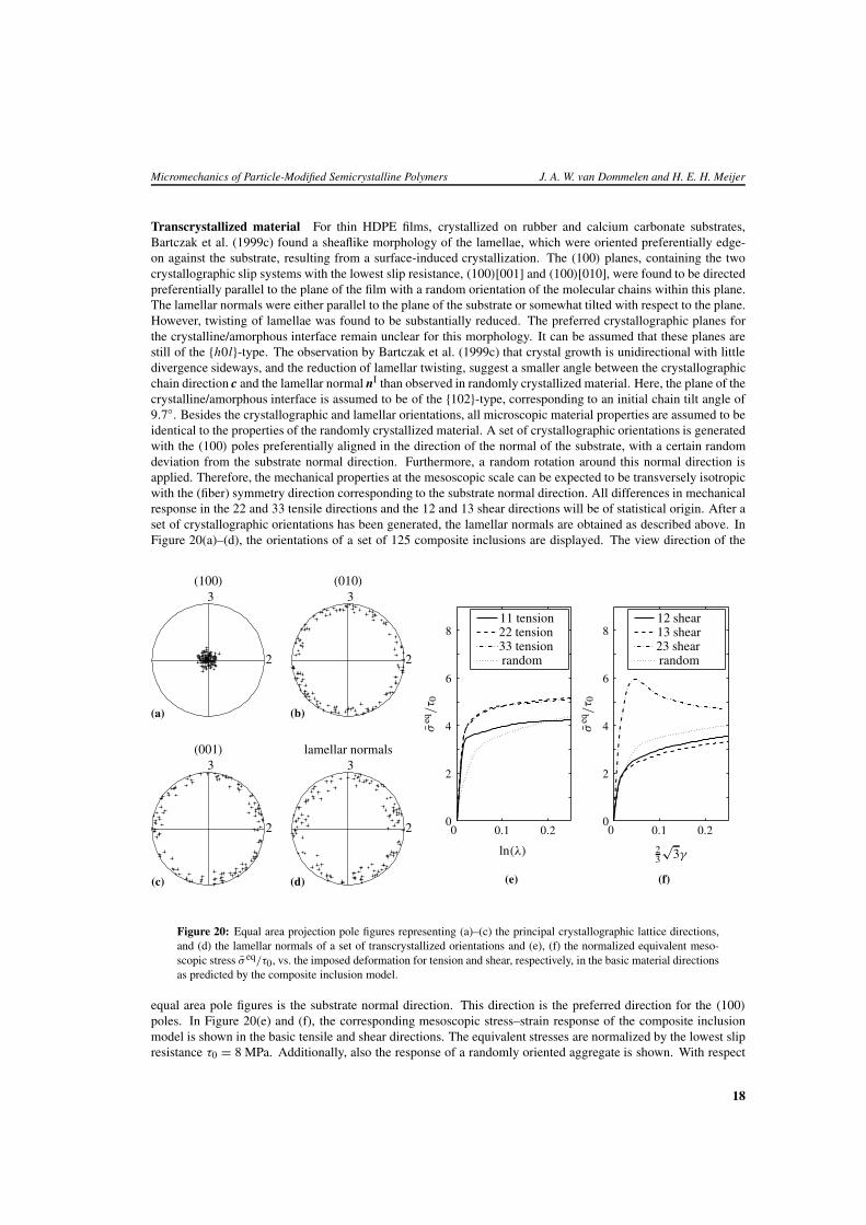
Transcrystallized material For thin HDPE films, crystallized on rubber and calcium carbonate substrates,Bartczak et al. (1999c) found a sheaflike morphology of the lamellae, which were oriented preferentially edge-on against the substrate, resulting from a surface-induced crystallization. The (100) planes, containing the twocrystallographic slip systems with the lowest slip resistance, (100)[001] and (100)[010], were found to be directedpreferentially parallel to the plane of the film with a random orientation of the molecular chains within this plane.The lamellar normals were either parallel to the plane of the substrate or somewhat tilted with respect to the plane.However, twisting of lamellae was found to be substantially reduced. The preferred crystallographic planes forthe crystalline/amorphous interface remain unclear for this morphology. It can be assumed that these planes arestill of the {h0l}-type. The observation by Bartczak et al. (1999c) that crystal growth is unidirectional with littledivergence sideways, and the reduction of lamellar twisting, suggest a smaller angle between the crystallographicchain direction c and the lamellar normal nI than observed in randomly crystallized material. Here, the plane of thecrystalline/amorphous interface is assumed to be of the {102}-type, corresponding to an initial chain tilt angle of9.7◦. Besides the crystallographic and lamellar orientations, all microscopic material properties are assumed to beidentical to the properties of the randomly crystallized material. A set of crystallographic orientations is generatedwith the (100) poles preferentially aligned in the direction of the normal of the substrate, with a certain randomdeviation from the substrate normal direction. Furthermore, a random rotation around this normal direction isapplied. Therefore, the mechanical properties at the mesoscopic scale can be expected to be transversely isotropicwith the (fiber) symmetry direction corresponding to the substrate normal direction. All differences in mechanicalresponse in the 22 and 33 tensile directions and the 12 and 13 shear directions will be of statistical origin. After aset of crystallographic orientations has been generated, the lamellar normals are obtained as described above. InFigure 20(a)–(d), the orientations of a set of 125 composite inclusions are displayed. The view direction of the
(a)
3
2
(100)
3
2
(b)
(010)
3
2
(c)
(001)
3
2
(d)
lamellar normals
ln(λ) 23
√3γ
σeq
/τ 0
σeq
/τ 0
00
00 0.10.1 0.20.2
22
44
66
8811 tension22 tension33 tension
13 shear12 shear
23 shearrandom random
(e) (f)
Figure 20: Equal area projection pole figures representing (a)–(c) the principal crystallographic lattice directions,and (d) the lamellar normals of a set of transcrystallized orientations and (e), (f) the normalized equivalent meso-scopic stress σ eq/τ0, vs. the imposed deformation for tension and shear, respectively, in the basic material directionsas predicted by the composite inclusion model.
equal area pole figures is the substrate normal direction. This direction is the preferred direction for the (100)
poles. In Figure 20(e) and (f), the corresponding mesoscopic stress–strain response of the composite inclusionmodel is shown in the basic tensile and shear directions. The equivalent stresses are normalized by the lowest slipresistance τ0 = 8 MPa. Additionally, also the response of a randomly oriented aggregate is shown. With respect
18
Micromechanics of Particle-Modified Semicrystalline Polymers J. A. W. van Dommelen and H. E. H. Meijer
to the randomly oriented aggregate, the equivalent stresses in the transverse tensile directions are increased. Thereduction of the 12 and 13 shear resistances is related to these tensile 22 and 33 resistances. The ratio of transversetensile and 12/13 shear resistances at the onset of yielding is of the order of 2. At higher strains, this ratio de-creases to approximately 1.5. Simulations with an anisotropic Hill plasticity model (Section 2) showed that for theeffectiveness of the toughening mechanism under investigation, a larger amount of anisotropy would be necessary(ζ ≥ 3). A sharper texture, however, does not increase the R22/R12 anisotropy ratio.
4.3 Macroscopic models
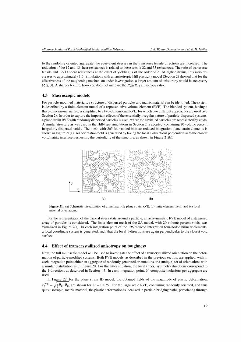
For particle-modified materials, a structure of dispersed particles and matrix material can be identified. The systemis described by a finite element model of a representative volume element (RVE). The blended system, having athree-dimensional nature, is simplified to a two-dimensional RVE, for which two different approaches are used (seeSection 2). In order to capture the important effects of the essentially irregular nature of particle-dispersed systems,a plane strain RVE with randomly dispersed particles is used, where the cavitated particles are represented by voids.A similar structure as was used in the Hill-type simulations in Section 2 is adopted, containing 20 volume percentirregularly dispersed voids. The mesh with 565 four-noded bilinear reduced integration plane strain elements isshown in Figure 21(a). An orientation field is generated by taking the local 1-directions perpendicular to the closestvoid/matrix interface, respecting the periodicity of the structure, as shown in Figure 21(b).
x
y
(a) (b)
Figure 21: (a) Schematic visualization of a multiparticle plane strain RVE, (b) finite element mesh, and (c) localmaterial orientations.
For the representation of the triaxial stress state around a particle, an axisymmetric RVE model of a staggeredarray of particles is considered. The finite element mesh of the SA model, with 20 volume percent voids, wasvisualized in Figure 7(a). In each integration point of the 196 reduced integration four-noded bilinear elements,a local coordinate system is generated, such that the local 1-directions are again perpendicular to the closest voidsurface.
4.4 Effect of transcrystallized anisotropy on toughness
Now, the full multiscale model will be used to investigate the effect of a transcrystallized orientation on the defor-mation of particle-modified systems. Both RVE models, as described in the previous section, are applied, with ineach integration point either an aggregate of randomly generated orientations or a (unique) set of orientations witha similar distribution as in Figure 20. For the latter situation, the local (fiber) symmetry directions correspond tothe 1-directions as described in Section 4.3. In each integration point, 64 composite inclusions per aggregate areused.
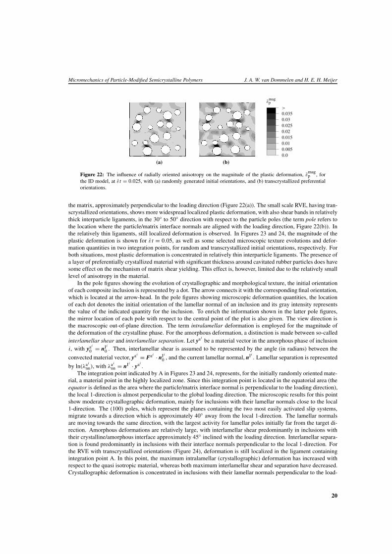
In Figure 22, for the plane strain ID model, the obtained fields of the magnitude of plastic deformation,
εmagp =
√23 εp : εp, are shown for εt = 0.025. For the large scale RVE, containing randomly oriented, and thus
quasi isotropic, matrix material, the plastic deformation is localized in particle-bridging paths, percolating through
19
Micromechanics of Particle-Modified Semicrystalline Polymers J. A. W. van Dommelen and H. E. H. Meijer
εmagp
0.00.0050.010.0150.020.0250.030.035>
(a) (b)
Figure 22: The influence of radially oriented anisotropy on the magnitude of the plastic deformation, εmagp , for
the ID model, at εt = 0.025, with (a) randomly generated initial orientations, and (b) transcrystallized preferentialorientations.
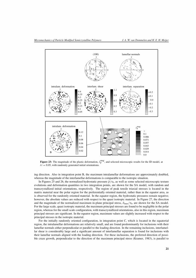
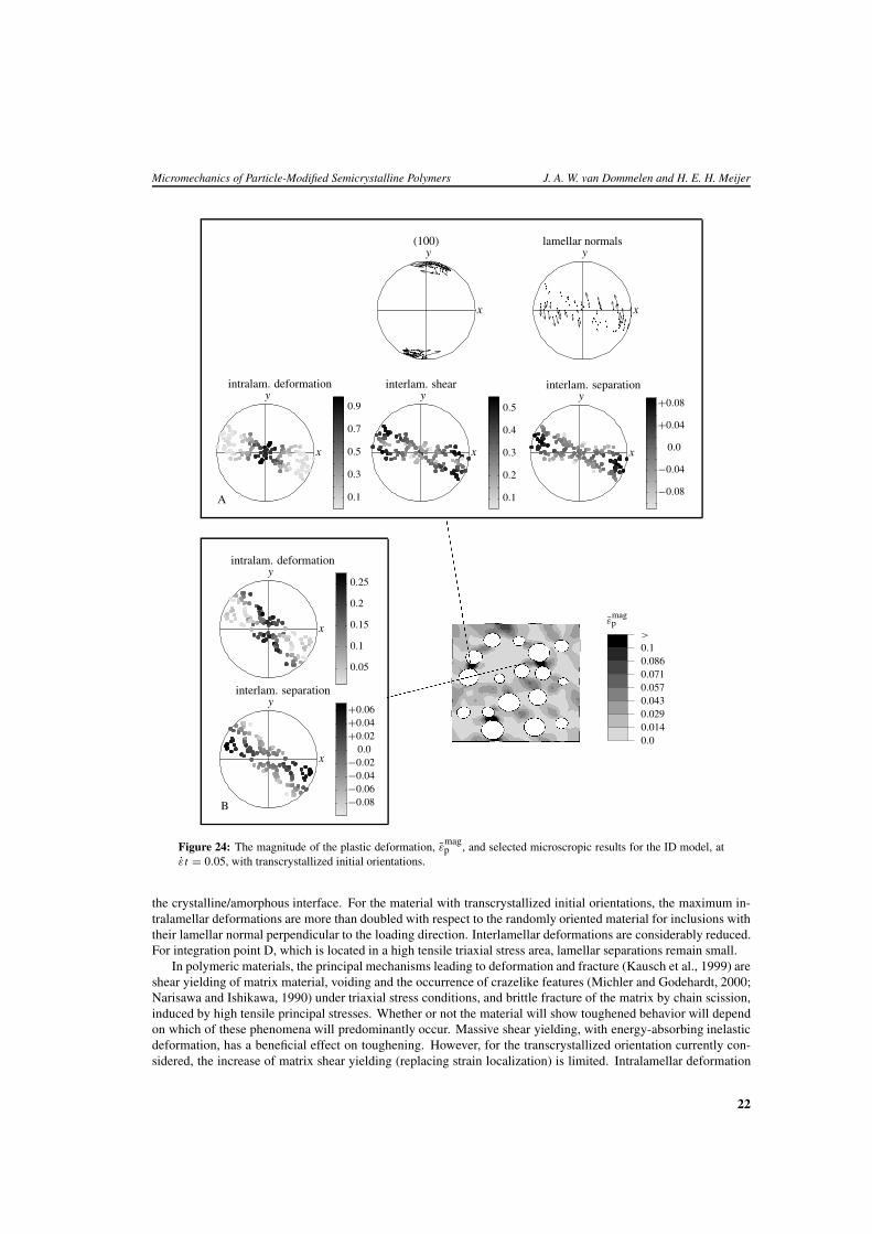
the matrix, approximately perpendicular to the loading direction (Figure 22(a)). The small scale RVE, having tran-scrystallized orientations, shows more widespread localized plastic deformation, with also shear bands in relativelythick interparticle ligaments, in the 30◦ to 50◦ direction with respect to the particle poles (the term pole refers tothe location where the particle/matrix interface normals are aligned with the loading direction, Figure 22(b)). Inthe relatively thin ligaments, still localized deformation is observed. In Figures 23 and 24, the magnitude of theplastic deformation is shown for εt = 0.05, as well as some selected microscopic texture evolutions and defor-mation quantities in two integration points, for random and transcrystallized initial orientations, respectively. Forboth situations, most plastic deformation is concentrated in relatively thin interparticle ligaments. The presence ofa layer of preferentially crystallized material with significant thickness around cavitated rubber particles does havesome effect on the mechanism of matrix shear yielding. This effect is, however, limited due to the relatively smalllevel of anisotropy in the material.
In the pole figures showing the evolution of crystallographic and morphological texture, the initial orientationof each composite inclusion is represented by a dot. The arrow connects it with the corresponding final orientation,which is located at the arrow-head. In the pole figures showing microscopic deformation quantities, the locationof each dot denotes the initial orientation of the lamellar normal of an inclusion and its gray intensity representsthe value of the indicated quantity for the inclusion. To enrich the information shown in the latter pole figures,the mirror location of each pole with respect to the central point of the plot is also given. The view direction isthe macroscopic out-of-plane direction. The term intralamellar deformation is employed for the magnitude ofthe deformation of the crystalline phase. For the amorphous deformation, a distinction is made between so-calledinterlamellar shear and interlamellar separation. Let yai
be a material vector in the amorphous phase of inclusioni, with yai
0 = nIi
0 . Then, interlamellar shear is assumed to be represented by the angle (in radians) between the
convected material vector, yai = Fai · nIi
0 , and the current lamellar normal, nIi. Lamellar separation is represented
by ln(λai
nn), with λai
nn = nIi · yai.
The integration point indicated by A in Figures 23 and 24, represents, for the initially randomly oriented mate-rial, a material point in the highly localized zone. Since this integration point is located in the equatorial area (theequator is defined as the area where the particle/matrix interface normal is perpendicular to the loading direction),the local 1-direction is almost perpendicular to the global loading direction. The microscopic results for this pointshow moderate crystallographic deformation, mainly for inclusions with their lamellar normals close to the local1-direction. The (100) poles, which represent the planes containing the two most easily activated slip systems,migrate towards a direction which is approximately 40◦ away from the local 1-direction. The lamellar normalsare moving towards the same direction, with the largest activity for lamellar poles initially far from the target di-rection. Amorphous deformations are relatively large, with interlamellar shear predominantly in inclusions withtheir crystalline/amorphous interface approximately 45◦ inclined with the loading direction. Interlamellar separa-tion is found predominantly in inclusions with their interface normals perpendicular to the local 1-direction. Forthe RVE with transcrystallized orientations (Figure 24), deformation is still localized in the ligament containingintegration point A. In this point, the maximum intralamellar (crystallographic) deformation has increased withrespect to the quasi isotropic material, whereas both maximum interlamellar shear and separation have decreased.Crystallographic deformation is concentrated in inclusions with their lamellar normals perpendicular to the load-
20
Micromechanics of Particle-Modified Semicrystalline Polymers J. A. W. van Dommelen and H. E. H. Meijer
x
y(100)
x
ylamellar normals
x
y0.4
0.3
0.2
0.1
0.35
0.25
0.15
0.05A
intralam. deformation
x
y
0.3
0.5
0.7
0.9
1.1interlam. shear
x
yinterlam. separation
+0.2
+0.1
0.0
−0.1
−0.2
−0.3
x
y
B
intralam. deformation
0.02
0.04
0.06
0.08
0.1
0.12
CCCCCCCC
�����������
εmagp
0.00.0140.0290.0430.0570.0710.0860.1>
Figure 23: The magnitude of the plastic deformation, εmagp , and selected microscopic results for the ID model, at
εt = 0.05, with randomly generated initial orientations.
ing direction. Also in integration point B, the maximum intralamellar deformations are approximately doubled,whereas the magnitude of the interlamellar deformations is comparable to the isotropic situation.
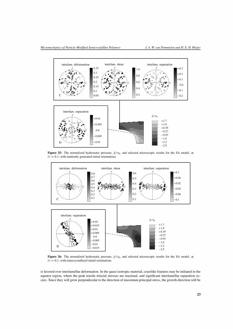
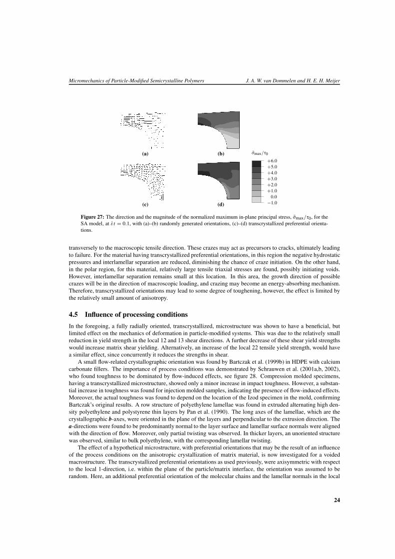
In Figures 25 and 26, the normalized hydrostatic pressure p/τ0, as well as some selected microscopic textureevolutions and deformation quantities in two integration points, are shown for the SA model, with random andtranscrystallized initial orientations, respectively. The region of peak tensile triaxial stresses is located in thematrix material near the polar region for the preferentially oriented material, rather than in the equator area, asis observed for the randomly oriented material. In the equator region, the hydrostatic pressures remain negative;however, the absolute values are reduced with respect to the quasi isotropic material. In Figure 27, the directionand the magnitude of the normalized maximum in-plane principal stress, σmax/τ0, are shown for the SA model.For the large scale, quasi isotropic material, the maximum principal stresses are found to be negligible in the polarregion, whereas for the small scale configuration, with transcrystallized orientations, also in this region, maximumprincipal stresses are significant. In the equator region, maximum values are slightly increased with respect to theprincipal stresses in the isotropic material.
For the initially randomly oriented configuration, in integration point C, which is located in the equatorialregion, the intralamellar deformations are relatively small, and are found predominantly for inclusions with theirlamellar normals either perpendicular or parallel to the loading direction. In the remaining inclusions, interlamel-lar shear is considerably large and a significant amount of interlamellar separation is found for inclusions withtheir lamellar normals aligned with the loading direction. For these inclusions, the preferred direction of possi-ble craze growth, perpendicular to the direction of the maximum principal stress (Kramer, 1983), is parallel to
21
Micromechanics of Particle-Modified Semicrystalline Polymers J. A. W. van Dommelen and H. E. H. Meijer
x
y(100)
x
ylamellar normals
x
y
0.3
0.1
0.5
0.7
0.9
A
intralam. deformation
x
y
0.3
0.1
0.5
interlam. shear
0.2
0.4
x
yinterlam. separation
+0.08
+0.04
0.0
−0.04
−0.08
x
yintralam. deformation
0.05
0.1
0.15
0.2
0.25
x
y
B
+0.06+0.04+0.02
0.0−0.02−0.04−0.06−0.08
interlam. separation
EEEEEEEEEEEE
�����������
εmagp
0.00.0140.0290.0430.0570.0710.0860.1>
Figure 24: The magnitude of the plastic deformation, εmagp , and selected microscropic results for the ID model, at
εt = 0.05, with transcrystallized initial orientations.
the crystalline/amorphous interface. For the material with transcrystallized initial orientations, the maximum in-tralamellar deformations are more than doubled with respect to the randomly oriented material for inclusions withtheir lamellar normal perpendicular to the loading direction. Interlamellar deformations are considerably reduced.For integration point D, which is located in a high tensile triaxial stress area, lamellar separations remain small.
In polymeric materials, the principal mechanisms leading to deformation and fracture (Kausch et al., 1999) areshear yielding of matrix material, voiding and the occurrence of crazelike features (Michler and Godehardt, 2000;Narisawa and Ishikawa, 1990) under triaxial stress conditions, and brittle fracture of the matrix by chain scission,induced by high tensile principal stresses. Whether or not the material will show toughened behavior will dependon which of these phenomena will predominantly occur. Massive shear yielding, with energy-absorbing inelasticdeformation, has a beneficial effect on toughening. However, for the transcrystallized orientation currently con-sidered, the increase of matrix shear yielding (replacing strain localization) is limited. Intralamellar deformation
22
Micromechanics of Particle-Modified Semicrystalline Polymers J. A. W. van Dommelen and H. E. H. Meijer
z
r
0.3
0.2
0.1
0.35
0.25
0.15
0.05C
intralam. deformation
z
r
0.4
0.2
0.6
0.8
1.0
interlam. shear
z
rinterlam. separation
+0.2
+0.1
+0.3
0.0
−0.1
−0.2
z
r
D
interlam. separation
+0.01
+0.005
0.0
−0.005
−0.01
hhhhhhhhhh
p/τ0
−2.9−2.2−1.6−0.93−0.27+0.39+1.0+1.7
Figure 25: The normalized hydrostatic pressure, p/τ0, and selected microscopic results for the SA model, atεt = 0.1, with randomly generated initial orientations.
z
r
0.40.30.20.1
0.6
0.8
0.5
0.7
C
intralam. deformation
z
r
0.4
0.3
0.2
0.1
0.6
0.5
interlam. shear
z
rinterlam. separation
+0.02
+0.06
+0.1
−0.1
−0.02
−0.06
z
r
D
interlam. separation
+0.02+0.015+0.01+0.005
0.0−0.005−0.01−0.015
hhhhhhhhhh
p/τ0
−2.9−2.2−1.6−0.93−0.27+0.39+1.0+1.7
Figure 26: The normalized hydrostatic pressure, p/τ0, and selected microscopic results for the SA model, atεt = 0.1, with transcrystallized initial orientations.
is favored over interlamellar deformation. In the quasi isotropic material, crazelike features may be initiated in theequator region, where the peak tensile triaxial stresses are maximal, and significant interlamellar separation oc-curs. Since they will grow perpendicular to the direction of maximum principal stress, the growth direction will be
23
Micromechanics of Particle-Modified Semicrystalline Polymers J. A. W. van Dommelen and H. E. H. Meijer
(a) (b) σmax/τ0
−1.00.0
+1.0+2.0+3.0+4.0+5.0+6.0
(c) (d)
Figure 27: The direction and the magnitude of the normalized maximum in-plane principal stress, σmax/τ0, for theSA model, at εt = 0.1, with (a)–(b) randomly generated orientations, (c)–(d) transcrystallized preferential orienta-tions.
transversely to the macroscopic tensile direction. These crazes may act as precursors to cracks, ultimately leadingto failure. For the material having transcrystallized preferential orientations, in this region the negative hydrostaticpressures and interlamellar separation are reduced, diminishing the chance of craze initiation. On the other hand,in the polar region, for this material, relatively large tensile triaxial stresses are found, possibly initiating voids.However, interlamellar separation remains small at this location. In this area, the growth direction of possiblecrazes will be in the direction of macroscopic loading, and crazing may become an energy-absorbing mechanism.Therefore, transcrystallized orientations may lead to some degree of toughening, however, the effect is limited bythe relatively small amount of anisotropy.
4.5 Influence of processing conditions
In the foregoing, a fully radially oriented, transcrystallized, microstructure was shown to have a beneficial, butlimited effect on the mechanics of deformation in particle-modified systems. This was due to the relatively smallreduction in yield strength in the local 12 and 13 shear directions. A further decrease of these shear yield strengthswould increase matrix shear yielding. Alternatively, an increase of the local 22 tensile yield strength, would havea similar effect, since concurrently it reduces the strengths in shear.
A small flow-related crystallographic orientation was found by Bartczak et al. (1999b) in HDPE with calciumcarbonate fillers. The importance of process conditions was demonstrated by Schrauwen et al. (2001a,b, 2002),who found toughness to be dominated by flow-induced effects, see figure 28. Compression molded specimens,having a transcrystallized microstructure, showed only a minor increase in impact toughness. However, a substan-tial increase in toughness was found for injection molded samples, indicating the presence of flow-induced effects.Moreover, the actual toughness was found to depend on the location of the Izod specimen in the mold, confirmingBartczak’s original results. A row structure of polyethylene lamellae was found in extruded alternating high den-sity polyethylene and polystyrene thin layers by Pan et al. (1990). The long axes of the lamellae, which are thecrystallographic b-axes, were oriented in the plane of the layers and perpendicular to the extrusion direction. Thea-directions were found to be predominantly normal to the layer surface and lamellar surface normals were alignedwith the direction of flow. Moreover, only partial twisting was observed. In thicker layers, an unoriented structurewas observed, similar to bulk polyethylene, with the corresponding lamellar twisting.
The effect of a hypothetical microstructure, with preferential orientations that may be the result of an influenceof the process conditions on the anisotropic crystallization of matrix material, is now investigated for a voidedmacrostructure. The transcrystallized preferential orientations as used previously, were axisymmetric with respectto the local 1-direction, i.e. within the plane of the particle/matrix interface, the orientation was assumed to berandom. Here, an additional preferential orientation of the molecular chains and the lamellar normals in the local
24
Micromechanics of Particle-Modified Semicrystalline Polymers J. A. W. van Dommelen and H. E. H. Meijer
IZO
D(k
J/m
2 )
Calcium carbonate (vol. %)
0 5 10 15 200
10
20
30
40
50
60
70
80
injection molded, closeto the gateinjection molded, farfrom the gatecompression molded
Figure 28: Influence of processing conditions on toughness. Reproduced from Schrauwen et al. (2002).
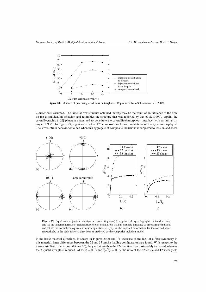
2-direction is assumed. The lamellar row structure obtained thereby may be the result of an influence of the flowon the crystallization behavior, and resembles the structure that was reported by Pan et al. (1990). Again, thecrystallographic {102} planes are assumed to constitute the crystalline/amorphous interface, with an initial tiltangle of 9.7◦. In Figure 29, a generated set of 125 composite inclusion orientations of this type are displayed.The stress–strain behavior obtained when this aggregate of composite inclusions is subjected to tension and shear
(a)
3
2
(100)
3
2
(b)
(010)
3
2
(c)
(001)
3
2
(d)
lamellar normals
ln(λ) 23
√3γ
σeq
/τ 0
σeq
/τ 0
00
00 0.10.1 0.20.2
22
44
66
88
101011 tension22 tension33 tension
13 shear12 shear
23 shear
(e) (f)
Figure 29: Equal area projection pole figures representing (a)–(c) the principal crystallographic lattice directions,and (d) the lamellar normals of an anisotropic set of orientations with an assumed influence of processing conditionsand (e), (f) the normalized equivalent mesoscopic stress σ eq/τ0, vs. the imposed deformation for tension and shear,respectively, in the basic material directions as predicted by the composite inclusion model.
in the basic material directions, is shown in Figures 29(e) and (f). Because of the lack of a fiber symmetry inthis material, large differences between the 22 and 33 tensile loading configurations are found. With respect to thetranscrystallized orientations (Figure 20), the yield strength in the 22-direction has considerably increased, whereasthe 33 yield strength is reduced. At ln(λ) = 0.05 and 2
3
√3γ = 0.05, the ratio of the 22 tensile and 12 shear yield
25
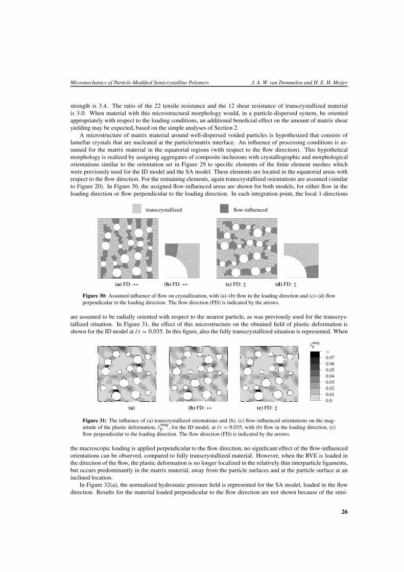
Micromechanics of Particle-Modified Semicrystalline Polymers J. A. W. van Dommelen and H. E. H. Meijer
strength is 3.4. The ratio of the 22 tensile resistance and the 12 shear resistance of transcrystallized materialis 3.0. When material with this microstructural morphology would, in a particle-dispersed system, be orientedappropriately with respect to the loading conditions, an additional beneficial effect on the amount of matrix shearyielding may be expected, based on the simple analyses of Section 2.
A microstructure of matrix material around well-dispersed voided particles is hypothesized that consists oflamellar crystals that are nucleated at the particle/matrix interface. An influence of processing conditions is as-sumed for the matrix material in the equatorial regions (with respect to the flow direction). This hypotheticalmorphology is realized by assigning aggregates of composite inclusions with crystallographic and morphologicalorientations similar to the orientation set in Figure 29 to specific elements of the finite element meshes whichwere previously used for the ID model and the SA model. These elements are located in the equatorial areas withrespect to the flow direction. For the remaining elements, again transcrystallized orientations are assumed (similarto Figure 20). In Figure 30, the assigned flow-influenced areas are shown for both models, for either flow in theloading direction or flow perpendicular to the loading direction. In each integration point, the local 1-directions
transcrystallized flow-influenced
(a) FD: ↔ (b) FD: ↔ (c) FD: � (d) FD: �Figure 30: Assumed influence of flow on crystallization, with (a)–(b) flow in the loading direction and (c)–(d) flowperpendicular to the loading direction. The flow direction (FD) is indicated by the arrows.
are assumed to be radially oriented with respect to the nearest particle, as was previously used for the transcrys-tallized situation. In Figure 31, the effect of this microstructure on the obtained field of plastic deformation isshown for the ID model at εt = 0.035. In this figure, also the fully transcrystallized situation is represented. When
εmagp
0.00.010.020.030.040.050.060.07>
(a) (b) FD: ↔ (c) FD: �
Figure 31: The influence of (a) transcrystallized orientations and (b), (c) flow-influenced orientations on the mag-nitude of the plastic deformation, ε
magp , for the ID model, at εt = 0.035, with (b) flow in the loading direction, (c)
flow perpendicular to the loading direction. The flow direction (FD) is indicated by the arrows.
the macroscopic loading is applied perpendicular to the flow direction, no significant effect of the flow-influencedorientations can be observed, compared to fully transcrystallized material. However, when the RVE is loaded inthe direction of the flow, the plastic deformation is no longer localized in the relatively thin interparticle ligaments,but occurs predominantly in the matrix material, away from the particle surfaces and at the particle surface at aninclined location.
In Figure 32(a), the normalized hydrostatic pressure field is represented for the SA model, loaded in the flowdirection. Results for the material loaded perpendicular to the flow direction are not shown because of the simi-
26
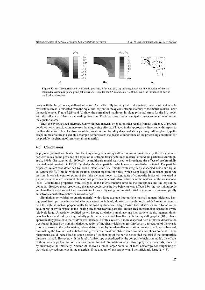
Micromechanics of Particle-Modified Semicrystalline Polymers J. A. W. van Dommelen and H. E. H. Meijer
p/τ0
−3.1−2.7−2.2−1.8−1.3−0.89−0.44
0.0
σmax/τ0
0.01.12.13.24.25.36.37.4
(a) (b) (c)
Figure 32: (a) The normalized hydrostatic pressure, p/τ0 and (b), (c) the magnitude and the direction of the nor-malized maximum in-plane principal stress, σmax/τ0, for the SA model, at εt = 0.075, with the influence of flow inthe loading direction.
larity with the fully transcrystallized situation. As for the fully transcrystallized situation, the area of peak tensilehydrostatic stress is relocated from the equatorial region for the quasi isotropic material to the matrix material nearthe particle pole. Figure 32(b) and (c) show the normalized maximum in-plane principal stress for the SA modelwith the influence of flow in the loading direction. The largest maximum principal stresses are again observed inthe equatorial area.
Thus, the hypothesized microstructure with local material orientations that results from an influence of processconditions on crystallization increases the toughening effects, if loaded in the appropriate direction with respect tothe flow direction. Then, localization of deformation is replaced by dispersed shear yielding. Although an hypoth-esized microstructure is used, this example demonstrates the possible importance of the processing conditions forthe particle-toughening of semicrystalline material.
4.6 Conclusions
A physically-based mechanism for the toughening of semicrystalline polymeric materials by the dispersion ofparticles relies on the presence of a layer of anisotropic transcrystallized material around the particles (Muratogluet al., 1995c; Bartczak et al., 1999a,b). A multiscale model was used to investigate the effect of preferentiallyoriented matrix material in HDPE blended with rubber particles, which were assumed to be cavitated. The particle-dispersed system was described by both a plane strain RVE model with irregularly dispersed voids and by anaxisymmetric RVE model with an assumed regular stacking of voids, which were loaded in constant strain ratetension. In each integration point of the finite element model, an aggregate of composite inclusions was used asa representative microstructural element that provides the constitutive behavior of the material at the mesoscopiclevel. Constitutive properties were assigned at the microstructural level to the amorphous and the crystallinedomains. Besides these properties, the mesoscopic constitutive behavior was affected by the crystallographicand lamellar orientations of the composite inclusions. By using preferential initial orientations, a mesoscopicallyanisotropic constitutive behavior was obtained.
Simulations on voided polymeric material with a large average interparticle matrix ligament thickness, hav-ing quasi isotropic constitutive behavior at a mesoscopic level, showed a strongly localized deformation, along apath through the matrix, perpendicular to the loading direction. Large tensile triaxial stresses were found in theequator region (with respect to the loading direction) near the particles. In this area, interlamellar separations wererelatively large. A particle-modified system having a relatively small average interparticle matrix ligament thick-ness has been realized by using initially preferentially oriented lamellae, with the crystallographic (100) planesapproximately parallel to the void/matrix interface. For this system, a more dispersed field of plastic deformationwas found, induced by a small relative reduction of the shear yield strength. Moreover, a relocation of the tensiletriaxial stresses in the polar region, where deformation by interlamellar separation remains small, was observed,diminishing the likeliness of initiation and growth of critical crazelike features in the amorphous domains. Thesephenomena could indeed lead to some degree of toughening of the particle-modified material if the interparticledistance is small. However, with the level of anisotropy as predicted by the composite inclusion model, the effectsof these locally preferential orientations remain limited. Simulations on idealized polymeric materials, modeledby anisotropic Hill plasticity (Section 2), showed a much larger potential of local anisotropy for toughening ofparticle-dispersed semicrystalline materials, if the amount of anisotropy would be sufficiently large (ζ > 3).
27
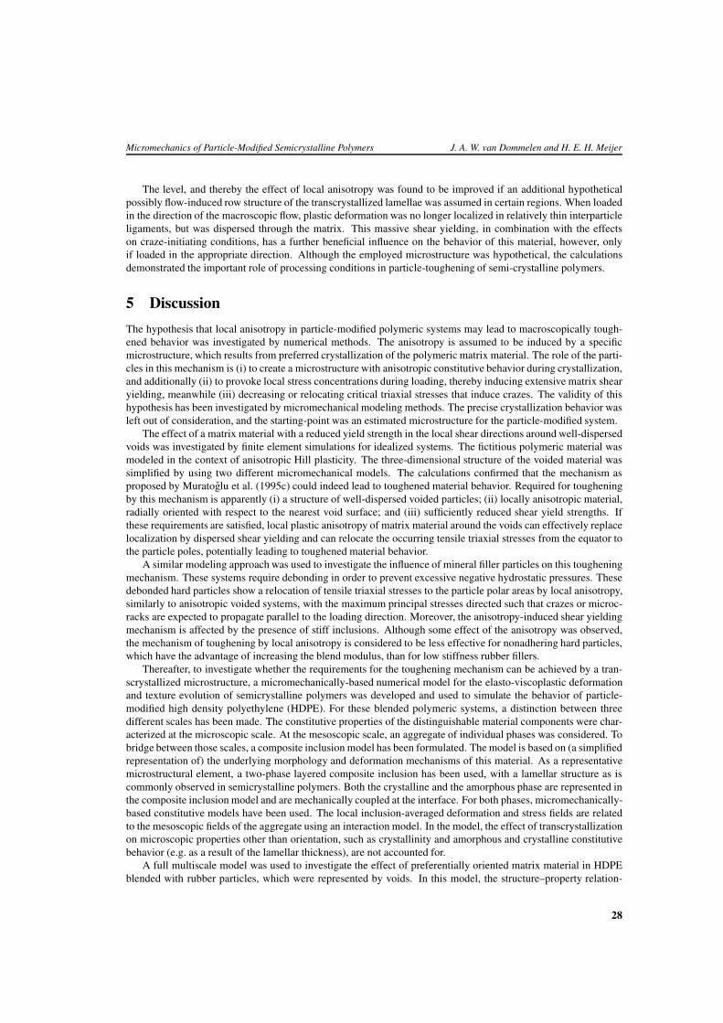
Micromechanics of Particle-Modified Semicrystalline Polymers J. A. W. van Dommelen and H. E. H. Meijer
The level, and thereby the effect of local anisotropy was found to be improved if an additional hypotheticalpossibly flow-induced row structure of the transcrystallized lamellae was assumed in certain regions. When loadedin the direction of the macroscopic flow, plastic deformation was no longer localized in relatively thin interparticleligaments, but was dispersed through the matrix. This massive shear yielding, in combination with the effectson craze-initiating conditions, has a further beneficial influence on the behavior of this material, however, onlyif loaded in the appropriate direction. Although the employed microstructure was hypothetical, the calculationsdemonstrated the important role of processing conditions in particle-toughening of semi-crystalline polymers.
5 Discussion
The hypothesis that local anisotropy in particle-modified polymeric systems may lead to macroscopically tough-ened behavior was investigated by numerical methods. The anisotropy is assumed to be induced by a specificmicrostructure, which results from preferred crystallization of the polymeric matrix material. The role of the parti-cles in this mechanism is (i) to create a microstructure with anisotropic constitutive behavior during crystallization,and additionally (ii) to provoke local stress concentrations during loading, thereby inducing extensive matrix shearyielding, meanwhile (iii) decreasing or relocating critical triaxial stresses that induce crazes. The validity of thishypothesis has been investigated by micromechanical modeling methods. The precise crystallization behavior wasleft out of consideration, and the starting-point was an estimated microstructure for the particle-modified system.
The effect of a matrix material with a reduced yield strength in the local shear directions around well-dispersedvoids was investigated by finite element simulations for idealized systems. The fictitious polymeric material wasmodeled in the context of anisotropic Hill plasticity. The three-dimensional structure of the voided material wassimplified by using two different micromechanical models. The calculations confirmed that the mechanism asproposed by Muratoglu et al. (1995c) could indeed lead to toughened material behavior. Required for tougheningby this mechanism is apparently (i) a structure of well-dispersed voided particles; (ii) locally anisotropic material,radially oriented with respect to the nearest void surface; and (iii) sufficiently reduced shear yield strengths. Ifthese requirements are satisfied, local plastic anisotropy of matrix material around the voids can effectively replacelocalization by dispersed shear yielding and can relocate the occurring tensile triaxial stresses from the equator tothe particle poles, potentially leading to toughened material behavior.
A similar modeling approach was used to investigate the influence of mineral filler particles on this tougheningmechanism. These systems require debonding in order to prevent excessive negative hydrostatic pressures. Thesedebonded hard particles show a relocation of tensile triaxial stresses to the particle polar areas by local anisotropy,similarly to anisotropic voided systems, with the maximum principal stresses directed such that crazes or microc-racks are expected to propagate parallel to the loading direction. Moreover, the anisotropy-induced shear yieldingmechanism is affected by the presence of stiff inclusions. Although some effect of the anisotropy was observed,the mechanism of toughening by local anisotropy is considered to be less effective for nonadhering hard particles,which have the advantage of increasing the blend modulus, than for low stiffness rubber fillers.
Thereafter, to investigate whether the requirements for the toughening mechanism can be achieved by a tran-scrystallized microstructure, a micromechanically-based numerical model for the elasto-viscoplastic deformationand texture evolution of semicrystalline polymers was developed and used to simulate the behavior of particle-modified high density polyethylene (HDPE). For these blended polymeric systems, a distinction between threedifferent scales has been made. The constitutive properties of the distinguishable material components were char-acterized at the microscopic scale. At the mesoscopic scale, an aggregate of individual phases was considered. Tobridge between those scales, a composite inclusion model has been formulated. The model is based on (a simplifiedrepresentation of) the underlying morphology and deformation mechanisms of this material. As a representativemicrostructural element, a two-phase layered composite inclusion has been used, with a lamellar structure as iscommonly observed in semicrystalline polymers. Both the crystalline and the amorphous phase are represented inthe composite inclusion model and are mechanically coupled at the interface. For both phases, micromechanically-based constitutive models have been used. The local inclusion-averaged deformation and stress fields are relatedto the mesoscopic fields of the aggregate using an interaction model. In the model, the effect of transcrystallizationon microscopic properties other than orientation, such as crystallinity and amorphous and crystalline constitutivebehavior (e.g. as a result of the lamellar thickness), are not accounted for.
A full multiscale model was used to investigate the effect of preferentially oriented matrix material in HDPEblended with rubber particles, which were represented by voids. In this model, the structure–property relation-
28
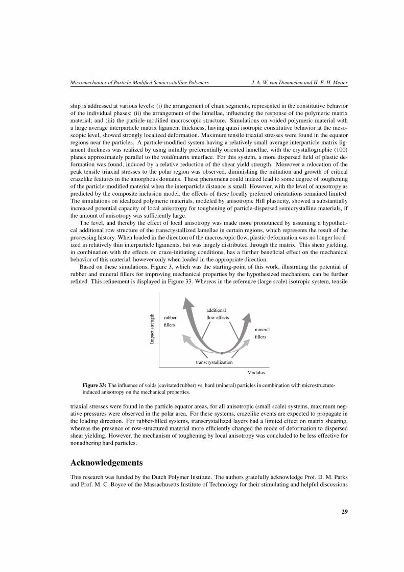
Micromechanics of Particle-Modified Semicrystalline Polymers J. A. W. van Dommelen and H. E. H. Meijer
ship is addressed at various levels: (i) the arrangement of chain segments, represented in the constitutive behaviorof the individual phases; (ii) the arrangement of the lamellae, influencing the response of the polymeric matrixmaterial; and (iii) the particle-modified macroscopic structure. Simulations on voided polymeric material witha large average interparticle matrix ligament thickness, having quasi isotropic constitutive behavior at the meso-scopic level, showed strongly localized deformation. Maximum tensile triaxial stresses were found in the equatorregions near the particles. A particle-modified system having a relatively small average interparticle matrix lig-ament thickness was realized by using initially preferentially oriented lamellae, with the crystallographic (100)
planes approximately parallel to the void/matrix interface. For this system, a more dispersed field of plastic de-formation was found, induced by a relative reduction of the shear yield strength. Moreover a relocation of thepeak tensile triaxial stresses to the polar region was observed, diminishing the initiation and growth of criticalcrazelike features in the amorphous domains. These phenomena could indeed lead to some degree of tougheningof the particle-modified material when the interparticle distance is small. However, with the level of anisotropy aspredicted by the composite inclusion model, the effects of these locally preferred orientations remained limited.The simulations on idealized polymeric materials, modeled by anisotropic Hill plasticity, showed a substantiallyincreased potential capacity of local anisotropy for toughening of particle-dispersed semicrystalline materials, ifthe amount of anisotropy was sufficiently large.
The level, and thereby the effect of local anisotropy was made more pronounced by assuming a hypotheti-cal additional row structure of the transcrystallized lamellae in certain regions, which represents the result of theprocessing history. When loaded in the direction of the macroscopic flow, plastic deformation was no longer local-ized in relatively thin interparticle ligaments, but was largely distributed through the matrix. This shear yielding,in combination with the effects on craze-initiating conditions, has a further beneficial effect on the mechanicalbehavior of this material, however only when loaded in the appropriate direction.
Based on these simulations, Figure 3, which was the starting-point of this work, illustrating the potential ofrubber and mineral fillers for improving mechanical properties by the hypothesized mechanism, can be furtherrefined. This refinement is displayed in Figure 33. Whereas in the reference (large scale) isotropic system, tensile
Modulus
Impa
ctst
reng
th
fillers
fillers
rubber
mineral
additional
flow effects
transcrystallization
Figure 33: The influence of voids (cavitated rubber) vs. hard (mineral) particles in combination with microstructure-induced anisotropy on the mechanical properties.
triaxial stresses were found in the particle equator areas, for all anisotropic (small scale) systems, maximum neg-ative pressures were observed in the polar area. For these systems, crazelike events are expected to propagate inthe loading direction. For rubber-filled systems, transcrystallized layers had a limited effect on matrix shearing,whereas the presence of row-structured material more efficiently changed the mode of deformation to dispersedshear yielding. However, the mechanism of toughening by local anisotropy was concluded to be less effective fornonadhering hard particles.
Acknowledgements
This research was funded by the Dutch Polymer Institute. The authors gratefully acknowledge Prof. D. M. Parksand Prof. M. C. Boyce of the Massachusetts Institute of Technology for their stimulating and helpful discussions
29
Micromechanics of Particle-Modified Semicrystalline Polymers J. A. W. van Dommelen and H. E. H. Meijer
concerning the micromechanical modeling of semicrystalline polymers and Dr. B. A. G. Schrauwen for the valu-able contributions to this research.
References
ARGON, A. S. (1997). Morphological mechanisms and kinetics of large-strain plastic deformation and evolutionof texture in semi-crystalline polymers. Journal of Computer-Aided Materials Design, 4, 75–98.
ARGON, A. S., COHEN, R. E., GEBIZLIOGLU, O. S., and SCHWIER, C. E. (1983). Crazing in block copolymersand blends. H.-H. KAUSCH (ed.). Advances in Polymer Science, 52/53, 275–334. Springer-Verlag, Berlin.
ARGON, A. S., COHEN, R. E., and MOWER, T. M. (1994). Mechanisms of toughening brittle polymers. Mate-rials Science and Engineering A, 176, 79–90.
ARRUDA, E. M. and BOYCE, M. C. (1993). A three-dimensional constitutive model for the large stretch behaviorof rubber elastic material. Journal of the Mechanics and Physics of Solids, 41, 389–412.
BARTCZAK, Z., ARGON, A. S., COHEN, R. E., and WEINBERG, M. (1999a). Toughness mechanism in semi-crystalline polymer blends: I. High-density polyethylene toughened with rubbers. Polymer, 40, 2331–2346.
BARTCZAK, Z., ARGON, A. S., COHEN, R. E., and WEINBERG, M. (1999b). Toughness mechanism in semi-crystalline polymer blends: II. High-density polyethylene toughened with calcium carbonate filler particles.Polymer, 40, 2347–2365.
BARTCZAK, Z., ARGON, A. S., COHEN, R. E., and KOWALEWSKI, T. (1999c). The morphology and orienta-tion of polyethylene in films of sub-micron thickness crystallized in contact with calcite and rubber substrates.Polymer, 40, 2367–2380.
BASSETT, D. C. and HODGE, A. M. (1981). On the morphology of melt-crystallized polyethylene I. Lamellarprofiles. Proceedings of the Royal Society of London A, 377, 25–37.
BICERANO, J. and SEITZ, J. T. (1996). Molecular origins of toughness in polymers. C. B. ARENDS (ed.).Polymer toughening, 1–59. Marcel Dekker, New York.
BORGGREVE, R. J. M., GAYMANS, R. J., SCHUIJER, J., and INGEN HOUSZ, J. F. (1987). Brittle-toughtransition in nylon-rubber blends: effect of rubber concentration and particle size. Polymer, 28, 1489–1496.
CHACKO, V. P., KARASZ, F. E., FARRIS, R. J., and THOMAS, E. L. (1982). Morphology of CaCO3-filledpolyethylenes. Journal of Polymer Science: Part B: Polymer Physics, 20, 2177–2195.
DIJKSTRA, K. and TEN BOLSCHER, G. H. (1994). Nylon-6/rubber blends. Part III. Stresses in and around rubberparticles and cavities in a nylon matrix. Journal of Materials Science, 29, 4286–4293.
VAN DOMMELEN, J. A. W., PARKS, D. M., BOYCE, M. C., BREKELMANS, W. A. M., and BAAIJENS, F.P. T. (2001). Multi-scale modeling of the constitutive behavior of semi-crystalline polymers. In Proceedings ofthe European Conference on Computational Mechanics, Cracow, Poland.
VAN DOMMELEN, J. A. W., PARKS, D. M., BOYCE, M. C., BREKELMANS, W. A. M., and BAAIJENS, F.P. T. (2003a). Micromechanical modeling of intraspherulitic deformation of semicrystalline polymers. Polymer.accepted.
VAN DOMMELEN, J. A. W., BREKELMANS, W. A. M., and BAAIJENS, F. P. T. (2003b). Micromechanicalmodeling of particle-toughening of polymers by locally induced anisotropy. Mechanics of Materials, 35, 845–863.
VAN DOMMELEN, J. A. W., PARKS, D. M., BOYCE, M. C., BREKELMANS, W. A. M., and BAAIJENS, F.P. T. (2003c). Micromechanical modeling of the elasto-viscoplastic behavior of semi-crystalline polymers.Journal of the Mechanics and Physics of Solids, 51, 519–541.
VAN DOMMELEN, J. A. W., BREKELMANS, W. A. M., and BAAIJENS, F. P. T. (2003d). Multiscale modelingof particle-modified polyethylene. Journal of Materials Science. Submitted.
VAN DOMMELEN, J. A. W., BREKELMANS, W. A. M., and BAAIJENS, F. P. T. (2003e). A numerical investiga-tion of the potential of rubber and mineral particles for toughening of semicrystalline polymers. ComputationalMaterials Science, 27, 480–492.
ESTEVEZ, R., TIJSSENS, M. G. A., and VAN DER GIESSEN, E. (2000). Modeling of the competition betweenshear yielding and crazing in glassy polymers. Journal of the Mechanics and Physics of Solids, 48, 2585–2617.
FRANK, F. C., GUPTA, V. B., and WARD, I. M. (1970). The effect of mechanical twinning on the tensile modulusof polyethylene. Philosophical Magazine, 21, 1127–1145.
30
Micromechanics of Particle-Modified Semicrystalline Polymers J. A. W. van Dommelen and H. E. H. Meijer
FRIEDRICH, K. (1983). Crazes and shear bands in semi-crystalline thermoplastics. H.-H. KAUSCH (ed.). Ad-vances in Polymer Science, 52/53, 225–274. Springer-Verlag, Berlin.
FUKUI, T., KIKUCHI, Y., and INOUE, T. (1991). Elastic-plastic analysis of the toughening mechanism in rubber-modified nylon: matrix yielding and cavitation. Polymer, 32, 2367–2371.
GAUTAM, S., BALIJEPALLI, S., and RUTLEDGE, G. C. (2000). Molecular simulations of the interlamellar phasein polymers: effect of chain tilt. Macromolecules, 33, 9136–9145.
G’SELL, C. and DAHOUN, A. (1994). Evolution of microstructure in semi-crystalline polymers under large plasticdeformation. Materials Science and Engineering A, 175, 183–199.
HKS (2001). ABAQUS/Standard User’s Manual, version 6.2. Hibbitt, Karlsson & Sorensen, Inc., Pawtucket,Rhode Island, USA.
HALL, R. (1991). Computer modelling of rubber-toughened plastics: random placement of monosized core-shellparticles in a polymer matrix and interparticle distance calculations. Journal of Materials Science, 26, 5631–5636.
HILL, R. (1950). The Mathematical Theory of Plasticity. Oxford University Press, London.KAUSCH, H.-H., GENSLER, R., GREIN, CH., PLUMMER, C. J. G., and SCARAMUZZINO, P. (1999). Crazing
in semicrystalline thermoplastics. Journal of Macromolecular Science – Physics, B38, 803–815.KELLER, A. and SAWADA, S. (1964). On the interior morphology of bulk polyethylene. Die Makromolekulare
Chemie, 74, 190–221.KIM, G.-M., LEE, D.-H., HOFFMANN, B., KRESSLER, J., and STOPPELMANN, G. (2001). Influence of
nanofillers on the deformation process in layered silicate/polyamide-12 nanocomposites. Polymer, 42, 1095–1100.
KOBAYASHI, K. and NAGASAWA, T. (1966). Mechanical properties of polyethylene crystals. II. Deformationprocess of spherulite. Journal of Polymer Science: Part C, 15, 163–183.
KRAMER, E. J. (1983). Microscopic and molecular fundamentals of crazing. H.-H. KAUSCH (ed.). Advances inPolymer Science, 52/53, 1–56. Springer-Verlag, Berlin.
LEE, B. J., PARKS, D. M., and AHZI, S. (1993a). Micromechanical modeling of large plastic deformation andtexture evolution in semi-crystalline polymers. Journal of the Mechanics and Physics of Solids, 41, 1651–1687.
LEE, B. J., ARGON, A. S., PARKS, D. M., AHZI, S., and BARTCZAK, Z. (1993b). Simulation of large strainplastic deformation and texture evolution in high density polyethylene. Polymer, 34, 3555–3575.
LIN, L. and ARGON, A. S. (1994). Structure and plastic deformation of polyethylene. Journal of MaterialsScience, 29, 294–323.
LOYENS, W. and GROENINCKX, G. (2002). Ultimate mechanical properties of rubber toughened semicrystallinePET at room temperature. Polymer, 43, 5679–5691.
LOYENS, W. and GROENINCKX, G. (2003). Rubber toughened semicrystalline PET: influence of the matrixproperties and test temperature. Polymer, 44, 123–136.
MARGOLINA, A. and WU, S. (1988). Percolation model for brittle-tough transition in nylon/rubber blends.Polymer, 29, 2170–2173.
MEIJER, H. E. H. and GOVAERT, L. E. (2003). Multi-scale analysis of mechanical properties of amorphouspolymer systems. Macromolecular Chemistry and Physics, 204, 274–288.
MICHLER, G. H. (1999). Micromechanics of polymers. Journal of Macromolecular Science – Physics, B38,787–802.
MICHLER, G. H. and GODEHARDT, R. (2000). Deformation mechanisms of semicrystalline polymers on thesubmicron scale. Crystal Research and Technology, 35, 863–875.
MURATOGLU, O. K., ARGON, A. S., and COHEN, R. E. (1995a). Crystalline morphology of polyamide-6 nearplanar surfaces. Polymer, 36, 2143–2152.
MURATOGLU, O. K., ARGON, A. S., COHEN, R. E., and WEINBERG, M. (1995b). Microstructural processesof fracture of rubber-modified polyamides. Polymer, 36, 4771–4786.
MURATOGLU, O. K., ARGON, A. S., and COHEN, R. E. (1995c). Toughening mechanism of rubber-modifiedpolyamides. Polymer, 36, 921–930.
NAM, P. H., MAITI, P., OKAMOTO, M., KOTAKA, T., HASEGAWA, N., and USUKI, A. (2001). A hierarchicalstructure and properties of intercalated polypropylene/clay nanocomposites. Polymer, 42, 9633–9640.
31
Micromechanics of Particle-Modified Semicrystalline Polymers J. A. W. van Dommelen and H. E. H. Meijer
NARISAWA, I. and ISHIKAWA, M. (1990). Crazing in semicrystalline thermoplastics. H.-H. KAUSCH (ed.).Advances in Polymer Science, 91/92, 353–391. Springer-Verlag, Berlin.
PAN, S. J., IM, J., HILL, M. J., KELLER, A., HILTNER, A., and BAER, E. (1990). Structure of ultrathinpolyethylene layers in multilayer films. Journal of Polymer Science: Part B: Polymer Physics, 28, 1105–1119.
PETERMANN, J. and EBENER, H. (1999). On the micromechanics of plastic deformation in semicrystallinepolymers. Journal of Macromolecular Science – Physics, B38, 837–846.
RAMSTEINER, F. and HECKMANN, W. (1985). Mode of deformation in rubber-modified polyamide. PolymerCommunications, 200, 199–200.
RYBNIKAR, F. (1981). Interactions in the system polyethylene–solid filler. Journal of Macromolecular Science –Physics, B19, 1–11.
RYBNIKAR, F. (1989). Orientation in Composite of Polypropylene and Talc. Journal of Applied Polymer Science,38, 1479–1490.
SANCHEZ-SOLIS, A., ESTRADA, M. R., CRUZ, J., and MANERO, O. (2000). On the properties and processing ofpolyethylene terephthalate/styrene-butadiene rubber blend. Polymer Engineering and Science, 40, 1216–1225.
SCHRAUWEN, B. A. G., GOVAERT, L. E., and MEIJER, H. E. H. (2001a). Toughness of high-density polyethy-lene with hard filler particles. In Proceedings of the Seventeenth Annual Meeting of the Polymer ProcessingSociety, Montreal, Canada.
SCHRAUWEN, B. A. G., GOVAERT, L. E., PETERS, G. W. M., and MEIJER, H. E. H. (2001b). The influenceof flow induced crystallization on the impact toughness of high-density polyethylene. In Proceedings of theInternational Conference on Flow Induced Crystallization of Polymers, Salerno, Italy.
SCHRAUWEN, B. A. G., GOVAERT, L. E., PETERS, G. W. M., and MEIJER, H. E. H. (2002). The influence offlow-induced crystallization on the impact toughness of high-density polyethylene. Macromolecular Symposia,185, 89–102.
SMIT, R. J. M., BREKELMANS, W. A. M., and MEIJER, H. E. H. (1998). Prediction of the mechanical behaviorof non-linear heterogeneous systems by multi-level finite element modeling. Computer Methods in AppliedMechanics and Engineering, 155, 181–192.
SMIT, R. J. M., BREKELMANS, W. A. M., and MEIJER, H. E. H. (1999). Prediction of the large-strain mechan-ical response of heterogeneous polymer systems: local and global deformation behaviour of a representativevolume element of voided polycarbonate. Journal of the Mechanics and Physics of Solids, 47, 201–221.
SOCRATE, S. and BOYCE, M. C. (2000). Micromechanics of toughened polycarbonate. Journal of the Mechanicsand Physics of Solids, 48, 233–275.
SOCRATE, S., BOYCE, M. C., and LAZZERI, A. (2001). A micromechanical model for multiple crazing in highimpact polystyrene. Mechanics of Materials, 33, 155–175.
THIO, Y. S., ARGON, A. S., COHEN, R. E., and WEINBERG, M. (2002). Toughening of isotactic polypropylenewith CaCO3 particles. Polymer, 43, 3661–3674.
TIJSSENS, M. G. A., VAN DER GIESSEN, E., and SLUYS, L. J. (2000). Modeling of crazing using a cohesivesurface methodology. Mechanics of Materials, 32, 19–35.
TVERGAARD, V. (1996). Effect of void size difference on growth and cavitation instabilities. Journal of theMechanics and Physics of Solids, 44, 1237–1253.
TVERGAARD, V. (1998). Interaction of very small voids with larger voids. International Journal of Solids andStructures, 30, 3989–4000.
TZIKA, P. A., BOYCE, M. C., and PARKS, D. M. (2000). Micromechanics of deformation in particle-toughenedpolyamides. Journal of the Mechanics and Physics of Solids, 48, 1893–1930.
WILBRINK, M. W. L., ARGON, A. S., COHEN, R. E., and WEINBERG, M. (2001). Toughenability of nylon-6with CaCO3 filler particles: new findings and general principles. Polymer, 42, 10155–10180.
WU, S. (1985). Phase structure and adhesion in polymer blends: a criterion for rubber toughening. Polymer, 26,1855–1863.
WU, S. (1988). A generalized criterion for rubber toughening: the critical matrix ligament thickness. Journal ofApplied Polymer Science, 35, 549–561.
YOUNG, R. J. and BOWDEN, P. B. (1974). Twinning and martensitic transformations in oriented high-densitypolyethylene. The Philosophical Magazine, 29, 1061–1073.
ZUIDERDUIN, W. C. J., WESTZAAN, C., HUETINK, J., and GAYMANS, R. J. (2003). Toughening of polypropy-lene with calcium carbonate particles. Polymer, 44, 261–275.
32


![A New Cost Function for Parameter Estimation of Chaotic ...sprott.physics.wisc.edu/pubs/paper388.pdf · Quantum-behaved particle swarm optimization [Yang et al., 2009] Modified ant](https://img.pdfslide.net/doc/110x75/5a8b129e7f8b9a7f398c0ca9/a-new-cost-function-for-parameter-estimation-of-chaotic-particle-swarm-optimization.jpg)


![Electrochemical study of modified bis-[triethoxysilylpropyl ...gecea.ist.utl.pt/Publications/FM/2007-06.pdf · Electrochemical study of modified bis-[triethoxysilylpropyl] tetrasulfide](https://img.pdfslide.net/doc/110x75/5f7f0c293f91253169396244/electrochemical-study-of-modiied-bis-triethoxysilylpropyl-geceaistutlptpublicationsfm2007-06pdf.jpg)