Embed Size (px)
Citation preview

Site Evaluation for Stormwater Infiltration(WISCONSIN DEPARTMENT OF NATURAL RESOURCES
CONSERVATION PRACTICE STANDARD
DRAFT SITE EVALUATION FOR STORM WATER INFILTRATION
1002)
Wisconsin Department of Natural Resources Conservation Practice
Standards
[I.] Definition
DEFINITIONThis standard defines site evaluation procedures to:
[(1)] Perform an initial screening of a development site1 to determine its suitability for infiltration.,
[(2)] Evaluate each area within a development site that is selected for infiltration., and
[(3)] Prepare a site evaluation report.
[II.] Purpose
PURPOSE(1) Protect groundwater from surface water pollution sources,
(2) Identify areas suitable for infiltration,
(3) Establish methodologiesmethods to a) characterize the site, and b) screen for exclusions and exemptions under Chapterch. NR 151, Wis. Adm. code.Code,
[(1)] Establish requirements for siting an infiltration device and the selection of design infiltration rates.,
[(2)] Define requirements for a site evaluation report documenting that insures appropriate areas are selected for infiltration and that an appropriate design infiltration rate is used., and
[III.] Conditions where Practice Applies
[(3)] Define requirements for measuring infiltration in existing vegetated swales and calculating a dynamic infiltration rate in existing vegetated swales.
CONDITIONS WHERE PRACTICE APPLIES
1 Words in the standard that are shown in italics are described in VIII.the Definitions section. The words are italicized the first time they are used in the text.Conservation Practice Standards are reviewed periodically and updated if needed. To obtain the current version of this standard, contact your local WDNR office or the Standards Oversight Council office in Madison, WI at (608) 441-2677.
WDNRDRAFT
12
3
4
5
6
789
1011121314
15
1617
1819
2021
22232425
26
27
2829
303132
333435
3637383940
4142
1

1002-CPS-2
This standard is intended for development sites being considered for stormwaterstorm water infiltration devices., and also includes a method to establish an infiltration rate for existing swales. Additional site location requirements may be imposed by other stormwaterstorm water infiltration device technical standards.
[IV.] Federal, State and Local Laws
Users of this standard shall beBe aware of applicable federal, state and local laws, rules, regulations or permit requirements governing infiltration devices. This standard does not contain the text of federal, state or local laws. Note that infiltration devices are commonly regulated as plumbing when in connection with a piping system, see ch. SPS 382, Wis. Adm. Code.
[V.] Criteria
CRITERIA
The site evaluation consists of four steps (Steps A – D) for locating the optimal areas for infiltration, and establishing the design infiltration rate for properly sizing infiltration devices (below, and Figure 1). Additionally, Step C.2. (Infiltration Option 4) addresses measuring dynamic infiltration rates in existing vegetated swales.
2 WDNRDRAFT XX/2017
43444546
47484950515253
54
555657
58596061
62
23

1002-CPS-3
Step A. Initial Site Screening.
Step B. Preliminary Field Verification of information collected in Step A.the Initial Site Screening
Step C. Establishment of Design Infiltration Rate
Step C.1. Field Evaluation of Specific Infiltration Areas.
Step C.2. Infiltration Rate Determination
Infiltration Option 1 – Infiltration Rate Not Measured, Soil Compaction Mitigated
Infiltration Option 2 – Infiltration Rate Measured with In-Field Device, Soil Compaction Mitigated
Infiltration Option 3 – Infiltration Rate Not Measured, Soil Compaction Not Mitigated
Infiltration Option 4 – Infiltration Rate of Existing Vegetated Swales
Step D. Soil and Site Evaluation Reporting.Report
The steps shall coincide,Figures and Attachments:
Figure 1. Site Evaluation for Infiltration Flow Chart of Steps
Figure 2. Example Bioretention Basin Section
Figure 3. Example Bioretention Basin Section with Underdrain Section
Figure 4. Example Infiltration Basin Section
Attachment 1. Soil and Site Evaluation Form
Attachment 2. Technical Note for Infiltration in Compacted Soils
In order to efficiently evaluate a site for infiltration, it is advantageous to perform the investigation in strict accordance with local ordinance. The final location for infiltration devices may be impacted by local permitting requirements. Permitting process requirements for development sites vary across the state and may vary within a municipality depending on the number of lots being developed. To avoid costly redesigns, complete Step A before the preliminary plat, and Step B before the final plat or Certified Survey Map (CSM) is approved. For regional infiltration devices, and for devices constructed on public right-of-ways, public land, or jointly owned land, complete Step C before the final plat or final CSM approval.
Record information for Steps B and C as noted in Step D. Prepare a single report for the infiltration investigation.
Step A. much as possible, for when theInitial Site Screening
The purpose of the initial site screening is to use existing available information is needed to determine the following: 1) the to identify potential for infiltration on the site, 2) the optimal locations for infiltration devices, and 3) the design of the infiltration device(s). Steps A and B shall be completed as soon as possible in the approval process. See Consideration VI.M for an example based on in situ soil conditions..
Step A. Initial Screening
The initial screening identifies potential locations for infiltration devices. The purpose of the initial site screening is towill also determine if installation is limited by sss. NR 151.12(5)(c)5.124 (3)(a) or NR 151.12(5)(c)6.,(4), Wis. Adm. Code, and to determine where field work is needed for Step B. Optimal
3 WDNRDRAFT XX/2017
63
64
65
66
67
68
6970
71
72
73
74
75
76
77
78
79
80
81
8283848586878889
9091
92
93
9495969798
99100101102103104
45
1002-CPS-4
locations for infiltration testing are verifiedconfirmed in Step B.
Information collected in Step A will be used to explore the potential for multiple infiltration areas versus relying on a regional infiltration device. Smaller infiltrationInfiltration devices dispersed around a development are usually more sustainablebetter able to sustain the existing hydrology than a single regional device that is more likely to have maintenance and groundwater mounding problems..
4 WDNRDRAFT XX/2017
105
106107108109110
111
67

1002-CPS-5
The initial screening shall may be conducted without fieldwork to determine the following: Note: Useful
(See a list of references for the existing resource maps and information are listedresources in the Considerations VI.I and J.section)
[(1)] Copy of official soil survey map of the site as found on the USDA-NRCS Web Soil Survey, including soils legend,
(1) Site topography map and slopes greater than 20%.%,
[(2)] Site soil infiltration capacity characteristics as defined in NRCS County soil surveys. or other relevant source,
[(3)] Soil parent material. obtained from published soil descriptions,
[(4)] Regional or localNRCS Climate Analysis for Wetlands Tables (WETS Tables),
(2) Soil map unit, depth to groundwater and bedrock. Usedepth to restrictive features; use seasonally high groundwater information where available.,
[(5)] Distance to sites listed on the GIS Registry of ClosedWisconsin Remediation and Redevelopment Database (WRRD) sites within 500 feet from the perimeter of the development site.,
[1.] Distance to sites listed on the Bureau of Remediation and Redevelopment Tracking System within 500 feet from the perimeter of the development site.[(6)] PresenceKnown presence of endangered species habitat.,
[(7)] Presence of flood plains and flood fringes.,
[(8)] Location of mapped wetland, hydric soils soil and potentially hydric soil based on the USDA County Soil Survey and wetlands from the WDNR Wisconsin Wetland Inventory map.(WWI), which can be accessed via the WDNR Surface Water Data Viewer,
[(9)] Sites An evaluation of the site relative to where the installation of stormwaterstorm water infiltration devices is prohibited by s. NR 151.124(3)(a) and (4)(a), Wis. Adm. excluded,Code, including setbacks from direct conduits to groundwater such as wells, sinkholes, and karst features due to the potential for groundwater contamination, by chapter NR 151 Wis. Adm. Code.
[(10)] Sites exemptedAn evaluation of the site to determine an exemption by chapterss. NR 151.124 (3)(b) and (4)(c) Wis. Adm. Code from the requirement to install infiltration devices.,
(3) Potential impact to utilities, and
(4) Potential impact to adjacent property.
Step B. Preliminary Field Verification of the Initial Site Screening
[A.] Field verificationThe purpose of Step B is required for to field-verify information from Step A for all potential areas of the development site considered suitable for infiltration. This includes verification of Step A.1, 2, 3, 4, 9, 10 and 11.
Sites shall be testedTest the sites for depth to groundwater, depth to bedrock, and percent fines informationsoil texture to verify any exemption and exclusion found in Step A.10 and 11. The following is a description of the percent fines expected for each type of soil textural classification. Soil borings are acceptable for the preliminary investigation, but pits are required for design (refer to Step C).
5 WDNRDRAFT XX/2017
112
113114
115116117
118
119120
121
122
123124
125126127
128129130
131
132133134
135136137138139
140141
142
143
144
145
146147148149150151152153154
89
1002-CPS-6
Several textural classesSandy loams, loams, silt loams, silts and all clay textural classifications are assumed to meet the percent fines limitations of Ch.a filtering layer in s. NR 151.002(14r), Wis. Adm. 12(5)(c)5.i.Code, for both 3 and 5 foot soil layers. These classifications include the sandy loams, loams, silt loams and all the clay textural classifications. Coarse sand is the only soil texture that by definition willdoes not meet s. NR 151.002(14r), Wis. Adm. 12(5)(c)5.i.Code, limitations for a 3 foot soil layer consisting of 20% fines. Other sand textures and loamy sands may needrequire the percent fines level be verified with a laboratorysieve analysis.
A wetland determination or delineation may be needed to identify whether a wetland is present within or near the site. WDNR “Wetland Screening and Delineation Procedures,” dated Dec. 15, 2016, was developed to assist in making this decision (http://dnr.wi.gov/topic/waterways/construction/wetlands.html).
6 WDNRDRAFT XX/2017
155156157158159160161162
163164165
166
1011
1002-CPS-7
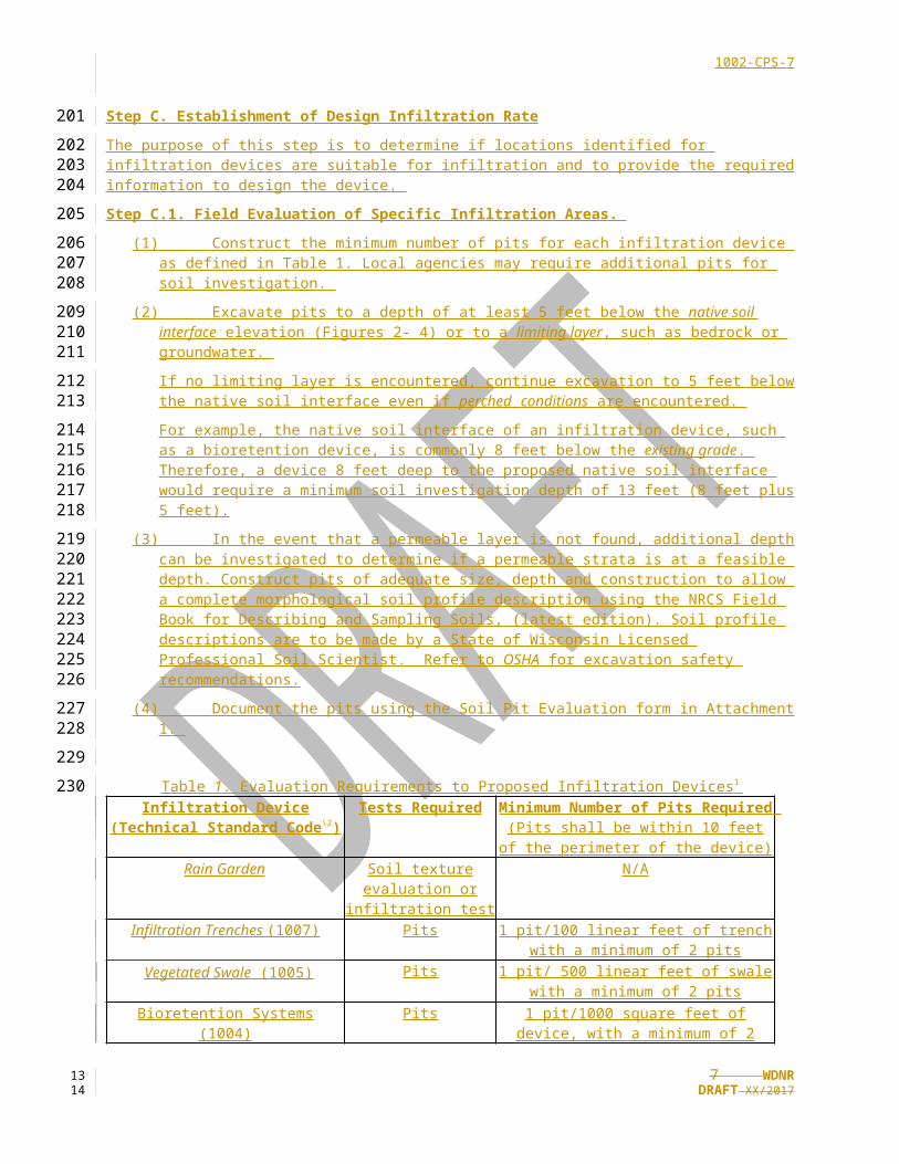
Step C. Establishment of Design Infiltration RateThe purpose of this step is to determine if locations identified for infiltration devices are suitable for infiltration and to provide the required information to design the device.
Step C.1. Field Evaluation of Specific Infiltration Areas. (1) Construct the minimum number of pits for each infiltration device as defined in Table 1. Local
agencies may require additional pits for soil investigation.
(2) Excavate pits to a depth of at least 5 feet below the native soil interface elevation (Figures 2- 4) or to a limiting layer, such as bedrock or groundwater.
If no limiting layer is encountered, continue excavation to 5 feet below the native soil interface even if perched conditions are encountered.
For example, the native soil interface of an infiltration device, such as a bioretention device, is commonly 8 feet below the existing grade. Therefore, a device 8 feet deep to the proposed native soil interface would require a minimum soil investigation depth of 13 feet (8 feet plus 5 feet).
(3) In the event that a permeable layer is not found, additional depth can be investigated to determine if a permeable strata is at a feasible depth. Construct pits of adequate size, depth and construction to allow a complete morphological soil profile description using the NRCS Field Book for Describing and Sampling Soils, (latest edition). Soil profile descriptions are to be made by a State of Wisconsin Licensed Professional Soil Scientist. Refer to OSHA for excavation safety recommendations.
(4) Document the pits using the Soil Pit Evaluation form in Attachment 1.
Table 1. Evaluation Requirements to Proposed Infiltration Devices1 Infiltration Device (Technical
Standard Code\2 )Tests Required Minimum Number of Pits Required
(Pits shall be within 10 feet of the perimeter of the device)
Rain Garden Soil texture evaluation or infiltration test
N/A
Infiltration Trenches (1007) Pits 1 pit/100 linear feet of trench with a minimum of 2 pits
Vegetated Swale (1005) Pits 1 pit/ 500 linear feet of swale with a minimum of 2 pits
Bioretention Systems (1004) Pits 1 pit/1000 square feet of device, with a minimum of 2 pits
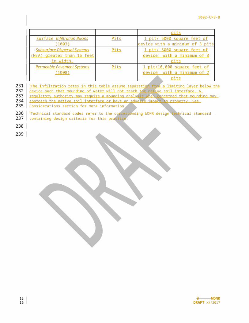
Surface Infiltration Basins (1003) Pits 1 pit/ 5000 square feet of device with a minimum of 3 pits
Subsurface Dispersal Systems (N/A) greater than 15 feet in width.
Pits 1 pit/ 5000 square feet of device, with a minimum of 3 pits
Permeable Pavement Systems (1008)
Pits 1 pit/10,000 square feet of device, with a minimum of 2 pits
1 The infiltration rates in this table assume separation from a limiting layer below the device such that mounding of water will not reach the native soil interface. A regulatory authority may require a mounding analysis when concerned that mounding may approach the native soil interface or have an adverse impact to property. See Considerations section for more information.2 Technical standard codes refer to the corresponding WDNR design technical standard containing design criteria for this practice.
7 WDNRDRAFT XX/2017
167
168169
170
171172
173174
175176
177178179
180181182183184185
186
187
188
189190191192
193194
195
196
1213
1002-CPS-8
Step C.2. Infiltration Rate Determination. The purpose of this step is to determine a design infiltration rate (Infiltration Options 1-3), or to measure the infiltration rate of existing vegetated swales (Infiltration Option 4).
To determine if a site is eligible for exemption from infiltration under s. NR 151.124(4)(c), Wis. Adm. Code, use a scientifically credible field test method unless the least permeable soil horizon within five feet below the native soil interface is one of the following: sandy clay loam, clay loam, silty clay loam, sandy clay, silty clay, or clay.
Base the infiltration rate used to request the exemption on the actual field-measured rate without the use of correction factors in Tables 3, 4, or 5.
Take at least three infiltration tests at the potential infiltration location within the native soil layer being evaluated for exemption. Distribute tests so that they best represent the area being tested. At least two-thirds of tests shall have a measured infiltration rate of less than 0.6 in/hr for the field site to be eligible for an exemption from infiltration requirements.
The geometric mean of infiltration test results should be used. However, it may be appropriate to group certain test results where an infiltration trend is apparent and assign different geometric mean rates accordingly. Grouping of results may be done based on soil type or spatial reasons to provide representative results. Where an infiltration rate is too low to measure, a rate of 0.03 in/hr may be used to calculate a geometric mean of the dataset (the dataset’s values must be greater than zero to calculate a geometric mean).
Use one of the following methods (Infiltration Options 1 – 4) to determine the design infiltration rate. Examples within Infiltration Options 1-3 calculate the static infiltration rate. Option 4 outlines the dynamic infiltration rate used to model a flowing water condition.
Note that soil compaction mitigation reduces the soil density and promotes infiltration.
Infiltration Option 1 – Infiltration Rate Not Measured , Soil Compaction Mitigated
Using information from soil pits, select the design static infiltration rate from Table 2 based on soil texture of the least permeable soil horizon within 5 feet below the native soil interface. See Example 1.
Table 2. Design Static Infiltration Rates for Soil Textures Receiving Storm water
Soil Texture Design Static Infiltration Rate Without Measurement (Inches/hour)1
Coarse sand or coarser 3.60Loamy coarse sand 3.60
Sand 3.60Loamy sand 1.63
Sandy loam, fine sand, loamy sand, very fine sand, and loamy fine sand
0.50
Loam 0.24Silt loam 0.13
Sandy clay loam 0.11Clay loam 0.03
Silty Clay loam 0.042 Sandy clay 0.04Silty clay 0.07
Clay 0.071 Infiltration rates represent the lowest value for each textural class presented in Table 2 of Rawls, 1998.2 Infiltration rate is an average based on Rawls, 1982 and Clapp & Hornberger, 1978.
8 WDNRDRAFT XX/2017
197
198199
200201202203
204205
206207208209
210211212213214215
216217218
219
220
221
222223
224
225
226
227
1415

1002-CPS-9
Where adverse soil structure is present, such as moderate to strong platy soil structure, compacted or cemented soil horizons, or massive soil conditions with high bulk density reduce the design static infiltration rates per judgment of a qualified licensed individual (see Required Qualifications).
Example 1.
(1) Calculate the design static infiltration rate (Kstatic) where the native soil interface is 4 feet below existing grade (Table E1).
Table E1. Observed Soil Conditions for Example 1
Soil Depth Below Existing Grade (Inches) Soil Texture Infiltration Rate1 (Inches/Hour)0-12 Silt Loam 0.13
12-24 Sandy Loam 0.5024-72 Loam 0.24
72 – 130 Silt Loam 0.13130 – 180 Loam 0.24
1 Infiltration rates are from Table 2.
Solution 1.
(1) K static = the soil texture with the lowest infiltration rate within 5 feet below the native soil interface
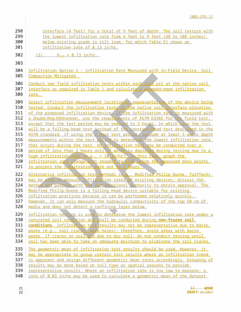
(2) Solve for Kstatic: Add 5 feet to the depth of the native soil interface (4 feet) for a total of 9 feet of depth. The soil texture with the lowest infiltration rate from 4 feet to 9 feet (48 to 108 inches) below existing grade is silt loam, for which Table E1 shows an infiltration rate of 0.13 in/hr.
(3) K static = 0.13 in/hr.
Infiltration Option 2 – Infiltration Rate Measured with In-Field Device , Soil Compaction Mitigated
Conduct two field infiltration tests within each soil pit at the native soil interface as required in Table 1 and calculate a geometric mean infiltration rate.
Select infiltration measurement location(s) representative of the device being tested. Conduct the infiltration tests at the native soil interface elevation of the proposed infiltration device. If the infiltration rate is measured with a Double-Ring Infiltrometer, use the requirements of ASTM D3385 for the field test, except that the test period may be reduced to 2 hours, in which case the test will be a falling-head test instead of the constant-head test described in the ASTM standard. If using the 2 hour test period, include at least 5 water depth measurements within the test period to determine the lowest infiltration rate that occurs during the test. An infiltration test may be conducted over a period of less than 2 hours only if water is depleted during testing due to a high infiltration rate (e.g., > 10 in/hr). In this case, graph the infiltration rate change with respect to time using the measured data points to project the infiltration rate out to 2 hours.
Alternative infiltration test methods (e.g., Modified Philip Dunne, TurfTech) may be used to measure infiltration rates of existing devices; discuss the method and purpose with the jurisdictional authority to obtain approval. The Modified Philip-Dunne is a falling head device suitable for existing infiltration practices because it can be performed relatively quickly. However, it can only measure the hydraulic conductivity of the top 50 cm of media and does not detect a confining layer below.
Infiltration testing is used to determine the lowest infiltration rate under a saturated soil condition and shall be conducted during non-frozen soil conditions. Infiltration test results may not be representative due to macro pores (e.g., soil cracks, worm holes); therefore, avoid areas with macro pores. If cracks in soil are due to dry soil, do not conduct testing until soil has been able to take on adequate moisture to eliminate the soil cracks.
9 WDNRDRAFT XX/2017
228229230
231
232233
234
235
236
237
238
239
240241242
243
244
245
246247
248249250251252253254255256257
258259260261262
263264265266267
1617

1002-CPS-10
The geometric mean of infiltration test results should be used. However, it may be appropriate to group certain test results where an infiltration trend is apparent and assign different geometric mean rates accordingly. Grouping of results may be done based on soil type or spatial reasons to provide representative results. Where an infiltration rate is too low to measure, a rate of 0.03 in/hr may be used to calculate a geometric mean of the dataset (the dataset’s values must be greater than zero to calculate a geometric mean).
To calculate the static infiltration rate,
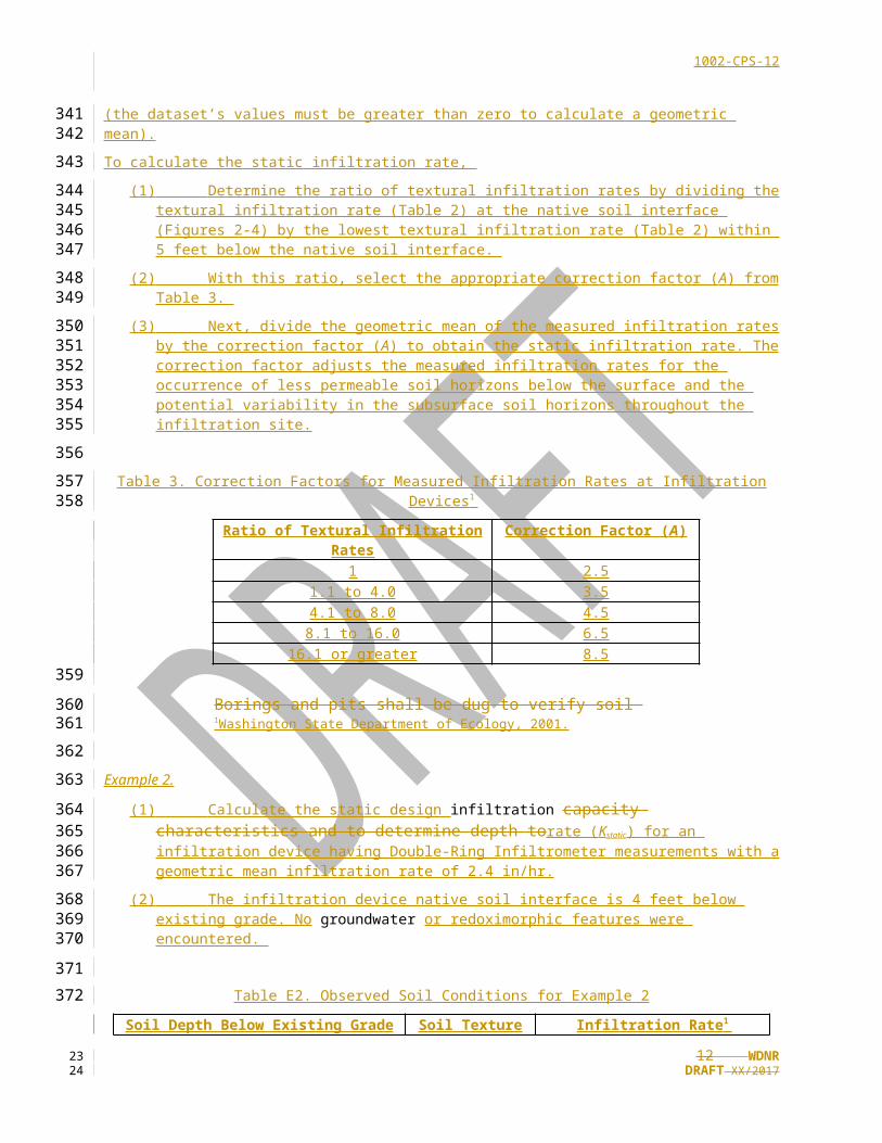
(1) Determine the ratio of textural infiltration rates by dividing the textural infiltration rate (Table 2) at the native soil interface (Figures 2-4) by the lowest textural infiltration rate (Table 2) within 5 feet below the native soil interface.
(2) With this ratio, select the appropriate correction factor (A) from Table 3.
(3) Next, divide the geometric mean of the measured infiltration rates by the correction factor (A) to obtain the static infiltration rate. The correction factor adjusts the measured infiltration rates for the occurrence of less permeable soil horizons below the surface and the potential variability in the subsurface soil horizons throughout the infiltration site.
Table 3. Correction Factors for Measured Infiltration Rates at Infiltration Devices1
Ratio of Textural Infiltration Rates Correction Factor (A)1 2.5
1.1 to 4.0 3.54.1 to 8.0 4.5
8.1 to 16.0 6.516.1 or greater 8.5
Borings and pits shall be dug to verify soil 1 Washington State Department of Ecology, 2001.
Example 2.
(1) Calculate the static design infiltration capacity characteristics and to determine depth torate (Kstatic) for an infiltration device having Double-Ring Infiltrometer measurements with a geometric mean infiltration rate of 2.4 in/hr.
(2) The infiltration device native soil interface is 4 feet below existing grade. No groundwater or redoximorphic features were encountered.
Table E2. Observed Soil Conditions for Example 2
Soil Depth Below Existing Grade (Inches) Soil Texture Infiltration Rate1 (Inches/Hour)0-12 Silt Loam 0.1312-84 Sandy Loam 0.50
84-180 Loam 0.241 Infiltration rates are from Table 2.
10 WDNRDRAFT XX/2017
268269270271272273
274
275276277
278
279280281282
283
284
285
286287
288
289
290291292
293294
295
296
297
298
299
1819
1002-CPS-11
Solution 2. (1) Calculate R, the ratio of textural infiltration rates = TN / TL
Where:
TN = Textural infiltration rate (Table 2, sandy loam) at the native soil interface
TL = Lowest textural infiltration rate (Table 2, loam) within 5 feet below the native soil interface
(2) R = 0.50 in/hr (sandy loam) / 0.24 in/hr (loam) = 2.1
(3) From Table 3, the correction factor (A) for 2.1 is 3.5.
(4) Calculate Kstatic, the static infiltration rate = G / A
Where:
G = the geometric mean of the measured infiltration rate = 2.4 in/hr
A = the correction factor from Table 3 based on R.
(5) K static = 2.4 in/hr / 3.5 = 0.69 in/hr
Infiltration Option 3 – Infiltration Rate Not Measured, Soil Compaction Not Mitigated
Notice: This section is not applicable where soil compaction mitigation actions will be implemented at an infiltration device (see Definitions).Mitigating soil compaction is important, as both topsoil and subsoils can become compacted during construction. It is best to avoid compacting areas, primarily during construction, in the first place, especially areas where infiltration devices will be located. However, construction of an infiltration device can lead to soil compaction, so appropriate actions should be taken to mitigate potential compaction. Soil compaction mitigation actions will vary based on the site and type of infiltration device. Individual infiltration design standards include actions to avoid and bedrock.mitigate soil compaction. Where actions are not taken to mitigate soil compaction, apply the correction factor (B) from Table 4 in this section to further reduce the design infiltration rate of the infiltration device.
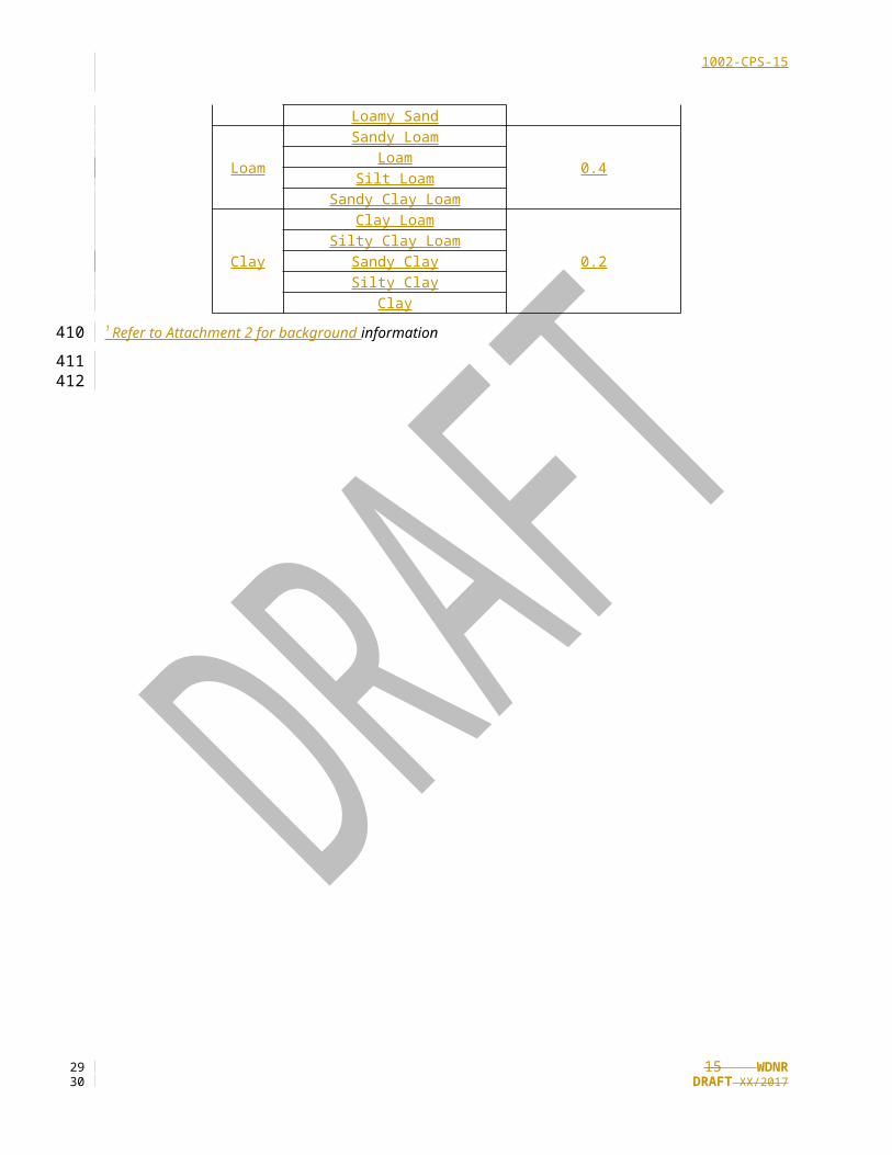
The following Table 4. Static Infiltration Rate1 Multiplier for Incidental Soil Compaction
Compacted Soil Type Correction Factor (B)
Sand
Coarse Sand or Coarser
0.9Loamy Coarse SandSand
Loamy Sand
Loam
Sandy Loam
0.4LoamSilt Loam
Sandy Clay Loam
Clay
Clay Loam
0.2Silty Clay Loam
Sandy ClaySilty Clay
Clay1 Refer to Attachment 2 for background information
11 WDNRDRAFT XX/2017
300
301
302
303
304305
306
307
308
309
310
311
312
313
314
315316
317318319320321322323324
325
326
327
328329
2021
1002-CPS-12
Example 3.(1) Calculate the static infiltration rate (Kstatic) where soil compaction mitigation is not performed.
Observations from the pit indicate that the soil texture with the lowest permeability within 5 feet below the native soil interface is sandy loam.
Solution 3:
(1) K static = TL * B
Where:
TL = Lowest textural infiltration rate (Table 2) within 5 feet below the native soil interface
B = the correction factor from Table 4
(2) = 0.5 in/hr (Table 2 with sandy loam) * 0.4 (Table 4 correction factor for sandy loam)
= 0.2 in/hr
Infiltration Option 4 – Infiltration Rate of Existing Vegetated Swales.
Notice: This section is only applicable to measuring infiltration rates at vegetated swales. The dynamic infiltration rate is used to model a flowing water condition, and shall be calculated for vegetated swales by multiplying the static infiltration rate by 0.5.Municipalities regulated under a municipal permit pursuant to subch. I of ch. NR 216, Wis. Adm. Code, may conduct infiltration rate testing of existing vegetated swale(s) as opposed to using infiltration rates based on soil texture that are developed from Table 2. Table 2 infiltration rates are static rates; model vegetated swales using a dynamic infiltration rate. A water quality model may be programmed to increase the effective infiltration rate within the model up to the full static rate when the swale slope is 0.5% or less.
Determine which vegetated swale sections qualify as water quality swales consistent with DNR’s Process to Assess and Model Grass Swales guidance. This guidance also modifies the ASTM D3385 Double-Ring Infiltrometer to a 2-hour test period. Refer to instructions under Infiltration Option 2, paragraphs 1 - 4, for the modified ASTM D3385 method and alternative infiltration testing methods.
Use either infiltration tests or hand-dug pits to assess the infiltration rate. If using infiltration tests, conduct at least five tests within the vegetated swale(s), equally spaced throughout the swale system to collect a representative dataset. Where an infiltration rate is too low to measure, a rate of 0.03 in/hr may be used to calculate a geometric mean of the dataset (the dataset’s values must be greater than zero to calculate a geometric mean).
If using hand-dug pits, dig one pit per 500 feet of swale, up to a maximum of 20 across the site, spatially distributed to capture site variation. For each pit, a State of Wisconsin Licensed Professional Soil Scientist must determine the static infiltration rate from Table 2 based on the soil texture of the least permeable soil horizon within 18 inches of the existing soil surface. See Consideration XX for potentially acceptable infiltration test methods.
The geometric mean of infiltration test or test pit results should be used. However, it may be appropriate to group certain test results where an infiltration trend is apparent and assign different geometric mean rates accordingly. Grouping of results may be done based on soil type or spatial reasons to provide representative results.
Apply a correction factor (C) based on the size of the dataset to the geometric mean of measured swale infiltration rates (Table 5). This correction factor accounts for the occurrence of less permeable soil horizons below the surface and the potential variability in the subsurface soil horizons throughout the water quality swale(s). A less permeable soil horizon below the location of the measurement increases the level of uncertainty in the measured value. Also, the uncertainty in a measurement is increased by the variability in the subsurface soil horizons throughout the proposed infiltration site. shall be recorded
Note that a larger data set will result in application of a lower correction factor to the geometric mean from the data set as shown in Table 5 below.
12 WDNRDRAFT XX/2017
330331332333
334
335
336
337
338
339
340
341
342
343344345
346347348349350
351352353354
355356357358359
360361362363364
365366367368
369370371372373374
375376
2223

1002-CPS-13
Table 5. Correction Factors for Measured Infiltration Rates in Water Quality Swales1
No. of Existing Swale Infiltration Tests Correction Factor (C)5-9 4
10-19 3≥20 2
1 Ahmed and Gulliver, 2010.
Example 4.
(1) Calculate the dynamic infiltration rate (Kdynamic) for 12 infiltration rate measurements that have a geometric mean infiltration rate (G) of 2.8 in/hr for a water quality swale system.
Solution 4. (1) K static = G / C
Where:
G = the geometric mean of the measured (static) infiltration rates
C = the correction factor from Table 5 based on the number of infiltration rate measurements taken
= 2.8 in/hr / 3
= 0.93 in/hr
(2) K dynamic = Kstatic * 0.5
= 0.93 in/hr * 0.5
= 0.46 in/hr
Step B:D – Soil and Site Evaluation Report
Include the site information required in Steps B and C in the Soil and Site Evaluation Report. Complete the single report prior to the construction plan submittal. Include the following in the report:
(1) The date or dates the datainformation was collected.
(2)[(1)] A legible site plan/map that is presented on paper that is no less than 8 ½ X 11 inches in size and:
[(a)] Is drawn to scale or fully dimensional.,
(a) Includes a site location map,
(b) Include a north arrow,
(c) Includes a permanent vertical and horizontal reference point,
(d) Illustrates the entire development site.,
[(b)] Shows all areas of planned filling and/or cutting. if known,
[a.] Includes a permanent vertical and horizontal reference point.[(c)] Shows the percent and direction of land slope for the site or contour lines. Highlight,
(e) Highlights areas with slopes over 20%.%,
13 WDNRDRAFT XX/2017
377
378
379380
381382
383
384
385
386
387388
389
390
391
392
393
394
395
396
397398399
400
401402
403404
405
406
407
408
409
410411
412
2425

1002-CPS-14
[(d)] Shows all flood plainfloodplain information (elevations and locations) that is pertinent to the site.,
[(e)] Shows the location locations of the soil pits,
(f) Shows the location by site grid and elevations of existing surface and bottom of all pits/borings included in the report.,
[(f)] LocationShows location of wetlands within the entire development site as field delineated and surveyed.,
[(g)] Location of karst features,Shows location of private wells within 100 feet of the development site, and public wells within 400 feet of the development site.,
[(h)] SoilShows location of karst features within 1,000 feet downgradient and 100 feet upgradient of the development site
Write soil profile descriptions must be written in accordance with the descriptive procedures, terminology and interpretations found in the Field Book for Describing and Sampling Soils, USDA, NRCS, 1998. Frozen (latest edition). Thaw frozen soil material must be thawed prior to conducting evaluations for soil color, texture, structure and consistency. In addition to the data determined in StepSteps B, soil profiles must and C, include the following information for each soil horizon or layer of the soil profiles:
[(1)] Thickness, in inches or decimal feet.
(1)[(2)] Munsell soil color notation.
(2)[(3)] Soil mottle or redoximorphic feature color, abundance, size and contrast.
(3)[(4)] USDA soil textural class with rock fragment modifiers.
(4)[(5)] Soil structure, grade size and shape.
(5)[(6)] Soil consistence, root abundance and size.
[(7)] Soil horizon boundary., distinctness and topography.
(6)[(8)] Occurrence of saturated soil, groundwater, bedrock or disturbed soil.
Step C. Evaluation of Specific Infiltration Areas
This step is to determine if locations identified for infiltration devices are suitable for infiltration, and to provide the required information to design the device.
A minimum number of borings or pits shall be constructed for each infiltration device (Table 1). The following information shall be recorded for Step C:
[1.] All the information under Step B.C.3.
[2.] A legible site plan/map that is presented on paper no less than 8 1/2 X 11 inches in size and:
[a.] Is drawn to scale or fully dimensional.[b.] Illustrates the location of the infiltration devices.
[c.] Shows the location of all pits and borings.[d.] Shows distance from device to wetlands.
[3.] An analysis of groundwater mounding potential is required as per Table 1. The altered groundwater level, based on mounding calculations, must be considered in determining the vertical separation
14 WDNRDRAFT XX/2017
413414
415
416417
418419
420421
422423424
425426427428429
430431
432
433
434
435
436
437
438
439440441442443444445446447448449450451452453454455456457458
2627
1002-CPS-15
distance from the infiltration surface to the highest anticipated groundwater elevation as specified in NR 151. References include but are not limited to Finnemore 1993 and 1995, and Hantush 1967.
[4.] One of the following methods shall be used to determine the design infiltration rate:
[a.] Infiltration Rate Not Measured - Table 2 shall be used if the infiltration rate is not measured. Select the design infiltration rate from Table 2 based on the least permeable soil horizon five feet below the bottom elevation of the infiltration system.
[b.] Measured Infiltration Rate - The tests shall be conducted at the proposed bottom elevation of the infiltration device. If the infiltration rate is measured with a Double-Ring Infiltrometer the requirements of ASTM D3385 shall be used for the field test.
[(1)] The measured infiltration rate shall be divided by a correction factor selected from Table 3. The correction factor adjusts the measured infiltration rates for the occurrence of less permeable soil horizons below the surface and the potential variability in the subsurface soil horizons throughout the infiltration site.
A less permeable soil horizon below the location of the measurement increases the level of uncertainty in the measured value. Also, the uncertainty in a measurement is increased by the variability in the subsurface soil horizons throughout the proposed infiltration site.
To select the correction factor from Table 3, the ratio of design infiltration rates must be determined for each place an infiltration measurement is taken. The design infiltration rates from Table 2 are used to calculate the ratio. To determine the ratio, the design infiltration rate for the surface textural classification is divided by the design infiltration rate for the least permeable soil horizon. For example, a device with a loamy sand at the surface and a least permeable layer of loam will have a design infiltration rate ratio of about 6.8 and a correction factor of 4.5. The depth of the least permeable soil horizon should be within five feet of the proposed bottom of the device or to the depth of a limiting layer.
[5.] To determine if infiltration is not required under NR 151.12(5)(c)6.a., a scientifically credible field test method is required unless the least permeable soil horizon five feet below the bottom of infiltration system is one of the following: sandy clay loam, clay loam, silty clay loam, sandy clay, silty clay, or clay. The infiltration rate used to claim the exemption shall be the actual field measurement and shall be used without the correction factors found in Table 3.
[(9)] Step D. Bedrock type, weather-fractured or unfractured, and elevation.
(7) Proposed native soil interface elevation.
(8) Seasonal and current groundwater elevations.
REQUIRED QUALIFICATIONS
Soil and Site Evaluation Report Contents
The site’s legal description and all information required in Steps B and C shall be included in the Soil and Site Evaluation Report. These reports Evaluations shall be completed prior to the construction plan submittal.by a Wisconsin Department of Safety and Professional Services Licensed Professional
Table 1: Evaluation Requirements Specific to Proposed Infiltration Devices
15 WDNRDRAFT XX/2017
459460461462463464465466467468469470471472473474475
476
477478479480481482483484485486487488489490491492493494495496
497
498
499
500
501502503504505506
507508
2829

1002-CPS-16
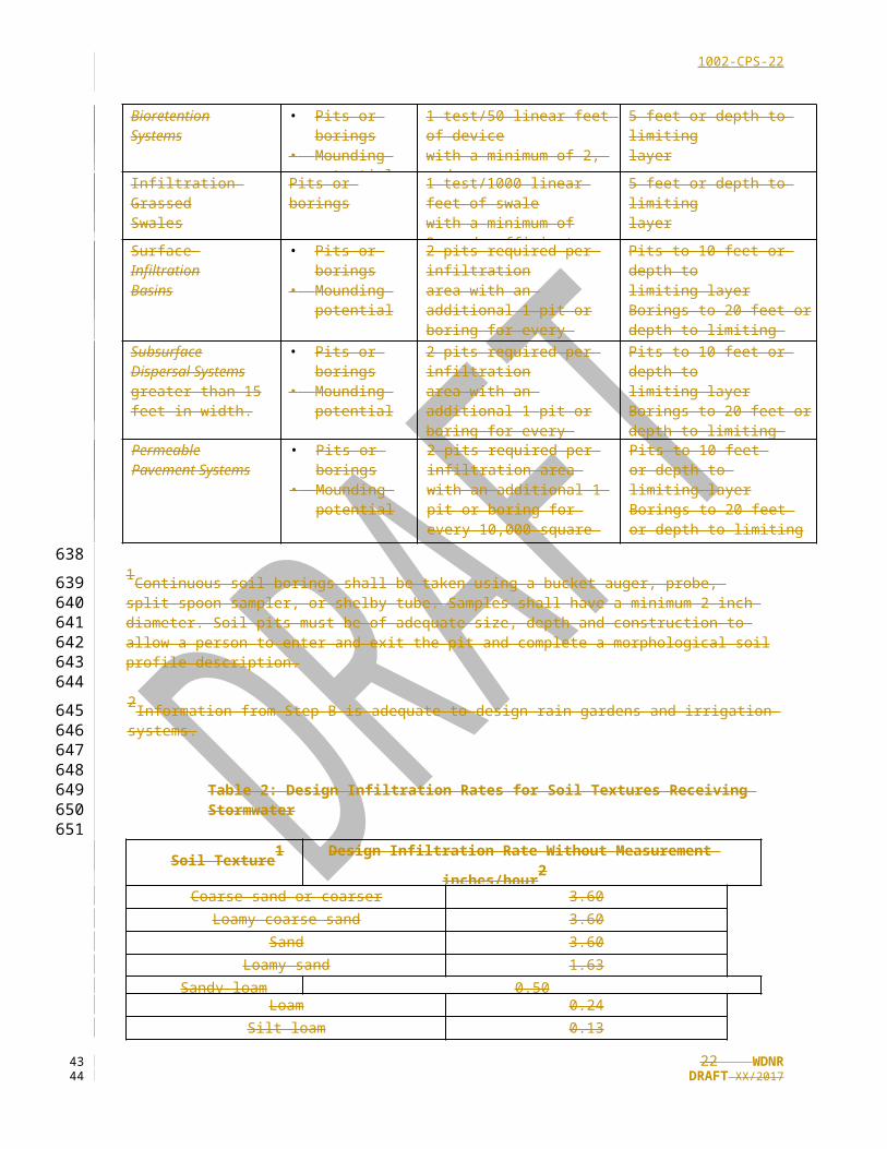
Infiltration Device Tests Required1
Minimum Number of Borings/Pits
Required
Minimum Drill/Test Depth Required Below
the Bottom of the Infiltration System
Irrigation Systems2 Pits or borings NA2 5 feet or depth to limiting layer,
Rain Garden2 Pits or Borings NA2 5 feet or depth to limiting layer,
InfiltrationTrenches(< 2000 sq feet impervious drainage area)
Pits or borings 1 test/100 linear feet of trenchwith a minimum of 2, andsufficient to determine variability
5 feet or depth to limitinglayer, whichever is less.
InfiltrationTrenches(> 2000 sq ft of impervious drainage area)
• Pits or borings• Mounding
potential
1 pit required and anadditional 1 pit or boring/100linear feet of trench, and sufficient to determine variability
Pits to 5 feet or depth tolimiting layerBorings to 15 feet or depth to limiting layer
BioretentionSystems
• Pits or borings• Mounding
potential
1 test/50 linear feet of devicewith a minimum of 2, andsufficient to determine variability
5 feet or depth to limitinglayer
Infiltration GrassedSwales
Pits or borings 1 test/1000 linear feet of swalewith a minimum of 2, and sufficient to
5 feet or depth to limitinglayer
Surface InfiltrationBasins
• Pits or borings• Mounding
potential
2 pits required per infiltrationarea with an additional 1 pit orboring for every 10,000 square feet of infiltration area, and sufficient to determine variability
Pits to 10 feet or depth tolimiting layerBorings to 20 feet or depth to limiting layer
SubsurfaceDispersal Systemsgreater than 15 feet in width.
• Pits or borings• Mounding
potential
2 pits required per infiltrationarea with an additional 1 pit orboring for every 10,000 square feet of infiltration area, and sufficient to determine variability
Pits to 10 feet or depth tolimiting layerBorings to 20 feet or depth to limiting layer
PermeablePavement Systems
• Pits or borings• Mounding
potential
2 pits required per infiltration area with an additional 1 pit or boring for every 10,000 square feet of infiltration area, and sufficient to determine variability
Pits to 10 feet or depth to limiting layerBorings to 20 feet or depth to limiting layer
1Continuous soil borings shall be taken using a bucket auger, probe, split-spoon sampler, or shelby tube. Samples shall have a minimum 2-inch diameter. Soil pits must be of adequate size, depth and construction to allow a person to enter and exit the pit and complete a morphological soil profile description.
2Information from Step B is adequate to design rain gardens and irrigation systems.
Table 2: Design Infiltration Rates for Soil Textures Receiving Stormwater
16 WDNRDRAFT XX/2017
509510511512513514515516517518
3031

1002-CPS-17
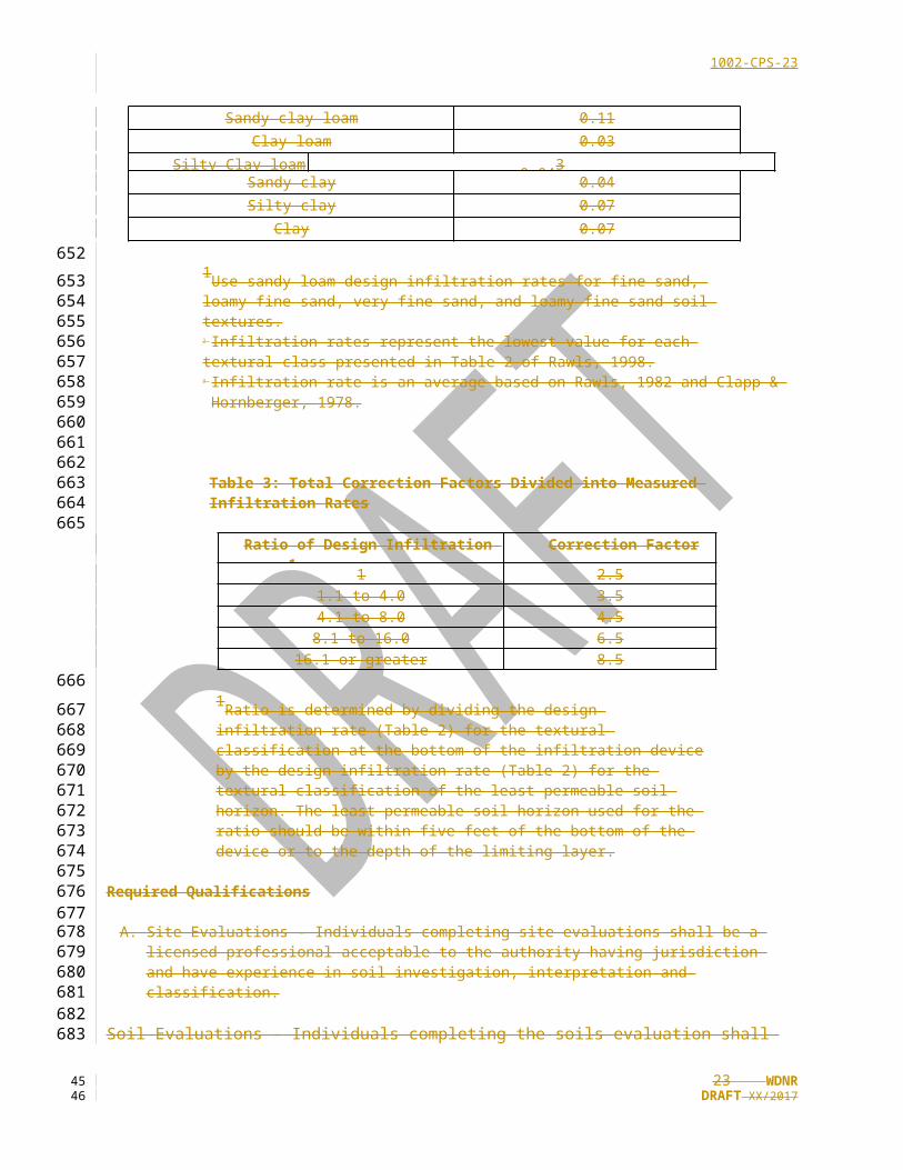
Soil Texture1 Design Infiltration Rate Without Measurement inches/hour2
Coarse sand or coarser 3.60Loamy coarse sand 3.60
Sand 3.60Loamy sand 1.63
Sandy loam 0.50Loam 0.24
Silt loam 0.13Sandy clay loam 0.11
Clay loam 0.03Silty Clay loam 0.043
Sandy clay 0.04Silty clay 0.07
Clay 0.07
1Use sandy loam design infiltration rates for fine sand, loamy fine sand, very fine sand, and loamy fine sand soil textures.[2] Infiltration rates represent the lowest value for each textural class presented in Table 2 of Rawls, 1998.[3] Infiltration rate is an average based on Rawls, 1982 and Clapp & Hornberger, 1978.
Table 3: Total Correction Factors Divided into Measured Infiltration Rates
Ratio of Design Infiltration Rates1 Correction Factor
1 2.51.1 to 4.0 3.54.1 to 8.0 4.5
8.1 to 16.0 6.516.1 or greater 8.5
1Ratio is determined by dividing the design infiltration rate (Table 2) for the textural classification at the bottom of the infiltration device by the design infiltration rate (Table 2) for the textural classification of the least permeable soil horizon. The least permeable soil horizon used for the ratio should be within five feet of the bottom of the device or to the depth of the limiting layer.
Required Qualifications
[A.] Site Evaluations - Individuals completing site evaluations shall be a licensed professional acceptable to the authority having jurisdiction and have experience in soil investigation, interpretation and classification.
Soil Evaluations - Individuals completing the soils evaluation shall be a Soil Scientist licensed by the Department of Regulation and Licensing or other licensed professional acceptable to the authority having jurisdiction., Licensed Professional Geologist, or Licensed Professional
17 WDNRDRAFT XX/2017
519
520521522523524525526527528529530
531532533534535536537538539540541542543544545546547
3233

1002-CPS-18
Hydrogeologist.
[VI.] Considerations
CONSIDERATIONS
Additional recommendations relating to design that may enhance the use of, or avoid problems with this practice but are not required to insure its function are as follows:
(1) The development site should be checked to determine the potential for archeological sites. This search may be conducted by state staff for projects required or funded by the state. If cultural or historical resources are known or suspected to be on site, contact the Wisconsin Historical Society.
(2) If a site is suspected of having contaminated soil or other materials from its prior land use, historic fill or other reason, then an evaluation to characterize the potential contamination may be warranted (an Environmental Site Assessment may be justified). New fill should be evaluated for contamination before it is brought to a new site. DNR guidance publications WA-1820 “Waste Soil Determinations and Identifying Clean Soil” (http://dnr.wi.gov/news/input/Guidance.html) and RR-060 “Management of Contaminated Soils and Other Solid Wastes” (http://dnr.wi.gov/files/PDF/pubs/rr/RR060.pdf) were developed to assist generators, regulators and property owners to manage waste properly.
(3) The permitting process requirements for development sites vary across the state and may also vary within a municipality depending on the number of lots being developed. The timing of Steps A, B, and C may need to be adjusted for the type of approval process. Be aware that any activity that will result in a discharge of fill material to a wetland will require a permit under s. 281.36 Wis. Stats. Wetlands are defined in s. 23.32 Wis. Stats and Ch. NR 103, Wis. Adm. Code.
(4) Resources available for completing Steps A and C:
(a) Sites listed in the Wisconsin Remediation and Redevelopment Database (WRRD), including GIS tool. http://dnr.wi.gov/topic/Brownfields/WRRD.html
(b) Floodplain areas as regulated under s. 87.30, Wis. Stats. and chs. NR 30, 31, and 116, Wis. Adm. Code.
(c) NRCS Climate Analysis for Wetlands Tables (WETS Tables). https://www.wcc.nrcs.usda.gov/climate/navigate_wets.html
(d) Endangered species habitat as shown on National Heritage Inventory County maps, http://dnr.wi.gov/topic/nhi.
(e) Access points and road setbacks as determined by county or municipal zoning plans.
Existing reports concerning the groundwater and bedrock. Examples include: Publications from USGS, NRCS, Regional Planning Commissions,
[(a)] WDNR, DATCP, WisDOT, UW system or WGNHS.
(f) The Drinking Water and Groundwater pages of the WDNR http://dnr.wi.gov/topic/DrinkingWater/
(g) The Wisconsin Grain Size Database http://wgnhs.uwex.edu/maps/data
(h) WDNR Surface Water Data Viewer http://dnr.wi.gov/topic/surfacewater/swdv/
(i) WDNR’s Process to Assess and Model Grass Swales guidance. Steps for “modified” Double Ring infiltrometer test are given within this guidance. http://dnr.wi.gov/topic/stormwater/standards/ms4_modeling.html
18 WDNRDRAFT XX/2017
548
549550551552553
554555
556557558559
560561562563564565566567
568569570571572
573574575576
577578
579580
581582
583
584585586
587588
589
590
591592593
3435

1002-CPS-19
(5) If a karst feature is located within the site, a Karst Inventory Forms from the Wisconsin Geological and Natural History Survey should be filled out (https://wgnhs.uwex.edu/water-environment/karst-sinkholes/ ) .
(6) Groundwater monitoring wells, constructed as per chapterch. NR 141, Wis. Adm. Code, can be used to determine the seasonal high groundwater level. Large sites considered for infiltration basins may need to be evaluated for the direction of groundwater flow.
(7) Consider conducting a groundwater mounding analysis to verify that the highest anticipated groundwater level does not approach the native soil interface. the infiltration rate into saturated soil in this case may be at or near zero. This standard requires that limiting layers within 5 feet below the native soil interface of an infiltration device be considered in the design infiltration rate. It is also possible for a limiting layer more than 5 feet below the native soil interface to affect an infiltration device where lateral movement is limited.. Increased mounding height, and therefore the potential for increased infiltration device drawdown time, are more likely to occur under the following conditions: shallow depth to groundwater or limiting layer, increased infiltration device size, decreased device length/width ratio, the presence of low-hydraulic conductivity material, thin aquifer thickness, and shallow water table gradient. It is also appropriate to conduct a mounding analysis in locations where mounding may impact basements or adjacent property. Refer to http://dnr.wi.gov/topic/stormwater/standards/gw_mounding.html for mounding calculation guidance.
Ch. [A.] Karst Inventory Forms on file with the Wisconsin Geological and Natural History Survey should
be filled out if a karst feature is located within the site.
[B.] Cation Exchange Capacity (CEC) of the soil can indicate the number of available adsorption sites. Sandy soils have limited adsorption capacity and a CEC ranging from 1-10 meq/100g. Clay and organic soils have a CEC greater than 20 and have a high adsorption rate.
[C.] Soil organic matter and pH can be used to determine adsorption of stormwater contaminants. A pH of 6.5 or greater is optimal. A soil organic content greater than 1 percent will enhance adsorption.
[(2)] NR 151 Wis. Adm. Code provides for a maximum area to be dedicated for infiltration depending upon land use. This cap can be voluntarily exceeded.
[(3)] One or more areas within a development site may be selected for infiltration. A development site with many areas suitable for infiltration is a good candidate for a dispersed approach to infiltration. It may be beneficial to contrast regional devices with onsite devices for sites that receive runoff from one lot or a single source area within a lot, such as rooftop or parking lot.
[(4)] StormwaterConsider conducting a soil investigation to a depth of 15 feet below the existing grade as standard protocol, unless bedrock or groundwater is reached, and deeper if this area will be ‘cut,’ or lowered, from existing grade
(8) In some situations, adding fill to a location to increase the separation distance between the proposed bottom of an infiltration device and a limiting layer may make a location suitable for infiltration.
(9) The authority having jurisdiction will decide if a proposed alternative infiltration test method is acceptable. It is best to discuss the proposed plan with the authority before detail design.
(10) The Modified Philip Dunne infiltration test is suitable for assessment of required maintenance because accumulation of fine particles limit the infiltration rate in these practices.
(11) Devices located on or near final slopes of ≥20%may be unstable. Consider a slope stability calculation.
19 WDNRDRAFT XX/2017
594595596
597598599
600601602603604605606607608609610611612
613614615616617618619620621622623624625
626627628629630
631632633634
635636637
638639
640641
642643
3637
1002-CPS-20
(12) No construction sediment should enter the infiltration device. This includes sediment from site grading as well as construction activities. If possible, delineate and protect from compaction areas selected for infiltration during grading and construction. This will help to preserve the infiltration rate and extend the life of the device.
(13) Class V injection wells are not addressed in this document.
(14) In projects which involve piping of storm water, consult plumbing code in ch. SPS 382 Wis. Adm. Code.
(15)Storm water infiltration devices may fail prematurely if there is:
[(a)] An inaccurate estimation of the Design Infiltration Rate;
(a)[(b)] An inaccurate estimation of the seasonal high water table or bedrock;
(b)[(c)] Excessive compacting or sediment loading during construction;
(c)[(d)] No pretreatment for post-development and lack of maintenance.
REFERENCES A. Ahmed F., and Gulliver J.S. (2010). Manual for the Modified Philip-Dunne (MPD) Infiltrometer. St.
No construction erosion should enter the infiltration device. This includes erosion from site grading as well as home building and construction. If possible, rope off areas selected for infiltration during grading and construction. This will preserve the infiltration rate and extend the life of the device.
[D.] Resources available for completing Step A. Initial screening:
[1.] Sites listed on the GIS Registry of Closed Remediation sites. http://gomapout.dnr.state.wi.us/org/at/et/geo/gwur/index.htm
[2.] Sites listed in the Bureau of Remediation and Redevelopment Tracking System. http://dnr.wi.gov/org/aw/rr/brrts/index.htm
Flood plain areas as regulated under s.Anthony Falls Laboratory (http://www/safl.umn.edu).
1. 87.30, Wis. Stats. and NR 116, NR 30 and NR 31, Wis. Adm. Code.[3.] Wetlands as defined in Ch. NR 103, Wis.Adm. Code.[4.] Endangered species habitat as shown on National Heritage Inventory County maps
[(e)] Access points and road setbacks as determined by county or municipal zoning plans.
[5.] Existing reports concerning the groundwater and bedrock. Examples include: Publications from USGS, NRCS, Regional Planning Commissions, DNR, DATCP, DOT, UW system or WGNHS.
[6.] The Drinking Water and Groundwater pages of the DNR http://dnr.wi.gov/org/water/dwg/[7.] The Wisconsin Grain Size Database http:\\www.geology.wisc.edu/~qlab/
[E.] The development site should be checked to determine the potential for archeological sites. This search may be conducted by state staff for projects required or funded by the state.
[F.] Slopes 20% or greater are inappropriate for some infiltration devices.
[G.] Expect to complete the preliminary design work (Criteria Step A through Step C) before the approval process (platting). Once required information is compiled, the initial design work for an infiltration device can begin.
[H.] The approval process requirements for development sites vary across the state and may also vary within a municipality depending on the number of lots being developed. The timing of Steps A, B, and C might have to be adjusted for the type of approval process. The following is an
20 WDNRDRAFT XX/2017
644645646647
648
649650
651
652653
654
655
656
657
658
659660661662663664665666667668669670
671672673674
675676677678679680681682683684685686687688689690691692
3839

1002-CPS-21
example of when the steps might be completed for a typical development site requiring a plat. The sequence in the example would comply with the criteria for timing of Steps A, B, and C.
Step A should be completed before the preliminary plat and Step B should be completed before the final plat, or CSM is approved. For regional infiltration devices, and for devices constructed on public right-of-ways, public land or jointly owned land, Step C should be completed before the final plat or final CSM approval.
It can be difficult to select the final location and drainage area for an infiltration device before the use of the lot is known. Sometimes it is more desirable to design an infiltration device for an individual lot after the lot is purchased. For this situation Step C would be completed after the final plat is approved. The information for Step C would be collected when the lot is purchased. To give future devices credit towards achieving the infiltration performance standard, the final plat would contain approximate sizing information for each device. Information from Step A and B would be used to determine the approximate sizing information.
[I.] The inner ring of the Double-Ring Infiltrometer should be at least 12 inches in diameter.
[J.] Section NR 151.12(5)(c)5., is included in the administrative code as a means to discourage infiltration of runoff from or into the listed areas, due to potential concerns of groundwater contamination. Although it is not illegal to infiltrate storm water in areas with the listed limitations, DNR will not give credit for this infiltration towards meeting the infiltration requirements of ss. NR 151.12(5)(c)1. or NR 151.12(5)(c)2. Runoff that is infiltrated must be in compliance with s. NR 151.12(5)(c)8., which requires minimizing infiltration of pollutants so that groundwater quality standards are maintained.
[VII.] References
Armstrong, D.E. and R.L. Llena, 1992. Project Report on Stormwater Infiltration: Potential for Pollutant Removal, Water Chemistry Program University of Wisconsin-Madison to the U.S. EPA.
ASTM D 3385 – 88, 1988. Standard Test Method for Infiltration Rate of Soils in Field Using Double-Ring Infiltrometers.
Ch. NR 30, Wis. Adm. Code
Ch. NR 31, Wis. Adm. CodeBachhuber, J., Bannerman, R.T., and Corsi, S., 2001. ETV Verification Protocol Stormwater Soure Area Treatment Technologies, NSF International, Ann Arbor, Michigan.
Bouwer, H., 1978. Groundwater Hydrology, McGraw-Hill Book Company.
Ch. NR 116, Wis. Adm. Code
Ch. NR 103, Wis. Adm. Code
Ch. NR 141, Wis. Adm. Code
Ch. NR 151, Wis. Adm. Code
Ch. NR 811, Wis. Adm. Code (line 71)
Ch. NR 812, Wis. Adm. Code (line 71)
Ch. NR 815, Wis. Adm. Code (line 552)
Ch. SPS 382, Wis. Adm. Code Design, Construction, Installation, Supervision, Maintenance and Inspection of Plumbing.
21 WDNRDRAFT XX/2017
693694695696697698699700701702703704705706707708709710711712713714715716717718719720721722723724725
726
727728729730731732733
734
735
736
737
738
739
740
741742
4041
1002-CPS-22
Clapp, R.W. and G.M., Hornberger. 1978. Empirical equations for some hydraulic properties. Water Resources Research 14:601-604.
Comm 83, Wis. Adm. Code
Comm 85, Wis. Adm. Code
Ferguson, B.K., 1994. StormwaterStorm water Infiltration, CRC Press Inc.
Freeze, R.A and J.A. Cherry, 1979. Groundwater, Prentice-Hall, Inc., 604 pgs.
Finnemore, E. J., 1993. Estimation of Ground-Water Mounding Beneath Septic Drain Fields. Groundwater, Vol. 31 No. 6, pp. 884-889.
Finnemore, E.J., 1995. A program to calculate Ground-Water Mound Heights. Groundwater, Vol. 33, No. 1.
Hantush, M. S., 1967. Growth and Decay of Groundwater-Mounds in Response to Uniform Percolation. Water Resources Research, Vol. 3, No. 1, pp. 227-234.
Lowndes, M., 2000. “Infiltration Basins and Trenches” The Wisconsin StormwaterStorm water Manual, G3691-3.
McHenry County Soil and Water Conservation District USDA Natural Resources Conservation Service, 1991. Additional Requirements for subdivision to be served by septic systems.
NR 141, Wis. Adm. Code NR 140, Wis. Adm. CodeRawls, W.J., D.L. Brakensiek and K.E. Saxton, 1982. Estimation of Soil Water Properties, Transactions of the American Society of Agricultural Engineers Vol. 25, No. 5 pp. 1316 –1320 and 1328.
Rawls, W.J., Gimenez, and Grossman, R., 1998. Use of Soil Texture, Bulk Density and Slope of Water Retention Curve to Predict Saturated Hydraulic Conductivity, ASAE, Vol. 41(2), pp. 983-988.
Tyler, J.E. and Converse, J.C., 1994. Soil Acceptance of onsite wastewater as affected by soil
morphology and wastewater quality. In: D. Sievers (ed.) On-site wastewater treatment. Proc. of the 8th
International Symposium on Individual and Small Community Sewage Systems. ASAE. St. Joseph, MI.
Tyler, J.E. and Kuns, L. Kramer, Designing with Soil: Development and Use of a Wastewater Hydraulic Linear and Infiltration Loading Rate Table, unpublished.
U.S. EPA, February, 2002. Onsite Wastewater Treatment Systems Manual, EPA/625/R-00/008.
Washington State Department of Ecology, 2001. StormwaterStorm Water Management Manual for Western Washington, Publication Numbers 99-11 through 99-15.
[VIII.] Definitions
Munsell Color (Firm), 2010. Munsell soil color charts: with genuine Munsell color chips. Grand Rapids, MI:Munsell Color.
22 WDNRDRAFT XX/2017
743744
745746747748749750
751752753754755
756757758
759760761
762763764
765766767768769770771
772773774
775776777778779780781782783784785786787
788789790791792
4243
1002-CPS-23
Schoeneberger, P.J., D.A. Wysocki, E.C. Benham, and Soil Survey Staff. 2012. Field book for describing and sampling soils, Version 3.0. Natural Resources Conservation Service, National Soil Survey Center, Lincoln, NE.
DEFINITIONS Aquiclude: A geological material through which zero water flow occurs.
Aquitard: Compacted layer of clay, silt or rock that attenuates water flow underground.
Bedrock: Bedrock is a consolidated rock, or weathered in place parent material larger than 2 mm in size and greater than 50 percent of the soil profile.
Bioretention systems (Table 1):: Bioretention is an infiltration device consisting of an excavated area that is back-filled with an engineered soil, covered with a mulch layer or erosion control mat and planted with a diversity of woody and herbaceous vegetation. Storm water directed to the device percolates through the mulch and engineered soil, where it is treated by a variety of physical, chemical and biological processes before infiltrating into the native soil and/or discharges through an underdrain.
Class V injection well: Any bored, drilled, or driven shaft, or dug hole that is deeper than its widest surface dimension, or an improved sinkhole, or a subsurface fluid distribution system. Any infiltration device that has a subsurface pipe distribution system is considered to be an injection well. See Chapter NR 815, Wis. Adm. Code and http://dnr.wi.gov/topic/Wells?UIW.html for compliance criteria.
Construction Plan (V.Step D):plan: A map and/or plan describing the built-out features of an individual lot.
Coarse sand (V.Step B.B.1):: Soil material that contains 25% or more very coarse and coarse sand, and <50% any other one grade of sand.
Design infiltration rate (II.3):: A velocity, (in/hr), based on soil structure and texture, at which precipitation or runoff enters and moves into or through soil. The design rate is used to size an infiltration device or system. Rates are selected to be minimal rates for the different types of soils. Selection of minimal rates will provide a robust design and maximize the longevity of the devicebased on soil texture or in-field infiltration rate measurements with appropriate correction factors. See also: static infiltration rate, dynamic infiltration rate.
Development site (I.1):: The entire area planned for development, irrespective of how much of the site is disturbed at any one time or intended land use. It can be one lot or multiple lots.
Direct conduits to groundwater: Wells, sinkholes, swallets, fractured bedrock at the surface, mine shafts, non-metallic mines, tile inlets discharging to groundwater, quarries, or depressional groundwater recharge areas over shallow fractured bedrock.
Double-ring infiltrometer (V.Step C.4.b):Ring Infiltrometer: A device that directly measures infiltration rates into a soil surface. The double-ring infiltrometerDouble-Ring Infiltrometer requires a fairly large pit excavated to depth of the proposed infiltration device and preparation of a soil surface representative of the bottom of the infiltration area.
Dynamic infiltration rate: The infiltration rate accounting for flowing water conditions (multiply static infiltration rate by 0.5).
Existing grade: Slope of the site prior to modification.
Geometric mean: The n root of the product of n values. For example, the geometric mean of 0.5, 0.65,
23 WDNRDRAFT XX/2017
793794795
796797
798
799
800801
802803804805806
807808809810811
812813
814815816
817818819820821822823
824825826
827828829830
831832833834
835836837
838
8394445

1002-CPS-24
and 0.71 inches/hour is: ❑√❑ = 3√0.23075 = 0.61338 inches/hr
High groundwater level (V.Step A.4):: The higher of either the elevation to which the soil is saturated as observed as a free water surface in an unlined hole, or the elevation to which the soil has been seasonally or periodically saturated as indicated by soil color patterns throughout the soil profile.
Highest anticipated groundwater elevation (V.Step C.3):level: The sum of the calculated mounding effects of the discharge and the seasonal high groundwater level.
Infiltration areas (V):: Areas within a development site that are suitable for installation of an infiltration device.
Infiltration basin (Table 1):: An open impoundment created either by excavation or embankment with a flat densely vegetated floor. It is situated on permeable soils and temporarily stores and allows a designed runoff volume to infiltrate the soil.
Infiltration device (II.2):: A structure or mechanism engineered to facilitate the entry and movement of precipitation or runoff into or through the soil. Examples of infiltration devices include irrigation systems, rain gardens, infiltration trenches, bioretention systems, infiltration grassed swales, infiltration basins, subsurface dispersal systems and infiltration trenches.
Infiltration trench (Table 1):: An excavated trench that is usually filled with coarse, granular material in which stormwaterstorm water runoff is collected for temporary storage and infiltration. Other materials such as metal pipes and plastic domes are used to maintain the integrity of the trench.
Irrigation system (Table 1): A system designed to disperse stored stormwater to lawns or other pervious areas.
Karst feature: An area or surficial geologic feature subject to bedrock dissolution so that it is likely to provide a conduit to groundwater, and may include caves, enlarged fractures, mine features, exposed bedrock surfaces, sinkholes, springs, seeps, or swallets.
Licensed Professional Soil Scientist: A soil scientist licensed by the Wisconsin Department of Safety and Professional Services.
Limiting layer (Table 1):: A limiting layer can be bedrock, an aquatard, aquacludeaquitard, aquiclude or the seasonal high groundwater table, but it does not include a perched water layer (water above an aquitard) or soil with redoximorphic features. A clayey soil aquitard may exist within a few feet below grade, but still have a suitable layer for infiltration within 5 feet below the proposed grade.
Native soil interface: The surface at which stormwater runoff is proposed to infiltrate. This surface is below an engineered soil layer (see Figures 2-4).
OSHA: Occupational Safety and Health Administration, a government agency to assure safe and healthy working conditions for working men and women (www.osha.gov).
Percent fines (V. Step B.B): the percentage of a : Percentage of given sample of soil, which passes through a # 200 sieve.
Perched conditions: A soil moisture regime where saturated soil (i.e., wet soil) is located above unsaturated soil (i.e., moist soil).
24 WDNRDRAFT XX/2017
840
841
842843844
845846847
848849850
851852853854
855856857858859
860861862863
864865866867868869870
871872
873874875876
877878879
880881
882883
884885886
4647

1002-CPS-25
Permeable pavement systems (Table 1):system: A pavement system that allows movement of stormwaterstorm water through the pavement surface and into a base/subbase reservoir designed to achieve water quality and quantity benefits.
Proposed grade: The proposed final design elevation and grade of the development. This is the top of topsoil, walkways, planting beds, roads, and parking areas.
Rain garden (Table 1):: A shallow, vegetated depression that captures stormwaterstorm water runoff and allows it to infiltrate.
Regional device (V.Step A):: An infiltration system that receives and stores stormwaterstorm water runoff from a large area.multiple structures. Infiltration basins are the most commonly used regional infiltration devices.
Redevelopment (V.Step A.6): Areas where new development is replacing older development.
Soil borings: For the purposes of this standard, soil borings are drilled, bored, cored or dug holes in the ground to obtain data from an unmixed soil sample, such as from a hollow stem auger or split spoon sampler. Mixed soil samples, such as those from a power auger, are not acceptable.
Soil compaction: An increase in bulk density of the soil. The more pressure per unit area exerted on soil, the greater the increase in bulk density, which leads to a decrease in infiltration. Also known as “soil structure degradation.”
Soil compaction mitigation: Taking action to decrease bulk density of the soil, which might be accomplished by a combination of mechanical, vegetative and/or chemical means. Example of compaction mitigation include: deep tilling, deep ripping, soil amendment and establishment of deep-rooted vegetation.
Soil parent material (V.Step A.3):: The unconsolidated material, mineral or organic, from which the solum develops.
Solum: The upper part of a soil profile, above the parent material, in which the processes of soil formation are active. The solum in mature soils includes the A and B horizons.
Static infiltration rate: Infiltration rate as measured for standing water.
Subsurface dispersal systems (Table 1):system: An exfiltration system that is designed to discharge stormwaterstorm water through piping below the ground surface, but above the seasonal high groundwater table. (subject to the applicable requirements of ch. NR 815, Wis Adm. Code).
Vegetated swale: A constructed stormwater conveyance system designed to achieve water quality and quantity benefits.
25 WDNRDRAFT XX/2017
887888889
890891892
893894
895896897898
899900901902903904
905906907
908909910911
912913
914915916
917
918919920
921922
923
924
4849
1002-CPS-26
Figure 1:
Site Evaluation for Infiltration Flow Chart of Steps
26 WDNRDRAFT XX/2017
925
926
927928
929
930
5051
1002-CPS-27
Figure 2:
Example Bioretention Basin Section
27 WDNRDRAFT XX/2017
Not to scale
931
932
933
934
935
5253

1002-CPS-28
Figure 3:
Example Bioretention Basin with Underdrain Section
28 WDNRDRAFT XX/2017
Not to scale
936
937
938
939
940
5455
1002-CPS-29
Figure 4:
Example Infiltration Basin Section
29 WDNRDRAFT XX/2017
Not to scale
941
942
943
944
5657

1002-CPS-30
Attachment 1:
30 WDNRDRAFT XX/2017
8
of
of
945946
5859
1002-CPS-31
31 WDNRDRAFT XX/2017
of
of
of
of
947
948
6061

1002-CPS-32
Attachment 2:Technical Note for Infiltration in Compacted Soils
The table below documents the approach used for developing multipliers for unmitigated incidental compaction in swales.
Soil Type
Infiltration Rate, inches/hour
Ratio(B/A)
Compaction Multiplier4
Table 2 Site Evaluation for
Infiltration 10021
(A)
Pitt Compaction Measurements2 or
Extrapolation3 (B)
Sand
Coarse Sand or Coarser 3.6 3.263 0.91
0.9Loamy Coarse Sand 3.6 3.263 0.91
Sand 3.6 3.263 0.91
Loamy Sand 1.63 1.467 0.90
Loam
Sandy Loam, fine sand, loamy sand, very fine sand, and loamy fine sand 0.5 0.223 0.44
0.4Loam 0.24 0.11 0.46
Silt Loam 0.13 0.0143 0.11
Sandy Clay Loam 0.11 0.0242 0.22
Clay
Clay Loam 0.03 0.00663 0.22
0.2
Silty Clay Loam 0.045 0.01 0.23
Sandy Clay 0.04 0.01 0.25
Silty Clay 0.07 0.002 0.03
Clay 0.07 <0.0023 0.03
1 Infiltration rates represent the lowest value for each textural class presented in Table 2 of Rawls, 1998.2 Compacted soils data from Table 8 (Standard Compaction) of Pitt, R., et al. 2003.3 Extrapolated number4 Multipliers were developed from a ratio of the compacted soil infiltration rates from the Pitt, R. et al. 2003 research and Table 2 Site Evaluation for Infiltration 1002 infiltration rates, then simplified into three categories.5 Infiltration rate in Table 2 Site Evaluation for Infiltration 1002 is an average based on Rawls 1982 and Clapp and Hornberger, 1978.
32 WDNRDRAFT XX/2017
949
950
951952
953
954
955
956957958
959960
961
6263