Embed Size (px)
Citation preview
energies
Article
Microwave Wireless Power Transfer System Based on aFrequency Reconfigurable Microstrip Patch Antenna Array
Haiyue Wang , Lianwen Deng , Heng Luo * , Junsa Du, Daohan Zhou and Shengxiang Huang
�����������������
Citation: Wang, H.; Deng, L.; Luo,
H.; Du, J.; Zhou, D.; Huang, S.
Microwave Wireless Power Transfer
System Based on a Frequency
Reconfigurable Microstrip Patch
Antenna Array. Energies 2021, 14, 415.
https://doi.org/10.3390/en14020415
Received: 26 November 2020
Accepted: 8 January 2021
Published: 13 January 2021
Publisher’s Note: MDPI stays neu-
tral with regard to jurisdictional clai-
ms in published maps and institutio-
nal affiliations.
Copyright: © 2021 by the authors. Li-
censee MDPI, Basel, Switzerland.
This article is an open access article
distributed under the terms and con-
ditions of the Creative Commons At-
tribution (CC BY) license (https://
creativecommons.org/licenses/by/
4.0/).
School of Physcis and Electronics, Central South University, Changsha 410083, China;[email protected] (H.W.); [email protected] (L.D.); [email protected] (J.D.);[email protected] (D.Z.); [email protected] (S.H.)* Correspondence: [email protected]; Tel.: +86-139-7585-1402
Abstract: The microwave wireless power transfer (MWPT) technology has found a variety of appli-cations in consumer electronics, medical implants and sensor networks. Here, instead of a magneticresonant coupling wireless power transfer (MRCWPT) system, a novel MWPT system based ona frequency reconfigurable (covering the S-band and C-band) microstrip patch antenna array isproposed for the first time. By switching the bias voltage-dependent capacitance value of the varactordiode between the larger main microstrip patch and the smaller side microstrip patch, the workingfrequency band of the MWPT system can be switched between the S-band and the C-band. Specifi-cally, the operated frequencies of the antenna array vary continuously within a wide range from 3.41to 3.96 GHz and 5.7 to 6.3 GHz. For the adjustable range of frequencies, the return loss of the antennaarray is less than −15 dB at the resonant frequency. The gain of the frequency reconfigurable antennaarray is above 6 dBi at different working frequencies. Simulation results verified by experimentalresults have shown that power transfer efficiency (PTE) of the MWPT system stays above 20% atdifferent frequencies. Also, when the antenna array works at the resonant frequency of 3.64 GHz, thePTE of the MWPT system is 25%, 20.5%, and 10.3% at the distances of 20 mm, 40 mm, and 80 mm,respectively. The MWPT system can be used to power the receiver at different frequencies, which hasgreat application prospects and market demand opportunities.
Keywords: microwave wireless power transfer; antenna array; power transfer efficiency; fre-quency reconfigurable
1. Introduction
The power supply technology used for various electronics is important, and the con-ventional power supply technology is provided by using cables, which can be hazardous,inconvenient, or impossible [1,2]. The transformation of charging technology from usingtraditional cables to wireless power transfer (WPT) is suitable for the booming developmentof portable devices, consumer electronics, robots, and other fields [3–5]. The WPT technol-ogy has attracted great attention due to its promising application potential in the field ofcharging [6,7]. One of the interesting and highly requested directions for wireless energytransfer is sensor applications [8,9]. There are many types of WPT technologies includingmagnetic resonant coupling, microwaves, inductive coupling, radio waves, lasers, and soforth [10,11]. Out of these, the microwave wireless power transfer (MWPT) technology cantransfer energy over relatively long distances with miniaturized antennas, which has greatmarket demand [12].
At present, the MWPT technology has been applied in various fields, such as electricvehicles and mobile phones powered by electromagnetic waves and the MWPT systemsinside buildings [13,14]. The microstrip patch antenna array has advantages of a simpleprocess, small volume, light weight, low profile, and easy integration, which is whyit is widely used in the field of WPT. A series of theoretical and experimental resultsabout MWPT systems with the microstrip patch antenna arrays were conducted [15]. Also,
Energies 2021, 14, 415. https://doi.org/10.3390/en14020415 https://www.mdpi.com/journal/energies
Energies 2021, 14, 415 2 of 12
many various methods have been employed to increase the power transfer efficiency (PTE),performances, and robustness of the MWPT systems by designing transmitting arrays [16–19].A MWPT system operating at the frequency of 5.8 GHz by using an 8 × 8 transmittingantenna array and a 4 × 4 receiving antenna array was presented, and the PTE of thesystem was 33.4% at the distance of 40 cm [20]. Additionally, in order to improve theefficiency of the system, an optimized MWPT system using an 8 × 8 transmitting patchantenna array and a 8 × 8 receiving patch antenna array at the frequency of 5.8 GHz andthe distance of 100 cm. The measured results show that the PTE of this MWPT systemis 46.9% [21]. However, for the above mentioned WPT systems, receivers only catch theenergy at a single frequency, regardless of their demands. This may cause malfunctionsand failures, and the PTE of the system may therefore be reduced.
In order to resolve this issue, many methods have been adopted in the magneticresonant coupling wireless power transfer (MRCWPT) system [22–25]. Frequency reconfig-urable MRCWPT systems were developed in previous works [22,23] by adding adaptivelyswitching resonant capacitances. In the reference [24], a new approach based on reconfig-urable magnetic resonant structures is proposed to achieve high energy efficiency and lowvolt-amp ratings. This basic principle is to create more than one efficiency-load curve. Bycombining a variable coupling technique, a frequency reconfigurable MRCWPT systemhas been proposed by varying the distance between the transmitter and the receiver [25].In addition, a shape-reconfigurable modularized MRCWPT system in [26] achieves shapereconfigurability by using different structures and positional combinations of resonantmodules. The reconfigurability in the reconfigurable MRCWPT system in [27] is achievedby adaptively switching between different sizes of drive loops and load loops. Here, in-stead of a MRCWPT system, a novel MWPT system based on a frequency reconfigurable(covering the S-band and C-band) microstrip patch antenna array is proposed for the firsttime to power the receiver at the different frequencies. This paper is organized as follows.The frequency reconfigurable microstrip patch antenna array is described in Section 2. InSection 3, the simulation and the measurement of the proposed frequency reconfigurableMWPT system are presented. The experimental results are compared with the simulationresults. Finally, Section 4 draws conclusions.
2. Frequency Reconfigurable Microstrip Patch Antenna Array2.1. The Configuration and Design of the Patch Antenna Array
A conventional antenna array only works at one frequency. This is because when theconventional antenna is used as the transmitter for wireless power transfer (WPT), theconventional antenna used as the receiver only receives the energy from the transmitter atthe same working frequency. Also, when the working frequency of the receiver changes, thepower transfer efficiency of the system will reduce. In addition to the conventional antennaonly being able to power the receiver at one working frequency, it cannot power the receiverfor different frequencies, regardless of energy demands. This may cause malfunctions andfailures, and the PTE of the system may decrease as a result. The frequency reconfigurableantenna continuously adjusts the working frequency within a certain frequency range.The WPT system based on a frequency reconfigurable antenna can power the receiversat different frequencies. It was shown that the PTE of the WPT system remains stable atdifferent frequencies. Also, the PTE of the system does not clearly decrease as the resonantfrequency of the receiver changes. Therefore, the frequency reconfigurable array moreimportant than the conventional antenna array for wireless power transfer.
The operating mechanism of the array is that the array radiates the electromagneticwave if four patches are excited. Under the excitation of the main mode, the directionof the electric field changes along the length of the half-wavelength patch. The antennaarray radiates energy mainly through the gap between the open edge of the patch and thefloor, and the electromagnetic wave radiated over the narrow seam can be equivalent tothe magnetic flux. According to the array antenna theory, the radiation field at the centerof two arrays is the largest, as the direction of patch normal, while the radiation field
Energies 2021, 14, 415 3 of 12
deviating from the corresponding direction with the normal direction becomes smaller. Theelectric field of the two radiated edges can be decomposed into the vertical and horizontalcomponents relative to the ground plane. The length of the radiation patch is set as a halfwavelength. According to the transmission line theory of half wavelengths, the verticalcomponents of the two radiation edge crevice decomposition cancel each other out in thefar field and generate no radiation, while the horizontal component has the same directionand produces the strongest radiation, meaning that the radiation field is the strongest inthe direction perpendicular to the antenna surface.
The frequency reconfigurable antenna array is fed by a coaxial feed. The feed networkof the antenna array uses the power divider. The power divider is designed to provide thesame excitation power. For a frequency tuning operation, varactor diodes are used. Thevaractor diode is placed between the larger main patch and the smaller side patch, whichhas the variable bias voltage provided by the adjustable DC power source. By changingthe capacitance of those varactors, the resonance frequency of the patch antenna array canbe tuned.
The antenna dimensions can be derived from the working frequency of the microstrippatch antenna. The variable symbol W represents the width of the patch, which can bederived as follows [28]:
W =c
2 f(
εr + 12
)− 1
2(1)
where the variable symbol c is the speed of light, and the variable symbol εr is the relativedielectric constant of the dielectric material. The dielectric material is epoxy resin, whilethe variable symbol f is the working frequency of the patch antenna. The thickness ofdielectric material is h. The metal layer is copper and the effective dielectric constant εe canbe derived as follows [29]:
εe =εr + 1
2+
εr − 12
(1 + 12h
W)− 1
2. (2)
The length of the radiation gap is ∆L and the length of the patch is L [30].
∆L = 0.412h(εe + 0.3)(W/h + 0.264)(εe − 0.258)(W/h + 0.8)
(3)
L =c
2 f√
εe− 2∆L (4)
The simulation model of the frequency reconfigurable microstrip patch antenna arrayis shown in Figure 1. The patch antenna array mainly consists of 4 main patches, 16 sidepatches and the feed network. By placing the varactor diode (SMV1281) inside the largermain patch and the smaller side patch, the antenna can perform as a frequency reconfig-urable antenna array. The SMV1281 varactor diode has an adequate range of capacitancevalues from 0.69 pF to 13.3 pF, and it has low series resistance. Adding 4 varactors on theside of the patch is used to changing the working frequency of the frequency reconfigurableantenna array. The feed network is used to feed the antenna array and the lumped port isused in the simulation software HFSS (High Frequency Structure Simulator) to excite thepatch antenna array.
Energies 2021, 14, 415 4 of 12Energies 2021, 14, x FOR PEER REVIEW 4 of 12
Unit: mml0=5
w0=2
M=1W=19L=16.75
Main Patch
FR4
Feed network
Side Patch Lumped Port
Variode
Variode
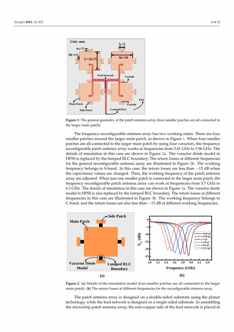
Figure 1. The general geometry of the patch antenna array (four smaller patches are all connected
to the larger main patch).
The frequency reconfigurable antenna array has two working states. There are four
smaller patches around the larger main patch, as shown in Figure 1. When four smaller
patches are all connected to the larger main patch by using four varactors, the frequency
reconfigurable patch antenna array works at frequencies from 3.41 GHz to 3.96 GHz. The
details of simulation in this case are shown in Figure 2a. The varactor diode model in
HFSS is replaced by the lumped RLC boundary. The return losses at different frequencies
for the general reconfigurable antenna array are illustrated in Figure 2b. The working
frequency belongs to S-band. In this case, the return losses are less than −15 dB when the
capacitance values are changed. Then, the working frequency of the patch antenna array
are adjusted. When just one smaller patch is connected to the larger main patch, the fre-
quency reconfigurable patch antenna array can work at frequencies from 5.7 GHz to 6.3
GHz. The details of simulation in this case are shown in Figure 3a. The varactor diode
model in HFSS is also replaced by the lumped RLC boundary. The return losses at dif-
ferent frequencies in this case are illustrated in Figure 3b. The working frequency belongs
to C-band, and the return losses are also less than −15 dB at different working frequen-
cies.
Side Patch
Main Patch
Lumped RLC
Boundary
3.0 3.2 3.4 3.6 3.8 4.0 4.2 4.4
-25
-20
-15
-10
-5
0
S1
1 (
dB
)
Frequency (GHz)
c=0.69 pf
c=0.89 pf
c=2 pf
c=4.8 pf
c=8.6 pf
c=13.3 pf
(a) (b)
Varactor Diode
Model
Figure 2. (a). Details of the simulation model (four smaller patches are all connected to the larger
main patch). (b). The return losses at different frequencies for the reconfigurable antenna array.
Figure 1. The general geometry of the patch antenna array (four smaller patches are all connected tothe larger main patch).
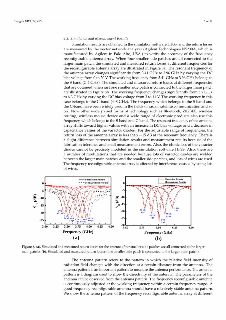
The frequency reconfigurable antenna array has two working states. There are foursmaller patches around the larger main patch, as shown in Figure 1. When four smallerpatches are all connected to the larger main patch by using four varactors, the frequencyreconfigurable patch antenna array works at frequencies from 3.41 GHz to 3.96 GHz. Thedetails of simulation in this case are shown in Figure 2a. The varactor diode model inHFSS is replaced by the lumped RLC boundary. The return losses at different frequenciesfor the general reconfigurable antenna array are illustrated in Figure 2b. The workingfrequency belongs to S-band. In this case, the return losses are less than −15 dB whenthe capacitance values are changed. Then, the working frequency of the patch antennaarray are adjusted. When just one smaller patch is connected to the larger main patch, thefrequency reconfigurable patch antenna array can work at frequencies from 5.7 GHz to6.3 GHz. The details of simulation in this case are shown in Figure 3a. The varactor diodemodel in HFSS is also replaced by the lumped RLC boundary. The return losses at differentfrequencies in this case are illustrated in Figure 3b. The working frequency belongs toC-band, and the return losses are also less than −15 dB at different working frequencies.
Energies 2021, 14, x FOR PEER REVIEW 4 of 12
Unit: mml0=5
w0=2
M=1W=19L=16.75
Main Patch
FR4
Feed network
Side Patch Lumped Port
Variode
Variode
Figure 1. The general geometry of the patch antenna array (four smaller patches are all connected
to the larger main patch).
The frequency reconfigurable antenna array has two working states. There are four
smaller patches around the larger main patch, as shown in Figure 1. When four smaller
patches are all connected to the larger main patch by using four varactors, the frequency
reconfigurable patch antenna array works at frequencies from 3.41 GHz to 3.96 GHz. The
details of simulation in this case are shown in Figure 2a. The varactor diode model in
HFSS is replaced by the lumped RLC boundary. The return losses at different frequencies
for the general reconfigurable antenna array are illustrated in Figure 2b. The working
frequency belongs to S-band. In this case, the return losses are less than −15 dB when the
capacitance values are changed. Then, the working frequency of the patch antenna array
are adjusted. When just one smaller patch is connected to the larger main patch, the fre-
quency reconfigurable patch antenna array can work at frequencies from 5.7 GHz to 6.3
GHz. The details of simulation in this case are shown in Figure 3a. The varactor diode
model in HFSS is also replaced by the lumped RLC boundary. The return losses at dif-
ferent frequencies in this case are illustrated in Figure 3b. The working frequency belongs
to C-band, and the return losses are also less than −15 dB at different working frequen-
cies.
Side Patch
Main Patch
Lumped RLC
Boundary
3.0 3.2 3.4 3.6 3.8 4.0 4.2 4.4
-25
-20
-15
-10
-5
0
S1
1 (
dB
)
Frequency (GHz)
c=0.69 pf
c=0.89 pf
c=2 pf
c=4.8 pf
c=8.6 pf
c=13.3 pf
(a) (b)
Varactor Diode
Model
Figure 2. (a). Details of the simulation model (four smaller patches are all connected to the larger
main patch). (b). The return losses at different frequencies for the reconfigurable antenna array. Figure 2. (a) Details of the simulation model (four smaller patches are all connected to the largermain patch). (b) The return losses at different frequencies for the reconfigurable antenna array.
The patch antenna array is designed on a double-sided substrate using the planartechnology, while the feed network is designed on a single-sided substrate. In assemblingthe microstrip patch antenna array, the non-copper side of the feed network is placed in

Energies 2021, 14, 415 5 of 12
direct contact with the ground of the patch antenna array, as shown in Figure 4a. This leadsto a low profile and compact structure. The dimensions of the frequency reconfigurablepatch antenna array in Figures 1 and 4a are listed in Table 1. The fabricated patch antennaarray is shown in Figure 4b,c for measurement. The SMA (SubMiniature Version A)connector is fed to the feed-line through the substrate material and the ground plane. Thereconfigurable antenna array and the SMA connector are designed on the FR4 substrates,which have a dielectric constant of 4.4 and a loss tangent of 0.02.
Energies 2021, 14, x FOR PEER REVIEW 5 of 12
Main Patch
Side Patch
Lumped RLC
Boundary
5.50 5.75 6.00 6.25 6.50-35
-30
-25
-20
-15
-10
-5
0
S1
1 (
dB
)
Frequency (GHz)
C=1 pf
C=1.5 pf
C=2 pf
C=3 pf
C=4 pf
(a) (b)
Varactor Diode
Model
Figure 3. (a). Details of the simulation model (one smaller patch is connected to the larger main patch). (b). The return
losses at different frequencies.
The patch antenna array is designed on a double-sided substrate using the planar
technology, while the feed network is designed on a single-sided substrate. In assembling
the microstrip patch antenna array, the non-copper side of the feed network is placed in
direct contact with the ground of the patch antenna array, as shown in Figure 4a. This
leads to a low profile and compact structure. The dimensions of the frequency reconfig-
urable patch antenna array in Figures 1 and 4a are listed in Table 1. The fabricated patch
antenna array is shown in Figure 4b,c for measurement. The SMA (SubMiniature Version
A) connector is fed to the feed-line through the substrate material and the ground plane.
The reconfigurable antenna array and the SMA connector are designed on the FR4 sub-
strates, which have a dielectric constant of 4.4 and a loss tangent of 0.02.
h1
h
Substrate of Patch Substrate of feed network
Patch
Grand of Patch Antenna Feed Network
(a) (b)
SMA
(c)
Figure 4. (a). Assembly schematic of antenna. (b) Top and (c) bottom views of the fabricated antenna.
Table 1. Dimensions of the antenna array.
Parameters Values
W 19.0 mm
L 16.8 mm
w0 2.0 mm
l0 5.0 mm
M 1.0 mm
h 0.8 mm
h1 1.6 mm
Figure 3. (a). Details of the simulation model (one smaller patch is connected to the larger main patch). (b). The returnlosses at different frequencies.
Energies 2021, 14, x FOR PEER REVIEW 5 of 12
Main Patch
Side Patch
Lumped RLC
Boundary
5.50 5.75 6.00 6.25 6.50-35
-30
-25
-20
-15
-10
-5
0
S1
1 (
dB
)
Frequency (GHz)
C=1 pf
C=1.5 pf
C=2 pf
C=3 pf
C=4 pf
(a) (b)
Varactor Diode
Model
Figure 3. (a). Details of the simulation model (one smaller patch is connected to the larger main patch). (b). The return
losses at different frequencies.
The patch antenna array is designed on a double-sided substrate using the planar
technology, while the feed network is designed on a single-sided substrate. In assembling
the microstrip patch antenna array, the non-copper side of the feed network is placed in
direct contact with the ground of the patch antenna array, as shown in Figure 4a. This
leads to a low profile and compact structure. The dimensions of the frequency reconfig-
urable patch antenna array in Figures 1 and 4a are listed in Table 1. The fabricated patch
antenna array is shown in Figure 4b,c for measurement. The SMA (SubMiniature Version
A) connector is fed to the feed-line through the substrate material and the ground plane.
The reconfigurable antenna array and the SMA connector are designed on the FR4 sub-
strates, which have a dielectric constant of 4.4 and a loss tangent of 0.02.
h1
h
Substrate of Patch Substrate of feed network
Patch
Grand of Patch Antenna Feed Network
(a) (b)
SMA
(c)
Figure 4. (a). Assembly schematic of antenna. (b) Top and (c) bottom views of the fabricated antenna.
Table 1. Dimensions of the antenna array.
Parameters Values
W 19.0 mm
L 16.8 mm
w0 2.0 mm
l0 5.0 mm
M 1.0 mm
h 0.8 mm
h1 1.6 mm
Figure 4. (a). Assembly schematic of antenna. (b) Top and (c) bottom views of the fabricated antenna.
Table 1. Dimensions of the antenna array.
Parameters Values
W 19.0 mmL 16.8 mm
w0 2.0 mml0 5.0 mmM 1.0 mmh 0.8 mmh1 1.6 mm
Energies 2021, 14, 415 6 of 12
2.2. Simulation and Measurement Results
Simulation results are obtained in the simulation software HFSS, and the return lossesare measured by the vector network analyzer (Agilent Technologies N5230A, which ismanufactured by Agilent in Palo Alto, USA.) to verify the accuracy of the frequencyreconfigurable antenna array. When four smaller side patches are all connected to thelarger main patch, the simulated and measured return losses at different frequencies forthe reconfigurable antenna array are illustrated in Figure 5a. The resonant frequency ofthe antenna array changes significantly from 3.41 GHz to 3.96 GHz by varying the DCbias voltage from 0 to 20 V. The working frequency from 3.41 GHz to 3.96 GHz belongs tothe S-band (2–4 GHz). The simulated and measured return losses at different frequenciesthat are obtained when just one smaller side patch is connected to the larger main patchare illustrated in Figure 5b. The working frequency changes significantly from 5.7 GHzto 6.3 GHz by varying the DC bias voltage from 3 to 11 V. The working frequency in thiscase belongs to the C-band (4–8 GHz). The frequency which belongs to the S-band andthe C-band have been widely used in the fields of radar, satellite communication and soon. Now other widely used forms of technology such as Bluetooth, ZIGBEE, wirelessrouting, wireless mouse device and a wide range of electronic products also use thisfrequency, which belongs to the S-band and C-band. The resonant frequency of the antennaarray shifts toward higher values with an increase in DC bias voltages and a decrease incapacitance values of the varactor diodes. For the adjustable range of frequencies, thereturn loss of the antenna array is less than −15 dB at the resonant frequency. There isa slight difference between simulation results and measurement results because of thefabrication tolerance and small measurement errors. Also, the ohmic loss of the varactordiodes cannot be precisely modeled in the simulation software HFSS. Also, there area number of modulations that are needed because lots of varactor diodes are weldedbetween the larger main patches and the smaller side patches, and lots of wires are used.The frequency reconfigurable antenna array is affected by interference caused by using lotsof wires.
Energies 2021, 14, x FOR PEER REVIEW 6 of 12
2.2. Simulation and Measurement Results
Simulation results are obtained in the simulation software HFSS, and the return
losses are measured by the vector network analyzer (Agilent Technologies N5230A,
which is manufactured by Agilent in Palo Alto, USA.) to verify the accuracy of the
frequency reconfigurable antenna array. When four smaller side patches are all con-
nected to the larger main patch, the simulated and measured return losses at different
frequencies for the reconfigurable antenna array are illustrated in Figure 5a. The resonant
frequency of the antenna array changes significantly from 3.41 GHz to 3.96 GHz by var-
ying the DC bias voltage from 0 to 20 V. The working frequency from 3.41 GHz to 3.96
GHz belongs to the S-band (2–4 GHz). The simulated and measured return losses at dif-
ferent frequencies that are obtained when just one smaller side patch is connected to the
larger main patch are illustrated in Figure 5b. The working frequency changes signifi-
cantly from 5.7 GHz to 6.3 GHz by varying the DC bias voltage from 3 to 11 V. The
working frequency in this case belongs to the C-band (4–8 GHz). The frequency which
belongs to the S-band and the C-band have been widely used in the fields of radar, satel-
lite communication and so on. Now other widely used forms of technology such as
Bluetooth, ZIGBEE, wireless routing, wireless mouse device and a wide range of elec-
tronic products also use this frequency, which belongs to the S-band and C-band. The
resonant frequency of the antenna array shifts toward higher values with an increase in
DC bias voltages and a decrease in capacitance values of the varactor diodes. For the
adjustable range of frequencies, the return loss of the antenna array is less than −15 dB at
the resonant frequency. There is a slight difference between simulation results and
measurement results because of the fabrication tolerance and small measurement errors.
Also, the ohmic loss of the varactor diodes cannot be precisely modeled in the simulation
software HFSS. Also, there are a number of modulations that are needed because lots of
varactor diodes are welded between the larger main patches and the smaller side patch-
es, and lots of wires are used. The frequency reconfigurable antenna array is affected by
interference caused by using lots of wires.
3.00 3.25 3.50 3.75 4.00 4.25 4.50
-25
-20
-15
-10
-5
0
S1
1 (
dB
)
Frequency (GHz)
Simulation Results
Measurement Results
0 V&
13.3 pF
1 V&
8.6 pF 20 V&
0.69 pF13 V&
0.89 pF
6 V&
2 pF
3 V&
4.8 pF
11 V&
1 pF
7.5 V&
1.5 pF
6 V&
2 pF
4.7 V&
3 pF
3.2 V&
4 pF
5.50 5.75 6.00 6.25 6.50-30
-25
-20
-15
-10
-5
0
S1
1 (
dB
)
Frequency (GHz)
Simulation Results
Measurement Results
(a) (b)
Figure 5. (a). Simulated and measured return losses for the antenna (four smaller side patches are all connected to the
larger main patch). (b). Simulated and measured return losses (one smaller side patch is connected to the larger main
patch).
The antenna pattern refers to the pattern in which the relative field intensity of ra-
diation field changes with the direction at a certain distance from the antenna. The an-
tenna pattern is an important pattern to measure the antenna performance. The antenna
pattern is a diagram used to show the directivity of the antenna. The parameters of the
antenna can be observed from the antenna pattern. The frequency reconfigurable antenna
Figure 5. (a). Simulated and measured return losses for the antenna (four smaller side patches are all connected to the largermain patch). (b). Simulated and measured return losses (one smaller side patch is connected to the larger main patch).
The antenna pattern refers to the pattern in which the relative field intensity ofradiation field changes with the direction at a certain distance from the antenna. Theantenna pattern is an important pattern to measure the antenna performance. The antennapattern is a diagram used to show the directivity of the antenna. The parameters of theantenna can be observed from the antenna pattern. The frequency reconfigurable antennais continuously adjusted at the working frequency within a certain frequency range. Agood frequency reconfigurable antenna should have a relatively stable antenna pattern.We show the antenna pattern of the frequency reconfigurable antenna array at different

Energies 2021, 14, 415 7 of 12
frequencies. This pattern indicates that the frequency reconfigurable antenna array worksnormally at different working frequencies. As a result, the antenna is very important forthe wireless power transfer system. The radiation gain patterns of the antenna array in thexz plane and yz plane at different frequencies are shown in Figure 6. The xz plane meansthat Phi is 0 deg, and the yz plane means phi is 90 deg. Radiation gain patterns maintainsimilar shapes at different states. In summary, with 16 varactors, this array can operatewith the maximum gain varying from 7.87 to 7 dBi when the operating frequency is tunedfrom 3.96 to 6.21 GHz.
Energies 2021, 14, x FOR PEER REVIEW 7 of 12
is continuously adjusted at the working frequency within a certain frequency range. A
good frequency reconfigurable antenna should have a relatively stable antenna pattern.
We show the antenna pattern of the frequency reconfigurable antenna array at different
frequencies. This pattern indicates that the frequency reconfigurable antenna array works
normally at different working frequencies. As a result, the antenna is very important for
the wireless power transfer system. The radiation gain patterns of the antenna array in
the xz plane and yz plane at different frequencies are shown in Figure 6. The xz plane
means that Phi is 0 deg, and the yz plane means phi is 90 deg. Radiation gain patterns
maintain similar shapes at different states. In summary, with 16 varactors, this array can
operate with the maximum gain varying from 7.87 to 7 dBi when the operating frequency
is tuned from 3.96 to 6.21 GHz.
(a) 3.41 GHz (b) 3.53 GHz (c) 3.64 GHz
(d) 3.75 GHz (e) 3.85 GHz (f) 3.96 GHz
-20
-10
0
100
60
120
180
240
300
-20
-10
0
10
Phi=0 deg
Phi=90 deg
7.87 dBi
-20
-10
0
100
60
120
180
240
300
-20
-10
0
10
Phi=0 deg
Phi=90 deg
7.76 dBi
-20
-10
0
100
60
120
180
240
300
-20
-10
0
10
Phi=0 deg
Phi=90 deg
7.64 dBi
-20
-10
0
100
60
120
180
240
300
-20
-10
0
10
Phi=0 deg
Phi=90 deg
7.5 dBi
-20
-10
0
100
60
120
180
240
300
-20
-10
0
10
Phi=0 deg
Phi=90 deg
7.2 dBi
-20
-10
0
100
60
120
180
240
300
-20
-10
0
10
Phi=0 deg
Phi=90 deg
7 dBi
-20
-10
0
100
60
120
180
240
300
-20
-10
0
10
Phi=0 deg
Phi=90 deg
7.32 dBi
(g) 5.79 GHz (h) 6.01 GHz (i) 6.21 GHz
-20
-10
0
100
60
120
180
240
300
-20
-10
0
10
7.61 dBi
Phi=0 Deg
Phi=90 Deg
-20
-10
0
100
60
120
180
240
300
-20
-10
0
10
7.82 dBi
Phi=0 Deg
Phi=90 Deg
Figure 6. Radiation gain patterns of the antenna array in the xz plane and yz plane at different frequencies.
The gain of the single patch antenna and the gain of the patch antenna array without
any smaller side patches are simulated. The gains of the single patch antenna and the
patch antenna array are shown in Figure 7. The gain of the single patch antenna is 4.4 dBi.
Also, the gain of the single patch antenna array is 7.8 dBi. Therefore, the gain is improved
by using the array. As a result, we updated the gains of the frequency reconfigurable
antenna array.
The gains of the antenna array at different frequencies between the S-band are
shown in Figure 8a. Also, the simulated and measured gains are illustrated in Figure 8b
when one smaller side patch is connected to the larger main patch. Simulated results
have shown that the gain is above 7 dBi. Measurement results have shown that the gain
of the antenna array is above 6 dBi at different frequencies. There was an error rate of
Figure 6. Radiation gain patterns of the antenna array in the xz plane and yz plane at different frequencies.
The gain of the single patch antenna and the gain of the patch antenna array withoutany smaller side patches are simulated. The gains of the single patch antenna and thepatch antenna array are shown in Figure 7. The gain of the single patch antenna is 4.4 dBi.Also, the gain of the single patch antenna array is 7.8 dBi. Therefore, the gain is improvedby using the array. As a result, we updated the gains of the frequency reconfigurableantenna array.
Energies 2021, 14, 415 8 of 12
Energies 2021, 14, x FOR PEER REVIEW 8 of 12
about 6% between the simulation results and the measurement results. Measured gains
were slightly lower than the simulated gains due to measurement errors and the fabrica-
tion tolerance. In short, the gains of the antenna array are relatively stable within the
range of the frequency. The gains of the frequency reconfigurable antenna array are
slightly lower than the gains of the patch antenna array without any smaller side patches.
Also, these gains are reduced as the capacitance of the varactor increases due to increases
in internal resistance. In short, the radiation patterns and the gains of the antenna array
are relatively stable within the range of the frequency.
Figure 7. The gains of the single patch antenna and the patch antenna array.
(a) (b)
5.8 6.0 6.20
2
4
6
8
10
Simulation Results
Measurement Results
Error
Frequency (GHz)
Ga
in (
dB
i)
0
10
20
30
40
50
60
70
80
90
100
Erro
r (%)
3.4 3.5 3.6 3.7 3.8 3.9 4.00
2
4
6
8
10 Simulation Results
Measurement Results
Error
Frequency (GHz)
Gain
(d
Bi)
0
10
20
30
40
50
60
70
80
90
100
Erro
r (%)
Figure 8. (a). Simulated and measured gains of the antenna (four smaller side patches are all connected to the larger main
patch). (b). Simulated and measured gains (one smaller side patch is connected to the larger main patch).
3. The Microwave Wireless Power Transfer System
The simulation model of the MWPT system can be built by using the simulation
software HFSS. The model of the proposed MWPT system is shown in Figure 9a. The
frequency reconfigurable antenna array is used as the transmitter of the MWPT system to
transmit energy. The antenna is also used as the receiver of the MWPT system to receive
energy. The capacitance value of the varactor diode changes with different voltage,
which has been shown in Figure 9a. This suggests that the frequency reconfigurable an-
tenna array can work at the continuous switchable resonant frequency within a certain
range. The energy is transmitted from the transmitter to the receiver through the elec-
tromagnetic field at the different working state, as shown in Figure 9a. The variable
symbol d is the distance between the transmitter and the receiver.
The experimental platform for the MWPT system is illustrated in Figure 9b. The
transmitter and the receiver are connected to port 1 and port 2 of the vector network an-
-160 -120 -80 -40 0 40 80 120 160-20
-15
-10
-5
0
5
107.8 dBi
Gain
(d
Bi)
Theta (Deg)
patch, Phi=0 deg
patch, Phi=90 deg
array, Phi=0 deg
array, Phi=90 deg
4.4 dBi
Figure 7. The gains of the single patch antenna and the patch antenna array.
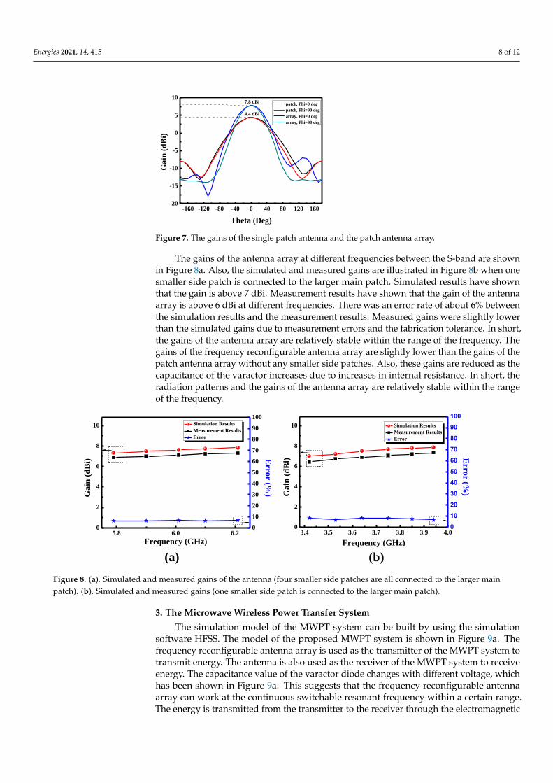
The gains of the antenna array at different frequencies between the S-band are shownin Figure 8a. Also, the simulated and measured gains are illustrated in Figure 8b when onesmaller side patch is connected to the larger main patch. Simulated results have shownthat the gain is above 7 dBi. Measurement results have shown that the gain of the antennaarray is above 6 dBi at different frequencies. There was an error rate of about 6% betweenthe simulation results and the measurement results. Measured gains were slightly lowerthan the simulated gains due to measurement errors and the fabrication tolerance. In short,the gains of the antenna array are relatively stable within the range of the frequency. Thegains of the frequency reconfigurable antenna array are slightly lower than the gains of thepatch antenna array without any smaller side patches. Also, these gains are reduced as thecapacitance of the varactor increases due to increases in internal resistance. In short, theradiation patterns and the gains of the antenna array are relatively stable within the rangeof the frequency.
Energies 2021, 14, x FOR PEER REVIEW 8 of 12
about 6% between the simulation results and the measurement results. Measured gains
were slightly lower than the simulated gains due to measurement errors and the fabrica-
tion tolerance. In short, the gains of the antenna array are relatively stable within the
range of the frequency. The gains of the frequency reconfigurable antenna array are
slightly lower than the gains of the patch antenna array without any smaller side patches.
Also, these gains are reduced as the capacitance of the varactor increases due to increases
in internal resistance. In short, the radiation patterns and the gains of the antenna array
are relatively stable within the range of the frequency.
Figure 7. The gains of the single patch antenna and the patch antenna array.
(a) (b)
5.8 6.0 6.20
2
4
6
8
10
Simulation Results
Measurement Results
Error
Frequency (GHz)
Ga
in (
dB
i)
0
10
20
30
40
50
60
70
80
90
100
Erro
r (%)
3.4 3.5 3.6 3.7 3.8 3.9 4.00
2
4
6
8
10 Simulation Results
Measurement Results
Error
Frequency (GHz)
Gain
(d
Bi)
0
10
20
30
40
50
60
70
80
90
100
Erro
r (%)
Figure 8. (a). Simulated and measured gains of the antenna (four smaller side patches are all connected to the larger main
patch). (b). Simulated and measured gains (one smaller side patch is connected to the larger main patch).
3. The Microwave Wireless Power Transfer System
The simulation model of the MWPT system can be built by using the simulation
software HFSS. The model of the proposed MWPT system is shown in Figure 9a. The
frequency reconfigurable antenna array is used as the transmitter of the MWPT system to
transmit energy. The antenna is also used as the receiver of the MWPT system to receive
energy. The capacitance value of the varactor diode changes with different voltage,
which has been shown in Figure 9a. This suggests that the frequency reconfigurable an-
tenna array can work at the continuous switchable resonant frequency within a certain
range. The energy is transmitted from the transmitter to the receiver through the elec-
tromagnetic field at the different working state, as shown in Figure 9a. The variable
symbol d is the distance between the transmitter and the receiver.
The experimental platform for the MWPT system is illustrated in Figure 9b. The
transmitter and the receiver are connected to port 1 and port 2 of the vector network an-
-160 -120 -80 -40 0 40 80 120 160-20
-15
-10
-5
0
5
107.8 dBi
Gain
(d
Bi)
Theta (Deg)
patch, Phi=0 deg
patch, Phi=90 deg
array, Phi=0 deg
array, Phi=90 deg
4.4 dBi
Figure 8. (a). Simulated and measured gains of the antenna (four smaller side patches are all connected to the larger mainpatch). (b). Simulated and measured gains (one smaller side patch is connected to the larger main patch).
3. The Microwave Wireless Power Transfer System
The simulation model of the MWPT system can be built by using the simulationsoftware HFSS. The model of the proposed MWPT system is shown in Figure 9a. Thefrequency reconfigurable antenna array is used as the transmitter of the MWPT system totransmit energy. The antenna is also used as the receiver of the MWPT system to receiveenergy. The capacitance value of the varactor diode changes with different voltage, whichhas been shown in Figure 9a. This suggests that the frequency reconfigurable antennaarray can work at the continuous switchable resonant frequency within a certain range.The energy is transmitted from the transmitter to the receiver through the electromagnetic
Energies 2021, 14, 415 9 of 12
field at the different working state, as shown in Figure 9a. The variable symbol d is thedistance between the transmitter and the receiver.
Energies 2021, 14, x FOR PEER REVIEW 9 of 12
alyzer (Agilent Technologies N5230A, which is manufactured by Agilent in Palo Alto,
USA.), respectively. The adjustable DC voltage source (KEYSIGHT E3633A, which is
manufactured by KEYSIGHT in Shenzhen, China.) is used to provide the variable DC
bias voltage for the varactor diode. The transmitter is fixed in a certain position, and the
receiver is placed in a coaxial position of the transmitter. PTE of the frequency reconfig-
urable MWPT system is calculated by the equation in [21], which is:
100%10/1021
SPTE . (5)
d
patch
f
f
f
PTE
PTE
PTE
state 1
state 2
state n
f1
f2
fn
0 2 4 6 8 10 12 14 16 18 200
2
4
6
8
10
12
14
Ca
pa
cita
nce
(p
f)
Voltage (V)
Capacitance
①②
③
④
⑤
⑥
⑦ ⑧
⑴ ⑵
⑶⑷
(a) (b)
Figure 9. (a). The model of the microwave wireless power transfer (MWPT) system (①: transmitter,
②: receiver, ③: varactor diode, ④: DC voltage source, ⑤: lumped port 1, ⑥: lumped port 2, ⑦:
feed network, ⑧: patch). (b). The experimental platform for the MWPT system ((1): transmitter, (2):
receiver, (3): DC voltage source, (4): vector network analyzer).
The S21 of the MWPT system is measured by the vector network analyzer. Simula-
tion and measurement results of PTE of the MWPT system at different frequencies be-
tween S-band and C-band are illustrated in Figure 10a,b, respectively. The measured
results have shown that the PTE of the MWPT system stays at around 20% at different
frequencies. The measured results agree with the simulated results, but there is an error
rate of about 10% between the simulation results and the measurement results. Also, the
measured results are lower than the simulated results due to the fabricated tolerance and
measurement errors. The MWPT system based on the frequency reconfigurable antenna
array can be used to power the receiver at different frequencies, and the PTE of the sys-
tem does not decrease as the resonant frequency of the receiver changes.
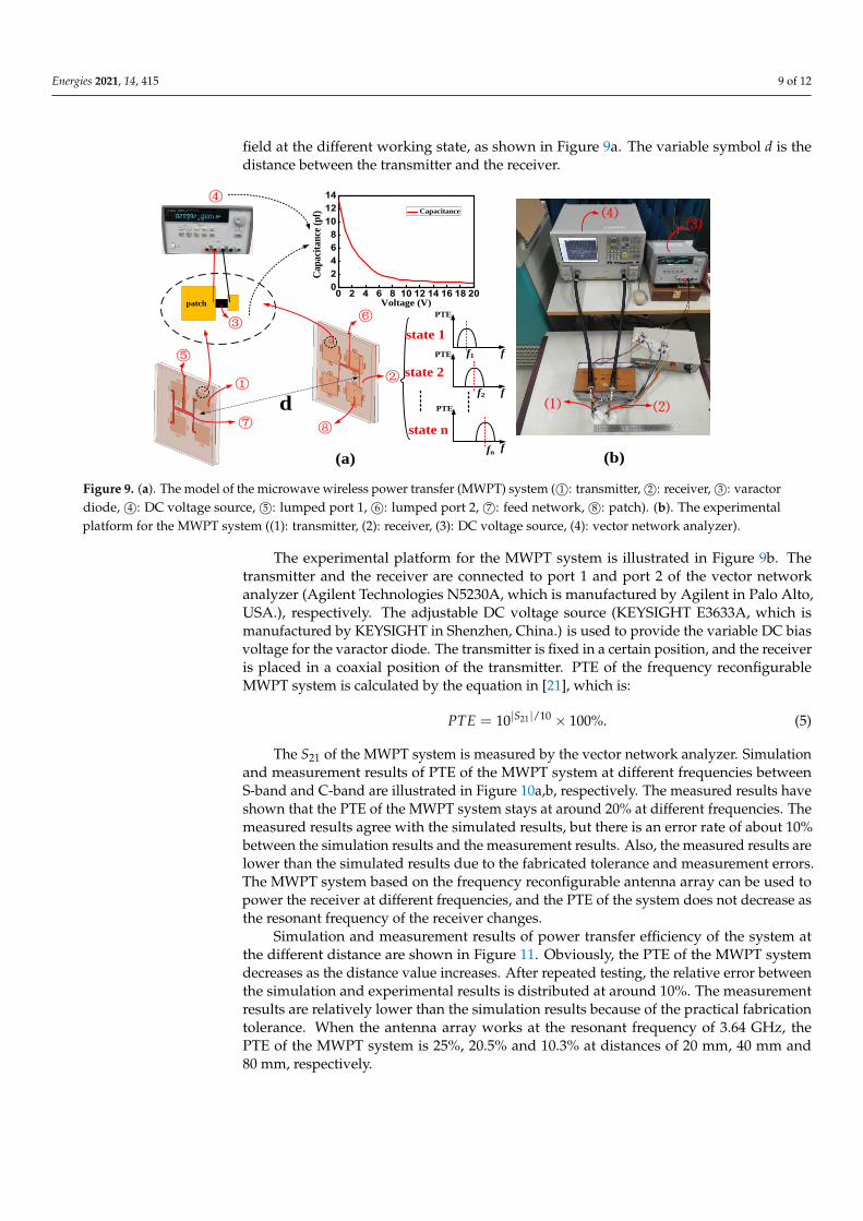
Figure 9. (a). The model of the microwave wireless power transfer (MWPT) system ( 1©: transmitter, 2©: receiver, 3©: varactordiode, 4©: DC voltage source, 5©: lumped port 1, 6©: lumped port 2, 7©: feed network, 8©: patch). (b). The experimentalplatform for the MWPT system ((1): transmitter, (2): receiver, (3): DC voltage source, (4): vector network analyzer).
The experimental platform for the MWPT system is illustrated in Figure 9b. Thetransmitter and the receiver are connected to port 1 and port 2 of the vector networkanalyzer (Agilent Technologies N5230A, which is manufactured by Agilent in Palo Alto,USA.), respectively. The adjustable DC voltage source (KEYSIGHT E3633A, which ismanufactured by KEYSIGHT in Shenzhen, China.) is used to provide the variable DC biasvoltage for the varactor diode. The transmitter is fixed in a certain position, and the receiveris placed in a coaxial position of the transmitter. PTE of the frequency reconfigurableMWPT system is calculated by the equation in [21], which is:
PTE = 10|S21|/10 × 100%. (5)
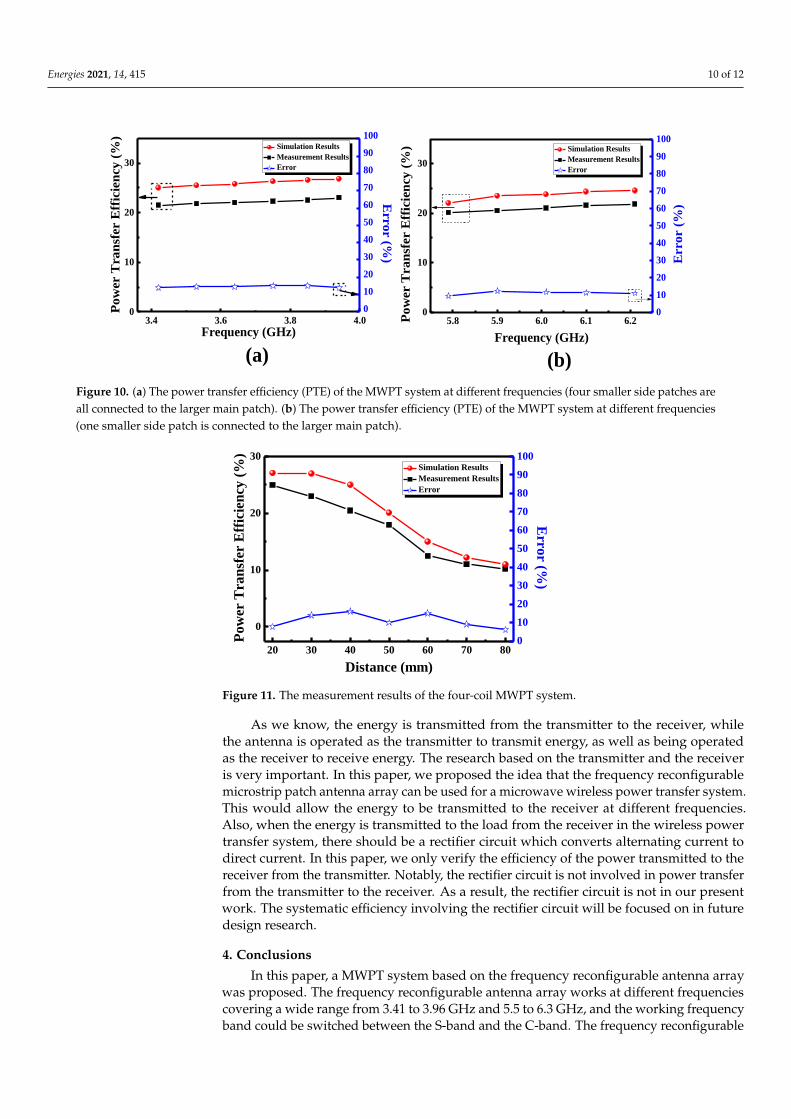
The S21 of the MWPT system is measured by the vector network analyzer. Simulationand measurement results of PTE of the MWPT system at different frequencies betweenS-band and C-band are illustrated in Figure 10a,b, respectively. The measured results haveshown that the PTE of the MWPT system stays at around 20% at different frequencies. Themeasured results agree with the simulated results, but there is an error rate of about 10%between the simulation results and the measurement results. Also, the measured results arelower than the simulated results due to the fabricated tolerance and measurement errors.The MWPT system based on the frequency reconfigurable antenna array can be used topower the receiver at different frequencies, and the PTE of the system does not decrease asthe resonant frequency of the receiver changes.
Simulation and measurement results of power transfer efficiency of the system atthe different distance are shown in Figure 11. Obviously, the PTE of the MWPT systemdecreases as the distance value increases. After repeated testing, the relative error betweenthe simulation and experimental results is distributed at around 10%. The measurementresults are relatively lower than the simulation results because of the practical fabricationtolerance. When the antenna array works at the resonant frequency of 3.64 GHz, thePTE of the MWPT system is 25%, 20.5% and 10.3% at distances of 20 mm, 40 mm and80 mm, respectively.
Energies 2021, 14, 415 10 of 12Energies 2021, 14, x FOR PEER REVIEW 10 of 12
(a) (b)
5.8 5.9 6.0 6.1 6.20
10
20
30
Simulation Results
Measurement Results
Error
Frequency (GHz)
Pow
er T
ran
sfer E
ffic
ien
cy (
%)
0
10
20
30
40
50
60
70
80
90
100
Error (
%)
3.4 3.6 3.8 4.00
10
20
30
Simulation Results
Measurement Results
Error
Frequency (GHz)
Pow
er T
ran
sfer E
ffic
ien
cy (
%)
0
10
20
30
40
50
60
70
80
90
100
Error (%
)
Figure 10. (a)The power transfer efficiency (PTE) of the MWPT system at different frequencies (four smaller side patches
are all connected to the larger main patch). (b) The power transfer efficiency (PTE) of the MWPT system at different fre-
quencies (one smaller side patch is connected to the larger main patch).
Simulation and measurement results of power transfer efficiency of the system at the
different distance are shown in Figure 11. Obviously, the PTE of the MWPT system de-
creases as the distance value increases. After repeated testing, the relative error between
the simulation and experimental results is distributed at around 10%. The measurement
results are relatively lower than the simulation results because of the practical fabrication
tolerance. When the antenna array works at the resonant frequency of 3.64 GHz, the PTE
of the MWPT system is 25%, 20.5% and 10.3% at distances of 20 mm, 40 mm and 80 mm,
respectively.
Figure 11. The measurement results of the four-coil MWPT system.
As we know, the energy is transmitted from the transmitter to the receiver, while the
antenna is operated as the transmitter to transmit energy, as well as being operated as the
receiver to receive energy. The research based on the transmitter and the receiver is very
important. In this paper, we proposed the idea that the frequency reconfigurable mi-
crostrip patch antenna array can be used for a microwave wireless power transfer sys-
tem. This would allow the energy to be transmitted to the receiver at different frequen-
cies. Also, when the energy is transmitted to the load from the receiver in the wireless
power transfer system, there should be a rectifier circuit which converts alternating cur-
rent to direct current. In this paper, we only verify the efficiency of the power transmitted
20 30 40 50 60 70 80
0
10
20
30
Simulation Results
Measurement Results
Error
Distance (mm)
Po
wer
Tra
nsf
er E
ffic
ien
cy (
%)
0
10
20
30
40
50
60
70
80
90
100
Erro
r (%)
Figure 10. (a) The power transfer efficiency (PTE) of the MWPT system at different frequencies (four smaller side patches areall connected to the larger main patch). (b) The power transfer efficiency (PTE) of the MWPT system at different frequencies(one smaller side patch is connected to the larger main patch).
Energies 2021, 14, x FOR PEER REVIEW 10 of 12
(a) (b)
5.8 5.9 6.0 6.1 6.20
10
20
30
Simulation Results
Measurement Results
Error
Frequency (GHz)
Pow
er T
ran
sfer E
ffic
ien
cy (
%)
0
10
20
30
40
50
60
70
80
90
100
Error (
%)
3.4 3.6 3.8 4.00
10
20
30
Simulation Results
Measurement Results
Error
Frequency (GHz)
Pow
er T
ran
sfer E
ffic
ien
cy (
%)
0
10
20
30
40
50
60
70
80
90
100
Error (%
)
Figure 10. (a)The power transfer efficiency (PTE) of the MWPT system at different frequencies (four smaller side patches
are all connected to the larger main patch). (b) The power transfer efficiency (PTE) of the MWPT system at different fre-
quencies (one smaller side patch is connected to the larger main patch).
Simulation and measurement results of power transfer efficiency of the system at the
different distance are shown in Figure 11. Obviously, the PTE of the MWPT system de-
creases as the distance value increases. After repeated testing, the relative error between
the simulation and experimental results is distributed at around 10%. The measurement
results are relatively lower than the simulation results because of the practical fabrication
tolerance. When the antenna array works at the resonant frequency of 3.64 GHz, the PTE
of the MWPT system is 25%, 20.5% and 10.3% at distances of 20 mm, 40 mm and 80 mm,
respectively.
Figure 11. The measurement results of the four-coil MWPT system.
As we know, the energy is transmitted from the transmitter to the receiver, while the
antenna is operated as the transmitter to transmit energy, as well as being operated as the
receiver to receive energy. The research based on the transmitter and the receiver is very
important. In this paper, we proposed the idea that the frequency reconfigurable mi-
crostrip patch antenna array can be used for a microwave wireless power transfer sys-
tem. This would allow the energy to be transmitted to the receiver at different frequen-
cies. Also, when the energy is transmitted to the load from the receiver in the wireless
power transfer system, there should be a rectifier circuit which converts alternating cur-
rent to direct current. In this paper, we only verify the efficiency of the power transmitted
20 30 40 50 60 70 80
0
10
20
30
Simulation Results
Measurement Results
Error
Distance (mm)
Po
wer
Tra
nsf
er E
ffic
ien
cy (
%)
0
10
20
30
40
50
60
70
80
90
100
Erro
r (%)
Figure 11. The measurement results of the four-coil MWPT system.
As we know, the energy is transmitted from the transmitter to the receiver, whilethe antenna is operated as the transmitter to transmit energy, as well as being operatedas the receiver to receive energy. The research based on the transmitter and the receiveris very important. In this paper, we proposed the idea that the frequency reconfigurablemicrostrip patch antenna array can be used for a microwave wireless power transfer system.This would allow the energy to be transmitted to the receiver at different frequencies.Also, when the energy is transmitted to the load from the receiver in the wireless powertransfer system, there should be a rectifier circuit which converts alternating current todirect current. In this paper, we only verify the efficiency of the power transmitted to thereceiver from the transmitter. Notably, the rectifier circuit is not involved in power transferfrom the transmitter to the receiver. As a result, the rectifier circuit is not in our presentwork. The systematic efficiency involving the rectifier circuit will be focused on in futuredesign research.
4. Conclusions
In this paper, a MWPT system based on the frequency reconfigurable antenna arraywas proposed. The frequency reconfigurable antenna array works at different frequenciescovering a wide range from 3.41 to 3.96 GHz and 5.5 to 6.3 GHz, and the working frequencyband could be switched between the S-band and the C-band. The frequency reconfigurable

Energies 2021, 14, 415 11 of 12
antenna array can work with good performance at different resonant frequencies. Thereturn loss of the frequency reconfigurable antenna array is less than−15 dB at the differentfrequencies. Radiation patterns of the antenna array at different frequencies are relativestable. Also, the gains of the antenna array are above 6 dBi at different working frequencies.In addition, PTE of the MWPT system based on the frequency reconfigurable antennaremains above 20% at different frequencies. Also, PTE of the MWPT system at the frequencyof 3.64 GHz is 25%, 20.5% and 10.3% at the distances of 20 mm, 40 mm and 80 mm,respectively. The MWPT system based on a frequency reconfigurable antenna array canbe used to power the receiver at different frequencies, and PTE of the system does notdecrease in a clear way as the resonant frequency of the receiver changes, which enablesthis system to greatly meet the demands of users.
Author Contributions: H.W. proposed the main idea. H.L. checked and discussed the results and thewhole manuscript. L.D., J.D., D.Z. and S.H. contributed to the discussion of this study. All authorshave read and agreed to the published version of the manuscript.
Funding: This research was funded by the National Key Research and Development Program ofChina (Grant No. 2017YFA0204600), and the National Natural Science Foundation of China (GrantNo. 51802352).
Institutional Review Board Statement: Not applicable.
Informed Consent Statement: Not applicable.
Data Availability Statement: Data sharing not applicable.
Conflicts of Interest: The authors declare no conflict of interest.
References1. Yang, Y.; Cui, J.; Cui, X. Design and Analysis of Magnetic Coils for Optimizing the Coupling Coefficient in an Electric Vehicle
Wireless Power Transfer System. Energies 2020, 13, 4143. [CrossRef]2. Seong, J.Y.; Lee, S.-S. Optimization of the Alignment Method for an Electric Vehicle Magnetic Field Wireless Power Transfer
System Using a Low-Frequency Ferrite Rod Antenna. Energies 2019, 12, 4689. [CrossRef]3. Baguley, C.A.; Jayasinghe, S.G.; Madawala, U.K. Theory and Control of Wireless Power Transfer Systems. In Control of Power
Electronic Converters and Systems; Academic Press: Cambridge, MA, USA, 2018; pp. 291–307.4. Frivaldsky, M.; Pavelek, M. In Loop Design of the Coils and the Electromagnetic Shielding Elements for the Wireless Charging
Systems. Energies 2020, 13, 6661. [CrossRef]5. Cruciani, S.; Campi, T.; Maradei, F.; Feliziani, M. Active Shielding Design and Optimization of a Wireless Power Transfer (WPT)
System for Automotive. Energies 2020, 13, 5575. [CrossRef]6. Zhang, C.; Chen, Y. Wireless power transfer strategies for cooperative relay system to maximize information throughput. IEEE
Access 2017, 5, 2573–2582. [CrossRef]7. Basar, M.R.; Ahmadm, M.Y.; Cho, J.; Ibrahim, F. Stable and high efficiency wireless power transfer system for robotic capsule
using a modified helmholtz coil. IEEE Trans. Ind. Electron. 2017, 64, 1113–1122. [CrossRef]8. Li, B.; Salem, N.P.M.H.; Giouroudi, I.; Kosel, J. Integration of thin film giant magneto impedance sensor and surface acoustic
wave transponder. J. Appl. Phys. 2012, 111, 07E514. [CrossRef]9. Aqueveque, P.; Gómez, B.; Monsalve, E.; Germany, E.; Ortega-Bastidas, P.; Dubo, S.; Pino, E.J. Simple Wireless Impedance
Pneumography System for Unobtrusive Sensing of Respiration. Sensors 2020, 20, 5228. [CrossRef]10. Zhang, Z.; Pang, H.; Georgiadis, A.; Cecati, C. Wireless power transfer—An overview. IEEE Trans. Ind. Electron. 2019, 66,
1044–1058. [CrossRef]11. Woo, D.-H.; Cha, H.-R.; Kim, R.-Y. Resonant Network Design Method to Reduce Influence of Mutual Inductance between
Receivers in Multi-Output Omnidirectional Wireless Power Transfer Systems. Energies 2020, 13, 5556. [CrossRef]12. Wan, S.; Huang, K. Methods for improving the transmission-conversion efficiency from transmitting antenna to rectenna array in
microwave power transmission. IEEE Antennas Wirel. Propag. Lett. 2018, 17, 538–542. [CrossRef]13. Shinohara, N.; Kubo, Y.; Tonomura, H. Mid-distance wireless power transmission for electric truck via microwaves. Proc. URSI
Int. Symp. Electromagn. Theory 2013, 841–843.14. Kawasaki, S. Microwave WPT to a rover using active integrated phased array antennas. Proc. Eur. Conf. Antennas Propag. 2011,
3909–3912.15. Shinohara, N. Recent wireless power transmission via microwave and millimeter-wave in Japan. Proc. IEEE Microw. Conf. 2012,
20, 7843–7848.

Energies 2021, 14, 415 12 of 12
16. Li, Y.; Jandhyala, V. Design of retrodirective antenna arrays for short-range wireless power transmission. IEEE Trans. AntennasPropag. 2012, 60, 206–211. [CrossRef]
17. Franceschetti, G.; Massa, A.; Rocca, P. Innovative antenna systems for efficient microwave power collection. In Proceedings ofthe 2011 IEEE MTT-S International Microwave Workshop Series on Innovative Wireless Power Transmission: Technologies, Systems, andApplications; IEEE: Piscataway, NJ, USA, 2011; pp. 275–278.
18. Oliveri, G.; Rocca, P.; Viani, F.; Robol, F.; Massa, A. Latest advances and innovative solutions in antenna array synthesis formicrowave wireless power transmission. In Proceedings of the 2012 IEEE MTT-S International Microwave Workshop Series onInnovative Wireless Power Transmission: Technologies, Systems, and Applications; IEEE: Piscataway, NJ, USA, 2012; pp. 71–73.
19. Manica, L.; Rocca, P.; Martini, A.; Massa, A. An innovative approach based on a tree-searching algorithm for the optimal matchingof independently optimum sum and difference excitations. IEEE Trans. Antennas Propag. 2008, 56, 58–66. [CrossRef]
20. Gowda, V.R.; Yurduseven, O.; Lipworth, G.; Zupan, T.; Reynolds, M.S.; Smith, D.R. Wireless power transfer in the radiative nearfield. IEEE Antennas Wirel. Propag. Lett. 2016, 15, 1865–1868. [CrossRef]
21. Yang, X.; Wen, G.; Sun, H. Optimum design of wireless power transmission system using microstrip patch antenna arrays. IEEEAntennas Wirel. Propag. Lett. 2017, 16, 1824–1827. [CrossRef]
22. Kim, Y.; Ha, D.; Chappell, W.J.; Irazoqui, P.P. Selective wireless power transfer for smart power distribution in a miniature-sizedmultiple-receiver system. IEEE Trans. Ind. Electron. 2016, 63, 1853–1862. [CrossRef]
23. Dai, Z.; Fang, Z.; Huang, H.; He, Y.; Wang, J. Selective Omnidirectional Magnetic Resonant Coupling Wireless Power Transferwith Multiple-Receiver System. IEEE Access 2018, 6, 19287–19294. [CrossRef]
24. Zhong, W.; Hui, S.Y. Reconfigurable wireless power transfer systems with high energy efficiency over wide load range. IEEETrans. Power Electron. 2018, 33, 6379–6390. [CrossRef]
25. Duong, T.P.; Lee, J.W. Experimental results of high-efficiency resonant coupling wireless power transfer using a variable couplingmethod. IEEE Microw. Wirel. Compon. Lett. 2011, 21, 442–444. [CrossRef]
26. Liu, Z.; Chen, Z.; Li, J.; Zhao, H. A shape-reconfigurable modularized wireless power transfer array system for multipurposewireless charging applications. IEEE Trans. Antennas Propag. 2018, 66, 4252–4259. [CrossRef]
27. Dang, Z.; Cao, Y.; Qahouq, J.A.A. Reconfigurable magnetic resonance-coupled wireless power transfer system. IEEE Trans. PowerElectron. 2018, 33, 6057–6069. [CrossRef]
28. Shimu, N.J.; Ahmed, A. Design and performance analysis of rectangular microstrip patch antenna at 2.45 GHz. In Proceedings ofthe 2016 5th International Conference on Informatics, Electronics and Vision (ICIEV), Dhaka, Bangladesh, 13–14 May 2016; pp.1062–1066.
29. Elfatimi, A.; Bri, S.; Saadi, A. Comparison between techniques feeding for simple rectangular, circular and triangular patchantenna at 2.45 GHz. In Proceedings of the 2018 4th International Conference on Optimization and Applications (ICOA),Mohammedia, Morocco, 26–27 April 2018; pp. 1–5.
30. Yadav, M.B.; Singh, B.; Melkeri, V.S. Design of rectangular microstrip patch antenna with DGS at 2.45 GHz. In Proceedings of the2017 International conference of Electronics, Communication and Aerospace Technology (ICECA), Coimbatore, India, 20–22April 2017; pp. 367–370.