Embed Size (px)
Citation preview

User's Manual
Benutzerhandbuch
Mode d’emploi
Manual del usuario
Manuale dell’utente
Manual do Utilizador
安裝說明書
用戶手冊
ユーザーズマニュアル
Руководство пользователя
kullanıcı elkitabı
(EEE Yönetmeliğine Uygundur)
คู ่ม ือการใช้
© 2019 Thermaltake Technology Co., Ltd. All Rights Reserved. A-2019.04All other registered trademarks belong to their respective companies. www.thermaltake.com
Mid Tower
H 200 TG
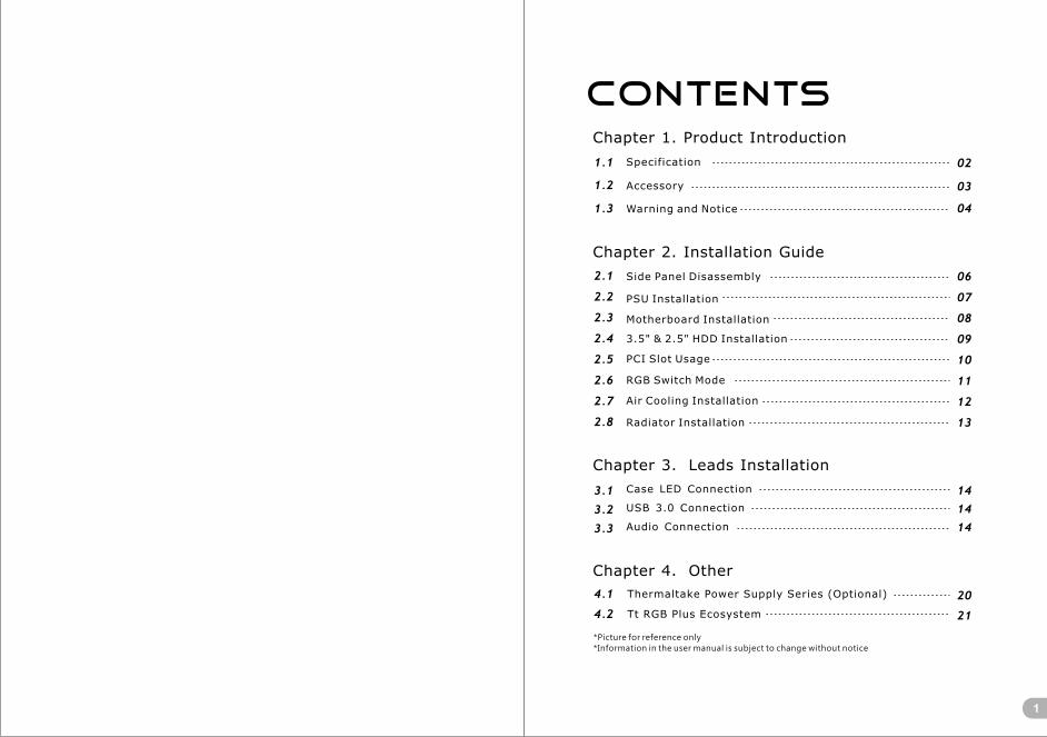
Contents
1
Chapter 1. Product Introduction
Chapter 2. Installation Guide
2.1
2.2
2.3
2.4
2.5
2.6
2.7
2.8
1.1
1.2
1.3
02
03
04
06
07
08
09
10
11
12
13
Specification
Accessory
Warning and Notice
Side Panel Disassembly
PSU Installation
Motherboard Installation
3.5" & 2.5" HDD Installation
Chapter 3. Leads Installation
Case LED Connection
USB 3.0 Connection
Audio Connection
3.1
3.2
3.3
14
14
14
Chapter 4. Other
4.1
4.2
20
21
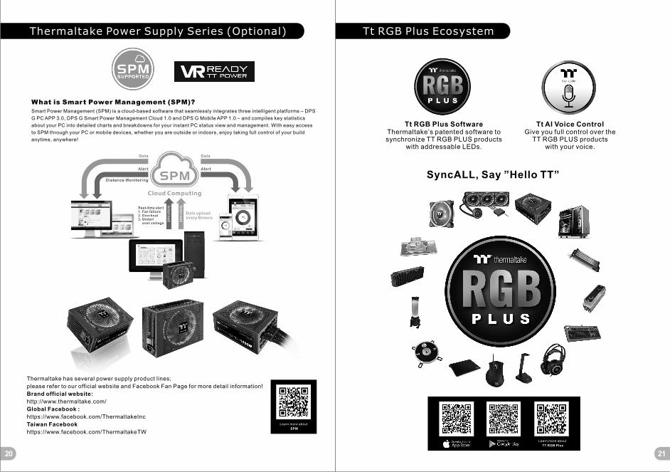
Thermaltake Power Supply Series (Optional)
Tt RGB Plus Ecosystem
*Picture for reference only
*Information in the user manual is subject to change without notice
PCI Slot Usage
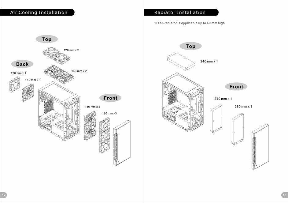
Air Cooling Installation
RGB Switch Mode
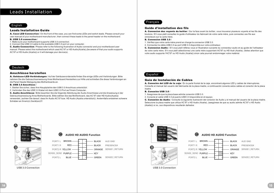
Radiator Installation

2 3
Stand-off #6-32 x 6mm
Stand-off tool Stand-off
Parts Name Q’ty Used forFigure
Screw #6-32 x 6mm
Screw #6-32 x 10mm
Screw M3 x 5mm
Screw M3 x 5mm
HDD/SSD Rubber
Screw M3 x 5mm
Screw T5 x 12mm
Movable Tie
Buzzer
9
1
4
8
4
4
12
8
10
Power Supply
3.5"HDD
Motherboard
Motherboard
Motherboard Alarm
Case Fan
Cable Management
3
1
2.5"SSD
2.5"SSD
2.5"SSD/ 3.5"HDD
H200 TG RGB
Middle tower
4mm Tempered Glass x 1
Front: 1 x 240 mm, 1 x 280 mm
Top: 1 x 240 mm
USB 3.0 x 2, HD Audio x 1, RGB Button x 1
CPU cooler height limitation: 180 mm
VGA length limitation: 320 mm
Model
Case Type
Chassis Dimension(H*W*D)
416 x 210 x 454 mm (16.4 x 8.3 x 17.9 inch)
Side Panel
Cooling System
Radiator Support
I/O Port
Clearance
Drive Bays
- Accessible
- Hidden
Rear (exhaust) :
120 x 120 x 25 mm fan (1000 rpm, 26 dBA)
-
2 x 2.5“ or 3 x 3.5”
H200 TG RGB Snow Editon
7Expansion Slots
6.7” x 6.7” (Mini ITX), 9.6” x 9.6” (Micro ATX), 12” x 9.6” (ATX)Motherboards

4 5
Warning and Notice
<180 mm
<320 mm
CPU Cooler Height Limitation VGA (Add-on card) Length Limitation
Warning!!
- Height limit for the CPU heatsink:
The height limit for the CPU heatsink is 180 mm (7.1 inches).
- Length limit for the VGA (graphics card):
The length limit for the VGA (graphics card) is 320 mm (12.6 inches).
Warnung!!
- Höhenbeschränkung für CPU-Kühler:
Die Höhenbeschränkung für den CPU-Kühler liegt bei 180 mm (7,1 Zoll).
- Längenbeschränkung für die VGA (Grafikkarte):
Die Längenbeschränkung für die VGA (Grafikkarte) beträgt 320 mm (12,6 Zoll).
Avertissement !
- Hauteur limite du dissipateur thermique du processeur :
La hauteur limite du dissipateur thermique du processeur est de 180 mm (7,1 pouces).
- Longueur limite de la carte VGA (carte graphique) :
La longueur limite de la carte VGA (carte graphique) est de 320 mm (12,6 pouces).
Precaución
- Límite de altura para el disipador de calor de la CPU:
El límite de altura para el disipador de calor de la CPU es de 180 mm (7,1 pulgadas).
- Límite de longitud para la tarjeta gráfica (VGA):
El límite de longitud para la tarjeta gráfica (VGA) en de 320 mm (12,6 pulgadas).
Attenzione!
- Limite di altezza per il dissipatore di calore della CPU:
Il limite di altezza per il dissipatore di calore della CPU è 180 mm (7,1’’).
- Limite di lunghezza per la VGA (schede grafiche):
Il limite di lunghezza per la VGA (scheda grafica) è 320 mm (12,6’’).
Atenção!!
- Limite de altura para o dissipador do CPU:
O limite de altura para o dissipador do CPU é 180 mm (7,1 polegadas).
- Limite de comprimento para VGA (placa gráfica):
O limite de comprimento para VGA (placa gráfica) é 320 mm (12,6 polegadas).
警告!!
- CPU散熱器的高度限制:
CPU散熱器的高度限制為180mm(7.1英吋)。
- VGA(顯示卡)的長度限制:
VGA(顯示卡)的長度限制為320mm(12.6英吋)。
警告!!
- CPU散热器的高度限制:
CPU散热器的高度限制为180mm(7.1英寸)。
- VGA(显卡)的长度限制:
VGA(显卡)的长度限制为320mm(12.6英寸)。
警告
- CPUヒートシンクの高さ制限:
CPUヒートシンクの高さ制限は180 mmです。
- VGA(グラフィックスカード)の長さ制限:
VGA(グラフィックスカード)の長さ制限は320 mmです。
Внимание!
- Ограничение по высоте для радиатора ЦП.
Ограничение по высоте для радиатора ЦП составляет 180 мм (7,1 дюйма).
- Ограничение по длине для платы VGA (графическая плата).
Ограничение по длине для платы VGA (графическая плата) составляет 320 мм (12.6 дюйма).
Uyarı!!
- CPU ısı alıcısı için yükseklik sınırı:
CPU ısı alıcısı için yükseklik sınırı 180 mm’dir (7,1 inç).
- VGA (grafik kartı) için uzunluk sınırı:
VGA (grafik kartı) için uzunluk sınırı 320 mm’dir (12,6 inç).
คำเตือน!!
- ขีดจำกัดความสูงสำหรับฮีตซิงก์ของ CPU:
ขีดจำกัดความสูงสำหรับฮีตซิงก์ของ CPU คือ 180 มม. (7.1นิ ้ว)
- ขีดจำกัดความยาวสำหรับ VGA (การ์ดแสดงผล):
ขีดจำกัดความยาวสำหรับ VGA (การ์ดแสดงผล) คือ 320 มม. (12.6 นิ ้ว)
6 7
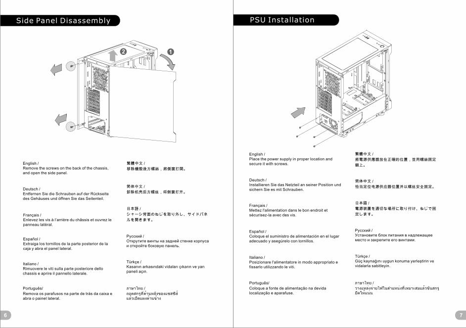
Side Panel Disassembly PSU Installation
English /Remove the screws on the back of the chassis, and open the side panel.
Deutsch /Entfernen Sie die Schrauben auf der Rückseite des Gehäuses und öffnen Sie das Seitenteil.
Français /Enlevez les vis à l’arrière du châssis et ouvrez le panneau latéral.
Español /Extraiga los tornillos de la parte posterior de la caja y abra el panel lateral.
Italiano /Rimuovere le viti sulla parte posteriore dello chassis e aprire il pannello laterale.
Português/
Remova os parafusos na parte de trás da caixa e abra o painel lateral.
繁體中文 /
移除機殼後方螺絲,將側窗打開。
日本語 /
シャーシ背面のねじを取り外し、サイドパネ
ルを開きます。
Русский /Открутите винты на задней стенке корпуса и откройте боковую панель.
简体中文 /
卸除机壳后方螺丝,将侧窗打开。
Türkçe /Kasanın arkasındaki vidaları çıkarın ve yan paneli açın.
ภาษาไทย /
ถอดสกรูที่ด้านหลังของแชสซีส์ แล้วเปิดแผงด้านข้าง
English /Place the power supply in proper location and secure it with screws.
Deutsch /Installieren Sie das Netzteil an seiner Position und sichern Sie es mit Schrauben.
Français /Mettez l'alimentation dans le bon endroit et sécurisez-la avec des vis.
Español /Coloque el suministro de alimentación en el lugar adecuado y asegúrelo con tornillos.
Italiano /Posizionare l'alimentatore in modo appropriato e fissarlo utilizzando le viti.
Português/
Coloque a fonte de alimentação na devida localização e aparafuse.
简体中文 /
恰当定位电源供应器位置并以螺丝安全固定。
日本語 /
電源装置を適切な場所に取り付け、ねじで固
定します。
Русский /Установите блок питания в надлежащее место и закрепите его винтами.
繁體中文 /
將電源供應器放在正確的位置,並用螺絲固定
鎖上。
Türkçe /Güç kaynağını uygun konuma yerleştirin ve vidalarla sabitleyin.
ภาษาไทย /
วางแหล่งจ่ายไฟในตำแหน่งที่เหมาะสมแล้วขันสกรูยึดให้แน่น
12
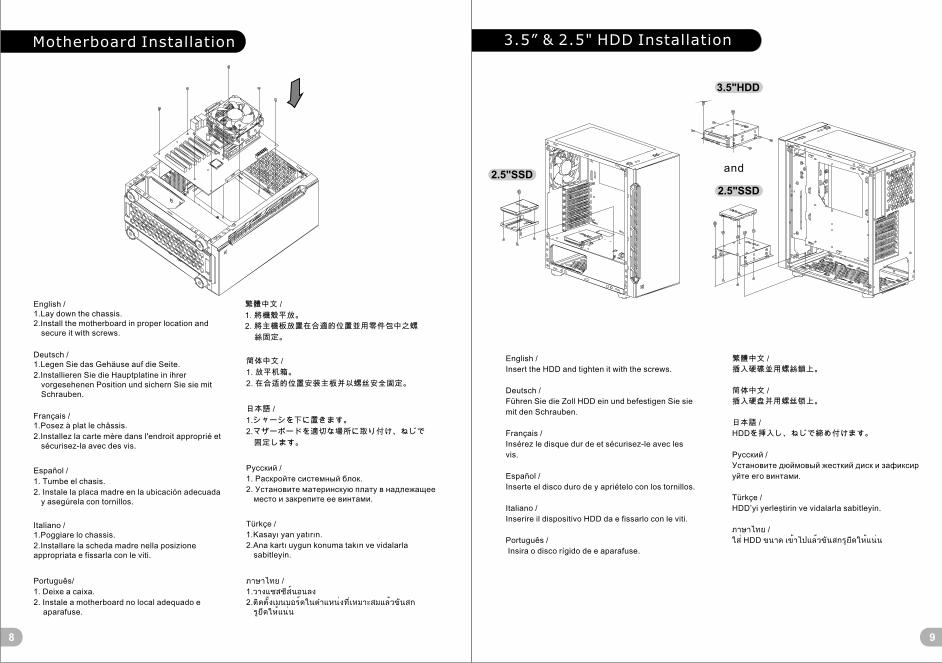
Motherboard Installation
8 9
English /1.Lay down the chassis.2.Install the motherboard in proper location and
secure it with screws.
Deutsch /1.Legen Sie das Gehäuse auf die Seite.
2.Installieren Sie die Hauptplatine in ihrer vorgesehenen Position und sichern Sie sie mit Schrauben.
Français /1.Posez à plat le châssis.
2.Installez la carte mère dans l'endroit approprié et sécurisez-la avec des vis.
Español /
1. Tumbe el chasis.
2. Instale la placa madre en la ubicación adecuada y asegúrela con tornillos.
Italiano /1.Poggiare lo chassis.
2.Installare la scheda madre nella posizione appropriata e fissarla con le viti.
Português/
1. Deixe a caixa.
2. Instale a motherboard no local adequado e aparafuse.
繁體中文 /
1. 將機殼平放。
2. 將主機板放置在合適的位置並用零件包中之螺
絲固定。
日本語 /
1.シャーシを下に置きます。
2.マザーボードを適切な場所に取り付け、ねじで
固定します。
Русский /
1. Раскройте системный блок.
2. Установите материнскую плату в надлежащее место и закрепите ее винтами.
简体中文 /
1. 放平机箱。
2. 在合适的位置安装主板并以螺丝安全固定。
Türkçe /
1.Kasayı yan yatırın.
2.Ana kartı uygun konuma takın ve vidalarla sabitleyin.
ภาษาไทย /
1.วางแชสซีส์นอนลง
2.ติดตั้งเมนบอร์ดในตำแหน่งที่เหมาะสมแล้วขันสกรูยึดให้แน่น
3.5” & 2.5" HDD Installation
English /
Insert the HDD and tighten it with the screws.
Deutsch /
Führen Sie die Zoll HDD ein und befestigen Sie sie
mit den Schrauben.
Français /
Insérez le disque dur de et sécurisez-le avec les
vis.
Español /
Inserte el disco duro de y apriételo con los tornillos.
Italiano /
Inserire il dispositivo HDD da e fissarlo con le viti.
Português /
Insira o disco rígido de e aparafuse.
繁體中文 /
插入硬碟並用螺絲鎖上。
简体中文 /
插入硬盘并用螺丝锁上。
日本語 /
HDDを挿入し、ねじで締め付けます。
Русский /
Установите дюймовый жесткий диск и зафиксир
уйте его винтами.
Türkçe /
HDD’yi yerleştirin ve vidalarla sabitleyin.
ภาษาไทย /
ใส ่ HDD ขนาด เข้าไปแล้วขันสกรูยึดให้แน่น
and
3.5"HDD
2.5"SSD
2.5"SSD

PCI Card Installation
Português /
1. Desaperte os parafusos com a chave de fendas.
2. Instale a placa PCI no local adequado e
aparafuse.
English /
1. Loosen the screws with a screwdriver.
2. Install the PCI card in proper location and secure
it with screws.
Deutsch /
1. Lösen Sie die Schrauben mit einem
Schraubendreher.
2. Installieren Sie die PCI-Card in der
vorgesehenen Position und sichern Sie sie mit
Schrauben.
Français /
1. Desserrez les vis à l’aide d’un tournevis.
2. Installez la carte PCI dans l'endroit approprié et
fixez-la avec des vis.
Español /
1. Afloje los tornillos con un destornillador.
2. Instale la tarjeta PCI en la ubicación adecuada y
asegúrela con tornillos.
Italiano /
1. Allentare le viti con un cacciavite.
2. Installare la scheda PCI nella posizione
appropriata e fissarla con le viti.
ภาษาไทย /
1. ใช้ไขควงขันสกรูออก
2. ติดตั้งการ์ด PCI
ในตำแหน่งที่เหมาะสมแล้วขันสกรูยึดให้แน่น
繁體中文 /
1. 用螺絲起子將螺絲取下.
2. 將擴充卡放置在合適的位置並用螺絲固定。
日本語 /
1.ドライバーでねじを緩めます。
2. PCI カードを適切な場所に取り付け、ねじで固
定します。
简体中文 /
1. 用螺丝起子将螺丝取下.
2. 将扩充卡放置在合适的位置并用螺丝固定。
Türkçe /
1. Vidaları, bir tornavida ile gevşetin.
2. PCI kartını uygun konuma takın ve vidalarla
sabitleyin.
Русский /
1. Ослабьте винты отверткой.
2. Установите плату PCI в надлежащий разъем
и закрепите ее винтами.
1110
Flow Mode
Flow Mode
Wave Mode
RGB Mode
Breath Mode
Full Lighted Mode
Full Lighted Mode
Mode 2 (Single Color)
Mode 1
Mode 3
Mode 4 (Single Color)
Mode 5~11(Red, Green, Blue, Pink, Cyan, Yellow, White)
Mode 12~18(Red, Green, Blue, Pink, Cyan, Yellow, White)
Mode 19
RGB Switch Mode
I/O Port
※ Long press the RGB button for 3 seconds to TURN OFF the lighting strip.
Radiator InstallationAir Cooling Installation
※The radiator is applicable up to 40 mm high
1312
140 mm x 2
120 mm x3
120 mm x 2
140 mm x 2120 mm x 1
140 mm x 1
Top
Front
Front
Back240 mm x 1
280 mm x 1
240 mm x 1
Top
Leads Installation
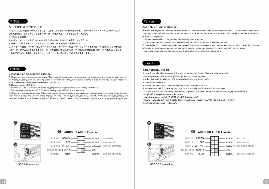
Leads Installation GuideA. Case LED Connection / On the front of the case, you can find some LEDs and switch leads. Please consult your
user manual of your motherboard manufacturer, then connect these leads to the panel header on the motherboard.
B. USB 3.0 connection / 1. Make sure your motherboard supports USB 3.0 connection.2. Connect the USB 3.0 cable to the available USB 3.0 port on your computer.
C. Audio Connection / Please refer to the following illustration of Audio connector and your motherboard user
manual. Please select the motherboard which used AC’97 or HD Audio(Azalia),(be aware of that your audio supports
AC’97 or HD Audio (Azalia)) or it will damage your device(s).
Anschlüsse herstellenA. Gehäuse-LED-Verbindungen / Auf der Gehäusevorderseite finden Sie einige LEDs und Verbindungen. Bitte
nehmen Sie die Gebrauchsanweisung Ihres Motherboard Herstellers zur Hilfe und schließen Sie diese Verbindungen an
die Panel Header Belegung des Motherboards an.
B. USB 3.0 Anschluss /
1. Stellen Sie sicher, dass Ihre Hauptplatine den USB 3.0 Anschluss unterstützt.
2. Verbinden Sie das USB 3.0 Kabel mit dem USB 3.0 Port auf Ihrem Computer.
C. Audio Anschlüsse / Bitte beachten Sie die folgende Abbildung der Audio Anschlüsse und die Anweisung in der
Gebrauchsanweisung Ihres Motherboards. Bitte wählen Sie das Motherboard, das AC’97 oder HD Audio(Azalia)
verwendet, (achten Sie darauf, dass Ihr Audio AC’97 bzw. HD Audio (Azalia unterstützt)). Andernfalls entstehen schwere
Schäden an Ihrem(n) Gerät(en)!!!
USB 3.0 Connection USB 3.0 Connection
PRESENCE# PRESENCE#BLACK BLACK
SENSE1_RETURN SENSE1_RETURN
AUD GND AUD GND
SENSE2_RETURN SENSE2_RETURN
YELLOW YELLOW
BROWN BROWN
RED REDPORT1 R PORT1 R
PORT2 R PORT2 R
PORT1 L PORT1 L
BLUE BLUEPORT2 L PORT2 L
SENSE_SEND SENSE_SENDKEY KEYPURPLE PURPLE
GREEN GREEN
ORANGE ORANGE
BLACK BLACK
AUDIO HD AUDIO Function AUDIO HD AUDIO Function
English
Deutsch
Guide d'installation des filsA. Connexion des voyants du boîtier / Sur la face avant du boîtier, vous trouverez plusieurs voyants et les fils des
boutons. S'il vous plaît consultez le guide d'utilisateur du fabricant de votre carte mère, puis connectez ces fils aux
onnecteurs sur la carte mère.
B. Connexion USB 3.0 /
1. Vérifiez que votre carte mère prend en charge la connexion USB 3.0.
2. Connectez le câble USB 3.0 au port USB 3.0 disponible sur votre ordinateur.
C. Connexion Audio / S'il vous plaît référez vous à l'illustration suivante du connecteur audio et au guide de l'utilisateur
de votre carte mère. S'il vous plaît sélectionnez une carte mère supportant AC'97 ou HD Audi (Azalia), (faites attention que
votre audio supporte l'AC'97 ou HD Audio (Azalia)) sinon cela pourrait endommager votre matériel.
Guía de Instalación de CablesA. Conexión del LED de la caja / En la parte frontal de la caja, encontrará algunos LED y cables de interruptores.
Consulte el manual del usuario del fabricante de la placa madre, a continuación conecte estos cables al conector de la placa
madre.
B. Conexión USB 3.0 /
1. Asegúrese de que la placa base admite conexión USB 3.0.
2. Conecte el cable USB 3.0 al puerto USB 3.0 disponible en el equipo.
C. Conexión de Audio / Consulte la siguiente ilustración del conector de Audio y el manual del usuario de la placa madre.
Seleccione la placa madre que utiliza AC’97 o HD Audio (Azalia), (asegúrese de que su audio admite AC’97 o HD Audio
(Azalia)) si no, sus dispositivos resultarán dañados
Français
Español
14 15
A A
B B
C C

Guida di installazione dei contattiA. Connessione del LED del case / Nella parte anteriore del case, sono presenti alcuni contatti per interruttori e LED.
Consultare il manuale utente del produttore della scheda madre, quindi connettere i contatti alla parte superiore del
pannello sulla scheda madre.
B. Connessione USB 3.0 /
1. Accertarsi che la scheda madre supporti la connessione USB 3.0.
2. Collegare il cavo USB 3.0 alla porta USB 3.0 disponibile sul computer.
C. Connessione Audio / Fare riferimento all’illustrazione riportata di seguito del connettore Audio e al manuale utente
per la scheda madre.Selezionare la scheda madre relativa a AC’97 o HD Audio (Azalia) e considerare che il supporto audio
è compatibile con AC’97 o HD Audio (Azalia); in caso contrario, le periferiche potrebbero venire danneggiate.
Guia de Instalação EléctricaA. Ligação do LED da Caixa / Na parte dianteira da caixa pode encontrar alguns LEDs e fios eléctricos. Consulte o
manual de utilizador do fabricante da sua motherboard e ligue os fios à parte superior do painel na motherboard.
B. Ligação USB 3.0 /
1. Certifique-se que a sua motherboard suporta ligação USB 3.0.
2. Ligue o cabo USB 3.0 à porta USB 3.0 disponível no seu computador.
C. Ligação Áudio / Consulte a imagem seguinte do conector Áudio e o manual de utilizador da sua motherboard.
Seleccione a motherboard que utiliza AC’97 ou HD Áudio(Azalia), (verifique se a sua placa de áudio suporta AC’97 ou HD
Áudio(Azalia)) ou irá danificar o(s) seu(s) dispositivo(s).
Italiano
Português
線材安裝說明A. 機殼LED連接方式 / 在機殼前方的面板後面,可以找到一些LED與開關線材(POWER Switch….),請參考主機板使用說明
書,並將機殼上的線材正確地連接到主機板上,這些線材通常都會印有標籤在上面,如果沒有的話,請找出機殼前方面板上線
材原本的位置以知道正確的來源。
B. USB 3.0 連接 /
1. 請確認主機板是否支援USB 3.0傳輸介面。
2. 連接USB 3.0傳輸線至主機板上的USB3.0接埠。
C. 音效連接 / 請根據下面的音源接頭圖示與主機板使用手冊來連接音效裝置,請確認主機板上的音效裝置是支援AC' 97音效或
是HD音效(Azalia),裝置錯誤可能會導致主機板音效裝置的毀損,某些主機板的音效裝置不會與下方的圖示完全相同,請參酌
主機板使用手冊以得到正確的安裝資訊
线材安装说明
A. 机壳LED连接方式 / 在机壳前方的面板后面,可以找到一些LED与开关线材(POWER Switch….),请参考主板使用说明
书,并将机壳上的线材正确地连接到主板上,这些线材通常都会印有标签在上面,如果没有的话,请找出机壳前方面板上线
材原本的位置以知道正确的来源。
B. USB 3.0 连接 /
1.请确认主板是否支持USB 3.0传输接口。
2.连接USB 3.0传输线至主板上的USB3.0接埠。
音效连接 / 请根据下面的音源接头图示与主板使用手册来连接音效装置,请确认主板上的音效装置是支持AC' 97音效或是
C. HD音效(Azalia),装置错误可能会导致主板音效装置的毁损,某些主板的音效装置不会与下方的图标完全相同,请参酌主
板使用手册以得到正确的安装信息
繁體中文
简体中文
16 17
USB 3.0 Connection USB 3.0 Connection
PRESENCE# PRESENCE#BLACK BLACK
SENSE1_RETURN SENSE1_RETURN
AUD GND AUD GND
SENSE2_RETURN SENSE2_RETURN
YELLOW YELLOW
BROWN BROWN
RED REDPORT1 R PORT1 R
PORT2 R PORT2 R
PORT1 L PORT1 L
BLUE BLUEPORT2 L PORT2 L
SENSE_SEND SENSE_SENDKEY KEYPURPLE PURPLE
GREEN GREEN
ORANGE ORANGE
BLACK BLACK
AUDIO HD AUDIO Function AUDIO HD AUDIO Function
A A
B B
C C
Указания по прокладке кабелейA. Подключение индикаторов корпуса / В передней части корпуса расположены индикаторы и провода выключател
ей. Перед подсоединением этих проводов к монтажной колодке панели на материнской плате изучите руководство
пользователя производителя материнской платы.
B. Подключение USB 3.0 /
1. Убедитесь, что материнская плата поддерживает подключение по стандарту USB 3.0.
2. Подсоедините кабель USB 3.0 к свободному порту USB 3.0 компьютера.
C. Подключение аудиоразъема / См. следующую иллюстрацию аудиоразъема и руководство пользователя материн
ской платы. Выберите материнскую плату, в которой используется кодек AC'97 или HD Audio (Azalia) (убедитесь, что
звуковая плата поддерживает кодек AC'97 или HD Audio (Azalia)). В противном случае можно повредить устройства.
リード線の取り付けガイド
A. ケース LED の接続 / ケース前面には、LEDとスイッチリード線があります。 マザーボードメーカーのユーザーマニュ
アルを参照し、これらのリード線をマザーボードのパネルヘッダに接続してください。
B. USB 3.0 の接続 /
1. お使いのマザーボードがUSB 3.0接続をサポートしていることを確認してください。
2. USB 3.0ケーブルをコンピュータの空いているUSB 3.0ポートに接続します。
C. オーディオ接続 / オーディオコネクタの次の図とマザーボードのユーザーマニュアルを参照してください。AC’97または
HDオーディオ(Azalia)を使用するマザーボードを選択してください(オーディオがAC’97またはHDオーディオ(Azalia)をサポ
ートしていることを確認してください)。サポートしていないと、デバイスが損傷します)。
日本語
Русский
Ara Kablo Kurulum KılavuzuA. Kasa ışık bağlantısı / Kasanın ön kısmında bazı ışıklar ve anahtar ara kabloları görebilirsiniz. Lütfen anakart üreticinizin
sağladığı kullanım kılavuzuna bakın ve daha sonra, bu ara kabloları, anakart üzerindeki panel bağlantı noktalarına bağlayın.
B. USB 3.0 Bağlantısı /
1. Ana kartınızın USB 3.0 bağlantısını desteklediğinden emin olun.
2. USB 3.0 kablosunu, bilgisayarınızdaki kullanılabilir USB 3.0 bağlantı noktasına bağlayın.
C. Ses Bağlantısı / Lütfen aşağıdaki Ses konektörü resmine ve anakartınızın kullanım kılavuzuna bakın. Lütfen AC’97 veya
HD Audio(Azalia) spesifikasyonunu kullanan bir anakart seçin (ses sisteminizin AC’97 veya HD Audio (Azalia)
spesifikasyonunu desteklediğini unutmayın); aksi takdirde, aygıt(lar)ınız zarar görür.
คู ่ม ือการติดตั ้งสายไฟ
A. การเชื ่อมต่อไฟ LED ของเคส / ที ่ด ้านหน้าของเคส คุณจะเห็นไฟ LED และสายไฟของสวิตซ์
กรุณาศึกษารายละเอียดจากคู ่ม ือผู ้ใช้ของผู ้ผลิตแผงวงจรหลักของคุณ
จากนั ้นให้เชื ่อมต่อสายไฟเหล่านี ้เข้ากับส่วนหัวของแผงบนแผงวงจรหลัก
B. การเชื ่อมต่อ USB 3.0 /
1. ตรวจดูให้แน่ใจว่าแผงวงจรหลักของคุณรองรับการเชื ่อมต่อ USB 3.0
2. เชื ่อมต่อสาย USB 3.0 เข้ากับพอร์ต USB 3.0 ที ่สามารถใช้งานได้บนคอมพิวเตอร์ของคุณ
C. การเชื ่อมต่ออุปกรณ์รับส่งสัญญาณเสียง/ กรุณาดูรายละเอียดจากภาพประกอบของตัวเชื ่อมต่อสัญญาณเสียงต่อไปนี ้
และคู ่มือผู ้ใช้ของผู ้ผลิตแผงวงจรหลักของคุณ
กรุณาเลือกแผงวงจรหลักที ่ใช้ AC’97 หรือ HD Audio(Azalia)
(กรุณาตรวจสอบให้แน่ใจว่าอุปกรณ์ร ับส่งสัญญาณเสียงของคุณรองรับ AC’97 หรือ HD Audio (Azalia))
มิฉะนั ้นอุปกรณ์ของคุณอาจเสียหายได้
Türkçe
ภาษาไทย
18 19
USB 3.0 Connection USB 3.0 Connection
PRESENCE# PRESENCE#BLACK BLACK
SENSE1_RETURN SENSE1_RETURN
AUD GND AUD GND
SENSE2_RETURN SENSE2_RETURN
YELLOW YELLOW
BROWN BROWN
RED REDPORT1 R PORT1 R
PORT2 R PORT2 R
PORT1 L PORT1 L
BLUE BLUEPORT2 L PORT2 L
SENSE_SEND SENSE_SENDKEY KEYPURPLE PURPLE
GREEN GREEN
ORANGE ORANGE
BLACK BLACK
AUDIO HD AUDIO Function AUDIO HD AUDIO Function
A A
B B
C C
20 21