Embed Size (px)
Citation preview
Commercial Air Conditioners
ServiceManual
R410A
Series
V5 X VRF 50/60Hz
201608 1
CO
NTEN
TS
CONTENTS
Part 1 General Information ............................................................................ 3
Part 2 Component Layout and Refrigerant Circuits ................................... 11
Part 3 Control ............................................................................................... 21
Part 4 Field Settings ..................................................................................... 35
Part 5 Diagnosis and Troubleshooting ......................................................... 41

V5 X VRF 50/60Hz
2 201608
Mid
ea
V5
X S
eri
es
Serv
ice
Man
ual
V5 X VRF 50/60Hz
201608 3
Part 1
- Ge
ne
ral Info
rmatio
n
Part 1
General Information
1 Indoor and Outdoor Unit Capacities ...................................................... 4
2 External Appearance.............................................................................. 6
3 Outdoor Unit Combinations ................................................................... 8
4 Combination Ratio ................................................................................. 9
V5 X VRF 50/60Hz
4 201608
Mid
ea
V5
X S
eri
es
Serv
ice
Man
ual
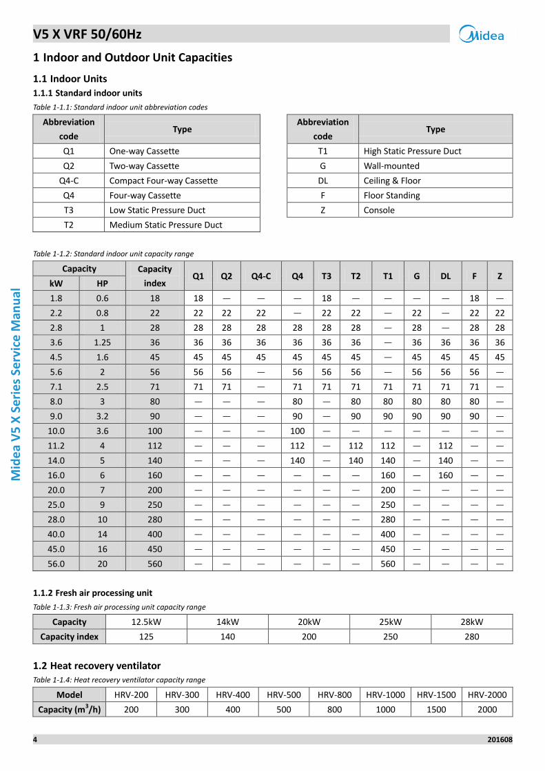
1 Indoor and Outdoor Unit Capacities
1.1 Indoor Units
1.1.1 Standard indoor units
Table 1-1.1: Standard indoor unit abbreviation codes
Abbreviation
code Type
Abbreviation
code Type
Q1 One-way Cassette T1 High Static Pressure Duct
Q2 Two-way Cassette G Wall-mounted
Q4-C Compact Four-way Cassette DL Ceiling & Floor
Q4 Four-way Cassette F Floor Standing
T3 Low Static Pressure Duct Z Console
T2 Medium Static Pressure Duct
Table 1-1.2: Standard indoor unit capacity range
Capacity Capacity
index Q1 Q2 Q4-C Q4 T3 T2 T1 G DL F Z
kW HP
1.8 0.6 18 18 — — — 18 — — — — 18 —
2.2 0.8 22 22 22 22 — 22 22 — 22 — 22 22
2.8 1 28 28 28 28 28 28 28 — 28 — 28 28
3.6 1.25 36 36 36 36 36 36 36 — 36 36 36 36
4.5 1.6 45 45 45 45 45 45 45 — 45 45 45 45
5.6 2 56 56 56 — 56 56 56 — 56 56 56 —
7.1 2.5 71 71 71 — 71 71 71 71 71 71 71 —
8.0 3 80 — — — 80 — 80 80 80 80 80 —
9.0 3.2 90 — — — 90 — 90 90 90 90 90 —
10.0 3.6 100 — — — 100 — — — — — — —
11.2 4 112 — — — 112 — 112 112 — 112 — —
14.0 5 140 — — — 140 — 140 140 — 140 — —
16.0 6 160 — — — — — — 160 — 160 — —
20.0 7 200 — — — — — — 200 — — — —
25.0 9 250 — — — — — — 250 — — — —
28.0 10 280 — — — — — — 280 — — — —
40.0 14 400 — — — — — — 400 — — — —
45.0 16 450 — — — — — — 450 — — — —
56.0 20 560 — — — — — — 560 — — — —
1.1.2 Fresh air processing unit
Table 1-1.3: Fresh air processing unit capacity range
Capacity 12.5kW 14kW 20kW 25kW 28kW
Capacity index 125 140 200 250 280
1.2 Heat recovery ventilator Table 1-1.4: Heat recovery ventilator capacity range
Model HRV-200 HRV-300 HRV-400 HRV-500 HRV-800 HRV-1000 HRV-1500 HRV-2000
Capacity (m3/h) 200 300 400 500 800 1000 1500 2000
V5 X VRF 50/60Hz
201608 5
Part 1
- Ge
ne
ral Info
rmatio
n
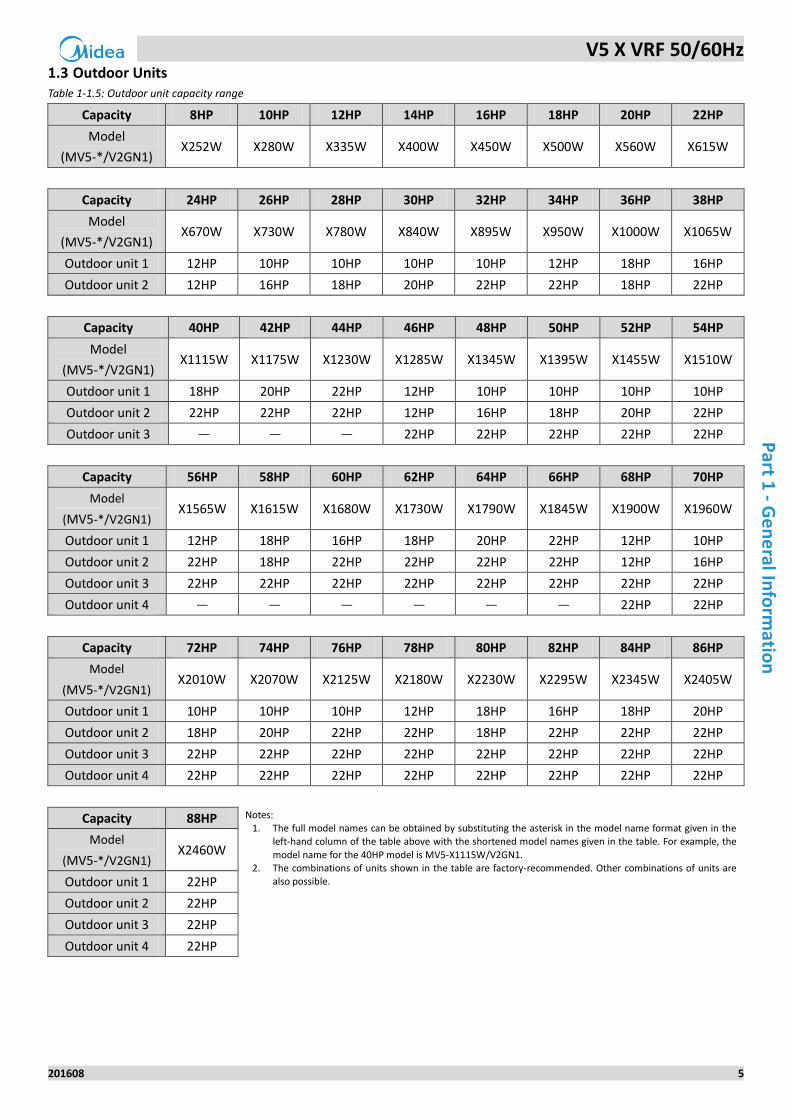
1.3 Outdoor Units Table 1-1.5: Outdoor unit capacity range
Capacity 8HP 10HP 12HP 14HP 16HP 18HP 20HP 22HP
Model
(MV5-*/V2GN1) X252W X280W X335W X400W X450W X500W X560W X615W
Capacity 24HP 26HP 28HP 30HP 32HP 34HP 36HP 38HP
Model
(MV5-*/V2GN1) X670W X730W X780W X840W X895W X950W X1000W X1065W
Outdoor unit 1 12HP 10HP 10HP 10HP 10HP 12HP 18HP 16HP
Outdoor unit 2 12HP 16HP 18HP 20HP 22HP 22HP 18HP 22HP
Capacity 40HP 42HP 44HP 46HP 48HP 50HP 52HP 54HP
Model
(MV5-*/V2GN1) X1115W X1175W X1230W X1285W X1345W X1395W X1455W X1510W
Outdoor unit 1 18HP 20HP 22HP 12HP 10HP 10HP 10HP 10HP
Outdoor unit 2 22HP 22HP 22HP 12HP 16HP 18HP 20HP 22HP
Outdoor unit 3 — — — 22HP 22HP 22HP 22HP 22HP
Capacity 56HP 58HP 60HP 62HP 64HP 66HP 68HP 70HP
Model
(MV5-*/V2GN1) X1565W X1615W X1680W X1730W X1790W X1845W X1900W X1960W
Outdoor unit 1 12HP 18HP 16HP 18HP 20HP 22HP 12HP 10HP
Outdoor unit 2 22HP 18HP 22HP 22HP 22HP 22HP 12HP 16HP
Outdoor unit 3 22HP 22HP 22HP 22HP 22HP 22HP 22HP 22HP
Outdoor unit 4 — — — — — — 22HP 22HP
Capacity 72HP 74HP 76HP 78HP 80HP 82HP 84HP 86HP
Model
(MV5-*/V2GN1) X2010W X2070W X2125W X2180W X2230W X2295W X2345W X2405W
Outdoor unit 1 10HP 10HP 10HP 12HP 18HP 16HP 18HP 20HP
Outdoor unit 2 18HP 20HP 22HP 22HP 18HP 22HP 22HP 22HP
Outdoor unit 3 22HP 22HP 22HP 22HP 22HP 22HP 22HP 22HP
Outdoor unit 4 22HP 22HP 22HP 22HP 22HP 22HP 22HP 22HP
Capacity 88HP Notes: 1. The full model names can be obtained by substituting the asterisk in the model name format given in the
left-hand column of the table above with the shortened model names given in the table. For example, the
model name for the 40HP model is MV5-X1115W/V2GN1. 2. The combinations of units shown in the table are factory-recommended. Other combinations of units are
also possible.
Model
(MV5-*/V2GN1) X2460W
Outdoor unit 1 22HP
Outdoor unit 2 22HP
Outdoor unit 3 22HP
Outdoor unit 4 22HP
V5 X VRF 50/60Hz
6 201608
Mid
ea
V5
X S
eri
es
Serv
ice
Man
ual
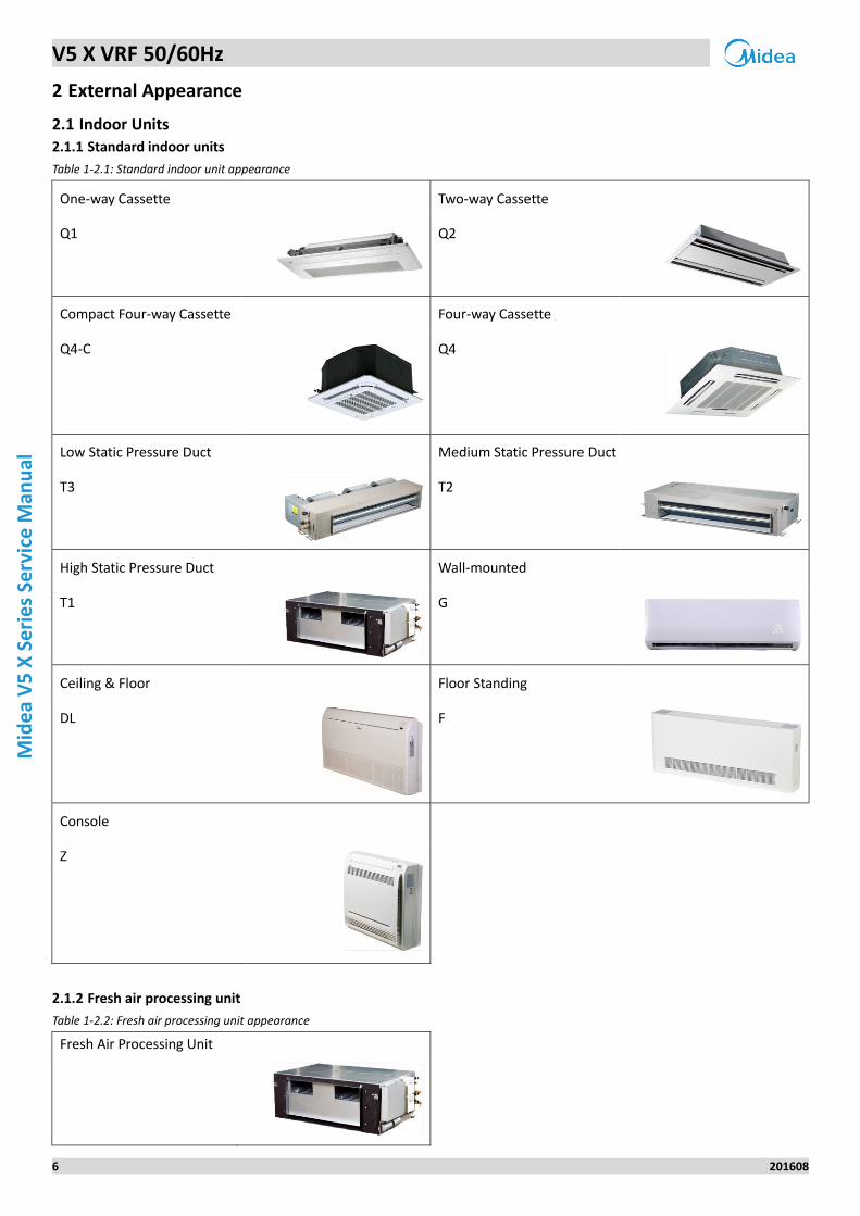
2 External Appearance
2.1 Indoor Units
2.1.1 Standard indoor units
Table 1-2.1: Standard indoor unit appearance
One-way Cassette Two-way Cassette
Q1
Q2
Compact Four-way Cassette Four-way Cassette
Q4-C
Q4
Low Static Pressure Duct Medium Static Pressure Duct
T3
T2
High Static Pressure Duct Wall-mounted
T1
G
Ceiling & Floor Floor Standing
DL
F
Console
Z
2.1.2 Fresh air processing unit
Table 1-2.2: Fresh air processing unit appearance
Fresh Air Processing Unit
V5 X VRF 50/60Hz
201608 7
Part 1
- Ge
ne
ral Info
rmatio
n
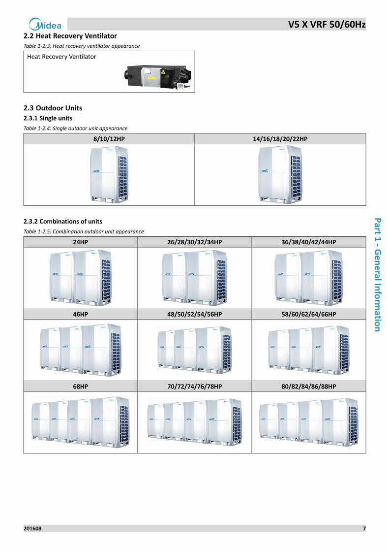
2.2 Heat Recovery Ventilator Table 1-2.3: Heat recovery ventilator appearance
Heat Recovery Ventilator
2.3 Outdoor Units
2.3.1 Single units
Table 1-2.4: Single outdoor unit appearance
8/10/12HP 14/16/18/20/22HP
2.3.2 Combinations of units
Table 1-2.5: Combination outdoor unit appearance
24HP 26/28/30/32/34HP 36/38/40/42/44HP
46HP 48/50/52/54/56HP 58/60/62/64/66HP
68HP 70/72/74/76/78HP 80/82/84/86/88HP
V5 X VRF 50/60Hz
8 201608
Mid
ea
V5
X S
eri
es
Serv
ice
Man
ual
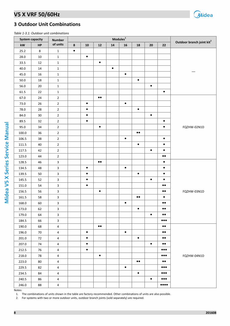
3 Outdoor Unit Combinations
Table 1-3.1: Outdoor unit combinations
System capacity Number of units
Modules1
Outdoor branch joint kit2
kW HP 8 10 12 14 16 18 20 22
25.2 8 1 ●
—
28.0 10 1 ●
33.5 12 1 ●
40.0 14 1 ●
45.0 16 1 ●
50.0 18 1 ●
56.0 20 1 ●
61.5 22 1 ●
67.0 24 2 ●●
FQZHW-02N1D
73.0 26 2 ● ●
78.0 28 2 ● ●
84.0 30 2 ● ●
89.5 32 2 ● ●
95.0 34 2 ● ●
100.0 36 2 ●●
106.5 38 2 ● ●
111.5 40 2 ● ●
117.5 42 2 ● ●
123.0 44 2 ●●
128.5 46 3 ●● ●
FQZHW-03N1D
134.5 48 3 ● ● ●
139.5 50 3 ● ● ●
145.5 52 3 ● ● ●
151.0 54 3 ● ●●
156.5 56 3 ● ●●
161.5 58 3 ●● ●
168.0 60 3 ● ●●
173.0 62 3 ● ●●
179.0 64 3 ● ●●
184.5 66 3 ●●●
190.0 68 4 ●● ●●
FQZHW-04N1D
196.0 70 4 ● ● ●●
201.0 72 4 ● ● ●●
207.0 74 4 ● ● ●●
212.5 76 4 ● ●●●
218.0 78 4 ● ●●●
223.0 80 4 ●● ●●
229.5 82 4 ● ●●●
234.5 84 4 ● ●●●
240.5 86 4 ● ●●●
246.0 88 4 ●●●●
Notes: 1. The combinations of units shown in the table are factory-recommended. Other combinations of units are also possible.
2. For systems with two or more outdoor units, outdoor branch joints (sold separately) are required.
V5 X VRF 50/60Hz
201608 9
Part 1
- Ge
ne
ral Info
rmatio
n
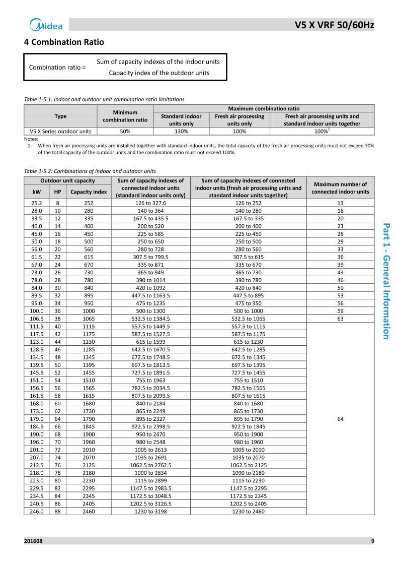
4 Combination Ratio
Table 1-5.1: Indoor and outdoor unit combination ratio limitations
Type Minimum
combination ratio
Maximum combination ratio
Standard indoor units only
Fresh air processing units only
Fresh air processing units and standard indoor units together
V5 X Series outdoor units 50% 130% 100% 100%1
Notes: 1. When fresh air processing units are installed together with standard indoor units, the total capacity of the fresh air processing units must not exceed 30%
of the total capacity of the outdoor units and the combination ratio must not exceed 100%.
Table 1-5.2: Combinations of Indoor and outdoor units
Outdoor unit capacity Sum of capacity indexes of connected indoor units
(standard indoor units only)
Sum of capacity indexes of connected indoor units (fresh air processing units and
standard indoor units together)
Maximum number of connected indoor units kW HP Capacity index
25.2 8 252 126 to 327.6 126 to 252 13
28.0 10 280 140 to 364 140 to 280 16
33.5 12 335 167.5 to 435.5 167.5 to 335 20
40.0 14 400 200 to 520 200 to 400 23
45.0 16 450 225 to 585 225 to 450 26
50.0 18 500 250 to 650 250 to 500 29
56.0 20 560 280 to 728 280 to 560 33
61.5 22 615 307.5 to 799.5 307.5 to 615 36
67.0 24 670 335 to 871 335 to 670 39
73.0 26 730 365 to 949 365 to 730 43
78.0 28 780 390 to 1014 390 to 780 46
84.0 30 840 420 to 1092 420 to 840 50
89.5 32 895 447.5 to 1163.5 447.5 to 895 53
95.0 34 950 475 to 1235 475 to 950 56
100.0 36 1000 500 to 1300 500 to 1000 59
106.5 38 1065 532.5 to 1384.5 532.5 to 1065 63
111.5 40 1115 557.5 to 1449.5 557.5 to 1115
64
117.5 42 1175 587.5 to 1527.5 587.5 to 1175
123.0 44 1230 615 to 1599 615 to 1230
128.5 46 1285 642.5 to 1670.5 642.5 to 1285
134.5 48 1345 672.5 to 1748.5 672.5 to 1345
139.5 50 1395 697.5 to 1813.5 697.5 to 1395
145.5 52 1455 727.5 to 1891.5 727.5 to 1455
151.0 54 1510 755 to 1963 755 to 1510
156.5 56 1565 782.5 to 2034.5 782.5 to 1565
161.5 58 1615 807.5 to 2099.5 807.5 to 1615
168.0 60 1680 840 to 2184 840 to 1680
173.0 62 1730 865 to 2249 865 to 1730
179.0 64 1790 895 to 2327 895 to 1790
184.5 66 1845 922.5 to 2398.5 922.5 to 1845
190.0 68 1900 950 to 2470 950 to 1900
196.0 70 1960 980 to 2548 980 to 1960
201.0 72 2010 1005 to 2613 1005 to 2010
207.0 74 2070 1035 to 2691 1035 to 2070
212.5 76 2125 1062.5 to 2762.5 1062.5 to 2125
218.0 78 2180 1090 to 2834 1090 to 2180
223.0 80 2230 1115 to 2899 1115 to 2230
229.5 82 2295 1147.5 to 2983.5 1147.5 to 2295
234.5 84 2345 1172.5 to 3048.5 1172.5 to 2345
240.5 86 2405 1202.5 to 3126.5 1202.5 to 2405
246.0 88 2460 1230 to 3198 1230 to 2460
Combination ratio = Sum of capacity indexes of the indoor units
Capacity index of the outdoor units

V5 X VRF 50/60Hz
10 201608
Mid
ea
V5
X S
eri
es
Serv
ice
Man
ual
V5 X VRF 50/60Hz
201608 11
Part 2
- Co
mp
on
en
t Layou
t and
Refrige
rant C
ircuits
Part 2
Component Layout and
Refrigerant Circuits
1 Layout of Functional Components ....................................................... 12
2 Piping Diagrams .................................................................................. 14
3 Refrigerant Flow Diagrams .................................................................. 16
V5 X VRF 50/60Hz
12 201608
Mid
ea
V5
X S
eri
es
Serv
ice
Man
ual
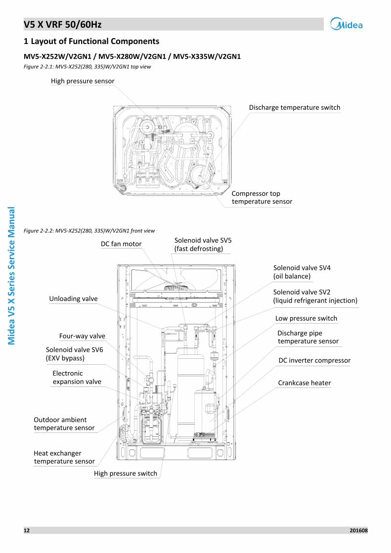
1 Layout of Functional Components
MV5-X252W/V2GN1 / MV5-X280W/V2GN1 / MV5-X335W/V2GN1 Figure 2-2.1: MV5-X252(280, 335)W/V2GN1 top view
High pressure sensor
Discharge temperature switch
Compressor toptemperature sensor
Figure 2-2.2: MV5-X252(280, 335)W/V2GN1 front view
DC fan motor Solenoid valve SV5(fast defrosting)
Solenoid valve SV4(oil balance)
Solenoid valve SV2(liquid refrigerant injection)
Low pressure switch
Discharge pipetemperature sensor
DC inverter compressor
Unloading valve
Four-way valve
Solenoid valve SV6(EXV bypass)
Heat exchangertemperature sensor
High pressure switch
Crankcase heater
Outdoor ambienttemperature sensor
Electronicexpansion valve
V5 X VRF 50/60Hz
201608 13
Part 2
- Co
mp
on
en
t Layou
t and
Refrige
rant C
ircuits
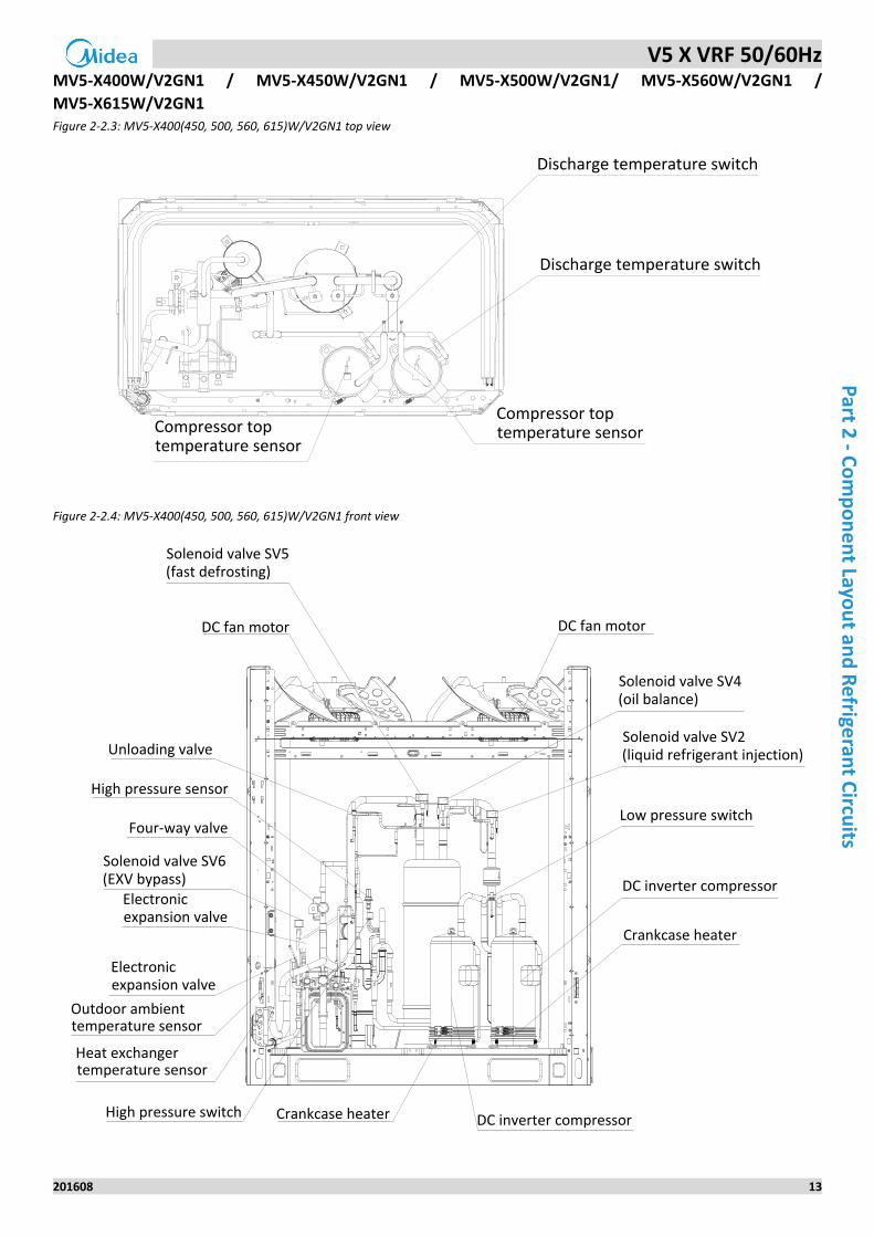
MV5-X400W/V2GN1 / MV5-X450W/V2GN1 / MV5-X500W/V2GN1/ MV5-X560W/V2GN1 /
MV5-X615W/V2GN1 Figure 2-2.3: MV5-X400(450, 500, 560, 615)W/V2GN1 top view
Compressor toptemperature sensorCompressor top
temperature sensor
Discharge temperature switch
Discharge temperature switch
Figure 2-2.4: MV5-X400(450, 500, 560, 615)W/V2GN1 front view
Solenoid valve SV5(fast defrosting)
DC fan motor DC fan motor
Solenoid valve SV4(oil balance)
Solenoid valve SV2(liquid refrigerant injection)
Low pressure switch
Crankcase heater
DC inverter compressorCrankcase heaterHigh pressure switch
DC inverter compressor
Heat exchangertemperature sensor
Outdoor ambienttemperature sensor
Electronicexpansion valve
Solenoid valve SV6(EXV bypass)
Four-way valve
High pressure sensor
Unloading valve
Electronicexpansion valve
V5 X VRF 50/60Hz
14 201608
Mid
ea
V5
X S
eri
es
Serv
ice
Man
ual
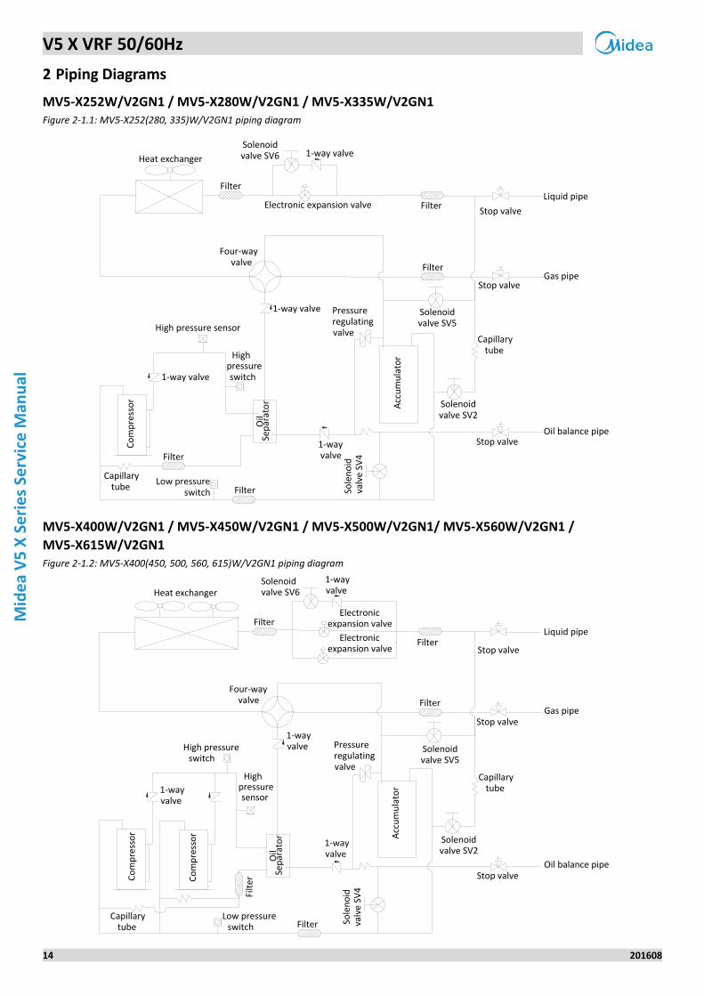
2 Piping Diagrams
MV5-X252W/V2GN1 / MV5-X280W/V2GN1 / MV5-X335W/V2GN1 Figure 2-1.1: MV5-X252(280, 335)W/V2GN1 piping diagram
Filter
Four-way valve
High pressure sensor
Pressureregulatingvalve
Co
mp
ress
or
Oil
Sep
arat
or Acc
um
ula
tor
Solenoidvalve SV2
Electronic expansion valve
Highpressure switch
Heat exchanger1-way valve
1-way valve
1-way valve
1-wayvalve
Filter
Sole
no
idva
lve
SV
4
Solenoidvalve SV6
Solenoidvalve SV5
Stop valve
Stop valve
Stop valve
Capillary tube
Liquid pipe
Gas pipe
Oil balance pipe
MV5-X400W/V2GN1 / MV5-X450W/V2GN1 / MV5-X500W/V2GN1/ MV5-X560W/V2GN1 /
MV5-X615W/V2GN1 Figure 2-1.2: MV5-X400(450, 500, 560, 615)W/V2GN1 piping diagram
Solenoidvalve SV2
Heat exchanger
Four-wayvalve
Low pressure switch
High pressure switch
Pressureregulatingvalve
Co
mp
ress
or
Co
mp
ress
or
Oil
Sep
arat
or A
ccu
mu
lato
r
Capillary tube
Highpressure sensor
1-wayvalve
FilterStop valve
Stop valve
Stop valve
1-wayvalve
1-wayvalve
Solenoidvalve SV5
Solenoidvalve SV6
Sole
no
idva
lve
SV4
Capillary tube
Filt
er
Electronicexpansion valve
Electronicexpansion valve
Liquid pipe
Gas pipe
Oil balance pipe
V5 X VRF 50/60Hz
201608 15
Part 2
- Co
mp
on
en
t Layou
t and
Refrige
rant C
ircuits
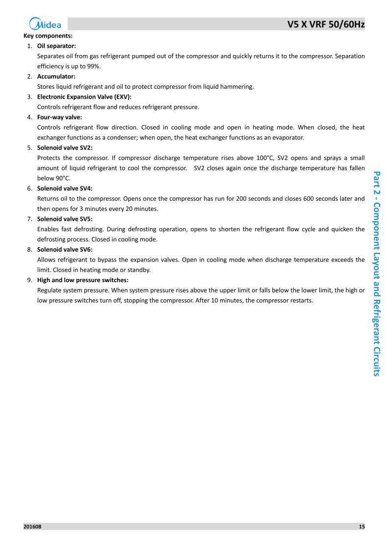
Key components:
1. Oil separator:
Separates oil from gas refrigerant pumped out of the compressor and quickly returns it to the compressor. Separation
efficiency is up to 99%.
2. Accumulator:
Stores liquid refrigerant and oil to protect compressor from liquid hammering.
3. Electronic Expansion Valve (EXV):
Controls refrigerant flow and reduces refrigerant pressure.
4. Four-way valve:
Controls refrigerant flow direction. Closed in cooling mode and open in heating mode. When closed, the heat
exchanger functions as a condenser; when open, the heat exchanger functions as an evaporator.
5. Solenoid valve SV2:
Protects the compressor. If compressor discharge temperature rises above 100°C, SV2 opens and sprays a small
amount of liquid refrigerant to cool the compressor. SV2 closes again once the discharge temperature has fallen
below 90°C.
6. Solenoid valve SV4:
Returns oil to the compressor. Opens once the compressor has run for 200 seconds and closes 600 seconds later and
then opens for 3 minutes every 20 minutes.
7. Solenoid valve SV5:
Enables fast defrosting. During defrosting operation, opens to shorten the refrigerant flow cycle and quicken the
defrosting process. Closed in cooling mode.
8. Solenoid valve SV6:
Allows refrigerant to bypass the expansion valves. Open in cooling mode when discharge temperature exceeds the
limit. Closed in heating mode or standby.
9. High and low pressure switches:
Regulate system pressure. When system pressure rises above the upper limit or falls below the lower limit, the high or
low pressure switches turn off, stopping the compressor. After 10 minutes, the compressor restarts.
V5 X VRF 50/60Hz
16 201608
Mid
ea
V5
X S
eri
es
Serv
ice
Man
ual
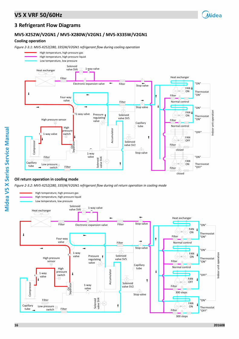
3 Refrigerant Flow Diagrams
MV5-X252W/V2GN1 / MV5-X280W/V2GN1 / MV5-X335W/V2GN1
Cooling operation
Figure 2-3.1: MV5-X252(280, 335)W/V2GN1 refrigerant flow during cooling operation
M
M
M
M
High temperature, high pressure gas
High temperature, high pressure liquid
Low temperature, low pressure
FANON
FANON
FANOFF
FANON
Normal control
Filter
Filter
Normal control
Four-way valve
High pressure sensor
Pressureregulatingvalve
Co
mp
ress
or
Oil
Sep
arat
or Acc
um
ula
tor
Solenoidvalve SV2
Electronic expansion valve
closed
Highpressure switch
Heat exchanger
Heat exchanger
1-way valve
1-way valve
1-way valve
1-wayvalve
Filter
Sole
no
idva
lve
SV4
Solenoidvalve SV6
Solenoidvalve SV5
Filter
Filter
Filter
Stop valve
Stop valve
Stop valve
Capillary tube
"ON"
"ON"
"OFF"
"ON"
Ind
oo
r u
nit
op
erat
ion
closed
Oil return operation in cooling mode
Figure 2-3.2: MV5-X252(280, 335)W/V2GN1 refrigerant flow during oil return operation in cooling mode
M
M
M
M
1-wayvalve
High temperature, high pressure gas
High temperature, high pressure liquid
Low temperature, low pressure
Heat exchanger
Heat exchanger
High pressuresensor
Low pressure switch
Co
mp
ress
or
Pressureregulatingvalve
Oil
Sep
arat
or Acc
um
ula
tor
Filter
Filter
Filter
Filter
FANON
Normal control
Normal control
300 steps
Electronic expansion valve
Four-way valve
Filter
Highpressure switch
"ON"
"ON"
"OFF"
"ON"
Filter
Stop valve
Ind
oo
r u
nit
op
erat
ion
Filter
Capillary tube
Stop valve
Stop valve
Solenoidvalve SV2
Sole
no
idva
lve
SV4
Solenoidvalve SV6
Solenoidvalve SV5
1-wayvalve
1-wayvalve
1-way valve
Filter
Filter
FANON
FANOFF
FANON
300 steps
V5 X VRF 50/60Hz
201608 17
Part 2
- Co
mp
on
en
t Layou
t and
Refrige
rant C
ircuits
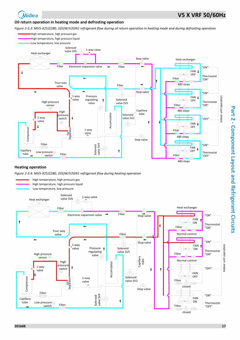
Oil return operation in heating mode and defrosting operation
Figure 2-3.3: MV5-X252(280, 335)W/V2GN1 refrigerant flow during oil return operation in heating mode and during defrosting operation
M
M
M
M
High temperature, high pressure gas
High temperature, high pressure liquid
Low temperature, low pressure
FANOFF
Heat exchanger
FANOFF
FANOFF
FANOFF
Heat exchanger
Highpressure switch
High pressuresensor
Low pressure switch
Co
mp
ress
or
Oil
Sep
arat
or A
ccu
mu
lato
r
Electronic expansion valve Filter
480 steps
Filter
"ON"
"ON"
"OFF"
"ON"
Filter
Stop valve
Ind
oo
r u
nit
op
erat
ion
Filter
Sole
no
idva
lve
SV4
Stop valve
Stop valve
Capillary tube
Filter
Filter
Filter
Solenoidvalve SV2
1-way valve
Solenoidvalve SV5
480 steps
480 steps
480 steps
Filter
Filter
Heating operation
Figure 2-3.4: MV5-X252(280, 335)W/V2GN1 refrigerant flow during heating operation
M
M
M
M
High temperature, high pressure gas
High temperature, high pressure liquid
Low temperature, low pressure
FANON
FANON
FANOFF
FANON
Filter
Normal control
Filter
Normal controlFour-way valve
Low pressureswitch
High pressuresensor
Pressureregulating
valve
Co
mp
ress
or
Oil
Sep
arat
or A
ccu
mu
lato
r
Electronic expansion valve
Highpressure
switch
Heat exchanger
closed
Heat exchanger
Solenoidvalve SV2
Sole
no
idva
lve
SV4
Solenoidvalve SV6
Solenoidvalve SV5
Stop valve
Stop valve
Stop valve
1-way valve
1-wayvalve
1-wayvalve
Filter
Filter
Filter
Filter
"ON"
"ON"
"OFF"
"ON"
Ind
oo
r u
nit
op
erat
ion
Capillary tube
Filter
Filter
closed
V5 X VRF 50/60Hz
18 201608
Mid
ea
V5
X S
eri
es
Serv
ice
Man
ual
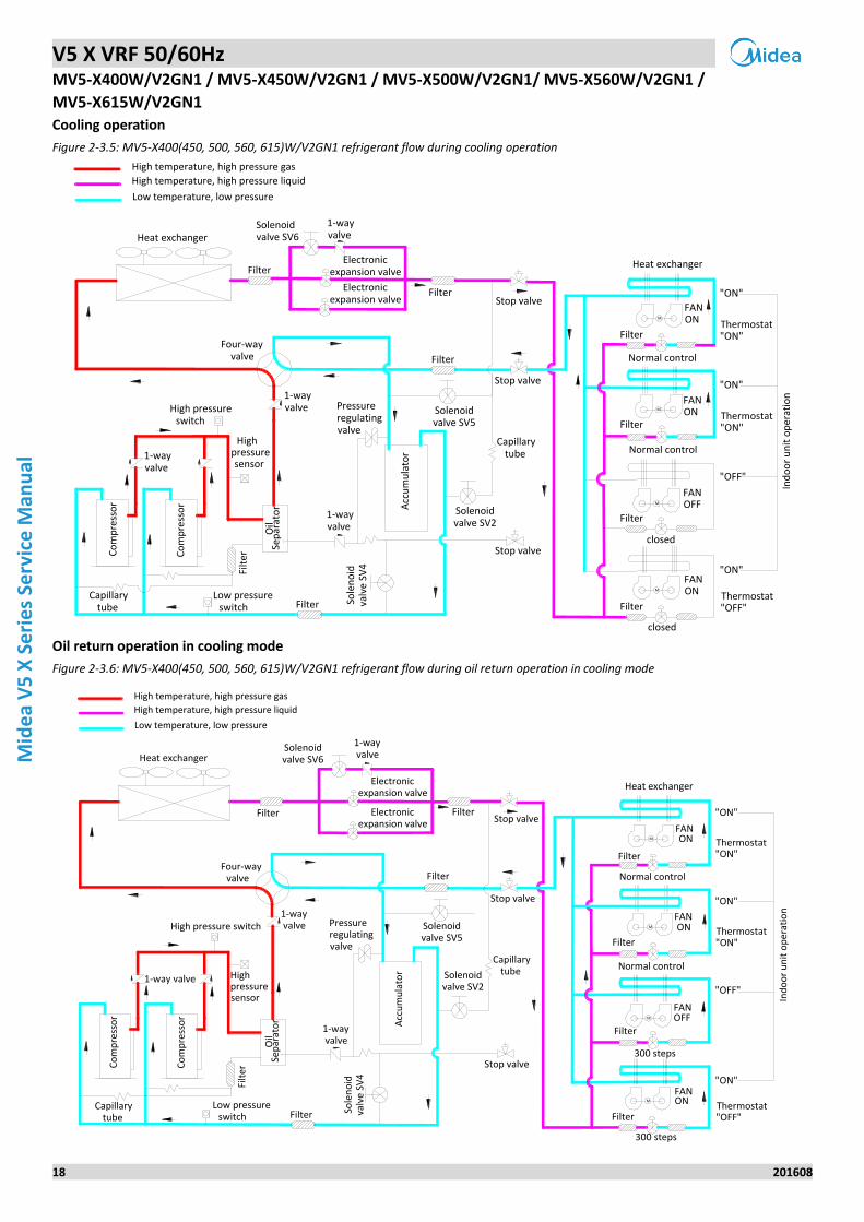
MV5-X400W/V2GN1 / MV5-X450W/V2GN1 / MV5-X500W/V2GN1/ MV5-X560W/V2GN1 /
MV5-X615W/V2GN1
Cooling operation
Figure 2-3.5: MV5-X400(450, 500, 560, 615)W/V2GN1 refrigerant flow during cooling operation
Solenoidvalve SV2
M
M
M
M
High temperature, high pressure gas
High temperature, high pressure liquid
Low temperature, low pressure
FANON
FANOFF
FANON
Heat exchanger
Heat exchanger
FANON
Filter
Normal control
Normal control
Four-wayvalve
Low pressure switch
High pressure switch
Pressureregulatingvalve
Co
mp
ress
or
Co
mp
ress
or
Oil
Sep
arat
or A
ccu
mu
lato
r
Capillary tube
closed
Highpressure sensor
1-wayvalve
Filter "ON"
"ON"
"OFF"
"ON"
Filter
Filter
Filter
Stop valve
Stop valve
Stop valve
1-wayvalve
1-wayvalve
Solenoidvalve SV5
Solenoidvalve SV6
Sole
no
idva
lve
SV4
Ind
oo
r u
nit
op
erat
ion
Capillary tube
Filt
er
Electronicexpansion valve
Electronicexpansion valve
closed
Oil return operation in cooling mode
Figure 2-3.6: MV5-X400(450, 500, 560, 615)W/V2GN1 refrigerant flow during oil return operation in cooling mode
Four-way valve
M
M
M
M
High temperature, high pressure gas
High temperature, high pressure liquid
Low temperature, low pressure
FAN
FAN
FAN
Heat exchanger
Heat exchanger
FAN
ON
ON
OFF
ON
Filter
Filter
300 steps
Normal control
Normal control
Low pressure switch
Highpressuresensor
High pressure switch Pressureregulatingvalve
Co
mp
ress
or
Co
mp
ress
or
Oil
Sep
arat
or Acc
um
ula
tor
Electronicexpansion valve
"ON"
"ON"
"OFF"
"ON"
Filter
Stop valve
Ind
oo
r u
nit
op
erat
ion
FilterCapillary tube
Stop valve
Stop valve
Filter
Sole
no
idva
lve
SV4
Solenoidvalve SV2
Solenoidvalve SV5 Filter
Filter
Filter
1-wayvalve
Solenoidvalve SV6
Filt
er
Electronicexpansion valve
300 steps
V5 X VRF 50/60Hz
201608 19
Part 2
- Co
mp
on
en
t Layou
t and
Refrige
rant C
ircuits
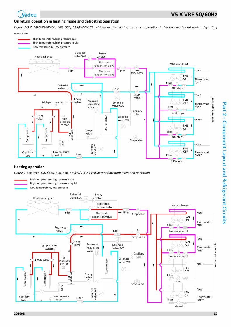
Oil return operation in heating mode and defrosting operation
Figure 2-3.7: MV5-X400(450, 500, 560, 615)W/V2GN1 refrigerant flow during oil return operation in heating mode and during defrosting
operation
M
M
M
M
High temperature, high pressure gas
High temperature, high pressure liquid
Low temperature, low pressure
FANOFF
FANOFF
FANOFF
Heat exchanger
Heat exchanger
FANOFF
FilterFour-way valve
Low pressure switch
High pressure switch
Highpressure sensor
Pressureregulatingvalve
Co
mp
ress
or
Co
mp
ress
or
Oil
Sep
arat
or Acc
um
ula
tor
Electronicexpansion valve
FilterFilter "ON"
"ON"
"OFF"
"ON"
Stop valve
Ind
oo
r u
nit
op
erat
ion
Filter
Filter
Filter
Filter
Filter
Stop valve
Stopvalve
Sole
no
idva
lve
SV4
Solenoidvalve SV2
Solenoidvalve SV5
480 steps
Solenoidvalve SV6
1-wayvalve
Capillary tube
Filt
erElectronic
expansion valve
480 steps
480 steps
480 steps
Heating operation
Figure 2-3.8: MV5-X400(450, 500, 560, 615)W/V2GN1 refrigerant flow during heating operation
M
M
M
M
High temperature, high pressure gas
High temperature, high pressure liquid
Low temperature, low pressure
FANON
FANOFF
FANON
1-way value
Heat exchanger
Heat exchanger
Filter
Normal control
Filter
Normal control
Four-way valve
Low pressure switch
High pressure switch
Pressureregulatingvalve
Co
mp
ress
or
Electronicexpansion valve
Highpressure sensor
closed
Co
mp
ress
or
Oil
Sep
arat
or Acc
um
ula
tor
FANON
"ON"
"ON"
"OFF"
"ON"
Filter
Stop valve
Ind
oo
r u
nit
op
erat
ion
Stop valve
Stop valve
Filter
Filter
1-wayvalve
Filter
Filter
Filter
1-wayvalve
Solenoidvalve SV2
Solenoidvalve SV5
Solenoidvalve SV6
Sole
no
idva
lve
SV4
1-wayvalve
Capillary tube
Filt
er
Electronicexpansion valve
closed
V5 X VRF 50/60Hz
20 201608
Mid
ea
V5
X S
eri
es
Serv
ice
Man
ual
V5 X VRF 50/60Hz
201608 21
Part 3
- Co
ntro
l
Part 3
Control
1 General Control Scheme Flowchart ...................................................... 22
2 Stop Operation .................................................................................... 23
3 Standby Control ................................................................................... 23
4 Startup Control .................................................................................... 24
5 Normal Operation Control ................................................................... 25
6 Protection Control ............................................................................... 30
7 Special Control ..................................................................................... 32
V5 X VRF 50/60Hz
22 201608
Mid
ea
V5
X S
eri
es
Serv
ice
Man
ual
1 General Control Scheme Flowchart
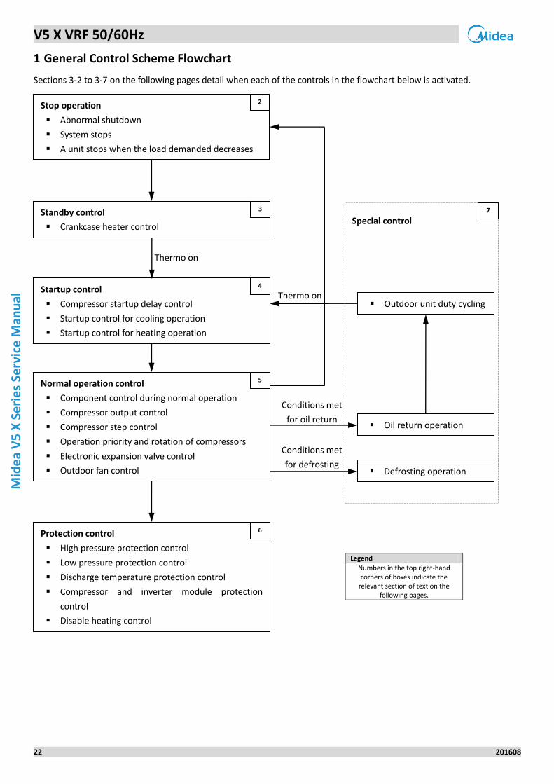
Sections 3-2 to 3-7 on the following pages detail when each of the controls in the flowchart below is activated.
Legend
Numbers in the top right-hand corners of boxes indicate the
relevant section of text on the following pages.
Conditions met
for oil return
Conditions met
for defrosting
Thermo on
Special control
Outdoor unit duty cycling
Oil return operation
Defrosting operation
7
Stop operation
Abnormal shutdown
System stops
A unit stops when the load demanded decreases
2
Standby control
Crankcase heater control
3
Startup control
Compressor startup delay control
Startup control for cooling operation
Startup control for heating operation
4
Thermo on
Normal operation control
Component control during normal operation
Compressor output control
Compressor step control
Operation priority and rotation of compressors
Electronic expansion valve control
Outdoor fan control
5
Protection control
High pressure protection control
Low pressure protection control
Discharge temperature protection control
Compressor and inverter module protection
control
Disable heating control
6
V5 X VRF 50/60Hz
201608 23
Part 3
- Co
ntro
l
2 Stop Operation
The stop operation occurs for one of the three following reasons:
1. Abnormal shutdown: in order to protect the compressors, if an abnormal state occurs the system makes a 'stop with
thermo off' operation and an error code is displayed on the digital display.
2. The system stops when the set temperature has been reached.
3. A unit stops when the load demanded by the indoor units decreases and can be handled by fewer outdoor units.
When a unit stops because the load demanded by the indoor units has decreased and can be handled by fewer outdoor
units, the unit's four-way valve remains on until the load demanded by the indoor units increases and the unit is required
to operate. When the whole system stops, all the units' four-way valves turn off.
3 Standby Control
3.1 Crankcase Heater Control
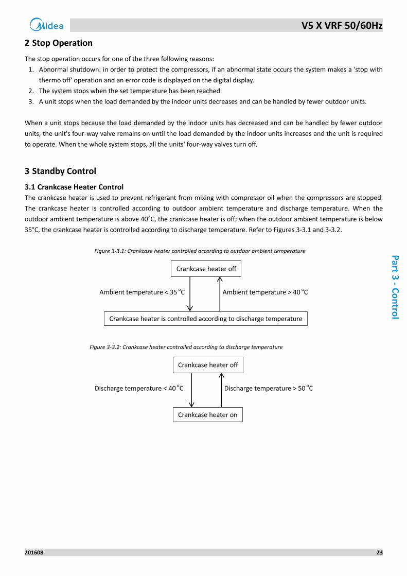
The crankcase heater is used to prevent refrigerant from mixing with compressor oil when the compressors are stopped.
The crankcase heater is controlled according to outdoor ambient temperature and discharge temperature. When the
outdoor ambient temperature is above 40°C, the crankcase heater is off; when the outdoor ambient temperature is below
35°C, the crankcase heater is controlled according to discharge temperature. Refer to Figures 3-3.1 and 3-3.2.
Figure 3-3.1: Crankcase heater controlled according to outdoor ambient temperature
Figure 3-3.2: Crankcase heater controlled according to discharge temperature
Ambient temperature < 35 oC Ambient temperature > 40 oC
Crankcase heater off
Crankcase heater is controlled according to discharge temperature
Discharge temperature < 40 oC Discharge temperature > 50 oC
Crankcase heater off
Crankcase heater on
V5 X VRF 50/60Hz
24 201608
Mid
ea
V5
X S
eri
es
Serv
ice
Man
ual
4 Startup Control
4.1 Compressor Startup Delay Control
In initial startup control, compressor startup is delayed for 12 minutes in order to let the master unit search for the indoor
units’ addresses. In restart control (except in oil return operation and defrosting operation), compressor startup is delayed
such that a minimum of 7 minutes has elapsed since the compressor stopped, in order to prevent frequent compressor
on/off and to equalize the pressure within the refrigerant system.
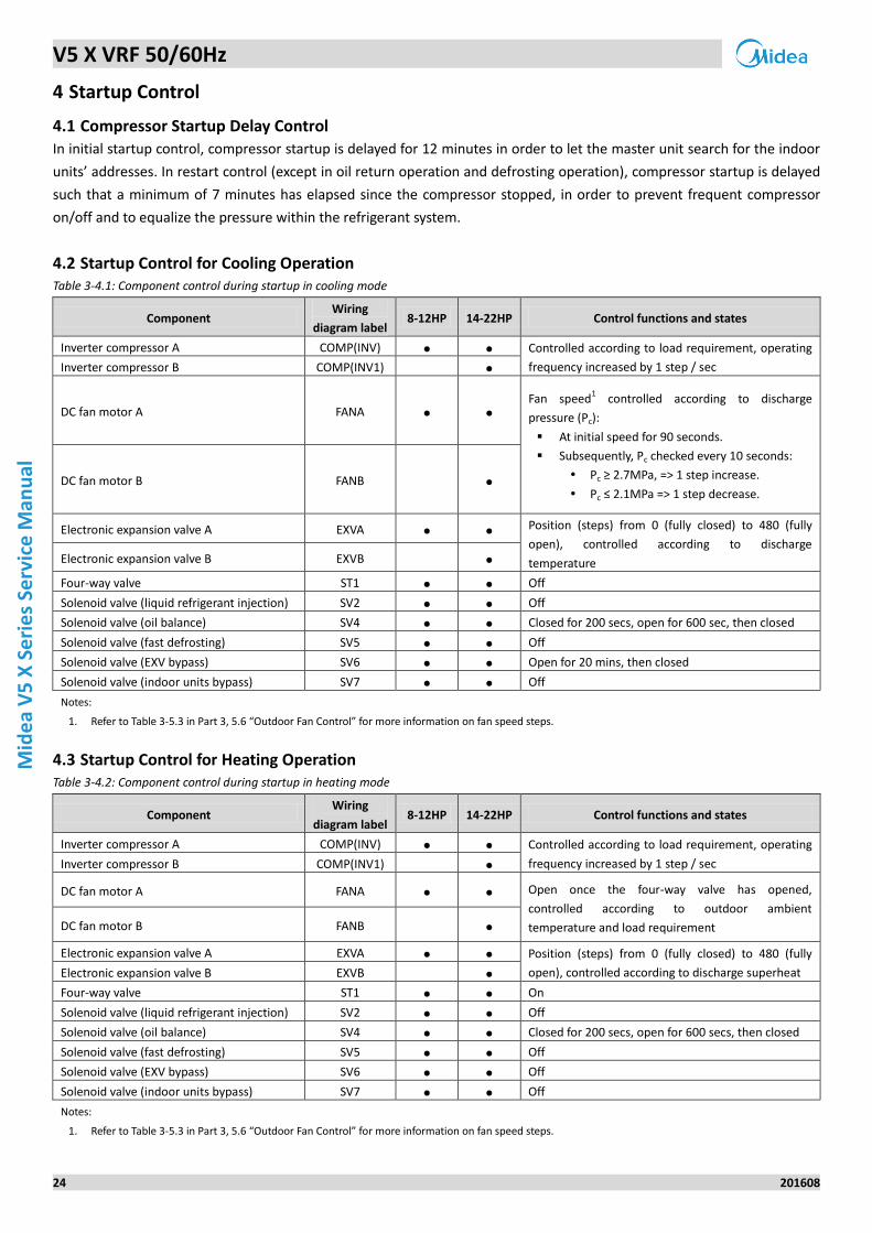
4.2 Startup Control for Cooling Operation Table 3-4.1: Component control during startup in cooling mode
Component Wiring
diagram label 8-12HP 14-22HP Control functions and states
Inverter compressor A COMP(INV) ● ● Controlled according to load requirement, operating
frequency increased by 1 step / sec Inverter compressor B COMP(INV1) ●
DC fan motor A FANA ● ●
Fan speed1 controlled according to discharge
pressure (Pc):
At initial speed for 90 seconds.
Subsequently, Pc checked every 10 seconds:
Pc ≥ 2.7MPa, => 1 step increase.
Pc ≤ 2.1MPa => 1 step decrease. DC fan motor B FANB ●
Electronic expansion valve A EXVA ● ● Position (steps) from 0 (fully closed) to 480 (fully
open), controlled according to discharge
temperature Electronic expansion valve B EXVB ●
Four-way valve ST1 ● ● Off
Solenoid valve (liquid refrigerant injection) SV2 ● ● Off
Solenoid valve (oil balance) SV4 ● ● Closed for 200 secs, open for 600 sec, then closed
Solenoid valve (fast defrosting) SV5 ● ● Off
Solenoid valve (EXV bypass) SV6 ● ● Open for 20 mins, then closed
Solenoid valve (indoor units bypass) SV7 ● ● Off
Notes:
1. Refer to Table 3-5.3 in Part 3, 5.6 “Outdoor Fan Control” for more information on fan speed steps.
4.3 Startup Control for Heating Operation Table 3-4.2: Component control during startup in heating mode
Component Wiring
diagram label 8-12HP 14-22HP Control functions and states
Inverter compressor A COMP(INV) ● ● Controlled according to load requirement, operating
frequency increased by 1 step / sec Inverter compressor B COMP(INV1) ●
DC fan motor A FANA ● ● Open once the four-way valve has opened,
controlled according to outdoor ambient
temperature and load requirement DC fan motor B FANB ●
Electronic expansion valve A EXVA ● ● Position (steps) from 0 (fully closed) to 480 (fully
open), controlled according to discharge superheat Electronic expansion valve B EXVB ●
Four-way valve ST1 ● ● On
Solenoid valve (liquid refrigerant injection) SV2 ● ● Off
Solenoid valve (oil balance) SV4 ● ● Closed for 200 secs, open for 600 secs, then closed
Solenoid valve (fast defrosting) SV5 ● ● Off
Solenoid valve (EXV bypass) SV6 ● ● Off
Solenoid valve (indoor units bypass) SV7 ● ● Off
Notes:
1. Refer to Table 3-5.3 in Part 3, 5.6 “Outdoor Fan Control” for more information on fan speed steps.
V5 X VRF 50/60Hz
201608 25
Part 3
- Co
ntro
l
5 Normal Operation Control
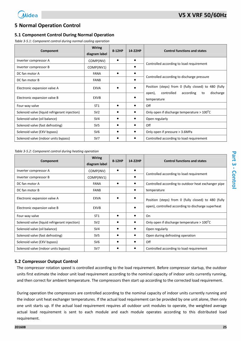
5.1 Component Control During Normal Operation Table 3-5.1: Component control during normal cooling operation
Component Wiring
diagram label 8-12HP 14-22HP Control functions and states
Inverter compressor A COMP(INV) ● ●
Controlled according to load requirement Inverter compressor B COMP(INV1) ●
DC fan motor A FANA ● ●
Controlled according to discharge pressure DC fan motor B FANB ●
Electronic expansion valve A EXVA ● ● Position (steps) from 0 (fully closed) to 480 (fully
open), controlled according to discharge
temperature Electronic expansion valve B EXVB ●
Four-way valve ST1 ● ● Off
Solenoid valve (liquid refrigerant injection) SV2 ● ● Only open if discharge temperature > 100oC
Solenoid valve (oil balance) SV4 ● ● Open regularly
Solenoid valve (fast defrosting) SV5 ● ● Off
Solenoid valve (EXV bypass) SV6 ● ● Only open if pressure > 3.6MPa
Solenoid valve (indoor units bypass) SV7 ● ● Controlled according to load requirement
Table 3-5.2: Component control during heating operation
Component Wiring
diagram label 8-12HP 14-22HP Control functions and states
Inverter compressor A COMP(INV) ● ●
Controlled according to load requirement Inverter compressor B COMP(INV1) ●
DC fan motor A FANA ● ● Controlled according to outdoor heat exchanger pipe
temperature DC fan motor B FANB ●
Electronic expansion valve A EXVA ● ● Position (steps) from 0 (fully closed) to 480 (fully
open), controlled according to discharge superheat Electronic expansion valve B EXVB ●
Four-way valve ST1 ● ● On
Solenoid valve (liquid refrigerant injection) SV2 ● ● Only open if discharge temperature > 100oC
Solenoid valve (oil balance) SV4 ● ● Open regularly
Solenoid valve (fast defrosting) SV5 ● ● Open during defrosting operation
Solenoid valve (EXV bypass) SV6 ● ● Off
Solenoid valve (indoor units bypass) SV7 ● ● Controlled according to load requirement
5.2 Compressor Output Control
The compressor rotation speed is controlled according to the load requirement. Before compressor startup, the outdoor
units first estimate the indoor unit load requirement according to the nominal capacity of indoor units currently running,
and then correct for ambient temperature. The compressors then start up according to the corrected load requirement.
During operation the compressors are controlled according to the nominal capacity of indoor units currently running and
the indoor unit heat exchanger temperatures. If the actual load requirement can be provided by one unit alone, then only
one unit starts up. If the actual load requirement requires all outdoor unit modules to operate, the weighted average
actual load requirement is sent to each module and each module operates according to this distributed load
requirement.
V5 X VRF 50/60Hz
26 201608
Mid
ea
V5
X S
eri
es
Serv
ice
Man
ual
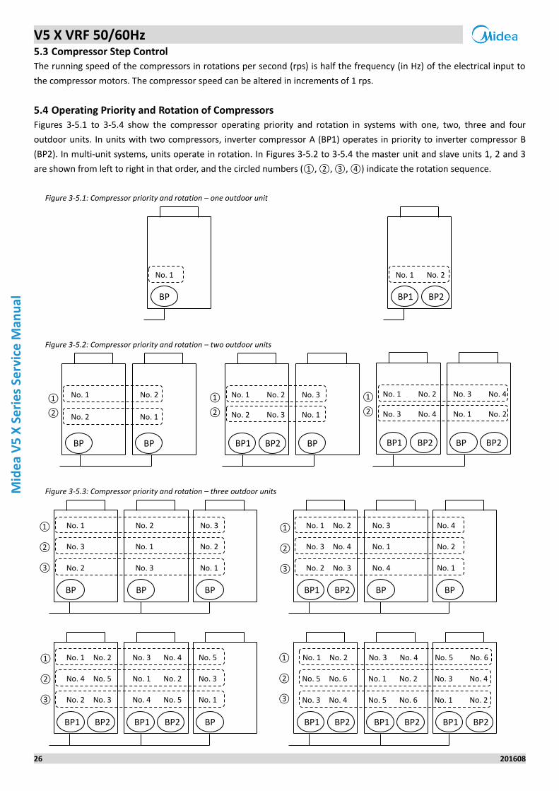
5.3 Compressor Step Control
The running speed of the compressors in rotations per second (rps) is half the frequency (in Hz) of the electrical input to
the compressor motors. The compressor speed can be altered in increments of 1 rps.
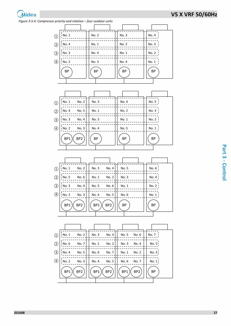
5.4 Operating Priority and Rotation of Compressors
Figures 3-5.1 to 3-5.4 show the compressor operating priority and rotation in systems with one, two, three and four
outdoor units. In units with two compressors, inverter compressor A (BP1) operates in priority to inverter compressor B
(BP2). In multi-unit systems, units operate in rotation. In Figures 3-5.2 to 3-5.4 the master unit and slave units 1, 2 and 3
are shown from left to right in that order, and the circled numbers (①, ②, ③, ④) indicate the rotation sequence.
Figure 3-5.1: Compressor priority and rotation – one outdoor unit
Figure 3-5.2: Compressor priority and rotation – two outdoor units
Figure 3-5.3: Compressor priority and rotation – three outdoor units
BP
No. 1
BP1
No. 1 No. 2
BP2
BP BP
No. 1 No. 2
No. 2 No. 1
BP1
No. 1 No. 2 No. 3
No. 2 No. 3 No. 1
BP2 BP BP
1
BP1
No. 1 No. 2 No. 3 No. 4
BP2
No. 3 No. 4 No. 1 No. 2
BP2
BP BP
No. 1 No. 2 No. 3
No. 3 No. 1 No. 2
BP
No. 2 No. 3 No. 1
BP
No. 1 No. 2 No. 3 No. 4
No. 3 No. 4 No. 1 No. 2
BP
No. 2 No. 3 No. 4 No. 1
BP1 BP2
BP1 BP2
No. 1 No. 2 No. 3 No. 4 No. 5
BP
No. 4 No. 5 No. 1 No. 2 No. 3
No. 2 No. 3 No. 4 No. 5 No. 1
BP1 BP2 BP1 BP2 BP1 BP2
No. 3 No. 4 No. 5 No. 6 No. 1 No. 2
No. 1 No. 2 No. 3 No. 4 No. 5 No. 6
No. 5 No. 6 No. 1 No. 2 No. 3 No. 4
BP1 BP2
①
②
①
②
①
②
①
②
③
①
②
③
①
②
③
①
②
③
V5 X VRF 50/60Hz
201608 27
Part 3
- Co
ntro
l
Figure 3-5.4: Compressor priority and rotation – four outdoor units
No. 1 No. 2 No. 3 No. 4
BP BP BP BP
No. 4 No. 1 No. 2 No. 3
No. 3 No. 4 No. 1 No. 2
No. 2 No. 3 No. 4 No. 1
No. 1 No. 2 No. 3 No. 4 No. 5
BP BP1 BP BP
No. 4 No. 5 No. 1 No. 2 No. 3
No. 3 No. 4 No. 5 No. 1 No. 2
No. 2 No. 3 No. 4 No. 5 No. 1
BP2
BP2 BP1 BP BP
No. 1 No. 2 No. 3 No. 4 No. 5 No. 6
No. 5 No. 6 No. 1 No. 2 No. 3 No. 4
No. 3 No. 4 No. 5 No. 6 No. 1 No. 2
No. 2 No. 3 No. 4 No. 5 No. 6 No. 1
BP2 BP1
BP
No. 1 No. 2 No. 3 No. 4 No. 5 No. 6 No. 7
No. 6 No. 7 No. 1 No. 2 No. 3 No. 4 No. 5
No. 4 No. 5 No. 6 No. 7 No. 1 No. 2 No. 3
No. 2 No. 3 No. 4 No. 5 No. 6 No. 7 No. 1
BP2 BP1 BP2 BP1 BP2 BP1
①
②
③
④
①
②
③
④
①
②
③
④
①
②
③
④
V5 X VRF 50/60Hz
28 201608
Mid
ea
V5
X S
eri
es
Serv
ice
Man
ual
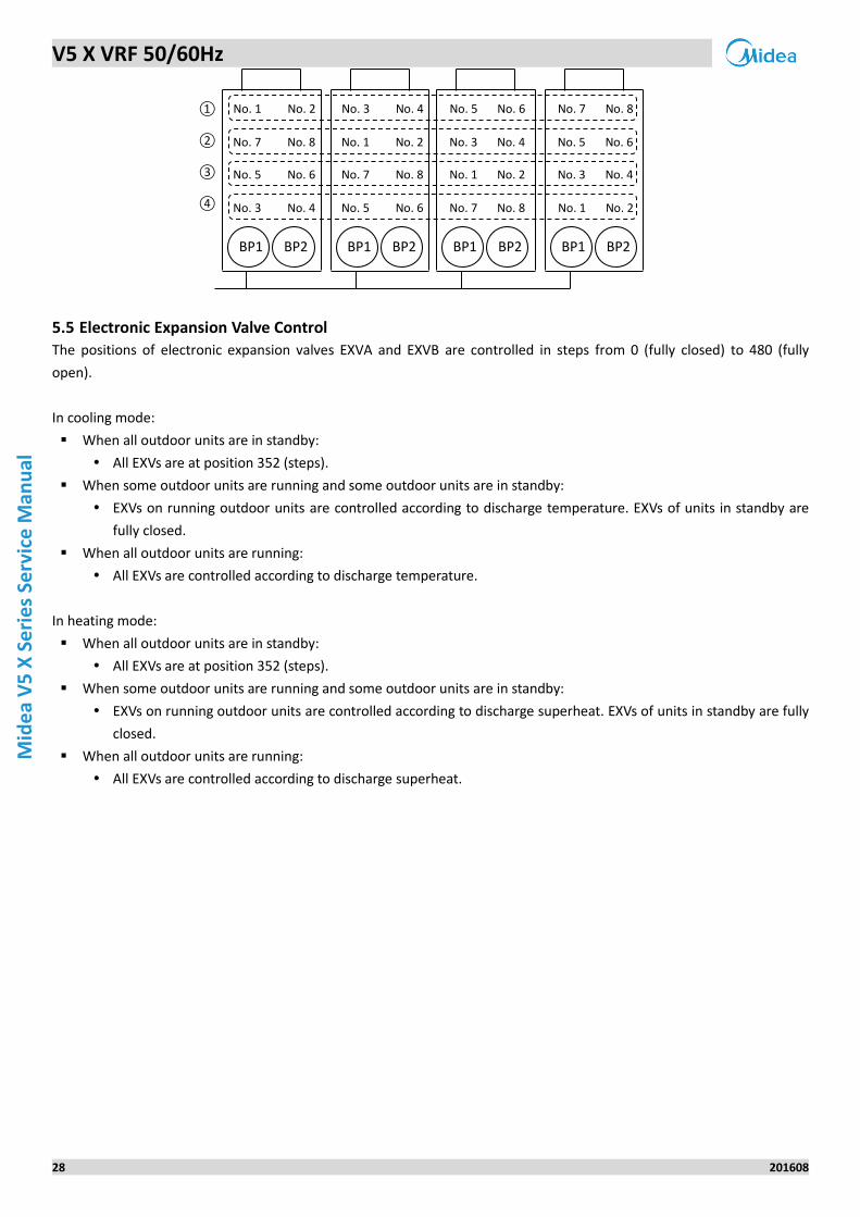
5.5 Electronic Expansion Valve Control
The positions of electronic expansion valves EXVA and EXVB are controlled in steps from 0 (fully closed) to 480 (fully
open).
In cooling mode:
When all outdoor units are in standby:
All EXVs are at position 352 (steps).
When some outdoor units are running and some outdoor units are in standby:
EXVs on running outdoor units are controlled according to discharge temperature. EXVs of units in standby are
fully closed.
When all outdoor units are running:
All EXVs are controlled according to discharge temperature.
In heating mode:
When all outdoor units are in standby:
All EXVs are at position 352 (steps).
When some outdoor units are running and some outdoor units are in standby:
EXVs on running outdoor units are controlled according to discharge superheat. EXVs of units in standby are fully
closed.
When all outdoor units are running:
All EXVs are controlled according to discharge superheat.
BP2 BP1
No. 1 No. 2 No. 3 No. 4 No. 5 No. 6 No. 7 No. 8
No. 7 No. 8 No. 1 No. 2 No. 3 No. 4 No. 5 No. 6
No. 5 No. 6 No. 7 No. 8 No. 1 No. 2 No. 3 No. 4
No. 3 No. 4 No. 5 No. 6 No. 7 No. 8 No. 1 No. 2
BP2 BP1 BP2 BP1 BP2 BP1
①
②
③
④
V5 X VRF 50/60Hz
201608 29
Part 3
- Co
ntro
l
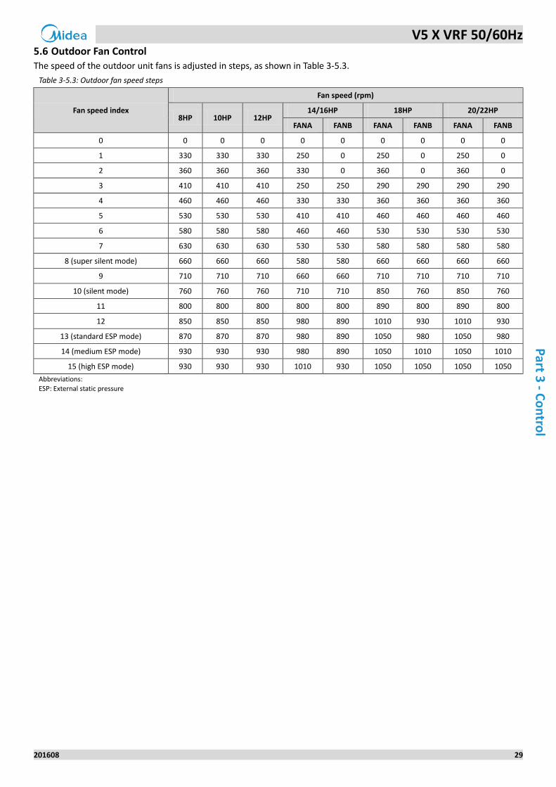
5.6 Outdoor Fan Control
The speed of the outdoor unit fans is adjusted in steps, as shown in Table 3-5.3.
Table 3-5.3: Outdoor fan speed steps
Fan speed index
Fan speed (rpm)
8HP 10HP 12HP 14/16HP 18HP 20/22HP
FANA FANB FANA FANB FANA FANB
0 0 0 0 0 0 0 0 0 0
1 330 330 330 250 0 250 0 250 0
2 360 360 360 330 0 360 0 360 0
3 410 410 410 250 250 290 290 290 290
4 460 460 460 330 330 360 360 360 360
5 530 530 530 410 410 460 460 460 460
6 580 580 580 460 460 530 530 530 530
7 630 630 630 530 530 580 580 580 580
8 (super silent mode) 660 660 660 580 580 660 660 660 660
9 710 710 710 660 660 710 710 710 710
10 (silent mode) 760 760 760 710 710 850 760 850 760
11 800 800 800 800 800 890 800 890 800
12 850 850 850 980 890 1010 930 1010 930
13 (standard ESP mode) 870 870 870 980 890 1050 980 1050 980
14 (medium ESP mode) 930 930 930 980 890 1050 1010 1050 1010
15 (high ESP mode) 930 930 930 1010 930 1050 1050 1050 1050
Abbreviations:
ESP: External static pressure
V5 X VRF 50/60Hz
30 201608
Mid
ea
V5
X S
eri
es
Serv
ice
Man
ual
6 Protection Control
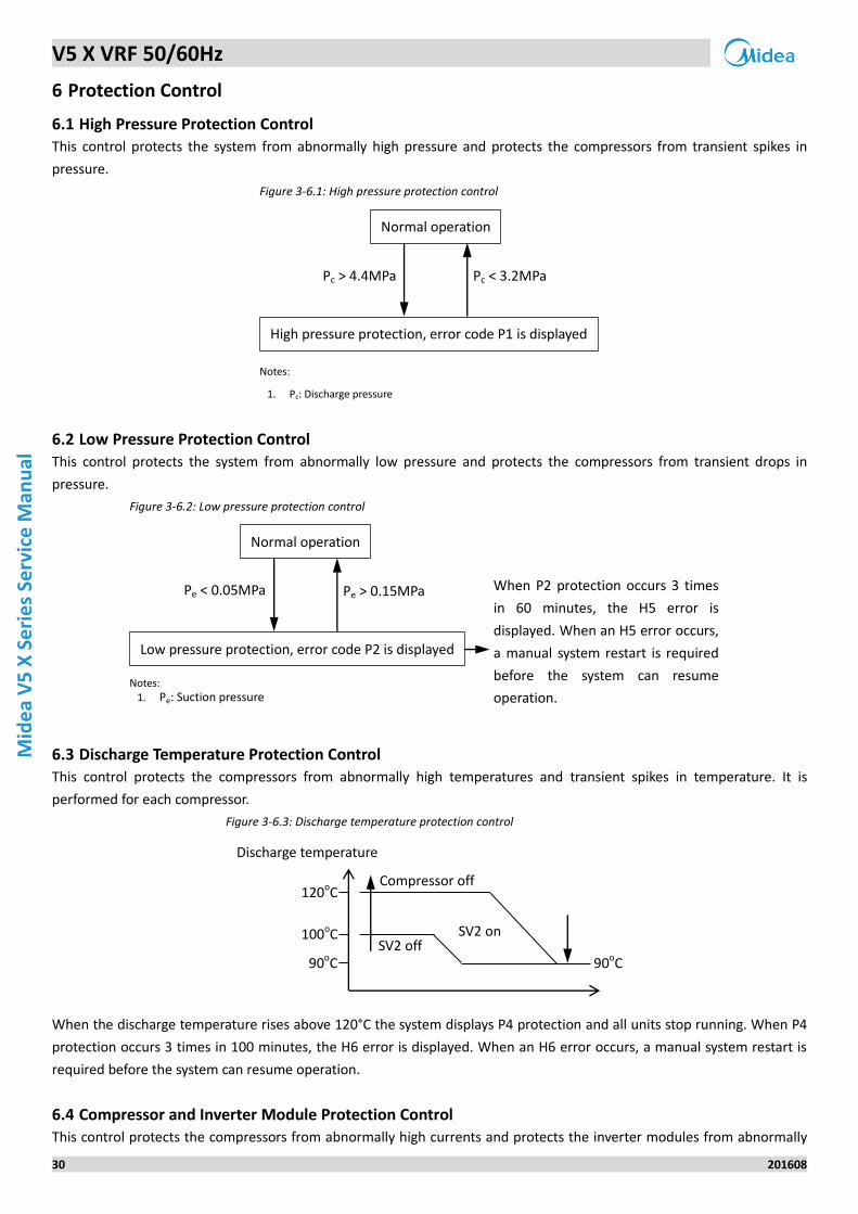
6.1 High Pressure Protection Control
This control protects the system from abnormally high pressure and protects the compressors from transient spikes in
pressure.
Figure 3-6.1: High pressure protection control
Notes:
1. Pc: Discharge pressure
6.2 Low Pressure Protection Control
This control protects the system from abnormally low pressure and protects the compressors from transient drops in
pressure.
Figure 3-6.2: Low pressure protection control
Notes: 1. Pe: Suction pressure
6.3 Discharge Temperature Protection Control
This control protects the compressors from abnormally high temperatures and transient spikes in temperature. It is
performed for each compressor.
Figure 3-6.3: Discharge temperature protection control
When the discharge temperature rises above 120°C the system displays P4 protection and all units stop running. When P4
protection occurs 3 times in 100 minutes, the H6 error is displayed. When an H6 error occurs, a manual system restart is
required before the system can resume operation.
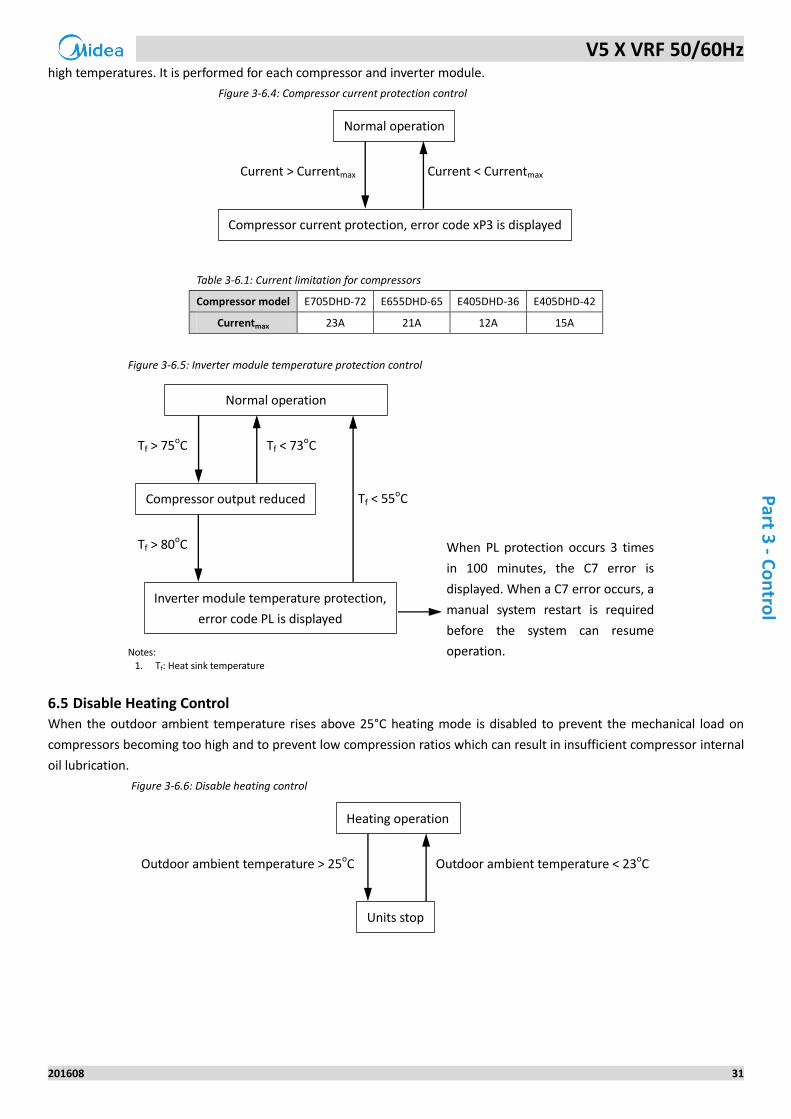
6.4 Compressor and Inverter Module Protection Control
This control protects the compressors from abnormally high currents and protects the inverter modules from abnormally
Pc > 4.4MPa Pc < 3.2MPa
Normal operation
High pressure protection, error code P1 is displayed
Pe < 0.05MPa Pe > 0.15MPa
Normal operation
Low pressure protection, error code P2 is displayed
When P2 protection occurs 3 times
in 60 minutes, the H5 error is
displayed. When an H5 error occurs,
a manual system restart is required
before the system can resume
operation.
120oC
100oC
90oC
Discharge temperature
Compressor off
SV2 off SV2 on
90oC
V5 X VRF 50/60Hz
201608 31
Part 3
- Co
ntro
l
high temperatures. It is performed for each compressor and inverter module.
Figure 3-6.4: Compressor current protection control
Table 3-6.1: Current limitation for compressors
Compressor model E705DHD-72 E655DHD-65 E405DHD-36 E405DHD-42
Currentmax 23A 21A 12A 15A
Figure 3-6.5: Inverter module temperature protection control
Notes:
1. Tf: Heat sink temperature
6.5 Disable Heating Control
When the outdoor ambient temperature rises above 25°C heating mode is disabled to prevent the mechanical load on
compressors becoming too high and to prevent low compression ratios which can result in insufficient compressor internal
oil lubrication.
Figure 3-6.6: Disable heating control
Current > Currentmax Current < Currentmax
Normal operation
Compressor current protection, error code xP3 is displayed
Tf > 75oC Tf < 73oC
Normal operation
Compressor output reduced
Tf > 80oC
Tf < 55oC
Inverter module temperature protection,
error code PL is displayed
When PL protection occurs 3 times
in 100 minutes, the C7 error is
displayed. When a C7 error occurs, a
manual system restart is required
before the system can resume
operation.
Outdoor ambient temperature > 25oC Outdoor ambient temperature < 23oC
Heating operation
Units stop
V5 X VRF 50/60Hz
32 201608
Mid
ea
V5
X S
eri
es
Serv
ice
Man
ual
7 Special Control
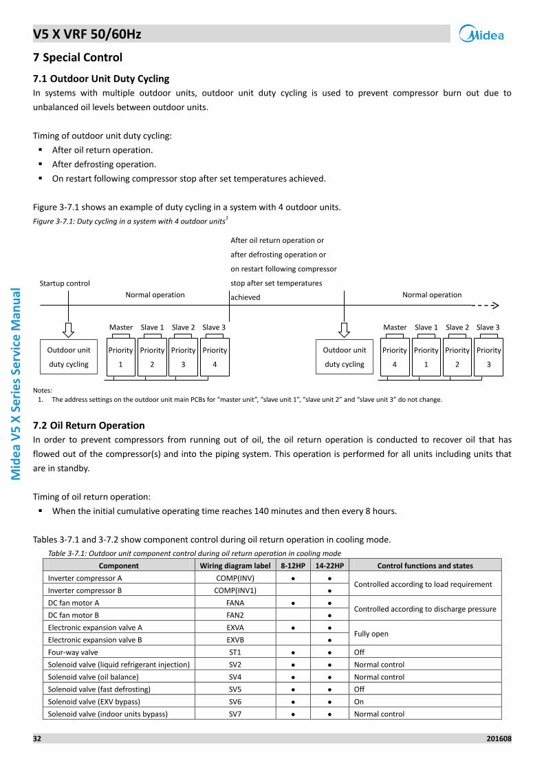
7.1 Outdoor Unit Duty Cycling
In systems with multiple outdoor units, outdoor unit duty cycling is used to prevent compressor burn out due to
unbalanced oil levels between outdoor units.
Timing of outdoor unit duty cycling:
After oil return operation.
After defrosting operation.
On restart following compressor stop after set temperatures achieved.
Figure 3-7.1 shows an example of duty cycling in a system with 4 outdoor units.
Figure 3-7.1: Duty cycling in a system with 4 outdoor units1
Notes:
1. The address settings on the outdoor unit main PCBs for “master unit”, “slave unit 1”, “slave unit 2” and “slave unit 3” do not change.
7.2 Oil Return Operation
In order to prevent compressors from running out of oil, the oil return operation is conducted to recover oil that has
flowed out of the compressor(s) and into the piping system. This operation is performed for all units including units that
are in standby.
Timing of oil return operation:
When the initial cumulative operating time reaches 140 minutes and then every 8 hours.
Tables 3-7.1 and 3-7.2 show component control during oil return operation in cooling mode.
Table 3-7.1: Outdoor unit component control during oil return operation in cooling mode
Component Wiring diagram label 8-12HP 14-22HP Control functions and states
Inverter compressor A COMP(INV) ● ● Controlled according to load requirement
Inverter compressor B COMP(INV1) ●
DC fan motor A FANA ● ● Controlled according to discharge pressure
DC fan motor B FAN2 ●
Electronic expansion valve A EXVA ● ● Fully open
Electronic expansion valve B EXVB ●
Four-way valve ST1 ● ● Off
Solenoid valve (liquid refrigerant injection) SV2 ● ● Normal control
Solenoid valve (oil balance) SV4 ● ● Normal control
Solenoid valve (fast defrosting) SV5 ● ● Off
Solenoid valve (EXV bypass) SV6 ● ● On
Solenoid valve (indoor units bypass) SV7 ● ● Normal control
Startup control
Normal operation
After oil return operation or
after defrosting operation or
on restart following compressor
stop after set temperatures
achieved Normal operation
Outdoor unit
duty cycling
Priority
1
Priority
2
Priority
3
Priority
4
Master Slave 1 Slave 2 Slave 3
Outdoor unit
duty cycling
Priority
4
Priority
1
Priority
2
Priority
3
Master Slave 1 Slave 2 Slave 3
V5 X VRF 50/60Hz
201608 33
Part 3
- Co
ntro
l
Table 3-7.2: Indoor unit component control during oil return operation in cooling mode
Component Unit state Control functions and states
Fan
Thermo on Remote controller setting
Standby Off
Thermo off Remote controller setting
Electronic expansion valve
Thermo on Normal control
Standby 300 (steps)
Thermo off 300 (steps)
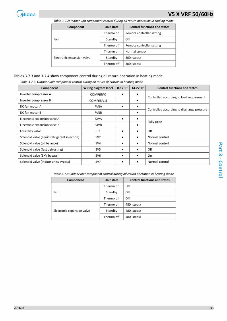
Tables 3-7.3 and 3-7.4 show component control during oil return operation in heating mode.
Table 3-7.3: Outdoor unit component control during oil return operation in heating mode
Component Wiring diagram label 8-12HP 14-22HP Control functions and states
Inverter compressor A COMP(INV) ● ● Controlled according to load requirement
Inverter compressor B COMP(INV1) ●
DC fan motor A FANA ● ● Controlled according to discharge pressure
DC fan motor B FANB ●
Electronic expansion valve A EXVA ● ● Fully open
Electronic expansion valve B EXVB ●
Four-way valve ST1 ● ● Off
Solenoid valve (liquid refrigerant injection) SV2 ● ● Normal control
Solenoid valve (oil balance) SV4 ● ● Normal control
Solenoid valve (fast defrosting) SV5 ● ● Off
Solenoid valve (EXV bypass) SV6 ● ● On
Solenoid valve (indoor units bypass) SV7 ● ● Normal control
Table 3-7.4: Indoor unit component control during oil return operation in heating mode
Component Unit state Control functions and states
Fan
Thermo on Off
Standby Off
Thermo off Off
Electronic expansion valve
Thermo on 480 (steps)
Standby 480 (steps)
Thermo off 480 (steps)
V5 X VRF 50/60Hz
34 201608
Mid
ea
V5
X S
eri
es
Serv
ice
Man
ual
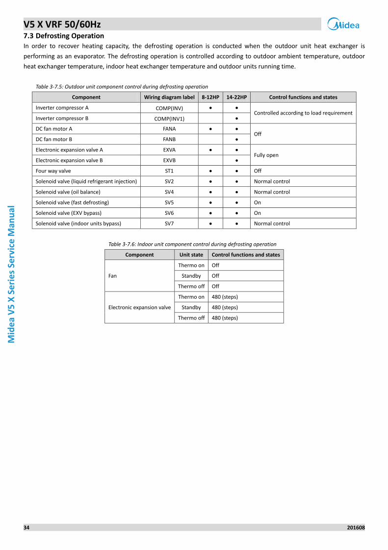
7.3 Defrosting Operation
In order to recover heating capacity, the defrosting operation is conducted when the outdoor unit heat exchanger is
performing as an evaporator. The defrosting operation is controlled according to outdoor ambient temperature, outdoor
heat exchanger temperature, indoor heat exchanger temperature and outdoor units running time.
Table 3-7.5: Outdoor unit component control during defrosting operation
Component Wiring diagram label 8-12HP 14-22HP Control functions and states
Inverter compressor A COMP(INV) ● ● Controlled according to load requirement
Inverter compressor B COMP(INV1) ●
DC fan motor A FANA ● ● Off
DC fan motor B FANB ●
Electronic expansion valve A EXVA ● ● Fully open
Electronic expansion valve B EXVB ●
Four way valve ST1 ● ● Off
Solenoid valve (liquid refrigerant injection) SV2 ● ● Normal control
Solenoid valve (oil balance) SV4 ● ● Normal control
Solenoid valve (fast defrosting) SV5 ● ● On
Solenoid valve (EXV bypass) SV6 ● ● On
Solenoid valve (indoor units bypass) SV7 ● ● Normal control
Table 3-7.6: Indoor unit component control during defrosting operation
Component Unit state Control functions and states
Fan
Thermo on Off
Standby Off
Thermo off Off
Electronic expansion valve
Thermo on 480 (steps)
Standby 480 (steps)
Thermo off 480 (steps)
V5 X VRF 50/60Hz
201608 35
Part 4
- Field
Settings
Part 4
Field Settings
1 Outdoor Unit Field Settings ................................................................. 36
V5 X VRF 50/60Hz
36 201608
Mid
ea
V5
X S
eri
es
Serv
ice
Man
ual
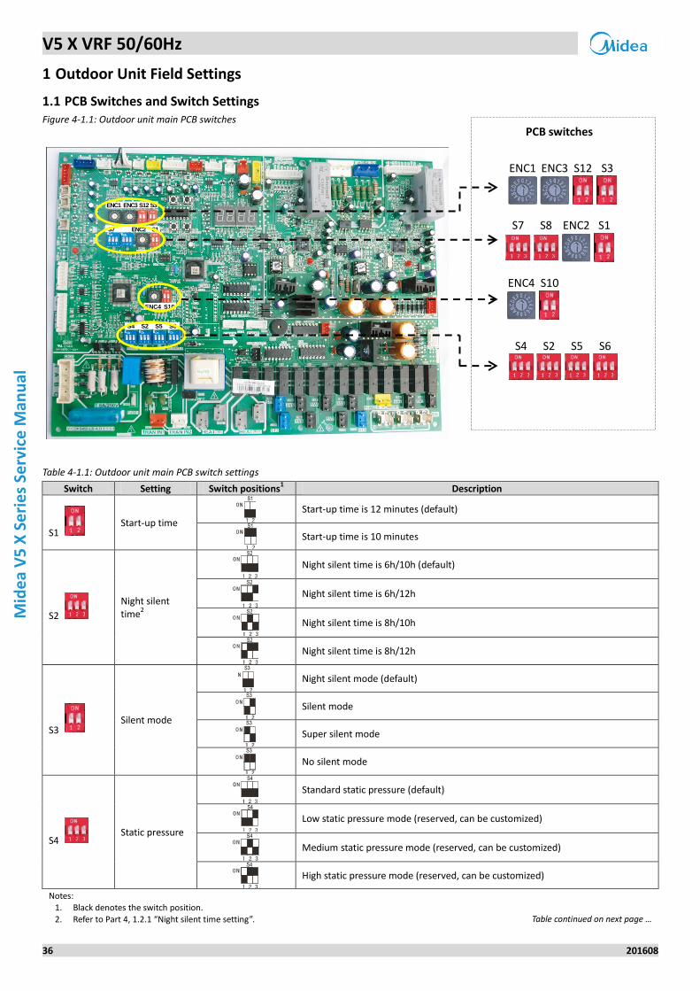
1 Outdoor Unit Field Settings
1.1 PCB Switches and Switch Settings Figure 4-1.1: Outdoor unit main PCB switches
Table 4-1.1: Outdoor unit main PCB switch settings
Switch Setting Switch positions1 Description
S1 Start-up time
Start-up time is 12 minutes (default)
Start-up time is 10 minutes
S2
Night silent time
2
Night silent time is 6h/10h (default)
Night silent time is 6h/12h
Night silent time is 8h/10h
Night silent time is 8h/12h
S3 Silent mode
Night silent mode (default)
Silent mode
Super silent mode
No silent mode
S4 Static pressure
Standard static pressure (default)
Low static pressure mode (reserved, can be customized)
Medium static pressure mode (reserved, can be customized)
High static pressure mode (reserved, can be customized)
Notes: 1. Black denotes the switch position. 2. Refer to Part 4, 1.2.1 “Night silent time setting”. Table continued on next page …
S1
S1
S2
S2
S2
S2
S3
S3
S3
S3
S4
S4
S4
S4
ENC1 ENC3 S12 S3
S7 S8 ENC2 S1
ENC4 S10
S4 S2 S5 S6
ENC1 ENC3 S12 S3
S7 S1ENC2
S4 S2 S5 S6
ENC4 S10
PCB switches
V5 X VRF 50/60Hz
201608 37
Part 4
- Field
Settings
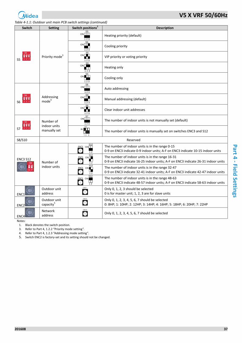
Table 4-1.1: Outdoor unit main PCB switch settings (continued)
Switch Setting Switch positions1 Description
S5 Priority mode
3
Heating priority (default)
Cooling priority
VIP priority or voting priority
Heating only
Cooling only
S6
Addressing mode
4
Auto addressing
Manual addressing (default)
Clear indoor unit addresses
S7
Number of indoor units manually set
The number of indoor units is not manually set (default)
1 2 3
S7ON
The number of indoor units is manually set on switches ENC3 and S12
S8/S10 Reserved
ENC3 S12
Number of indoor units
The number of indoor units is in the range 0-15 0-9 on ENC3 indicate 0-9 indoor units; A-F on ENC3 indicate 10-15 indoor units
The number of indoor units is in the range 16-31 0-9 on ENC3 indicate 16-25 indoor units; A-F on ENC3 indicate 26-31 indoor units
The number of indoor units is in the range 32-47 0-9 on ENC3 indicate 32-41 indoor units; A-F on ENC3 indicate 42-47 indoor units
The number of indoor units is in the range 48-63 0-9 on ENC3 indicate 48-57 indoor units; A-F on ENC3 indicate 58-63 indoor units
ENC1
Outdoor unit address
Only 0, 1, 2, 3 should be selected 0 is for master unit; 1, 2, 3 are for slave units
ENC2
Outdoor unit capacity
5
Only 0, 1, 2, 3, 4, 5, 6, 7 should be selected 0: 8HP; 1: 10HP; 2: 12HP; 3: 14HP; 4: 16HP; 5: 18HP; 6: 20HP; 7: 22HP
ENC4
Network address
Only 0, 1, 2, 3, 4, 5, 6, 7 should be selected
Notes: 1. Black denotes the switch position. 3. Refer to Part 4, 1.2.2 “Priority mode setting”.
4. Refer to Part 4, 1.2.3 “Addressing mode setting”. 5. Switch ENC2 is factory-set and its setting should not be changed.
1 2 3
S5ON
1 2 3
S5ON
1 2 3
S5ON
1 2 3
S5ON
1 2 3
S5ON
1 2 3
S6ON
1 2 3
S6ON
1 2 3
S6ON
1 2 3
S7ON
ENC3S12
ON
1 2
ENC3S12
ON
1 2
ENC3S12
ON
1 2
ENC3S12
ON
1 2
V5 X VRF 50/60Hz
38 201608
Mid
ea
V5
X S
eri
es
Serv
ice
Man
ual
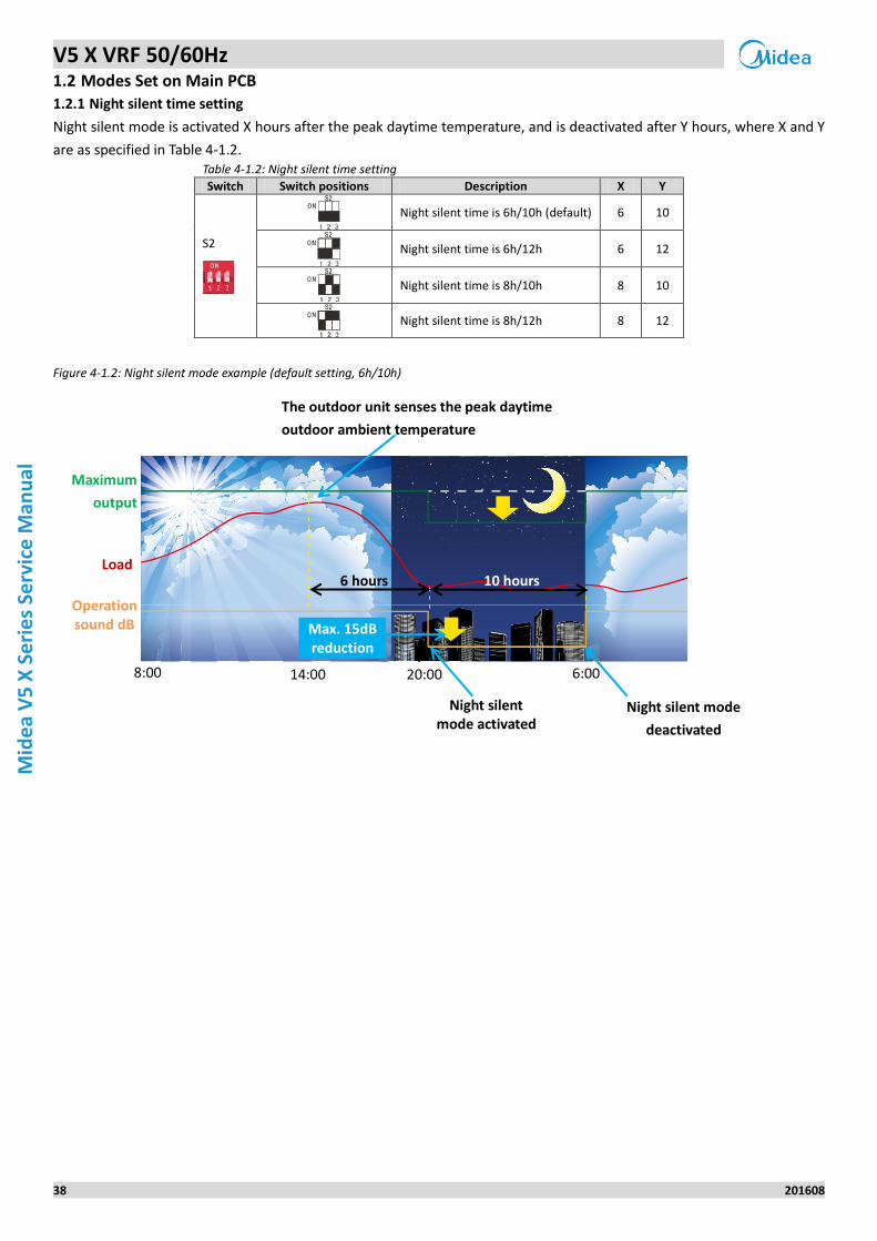
1.2 Modes Set on Main PCB
1.2.1 Night silent time setting
Night silent mode is activated X hours after the peak daytime temperature, and is deactivated after Y hours, where X and Y
are as specified in Table 4-1.2. Table 4-1.2: Night silent time setting
Switch Switch positions Description X Y
S2
Night silent time is 6h/10h (default) 6 10
Night silent time is 6h/12h 6 12
Night silent time is 8h/10h 8 10
Night silent time is 8h/12h 8 12
Figure 4-1.2: Night silent mode example (default setting, 6h/10h)
S2
S2
S2
S2
Operation sound dB
Load
Maximum
output
8:00 14:00 20:00 6:00
Night silent mode activated
The outdoor unit senses the peak daytime
outdoor ambient temperature
6 hours 10 hours
Night silent mode
deactivated
Max. 15dB reduction
V5 X VRF 50/60Hz
201608 39
Part 4
- Field
Settings
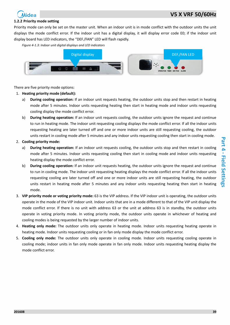
1.2.2 Priority mode setting
Priority mode can only be set on the master unit. When an indoor unit is in mode conflict with the outdoor units the unit
displays the mode conflict error. If the indoor unit has a digital display, it will display error code E0; if the indoor unit
display board has LED indicators, the “DEF./FAN” LED will flash rapidly.
Figure 4-1.3: Indoor unit digital displays and LED indicators
There are five priority mode options:
1. Heating priority mode (default):
a) During cooling operation: If an indoor unit requests heating, the outdoor units stop and then restart in heating
mode after 5 minutes. Indoor units requesting heating then start in heating mode and indoor units requesting
cooling display the mode conflict error.
b) During heating operation: If an indoor unit requests cooling, the outdoor units ignore the request and continue
to run in heating mode. The indoor unit requesting cooling displays the mode conflict error. If all the indoor units
requesting heating are later turned off and one or more indoor units are still requesting cooling, the outdoor
units restart in cooling mode after 5 minutes and any indoor units requesting cooling then start in cooling mode.
2. Cooling priority mode:
a) During heating operation: If an indoor unit requests cooling, the outdoor units stop and then restart in cooling
mode after 5 minutes. Indoor units requesting cooling then start in cooling mode and indoor units requesting
heating display the mode conflict error.
b) During cooling operation: If an indoor unit requests heating, the outdoor units ignore the request and continue
to run in cooling mode. The indoor unit requesting heating displays the mode conflict error. If all the indoor units
requesting cooling are later turned off and one or more indoor units are still requesting heating, the outdoor
units restart in heating mode after 5 minutes and any indoor units requesting heating then start in heating
mode.
3. VIP priority mode or voting priority mode: 63 is the VIP address. If the VIP indoor unit is operating, the outdoor units
operate in the mode of the VIP indoor unit. Indoor units that are in a mode different to that of the VIP unit display the
mode conflict error. If there is no unit with address 63 or the unit at address 63 is in standby, the outdoor units
operate in voting priority mode. In voting priority mode, the outdoor units operate in whichever of heating and
cooling modes is being requested by the larger number of indoor units.
4. Heating only mode: The outdoor units only operate in heating mode. Indoor units requesting heating operate in
heating mode. Indoor units requesting cooling or in fan only mode display the mode conflict error.
5. Cooling only mode: The outdoor units only operate in cooling mode. Indoor units requesting cooling operate in
cooling mode; indoor units in fan only mode operate in fan only mode. Indoor units requesting heating display the
mode conflict error.
DEF./FAN LED Digital display
V5 X VRF 50/60Hz
40 201608
Mid
ea
V5
X S
eri
es
Serv
ice
Man
ual
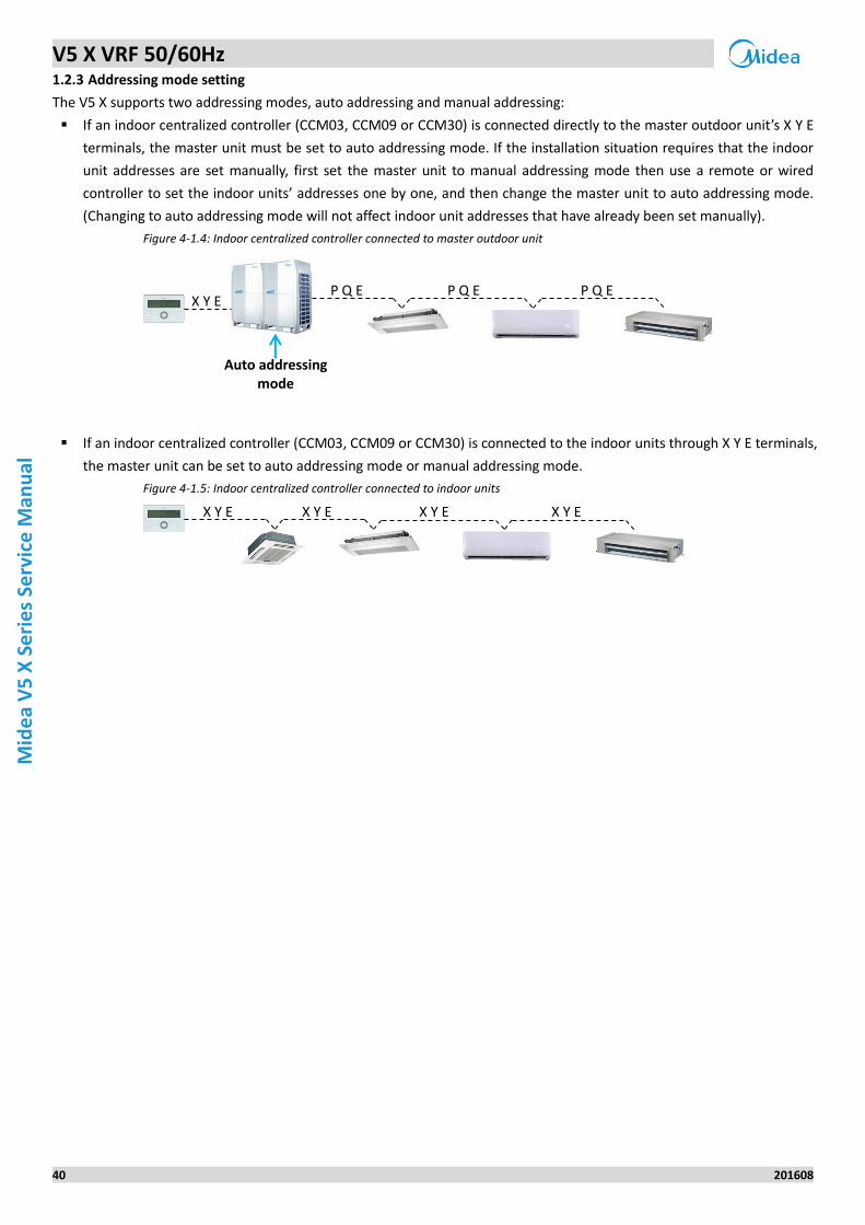
1.2.3 Addressing mode setting
The V5 X supports two addressing modes, auto addressing and manual addressing:
If an indoor centralized controller (CCM03, CCM09 or CCM30) is connected directly to the master outdoor unit’s X Y E
terminals, the master unit must be set to auto addressing mode. If the installation situation requires that the indoor
unit addresses are set manually, first set the master unit to manual addressing mode then use a remote or wired
controller to set the indoor units’ addresses one by one, and then change the master unit to auto addressing mode.
(Changing to auto addressing mode will not affect indoor unit addresses that have already been set manually).
Figure 4-1.4: Indoor centralized controller connected to master outdoor unit
If an indoor centralized controller (CCM03, CCM09 or CCM30) is connected to the indoor units through X Y E terminals,
the master unit can be set to auto addressing mode or manual addressing mode.
Figure 4-1.5: Indoor centralized controller connected to indoor units
Auto addressing mode
X Y E P Q E P Q E P Q E
X Y E X Y E X Y E X Y E
V5 X VRF 50/60Hz
201608 41
Part 5
- Diagn
osis an
d Tro
ub
lesh
oo
ting
Part 5
Diagnosis and
Troubleshooting
1 Outdoor Unit Electric Control Box Layout ............................................. 42
2 Outdoor Unit Main PCB ....................................................................... 43
3 Error Code Table .................................................................................. 47
4 Troubleshooting .................................................................................. 49
5 Appendix to Part 5 ............................................................................... 98
V5 X VRF 50/60Hz
42 201608
Mid
ea
V5
X S
eri
es
Serv
ice
Man
ual
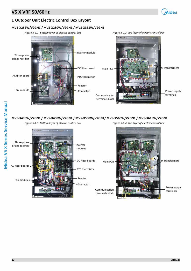
1 Outdoor Unit Electric Control Box Layout
MV5-X252W/V2GN1 / MV5-X280W/V2GN1 / MV5-X335W/V2GN1
Figure 5-1.1: Bottom layer of electric control box Figure 5-1.2: Top layer of electric control box
MV5-X400W/V2GN1 / MV5-X450W/V2GN1 / MV5-X500W/V2GN1/ MV5-X560W/V2GN1 / MV5-X615W/V2GN1
Figure 5-1.3: Bottom layer of electric control box Figure 5-1.4: Top layer of electric control box
Transformers
Power supply terminals Communication
terminals block
Main PCB
Reactor
Three-phase bridge rectifier
Inverter module
DC filter board
Fan module
PTC thermistor
Contactor
AC filter board
Inverter modules
DC filter boards
PTC thermistor
Reactor
Contactor
Three-phase bridge rectifier
Fan modules
AC filter boards
Transformers
Power supply terminals Communication
terminals block
Main PCB
V5 X VRF 50/60Hz
201608 43
Part 5
- Diagn
osis an
d Tro
ub
lesh
oo
ting
2 Outdoor Unit Main PCB
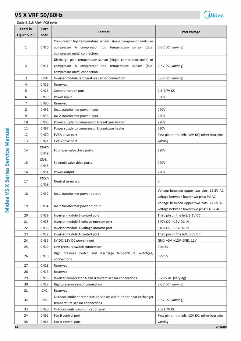
2.1 Types
There are four main PCB types for V5 X outdoor units. 8/10/12HP units share a main PCB type, 14/16HP share a main PCB
type, 18HP has a unique main PCB type, and 20/22HP share a main PCB type. The type label is affixed to the main PCB.
When changing a main PCB, be sure to use the right type of main PCB. Refer to Table 5-2.1.
Table 5-2.1: Main PCB type labels
Capacity 8/10/12HP 14/16HP 18HP 20/22HP1
Label
Notes:
1. The 20/22HP main PCB can also be used on 8/10/12HP units. The only difference is that the 20/22HP main PCB has two inverter modules whilst the 8/10/12HP main PCB has one inverter module. If a 20/22HP main PCB is used on an 8/10/12HP unit, the unit will run normally but LED6 will flash and LED7 will be continuously on.
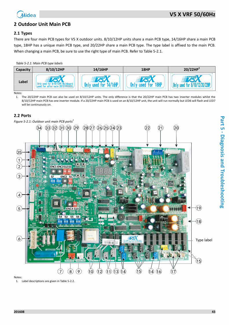
2.2 Ports Figure 5-2.1: Outdoor unit main PCB ports
1
Notes:
1. Label descriptions are given in Table 5-2.2.
Instruction
label
ENC1 ENC3S12S3
S7 S1ENC2
S4 S2 S5 S6
ENC4 S10
Type label
V5 X VRF 50/60Hz
44 201608
Mid
ea
V5
X S
eri
es
Serv
ice
Man
ual
Table 5-2.2: Main PCB ports
Label in
Figure 5-2.1
Port
code Content Port voltage
1 CN10
Compressor top temperature sensor (single compressor units) or
compressor A compressor top temperature sensor (dual
compressor units) connection
0-5V DC (varying)
2 CN11
Discharge pipe temperature sensor (single compressor units) or
compressor B compressor top temperature sensor (dual
compressor units) connection
0-5V DC (varying)
3 CN4 Inverter module temperature sensor connection 0-5V DC (varying)
4 CN26 Reserved
5 CN25 Communication port 2.5-2.7V DC
6 CN30 Power input 380V
7 CN80 Reserved
8 CN31 No.1 transformer power input 220V
9 CN33 No.2 transformer power input 220V
10 CN66 Power supply to compressor A crankcase heater 220V
11 CN67 Power supply to compressor B crankcase heater 220V
12 CN70 EVXA drive port First pin on the left: 12V DC; other four pins:
varying 13 CN71 EVXB drive port
14 CN47-
CN49 Four-way valve drive ports 220V
15 CN41-
CN45 Solenoid valve drive ports 220V
16 CN54 Power output 220V
17 CN57-
CN59 Neutral terminals 0
18 CN32 No.1 transformer power output Voltage between upper two pins: 13.5V AC;
voltage between lower two pins: 9V AC
19 CN34 No.2 transformer power output Voltage between upper two pins: 14.5V AC;
voltage between lower two pins: 14.5V AC
20 CN39 Inverter module B control port Third pin on the left: 3.3V DC
21 CN38 Inverter module B voltage monitor port 540V DC, +15V DC, N
22 CN36 Inverter module A voltage monitor port 540V DC, +15V DC, N
23 CN37 Inverter module A control port Third pin on the left: 3.3V DC
24 CN35 5V DC, 12V DC power input GND, +5V, +12V, GND, 12V
25 CN19 Low pressure switch connection 0 or 5V
26 CN18 High pressure switch and discharge temperature switch(es)
connections 0 or 5V
27 CN28 Reserved
28 CN16 Reserved
29 CN15 Inverter compressor A and B current sensor connections 0-7.8V AC (varying)
30 CN17 High pressure sensor connection 0-5V DC (varying)
31 CN2 Reserved
32 CN1 Outdoor ambient temperature sensor and outdoor heat exchanger
temperature sensor connections 0-5V DC (varying)
33 CN20 Outdoor units communication port 2.5-2.7V DC
34 CN65 Fan B control port First pin on the left: 12V DC; other four pins:
varying 35 CN64 Fan A control port
V5 X VRF 50/60Hz
201608 45
Part 5
- Diagn
osis an
d Tro
ub
lesh
oo
ting
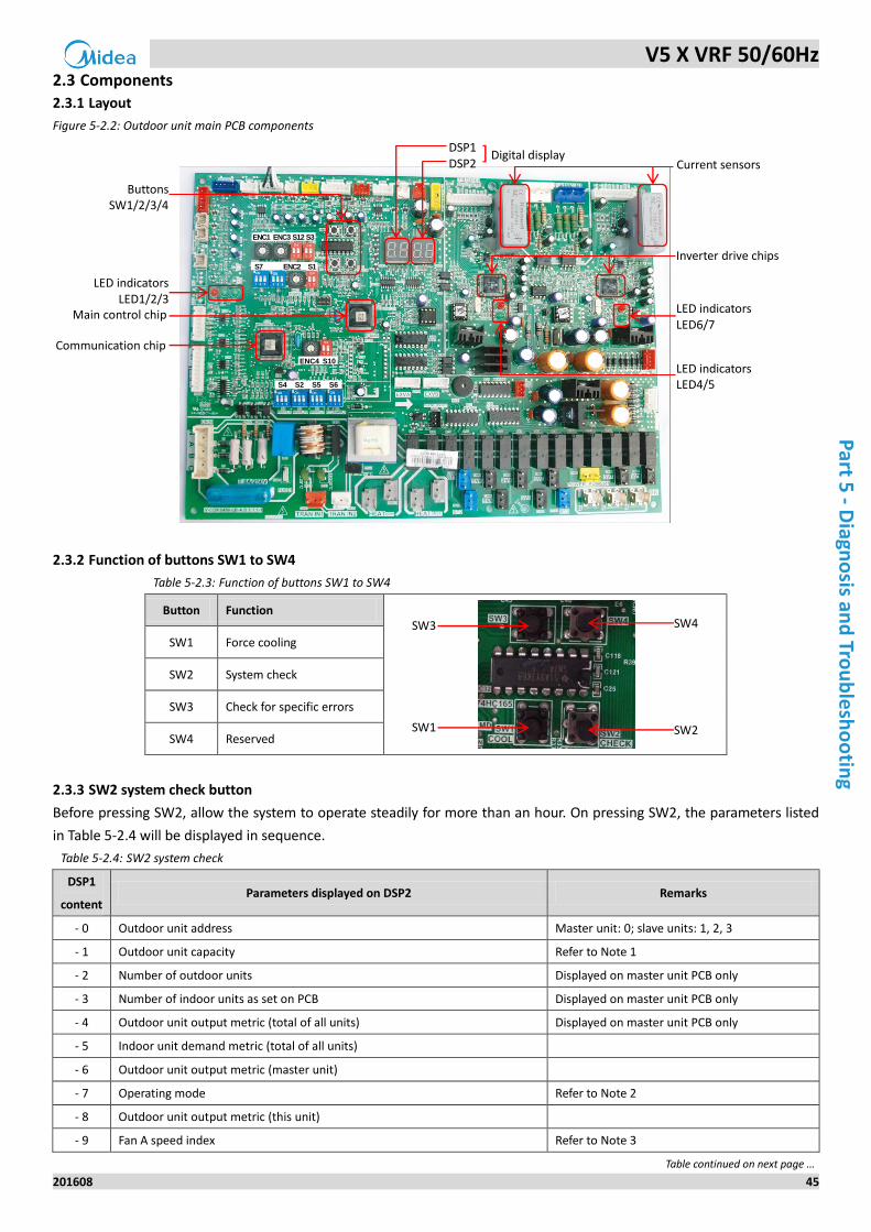
2.3 Components
Layout 2.3.1
Figure 5-2.2: Outdoor unit main PCB components
Function of buttons SW1 to SW4 2.3.2
Table 5-2.3: Function of buttons SW1 to SW4
Button Function
SW1 Force cooling
SW2 System check
SW3 Check for specific errors
SW4 Reserved
SW2 system check button 2.3.3
Before pressing SW2, allow the system to operate steadily for more than an hour. On pressing SW2, the parameters listed
in Table 5-2.4 will be displayed in sequence.
Table 5-2.4: SW2 system check
DSP1
content Parameters displayed on DSP2 Remarks
- 0 Outdoor unit address Master unit: 0; slave units: 1, 2, 3
- 1 Outdoor unit capacity Refer to Note 1
- 2 Number of outdoor units Displayed on master unit PCB only
- 3 Number of indoor units as set on PCB Displayed on master unit PCB only
- 4 Outdoor unit output metric (total of all units) Displayed on master unit PCB only
- 5 Indoor unit demand metric (total of all units)
- 6 Outdoor unit output metric (master unit)
- 7 Operating mode Refer to Note 2
- 8 Outdoor unit output metric (this unit)
- 9 Fan A speed index Refer to Note 3
Table continued on next page …
ENC1 ENC3 S12 S3
S7 S1ENC2
S4 S2 S5 S6
ENC4 S10
DSP1 DSP2
Buttons SW1/2/3/4
Main control chip
Communication chip
LED indicators LED1/2/3
Inverter drive chips
LED indicators LED6/7
LED indicators LED4/5
SW4
SW2
SW3
SW1
] Digital display Current sensors
V5 X VRF 50/60Hz
46 201608
Mid
ea
V5
X S
eri
es
Serv
ice
Man
ual
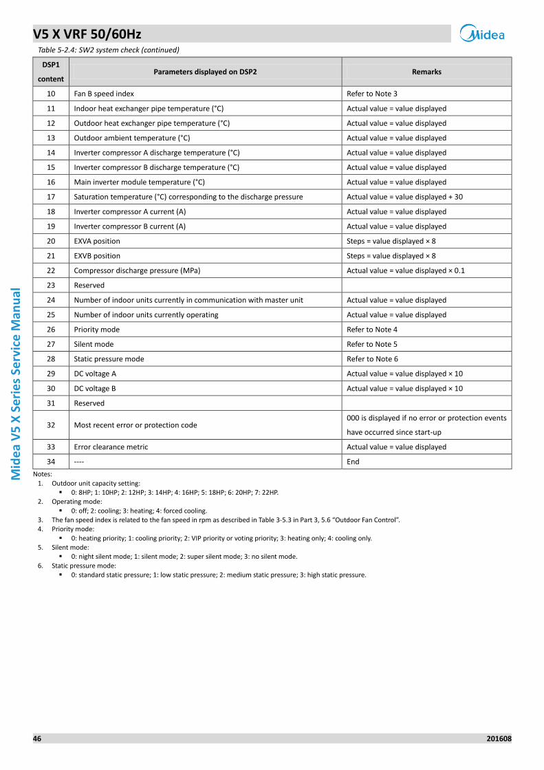
Table 5-2.4: SW2 system check (continued)
DSP1
content Parameters displayed on DSP2 Remarks
10 Fan B speed index Refer to Note 3
11 Indoor heat exchanger pipe temperature (°C) Actual value = value displayed
12 Outdoor heat exchanger pipe temperature (°C) Actual value = value displayed
13 Outdoor ambient temperature (°C) Actual value = value displayed
14 Inverter compressor A discharge temperature (°C) Actual value = value displayed
15 Inverter compressor B discharge temperature (°C) Actual value = value displayed
16 Main inverter module temperature (°C) Actual value = value displayed
17 Saturation temperature (°C) corresponding to the discharge pressure Actual value = value displayed + 30
18 Inverter compressor A current (A) Actual value = value displayed
19 Inverter compressor B current (A) Actual value = value displayed
20 EXVA position Steps = value displayed × 8
21 EXVB position Steps = value displayed × 8
22 Compressor discharge pressure (MPa) Actual value = value displayed × 0.1
23 Reserved
24 Number of indoor units currently in communication with master unit Actual value = value displayed
25 Number of indoor units currently operating Actual value = value displayed
26 Priority mode Refer to Note 4
27 Silent mode Refer to Note 5
28 Static pressure mode Refer to Note 6
29 DC voltage A Actual value = value displayed × 10
30 DC voltage B Actual value = value displayed × 10
31 Reserved
32 Most recent error or protection code 000 is displayed if no error or protection events
have occurred since start-up
33 Error clearance metric Actual value = value displayed
34 ---- End
Notes:
1. Outdoor unit capacity setting: 0: 8HP; 1: 10HP; 2: 12HP; 3: 14HP; 4: 16HP; 5: 18HP; 6: 20HP; 7: 22HP.
2. Operating mode:
0: off; 2: cooling; 3: heating; 4: forced cooling. 3. The fan speed index is related to the fan speed in rpm as described in Table 3-5.3 in Part 3, 5.6 “Outdoor Fan Control”. 4. Priority mode:
0: heating priority; 1: cooling priority; 2: VIP priority or voting priority; 3: heating only; 4: cooling only. 5. Silent mode:
0: night silent mode; 1: silent mode; 2: super silent mode; 3: no silent mode.
6. Static pressure mode: 0: standard static pressure; 1: low static pressure; 2: medium static pressure; 3: high static pressure.
V5 X VRF 50/60Hz
201608 47
Part 5
- Diagn
osis an
d Tro
ub
lesh
oo
ting
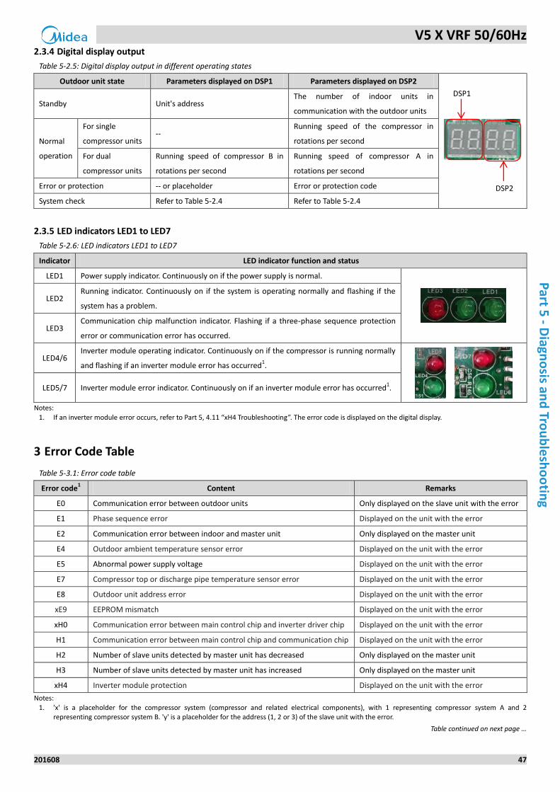
Digital display output 2.3.4
Table 5-2.5: Digital display output in different operating states
Outdoor unit state Parameters displayed on DSP1 Parameters displayed on DSP2
Standby Unit's address The number of indoor units in
communication with the outdoor units
Normal
operation
For single
compressor units --
Running speed of the compressor in
rotations per second
For dual
compressor units
Running speed of compressor B in
rotations per second
Running speed of compressor A in
rotations per second
Error or protection -- or placeholder Error or protection code
System check Refer to Table 5-2.4 Refer to Table 5-2.4
LED indicators LED1 to LED7 2.3.5
Table 5-2.6: LED indicators LED1 to LED7
Indicator LED indicator function and status
LED1 Power supply indicator. Continuously on if the power supply is normal.
LED2 Running indicator. Continuously on if the system is operating normally and flashing if the
system has a problem.
LED3 Communication chip malfunction indicator. Flashing if a three-phase sequence protection
error or communication error has occurred.
LED4/6 Inverter module operating indicator. Continuously on if the compressor is running normally
and flashing if an inverter module error has occurred1.
LED5/7 Inverter module error indicator. Continuously on if an inverter module error has occurred
1.
Notes:
1. If an inverter module error occurs, refer to Part 5, 4.11 “xH4 Troubleshooting”. The error code is displayed on the digital display.
3 Error Code Table
Table 5-3.1: Error code table
Error code1 Content Remarks
E0 Communication error between outdoor units Only displayed on the slave unit with the error
E1 Phase sequence error Displayed on the unit with the error
E2 Communication error between indoor and master unit Only displayed on the master unit
E4 Outdoor ambient temperature sensor error Displayed on the unit with the error
E5 Abnormal power supply voltage Displayed on the unit with the error
E7 Compressor top or discharge pipe temperature sensor error Displayed on the unit with the error
E8 Outdoor unit address error Displayed on the unit with the error
xE9 EEPROM mismatch Displayed on the unit with the error
xH0 Communication error between main control chip and inverter driver chip Displayed on the unit with the error
H1 Communication error between main control chip and communication chip Displayed on the unit with the error
H2 Number of slave units detected by master unit has decreased Only displayed on the master unit
H3 Number of slave units detected by master unit has increased Only displayed on the master unit
xH4 Inverter module protection Displayed on the unit with the error
Notes:
1. 'x' is a placeholder for the compressor system (compressor and related electrical components), with 1 representing compressor system A and 2 representing compressor system B. 'y' is a placeholder for the address (1, 2 or 3) of the slave unit with the error.
Table continued on next page …
DSP1
DSP2
V5 X VRF 50/60Hz
48 201608
Mid
ea
V5
X S
eri
es
Serv
ice
Man
ual
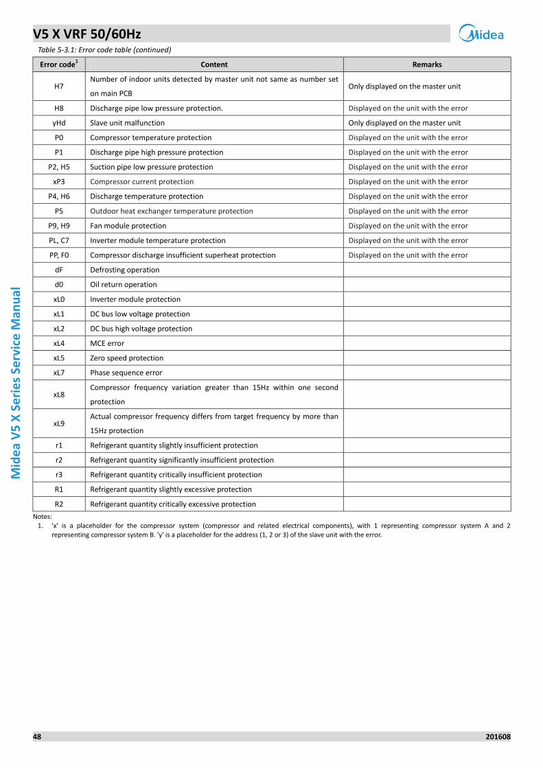
Table 5-3.1: Error code table (continued)
Error code1 Content Remarks
H7 Number of indoor units detected by master unit not same as number set
on main PCB Only displayed on the master unit
H8 Discharge pipe low pressure protection. Displayed on the unit with the error
yHd Slave unit malfunction Only displayed on the master unit
P0 Compressor temperature protection Displayed on the unit with the error
P1 Discharge pipe high pressure protection Displayed on the unit with the error
P2, H5 Suction pipe low pressure protection Displayed on the unit with the error
xP3 Compressor current protection Displayed on the unit with the error
P4, H6 Discharge temperature protection Displayed on the unit with the error
P5 Outdoor heat exchanger temperature protection Displayed on the unit with the error
P9, H9 Fan module protection Displayed on the unit with the error
PL, C7 Inverter module temperature protection Displayed on the unit with the error
PP, F0 Compressor discharge insufficient superheat protection Displayed on the unit with the error
dF Defrosting operation
d0 Oil return operation
xL0 Inverter module protection
xL1 DC bus low voltage protection
xL2 DC bus high voltage protection
xL4 MCE error
xL5 Zero speed protection
xL7 Phase sequence error
xL8 Compressor frequency variation greater than 15Hz within one second
protection
xL9 Actual compressor frequency differs from target frequency by more than
15Hz protection
r1 Refrigerant quantity slightly insufficient protection
r2 Refrigerant quantity significantly insufficient protection
r3 Refrigerant quantity critically insufficient protection
R1 Refrigerant quantity slightly excessive protection
R2 Refrigerant quantity critically excessive protection
Notes: 1. 'x' is a placeholder for the compressor system (compressor and related electrical components), with 1 representing compressor system A and 2
representing compressor system B. 'y' is a placeholder for the address (1, 2 or 3) of the slave unit with the error.
V5 X VRF 50/60Hz
201608 49
Part 5
- Diagn
osis an
d Tro
ub
lesh
oo
ting
4 Troubleshooting
4.1 Warning
All electrical work must be carried out by competent and suitably qualified, certified and
accredited professionals and in accordance with all applicable legislation (all national, local and other laws,
standards, codes, rules, regulations and other legislation that apply in a given situation).
Power-off the outdoor units before connecting or disconnecting any connections or wiring, otherwise electric
shock (which can cause physical injury or death) may occur or damage to components may occur.
Warning
V5 X VRF 50/60Hz
50 201608
Mid
ea
V5
X S
eri
es
Serv
ice
Man
ual
4.2 E0 Troubleshooting
Digital display output 4.2.1
Description 4.2.2
Communication error between outdoor units.
All units stop running.
Error code is only displayed on the slave unit with the error.
Possible causes 4.2.3
Incorrect outdoor unit address setting.
Communication wires between outdoor units not connected properly.
Loosened wiring within electric control box.
Damaged main PCB or electric control box communication terminals block.
V5 X VRF 50/60Hz
201608 51
Part 5
- Diagn
osis an
d Tro
ub
lesh
oo
ting
Procedure 4.2.4
E0
ODU addresses on switch ENC1 are set
incorrectly1 Yes Set the ODU addresses correctly
No
Communication wires between ODUs are
not connected properly2 Yes
Ensure the communication wires are
three-core shielded cable and are
connected properly
No
Wires between outdoor main PCB and
electric control box communication
terminals block are loose3
Yes Ensure the wires are connected properly
No
Replacing outdoor main PCB resolves the
error
No
Replace electric control box
communication terminals block4
Notes:
1. The master unit address should be set as 0, slave units addresses should be set from 1 to 3, and the addresses should not be repeated within one system. Refer to Part 4, 1.1 “PCB Switches and Switch Settings”.
2. All the wires for H1, H2, E connections should be three-core shielded cable, the wiring should be connected according to polarity (H1 to H1, etc), the wiring
should not be open or short circuited. Refer to the V5 X Engineering Data Book, Part 2, 5 “Wiring Diagrams” and Part 3, 9.3 “Communication Wiring”. 3. Refer to Figures 5-1.2 and 5-1.4 in Part 5, 1 “Outdoor Unit Electric Control Box Layout” and to the V5 X Engineering Data Book, Part 2, 5 “Wiring Diagrams”. 4. Refer to Figures 5-1.2 and 5-1.4 in Part 5, 1 “Outdoor Unit Electric Control Box Layout”.
V5 X VRF 50/60Hz
52 201608
Mid
ea
V5
X S
eri
es
Serv
ice
Man
ual
4.3 E1 Troubleshooting
Digital display output 4.3.1
Description 4.3.2
Phase sequence error.
All units stop running.
Error code is only displayed on the unit with the error.
Possible causes 4.3.3
Power supply phases not connected in correct sequence.
Power supply terminals loose.
Power supply abnormal.
Main PCB damaged.

V5 X VRF 50/60Hz
201608 53
Part 5
- Diagn
osis an
d Tro
ub
lesh
oo
ting
Procedure 4.3.4
E1
The phase sequence of the 3-phase
power supply is incrorrect1
Yes Exchange any two of the 3 phase wires
No
Some power supply terminals are loose2 Yes Ensure all supply terminals are securely
fastened
No
The power supply is abnormal Yes Check the power supply equipment
No
Replace outdoor main PCB
Notes:
1. The A, B, C terminals of 3-phase power supply should match compressor phase sequence requirements. If the phase sequence is inverted, the compressor will operate inversely. If the wiring connection of each outdoor unit is in A, B, C phase sequence, and multiple units are connected, the current difference between C phase and A, B phases will be very large as the power supply load of each outdoor unit will be on C phase. This can easily lead to tripped
circuits and terminal wiring burnout. Therefore if multiple units are to be used, the phase sequence should be staggered, so that the current is distributed among the three phases equally. Refer to Figures 5-1.2 and 5-1.4 in Part 5, 1 “Outdoor Unit Electric Control Box Layout”.
2. Loose power supply terminals can cause the compressors to operate abnormally and compressor current to be very large. Refer to Figures 5-1.2 and 5-1.4
in Part 5, 1 “Outdoor Unit Electric Control Box Layout”.
V5 X VRF 50/60Hz
54 201608
Mid
ea
V5
X S
eri
es
Serv
ice
Man
ual
4.4 E2 Troubleshooting
Digital display output 4.4.1
Description 4.4.2
Communication error between indoor and master unit.
All units stop running.
Error code is only displayed on the master unit.
Possible causes 4.4.3
Communication wires between indoor and outdoor units not connected properly.
Indoor unit power supply abnormal.
Loosened wiring within electric control box.
Interference from high voltage wires or other sources of electromagnetic radiation.
Communication wire too long.
Damaged main PCB or electric control box communication terminals block.
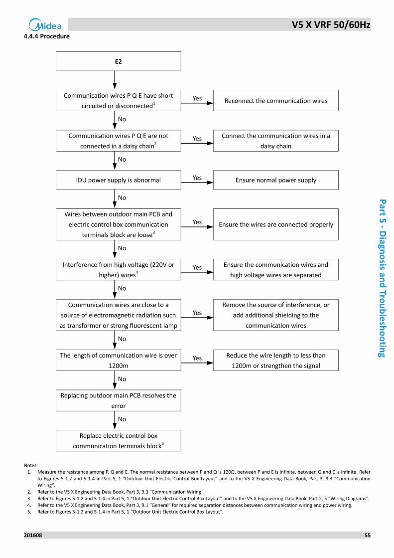
V5 X VRF 50/60Hz
201608 55
Part 5
- Diagn
osis an
d Tro
ub
lesh
oo
ting
Procedure 4.4.4
E2
Communication wires P Q E have short
circuited or disconnected1 Yes Reconnect the communication wires
No
Communication wires P Q E are not
connected in a daisy chain2 Yes Connect the communication wires in a
daisy chain
No
IDU power supply is abnormal Yes Ensure normal power supply
No
Wires between outdoor main PCB and
electric control box communication
terminals block are loose3
Yes Ensure the wires are connected properly
No
Interference from high voltage (220V or
higher) wires4 Yes Ensure the communication wires and
high voltage wires are separated
No
Communication wires are close to a
source of electromagnetic radiation such
as transformer or strong fluorescent lamp
Yes Remove the source of interference, or
add additional shielding to the
communication wires
No
The length of communication wire is over
1200m Yes Reduce the wire length to less than
1200m or strengthen the signal
No
Replacing outdoor main PCB resolves the
error
No
Replace electric control box
communication terminals block5
Notes:
1. Measure the resistance among P, Q and E. The normal resistance between P and Q is 120Ω, between P and E is infinite, between Q and E is infinite. Refer
to Figures 5-1.2 and 5-1.4 in Part 5, 1 “Outdoor Unit Electric Control Box Layout” and to the V5 X Engineering Data Book, Part 3, 9.3 “Communication Wiring”.
2. Refer to the V5 X Engineering Data Book, Part 3, 9.3 “Communication Wiring”.
3. Refer to Figures 5-1.2 and 5-1.4 in Part 5, 1 “Outdoor Unit Electric Control Box Layout” and to the V5 X Engineering Data Book, Part 2, 5 “Wiring Diagrams”. 4. Refer to the V5 X Engineering Data Book, Part 3, 9.1 “General” for required separation distances between communication wiring and power wiring. 5. Refer to Figures 5-1.2 and 5-1.4 in Part 5, 1 “Outdoor Unit Electric Control Box Layout”.
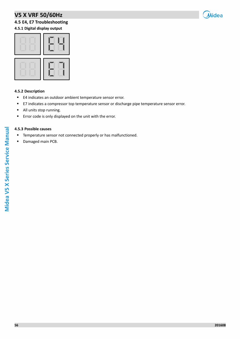
V5 X VRF 50/60Hz
56 201608
Mid
ea
V5
X S
eri
es
Serv
ice
Man
ual
4.5 E4, E7 Troubleshooting
Digital display output 4.5.1
Description 4.5.2
E4 indicates an outdoor ambient temperature sensor error.
E7 indicates a compressor top temperature sensor or discharge pipe temperature sensor error.
All units stop running.
Error code is only displayed on the unit with the error.
Possible causes 4.5.3
Temperature sensor not connected properly or has malfunctioned.
Damaged main PCB.
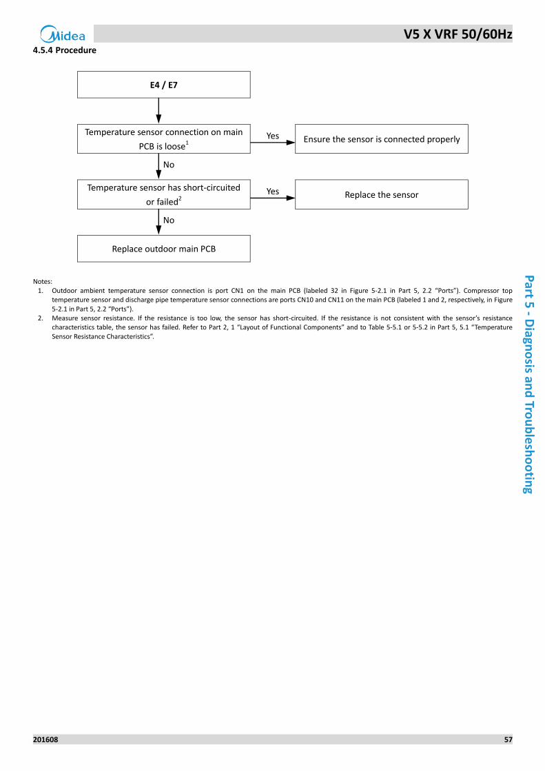
V5 X VRF 50/60Hz
201608 57
Part 5
- Diagn
osis an
d Tro
ub
lesh
oo
ting
Procedure 4.5.4
E4 / E7
Temperature sensor connection on main
PCB is loose1 Yes Ensure the sensor is connected properly
No
Temperature sensor has short-circuited
or failed2 Yes Replace the sensor
No
Replace outdoor main PCB
Notes:
1. Outdoor ambient temperature sensor connection is port CN1 on the main PCB (labeled 32 in Figure 5-2.1 in Part 5, 2.2 “Ports”). Compressor top temperature sensor and discharge pipe temperature sensor connections are ports CN10 and CN11 on the main PCB (labeled 1 and 2, respectively, in Figure
5-2.1 in Part 5, 2.2 “Ports”). 2. Measure sensor resistance. If the resistance is too low, the sensor has short-circuited. If the resistance is not consistent with the sensor’s resistance
characteristics table, the sensor has failed. Refer to Part 2, 1 “Layout of Functional Components” and to Table 5-5.1 or 5-5.2 in Part 5, 5.1 “Temperature
Sensor Resistance Characteristics”.
V5 X VRF 50/60Hz
58 201608
Mid
ea
V5
X S
eri
es
Serv
ice
Man
ual
4.6 E5 Troubleshooting
Digital display output 4.6.1
Description 4.6.2
Abnormal power supply voltage.
All units stop running.
Error code is only displayed on the unit with the error.
Possible causes 4.6.3
Outdoor unit power supply voltage not within ±10% of rated voltage or a phase is missing.
Loosened wiring within electric control box.
High voltage circuit error.
Main PCB damaged.
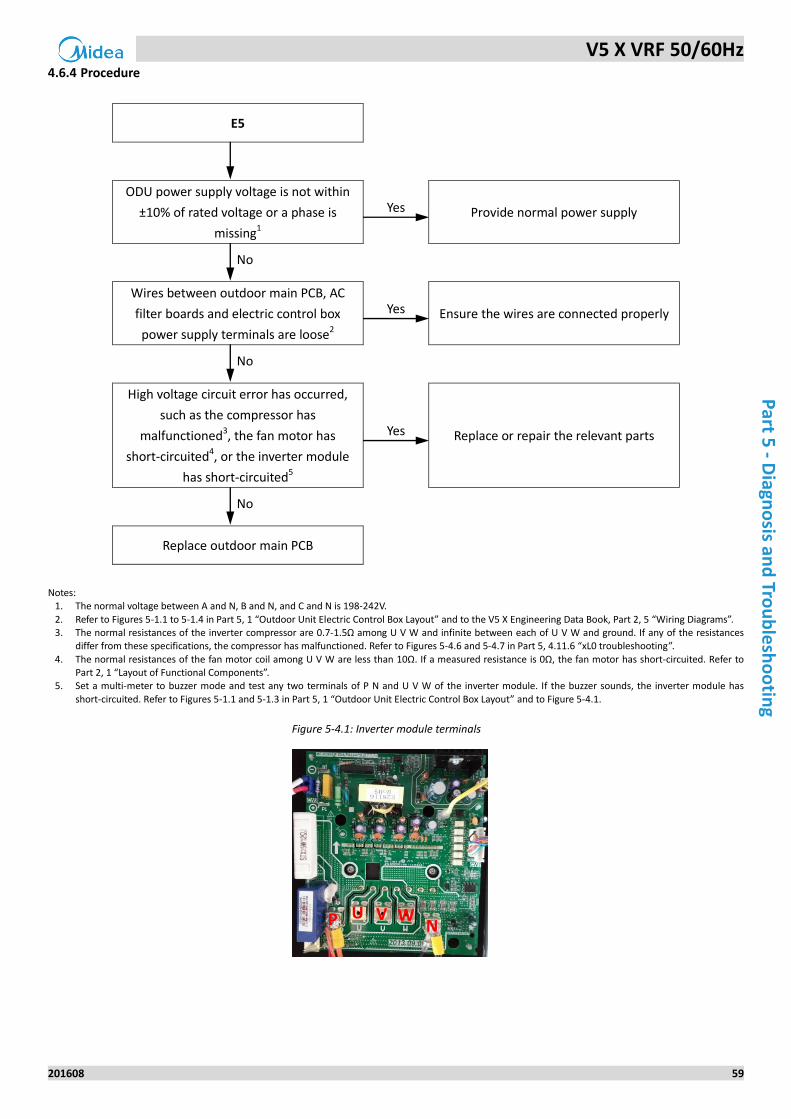
V5 X VRF 50/60Hz
201608 59
Part 5
- Diagn
osis an
d Tro
ub
lesh
oo
ting
Procedure 4.6.4
E5
ODU power supply voltage is not within
±10% of rated voltage or a phase is
missing1
Yes Provide normal power supply
No
Wires between outdoor main PCB, AC
filter boards and electric control box
power supply terminals are loose2
Yes Ensure the wires are connected properly
No
High voltage circuit error has occurred,
such as the compressor has
malfunctioned3, the fan motor has
short-circuited4, or the inverter module
has short-circuited5
Yes Replace or repair the relevant parts
No
Replace outdoor main PCB
Notes:
1. The normal voltage between A and N, B and N, and C and N is 198-242V.
2. Refer to Figures 5-1.1 to 5-1.4 in Part 5, 1 “Outdoor Unit Electric Control Box Layout” and to the V5 X Engineering Data Book, Part 2, 5 “Wiring Diagrams”. 3. The normal resistances of the inverter compressor are 0.7-1.5Ω among U V W and infinite between each of U V W and ground. If any of the resistances
differ from these specifications, the compressor has malfunctioned. Refer to Figures 5-4.6 and 5-4.7 in Part 5, 4.11.6 “xL0 troubleshooting”.
4. The normal resistances of the fan motor coil among U V W are less than 10Ω. If a measured resistance is 0Ω, the fan motor has short-circuited. Refer to Part 2, 1 “Layout of Functional Components”.
5. Set a multi-meter to buzzer mode and test any two terminals of P N and U V W of the inverter module. If the buzzer sounds, the inverter module has
short-circuited. Refer to Figures 5-1.1 and 5-1.3 in Part 5, 1 “Outdoor Unit Electric Control Box Layout” and to Figure 5-4.1.
Figure 5-4.1: Inverter module terminals
P N U V W
V5 X VRF 50/60Hz
60 201608
Mid
ea
V5
X S
eri
es
Serv
ice
Man
ual
4.7 E8 Troubleshooting
Digital display output 4.7.1
Description 4.7.2
Outdoor unit address error.
All units stop running.
Error code is only displayed on the unit with the error.
Possible causes 4.7.3
Invalid outdoor unit address.
Main PCB damaged.
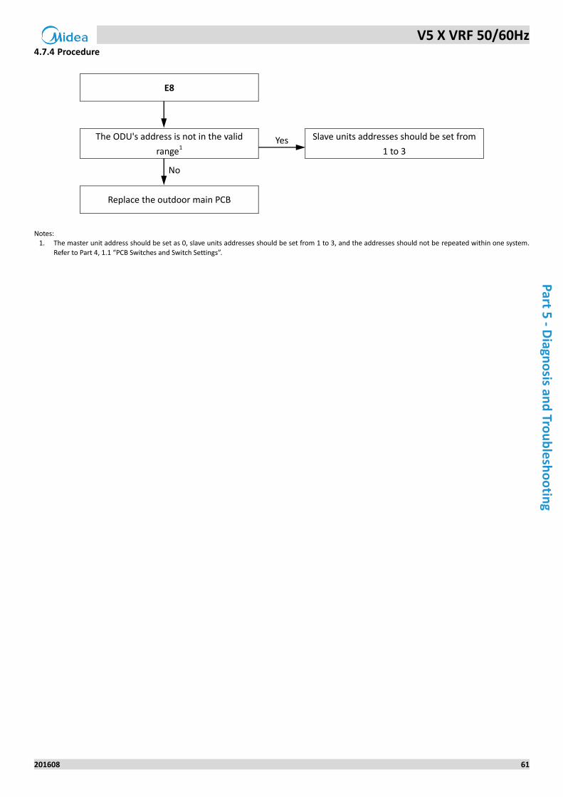
V5 X VRF 50/60Hz
201608 61
Part 5
- Diagn
osis an
d Tro
ub
lesh
oo
ting
Procedure 4.7.4
E8
The ODU's address is not in the valid
range1 Yes Slave units addresses should be set from
1 to 3
No
Replace the outdoor main PCB
Notes:
1. The master unit address should be set as 0, slave units addresses should be set from 1 to 3, and the addresses should not be repeated within one system.
Refer to Part 4, 1.1 “PCB Switches and Switch Settings”.
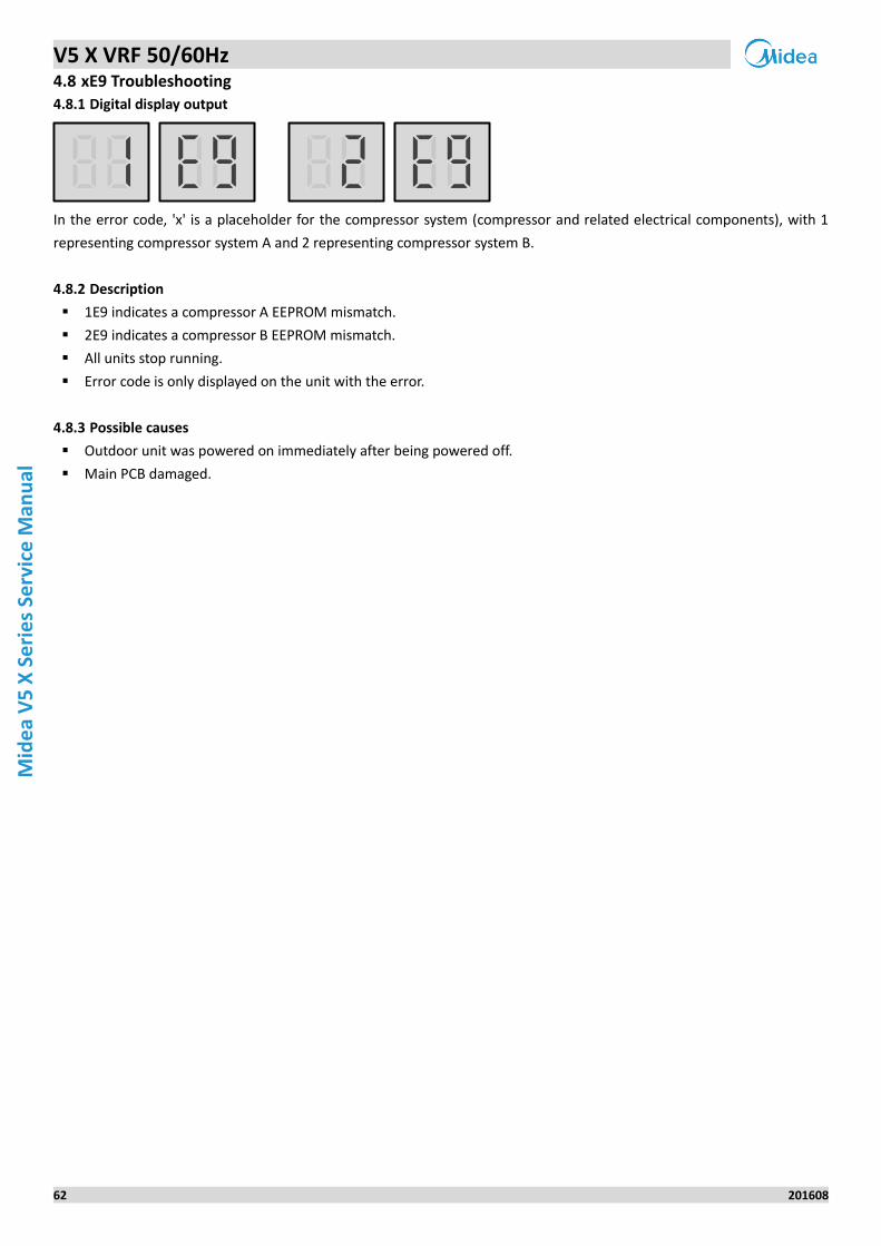
V5 X VRF 50/60Hz
62 201608
Mid
ea
V5
X S
eri
es
Serv
ice
Man
ual
4.8 xE9 Troubleshooting
Digital display output 4.8.1
In the error code, 'x' is a placeholder for the compressor system (compressor and related electrical components), with 1
representing compressor system A and 2 representing compressor system B.
Description 4.8.2
1E9 indicates a compressor A EEPROM mismatch.
2E9 indicates a compressor B EEPROM mismatch.
All units stop running.
Error code is only displayed on the unit with the error.
Possible causes 4.8.3
Outdoor unit was powered on immediately after being powered off.
Main PCB damaged.
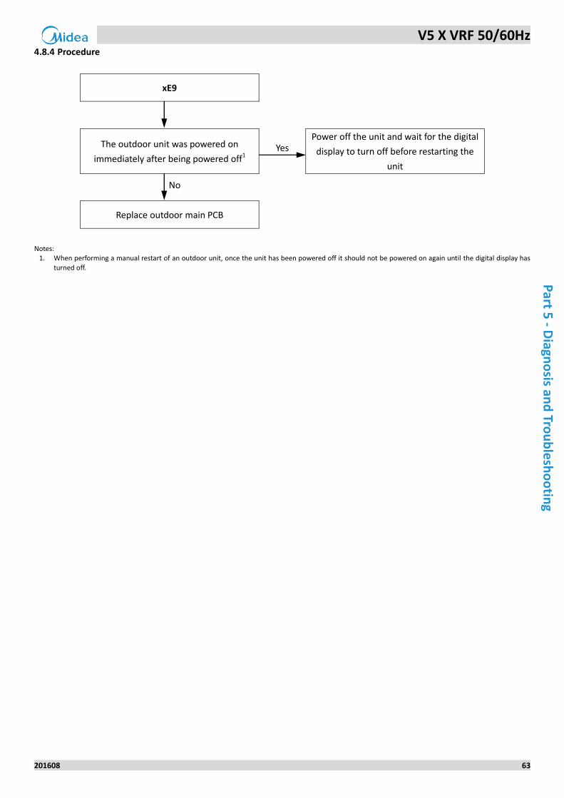
V5 X VRF 50/60Hz
201608 63
Part 5
- Diagn
osis an
d Tro
ub
lesh
oo
ting
Procedure 4.8.4
xE9
The outdoor unit was powered on
immediately after being powered off1 Yes
Power off the unit and wait for the digital
display to turn off before restarting the
unit
No
Replace outdoor main PCB
Notes:
1. When performing a manual restart of an outdoor unit, once the unit has been powered off it should not be powered on again until the digital display has
turned off.
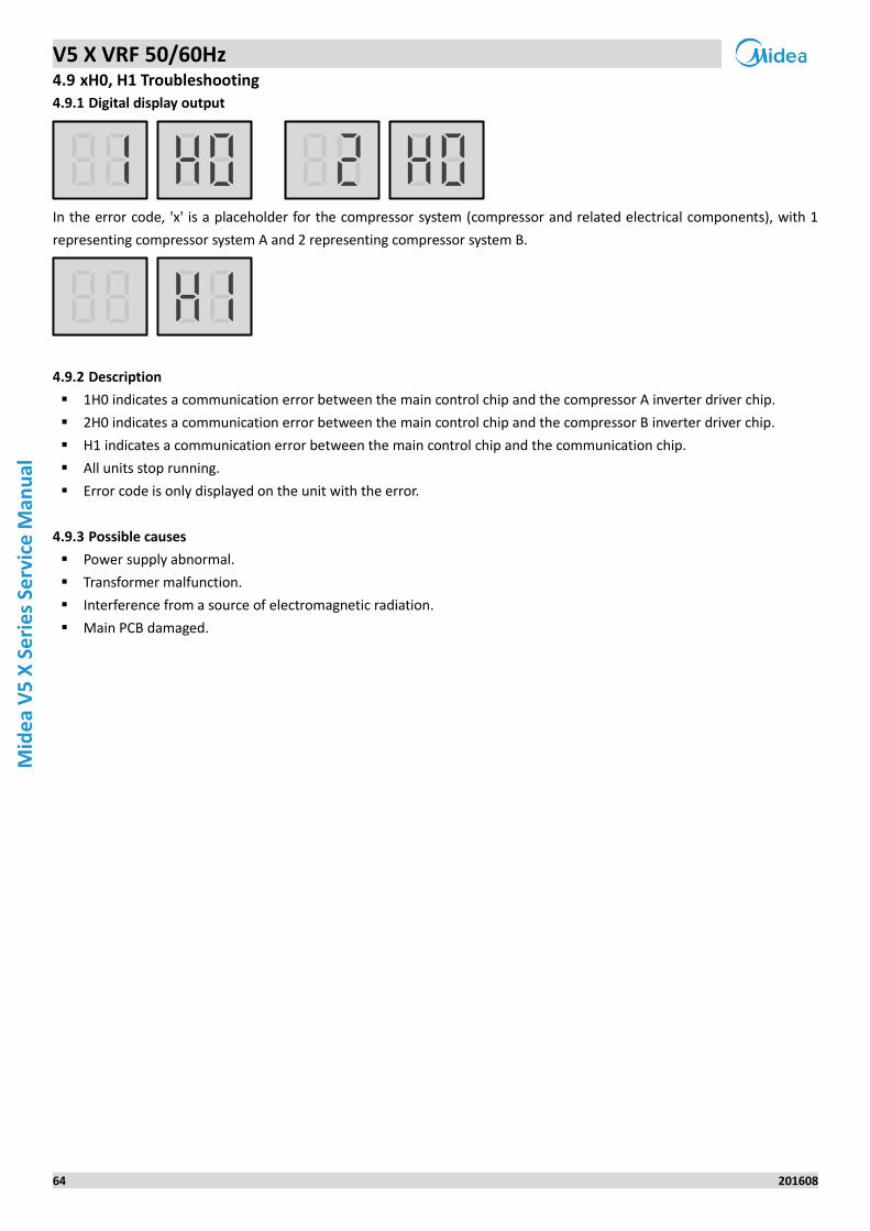
V5 X VRF 50/60Hz
64 201608
Mid
ea
V5
X S
eri
es
Serv
ice
Man
ual
4.9 xH0, H1 Troubleshooting
Digital display output 4.9.1
In the error code, 'x' is a placeholder for the compressor system (compressor and related electrical components), with 1
representing compressor system A and 2 representing compressor system B.
Description 4.9.2
1H0 indicates a communication error between the main control chip and the compressor A inverter driver chip.
2H0 indicates a communication error between the main control chip and the compressor B inverter driver chip.
H1 indicates a communication error between the main control chip and the communication chip.
All units stop running.
Error code is only displayed on the unit with the error.
Possible causes 4.9.3
Power supply abnormal.
Transformer malfunction.
Interference from a source of electromagnetic radiation.
Main PCB damaged.
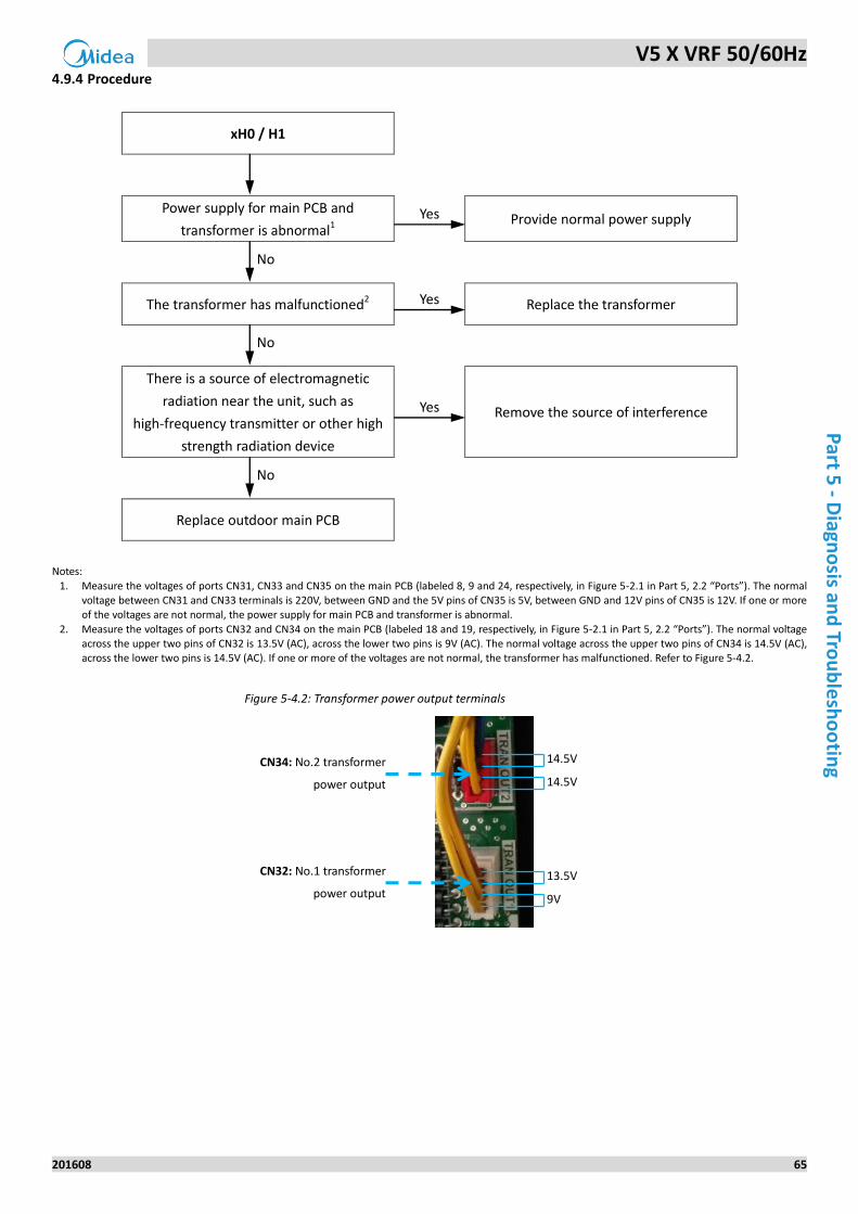
V5 X VRF 50/60Hz
201608 65
Part 5
- Diagn
osis an
d Tro
ub
lesh
oo
ting
Procedure 4.9.4
xH0 / H1
Power supply for main PCB and
transformer is abnormal1 Yes Provide normal power supply
No
The transformer has malfunctioned2 Yes Replace the transformer
No
There is a source of electromagnetic
radiation near the unit, such as
high-frequency transmitter or other high
strength radiation device
Yes Remove the source of interference
No
Replace outdoor main PCB
Notes:
1. Measure the voltages of ports CN31, CN33 and CN35 on the main PCB (labeled 8, 9 and 24, respectively, in Figure 5-2.1 in Part 5, 2.2 “Ports”). The normal voltage between CN31 and CN33 terminals is 220V, between GND and the 5V pins of CN35 is 5V, between GND and 12V pins of CN35 is 12V. If one or more of the voltages are not normal, the power supply for main PCB and transformer is abnormal.
2. Measure the voltages of ports CN32 and CN34 on the main PCB (labeled 18 and 19, respectively, in Figure 5-2.1 in Part 5, 2.2 “Ports”). The normal voltage across the upper two pins of CN32 is 13.5V (AC), across the lower two pins is 9V (AC). The normal voltage across the upper two pins of CN34 is 14.5V (AC), across the lower two pins is 14.5V (AC). If one or more of the voltages are not normal, the transformer has malfunctioned. Refer to Figure 5-4.2.
Figure 5-4.2: Transformer power output terminals
13.5V
9V
14.5V
14.5V
CN34: No.2 transformer
power output
CN32: No.1 transformer
power output
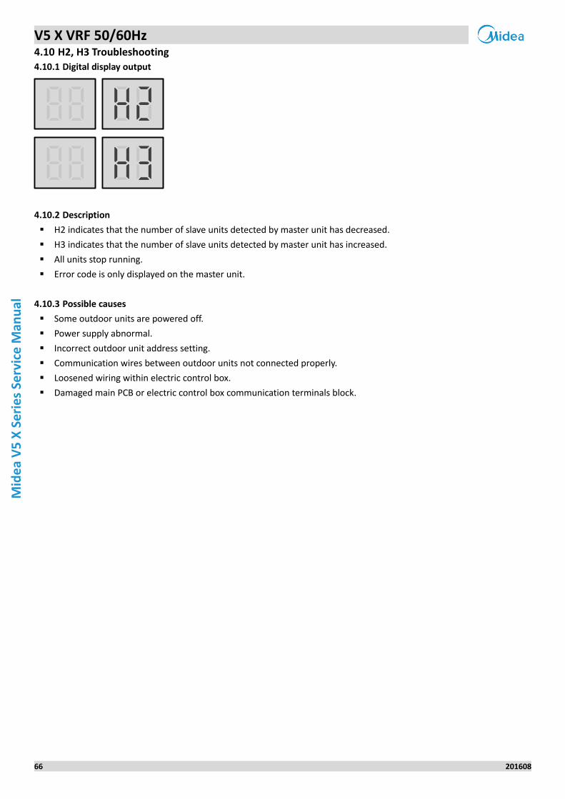
V5 X VRF 50/60Hz
66 201608
Mid
ea
V5
X S
eri
es
Serv
ice
Man
ual
4.10 H2, H3 Troubleshooting
Digital display output 4.10.1
Description 4.10.2
H2 indicates that the number of slave units detected by master unit has decreased.
H3 indicates that the number of slave units detected by master unit has increased.
All units stop running.
Error code is only displayed on the master unit.
Possible causes 4.10.3
Some outdoor units are powered off.
Power supply abnormal.
Incorrect outdoor unit address setting.
Communication wires between outdoor units not connected properly.
Loosened wiring within electric control box.
Damaged main PCB or electric control box communication terminals block.
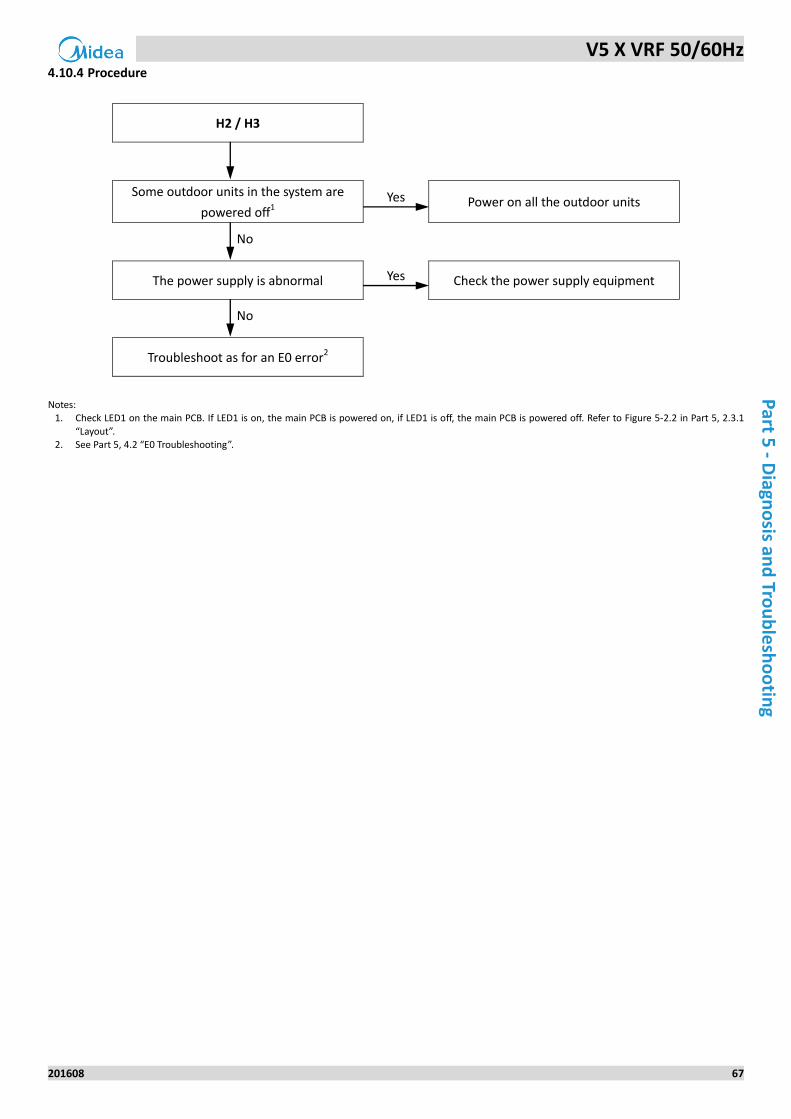
V5 X VRF 50/60Hz
201608 67
Part 5
- Diagn
osis an
d Tro
ub
lesh
oo
ting
Procedure 4.10.4
H2 / H3
Some outdoor units in the system are
powered off1 Yes Power on all the outdoor units
No
The power supply is abnormal Yes Check the power supply equipment
No
Troubleshoot as for an E0 error2
Notes:
1. Check LED1 on the main PCB. If LED1 is on, the main PCB is powered on, if LED1 is off, the main PCB is powered off. Refer to Figure 5-2.2 in Part 5, 2.3.1
“Layout”. 2. See Part 5, 4.2 “E0 Troubleshooting”.
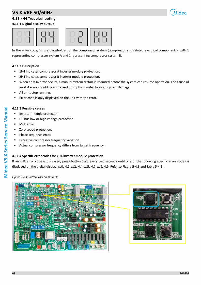
V5 X VRF 50/60Hz
68 201608
Mid
ea
V5
X S
eri
es
Serv
ice
Man
ual
4.11 xH4 Troubleshooting
Digital display output 4.11.1
In the error code, 'x' is a placeholder for the compressor system (compressor and related electrical components), with 1
representing compressor system A and 2 representing compressor system B.
Description 4.11.2
1H4 indicates compressor A inverter module protection.
2H4 indicates compressor B inverter module protection.
When an xH4 error occurs, a manual system restart is required before the system can resume operation. The cause of
an xH4 error should be addressed promptly in order to avoid system damage.
All units stop running.
Error code is only displayed on the unit with the error.
Possible causes 4.11.3
Inverter module protection.
DC bus low or high voltage protection.
MCE error.
Zero speed protection.
Phase sequence error.
Excessive compressor frequency variation.
Actual compressor frequency differs from target frequency.
Specific error codes for xH4 inverter module protection 4.11.4
If an xH4 error code is displayed, press button SW3 every two seconds until one of the following specific error codes is
displayed on the digital display: xL0, xL1, xL2, xL4, xL5, xL7, xL8, xL9. Refer to Figure 5-4.3 and Table 5-4.1.
Figure 5-4.3: Button SW3 on main PCB
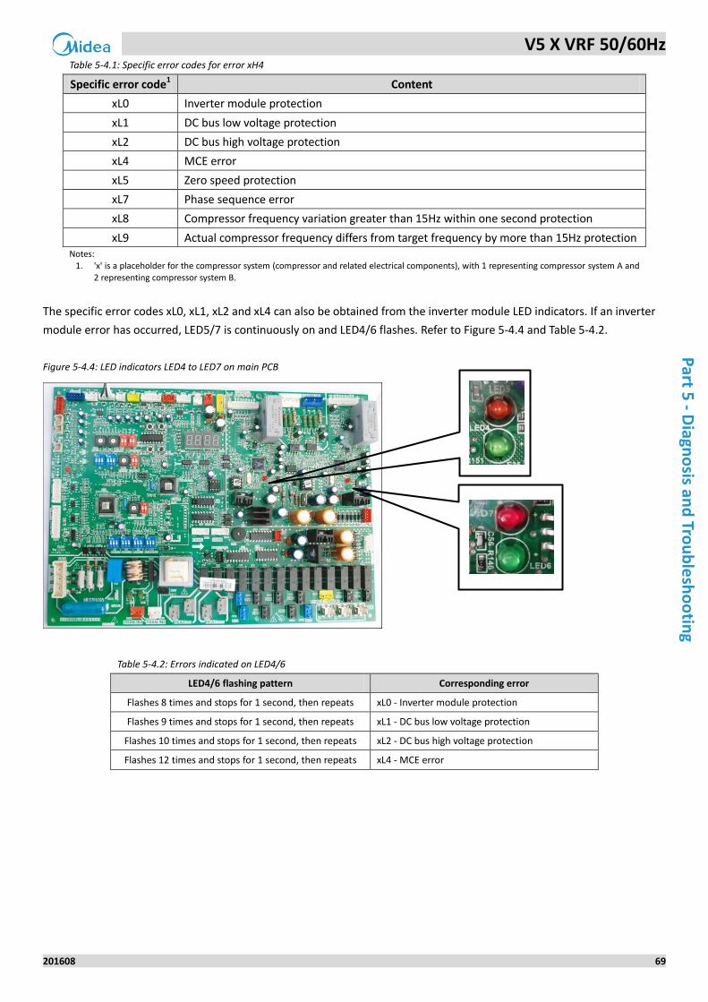
V5 X VRF 50/60Hz
201608 69
Part 5
- Diagn
osis an
d Tro
ub
lesh
oo
ting
Table 5-4.1: Specific error codes for error xH4
Specific error code1 Content
xL0 Inverter module protection
xL1 DC bus low voltage protection
xL2 DC bus high voltage protection
xL4 MCE error
xL5 Zero speed protection
xL7 Phase sequence error
xL8 Compressor frequency variation greater than 15Hz within one second protection
xL9 Actual compressor frequency differs from target frequency by more than 15Hz protection Notes:
1. 'x' is a placeholder for the compressor system (compressor and related electrical components), with 1 representing compressor system A and 2 representing compressor system B.
The specific error codes xL0, xL1, xL2 and xL4 can also be obtained from the inverter module LED indicators. If an inverter
module error has occurred, LED5/7 is continuously on and LED4/6 flashes. Refer to Figure 5-4.4 and Table 5-4.2.
Figure 5-4.4: LED indicators LED4 to LED7 on main PCB
Table 5-4.2: Errors indicated on LED4/6
LED4/6 flashing pattern Corresponding error
Flashes 8 times and stops for 1 second, then repeats xL0 - Inverter module protection
Flashes 9 times and stops for 1 second, then repeats xL1 - DC bus low voltage protection
Flashes 10 times and stops for 1 second, then repeats xL2 - DC bus high voltage protection
Flashes 12 times and stops for 1 second, then repeats xL4 - MCE error
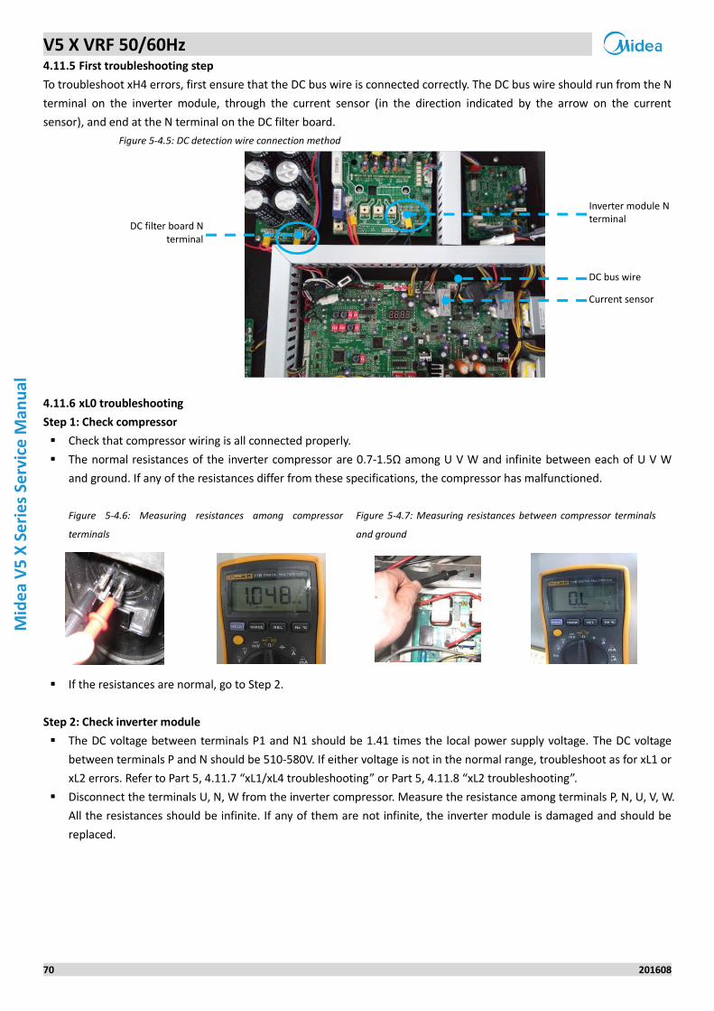
V5 X VRF 50/60Hz
70 201608
Mid
ea
V5
X S
eri
es
Serv
ice
Man
ual
First troubleshooting step 4.11.5
To troubleshoot xH4 errors, first ensure that the DC bus wire is connected correctly. The DC bus wire should run from the N
terminal on the inverter module, through the current sensor (in the direction indicated by the arrow on the current
sensor), and end at the N terminal on the DC filter board.
Figure 5-4.5: DC detection wire connection method
xL0 troubleshooting 4.11.6
Step 1: Check compressor
Check that compressor wiring is all connected properly.
The normal resistances of the inverter compressor are 0.7-1.5Ω among U V W and infinite between each of U V W
and ground. If any of the resistances differ from these specifications, the compressor has malfunctioned.
Figure 5-4.6: Measuring resistances among compressor
terminals
Figure 5-4.7: Measuring resistances between compressor terminals
and ground
If the resistances are normal, go to Step 2.
Step 2: Check inverter module
The DC voltage between terminals P1 and N1 should be 1.41 times the local power supply voltage. The DC voltage
between terminals P and N should be 510-580V. If either voltage is not in the normal range, troubleshoot as for xL1 or
xL2 errors. Refer to Part 5, 4.11.7 “xL1/xL4 troubleshooting” or Part 5, 4.11.8 “xL2 troubleshooting”.
Disconnect the terminals U, N, W from the inverter compressor. Measure the resistance among terminals P, N, U, V, W.
All the resistances should be infinite. If any of them are not infinite, the inverter module is damaged and should be
replaced.
Inverter module N terminal
DC bus wire
Current sensor
DC filter board N terminal
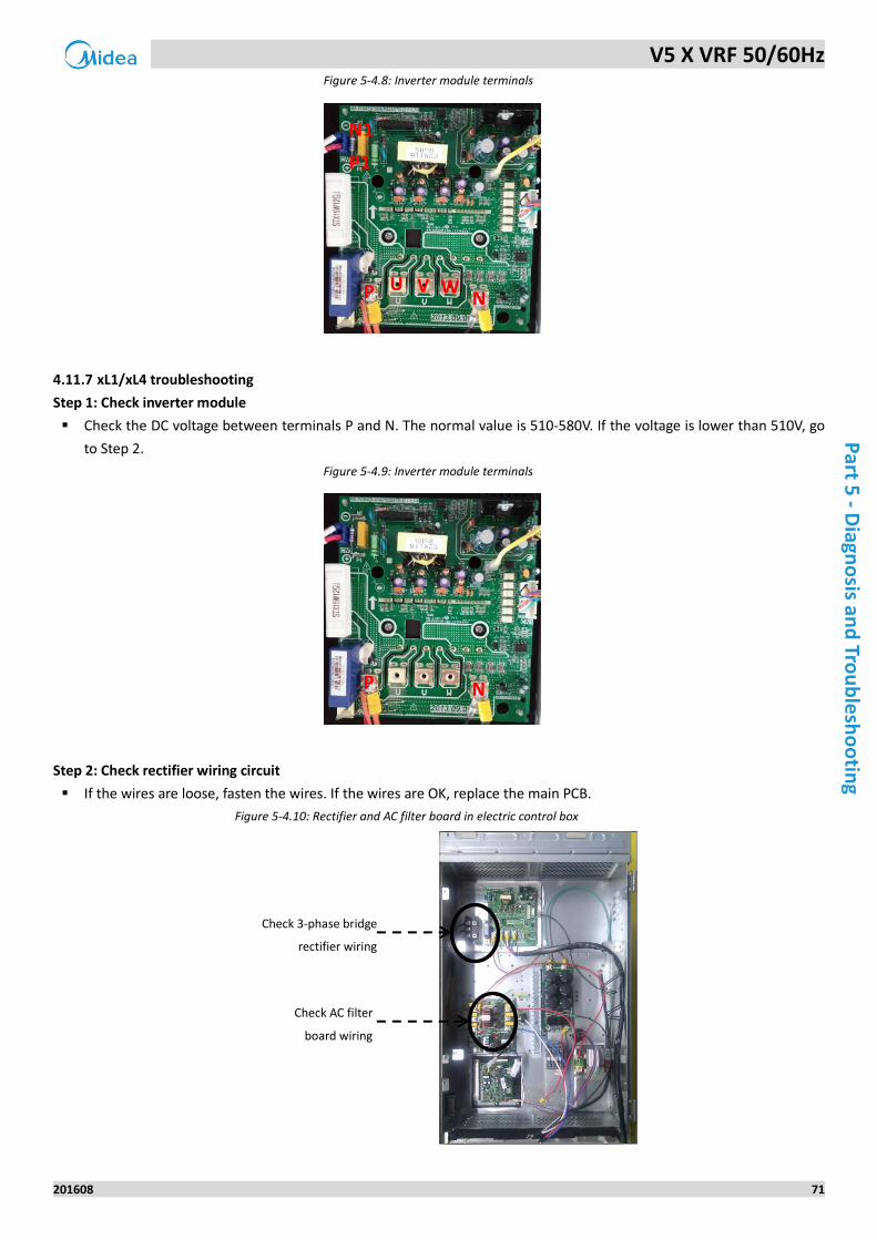
V5 X VRF 50/60Hz
201608 71
Part 5
- Diagn
osis an
d Tro
ub
lesh
oo
ting
Figure 5-4.8: Inverter module terminals
xL1/xL4 troubleshooting 4.11.7
Step 1: Check inverter module
Check the DC voltage between terminals P and N. The normal value is 510-580V. If the voltage is lower than 510V, go
to Step 2.
Figure 5-4.9: Inverter module terminals
Step 2: Check rectifier wiring circuit
If the wires are loose, fasten the wires. If the wires are OK, replace the main PCB.
Figure 5-4.10: Rectifier and AC filter board in electric control box
P1
N1
P N U V W
P N
Check 3-phase bridge
rectifier wiring
Check AC filter
board wiring
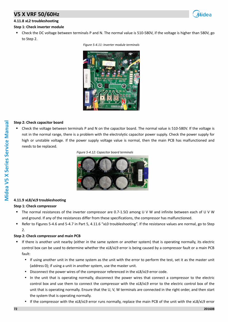
V5 X VRF 50/60Hz
72 201608
Mid
ea
V5
X S
eri
es
Serv
ice
Man
ual
xL2 troubleshooting 4.11.8
Step 1: Check inverter module
Check the DC voltage between terminals P and N. The normal value is 510-580V, if the voltage is higher than 580V, go
to Step 2.
Figure 5-4.11: Inverter module terminals
Step 2: Check capacitor board
Check the voltage between terminals P and N on the capacitor board. The normal value is 510-580V. If the voltage is
not in the normal range, there is a problem with the electrolytic capacitor power supply. Check the power supply for
high or unstable voltage. If the power supply voltage value is normal, then the main PCB has malfunctioned and
needs to be replaced.
Figure 5-4.12: Capacitor board terminals
xL8/xL9 troubleshooting 4.11.9
Step 1: Check compressor
The normal resistances of the inverter compressor are 0.7-1.5Ω among U V W and infinite between each of U V W
and ground. If any of the resistances differ from these specifications, the compressor has malfunctioned.
Refer to Figures 5-4.6 and 5-4.7 in Part 5, 4.11.6 “xL0 troubleshooting”. If the resistance values are normal, go to Step
2.
Step 2: Check compressor and main PCB
If there is another unit nearby (either in the same system or another system) that is operating normally, its electric
control box can be used to determine whether the xL8/xL9 error is being caused by a compressor fault or a main PCB
fault:
If using another unit in the same system as the unit with the error to perform the test, set it as the master unit
(address 0); if using a unit in another system, use the master unit.
Disconnect the power wires of the compressor referenced in the xL8/xL9 error code.
In the unit that is operating normally, disconnect the power wires that connect a compressor to the electric
control box and use them to connect the compressor with the xL8/xL9 error to the electric control box of the
unit that is operating normally. Ensure that the U, V, W terminals are connected in the right order, and then start
the system that is operating normally.
If the compressor with the xL8/xL9 error runs normally, replace the main PCB of the unit with the xL8/xL9 error
P N
P
N
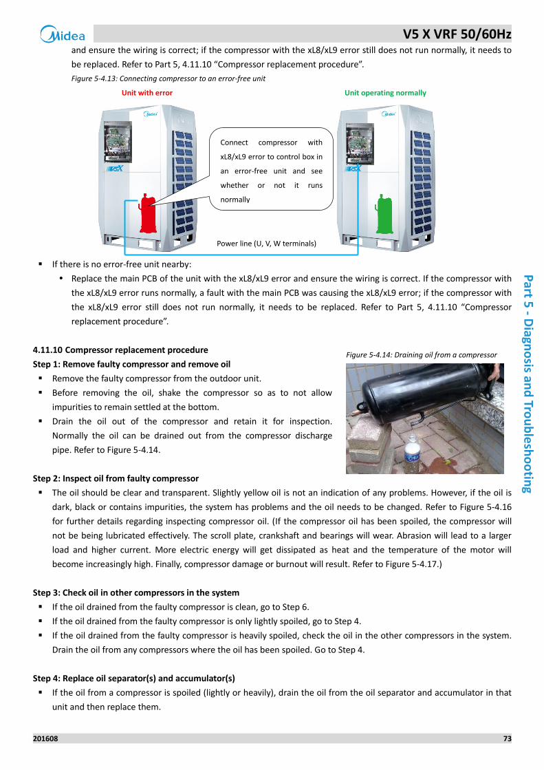
V5 X VRF 50/60Hz
201608 73
Part 5
- Diagn
osis an
d Tro
ub
lesh
oo
ting
and ensure the wiring is correct; if the compressor with the xL8/xL9 error still does not run normally, it needs to
be replaced. Refer to Part 5, 4.11.10 “Compressor replacement procedure”.
Figure 5-4.13: Connecting compressor to an error-free unit
Unit with error Unit operating normally
If there is no error-free unit nearby:
Replace the main PCB of the unit with the xL8/xL9 error and ensure the wiring is correct. If the compressor with
the xL8/xL9 error runs normally, a fault with the main PCB was causing the xL8/xL9 error; if the compressor with
the xL8/xL9 error still does not run normally, it needs to be replaced. Refer to Part 5, 4.11.10 “Compressor
replacement procedure”.
Compressor replacement procedure 4.11.10
Step 1: Remove faulty compressor and remove oil
Remove the faulty compressor from the outdoor unit.
Before removing the oil, shake the compressor so as to not allow
impurities to remain settled at the bottom.
Drain the oil out of the compressor and retain it for inspection.
Normally the oil can be drained out from the compressor discharge
pipe. Refer to Figure 5-4.14.
Step 2: Inspect oil from faulty compressor
The oil should be clear and transparent. Slightly yellow oil is not an indication of any problems. However, if the oil is
dark, black or contains impurities, the system has problems and the oil needs to be changed. Refer to Figure 5-4.16
for further details regarding inspecting compressor oil. (If the compressor oil has been spoiled, the compressor will
not be being lubricated effectively. The scroll plate, crankshaft and bearings will wear. Abrasion will lead to a larger
load and higher current. More electric energy will get dissipated as heat and the temperature of the motor will
become increasingly high. Finally, compressor damage or burnout will result. Refer to Figure 5-4.17.)
Step 3: Check oil in other compressors in the system
If the oil drained from the faulty compressor is clean, go to Step 6.
If the oil drained from the faulty compressor is only lightly spoiled, go to Step 4.
If the oil drained from the faulty compressor is heavily spoiled, check the oil in the other compressors in the system.
Drain the oil from any compressors where the oil has been spoiled. Go to Step 4.
Step 4: Replace oil separator(s) and accumulator(s)
If the oil from a compressor is spoiled (lightly or heavily), drain the oil from the oil separator and accumulator in that
unit and then replace them.
Figure 5-4.14: Draining oil from a compressor
Power line (U, V, W terminals)
Connect compressor with
xL8/xL9 error to control box in
an error-free unit and see
whether or not it runs
normally
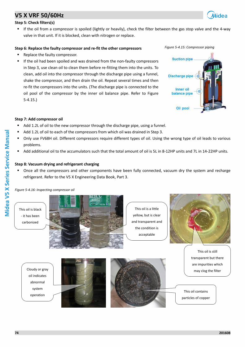
V5 X VRF 50/60Hz
74 201608
Mid
ea
V5
X S
eri
es
Serv
ice
Man
ual
Step 5: Check filters(s)
If the oil from a compressor is spoiled (lightly or heavily), check the filter between the gas stop valve and the 4-way
valve in that unit. If it is blocked, clean with nitrogen or replace.
Step 6: Replace the faulty compressor and re-fit the other compressors
Replace the faulty compressor.
If the oil had been spoiled and was drained from the non-faulty compressors
in Step 3, use clean oil to clean them before re-fitting them into the units. To
clean, add oil into the compressor through the discharge pipe using a funnel,
shake the compressor, and then drain the oil. Repeat several times and then
re-fit the compressors into the units. (The discharge pipe is connected to the
oil pool of the compressor by the inner oil balance pipe. Refer to Figure
5-4.15.)
Step 7: Add compressor oil
Add 1.2L of oil to the new compressor through the discharge pipe, using a funnel.
Add 1.2L of oil to each of the compressors from which oil was drained in Step 3.
Only use FV68H oil. Different compressors require different types of oil. Using the wrong type of oil leads to various
problems.
Add additional oil to the accumulators such that the total amount of oil is 5L in 8-12HP units and 7L in 14-22HP units.
Step 8: Vacuum drying and refrigerant charging
Once all the compressors and other components have been fully connected, vacuum dry the system and recharge
refrigerant. Refer to the V5 X Engineering Data Book, Part 3.
Figure 5-4.16: Inspecting compressor oil
Figure 5-4.15: Compressor piping
This oil is black
- it has been
carbonized
This oil is a little
yellow, but is clear
and transparent and
the condition is
acceptable
This oil is still
transparent but there
are impurities which
may clog the filter Cloudy or gray
oil indicates
abnormal
system
operation This oil contains
particles of copper
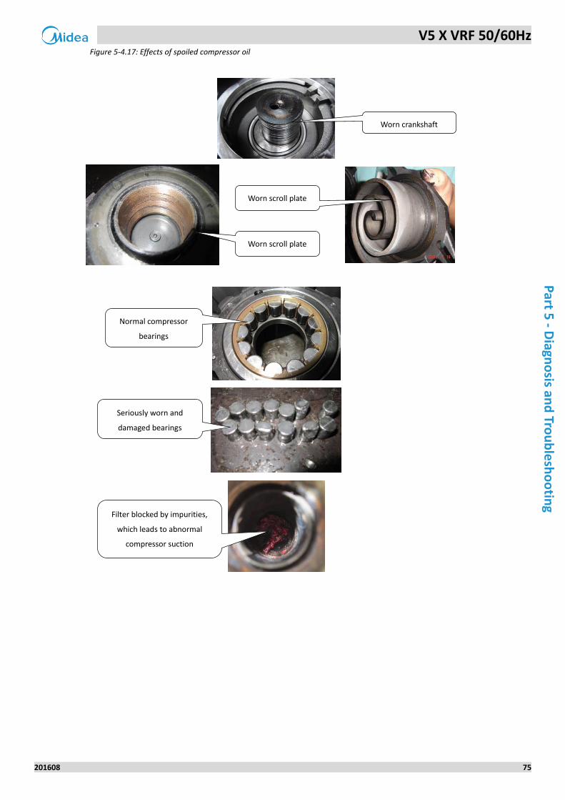
V5 X VRF 50/60Hz
201608 75
Part 5
- Diagn
osis an
d Tro
ub
lesh
oo
ting
Figure 5-4.17: Effects of spoiled compressor oil
Worn scroll plate
Worn scroll plate
Normal compressor
bearings
Seriously worn and
damaged bearings
Filter blocked by impurities,
which leads to abnormal
compressor suction
Worn crankshaft
V5 X VRF 50/60Hz
76 201608
Mid
ea
V5
X S
eri
es
Serv
ice
Man
ual
4.12 H7 Troubleshooting
Digital display output 4.12.1
Description 4.12.2
Number of indoor units detected by master unit not same as number set on main PCB.
All units stop running.
Error code is only displayed on the master unit.
Possible causes 4.12.3
Number of indoor units set on main PCB not same as actual number of indoor units.
Some indoor units are powered off.
Communication wires between indoor and outdoor units not connected properly.
Indoor unit PCB damaged.
Indoor unit without address or indoor unit address duplicated.
Main PCB damaged.
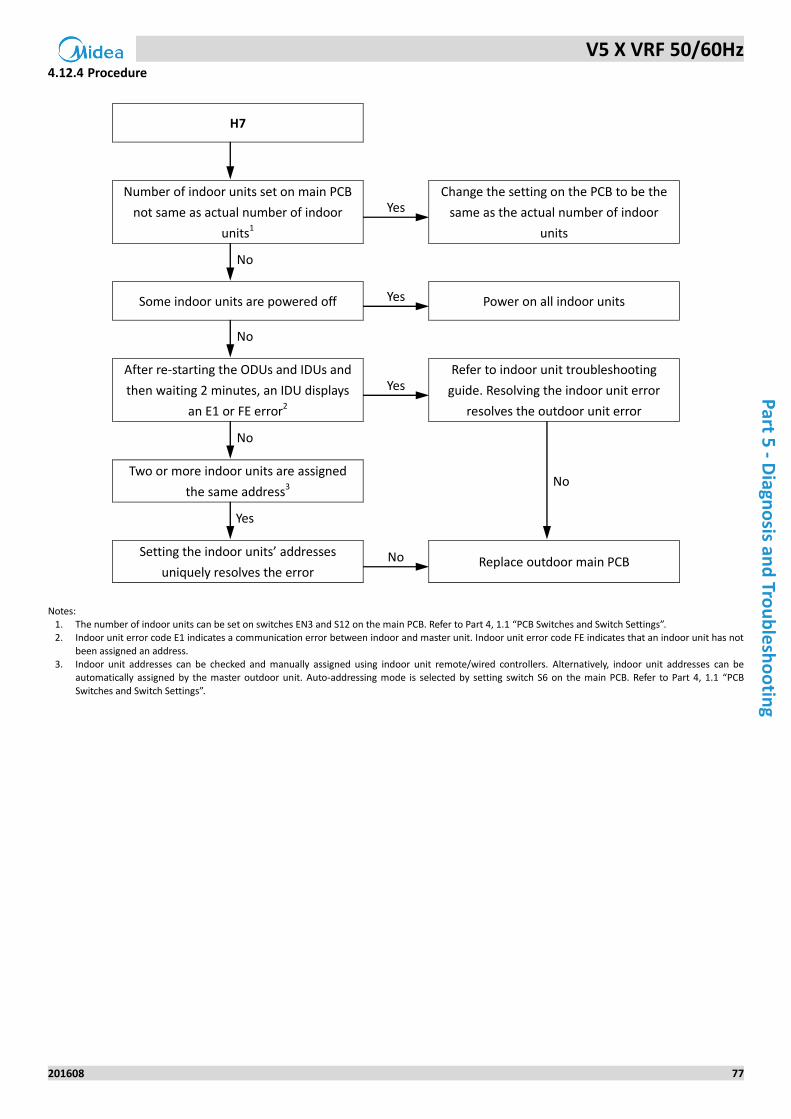
V5 X VRF 50/60Hz
201608 77
Part 5
- Diagn
osis an
d Tro
ub
lesh
oo
ting
Procedure 4.12.4
H7
Number of indoor units set on main PCB
not same as actual number of indoor
units1
Yes Change the setting on the PCB to be the
same as the actual number of indoor
units
No
Some indoor units are powered off Yes Power on all indoor units
No
After re-starting the ODUs and IDUs and
then waiting 2 minutes, an IDU displays
an E1 or FE error2
Yes Refer to indoor unit troubleshooting
guide. Resolving the indoor unit error
resolves the outdoor unit error
No
Two or more indoor units are assigned
the same address3 No
Yes
Setting the indoor units’ addresses
uniquely resolves the error No Replace outdoor main PCB
Notes:
1. The number of indoor units can be set on switches EN3 and S12 on the main PCB. Refer to Part 4, 1.1 “PCB Switches and Switch Settings”. 2. Indoor unit error code E1 indicates a communication error between indoor and master unit. Indoor unit error code FE indicates that an indoor unit has not
been assigned an address. 3. Indoor unit addresses can be checked and manually assigned using indoor unit remote/wired controllers. Alternatively, indoor unit addresses can be
automatically assigned by the master outdoor unit. Auto-addressing mode is selected by setting switch S6 on the main PCB. Refer to Part 4, 1.1 “PCB
Switches and Switch Settings”.
V5 X VRF 50/60Hz
78 201608
Mid
ea
V5
X S
eri
es
Serv
ice
Man
ual
4.13 H8 Troubleshooting
Digital display output 4.13.1
Description 4.13.2
Discharge pipe low pressure protection. When the discharge pressure falls below 0.3MPa, the system displays H8
protection and all units stop running. When the discharge pressure returns to normal, H8 is removed and normal
operation resumes.
Error code is only displayed on the unit with the error.
Possible causes 4.13.3
Outdoor unit stop valves are closed.
Pressure sensor not connected properly or has malfunctioned.
Insufficient refrigerant.
Low pressure side blockage.
Poor evaporator heat exchange.
Main PCB damaged.
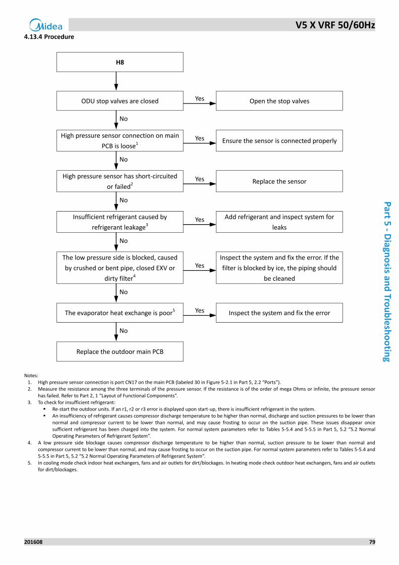
V5 X VRF 50/60Hz
201608 79
Part 5
- Diagn
osis an
d Tro
ub
lesh
oo
ting
Procedure 4.13.4
H8
ODU stop valves are closed Yes Open the stop valves
No
High pressure sensor connection on main
PCB is loose1 Yes Ensure the sensor is connected properly
No
High pressure sensor has short-circuited
or failed2 Yes Replace the sensor
No
Insufficient refrigerant caused by
refrigerant leakage3 Yes Add refrigerant and inspect system for
leaks
No
The low pressure side is blocked, caused
by crushed or bent pipe, closed EXV or
dirty filter4
Yes Inspect the system and fix the error. If the
filter is blocked by ice, the piping should
be cleaned
No
The evaporator heat exchange is poor5 Yes Inspect the system and fix the error
No
Replace the outdoor main PCB
Notes:
1. High pressure sensor connection is port CN17 on the main PCB (labeled 30 in Figure 5-2.1 in Part 5, 2.2 “Ports”). 2. Measure the resistance among the three terminals of the pressure sensor. If the resistance is of the order of mega Ohms or infinite, the pressure sensor
has failed. Refer to Part 2, 1 “Layout of Functional Components”.
3. To check for insufficient refrigerant: Re-start the outdoor units. If an r1, r2 or r3 error is displayed upon start-up, there is insufficient refrigerant in the system. An insufficiency of refrigerant causes compressor discharge temperature to be higher than normal, discharge and suction pressures to be lower than
normal and compressor current to be lower than normal, and may cause frosting to occur on the suction pipe. These issues disappear once sufficient refrigerant has been charged into the system. For normal system parameters refer to Tables 5-5.4 and 5-5.5 in Part 5, 5.2 “5.2 Normal Operating Parameters of Refrigerant System”.
4. A low pressure side blockage causes compressor discharge temperature to be higher than normal, suction pressure to be lower than normal and compressor current to be lower than normal, and may cause frosting to occur on the suction pipe. For normal system parameters refer to Tables 5-5.4 and 5-5.5 in Part 5, 5.2 “5.2 Normal Operating Parameters of Refrigerant System”.
5. In cooling mode check indoor heat exchangers, fans and air outlets for dirt/blockages. In heating mode check outdoor heat exchangers, fans and air outlets for dirt/blockages.
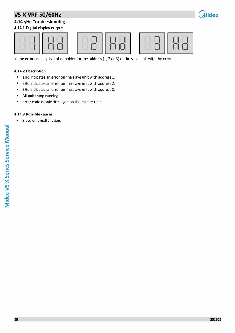
V5 X VRF 50/60Hz
80 201608
Mid
ea
V5
X S
eri
es
Serv
ice
Man
ual
4.14 yHd Troubleshooting
Digital display output 4.14.1
In the error code, 'y' is a placeholder for the address (1, 2 or 3) of the slave unit with the error.
Description 4.14.2
1Hd indicates an error on the slave unit with address 1.
2Hd indicates an error on the slave unit with address 2.
3Hd indicates an error on the slave unit with address 3.
All units stop running.
Error code is only displayed on the master unit.
Possible causes 4.14.3
Slave unit malfunction.
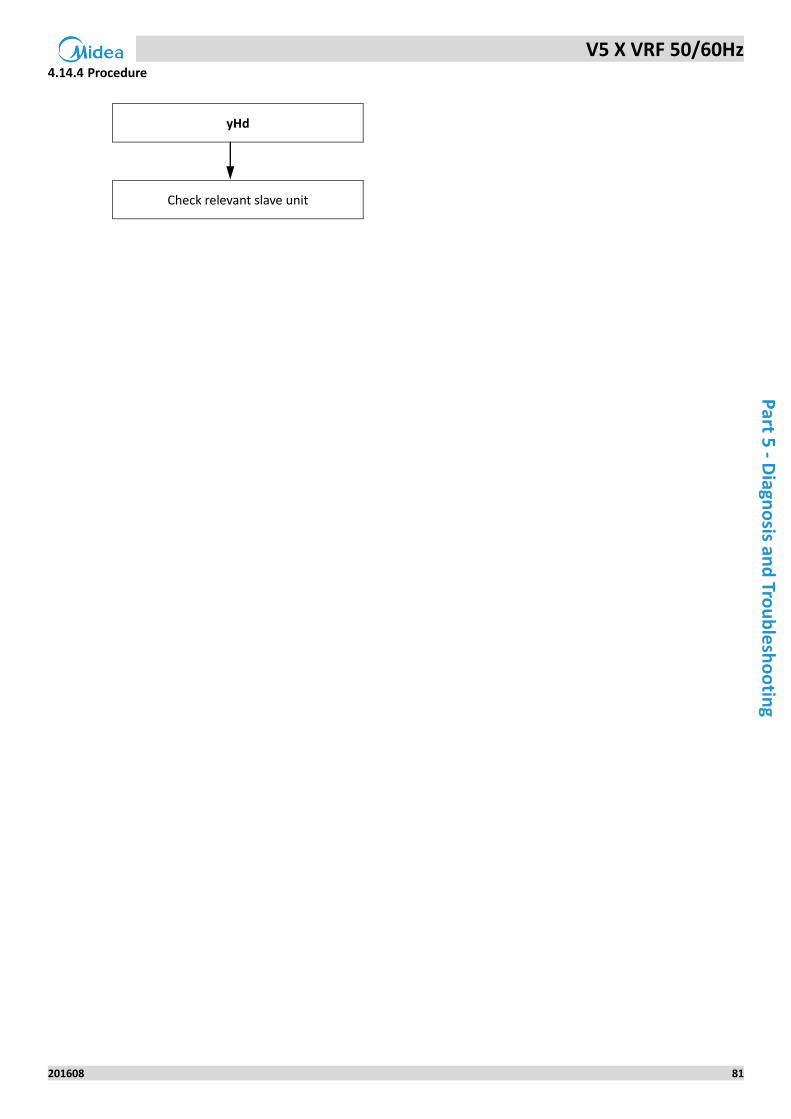
V5 X VRF 50/60Hz
201608 81
Part 5
- Diagn
osis an
d Tro
ub
lesh
oo
ting
Procedure 4.14.4
yHd
Check relevant slave unit
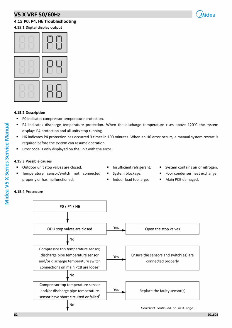
V5 X VRF 50/60Hz
82 201608
Mid
ea
V5
X S
eri
es
Serv
ice
Man
ual
4.15 P0, P4, H6 Troubleshooting
Digital display output 4.15.1
Description 4.15.2
P0 indicates compressor temperature protection.
P4 indicates discharge temperature protection. When the discharge temperature rises above 120°C the system
displays P4 protection and all units stop running.
H6 indicates P4 protection has occurred 3 times in 100 minutes. When an H6 error occurs, a manual system restart is
required before the system can resume operation.
Error code is only displayed on the unit with the error..
Possible causes 4.15.3
Outdoor unit stop valves are closed.
Temperature sensor/switch not connected
properly or has malfunctioned.
Insufficient refrigerant.
System blockage.
Indoor load too large.
System contains air or nitrogen.
Poor condenser heat exchange.
Main PCB damaged.
Procedure 4.15.4
P0 / P4 / H6
ODU stop valves are closed Yes Open the stop valves
No
Compressor top temperature sensor,
discharge pipe temperature sensor
and/or discharge temperature switch
connections on main PCB are loose1
Yes Ensure the sensors and switch(es) are
connected properly
No
Compressor top temperature sensor
and/or discharge pipe temperature
sensor have short circuited or failed2
Yes Replace the faulty sensor(s)
No Flowchart continued on next page …
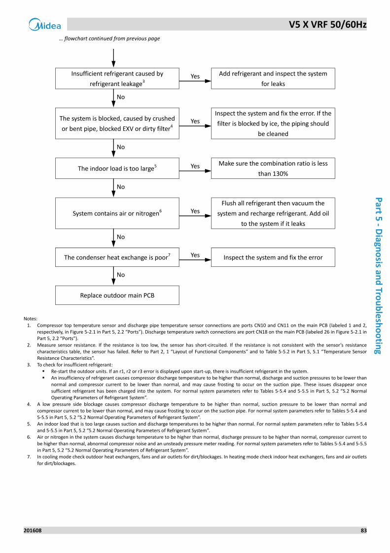
V5 X VRF 50/60Hz
201608 83
Part 5
- Diagn
osis an
d Tro
ub
lesh
oo
ting
… flowchart continued from previous page
Insufficient refrigerant caused by
refrigerant leakage3 Yes Add refrigerant and inspect the system
for leaks
No
The system is blocked, caused by crushed
or bent pipe, blocked EXV or dirty filter4 Yes
Inspect the system and fix the error. If the
filter is blocked by ice, the piping should
be cleaned
No
The indoor load is too large5 Yes Make sure the combination ratio is less
than 130%
No
System contains air or nitrogen6 Yes Flush all refrigerant then vacuum the
system and recharge refrigerant. Add oil
to the system if it leaks
No
The condenser heat exchange is poor7 Yes Inspect the system and fix the error
No
Replace outdoor main PCB
Notes:
1. Compressor top temperature sensor and discharge pipe temperature sensor connections are ports CN10 and CN11 on the main PCB (labeled 1 and 2, respectively, in Figure 5-2.1 in Part 5, 2.2 “Ports”). Discharge temperature switch connections are port CN18 on the main PCB (labeled 26 in Figure 5-2.1 in Part 5, 2.2 “Ports”).
2. Measure sensor resistance. If the resistance is too low, the sensor has short-circuited. If the resistance is not consistent with the sensor’s resistance characteristics table, the sensor has failed. Refer to Part 2, 1 “Layout of Functional Components” and to Table 5-5.2 in Part 5, 5.1 “Temperature Sensor Resistance Characteristics”.
3. To check for insufficient refrigerant: Re-start the outdoor units. If an r1, r2 or r3 error is displayed upon start-up, there is insufficient refrigerant in the system. An insufficiency of refrigerant causes compressor discharge temperature to be higher than normal, discharge and suction pressures to be lower than
normal and compressor current to be lower than normal, and may cause frosting to occur on the suction pipe. These issues disappear once sufficient refrigerant has been charged into the system. For normal system parameters refer to Tables 5-5.4 and 5-5.5 in Part 5, 5.2 “5.2 Normal Operating Parameters of Refrigerant System”.
4. A low pressure side blockage causes compressor discharge temperature to be higher than normal, suction pressure to be lower than normal and compressor current to be lower than normal, and may cause frosting to occur on the suction pipe. For normal system parameters refer to Tables 5-5.4 and 5-5.5 in Part 5, 5.2 “5.2 Normal Operating Parameters of Refrigerant System”.
5. An indoor load that is too large causes suction and discharge temperatures to be higher than normal. For normal system parameters refer to Tables 5-5.4 and 5-5.5 in Part 5, 5.2 “5.2 Normal Operating Parameters of Refrigerant System”.
6. Air or nitrogen in the system causes discharge temperature to be higher than normal, discharge pressure to be higher than normal, compressor current to
be higher than normal, abnormal compressor noise and an unsteady pressure meter reading. For normal system parameters refer to Tables 5-5.4 and 5-5.5 in Part 5, 5.2 “5.2 Normal Operating Parameters of Refrigerant System”.
7. In cooling mode check outdoor heat exchangers, fans and air outlets for dirt/blockages. In heating mode check indoor heat exchangers, fans and air outlets
for dirt/blockages.
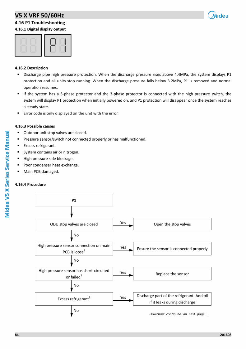
V5 X VRF 50/60Hz
84 201608
Mid
ea
V5
X S
eri
es
Serv
ice
Man
ual
4.16 P1 Troubleshooting
Digital display output 4.16.1
Description 4.16.2
Discharge pipe high pressure protection. When the discharge pressure rises above 4.4MPa, the system displays P1
protection and all units stop running. When the discharge pressure falls below 3.2MPa, P1 is removed and normal
operation resumes.
If the system has a 3-phase protector and the 3-phase protector is connected with the high pressure switch, the
system will display P1 protection when initially powered on, and P1 protection will disappear once the system reaches
a steady state.
Error code is only displayed on the unit with the error.
Possible causes 4.16.3
Outdoor unit stop valves are closed.
Pressure sensor/switch not connected properly or has malfunctioned.
Excess refrigerant.
System contains air or nitrogen.
High pressure side blockage.
Poor condenser heat exchange.
Main PCB damaged.
Procedure 4.16.4
P1
ODU stop valves are closed Yes Open the stop valves
No
High pressure sensor connection on main
PCB is loose1 Yes Ensure the sensor is connected properly
No
High pressure sensor has short-circuited
or failed2 Yes Replace the sensor
No
Excess refrigerant3 Yes Discharge part of the refrigerant. Add oil
if it leaks during discharge
No Flowchart continued on next page …
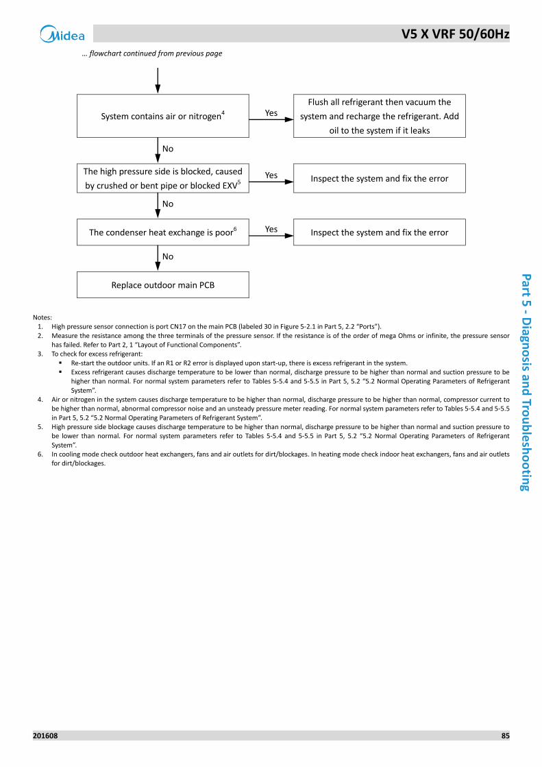
V5 X VRF 50/60Hz
201608 85
Part 5
- Diagn
osis an
d Tro
ub
lesh
oo
ting
… flowchart continued from previous page
System contains air or nitrogen4 Yes Flush all refrigerant then vacuum the
system and recharge the refrigerant. Add
oil to the system if it leaks
No
The high pressure side is blocked, caused
by crushed or bent pipe or blocked EXV5 Yes Inspect the system and fix the error
No
The condenser heat exchange is poor6 Yes Inspect the system and fix the error
No
Replace outdoor main PCB
Notes:
1. High pressure sensor connection is port CN17 on the main PCB (labeled 30 in Figure 5-2.1 in Part 5, 2.2 “Ports”).
2. Measure the resistance among the three terminals of the pressure sensor. If the resistance is of the order of mega Ohms or infinite, the pressure sensor has failed. Refer to Part 2, 1 “Layout of Functional Components”.
3. To check for excess refrigerant:
Re-start the outdoor units. If an R1 or R2 error is displayed upon start-up, there is excess refrigerant in the system. Excess refrigerant causes discharge temperature to be lower than normal, discharge pressure to be higher than normal and suction pressure to be
higher than normal. For normal system parameters refer to Tables 5-5.4 and 5-5.5 in Part 5, 5.2 “5.2 Normal Operating Parameters of Refrigerant
System”. 4. Air or nitrogen in the system causes discharge temperature to be higher than normal, discharge pressure to be higher than normal, compressor current to
be higher than normal, abnormal compressor noise and an unsteady pressure meter reading. For normal system parameters refer to Tables 5-5.4 and 5-5.5
in Part 5, 5.2 “5.2 Normal Operating Parameters of Refrigerant System”. 5. High pressure side blockage causes discharge temperature to be higher than normal, discharge pressure to be higher than normal and suction pressure to
be lower than normal. For normal system parameters refer to Tables 5-5.4 and 5-5.5 in Part 5, 5.2 “5.2 Normal Operating Parameters of Refrigerant
System”. 6. In cooling mode check outdoor heat exchangers, fans and air outlets for dirt/blockages. In heating mode check indoor heat exchangers, fans and air outlets
for dirt/blockages.
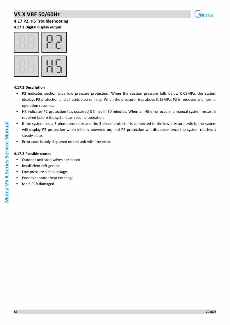
V5 X VRF 50/60Hz
86 201608
Mid
ea
V5
X S
eri
es
Serv
ice
Man
ual
4.17 P2, H5 Troubleshooting
Digital display output 4.17.1
Description 4.17.2
P2 indicates suction pipe low pressure protection. When the suction pressure falls below 0.05MPa, the system
displays P2 protection and all units stop running. When the pressure rises above 0.15MPa, P2 is removed and normal
operation resumes.
H5 indicates P2 protection has occurred 3 times in 60 minutes. When an H5 error occurs, a manual system restart is
required before the system can resume operation.
If the system has a 3-phase protector and the 3-phase protector is connected to the low pressure switch, the system
will display P2 protection when initially powered on, and P2 protection will disappear once the system reaches a
steady state.
Error code is only displayed on the unit with the error.
Possible causes 4.17.3
Outdoor unit stop valves are closed.
Insufficient refrigerant.
Low pressure side blockage.
Poor evaporator heat exchange.
Main PCB damaged.
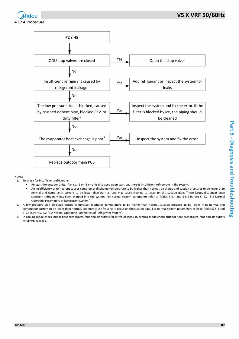
V5 X VRF 50/60Hz
201608 87
Part 5
- Diagn
osis an
d Tro
ub
lesh
oo
ting
Procedure 4.17.4
P2 / H5
ODU stop valves are closed Yes Open the stop valves
No
Insufficient refrigerant caused by
refrigerant leakage1 Yes Add refrigerant or inspect the system for
leaks
No
The low pressure side is blocked, caused
by crushed or bent pipe, blocked EXV, or
dirty filter2
Yes Inspect the system and fix the error. If the
filter is blocked by ice, the piping should
be cleaned
No
The evaporator heat exchange is poor5 Yes Inspect the system and fix the error
No
Replace outdoor main PCB
Notes:
1. To check for insufficient refrigerant: Re-start the outdoor units. If an r1, r2 or r3 error is displayed upon start-up, there is insufficient refrigerant in the system. An insufficiency of refrigerant causes compressor discharge temperature to be higher than normal, discharge and suction pressures to be lower than
normal and compressor current to be lower than normal, and may cause frosting to occur on the suction pipe. These issues disappear once sufficient refrigerant has been charged into the system. For normal system parameters refer to Tables 5-5.4 and 5-5.5 in Part 5, 5.2 “5.2 Normal Operating Parameters of Refrigerant System”.
2. A low pressure side blockage causes compressor discharge temperature to be higher than normal, suction pressure to be lower than normal and compressor current to be lower than normal, and may cause frosting to occur on the suction pipe. For normal system parameters refer to Tables 5-5.4 and 5-5.5 in Part 5, 5.2 “5.2 Normal Operating Parameters of Refrigerant System”.
3. In cooling mode check indoor heat exchangers, fans and air outlets for dirt/blockages. In heating mode check outdoor heat exchangers, fans and air outlets for dirt/blockages.
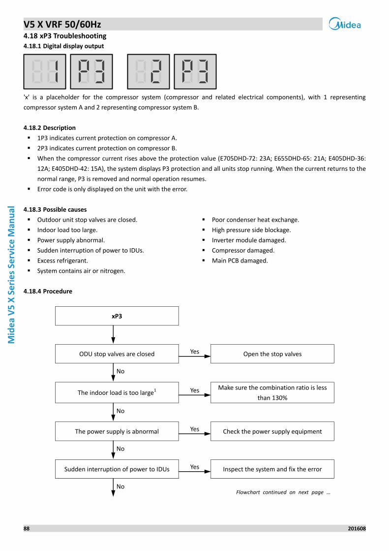
V5 X VRF 50/60Hz
88 201608
Mid
ea
V5
X S
eri
es
Serv
ice
Man
ual
4.18 xP3 Troubleshooting
Digital display output 4.18.1
'x' is a placeholder for the compressor system (compressor and related electrical components), with 1 representing
compressor system A and 2 representing compressor system B.
Description 4.18.2
1P3 indicates current protection on compressor A.
2P3 indicates current protection on compressor B.
When the compressor current rises above the protection value (E705DHD-72: 23A; E655DHD-65: 21A; E405DHD-36:
12A; E405DHD-42: 15A), the system displays P3 protection and all units stop running. When the current returns to the
normal range, P3 is removed and normal operation resumes.
Error code is only displayed on the unit with the error.
Possible causes 4.18.3
Outdoor unit stop valves are closed.
Indoor load too large.
Power supply abnormal.
Sudden interruption of power to IDUs.
Excess refrigerant.
System contains air or nitrogen.
Poor condenser heat exchange.
High pressure side blockage.
Inverter module damaged.
Compressor damaged.
Main PCB damaged.
Procedure 4.18.4
xP3
ODU stop valves are closed Yes Open the stop valves
No
The indoor load is too large1 Yes Make sure the combination ratio is less
than 130%
No
The power supply is abnormal Yes Check the power supply equipment
No
Sudden interruption of power to IDUs Yes Inspect the system and fix the error
No Flowchart continued on next page …
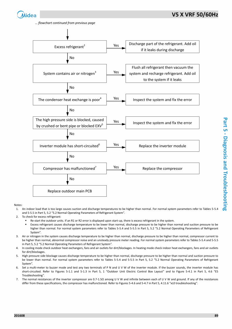
V5 X VRF 50/60Hz
201608 89
Part 5
- Diagn
osis an
d Tro
ub
lesh
oo
ting
… flowchart continued from previous page
Excess refrigerant2 Yes Discharge part of the refrigerant. Add oil
if it leaks during discharge
No
System contains air or nitrogen3 Yes Flush all refrigerant then vacuum the
system and recharge refrigerant. Add oil
to the system if it leaks
No
The condenser heat exchange is poor4 Yes Inspect the system and fix the error
No
The high pressure side is blocked, caused
by crushed or bent pipe or blocked EXV5 Yes Inspect the system and fix the error
No
Inverter module has short-circuited6 Yes Replace the inverter module
No
Compressor has malfunctioned7 Yes Replace the compressor
No
Replace outdoor main PCB
Notes:
1. An indoor load that is too large causes suction and discharge temperatures to be higher than normal. For normal system parameters refer to Tables 5-5.4 and 5-5.5 in Part 5, 5.2 “5.2 Normal Operating Parameters of Refrigerant System”.
2. To check for excess refrigerant:
Re-start the outdoor units. If an R1 or R2 error is displayed upon start-up, there is excess refrigerant in the system. Excess refrigerant causes discharge temperature to be lower than normal, discharge pressure to be higher than normal and suction pressure to be
higher than normal. For normal system parameters refer to Tables 5-5.4 and 5-5.5 in Part 5, 5.2 “5.2 Normal Operating Parameters of Refrigerant
System”. 3. Air or nitrogen in the system causes discharge temperature to be higher than normal, discharge pressure to be higher than normal, compressor current to
be higher than normal, abnormal compressor noise and an unsteady pressure meter reading. For normal system parameters refer to Tables 5-5.4 and 5-5.5
in Part 5, 5.2 “5.2 Normal Operating Parameters of Refrigerant System”. 4. In cooling mode check outdoor heat exchangers, fans and air outlets for dirt/blockages. In heating mode check indoor heat exchangers, fans and air outlets
for dirt/blockages.
5. High pressure side blockage causes discharge temperature to be higher than normal, discharge pressure to be higher than normal and suction pressure to be lower than normal. For normal system parameters refer to Tables 5-5.4 and 5-5.5 in Part 5, 5.2 “5.2 Normal Operating Parameters of Refrigerant System”.
6. Set a multi-meter to buzzer mode and test any two terminals of P N and U V W of the inverter module. If the buzzer sounds, the inverter module has short-circuited. Refer to Figures 5-1.1 and 5-1.3 in Part 5, 1 “Outdoor Unit Electric Control Box Layout” and to Figure 5-4.1 in Part 5, 4.6 “E5 Troubleshooting”.
7. The normal resistances of the inverter compressor are 0.7-1.5Ω among U V W and infinite between each of U V W and ground. If any of the resistances differ from these specifications, the compressor has malfunctioned. Refer to Figures 5-4.6 and 5-4.7 in Part 5, 4.11.6 “xL0 troubleshooting”.
V5 X VRF 50/60Hz
90 201608
Mid
ea
V5
X S
eri
es
Serv
ice
Man
ual
4.19 P5 Troubleshooting
Digital display output 4.19.1
Description 4.19.2
Outdoor heat exchanger temperature protection. When the outdoor heat exchanger temperature rises above 65oC,
the system displays P5 protection and all units stop running. When the temperature returns to the normal range, P5 is
removed and normal operation resumes.
Error code is only displayed on the unit with the error.
Possible causes 4.19.3
Outdoor unit stop valves are closed.
Temperature sensor not connected properly or has malfunctioned.
Indoor load too large.
System contains air or nitrogen.
Poor condenser heat exchange.
High pressure side blockage.
Main PCB damaged.
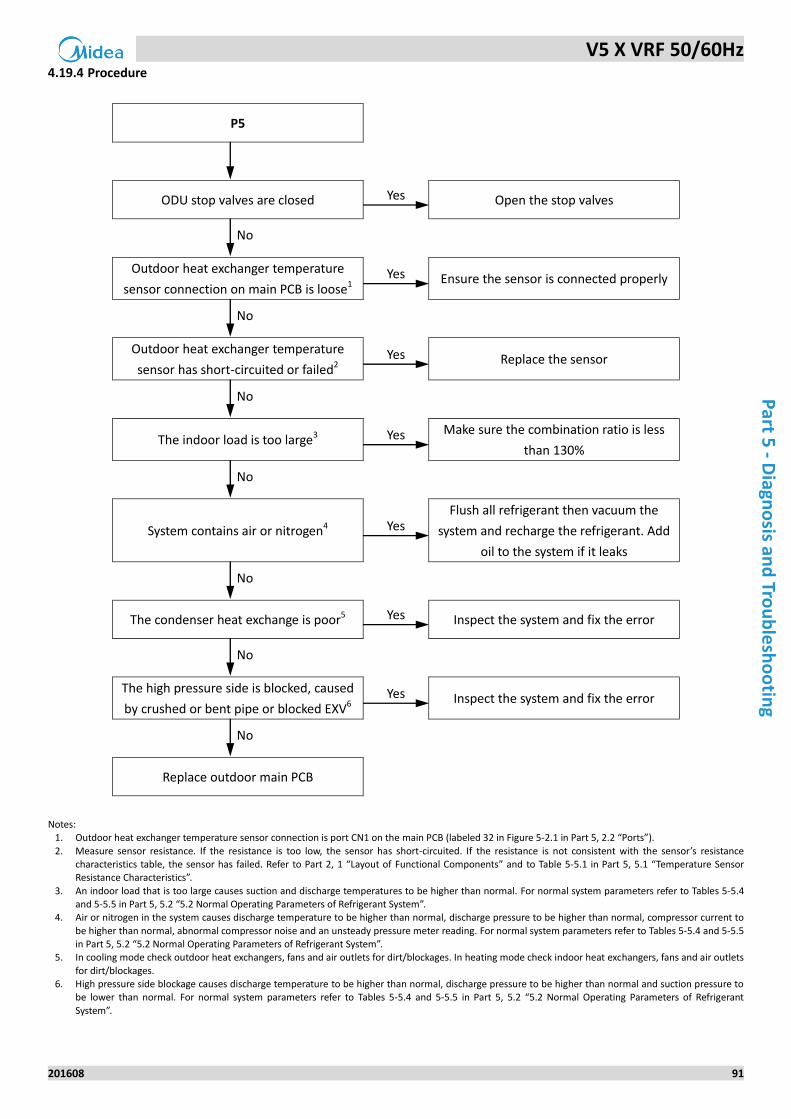
V5 X VRF 50/60Hz
201608 91
Part 5
- Diagn
osis an
d Tro
ub
lesh
oo
ting
Procedure 4.19.4
P5
ODU stop valves are closed Yes Open the stop valves
No
Outdoor heat exchanger temperature
sensor connection on main PCB is loose1 Yes Ensure the sensor is connected properly
No
Outdoor heat exchanger temperature
sensor has short-circuited or failed2 Yes Replace the sensor
No
The indoor load is too large3 Yes Make sure the combination ratio is less
than 130%
No
System contains air or nitrogen4 Yes Flush all refrigerant then vacuum the
system and recharge the refrigerant. Add
oil to the system if it leaks
No
The condenser heat exchange is poor5 Yes Inspect the system and fix the error
No
The high pressure side is blocked, caused
by crushed or bent pipe or blocked EXV6 Yes Inspect the system and fix the error
No
Replace outdoor main PCB
Notes:
1. Outdoor heat exchanger temperature sensor connection is port CN1 on the main PCB (labeled 32 in Figure 5-2.1 in Part 5, 2.2 “Ports”).
2. Measure sensor resistance. If the resistance is too low, the sensor has short-circuited. If the resistance is not consistent with the sensor’s resistance characteristics table, the sensor has failed. Refer to Part 2, 1 “Layout of Functional Components” and to Table 5-5.1 in Part 5, 5.1 “Temperature Sensor Resistance Characteristics”.
3. An indoor load that is too large causes suction and discharge temperatures to be higher than normal. For normal system parameters refer to Tables 5-5.4 and 5-5.5 in Part 5, 5.2 “5.2 Normal Operating Parameters of Refrigerant System”.
4. Air or nitrogen in the system causes discharge temperature to be higher than normal, discharge pressure to be higher than normal, compressor current to
be higher than normal, abnormal compressor noise and an unsteady pressure meter reading. For normal system parameters refer to Tables 5-5.4 and 5-5.5 in Part 5, 5.2 “5.2 Normal Operating Parameters of Refrigerant System”.
5. In cooling mode check outdoor heat exchangers, fans and air outlets for dirt/blockages. In heating mode check indoor heat exchangers, fans and air outlets
for dirt/blockages. 6. High pressure side blockage causes discharge temperature to be higher than normal, discharge pressure to be higher than normal and suction pressure to
be lower than normal. For normal system parameters refer to Tables 5-5.4 and 5-5.5 in Part 5, 5.2 “5.2 Normal Operating Parameters of Refrigerant
System”.
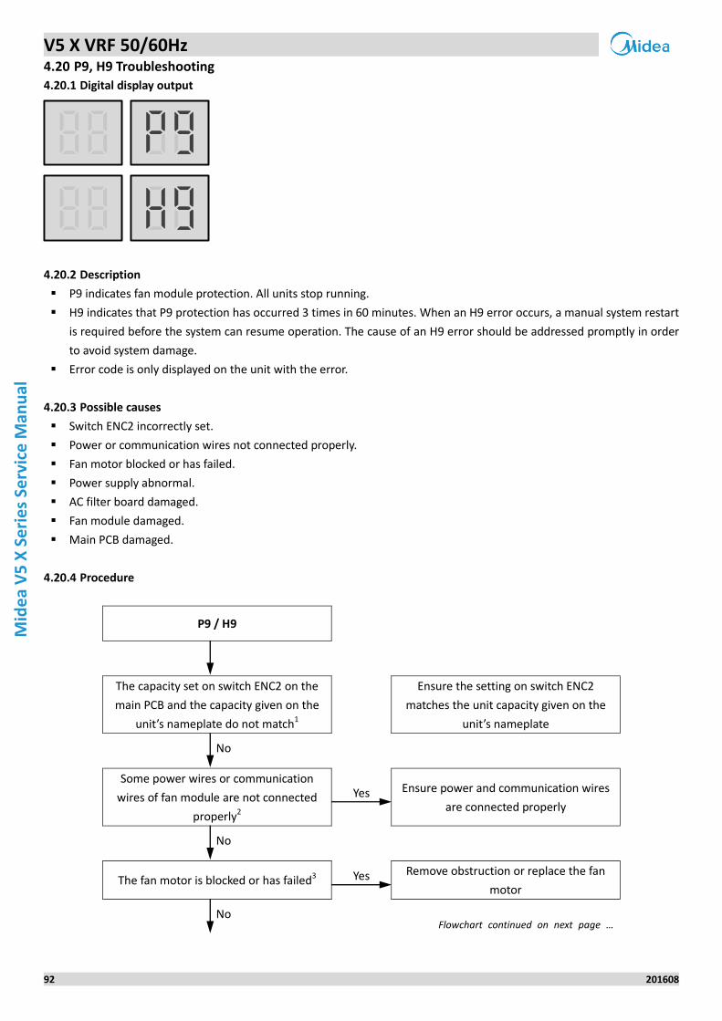
V5 X VRF 50/60Hz
92 201608
Mid
ea
V5
X S
eri
es
Serv
ice
Man
ual
4.20 P9, H9 Troubleshooting
Digital display output 4.20.1
Description 4.20.2
P9 indicates fan module protection. All units stop running.
H9 indicates that P9 protection has occurred 3 times in 60 minutes. When an H9 error occurs, a manual system restart
is required before the system can resume operation. The cause of an H9 error should be addressed promptly in order
to avoid system damage.
Error code is only displayed on the unit with the error.
Possible causes 4.20.3
Switch ENC2 incorrectly set.
Power or communication wires not connected properly.
Fan motor blocked or has failed.
Power supply abnormal.
AC filter board damaged.
Fan module damaged.
Main PCB damaged.
Procedure 4.20.4
P9 / H9
The capacity set on switch ENC2 on the
main PCB and the capacity given on the
unit’s nameplate do not match1
Ensure the setting on switch ENC2
matches the unit capacity given on the
unit’s nameplate
No
Some power wires or communication
wires of fan module are not connected
properly2
Yes Ensure power and communication wires
are connected properly
No
The fan motor is blocked or has failed3 Yes Remove obstruction or replace the fan
motor
No Flowchart continued on next page …
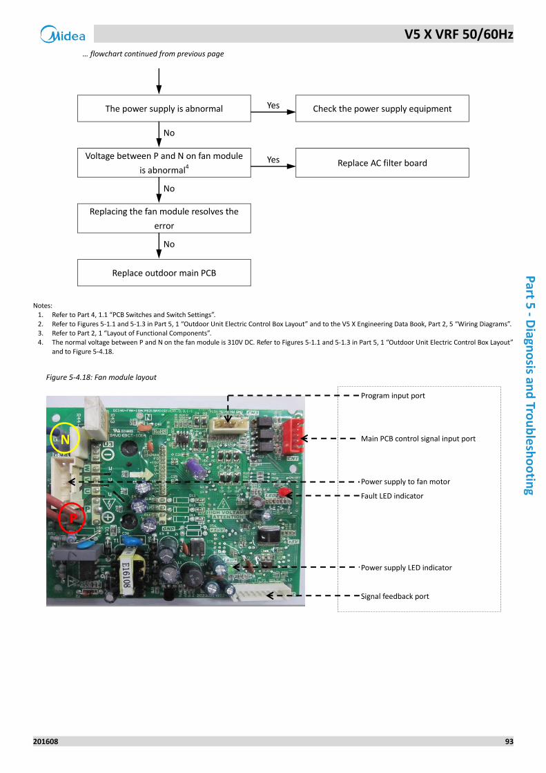
V5 X VRF 50/60Hz
201608 93
Part 5
- Diagn
osis an
d Tro
ub
lesh
oo
ting
… flowchart continued from previous page
The power supply is abnormal Yes Check the power supply equipment
No
Voltage between P and N on fan module
is abnormal4 Yes Replace AC filter board
No
Replacing the fan module resolves the
error
No
Replace outdoor main PCB
Notes:
1. Refer to Part 4, 1.1 “PCB Switches and Switch Settings”.
2. Refer to Figures 5-1.1 and 5-1.3 in Part 5, 1 “Outdoor Unit Electric Control Box Layout” and to the V5 X Engineering Data Book, Part 2, 5 “Wiring Diagrams”. 3. Refer to Part 2, 1 “Layout of Functional Components”. 4. The normal voltage between P and N on the fan module is 310V DC. Refer to Figures 5-1.1 and 5-1.3 in Part 5, 1 “Outdoor Unit Electric Control Box Layout”
and to Figure 5-4.18.
Figure 5-4.18: Fan module layout
P
N
Program input port
Main PCB control signal input port
Power supply to fan motor
Fault LED indicator
Power supply LED indicator
Signal feedback port
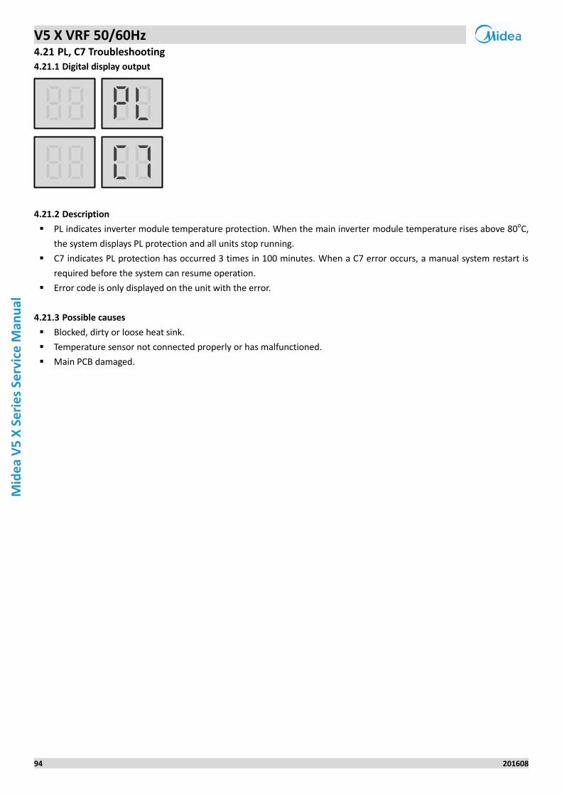
V5 X VRF 50/60Hz
94 201608
Mid
ea
V5
X S
eri
es
Serv
ice
Man
ual
4.21 PL, C7 Troubleshooting
Digital display output 4.21.1
Description 4.21.2
PL indicates inverter module temperature protection. When the main inverter module temperature rises above 80oC,
the system displays PL protection and all units stop running.
C7 indicates PL protection has occurred 3 times in 100 minutes. When a C7 error occurs, a manual system restart is
required before the system can resume operation.
Error code is only displayed on the unit with the error.
Possible causes 4.21.3
Blocked, dirty or loose heat sink.
Temperature sensor not connected properly or has malfunctioned.
Main PCB damaged.
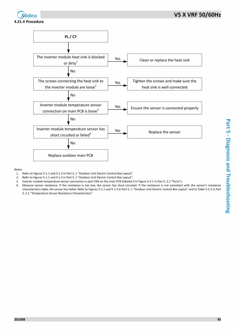
V5 X VRF 50/60Hz
201608 95
Part 5
- Diagn
osis an
d Tro
ub
lesh
oo
ting
Procedure 4.21.4
PL / C7
The inverter module heat sink is blocked
or dirty1 Yes Clean or replace the heat sink
No
The screws connecting the heat sink to
the inverter module are loose2 Yes Tighten the screws and make sure the
heat sink is well-connected
No
Inverter module temperature sensor
connection on main PCB is loose3 Yes Ensure the sensor is connected properly
No
Inverter module temperature sensor has
short circuited or failed4 Yes Replace the sensor
No
Replace outdoor main PCB
Notes:
1. Refer to Figures 5-1.1 and 5-1.3 in Part 5, 1 “Outdoor Unit Electric Control Box Layout”. 2. Refer to Figures 5-1.1 and 5-1.3 in Part 5, 1 “Outdoor Unit Electric Control Box Layout”.
3. Inverter module temperature sensor connection is port CN4 on the main PCB (labeled 3 in Figure 5-2.1 in Part 5, 2.2 “Ports”). 4. Measure sensor resistance. If the resistance is too low, the sensor has short-circuited. If the resistance is not consistent with the sensor’s resistance
characteristics table, the sensor has failed. Refer to Figures 5-1.1 and 5-1.3 in Part 5, 1 “Outdoor Unit Electric Control Box Layout” and to Table 5-5.3 in Part
5, 5.1 “Temperature Sensor Resistance Characteristics”.
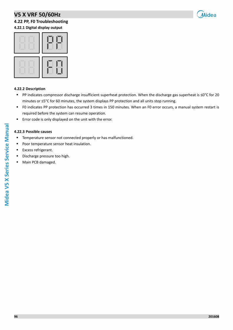
V5 X VRF 50/60Hz
96 201608
Mid
ea
V5
X S
eri
es
Serv
ice
Man
ual
4.22 PP, F0 Troubleshooting
Digital display output 4.22.1
Description 4.22.2
PP indicates compressor discharge insufficient superheat protection. When the discharge gas superheat is ≤0°C for 20
minutes or ≤5°C for 60 minutes, the system displays PP protection and all units stop running.
F0 indicates PP protection has occurred 3 times in 150 minutes. When an F0 error occurs, a manual system restart is
required before the system can resume operation.
Error code is only displayed on the unit with the error.
Possible causes 4.22.3
Temperature sensor not connected properly or has malfunctioned.
Poor temperature sensor heat insulation.
Excess refrigerant.
Discharge pressure too high.
Main PCB damaged.
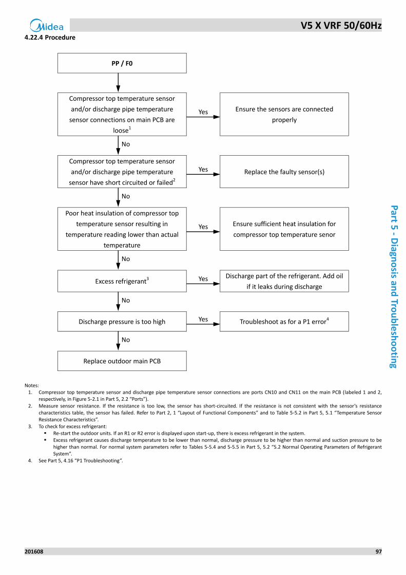
V5 X VRF 50/60Hz
201608 97
Part 5
- Diagn
osis an
d Tro
ub
lesh
oo
ting
Procedure 4.22.4
PP / F0
Compressor top temperature sensor
and/or discharge pipe temperature
sensor connections on main PCB are
loose1
Yes Ensure the sensors are connected
properly
No
Compressor top temperature sensor
and/or discharge pipe temperature
sensor have short circuited or failed2
Yes Replace the faulty sensor(s)
No
Poor heat insulation of compressor top
temperature sensor resulting in
temperature reading lower than actual
temperature
Yes Ensure sufficient heat insulation for
compressor top temperature senor
No
Excess refrigerant3 Yes Discharge part of the refrigerant. Add oil
if it leaks during discharge
No
Discharge pressure is too high Yes Troubleshoot as for a P1 error4
No
Replace outdoor main PCB
Notes:
1. Compressor top temperature sensor and discharge pipe temperature sensor connections are ports CN10 and CN11 on the main PCB (labeled 1 and 2, respectively, in Figure 5-2.1 in Part 5, 2.2 “Ports”).
2. Measure sensor resistance. If the resistance is too low, the sensor has short-circuited. If the resistance is not consistent with the sensor’s resistance characteristics table, the sensor has failed. Refer to Part 2, 1 “Layout of Functional Components” and to Table 5-5.2 in Part 5, 5.1 “Temperature Sensor Resistance Characteristics”.
3. To check for excess refrigerant: Re-start the outdoor units. If an R1 or R2 error is displayed upon start-up, there is excess refrigerant in the system. Excess refrigerant causes discharge temperature to be lower than normal, discharge pressure to be higher than normal and suction pressure to be
higher than normal. For normal system parameters refer to Tables 5-5.4 and 5-5.5 in Part 5, 5.2 “5.2 Normal Operating Parameters of Refrigerant System”.
4. See Part 5, 4.16 “P1 Troubleshooting”.
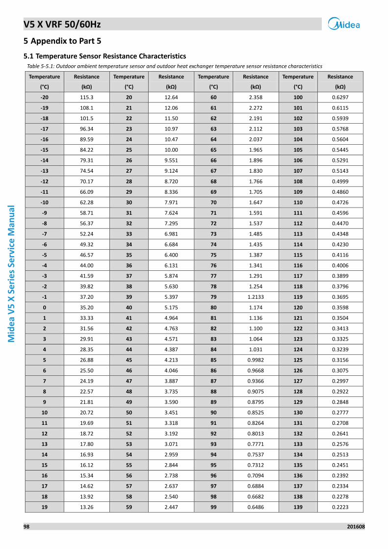
V5 X VRF 50/60Hz
98 201608
Mid
ea
V5
X S
eri
es
Serv
ice
Man
ual
5 Appendix to Part 5
5.1 Temperature Sensor Resistance Characteristics Table 5-5.1: Outdoor ambient temperature sensor and outdoor heat exchanger temperature sensor resistance characteristics
Temperature
(°C)
Resistance
(kΩ)
Temperature
(°C)
Resistance
(kΩ)
Temperature
(°C)
Resistance
(kΩ)
Temperature
(°C)
Resistance
(kΩ)
-20 115.3 20 12.64 60 2.358 100 0.6297
-19 108.1 21 12.06 61 2.272 101 0.6115
-18 101.5 22 11.50 62 2.191 102 0.5939
-17 96.34 23 10.97 63 2.112 103 0.5768
-16 89.59 24 10.47 64 2.037 104 0.5604
-15 84.22 25 10.00 65 1.965 105 0.5445
-14 79.31 26 9.551 66 1.896 106 0.5291
-13 74.54 27 9.124 67 1.830 107 0.5143
-12 70.17 28 8.720 68 1.766 108 0.4999
-11 66.09 29 8.336 69 1.705 109 0.4860
-10 62.28 30 7.971 70 1.647 110 0.4726
-9 58.71 31 7.624 71 1.591 111 0.4596
-8 56.37 32 7.295 72 1.537 112 0.4470
-7 52.24 33 6.981 73 1.485 113 0.4348
-6 49.32 34 6.684 74 1.435 114 0.4230
-5 46.57 35 6.400 75 1.387 115 0.4116
-4 44.00 36 6.131 76 1.341 116 0.4006
-3 41.59 37 5.874 77 1.291 117 0.3899
-2 39.82 38 5.630 78 1.254 118 0.3796
-1 37.20 39 5.397 79 1.2133 119 0.3695
0 35.20 40 5.175 80 1.174 120 0.3598
1 33.33 41 4.964 81 1.136 121 0.3504
2 31.56 42 4.763 82 1.100 122 0.3413
3 29.91 43 4.571 83 1.064 123 0.3325
4 28.35 44 4.387 84 1.031 124 0.3239
5 26.88 45 4.213 85 0.9982 125 0.3156
6 25.50 46 4.046 86 0.9668 126 0.3075
7 24.19 47 3.887 87 0.9366 127 0.2997
8 22.57 48 3.735 88 0.9075 128 0.2922
9 21.81 49 3.590 89 0.8795 129 0.2848
10 20.72 50 3.451 90 0.8525 130 0.2777
11 19.69 51 3.318 91 0.8264 131 0.2708
12 18.72 52 3.192 92 0.8013 132 0.2641
13 17.80 53 3.071 93 0.7771 133 0.2576
14 16.93 54 2.959 94 0.7537 134 0.2513
15 16.12 55 2.844 95 0.7312 135 0.2451
16 15.34 56 2.738 96 0.7094 136 0.2392
17 14.62 57 2.637 97 0.6884 137 0.2334
18 13.92 58 2.540 98 0.6682 138 0.2278
19 13.26 59 2.447 99 0.6486 139 0.2223
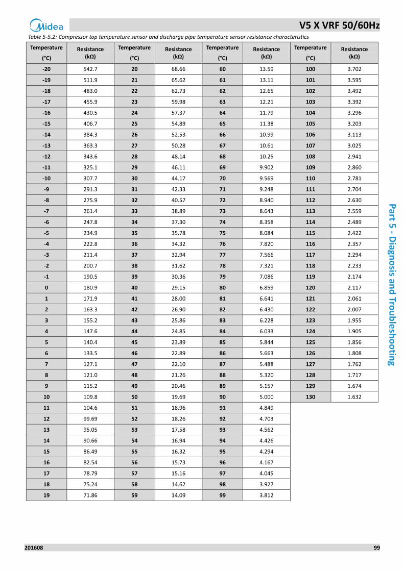
V5 X VRF 50/60Hz
201608 99
Part 5
- Diagn
osis an
d Tro
ub
lesh
oo
ting
Table 5-5.2: Compressor top temperature sensor and discharge pipe temperature sensor resistance characteristics
Temperature
(°C)
Resistance (kΩ)
Temperature
(°C)
Resistance (kΩ)
Temperature
(°C)
Resistance (kΩ)
Temperature
(°C)
Resistance (kΩ)
-20 542.7 20 68.66 60 13.59 100 3.702
-19 511.9 21 65.62 61 13.11 101 3.595
-18 483.0 22 62.73 62 12.65 102 3.492
-17 455.9 23 59.98 63 12.21 103 3.392
-16 430.5 24 57.37 64 11.79 104 3.296
-15 406.7 25 54.89 65 11.38 105 3.203
-14 384.3 26 52.53 66 10.99 106 3.113
-13 363.3 27 50.28 67 10.61 107 3.025
-12 343.6 28 48.14 68 10.25 108 2.941
-11 325.1 29 46.11 69 9.902 109 2.860
-10 307.7 30 44.17 70 9.569 110 2.781
-9 291.3 31 42.33 71 9.248 111 2.704
-8 275.9 32 40.57 72 8.940 112 2.630
-7 261.4 33 38.89 73 8.643 113 2.559
-6 247.8 34 37.30 74 8.358 114 2.489
-5 234.9 35 35.78 75 8.084 115 2.422
-4 222.8 36 34.32 76 7.820 116 2.357
-3 211.4 37 32.94 77 7.566 117 2.294
-2 200.7 38 31.62 78 7.321 118 2.233
-1 190.5 39 30.36 79 7.086 119 2.174
0 180.9 40 29.15 80 6.859 120 2.117
1 171.9 41 28.00 81 6.641 121 2.061
2 163.3 42 26.90 82 6.430 122 2.007
3 155.2 43 25.86 83 6.228 123 1.955
4 147.6 44 24.85 84 6.033 124 1.905
5 140.4 45 23.89 85 5.844 125 1.856
6 133.5 46 22.89 86 5.663 126 1.808
7 127.1 47 22.10 87 5.488 127 1.762
8 121.0 48 21.26 88 5.320 128 1.717
9 115.2 49 20.46 89 5.157 129 1.674
10 109.8 50 19.69 90 5.000 130 1.632
11 104.6 51 18.96 91 4.849
12 99.69 52 18.26 92 4.703
13 95.05 53 17.58 93 4.562
14 90.66 54 16.94 94 4.426
15 86.49 55 16.32 95 4.294
16 82.54 56 15.73 96 4.167
17 78.79 57 15.16 97 4.045
18 75.24 58 14.62 98 3.927
19 71.86 59 14.09 99 3.812
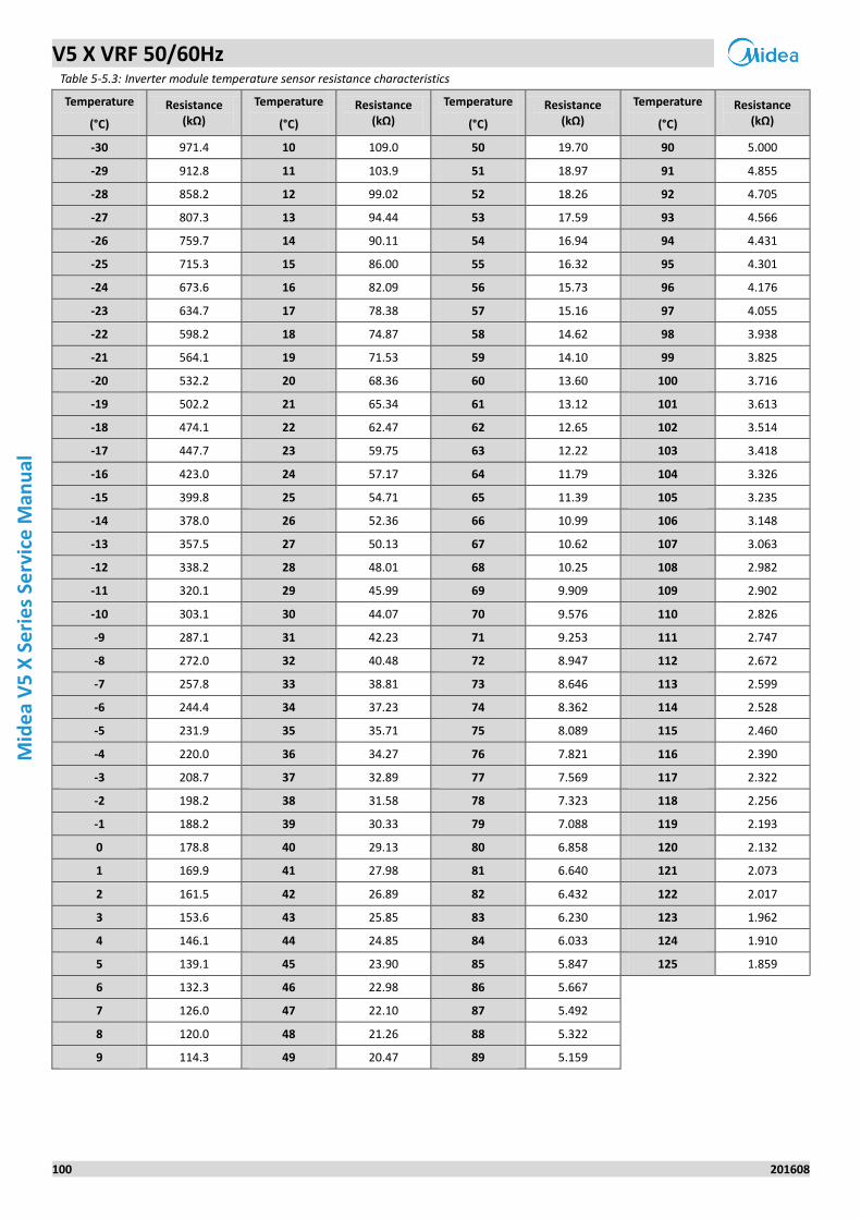
V5 X VRF 50/60Hz
100 201608
Mid
ea
V5
X S
eri
es
Serv
ice
Man
ual
Table 5-5.3: Inverter module temperature sensor resistance characteristics
Temperature
(°C)
Resistance (kΩ)
Temperature
(°C)
Resistance (kΩ)
Temperature
(°C)
Resistance (kΩ)
Temperature
(°C)
Resistance (kΩ)
-30 971.4 10 109.0 50 19.70 90 5.000
-29 912.8 11 103.9 51 18.97 91 4.855
-28 858.2 12 99.02 52 18.26 92 4.705
-27 807.3 13 94.44 53 17.59 93 4.566
-26 759.7 14 90.11 54 16.94 94 4.431
-25 715.3 15 86.00 55 16.32 95 4.301
-24 673.6 16 82.09 56 15.73 96 4.176
-23 634.7 17 78.38 57 15.16 97 4.055
-22 598.2 18 74.87 58 14.62 98 3.938
-21 564.1 19 71.53 59 14.10 99 3.825
-20 532.2 20 68.36 60 13.60 100 3.716
-19 502.2 21 65.34 61 13.12 101 3.613
-18 474.1 22 62.47 62 12.65 102 3.514
-17 447.7 23 59.75 63 12.22 103 3.418
-16 423.0 24 57.17 64 11.79 104 3.326
-15 399.8 25 54.71 65 11.39 105 3.235
-14 378.0 26 52.36 66 10.99 106 3.148
-13 357.5 27 50.13 67 10.62 107 3.063
-12 338.2 28 48.01 68 10.25 108 2.982
-11 320.1 29 45.99 69 9.909 109 2.902
-10 303.1 30 44.07 70 9.576 110 2.826
-9 287.1 31 42.23 71 9.253 111 2.747
-8 272.0 32 40.48 72 8.947 112 2.672
-7 257.8 33 38.81 73 8.646 113 2.599
-6 244.4 34 37.23 74 8.362 114 2.528
-5 231.9 35 35.71 75 8.089 115 2.460
-4 220.0 36 34.27 76 7.821 116 2.390
-3 208.7 37 32.89 77 7.569 117 2.322
-2 198.2 38 31.58 78 7.323 118 2.256
-1 188.2 39 30.33 79 7.088 119 2.193
0 178.8 40 29.13 80 6.858 120 2.132
1 169.9 41 27.98 81 6.640 121 2.073
2 161.5 42 26.89 82 6.432 122 2.017
3 153.6 43 25.85 83 6.230 123 1.962
4 146.1 44 24.85 84 6.033 124 1.910
5 139.1 45 23.90 85 5.847 125 1.859
6 132.3 46 22.98 86 5.667
7 126.0 47 22.10 87 5.492
8 120.0 48 21.26 88 5.322
9 114.3 49 20.47 89 5.159
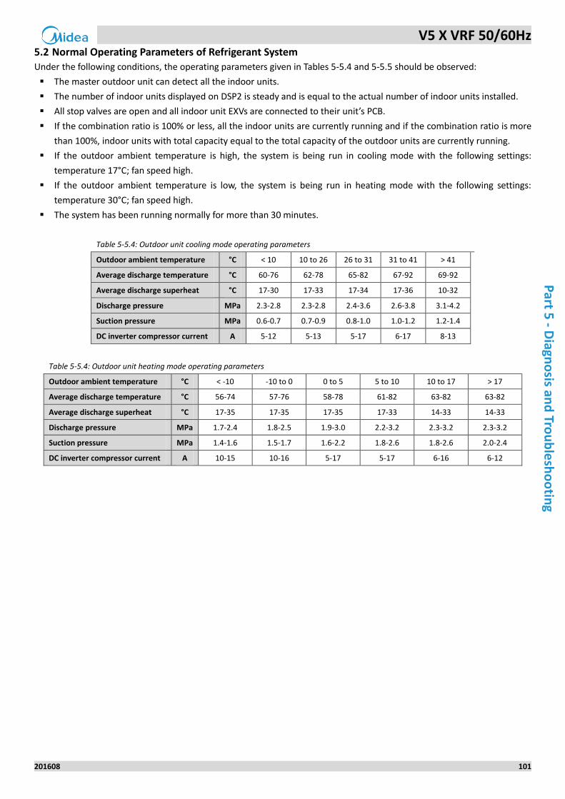
V5 X VRF 50/60Hz
201608 101
Part 5
- Diagn
osis an
d Tro
ub
lesh
oo
ting
5.2 Normal Operating Parameters of Refrigerant System
Under the following conditions, the operating parameters given in Tables 5-5.4 and 5-5.5 should be observed:
The master outdoor unit can detect all the indoor units.
The number of indoor units displayed on DSP2 is steady and is equal to the actual number of indoor units installed.
All stop valves are open and all indoor unit EXVs are connected to their unit’s PCB.
If the combination ratio is 100% or less, all the indoor units are currently running and if the combination ratio is more
than 100%, indoor units with total capacity equal to the total capacity of the outdoor units are currently running.
If the outdoor ambient temperature is high, the system is being run in cooling mode with the following settings:
temperature 17°C; fan speed high.
If the outdoor ambient temperature is low, the system is being run in heating mode with the following settings:
temperature 30°C; fan speed high.
The system has been running normally for more than 30 minutes.
Table 5-5.4: Outdoor unit cooling mode operating parameters
Outdoor ambient temperature °C < 10 10 to 26 26 to 31 31 to 41 > 41
Average discharge temperature °C 60-76 62-78 65-82 67-92 69-92
Average discharge superheat °C 17-30 17-33 17-34 17-36 10-32
Discharge pressure MPa 2.3-2.8 2.3-2.8 2.4-3.6 2.6-3.8 3.1-4.2
Suction pressure MPa 0.6-0.7 0.7-0.9 0.8-1.0 1.0-1.2 1.2-1.4
DC inverter compressor current A 5-12 5-13 5-17 6-17 8-13
Table 5-5.4: Outdoor unit heating mode operating parameters
Outdoor ambient temperature °C < -10 -10 to 0 0 to 5 5 to 10 10 to 17 > 17
Average discharge temperature °C 56-74 57-76 58-78 61-82 63-82 63-82
Average discharge superheat °C 17-35 17-35 17-35 17-33 14-33 14-33
Discharge pressure MPa 1.7-2.4 1.8-2.5 1.9-3.0 2.2-3.2 2.3-3.2 2.3-3.2
Suction pressure MPa 1.4-1.6 1.5-1.7 1.6-2.2 1.8-2.6 1.8-2.6 2.0-2.4
DC inverter compressor current A 10-15 10-16 5-17 5-17 6-16 6-12
iOS Version Android Version
Midea CAC After-service Application
iOS Version
Midea CAC News Application
Add.: Midea Headquarters Building, 6 Midea Avenue, Shunde, Foshan, Guangdong, China
Postal code: 528311
Tel: +86-757-26338346 Fax: +86-757-22390205
cac.midea.com global.midea.com
Note: Product speci�cations change from time to time as product improvements and
developments are released and may vary from those in this document.
Commercial Air Conditioner Division
Midea Group