Embed Size (px)
Citation preview

Midlands State University
Faculty of Science and Technology
Department of Applied Physics and Telecommunications
GSM based Transformer Protection Monitoring and Control
BY
LUCKMORE MUTEMARINGA
R147224T
November 2016
DECLARATION
I, LUCKMORE MUTEMARINGA declare that I am the author of this dissertation and l
authorize the Midlands state University to lend this document to other institutions and
students for supporting scholarly research
SIGNATURE …………………………………………………………………
DATE
………………………………………………………………….

R14724T GSM BASED TRANSFORMER PROTECTION MONITORING AND CONTROL
1
Table of Contents CHAPTER 1 ................................................................................................................................................................... 3
1.1 Background to the study......................................................................................................................................... 3
1.2 Problem statement ................................................................................................................................................ 3
1.3 Aim ........................................................................................................................................................................ 4
1.4 Objectives .............................................................................................................................................................. 4
1.5 Justification ............................................................................................................................................................ 5
1.6 Scope ..................................................................................................................................................................... 5
1.7 System Design ........................................................................................................................................................ 5
1.8 Expected results ..................................................................................................................................................... 5
CHAPTER 2 ................................................................................................................................................................... 6
2.0 THEORETICAL ASPECTS ........................................................................................................................................... 6
2.1.1 TRANSFORMER PROTECTION ............................................................................................................................... 6
2.1.2 Current Transformer............................................................................................................................................ 7
2.1.3 Voltage Transformer............................................................................................................................................ 8
2.1.4Overcurrent Protection ........................................................................................................................................ 9
2.1.5Restricted Earth Fault Protection .......................................................................................................................... 9
2.1.6Differential Protection Scheme (DIFF) ..................................................................................................................10
2.1.7Buchholz protection ............................................................................................................................................11
2.1.8Overload Protection ............................................................................................................................................12
2.1.9 Basics of Transformers Thermal Performance .....................................................................................................13
2.3.0 Hardware ...........................................................................................................................................................15
2.3.1 Switch ................................................................................................................................................................15
2.3.2 Relays .................................................................................................................................................................15
2.3.3 Arduino/Genuino Uno ........................................................................................................................................17
2.3.4 SIM900 GSM Module ..........................................................................................................................................21
2.3.5 MQ2 gas sensor ..................................................................................................................................................23
Reference ...................................................................................................................................................................24
CHAPTER 3 ..................................................................................................................................................................25
3.0 INTRODUCTION TO PROJECT RESEARCH METHODS ...............................................................................................26
3.1 DEVELOPMENT ......................................................................................................................................................26
3.1.2 Eagle Software ...................................................................................................................................................27
R14724T GSM BASED TRANSFORMER PROTECTION MONITORING AND CONTROL
2
3.1.3 PCB Circuit Board fabrication ..............................................................................................................................27
3.1.4 Printing artwork .................................................................................................................................................27
3.1.5 Exposure ............................................................................................................................................................27
3.1.6 Developing .........................................................................................................................................................27
3.1.7 Etching ...............................................................................................................................................................28
3.1.8 Cutting and drilling .............................................................................................................................................28
3.1.9 Circuit maker ......................................................................................................................................................28
3.2 Breadboard ...........................................................................................................................................................28
3.2.1 Soldering ............................................................................................................................................................29
3.2.2 Arduino ..............................................................................................................................................................29
3.2.3 Coding ................................................................................................................................................................29
3.2.4 Assembling .........................................................................................................................................................29
3.2.5. Debugging .........................................................................................................................................................29
3.2.6 Programming......................................................................................................................................................30
3.3 HOW THE PROJECT WORKS ...................................................................................................................................30
References ..................................................................................................................................................................33
FINDINGS, RESULTS AND ANALYSIS .............................................................................................................................35
4.0 FINDINGS ..............................................................................................................................................................35
4.1 RESULTS ................................................................................................................................................................36
4.2 LIMITATIONS .........................................................................................................................................................44
CHAPTER 5 ..................................................................................................................................................................45
5.0 CONCLUSION .........................................................................................................................................................45
5.1 RECOMMENDATIONS ............................................................................................................................................45

R14724T GSM BASED TRANSFORMER PROTECTION MONITORING AND CONTROL
3
CHAPTER 1
1.1 Background to the study High voltage power transformers can last a long time if care is taken to prevent them operating above their
ratings. It therefore becomes necessary to monitor the operating conditions and performance of these
transformers in order to avoid or reduce disruption due to sudden and unexpected failure. The reliability of
power distribution systems can be increased by using monitoring systems for transformers not only for high
voltage power transformers but also for low voltage power transformers. A great number of power companies
utilize the SCADA system for online monitoring of high voltage primary power transformers but extending the
SCADA technologies for real time monitoring of distribution power transformers is quite a huge cost.
Therefore, we need to develop a cost effective system that monitors the key parameters whose variations affect
the distribution system. Loading transformers above their rated capacities and power cooling systems of
transformers are the two major causes of transformer failure in distribution transformers. Real time monitoring
of these key parameters is necessary for evaluating the performance of the distribution transformer and also
helpful to avoid or reduce outages and consequent loss of revenue to the power Authority (ZETDC).
GSM substation monitoring and control system is a system that can be used to control substation equipment
such as transformer tap changers and high voltage circuit breakers. It can also be used to monitor transformer
temperature, oil level and voltage, circuit breaker and isolator status and tap changer status. In fact everything in
a substation that can have a sensor fitted on it can be monitored by this system. The microcontroller facilitates
the communication between user and device. The GSM module is used to allow this user-device communication
to be done cordlessly and remotely. The Arduino 1.6.9 software is used to specify how the control and
monitoring of devices will be done i.e. how to deal with sensor.
1.2 Problem statement
When a 33kv transformer circuit breaker at a remote distribution substation trips due to an overload condition, a
technician and at least an assistant may have to drive quite a long distance to the substation to reduce load by
switching off other feeder circuit breakers then reset and close the 33kv circuit breaker. An overload condition
is not necessarily a permanent fault, it is in fact a temporary condition that can easily be rectified before an
R14724T GSM BASED TRANSFORMER PROTECTION MONITORING AND CONTROL
4
outage taking out the transformer occurs. This makes it very expensive to repair a transient fault. A long
distance of many kilometers is travelled resulting into a huge cost being incurred. Bigger substations are
controlled and monitored by the National Control Centre using high voltage power line carrier system (PLC) for
communication, but the smaller and remote substations suffer. Since the smaller substations are dotted
throughout the country it becomes unreasonably expensive to connect all of them to the PLC network. This
project then seeks to eradicate the problem by introducing a reasonably priced system to reduce costs of outage
to the electricity supply network and at the same time monitor the network from remote so that an operative can
make decisions on system management without having to travel to a remote place, unless it is really necessary
to do so.
1.3 Aim The major purpose of this project is to come up with a design of a wireless monitoring system and implement it
on distribution transformers. Data will be collected through various sensors that measure temperature and oil
level, and the system will make use of overcurrent relay, oil temperature relay bucholz gas relay already
installed on transformers for status indications of the status of temperature and oil level indications. A central
microcontroller will be used to collect all the data from the sensors/relays and send it to a user using a GSM
module.
1.4 Objectives Main objectives:
To design an embedded system that monitors temperature of transformers and automatically takes out
part of the load from transformer when it‟s overloaded.
To develop a cost effective system to complement existing transformer overload protection.
To provide timeous notification of transformer outages to control personnel.
Allow remote operation of circuit breakers associated with transformers and feeders.

R14724T GSM BASED TRANSFORMER PROTECTION MONITORING AND CONTROL
5
1.5 Justification
The wireless transformer monitoring system will result in lower costs to the power company and an
increase in customer satisfaction due to quicker resolution of transformer overload faults.
The system will allow remote operation of circuit breaker to ensure safety of operating personnel.
1.6 Scope
The immediate scope of this project is to monitor the transformer winding temperature and control
circuit breakers associated with the transformers in remote places.
The area of use is generally in substations which are not covered by the SCADA system.
This project implements the concept of wireless communication to enable data acquisition at a remote
site.
1.7 System Design
An Arduino Uno microcontroller is interfaced with a couple of sensors and relays and a GSM module to enable
remote monitoring and control.
1.8 Expected results
SMS alert of fault outage at a remote substation site.
Circuit breaker outage initiated from SMS.
Outage initiated from sensors.

R14724T GSM BASED TRANSFORMER PROTECTION MONITORING AND CONTROL
6
CHAPTER 2
2.0 THEORETICAL ASPECTS
The factors that are considered on a transformer protection scheme depend on the application size and
importance of the transformer concerned. In order to mitigate against the harmful effects of thermal stress and
fault induced electrodynamic forces, it is advisable to ensure that the protection scheme employed keeps to the
minimum possible, the disconnection time in the event of a fault occurring within the transformer. Small
distribution transformers can be protected satisfactorily, from both technical and economic considerations, by
the use of fuses or overcurrent relays. This results in time-delayed protection in order to satisfy the need for
downstream co-ordination requirements. Time delayed fault clearance is however unacceptable on larger power
transformers used in distribution, transmission and generator applications, due to system operation/stability and
cost of repair/length of outage considerations.
2.1.1 TRANSFORMER PROTECTION The challenges associated with transformers require efficient means of protection. With the advent of static
relays it is now the norm for a modern relay to be designed to provide all of the required protection elements in
a single package, whilst in electromechanical relay types that would require several different relays each with
its own connections to perform a unique function. This created a problem of larger overall CT burdens. See Fig
2.1 .The advantage of static relays is their speed of operation, portability, accuracy, less burden on the CTs and
great flexibility in terms of being programmable.
Below is a diagram fig 2.1 showing the basic protection set-up, including the elements involved in the
protection of power systems equipment which are current transformers (CTs), voltage transformers (VTs), relay

R14724T GSM BASED TRANSFORMER PROTECTION MONITORING AND CONTROL
7
and circuit breaker.
Fig 2.1 Basic protection setup
2.1.2 Current Transformer
A current transformer is a device used to reduce the magnitude of fault current in the primary circuit to values
which can be managed by the protection relays [1]. It provides an interface of the primary circuit and the control
circuit. It should be able to insulate the control circuit from the high voltages of the primary circuit. Protection
CT have low saturation points in order to protect the relays for excessive currents. Protection CTs are usually
required to operate above full load currents of system but under these conditions it‟s no longer accuracy that is
critical but the ability to be able to handle high magnetising currents on switching on of highly inductive loads
but at the same time able to distinguish inrush currents from fault currents. Current transformers secondary are
not to be open circuited when the primary current in which they are connected is carrying load.

R14724T GSM BASED TRANSFORMER PROTECTION MONITORING AND CONTROL
8
2.1.3 Voltage Transformer
Electromagnetic VTs
A voltage transformer is essentially similar in most respects to a power transformer [9]. The only notable
difference being that it has lower power rating. It is thus rated in VA while the larger power transformer is rated
in at least KVA .Their purpose is to reduce the high voltage of the primary system to smaller values of voltage,
the standard output being 110V which relays can easily handle without the need of the very high voltage
required for the primary circuit. They are used to transform voltage of up to 36KV to 110V.Above 36KV it
doesn‟t make economic sense to use them. At above 36KV it becomes necessary to use Capacitor Voltage
Transformers as they become the cheaper option. Voltage transformer secondary circuits are not supposed to be
shorted out when their primary circuit are connected as this results in very high currents flowing resulting in
them overheating. This is in contrast to current transformers which are not supposed to have their secondary
circuits open circuited on load.
Capacitor VTs
Capacitor voltage transformers (CVTs) employ a series string of high voltage capacitors to provide a voltage
divider network. They are used in systems with voltages higher than 36KV. A suitable voltage is tapped off the
voltage divider network. This voltage is then supplied to a voltage transformer which then gives the standard
output of 110V which can then be used to supply relays requiring them. They are also used in the tuning circuit
of wave traps used in power line carrier systems. The results in the use of technologies such as teleprotection.
Fig 2.2 Protection Relay

R14724T GSM BASED TRANSFORMER PROTECTION MONITORING AND CONTROL
9
In order to effect control of circuit breakers relays are employed .Different kinds of relays are designed to
measure specific elements of the power systems .Some relays respond to current, others measure impedance
whilst other respond to changes in frequency or voltages. They normally have normally open contacts and
normally closed contacts. When a certain pre-set value is reached relay will operated and close its normally
open contacts whilst at the same time opening their normally closed contacts. The normally open contacts are
then used to supply specified power to closing coils of circuit breakers to close them or to trip coils of circuit
breakers in order to open them. The protection relay is expected to be very fast in terms of speed of operation in
order to ensure that faults are not sustained on the power system equipment. They are also expected to be
sensitive and selective so that they can pick up small changes in the power system elements.
Relays have what are called targets, these are basically a means of displaying to the operator whether a relay has
operated or not.
2.1.4Overcurrent Protection
Overcurrent protection is mainly concern with protecting equipment from the effects of very high current which
flow in the event of a short circuit occurring in a circuit. They are basically current operated devices.
Overcurrent protection is not unit protection so intentional time delays can be introduced in order to allow
coordination with downstream devices. These relays can self-resetting in that they revert to their original state
once the overcurrent condition is removed from the power system. Only the target would need manual resetting.
2.1.5Restricted Earth Fault Protection
REF is used to provide unit protection of earth fault on transformer windings[1]. The winding to be protected is
placed within boundaries marked by CTs. Three CTs are installed in the three phases of the power supply and
their sum output is fed to a CT connected to the Neutral point of the star transformer winding to be protected.

R14724T GSM BASED TRANSFORMER PROTECTION MONITORING AND CONTROL
10
REF is a form of unit protection. See fig 2.1 below.
Fig 2.3 Restricted Earth Fault Scheme
2.1.6Differential Protection Scheme (DIFF)
This is unit protection which makes use of comparisons of currents from the HV lines and the LV by connecting
a set of CT‟s at the HV phases with the corresponding ones at the LV side and having differential relays across
these currents, this creates a balanced circulation in the phase CT‟s, thus at normal operation no currents flow
into the differential relay, a fault in the zone defined by the line CT‟s disturbs this equilibrium permitting a
differential current to pass through the differential relay which then operates.
Principles of High and Low Impedance differential schemes
A relay or a relay circuit whose voltage setting is not less than the calculated maximum voltage which can
appear across its terminals under the assigned maximum through fault conditions( relay impedance is higher
than the impedance of the secondary circuit of a saturated CT is referred to as a high impedance relay. It can be
applied in the following situations;
Protection co-ordination is difficult / impossible using time delayed elements
Fast fault clearance is critical
It can be used on all items of plant in one form or another to form a defined zone of protection dictated by CT
location.

R14724T GSM BASED TRANSFORMER PROTECTION MONITORING AND CONTROL
11
Low impedance relay has impedance which is less than the total impedance of the secondary circuit of current
transformer which is in saturation and the voltage setting in less than the calculated maximum voltage which
appears at its terminals. Where relay impedance alone is too low to ensure stability then the relay circuit
impedance can be increased through the addition of an external resistor connected in series with the relay.
Figure 2.4 below depicts the principle. Current transformers placed on the primary and those on the secondary
sides are connected to form a circulating current system.
Fig 2.4 Differential Protection Scheme
2.1.7Buchholz protection
Buchholz protection can only be applied on all transformers fitted with a conservator tank [1]. The Buchholz
relay is itself contained in a housing which is connected in the middle of the pipe to the conservator .All faults
that occur on device immersed in oil will cause heating of the oil which result in the decomposing of the to
release methane and other gases. The percentage composition of the gases can then be used to determine the
nature of fault. For example damage to paper insulation of a transformer winding will give different gas ratios
as compared to direct oil decomposition. A developing fault e.g. loose connection will release gas slowly whilst
a heavy fault will release the gas very rapidly in the form of a surge.

R14724T GSM BASED TRANSFORMER PROTECTION MONITORING AND CONTROL
12
Fig 2.5 Bulcholz Relay
Buchholz: this is a relay connected between conservator and main tank or at the top most point in the OLTC
tank. It has contacts which make when the oil equilibrium is disturbed in the tank; the protection appears in two
forms. Buchholz gas, this initiates an alarm when gas collects in the buchholz chamber after being generated
from oil or insulation breakdown from winding faults or gas which would have been trapped in the tank during
filling. These gases pile up in the chamber and produce a lowering of oil level which affects float switches that
subsequently closes contacts signaling an alarm. Buchholz Surge causes a trip; this would have been generated
from a more severe fault like arcing which then causes violent oil movements which affect higher float switches
in the chamber thus making the trip contacts. The gas in the buchholz chamber is collected and analyzed and
various interpretations come from the relative proportions of the gases hydrogen, acetylene, nitrogen, Carbon
Monoxide, Carbon Dioxide, methane, Oxygen.
Hydrogen with < 2% Carbon Monoxide
means fault involves only insulating
oil.
Hydrogen with >20% Carbon
Monoxide means fault involves oil and
solid insulation.
2.1.8Overload Protection Windings of power transformers must never be allowed to overheat as this leads to significant reduction in the
lifespan of the transformers. A maximum temperature rise of 95°C is normally accepted to be the normal value

R14724T GSM BASED TRANSFORMER PROTECTION MONITORING AND CONTROL
13
pf temperature beyond which insulation of transformers will rapidly deteriorate. Winding temperature is
normally used as the basis for transformer overload protection. A true representation of the load current is
represented as a temperature through the use of thermal imaging. Thermal imaging involves connecting a CT on
the winding whose temperature is to be measured and then connect the secondary of this CT to a heater to heat
up oil on a pouch on the transformer. A temperature sensor or thermometer is then used to determine the
winding temperature. A protection relay or tilt mercury switches are then used to trip appropriate circuit
breakers.
2.1.9 Basics of Transformers Thermal Performance Winding temperature trip, Oil temperature trip (WTT, OTT) are temperature caused trips from thermometers
and CTs which measure the temperature of the oil and winding respectively. The trip will be initiated when
certain temperatures are reached and these are generally set to be 115oC and 95
oC respectively, these
temperature increases are caused by mainly overloading the transformers, for prolonged times and they usually
trip the LV breaker if the grading is proper.
OLT (Oil Level Trip): Oil level trip is a measurement of the level in the main or OLTC tank, when it goes
below a certain level trip signals are sent as operating at lower oil levels is detrimental to the transformer, as
insulation will be lower and cooling would be compromised.

R14724T GSM BASED TRANSFORMER PROTECTION MONITORING AND CONTROL
14
Fig 2.6 Simple Transformer representation
Transformer rating is determined by basing on how much power the transformer can deliver continuously when
being operated at its rated voltage and frequency [3]. The transformer rating limit is determined by the thermal
capability of the materials used to construct the transformer namely the core materials, and insulating oil used
for coil. Load losses are the main contributors as the source of transformer heating current loss. Ambient
temperature measurement is used as a reference point to ensure that the transformer is protected regardless of
outside temperature condition.
The simplest method for cooling transformers is transferring heat from the core and windings to the insulating
oil. Natural circulation of the oil transfers the heat to external radiators [5]. The radiators provide an increased
the surface area for cooling of the transformer tank. Pumps may be used to increase the rate of flow of
transformer oil, thereby increasing the cooling efficiency of the radiators. In non-directed flow transformers, the
pumped oil flows freely through the tank. In directed flow transformers, the pumped oil is forced to flow
through the windings. Forced air cooling is also another technique commonly used to provide better cooling of
large transformers [6]. Fans are employed to blow air at high pressure onto the surface of the radiators, which
can double the efficiency of the radiators. For some large power transformers, water cooling may replace large
radiators. Large power transformers may also have additional ratings for multiple stages of forced cooling.

R14724T GSM BASED TRANSFORMER PROTECTION MONITORING AND CONTROL
15
Normally, only two stages are applied, providing transformer ratings equivalent to 133% and 167% of the self-
cooled rating.
Both the IEEE and the IEC established standard designations for the various cooling modes of transformers.
The IEEE has adopted the IEC designations. The designation completely describes the cooling method for the
transformer, and the cooling method impacts the response of the transformer insulating oil to overload
conditions.
Table 1 lists the common transformer cooling designations.
Table 1
2.3.0 Hardware
2.3.1 Switch
A switch is an electrical device that can open and close a circuit. A switch may be directly manipulated by a
human being as a control signal to a system, such as a computer keyboard switch or to control power flow in a
circuit. Automatic operated switches can be used to control circuits for example this 33kv circuit breaker.
2.3.2 Relays A relay is an electrically operated switch. Many relays use an electromagnet to operate a switching mechanism
but other operating principles are also used. Relay are used where it is necessary to control a circuit by a power
signal or where circuit must be controlled by one signal. The first relays were used in long distance telegraphic
circuit. In this project a relay that can handle high power was used to directly control an electric load. Relays

R14724T GSM BASED TRANSFORMER PROTECTION MONITORING AND CONTROL
16
with calibrated operating characteristics and sometimes multiple coils are used to protect electrical circuits from
overload and faults.
Fig 2.7 Electromechanical relays (1900s)
Fig 2.8 Static or electronic relays (1960s)
For protective relays to perform their function satisfactorily they should have the following qualities:

R14724T GSM BASED TRANSFORMER PROTECTION MONITORING AND CONTROL
17
1. selectivity- to detect only the faulty session
11. simplicity- to be easily maintained
111. speed- to respond to fault as quickly as possible
1 v. reliability- to work only under pre-determined conditions
In this 33kv Circuit Breaker control and monitoring project, a simple electromagnetic relay consisting of a coil
of wire wrapped around a soft iron core, an iron yoke which provides a low reluctance path for magnetic flux, a
movable iron armature and two sets of contacts.
When an electric current is passed through the coil it generates a magnetic field that activates the armature and
the consequent movement of the movable contacts either makes or breaks a connection with a fixed contact,
opening and closing the circuit.
2.3.3 Arduino/Genuino Uno Arduino/Genuino Uno is a microcontroller board based on the ATmega328P (datasheet). It has 14 digital
input/output pins (of which 6 can be used as PWM outputs), 6 analog inputs, a 16 MHz quartz crystal, a USB
connection, a power jack, an ICSP header and a reset button. It contains everything needed to support the
microcontroller; simply connect it to a computer with a USB cable or power it with an AC-to-DC adapter or
battery to get started. You can tinker with your UNO without worrying too much about doing something wrong,
worst case scenario you can replace the chip for a few dollars and start over again.
"Uno" means one in Italian and was chosen to mark the release of Arduino Software (IDE) 1.0. The Uno board
and version 1.0 of Arduino Software (IDE) were the reference versions of Arduino, now evolved to newer
releases. The Uno board is the first in a series of USB Arduino boards, and the reference model for the Arduino
platform; for an extensive list of current, past or outdated boards see the Arduino index of boards.
Technical specs

R14724T GSM BASED TRANSFORMER PROTECTION MONITORING AND CONTROL
18
Microcontroller ATmega328P
Operating Voltage 5V
Input Voltage (recommended) 7-12V
Input Voltage (limit) 6-20V
Digital I/O Pins 14 (of which 6 provide PWM output)
PWM Digital I/O Pins 6
Analog Input Pins 6
DC Current per I/O Pin 20 mA
DC Current for 3.3V Pin 50 mA
Flash Memory 32 KB (ATmega328P)
of which 0.5 KB used by bootloader
SRAM 2 KB (ATmega328P)
EEPROM 1 KB (ATmega328P)
Clock Speed 16 MHz
LED_BUILTIN 13
Length 68.6 mm
Width 53.4 mm
Weight
25 g
Programming

R14724T GSM BASED TRANSFORMER PROTECTION MONITORING AND CONTROL
19
The Arduino/Genuino Uno can be programmed with the (Arduino Software (IDE))[8]. Select
"Arduino/Genuino Uno from the Tools > Board menu (according to the microcontroller on your board). For
details, see the reference and tutorials.
The ATmega328 on the Arduino/Genuino Uno comes preprogrammed with a bootloader that allows you to
upload new code to it without the use of an external hardware programmer. It communicates using the original
STK500 protocol (reference, C header files)[8].
You can also bypass the bootloader and program the microcontroller through the ICSP (In-Circuit Serial
Programming) header using Arduino ISP or similar; see these instructions for details.
The ATmega16U2 (or 8U2 in the rev1 and rev2 boards) firmware source code is available in the Arduino
repository. The ATmega16U2/8U2 is loaded with a DFU bootloader, which can be activated by:
On Rev1 boards: connecting the solder jumper on the back of the board (near the map of Italy) and then
resetting the 8U2.
On Rev2 or later boards: there is a resistor that pulling the 8U2/16U2 HWB line to ground, making it
easier to put into DFU mode.
You can then use Atmel's FLIP software (Windows) or the DFU programmer (Mac OS X and Linux) to load a
new firmware. Or you can use the ISP header with an external programmer (overwriting the DFU bootloader).
See this user-contributed tutorial for more information.
The Arduino/Genuino Uno has a resettable polyfuse that protects your computer's USB ports from shorts and
overcurrent. Although most computers provide their own internal protection, the fuse provides an extra layer of
protection. If more than 500 mA is applied to the USB port, the fuse will automatically break the connection
until the short or overload is removed.
Differences with other boards
The Uno differs from all preceding boards in that it does not use the FTDI USB-to-serial driver chip. Instead, it
features the Atmega16U2 (Atmega8U2 up to version R2) programmed as a USB-to-serial converter.
Power
The Arduino/Genuino Uno board can be powered via the USB connection or with an external power supply.
The power source is selected automatically.
R14724T GSM BASED TRANSFORMER PROTECTION MONITORING AND CONTROL
20
External (non-USB) power can come either from an AC-to-DC adapter (wall-wart) or battery. The adapter can
be connected by plugging a 2.1mm center-positive plug into the board's power jack. Leads from a battery can be
inserted in the GND and Vin pin headers of the POWER connector.
The board can operate on an external supply from 6 to 20 volts. If supplied with less than 7V, however, the 5V
pin may supply less than five volts and the board may become unstable. If using more than 12V, the voltage
regulator may overheat and damage the board. The recommended range is 7 to 12 volts.
The power pins are as follows:
Vin. The input voltage to the Arduino/Genuino board when it's using an external power source (as
opposed to 5 volts from the USB connection or other regulated power source). You can supply voltage
through this pin, or, if supplying voltage via the power jack, access it through this pin.
5V.This pin outputs a regulated 5V from the regulator on the board. The board can be supplied with
power either from the DC power jack (7 - 12V), the USB connector (5V), or the VIN pin of the board
(7-12V). Supplying voltage via the 5V or 3.3V pins bypasses the regulator, and can damage your board.
It is not advised.
3V3. A 3.3 volt supply generated by the on-board regulator. Maximum current draw is 50 mA.
GND. Ground pins.
IOREF. This pin on the Arduino/Genuino board provides the voltage reference with which the
microcontroller operates. A properly configured shield can read the IOREF pin voltage and select the
appropriate power source or enable voltage translators on the outputs to work with the 5V or 3.3V.
Memory
The ATmega328 has 32 KB (with 0.5 KB occupied by the bootloader). It also has 2 KB of SRAM and 1 KB of
EEPROM (which can be read and written with the EEPROM library).

R14724T GSM BASED TRANSFORMER PROTECTION MONITORING AND CONTROL
21
2.3.4 SIM900 GSM Module The SIM900 is a complete Quad-band GSM/GPRS solution in a SMT module which can be embedded in the
customer applications. Featuring an industry-standard interface, the SIM900 delivers GSM/GPRS
850/900/1800/1900MHz performance for voice, SMS, Data, and Fax in a small form factor and with low power
consumption. With a tiny configuration of 24mm x 24mm x 3mm, SIM900 can fit almost all the space
requirements in any M2M application, especially for slim and compact demand of design.
SIM900 is designed with a very powerful single-chip processor integrating AMR926EJ-S core”Quad - band
GSM/GPRS module with a size of 24mmx24mmx3mm ”SMT type suit for customer application .
An embedded Powerful TCP/IP protocol stack based upon mature and field-proven platform, backed up by
support service, from definition to design and production

R14724T GSM BASED TRANSFORMER PROTECTION MONITORING AND CONTROL
22
Fig 2.9 GSM Module
General features
The GPRS Shield is based on SIM900 module from SIMCOM and compatible with Arduino and its clones. The
GPRS Shield provides you a way to communicate using the GSM cell phone network. The shield allows you to
achieve SMS, MMS, GPRS and Audio via UART by sending AT commands (GSM 07.07, 07.05 and SIMCOM
enhanced AT Commands). The shield also has the 12 GPIOs, 2 PWMs and an ADC of the SIM900 module
(They are all 2V8 logic) present onboard.

R14724T GSM BASED TRANSFORMER PROTECTION MONITORING AND CONTROL
23
Features:
Quad-Band 850 / 900/ 1800 / 1900 MHz - would work on GSM networks in all countries across the world.
GPRS multi-slot class 10/8
GPRS mobile station class B
Compliant to GSM phase 2/2+
Class 4 (2 W @ 850 / 900 MHz)
Class 1 (1 W @ 1800 / 1900MHz)
Control via AT commands - Standard Commands: GSM 07.07 & 07.05 | Enhanced Commands: SIMCOM AT
Commands.
Short Message Service - so that you can send small amounts of data over the network (ASCII or raw
hexadecimal).
Embedded TCP/UDP stack - allows you to upload data to a web server.
RTC supported.
Selectable serial port.
Speaker and Headphone jacks
Low power consumption - 1.5mA (sleep mode)
Industrial Temperature Range - -40°C to +85 °C
Size: 8.5x5.7x2cm (approx.)
2.3.5 MQ2 gas sensor MQ2 is basically a general purpose gas sensor (similar to MQ5) which can sense a broad range of gases like
LPG, Butane, Methane(CH4), Hydrogen and in addition to these gases MQ2 is sensitive to smoke as well.
The MQ series of gas sensors use a small heater inside with an electro-chemical sensor. They are sensitive for a
range of gasses and are used indoors at room temperature.
The output is an analog signal and can be read with an analog input of the Arduino. Since there are no electronic
components inside, most sensors can be used with AC and DC voltages.
The preferred wiring is to connect both 'A' pins together and both 'B' pins together. It is safer and it is assumed
that is has more reliable output results. Although many schematics and datasheets show otherwise, it are advised
to connect both 'A' pins together and connect both 'B' pins together.

R14724T GSM BASED TRANSFORMER PROTECTION MONITORING AND CONTROL
24
Fig 3.0 MQ2 Sensor
In the picture, the heater is for +5V and is connected to both 'A' pins. This is only possible if the heater needs a
fixed +5V voltage.
The variable resistor in the picture is the load-resistor and it can be used to determine a good value. A fixed
resistor for the load-resistor is used in most cases.
The Vout is connected to an analog input of the Arduino.
Reference
[1]Shephard, J. Morton, A.H. and Spence, L.F. Higher Electrical Engineering

R14724T GSM BASED TRANSFORMER PROTECTION MONITORING AND CONTROL
25
Mehta. Electrical power systems (Relays)
[2]Theraja, B.L. and Theraja, A.K. (1995). Electrical Technology, Delhi: Publication of Ram Naogar.
[3]H J. Pain Electromagnetic induction 3rd edition 1985
[4]Nagrath, I. J. Kothari, I. D. P. (2000). Power System Engineering, New Delhi: Tata, McGraw Hill
Publishing Company Limited.
[5]Richard C. Dorf, ed. (1993), The Electrical Engineering Handbook, Boca Raton: CRC Press, p. 1319, ISBN
0-8493-0185-8
[6]Edwin Bernard Kurtz, ed. (1997), The Lineman's and Cableman's Handbook (9th ed.), New York: McGraw
Hill, pp. 18–8 through 18–15, ISBN 0-07-036011-1
[7]B. M. Weedy (1972), Electric Power Systems (Second ed.), London: John Wiley and Sons, p. 26, ISBN 0-
471-92445-8
[8] https://www.arduino.cc/en/Guide/HomePage
CHAPTER 3 RESEARCH METHODS
R14724T GSM BASED TRANSFORMER PROTECTION MONITORING AND CONTROL
26
3.0 INTRODUCTION TO PROJECT RESEARCH METHODS Research methods may be explained as the systematic theoretical analysis of the methods applied to a project or
theoretical analysis of the body of methods and principles associated with a project.
I had an established collaboration with my organization, ZETDC Zimbabwe to have this project to develop a
GSM monitored and controlled 33kv Transformer Circuit Breaker at Lendy Park substation.
3.1 DEVELOPMENT The project success hinges on the ability to connect together the sections of the hardware depicted by the
diagrams, complemented by software which will run from the ATMega 328 Microcontroller. On the input side,
sensors, in this case a temperature sensor and gas sensor are connected to pin 9 &10 respectively. When pin 9
and/or pin 10 goes high appropriate actions are carried out by microcontroller and appropriate messages are sent
to mobile phone. This will be a “SIM900.println (Cb 1 Off)” command to the microcontroller which will in
turn send the sms to the GSM modem to be transmitted to the user mobile handset.
When a command is sent from a user mobile, to close the circuit breaker remotely, the signal is received by the
SIM900 GSM module as text. The microcontroller is so programmed as to constantly read the GSM module
until it sends characters as per written program. The microcontroller will then execute the program by making
the desired pin “HIGH” The pin is then connected to a relay to protect the microcontroller from excessive
current.
ATMega 328 has an inbuilt comparator. An analog 5V input is connected to the input analog pins. The program
is then set to respond to excessive voltage or under voltage in comparison to a set voltage limit. The following
software is to be used
Eagle for track layout
3.1.1 Multimeter
Before assembling, the populated Vero board has to be tested using a digital multi-meter to detect shorts caused
by soldering. Corrective action was taken in areas where the operation was not in line with what was expected.

R14724T GSM BASED TRANSFORMER PROTECTION MONITORING AND CONTROL
27
The multi-meter used was a Fluke 178 series. This is capable of measuring DC voltage up to 1000V. The
prototype operates with DC voltages of 5V, so the instrument was suitable for measuring input and output
voltages at each stage on the Vero board. Current measure was also in the correct range as it can measure
currents up to 20A.
3.1.2 Eagle Software Eagle software was used to generate circuit diagrams. It was used to draw the main circuit diagram. It has
myriad of components available for use with the advantage of being able to import any components in that
version.
3.1.3 PCB Circuit Board fabrication A printed circuit board or PCB is a board used to mechanically support and electrically connect electronic
components using conductive pathways, tracks or signal traces etched from copper sheets laminated onto a non-
conductive substrate.
3.1.4 Printing artwork The PCB layout was printed from onto a white piece of paper. The printing was then photocopied onto a
transparency paper. The transparency was used for photo-resist PCB board exposure in the next stage.
3.1.5 Exposure The first stage was the preparation of the PCB board for Exposure. The white/black protective film on the
resistive was torn off. The transparency artwork was placed on top of the PCB board and the artwork secured
with a masking tape. A small piece of glass material was then placed on the top to ensure a firm contact
between the artwork and the PCB board. Proximity was closely maintained to ensure that the trace was not
exposed to UV light. The PCB was then exposed to the UV light for 10 minutes using a normal fluorescent
lamp. The lamp was placed in close proximity to the artwork.
3.1.6 Developing Sodium hydroxide was used in developing the PCB. The solvent composite for making the developer consisted
of a ratio of 1-unit of sodium hydroxide to 20 units of water. A glass rod was used whilst working with the
material because glass is less reactive with most of chemical compounds. The PCB board by was immersed into
the chemical solution and was continuously agitated until the board was developed. The end point for the
development was the appearance of the color on PCB traces. The green layer is the photo resist layer which
protects the copper surface underneath during the etching process. The region to be etched away later was

R14724T GSM BASED TRANSFORMER PROTECTION MONITORING AND CONTROL
28
exposed and was brown in color. The brown color is the actual color of the copper because there is no photo-
resist coating to protect the surface. The developed PCB board was rinsed with running water after developing.
3.1.7 Etching Ferric chloride was used to etch away copper surface on the PCB board. A strong concentration of the ferric
chloride enables the etching process to be faster. The composition for the mixture of water to the acid was 3:1.
The speed of the chemical reaction between the etching solution and the PCB was increased by warming the
etching solution. The PCB was immersed into the solution and plastic gloves were used to handle for the
handling process. The PCB was agitated in the etching solution until the unwanted copper was removed. The
last stage was the removal of the photo-resist mask using sodium hydroxide. A stronger solution was used
because the etching was complete. The PCB board was rinsed with water and cleaned and dried.
3.1.8 Cutting and drilling The PCB holes were drilled using an electric drill. A 1mm drill bit was used for drilling process. The
dimensions of the board were marked out using a try square. After marking the required board size, the board
was then trimmed to the required board dimensions.
3.1.9 Circuit maker Simulation is the use of a computer program to test the behavior of a circuit. Simulation programs take
schematic as its input and then process to display the operation of the circuit in various ways. Computer
simulation of electronic circuits has been available for years, and has proven to be accurate and effective. This
can be done by such packages as Electronic Workbench, Circuit maker and others. In the design of various
modules of the system, Circuit maker was used to simulate the circuits. When designing circuits, it is always
advisable to test the circuits using computer simulation before proceeding with bread boarding. This is because
simulation is much faster than building them in a lab, and wiring mistakes are minimized. The software is safe
to use alone, and the components never breakdown. One can quickly determine if the circuit behaves as
planned. Uncertainties can be resolved immediately. However, simulation does not replace bread boarding.
3.2 Breadboard After simulation and establishing that the circuit was functional, the circuit was tested on a breadboard. A
breadboard provides a means for testing the circuit without wiring it permanently on a board. It is easy to
modify as the components are not soldered onto the board. It is good for simulation.

R14724T GSM BASED TRANSFORMER PROTECTION MONITORING AND CONTROL
29
3.2.1 Soldering All components were soldered onto the Vero board using a soldering gun and soldering wire. Population is
defined as the process of mounting components on the board. This is followed by soldering the components on
the board. This most common method is by means of soft solders in wire form. In populating the Vero board,
soft solders were used because they are readily available at low cost. They also offer an excellent combination
of electrical and mechanical properties. The first stage was heating the metal parts to be joined using a soldering
iron. Solder does not stick to unheated surfaces. Solder was the applied so that it melts to form a bond. After
making a soldered joint, a cutter was used each time to remove unnecessary extensions until the Vero was
completely populated.
3.2.2 Arduino The software program was written using Assembly Language Programming only.
3.2.3 Coding
Software development all begins with coding. The source code for a microcontroller can be written in assembly
language or in a high level language such as C. For this system, assembly language programming was used
because of the presence of the ATMega integrated development environment called Arduino. A typical
assembly language program will consist of some assembler directives, sub-routines if they are needed and the
main program code.
Assembler directives are a collection of commands that tell the assembler such things as the type of
microcontroller being used, its clock speed, etc. They also allow names to be used for memory locations, ports
and registers, so making the program more readable.
3.2.4 Assembling Alter writing the code, the program was assembled using an assembler in MPLAB. A task of the assembler is to
ensure that the program is written using the correct syntax (i.e. it conforms to the spelling and format required
by the assembler). A program can be syntactically correct but meaningless in the sense that it does not do
anything useful or achieve the desired effect. It could also still have what are called logical errors.
3.2.5. Debugging The next step was to execute the program and see if it did what was required, and if not, modify it so, that it
worked as required. This process is known as debugging. Debugging took up more time than the actual writing
of the original program source code. They are a number of ways in which a program can be debugged.
Debugging can be done through simulation.

R14724T GSM BASED TRANSFORMER PROTECTION MONITORING AND CONTROL
30
3.2.6 Programming After debugging the program, the object code was then transferred into the target microcontroller by placing the
target microcontroller into the zero insertion force socket of the programmer. This transfer is what is referred to
as programming.
SOFTWARE DEVELOPMENT CYCLE
3.3 HOW THE PROJECT WORKS
The transformer circuit breaker monitor and controller is designed to give changes to the status of circuit
breakers and to inform the user of the events leading to the changes in status to a remote user mobile handset.
Commands to close or open the circuit can be sent from the user mobile handset to the module. The system
checks for either change of status of transformer protection relays and/or an open circuit breaker and sends the
message to the user mobile handset. To monitor and report circuit breaker failure, a normally open auxiliary
switch is installed which is closed as long as the circuit breaker is closed. When the circuit breaker opens, the
auxiliary switch opens thereby sending a signal to the microcontroller, by making an input pin „HIGH‟. A text
message signal is then sent from the microcontroller through the Transmit pin to the Receive pin of the GSM
modem which will then transmit the text message to the user mobile handset. The same applies to the overload
sensed by the microcontroller.
To close the circuit breaker or open from a mobile handset command, the microcontroller is programmed to
respond to certain characters form the mobile phone. An example of the code;
void loop()
{
while (telecel.available()>0)
{
delay(10);

R14724T GSM BASED TRANSFORMER PROTECTION MONITORING AND CONTROL
31
msg = telecel.readString();
delay(100);
Serial.print(msg);
if (msg.indexOf("Cb 1 On") >= 0)
{
digitalWrite(PIN, HIGH);
delay(1000);
message_to_be_send = "Cb 1 is on";
SendMessage();
}
else if (msg.indexOf("Cb 1 Off") >= 0)
{
digitalWrite(PIN, LOW);
message_to_be_send = "Cb 1 is off";
SendMessage();
}
In the code pin1 has been assigned to terminal 10 on the microcontroller. When a particular text which reads
„close CB19‟ is received by the microcontroller the output pin1 (terminal 10) will digitalWrite „HIGH‟. This pin
is connected to a 5V relay through a transistor switch. The relay then closes and will energize a 230V AC
closing coil on the CB.

R14724T GSM BASED TRANSFORMER PROTECTION MONITORING AND CONTROL
32
FIG BLOCK DIA FOR GSM TRANSFORMER MONITORING SYSTEM
ARDUINO
UNO
EARTH FAULT
TEMPERATURE
SENSOR
GAS SENSOR DIFF RELAY
OVERCURRENT
RELAY
GSM MODULE
R1
11
R2 R3 R4 R5
MOBILE
STATION

R14724T GSM BASED TRANSFORMER PROTECTION MONITORING AND CONTROL
33
References [1] T. Murugan, Azha.Periasamy, S. Muruganand, "Embedded based Industrial Temperature
Monitoring System using GSM," International Journal of Computer Applications, vol. 58, p.
0975 – 8887, 2012.
[2] ATmega32 Datasheet, Atmel Corp., 2006.
[3] Subhani Sk., Sateesh, Chaitanya and Prakash Babu , "Implementation of GSM Based Heart
Rate and Temperature Monitoring System," Research Journal of Engineering Sciences, vol. 2,
pp. 43-45, april 2013.
[5] "SIM900 datasheet," [Online]. Available: probots.co.in/Manuals/SIM900.pdf.
[6] "Microcontroller to sensor interfacing techniques," BiPOM Electronics INC., [Online].

R14724T GSM BASED TRANSFORMER PROTECTION MONITORING AND CONTROL
34
Available: www.bipom.com.
[7] Theophilus Wellem, Department of Information Systems, Bhudi Setiawan, Department of
Informatics,Satya Wacana Christian University Salatiga, Indonesia., "A Microcontroller- based
Room Temperature Monitoring System," International Journal of Computer Applications, vol.
53, no. 1, 2012.
[9] Jifeng Ding, Jiyin Zhao,Biao Ma, College of Electromechanical & Information
Engineering,Dalian Nationalities University Dalian, China, "Remote monitoring system of
temperature and humidity based on GSM," in 2nd International Congress onImage and Signal
Processing, 2009.
[10] ANSI=IEEE Standard C37.90, Relays and Relay Systems Associated with Electric
Power Apparatus, IEEE Service Center.
[11]Beeman, D., Industrial Power Systems Handbook, McGraw-Hill, New York, 1955.
Elmore, W.A., Ed., Protective Relaying: Theory and Applications, ABB Power T&D
Company, Marcel Dekker, New York, 1994.
[12]Fink, D.G. and Beaty, H.W., Standard Handbook for Electrical Engineers, McGrawhill,
New York, 1968.
[13]Horowitz, S.H., Protective Relaying for Power Systems, IEEE Press, 1980, IEEE
Service Center.

R14724T GSM BASED TRANSFORMER PROTECTION MONITORING AND CONTROL
35
CHAPTER 4
FINDINGS, RESULTS AND ANALYSIS
4.0 FINDINGS The system managed to monitor circuit breaker status by sending text messages to the user in case of abnormal
conditions on the system. However there where some delays in receiving the text message which I attribute to
poor network. Commands were sent from the mobile phone and the microcontroller managed to close the relay
to the CB close coil. Again similar transmission delays where observed. The program worked according to plan
and all components responded to the commands. The GSM module responded well when connected to a 9V 1A
supply. The GSM antennae had to be set in a particular position so that the modem could read the SIM card
network. A careful choice is to be made when selecting networks to use. Different networks are suitable for
different areas. It could be noted though that the GSM module responded faster in areas of less data traffic, like
the rural areas. This makes GSM substation automation suitable for those remote areas.

R14724T GSM BASED TRANSFORMER PROTECTION MONITORING AND CONTROL
36
4.1 RESULTS
Fig 4.0 Overcurrent protection relay results
Fig 4.0 shown above shows results obtained on the serial monitor of the Arduino software. It confirms that by
activating the relay contacts the system is able to detect an overcurrent condition and send an appropriate
message to the user. Fig 4.1 below shows the SMS received.

R14724T GSM BASED TRANSFORMER PROTECTION MONITORING AND CONTROL
37

R14724T GSM BASED TRANSFORMER PROTECTION MONITORING AND CONTROL
38
Fig 4.2
Fig 4.2 shown above shows results obtained on the serial monitor of the Arduino software. It confirms that
detecting gas level above 150 an appropriate message is sent to the user. Fig 4.3 below shows the SMS
received.

R14724T GSM BASED TRANSFORMER PROTECTION MONITORING AND CONTROL
39

R14724T GSM BASED TRANSFORMER PROTECTION MONITORING AND CONTROL
40
Fig 4.4
Fig 4.4 shown above shows results obtained on the serial monitor of the Arduino software. It confirms that
detecting a close of a differential protection relay contact sends an appropriate to the user. Fig 4.5 below shows
the SMS received.

R14724T GSM BASED TRANSFORMER PROTECTION MONITORING AND CONTROL
41
R14724T GSM BASED TRANSFORMER PROTECTION MONITORING AND CONTROL
42
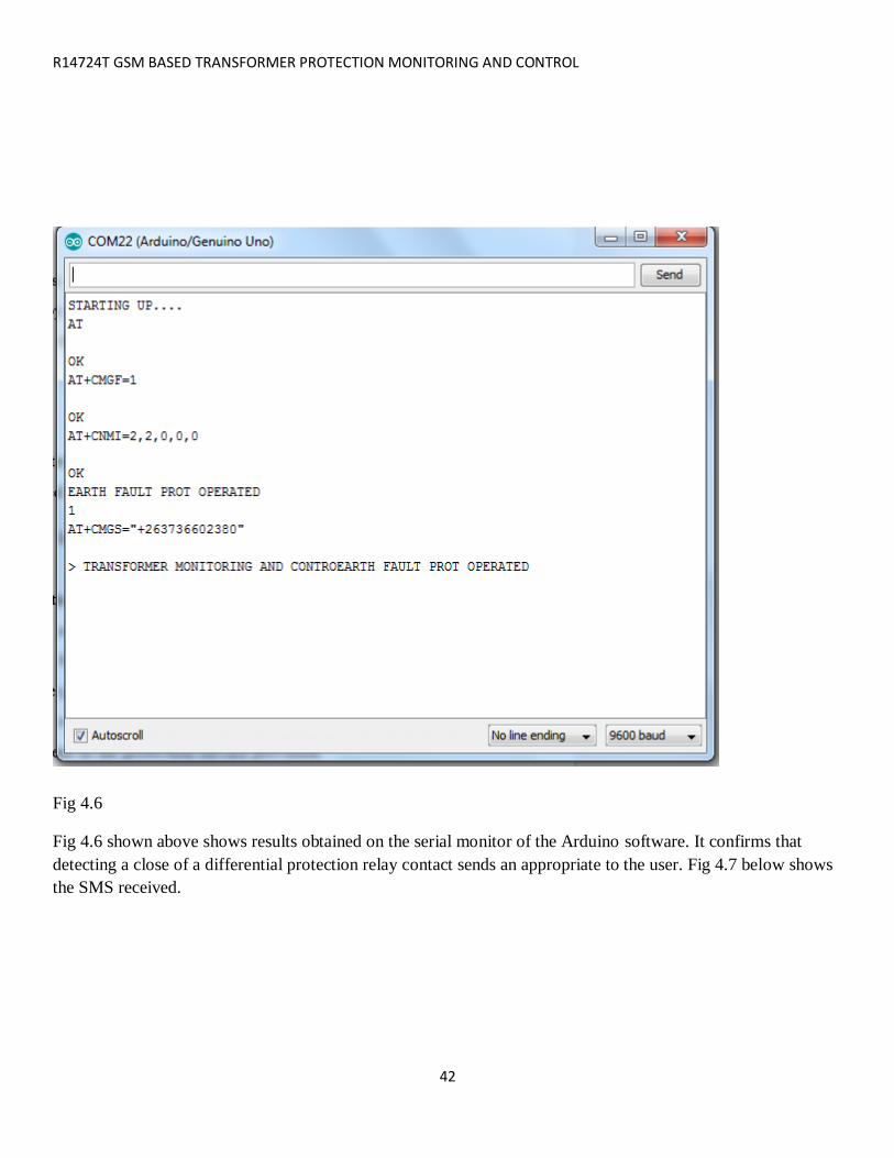
Fig 4.6
Fig 4.6 shown above shows results obtained on the serial monitor of the Arduino software. It confirms that
detecting a close of a differential protection relay contact sends an appropriate to the user. Fig 4.7 below shows
the SMS received.

R14724T GSM BASED TRANSFORMER PROTECTION MONITORING AND CONTROL
43

R14724T GSM BASED TRANSFORMER PROTECTION MONITORING AND CONTROL
44
Fig 4.8
Fig 4.8 shown above shows results obtained on the serial monitor of the Arduino software. It confirms that
detecting an overload the system will sequentially trip close of a differential protection relay contact sends an
appropriate to the user.
4.2 LIMITATIONS The system is not suitable in areas where the network is poor as this would result in unacceptable delays in the
operation of circuit breakers.
Security issues are also a concern as access to the power system can be obtained by unauthorized personnel.
There is need to build a completely shielded system so that interference from transformers is minimized.

R14724T GSM BASED TRANSFORMER PROTECTION MONITORING AND CONTROL
45
CHAPTER 5
CONCLUSION AND RECOMMENDATIONS
5.0 CONCLUSION The 33kv transformer monitoring and control module has been designed to help reduce the stress and loss of
time associated with the outages of supply due to temporary faults and overload conditions and to provide
necessary information as to the nature of fault on a transformer.
The various tests carried out and the result obtained demonstrated that the 33kv transformer monitoring and
control module achieved its design and construction aims. The system worked accordingly to specification and
quite satisfactorily. The module is relatively affordable and reliable since it is easy to operate. It is worthy to
note that this project is subject to improvements and further development.
5.1 RECOMMENDATIONS The system would benefit from development of further applications to run as add on features e.g. android
applications with end to end encryption to reduce unauthorized access.
Further development areas would be incorporating the system to use other technologies like power line carrier
systems to enhance communication in areas where the network is poor.

R14724T GSM BASED TRANSFORMER PROTECTION MONITORING AND CONTROL
46
APPENDIX
CODE
#include <DallasTemperature.h>
#include <OneWire.h>
#include <MQ2.h>
#include <DHT.h>
#define DHTPIN 9 // what digital pin we're connected to
#define DHTTYPE DHT11 // DHT 11
#include <SoftwareSerial.h>
SoftwareSerial telecel(7,8);
const int sensorPin= A0;
int smoke_level;
int PIN = 2;
int PINa = 3;
int PINb = 4;

R14724T GSM BASED TRANSFORMER PROTECTION MONITORING AND CONTROL
47
int PINc = 5;
int PINd = 13;
int PINOC = 6;
int PINDIFF = 11;
int PINEF = 12;
String msg;
int val =0;
void SendMessage();
void SerialDisplay();
String message_to_be_send;
DHT dht(DHTPIN, DHTTYPE);
void setup()
{
pinMode(sensorPin, INPUT);//the smoke sensor will be an input to the arduino
pinMode(PIN, OUTPUT);
pinMode(PINa, OUTPUT);
pinMode(PINb, OUTPUT);
pinMode(PINc, OUTPUT);
pinMode(PINd, OUTPUT);
pinMode(PINOC, INPUT_PULLUP);
pinMode(PINDIFF, INPUT);

R14724T GSM BASED TRANSFORMER PROTECTION MONITORING AND CONTROL
48
pinMode(PINEF, INPUT);
digitalWrite(PIN,LOW);
digitalWrite(PINa,LOW);
digitalWrite(PINb,LOW);
digitalWrite(PINc,LOW);
digitalWrite(PINd,LOW);
digitalWrite(PINOC,LOW);
digitalWrite(PINDIFF,LOW);
digitalWrite(PINEF,LOW);
Serial.begin(9600);
telecel.begin(9600);
delay(1000);
//Serial.flush();
Serial.println("STARTING UP....");
delay(100);
telecel.println("AT\r");
delay(1000);
telecel.println("AT+CMGF=1\r");
delay(1000);
telecel.println("AT+CNMI=2,2,0,0,0\r");
delay(1000);
if (Serial.available() > 0)

R14724T GSM BASED TRANSFORMER PROTECTION MONITORING AND CONTROL
49
{
Serial.print(Serial.read());
}
dht.begin();
}
void loop()
{
smoke_level= analogRead(sensorPin); //arduino reads the value from the smoke sensor
//Serial.print("LEVEL OF GAS DETECTED--------");
Serial.print("Gas Level ");
Serial.println(smoke_level);//prints just for debugging purposes, to see what values the sensor is picking up
delay(5000);
if(smoke_level > 150){ //if smoke level is greater than CB 1 will be switched off
digitalWrite(PIN, LOW);
message_to_be_send = "GAS RELAY OPERATED";
Serial.println("GAS RELAY OPERATED");
SendMessage();
}

R14724T GSM BASED TRANSFORMER PROTECTION MONITORING AND CONTROL
50
// Wait a few seconds between measurements.
delay(2000);
// Reading temperature or humidity takes about 250 milliseconds!
// Sensor readings may also be up to 2 seconds 'old' (its a very slow sensor)
// Read temperature as Celsius (the default)
float t = dht.readTemperature();
Serial.print("Temperature: ");
Serial.println(t);
if(t > 35){ //if temperature is greater than CB 1 will be switched off
digitalWrite(PINb, LOW);
message_to_be_send = "CB TO NEHOSHO OUT TO RELIEF OVERLOAD ON TRANSFORMER";
Serial.println("CB TO NEHOSHO OUT TO RELIEF OVERLOAD ON TRANSFORMER");
SendMessage();
delay(6000);
if (t > 35 && PINb == HIGH)
{
digitalWrite(PINc, LOW);

R14724T GSM BASED TRANSFORMER PROTECTION MONITORING AND CONTROL
51
message_to_be_send = "CB TO SENGA OUT TO RELIEF OVERLOAD ON TRANSFORMER";
Serial.println("CB TO SENGA OUT TO RELIEF OVERLOAD ON TRANSFORMER");
SendMessage();
delay(6000);
if (t > 35 && PINc == LOW)
{
digitalWrite(PINd, LOW);
message_to_be_send = "CB TO LUNDI OUT TO RELIEF OVERLOAD ON TRANSFORMER";
Serial.println("CB TO LUNDI OUT TO RELIEF OVERLOAD ON TRANSFORMER");
SendMessage();
delay(6000);
if (t > 35 && PINb == LOW && PINc == LOW && PINd == LOW)
{
digitalWrite(PIN, LOW);
message_to_be_send = " TRANSFORMER OUT ON OVERLOAD";
Serial.println("TRANSFORMER OUT ON OVERLOAD");
SendMessage();

R14724T GSM BASED TRANSFORMER PROTECTION MONITORING AND CONTROL
52
}
}
}
}
while (telecel.available()>0)
{
delay(10);
msg = telecel.readString();
delay(100);
Serial.print(msg);
if (msg.indexOf("Cb 1 On") >= 0)
{
digitalWrite(PIN, HIGH);
delay(1000);
message_to_be_send = "Cb 1 is on";
Serial.println("Cb 1 is on");
SendMessage();
}
else if (msg.indexOf("Cb 1 Off") >= 0)
{

R14724T GSM BASED TRANSFORMER PROTECTION MONITORING AND CONTROL
53
digitalWrite(PIN, LOW);
message_to_be_send = "Cb 1 is off";
Serial.println("Cb 1 is off");
SendMessage();
}
else if (msg.indexOf("Cb 2 On") >= 0)
{
digitalWrite(PINa, HIGH);
delay(1000);
message_to_be_send = "Cb 2 is on";
Serial.println("Cb 2 is on");
SendMessage();
}
else if (msg.indexOf("Cb 2 Off") >= 0)
{
digitalWrite(PINa, LOW);
message_to_be_send = "Cb 2 is off";
Serial.println("Cb 2 is off");
SendMessage();
}
else if (msg.indexOf("Cb 3 On") >= 0)
{

R14724T GSM BASED TRANSFORMER PROTECTION MONITORING AND CONTROL
54
digitalWrite(PINb, HIGH);
delay(1000);
message_to_be_send = "Cb 3 is on";
Serial.println("Cb 3 is on");
SendMessage();
}
else if (msg.indexOf("Cb 3 Off") >= 0)
{
digitalWrite(PINb, LOW);
message_to_be_send = "Cb 3 is off";
Serial.println("Cb 3 is off");
SendMessage();
}
else if (msg.indexOf("Cb 4 On") >= 0)
{
digitalWrite(PINc, HIGH);
delay(1000);
message_to_be_send = "Cb 4 is on";
SendMessage();
Serial.println("Cb 4 is on");
}
else if (msg.indexOf("Cb 4 Off") >= 0)

R14724T GSM BASED TRANSFORMER PROTECTION MONITORING AND CONTROL
55
{
digitalWrite(PINc, LOW);
message_to_be_send = "Cb 4 is off";
Serial.println("Cb 4 is off");
SendMessage();
}
else if (msg.indexOf("Cb 5 On") >= 0)
{
digitalWrite(PINd, HIGH);
delay(1000);
message_to_be_send = "Cb 5 is on";
Serial.println("Cb 5 is on");
SendMessage();
}
else if (msg.indexOf("Cb 5 Off") >= 0)
{
digitalWrite(PINd, LOW);
message_to_be_send = "Cb 5 is off";
Serial.println("Cb 5 is off");
SendMessage();
}
// else

R14724T GSM BASED TRANSFORMER PROTECTION MONITORING AND CONTROL
56
// {
// Serial.println("Enter valid command");
// message_to_be_send = "Enter valid command";
// SendMessage();
// }
SerialDisplay();
}
val = digitalRead(PINOC); // read input value
if (val == HIGH) // check if the input is HIGH
{
message_to_be_send = "OVERCURRENT PROT OPERATED";
Serial.println("OVERCURRENT PROT OPERATED");
Serial.println(val);
digitalWrite(PIN, LOW); // turn CB 1 oFF if switch is pressed
SendMessage();
}
val = digitalRead(PINDIFF); // read input value
if (val == HIGH) // check if the input is HIGH
{
message_to_be_send = "DIFFERENTIAL PROT OPERATED";

R14724T GSM BASED TRANSFORMER PROTECTION MONITORING AND CONTROL
57
Serial.println("DIFFERENTIAL PROT OPERATED");
Serial.println(val);
digitalWrite(PIN, LOW); // turn CB 1 oFF if switch is pressed
SendMessage();
}
val = digitalRead(PINEF); // read input value
if (val == HIGH) // check if the input is HIGH
{
message_to_be_send = "EARTH FAULT PROT OPERATED";
Serial.println("EARTH FAULT PROT OPERATED");
Serial.println(val);
digitalWrite(PIN, LOW); // turn CB 1 oFF if switch is pressed
SendMessage();
}
}
void SendMessage()
{
delay(1000); // Delay of 1000 milli seconds or 1 second
//telecel.println("AT+CMGS=\"+263772815072\"\r"); // Replace x with mobile number

R14724T GSM BASED TRANSFORMER PROTECTION MONITORING AND CONTROL
58
//delay(1000);
telecel.println("AT+CMGS=\"+263736602380\"\r");
delay(1000);
telecel.println("TRANSFORMER MONITORING AND CONTROL USING GSM MODULE");// The SMS
text you want to send
telecel.println("Author: L. Mutemaringa");
//telecel.print("------------------------------\n");
telecel.println(message_to_be_send);
telecel.println((char)26);// ASCII code of CTRL+Z
}
void SerialDisplay()
{
Serial.print(message_to_be_send);
}