Embed Size (px)
Citation preview
Migration of SES to FPGA Based Architectural Concepts
M. Steindl1, J. Mottok1, F. Schiller2, M. Fruechtl21Regensburg University of Applied Sciences
Department of Electronics and Information TechnologySeybothstr. 2, D-93049 Regensburg, Germany
{michael.steindl; juergen.mottok}@e-technik.fh-regensburg.de
2Technical University MunichInstitute of Information Technology in Mechanical EngineeringBoltzmannstr. 15, D-85748 Garching near Munich, Germany
{schiller; fruechtl}@itm.tum.de
Abstract
Creating diverse redundancy for fail safe or fail op-erational systems in software reduces costs for addi-tional hardware and increases flexibility. A lack ofperformance occurs by implementing a diverse soft-ware channel for e.g. floating-point operations in atraditionally microcontroller architecture. This papergives an approach for transferring the Safely Embed-ded Software (SES) into a coprocessor and to migrateSES to a flexible and powerful FPGA architecture.
1 Introduction
Embedded automotive systems use both fail safe andfail operational architectures that are mainly basedon hardware redundancy. The Safely Embedded Soft-ware (SES) approach is an alternative to save the re-dundant hardware channel by creating software di-versity [1, 4]. With SES, safety can be created in-dependently of a specific hardware or operating sys-tem. Both permanent and temporary errors can bedetected in order to initiate a suitable reaction (e.g.retry, recover, fail safe state or fail operational).
The paper is structured as follows: In Section 2,a general survey of controller technology for safety-critical systems is given. Section 3 gives an overviewof SES. The performance of the approach is analyzedin Section 4. Section 5 describes the FPGA approach.
2 Systematics of safety-critical con-troller solutions
Advancements in controller technology are accompa-nied by increasing functionality and reliability, lead-ing to an immense broadening of the application area.Consequently, the spectrum of tasks no longer in-cludes only rare controlling tasks, but more and moreresponsible challenges like safety-critical scenarios aretackled. The basic requirement for a system to beused in a safety-critical application area is to fulfillcertain safety properties. The main goal of safety-critical controllers is the recognition of erroneous data
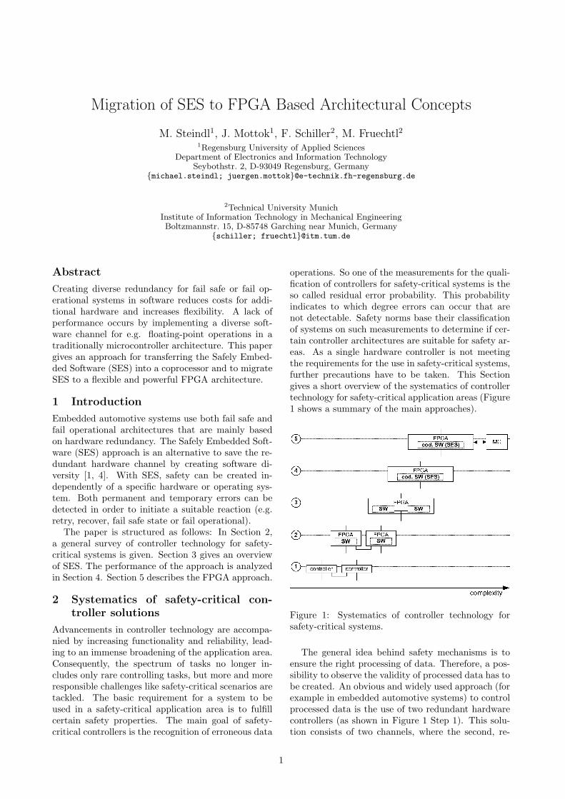
operations. So one of the measurements for the quali-fication of controllers for safety-critical systems is theso called residual error probability. This probabilityindicates to which degree errors can occur that arenot detectable. Safety norms base their classificationof systems on such measurements to determine if cer-tain controller architectures are suitable for safety ar-eas. As a single hardware controller is not meetingthe requirements for the use in safety-critical systems,further precautions have to be taken. This Sectiongives a short overview of the systematics of controllertechnology for safety-critical application areas (Figure1 shows a summary of the main approaches).
Figure 1: Systematics of controller technology forsafety-critical systems.
The general idea behind safety mechanisms is toensure the right processing of data. Therefore, a pos-sibility to observe the validity of processed data has tobe created. An obvious and widely used approach (forexample in embedded automotive systems) to controlprocessed data is the use of two redundant hardwarecontrollers (as shown in Figure 1 Step 1). This solu-tion consists of two channels, where the second, re-
1
dundant hardware channel is used to validate the re-sults of the first channel, thus allowing the recogni-tion of errors in data processing. In the case, thatboth channels provide different results, an error re-action is triggered. This error reaction often consistsof an emergency stop of the system, as it is not pos-sible to determine which of the two different resultsis the correct one. Due to this fact, the two chan-nel solution is not applicable for all safety areas. Thearchitecture can be extended to a three channel solu-tion allowing the compensation of errors on the basisof a majority decision between the results of threechannels. This type of architecture is mainly used inareas, where an emergency shutdown is not applica-ble (such as planes). Obviously, the two (respectivelythree) channel hardware approach has the disadvan-tage, that additional hardware controllers are used,meaning that depending on the particular environ-ment, this could be an unacceptable cost and spacefactor.
Instead of redundant hardware controllers, thereis the possibility of replacing those with two FPGAsrunning the logic part (software) of a controller task(as shown in Figure 1 Step 2). In comparison to hard-ware controllers, FPGAs allow a simple reconfigura-tion, thus making this architecture more flexible andcheaper. Despite of the simple reconfiguration, thisapproach shares the disadvantages of the first one.
Examining the use of two redundant hardware FP-GAs more precisely, there are basically two softwarechannels running on separate hardware channels, sothat the next logical step is the embedding of thosetwo software channels in a single hardware FPGAturning the approach into a single hardware channelsystem (Figure 1 Step 3).
Instead of using two separate, identical softwarechannels, coding mechanisms can be used to basi-cally create the second diverse software channel withinthe original software channel (Figure 1 Step 4). Onepossible approach for such a coded channel is SES,achieving the required safety properties by using cod-ing mechanisms. Starting from the original domain,diverse data is created by transferring the data andoperations to a new domain. Based on the results ofoperations in the diverse domain, the original domaincan be validated assuring the correct execution of thecontroller task. More information about the particu-lar coding mechanisms of SES can be found in Section3.
As arithmetic coding mechanisms are accompaniedby larger data values and more complex operationsin the transformation domain, those mechanisms canhave a big influence on the performance of a sys-tem (The effect of SES on the performance of a sys-tem is covered in Section 4). For a system using theone hardware channel approach with a single softwarechannel (SES), the main time-consuming factor is theSES part. This paper introduces a solution to this
matter by sourcing out the SES part to dedicatedhardware, a so called SES-coprocessor (as shown inSection 5). As a possible architecture for this solution,FPGAs are chosen. FPGAs have the advantage, thaton the one hand, the FPGA can be used to realize alogic function. But on the other hand, the FPGA canalso be used to implement a von-Neumann architec-ture, meaning that a complete microcontroller can berealized within a FPGA (a so called microcontrollersoft cores). This paper introduces a complete migra-tion of the SES architecture to a FPGA, where mi-crocontroller and SES-coprocessor are realized withina single FPGA.
3 Safely Embedded Software (SES)
This Section gives an overview of the Safely Embed-ded Software (SES) approach.
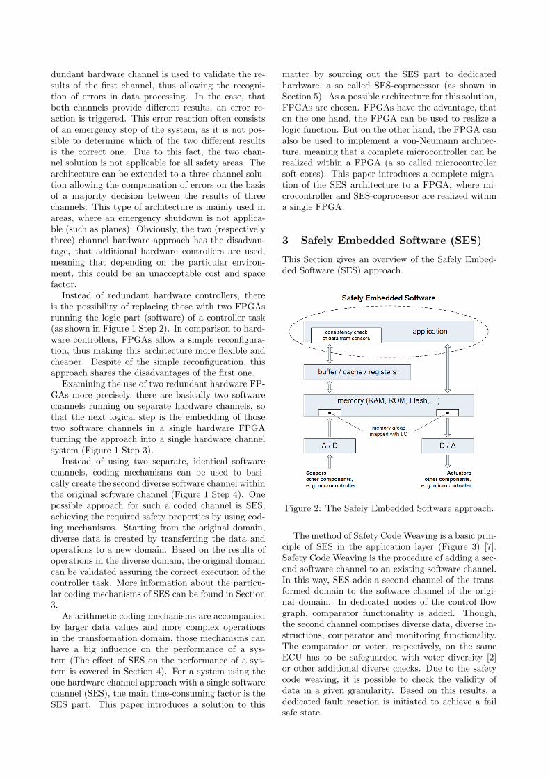
Figure 2: The Safely Embedded Software approach.
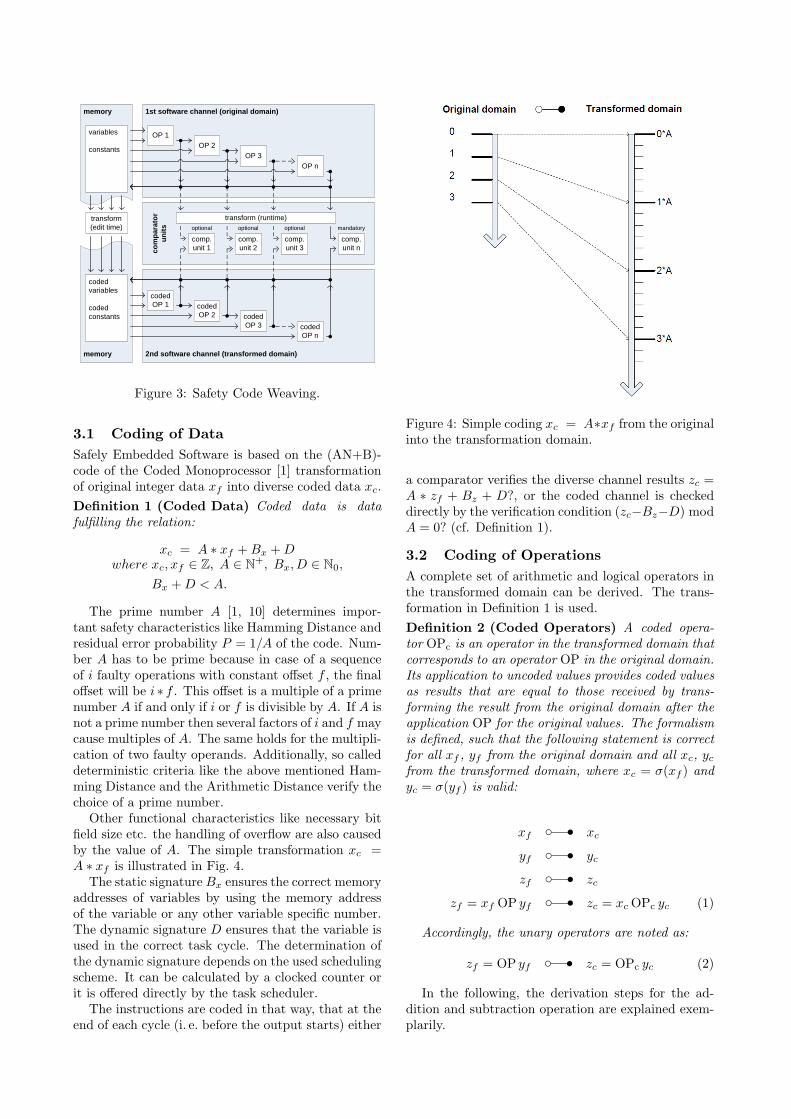
The method of Safety Code Weaving is a basic prin-ciple of SES in the application layer (Figure 3) [7].Safety Code Weaving is the procedure of adding a sec-ond software channel to an existing software channel.In this way, SES adds a second channel of the trans-formed domain to the software channel of the origi-nal domain. In dedicated nodes of the control flowgraph, comparator functionality is added. Though,the second channel comprises diverse data, diverse in-structions, comparator and monitoring functionality.The comparator or voter, respectively, on the sameECU has to be safeguarded with voter diversity [2]or other additional diverse checks. Due to the safetycode weaving, it is possible to check the validity ofdata in a given granularity. Based on this results, adedicated fault reaction is initiated to achieve a failsafe state.
variables
constants
codedvariables
codedconstants
OP 1
1st software channel (original domain)memory
OP 2
OP nOP 3
codedOP 1
2nd software channel (transformed domain)
codedOP 2
codedOP n
codedOP 3
comp.unit 1
comp.unit 2
comp.unit 3
comp.unit nco
mpa
rato
run
its
transform(edit time)
transform (runtime)
memory
optional optional optional mandatory
Figure 3: Safety Code Weaving.
3.1 Coding of DataSafely Embedded Software is based on the (AN+B)-code of the Coded Monoprocessor [1] transformationof original integer data xf into diverse coded data xc.Definition 1 (Coded Data) Coded data is datafulfilling the relation:
xc = A ∗ xf +Bx +Dwhere xc, xf ∈ Z, A ∈ N+, Bx, D ∈ N0,
Bx +D < A.
The prime number A [1, 10] determines impor-tant safety characteristics like Hamming Distance andresidual error probability P = 1/A of the code. Num-ber A has to be prime because in case of a sequenceof i faulty operations with constant offset f , the finaloffset will be i ∗ f . This offset is a multiple of a primenumber A if and only if i or f is divisible by A. If A isnot a prime number then several factors of i and f maycause multiples of A. The same holds for the multipli-cation of two faulty operands. Additionally, so calleddeterministic criteria like the above mentioned Ham-ming Distance and the Arithmetic Distance verify thechoice of a prime number.
Other functional characteristics like necessary bitfield size etc. the handling of overflow are also causedby the value of A. The simple transformation xc =A ∗ xf is illustrated in Fig. 4.
The static signatureBx ensures the correct memoryaddresses of variables by using the memory addressof the variable or any other variable specific number.The dynamic signature D ensures that the variable isused in the correct task cycle. The determination ofthe dynamic signature depends on the used schedulingscheme. It can be calculated by a clocked counter orit is offered directly by the task scheduler.
The instructions are coded in that way, that at theend of each cycle (i. e. before the output starts) either
Figure 4: Simple coding xc = A∗xf from the originalinto the transformation domain.
a comparator verifies the diverse channel results zc =A ∗ zf + Bz + D?, or the coded channel is checkeddirectly by the verification condition (zc−Bz−D) modA = 0? (cf. Definition 1).
3.2 Coding of OperationsA complete set of arithmetic and logical operators inthe transformed domain can be derived. The trans-formation in Definition 1 is used.Definition 2 (Coded Operators) A coded opera-tor OPc is an operator in the transformed domain thatcorresponds to an operator OP in the original domain.Its application to uncoded values provides coded valuesas results that are equal to those received by trans-forming the result from the original domain after theapplication OP for the original values. The formalismis defined, such that the following statement is correctfor all xf , yf from the original domain and all xc, yc
from the transformed domain, where xc = σ(xf ) andyc = σ(yf ) is valid:
xfc s xc
yfc s yc
zfc s zc
zf = xf OP yfc s zc = xc OPc yc (1)
Accordingly, the unary operators are noted as:
zf = OP yfc s zc = OPc yc (2)
In the following, the derivation steps for the ad-dition and subtraction operation are explained exem-plarily.
3.2.1 Coding of Addition
The addition is the simplest operation of the four basicarithmetic operations. Defining a coded operator (seeDefinition 2), the coded operation ⊕ is formalized asfollows:
zf = xf + yfc s zc = xc ⊕ yc (3)
Starting with the addition in the original domainand applying the formula for the inverse transforma-tion, the following equation can be obtained for zc
using 1:
zf = xf + yf
zc −Bz −DA
=xc −Bx −D
A+yc −By −D
Azc −Bz −D = xc −Bx −D + yc −By −D
zc = xc −Bx −D + yc −By +Bz
zc = xc + yc + (Bz −Bx −By)︸ ︷︷ ︸const.
−D (4)
The equations (3) and (4) state two different repre-sentations of zc. A comparison leads immediately tothe definition of the coded addition ⊕:Definition 3 (Coded Addition ⊕)
zc = xc ⊕ yc
= xc + yc + (Bz −Bx −By)−D
3.2.2 Coding of Subtraction
In analogy to the addition in Section 3.2.1, the codedoperation can be fomarlized as follows:
zf = xf − yfc s zc = xc yc (5)
Applying the formula for the inverse transfornma-tion, the following equation can be obtained for zc:
zf = xf − yf
zc −Bz −DA
=xc −Bx −D
A− yc −By −D
Azc −Bz −D = xc −Bx −D − yc +By +D
zc = xc − yc + (Bz +By −Bx)︸ ︷︷ ︸const.
+D (6)
According to this equation, the coded subtraction can be defined as follows:Definition 4 (Coded Subtraction )
zc = xc yc
= xc − yc + (Bz +By −Bx) +D
On basis of this procedure, other arithmetic oper-ations like multiplication and division can be formal-ized.
4 Performance Analysis
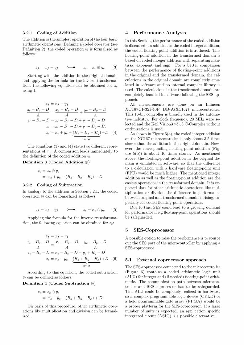
In this Section, the performance of the coded additionis discussed. In addition to the coded integer addition,the coded floating-point addition is introduced. Thisfloating-point addition in the transformed domain isbased on coded integer addition with separating man-tissa, exponent and sign. For a better comparisonbetween the performance of floating-point additionsin the original and the transformed domain, the cal-culations in the original domain are completely emu-lated in software and no internal compiler library isused. The calculations in the transformed domain arecompletely handled in software following the SES ap-proach.
All measurements are done on an InfineonXC167CI-32F40F BB-A(XC167) microcontroller.This 16-bit controller is broadly used in the automo-tive industry. For clock frequency, 20 MHz were se-lected and the Keil Vision3 v3.53 C-Compiler withoutoptimizations is used.
As shown in Figure 5(a), the coded integer additionon the XC167 microcontroller is only about 3.5 timesslower than the addition in the original domain. How-ever, the corresponding floating-point addition (Fig-ure 5(b)) is about 10 times slower. As mentionedabove, the floating-point addition in the original do-main is emulated in software, so that the differenceto a calculation with a hardware floating-point unit(FPU) would be much higher. The mentioned integeraddition as well as the floating-point addition are theeasiest operations in the transformed domain. It is ex-pected that for other arithmetic operations like mul-tiplication or division the difference in performancebetween original and transformed domain is rising, es-pecially for coded floating-point operations.
Due to this, SES could lead to a growing demandfor performance if e.g floating-point operations shouldbe safeguarded.
5 SES-Coprocessor
A possible option to raise the performance is to sourceout the SES part of the microcontroller by applying aSES-coprocessor.
5.1 External coprocessor approach
The SES-coprocessor connected to the microcontroller(Figure 6) contains a coded arithmetic logic unit(ALU) for integer and (if needed) floating-point arith-metic. The communication path between microcon-troller and SES-coprocessor has to be safeguarded.This ALU could be completely realized in hardware,so a complex programmable logic device (CPLD) ora field programmable gate array (FPGA) would bea proper platform for the SES-coprocessor. If a largenumber of units is expected, an application specificintegrated circuit (ASIC) is a possible alternative.
0
100
200
300
400
500
600
700
800
900
original operation coded operation
103 O
pera
tions
per
sec
ond
Additions per second
(a) integer additions per second
0
5
10
15
20
25
30
35
original operation coded operation
103 O
pera
tions
per
sec
ond
Additions per second
(b) floating-point additions per second
Figure 5: Performance of integer and floating-point additions in the original and coded domain on InfineonXC167CI-32F40F BB-A microcontroller
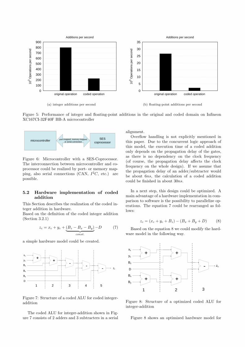
microcontroller SEScoprocessor
port-mapped, memory-mappedor serial connection
Figure 6: Microcontroller with a SES-Coprocessor.The interconnection between microcontroller and co-processor could be realized by port- or memory map-ping, also serial connections (CAN, I2C, etc.) arepossible.
5.2 Hardware implementation of codedaddition
This Section describes the realization of the coded in-teger addition in hardware.Based on the definition of the coded integer addition(Section 3.2.1)
zc = xc + yc + (Bz −Bx −By)︸ ︷︷ ︸const.
−D (7)
a simple hardware model could be created.
1 2 3
xc
yc
Bz
D
Bx
By
zc
4 5
Figure 7: Structure of a coded ALU for coded integer-addition
The coded ALU for integer-addition shown in Fig-ure 7 consists of 2 adders and 3 subtracters in a serial
alignment.Overflow handling is not explicitly mentioned in
this paper. Due to the concurrent logic approach ofthis model, the execution time of a coded additiononly depends on the propagation delay of the gates,as there is no dependency on the clock frequency(of course, the propagation delay affects the clockfrequency on the whole design). If we assume thatthe propagation delay of an adder/subtracter wouldbe about 6ns, the calculation of a coded additioncould be finished in about 30ns.
In a next step, this design could be optimized. Amain advantage of a hardware implementation in com-parison to software is the possibility to parallelize op-erations. The equation 7 could be rearranged as fol-lows:
zc = (xc + yc +Bz)− (Bx +By +D) (8)
Based on the equation 8 we could modify the hard-ware model in the following way.
1 2 3
xc
yc
Bz
D
Bx
By
zc
Figure 8: Structure of a optimized coded ALU forinteger-addition
Figure 8 shows an optimized hardware model for
a coded integer addition. In contrast to Figure 7,this ALU consists of 4 adders and 1 subtracter, twoadditions are done parallel in stage 1 and 2. Due tothis, the calculation time of the coded addition isreduced to 18ns in this way.
With this SES-coprocessor approach, the perfor-mance of the system could be increased, but on theother hand additional hardware is needed.
5.3 Migration to a FPGA architectureFPGAs allow a flexible, low-cost solution for controlfunctions, bridging an interface between componentsor simply as glue logic for a variety of customized sys-tems. Multiple functions could be integrated into asingle-chip solution to reduce board space and costs[3]. Many FPGA vendors provide powerful microcon-troller soft cores so it would be obvious to integratethe microcontroller and the SES-coprocessor on a sin-gle FPGA.
5.3.1 Single core processor with SES
State of the art FPGAs contain either hardwired mi-crocontrollers (e.g. Xilinx Virtex 4) or a microcon-troller soft core could be implemented.
FPGA
µC
SES
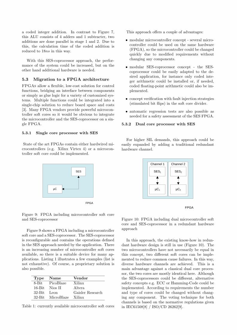
Figure 9: FPGA including microcontroller soft coreand SES-coprocessor
Figure 9 shows a FPGA including a microcontrollersoft core and a SES-coprocessor. The SES-coprocessoris reconfigurable and contains the operations definedin the SES approach needed by the application. Thereis an increasing number of microcontroller soft coresavailable, so there is a suitable device for many ap-plications. Listing 1 illustrates a few examples (list isnot exhaustive). Of course, a proprietary solution isalso possible.
Type Name Vendor8-Bit PicoBlaze Xilinx16-Bit Nios II Altera32-Bit Leon Gaisler Research32-Bit MicroBlaze Xilinx
Table 1: currently available microcontroller soft cores
This approach offers a couple of advantages:
• modular microcontroller concept - several micro-controller could be used on the same hardware(FPGA), so the microcontroller could be changedquickly due to modified requirements withoutchanging any components.
• modular SES-coprocessor concept - the SES-coprocessor could be easily adapted to the de-sired application, for instance only coded inte-ger arithmetic could be installed or, if needed,coded floating-point arithmetic could also be im-plemented.
• concept verification with fault injection strategies(stimulated bit flips) in the soft core divider.
• automatic regression tests are also possible asneeded for a safety assessment of the SES FPGA.
5.3.2 Dual core processor with SES
For higher SIL demands, this approach could beeasily expanded by adding a traditional redundanthardware channel.
FPGA
µC1
SES1
µC2
SES2
Channel 1 Channel 2
Figure 10: FPGA including dual microcontroller softcore and SES-coprocessor in a redundant hardwareapproach
In this approach, the existing know-how in redun-dant hardware design is still in use (Figure 10). Thetwo microcontrollers have not necessarily be equal inthis concept, two different soft cores can be imple-mented to reduce common cause failures. In this way,diverse hardware channels are achieved. This is amain advantage against a classical dual core proces-sor, the two cores are mostly identical here. Althoughthe SES-coprocessors could be different, alternativesafety concepts e.g. ECC or Hamming-Code could beimplemented. According to requirements the numberand type of cores could be changed without chang-ing any component. The voting technique for bothchannels is based on the normative regulations givenin IEC61508[8] / ISO/CD 26262[9].
5.3.3 Further options to increase the perfor-mance
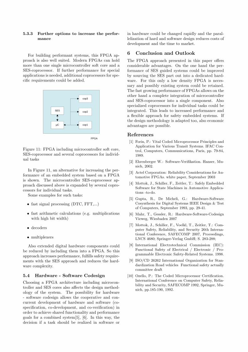
For building performant systems, this FPGA ap-proach is also well suited. Modern FPGAs can holdmore than one single microcontroller soft core and aSES-coprocessor. If further performance for specialapplications is needed, additional coprocessors for spe-cific requirements could be added.
FPGA
µC
SES cop2
cop1
cop3
Figure 11: FPGA including microcontroller soft core,SES-coprocessor and several coprocessors for individ-ual tasks
In Figure 11, an alternative for increasing the per-formance of an embedded system based on a FPGAis shown. The microcontroller SES-coprocessor ap-proach discussed above is expanded by several copro-cessors for individual tasks.
Some examples for such tasks:
• fast signal processing (DTC, FFT,...)
• fast arithmetic calculations (e.g. multiplicationswith high bit width)
• decoders
• multiplexers
Also extended digital hardware components couldbe reduced by including them into a FPGA. So thisapproach increases performance, fulfills safety require-ments with the SES approach and reduces the hard-ware complexity.
5.4 Hardware - Software CodesignChoosing a FPGA architecture including microcon-troller and SES cores also affects the design method-ology of the system. The possibility for hardware- software codesign allows the cooperative and con-current development of hardware and software (co-specification, co-development, and co-verification) inorder to achieve shared functionality and performancegoals for a combined system[5], [6]. In this way, thedecision if a task should be realized in software or
in hardware could be changed rapidly and the paral-lelization of hard and software design reduces costs ofdevelopment and the time to market.
6 Conclusion and Outlook
The FPGA approach presented in this paper offersconsiderable advantages. On the one hand the per-formance of SES guided systems could be improvedby sourcing the SES part out into a dedicated hard-ware. For this only a low density FPGA is neces-sary and possibly existing system could be retained.The fast growing performance of FPGAs allows on theother hand a complete integration of microcontrollerand SES-coprocessor into a single component. Alsospecialized coprocessors for individual tasks could beintegrated. This leads to increased performance anda flexible approach for safety embedded systems. Ifthe design methodology is adapted too, also economicadvantages are possible.
References
[1] Forin, P.: Vital Coded Microprocessor Principles andApplication for Various Transit Systems. IFAC Con-trol, Computers, Communications, Paris, pp. 79-84,1989.
[2] Ehrenberger W.: Software-Verifikation. Hanser, Mu-nich, 2002.
[3] Actel Corporation: Reliability Considerations for Au-tomotive FPGAs. white paper, September 2003
[4] Mottok, J., Schiller, F., Zeitler, T.: Safely EmbeddedSoftware for State Machines in Automotive Applica-tions -to-do.
[5] Gupta, R., De Micheli, G.: Hardware-SoftwareCosynthesis for Digital Systems IEEE Design & Testof Computers, September 1993, pp. 29-41.
[6] Mahr, T., Gessler, R.: Hardware-Software-CodesignVieweg, Wiesbaden 2007
[7] Mottok, J., Schiller, F., Voelkl, T., Zeitler, T.: Com-puter Safety, Reliability, and Security 26th Interna-tional Conference, SAFECOMP 2007, Proceedings,LNCS 4680; Springer-Verlag GmbH; S. 283-288;
[8] International Electrotechnical Commission (IEC):Functional Safety of Electrical / Electronic / Pro-grammable Electronic Safety-Related Systems. 1998.
[9] ISO/CD 26262 International Organization for Stan-dardization Road vehicles Functional safety actuallycommittee draft
[10] Ozello, P.: The Coded Microprocessor Certification.International Conference on Computer Safety, Relia-bility and Security, SAFECOMP 1992, Springer, Mu-nich, pp.185-190, 1992.