Embed Size (px)
Citation preview
Product # MCOTS-C-28-1R2-SM Phone 1-888-567-9596 www.synqor.com Doc.# 005-0005339 Rev. D 05/04/10 Page 1
MCOTS-C-28-1R2-SMSingle Output
Sixteenth-brick
The MilQor series of Mil-COTS DC/DC converters brings SynQor’s field proven high-efficiency synchronous rectification technology to the Military/Aerospace industry. SynQor’s ruggedized encased packaging approach ensures survivability in demanding environments. Compatible with the industry standard format, these converters operate at a fixed frequency, and follow conservative component derating guidelines. They are designed and manufactured to comply with a wide range of military standards.
Full Power Operation: -55°C to +100°C
Mil-COTS
MILITARY COTS DC/DC CONVERTER
Designed and Manufactured in the USA
16-40V 16-50V 1.2V 25A 79% @ 12.5A / 79% @ 25AContinuous Input Transient Input Output Output Efficiency
Protection Features
• Input under-voltage lockout• Output current limit and short circuit protection• Active back bias limit• Output over-voltage protection• Thermal shutdown
Screening/Qualification
• AS9100 and ISO 9001:2008 certified facility• Qualification consistent with MIL-STD-883• Available with S-Grade or M-Grade screening• Temperature cycling per MIL-STD-883, Method 1010,
Condition B, 10 cycles• Burn-In at 100C baseplate temperature• Final visual inspection per MIL-STD-2008• Full component traceability
Operational Features
Mechanical Features
Control Features
Safety Features• High efficiency, 79% at full rated load current• Operating input voltage range: 16-40V• Fixed frequency switching provides predictable EMI• No minimum load requirement
• On/Off control referenced to input return• Remote sense for the output voltage• Output voltage trim range of +10%, -10%
• 2250V, 30 MΩ input-to-output isolation• Certified 60950-1 requirement for basic insulation
(see Standards and Qualifications page)
• Industry standard sixteenth-brick pin-out configuration• Size: 1.04” x 1.44” x 0.50”
(26.3 x 36.5 x 12.7 mm)• Total weight: 1.14oz (32.3g)• Flanged baseplate version available
MCOTS-C-28-1R2-SM-N-M
DC/DC CONVERTER
28VIN 1.2VOUT
@ 25A
Technical Specification
Product # MCOTS-C-28-1R2-SM Phone 1-888-567-9596 www.synqor.com Doc.# 005-0005339 Rev. D 05/04/10 Page 2
MCOTS-C-28-1R2-SMOutput: 1.2V
Current: 25A
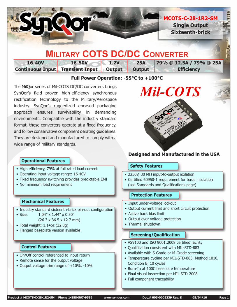
BLOCK DIAGRAM
TYPICAL CONNECTION DIAGRAM
VinExternal Input Filter
Trim
Vin(+)
Iload
Cload
Vout(+)
Rtrim-up
or
Rtrim-down
Vsense(+)
ON/OFF
Vin(_) Vout(_)
Vsense(_)
ElectrolyticCapacitor
POSITIVE INPUT
INPUTRETURN
POSITIVE OUTPUT
OUTPUTRETUN
PRIMARYCONTROL
SECONDARYCONTROLUVLO
ON/OFF
CURRENTSENSE
CURRENTLIMT
- SENSE
+ SENSE
TRIMIS
OLA
TIO
N B
ARR
IER
GATE CONTROL
GATE CONTROL
GATE DRIVER
GATE DRIVER
Technical Specification
Product # MCOTS-C-28-1R2-SM Phone 1-888-567-9596 www.synqor.com Doc.# 005-0005339 Rev. D 05/04/10 Page 3
MCOTS-C-28-1R2-SMOutput: 1.2V
Current: 25A
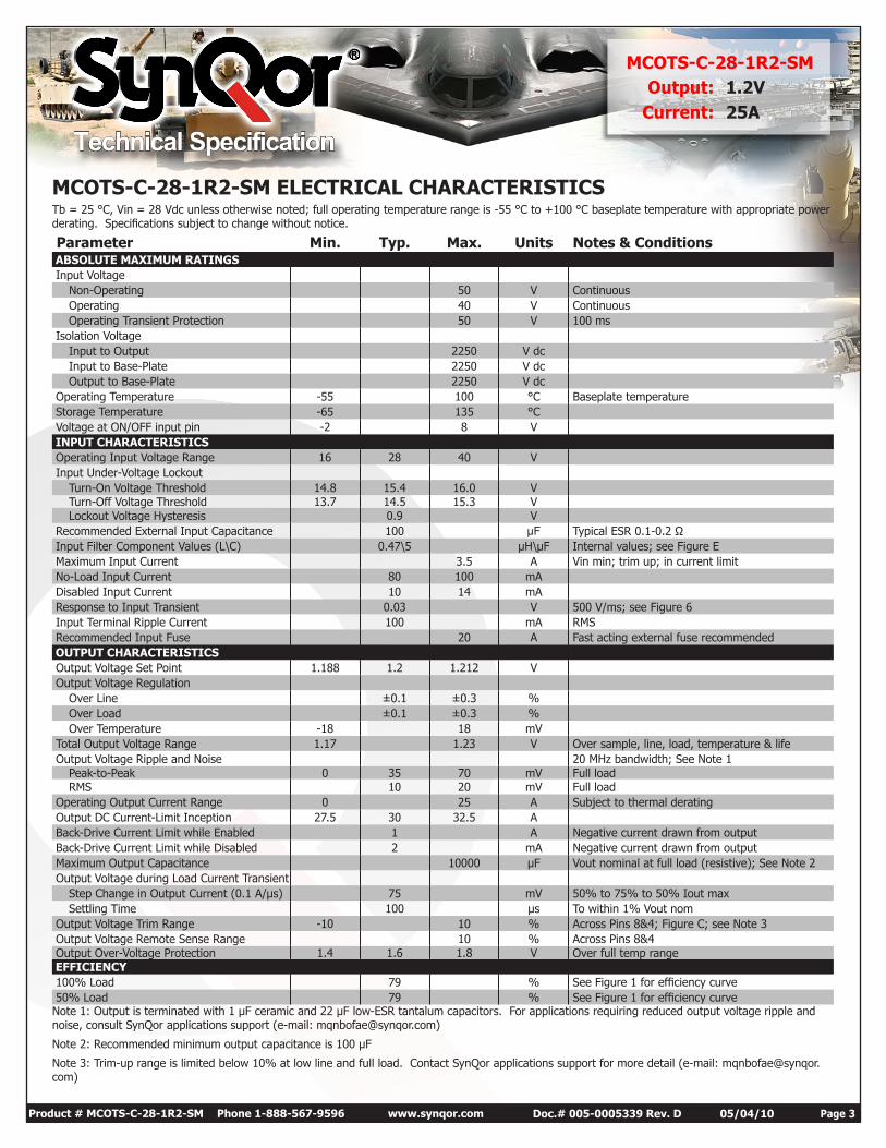
MCOTS-C-28-1R2-SM ELECTRICAL CHARACTERISTICSTb = 25 °C, Vin = 28 Vdc unless otherwise noted; full operating temperature range is -55 °C to +100 °C baseplate temperature with appropriate power derating. Specifications subject to change without notice.
Parameter Min. Typ. Max. Units Notes & Conditions ABSOLUTE MAXIMUM RATINGS Input Voltage
Non-Operating 50 V Continuous Operating 40 V Continuous Operating Transient Protection 50 V 100 ms
Isolation Voltage Input to Output 2250 V dc Input to Base-Plate 2250 V dc Output to Base-Plate 2250 V dc
Operating Temperature -55 100 °C Baseplate temperature Storage Temperature -65 135 °C Voltage at ON/OFF input pin -2 8 V INPUT CHARACTERISTICS Operating Input Voltage Range 16 28 40 V Input Under-Voltage Lockout
Turn-On Voltage Threshold 14.8 15.4 16.0 V Turn-Off Voltage Threshold 13.7 14.5 15.3 V Lockout Voltage Hysteresis 0.9 V
Recommended External Input Capacitance 100 µF Typical ESR 0.1-0.2 Ω Input Filter Component Values (L\C) 0.47\5 µH\µF Internal values; see Figure E Maximum Input Current 3.5 A Vin min; trim up; in current limit No-Load Input Current 80 100 mA Disabled Input Current 10 14 mA Response to Input Transient 0.03 V 500 V/ms; see Figure 6 Input Terminal Ripple Current 100 mA RMS Recommended Input Fuse 20 A Fast acting external fuse recommended OUTPUT CHARACTERISTICS Output Voltage Set Point 1.188 1.2 1.212 V Output Voltage Regulation
Over Line ±0.1 ±0.3 % Over Load ±0.1 ±0.3 % Over Temperature -18 18 mV
Total Output Voltage Range 1.17 1.23 V Over sample, line, load, temperature & life Output Voltage Ripple and Noise 20 MHz bandwidth; See Note 1
Peak-to-Peak 0 35 70 mV Full load RMS 10 20 mV Full load
Operating Output Current Range 0 25 A Subject to thermal derating Output DC Current-Limit Inception 27.5 30 32.5 A Back-Drive Current Limit while Enabled 1 A Negative current drawn from output Back-Drive Current Limit while Disabled 2 mA Negative current drawn from output Maximum Output Capacitance 10000 µF Vout nominal at full load (resistive); See Note 2 Output Voltage during Load Current Transient
Step Change in Output Current (0.1 A/µs) 75 mV 50% to 75% to 50% Iout max Settling Time 100 µs To within 1% Vout nom
Output Voltage Trim Range -10 10 % Across Pins 8&4; Figure C; see Note 3 Output Voltage Remote Sense Range 10 % Across Pins 8&4 Output Over-Voltage Protection 1.4 1.6 1.8 V Over full temp range EFFICIENCY 100% Load 79 % See Figure 1 for efficiency curve 50% Load 79 % See Figure 1 for efficiency curveNote 1: Output is terminated with 1 µF ceramic and 22 µF low-ESR tantalum capacitors. For applications requiring reduced output voltage ripple and noise, consult SynQor applications support (e-mail: [email protected])
Note 2: Recommended minimum output capacitance is 100 µF
Note 3: Trim-up range is limited below 10% at low line and full load. Contact SynQor applications support for more detail (e-mail: [email protected])
Technical Specification
Product # MCOTS-C-28-1R2-SM Phone 1-888-567-9596 www.synqor.com Doc.# 005-0005339 Rev. D 05/04/10 Page 4
MCOTS-C-28-1R2-SMOutput: 1.2V
Current: 25A
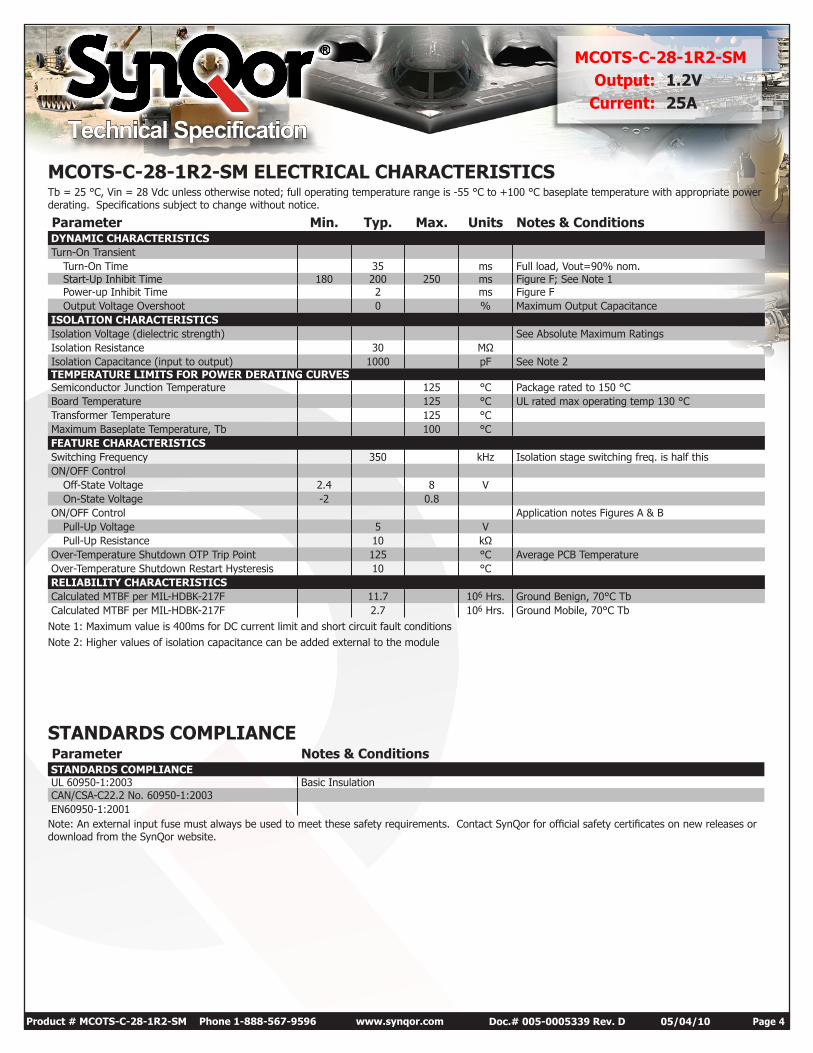
MCOTS-C-28-1R2-SM ELECTRICAL CHARACTERISTICSTb = 25 °C, Vin = 28 Vdc unless otherwise noted; full operating temperature range is -55 °C to +100 °C baseplate temperature with appropriate power derating. Specifications subject to change without notice.
Parameter Min. Typ. Max. Units Notes & Conditions DYNAMIC CHARACTERISTICS Turn-On Transient
Turn-On Time 35 ms Full load, Vout=90% nom. Start-Up Inhibit Time 180 200 250 ms Figure F; See Note 1 Power-up Inhibit Time 2 ms Figure F Output Voltage Overshoot 0 % Maximum Output Capacitance
ISOLATION CHARACTERISTICS Isolation Voltage (dielectric strength) See Absolute Maximum Ratings Isolation Resistance 30 MΩ Isolation Capacitance (input to output) 1000 pF See Note 2 TEMPERATURE LIMITS FOR POWER DERATING CURVES Semiconductor Junction Temperature 125 °C Package rated to 150 °C Board Temperature 125 °C UL rated max operating temp 130 °C Transformer Temperature 125 °C Maximum Baseplate Temperature, Tb 100 °C FEATURE CHARACTERISTICS Switching Frequency 350 kHz Isolation stage switching freq. is half this ON/OFF Control
Off-State Voltage 2.4 8 V On-State Voltage -2 0.8
ON/OFF Control Application notes Figures A & B Pull-Up Voltage 5 V Pull-Up Resistance 10 kΩ
Over-Temperature Shutdown OTP Trip Point 125 °C Average PCB Temperature Over-Temperature Shutdown Restart Hysteresis 10 °C RELIABILITY CHARACTERISTICS Calculated MTBF per MIL-HDBK-217F 11.7 106 Hrs. Ground Benign, 70°C Tb Calculated MTBF per MIL-HDBK-217F 2.7 106 Hrs. Ground Mobile, 70°C TbNote 1: Maximum value is 400ms for DC current limit and short circuit fault conditionsNote 2: Higher values of isolation capacitance can be added external to the module
STANDARDS COMPLIANCE Parameter Notes & Conditions STANDARDS COMPLIANCE UL 60950-1:2003 Basic Insulation CAN/CSA-C22.2 No. 60950-1:2003 EN60950-1:2001Note: An external input fuse must always be used to meet these safety requirements. Contact SynQor for official safety certificates on new releases or download from the SynQor website.
Technical Specification
Product # MCOTS-C-28-1R2-SM Phone 1-888-567-9596 www.synqor.com Doc.# 005-0005339 Rev. D 05/04/10 Page 5
MCOTS-C-28-1R2-SMOutput: 1.2V
Current: 25A
60
65
70
75
80
85
90
95
100
0 5 10 15 20 25Load Current (A)
Effic
ienc
y (%
)
16 Vin
28 Vin
40 Vin
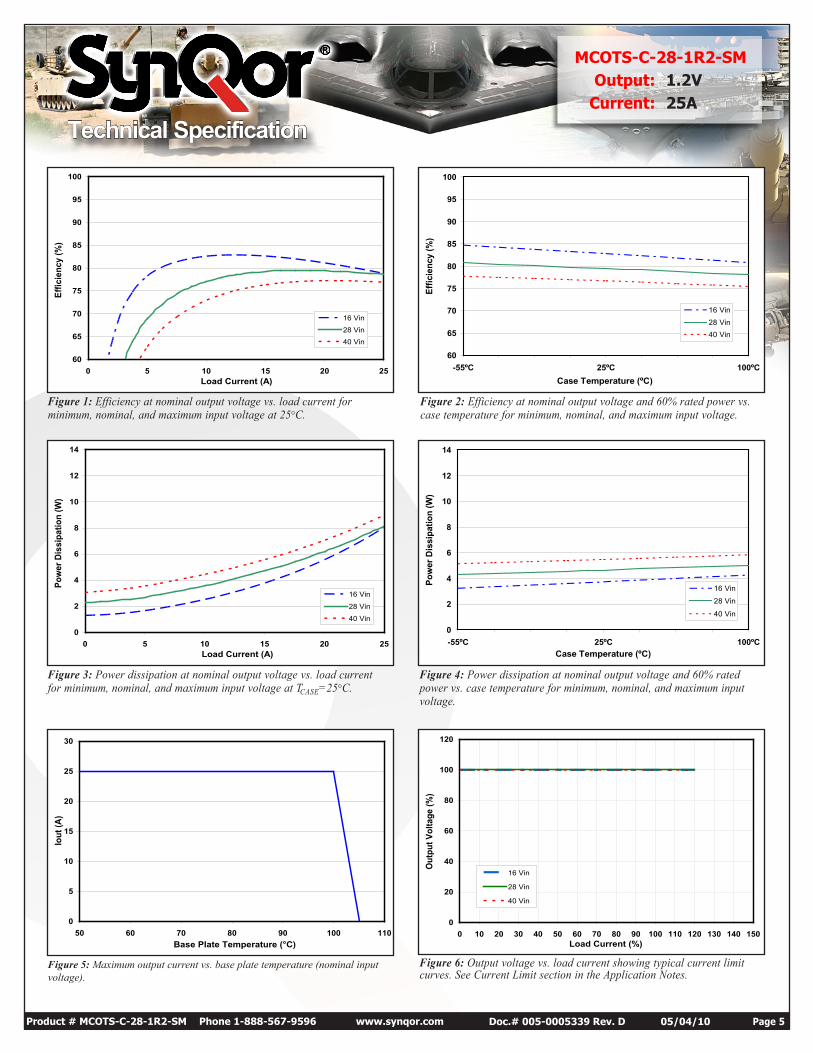
Figure 1: Efficiency at nominal output voltage vs. load current for minimum, nominal, and maximum input voltage at 25°C.
Figure 2: Efficiency at nominal output voltage and 60% rated power vs. case temperature for minimum, nominal, and maximum input voltage.
Figure 3: Power dissipation at nominal output voltage vs. load current for minimum, nominal, and maximum input voltage at TCASE=25°C.
Figure 4: Power dissipation at nominal output voltage and 60% rated power vs. case temperature for minimum, nominal, and maximum input voltage.
Figure 6: Output voltage vs. load current showing typical current limit curves. See Current Limit section in the Application Notes.
60
65
70
75
80
85
90
95
100
-55ºC 25ºC 100ºCCase Temperature (ºC)
Effic
ienc
y (%
)
16 Vin
28 Vin40 Vin
0
2
4
6
8
10
12
14
-55ºC 25ºC 100ºCCase Temperature (ºC)
Pow
er D
issi
patio
n (W
)
16 Vin
28 Vin
40 Vin
0
2
4
6
8
10
12
14
0 5 10 15 20 25Load Current (A)
Pow
er D
issi
patio
n (W
)
16 Vin
28 Vin
40 Vin
0
20
40
60
80
100
120
0 10 20 30 40 50 60 70 80 90 100 110 120 130 140 150Load Current (%)
Out
put V
olta
ge (%
)
16 Vin
28 Vin
40 Vin
Figure 5: Maximum output current vs. base plate temperature (nominal input voltage).
0
5
10
15
20
25
30
50 60 70 80 90 100 110Base Plate Temperature (°C)
Iout
(A)
Technical Specification
Product # MCOTS-C-28-1R2-SM Phone 1-888-567-9596 www.synqor.com Doc.# 005-0005339 Rev. D 05/04/10 Page 6
MCOTS-C-28-1R2-SMOutput: 1.2V
Current: 25A
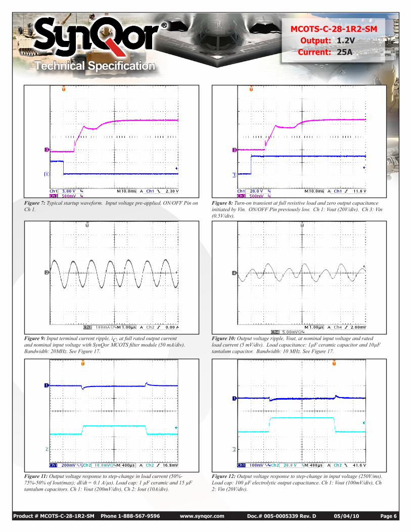
Figure 9: Input terminal current ripple, iC, at full rated output current and nominal input voltage with SynQor MCOTS filter module (50 mA/div). Bandwidth: 20MHz. See Figure 17.
Figure 10: Output voltage ripple, Vout, at nominal input voltage and rated load current (5 mV/div). Load capacitance: 1µF ceramic capacitor and 10µF tantalum capacitor. Bandwidth: 10 MHz. See Figure 17.
Figure 12: Output voltage response to step-change in input voltage (250V/ms). Load cap: 100 µF electrolytic output capacitance. Ch 1: Vout (100mV/div), Ch 2: Vin (20V/div).
Figure 11: Output voltage response to step-change in load current (50%-75%-50% of Iout(max); dI/dt = 0.1 A/µs). Load cap: 1 µF ceramic and 15 µF tantalum capacitors. Ch 1: Vout (200mV/div), Ch 2: Iout (10A/div).
Figure 8: Turn-on transient at full resistive load and zero output capacitance initiated by Vin. ON/OFF Pin previously low. Ch 1: Vout (20V/div). Ch 3: Vin (0.5V/div).
Figure 7: Typical startup waveform. Input voltage pre-applied, ON/OFF Pin on Ch 1.
Technical Specification
Product # MCOTS-C-28-1R2-SM Phone 1-888-567-9596 www.synqor.com Doc.# 005-0005339 Rev. D 05/04/10 Page 7
MCOTS-C-28-1R2-SMOutput: 1.2V
Current: 25A
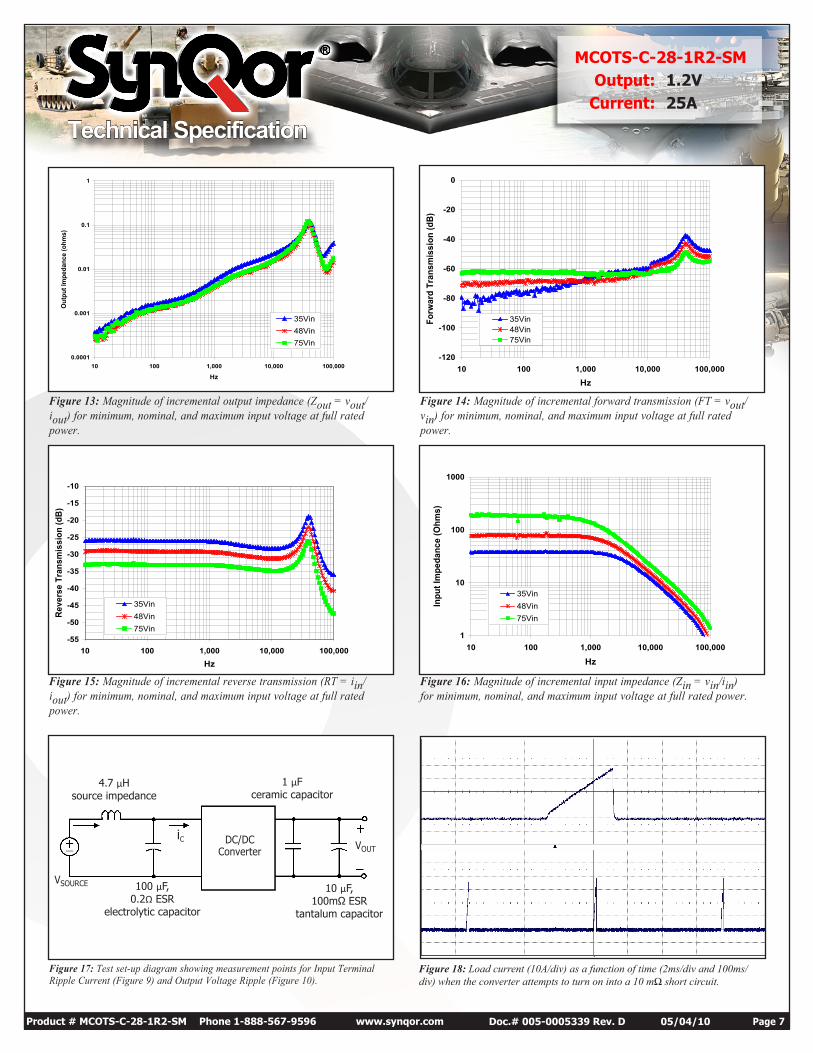
Figure 13: Magnitude of incremental output impedance (Zout = vout/iout) for minimum, nominal, and maximum input voltage at full rated power.
Figure 14: Magnitude of incremental forward transmission (FT = vout/vin) for minimum, nominal, and maximum input voltage at full rated power.
Figure 15: Magnitude of incremental reverse transmission (RT = iin/iout) for minimum, nominal, and maximum input voltage at full rated power.
Figure 16: Magnitude of incremental input impedance (Zin = vin/iin) for minimum, nominal, and maximum input voltage at full rated power.
Figure 17: Test set-up diagram showing measurement points for Input Terminal Ripple Current (Figure 9) and Output Voltage Ripple (Figure 10).
DC/DCConverter
VSOURCE
iCVOUT
0.0001
0.001
0.01
0.1
1
10 100 1,000 10,000 100,000
Hz
Out
put I
mpe
danc
e (o
hms)
35Vin48Vin75Vin
1
10
100
1000
10 100 1,000 10,000 100,000
Hz
Inpu
t Im
peda
nce
(Ohm
s)
35Vin48Vin75Vin
-120
-100
-80
-60
-40
-20
0
10 100 1,000 10,000 100,000
Hz
Forw
ard
Tran
smis
sion
(dB)
35Vin48Vin75Vin
-55
-50
-45
-40
-35
-30
-25
-20
-15
-10
10 100 1,000 10,000 100,000Hz
Reve
rse
Tran
smis
sion
(dB)
35Vin48Vin75Vin
4.7 µHsource impedance
100 µF,0.2Ω ESR
electrolytic capacitor
10 µF,100mΩ ESR
tantalum capacitor
1 µFceramic capacitor
Figure 18: Load current (10A/div) as a function of time (2ms/div and 100ms/div) when the converter attempts to turn on into a 10 mΩ short circuit.
Technical Specification
Product # MCOTS-C-28-1R2-SM Phone 1-888-567-9596 www.synqor.com Doc.# 005-0005339 Rev. D 05/04/10 Page 8
MCOTS-C-28-1R2-SMOutput: 1.2V
Current: 25A
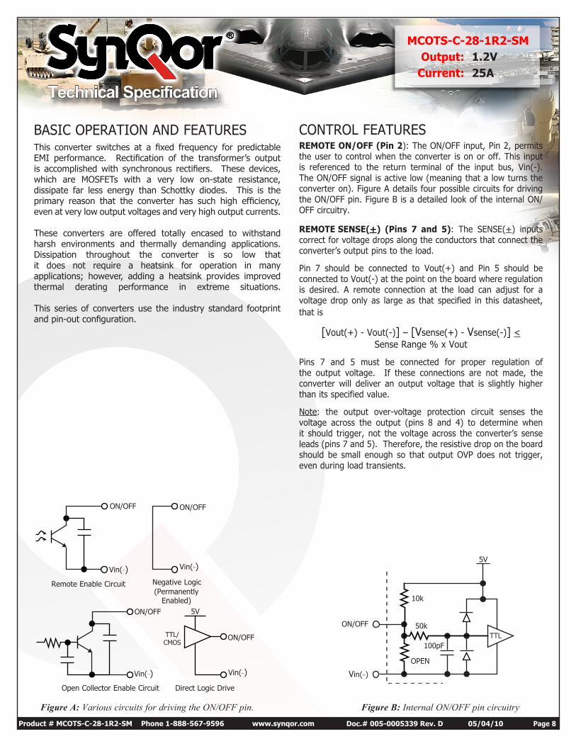
Figure A: Various circuits for driving the ON/OFF pin. Figure B: Internal ON/OFF pin circuitry
TTL
5V
50k
10k
ON/OFF
Vin(_)
100pF
Open Collector Enable Circuit
Remote Enable Circuit
Direct Logic Drive
Negative Logic (Permanently
Enabled)
ON/OFF
Vin(_)
ON/OFF
ON/OFF
Vin(_)
ON/OFF
5V
TTL/ CMOS
Vin(_)
Vin(_)OPEN
This converter switches at a fixed frequency for predictable EMI performance. Rectification of the transformer’s output is accomplished with synchronous rectifiers. These devices, which are MOSFETs with a very low on-state resistance, dissipate far less energy than Schottky diodes. This is the primary reason that the converter has such high efficiency, even at very low output voltages and very high output currents. These converters are offered totally encased to withstand harsh environments and thermally demanding applications. Dissipation throughout the converter is so low that it does not require a heatsink for operation in many applications; however, adding a heatsink provides improved thermal derating performance in extreme situations. This series of converters use the industry standard footprint and pin-out configuration.
BASIC OPERATION AND FEATURES CONTROL FEATURESREMOTE ON/OFF (Pin 2): The ON/OFF input, Pin 2, permits the user to control when the converter is on or off. This input is referenced to the return terminal of the input bus, Vin(-). The ON/OFF signal is active low (meaning that a low turns the converter on). Figure A details four possible circuits for driving the ON/OFF pin. Figure B is a detailed look of the internal ON/OFF circuitry.
REMOTE SENSE(+) (Pins 7 and 5): The SENSE(+) inputs correct for voltage drops along the conductors that connect the converter’s output pins to the load.
Pin 7 should be connected to Vout(+) and Pin 5 should be connected to Vout(-) at the point on the board where regulation is desired. A remote connection at the load can adjust for a voltage drop only as large as that specified in this datasheet, that is
[Vout(+) - Vout(-)] – [Vsense(+) - Vsense(-)] < Sense Range % x Vout
Pins 7 and 5 must be connected for proper regulation of the output voltage. If these connections are not made, the converter will deliver an output voltage that is slightly higher than its specified value.
Note: the output over-voltage protection circuit senses the voltage across the output (pins 8 and 4) to determine when it should trigger, not the voltage across the converter’s sense leads (pins 7 and 5). Therefore, the resistive drop on the board should be small enough so that output OVP does not trigger, even during load transients.
Technical Specification
Product # MCOTS-C-28-1R2-SM Phone 1-888-567-9596 www.synqor.com Doc.# 005-0005339 Rev. D 05/04/10 Page 9
MCOTS-C-28-1R2-SMOutput: 1.2V
Current: 25A
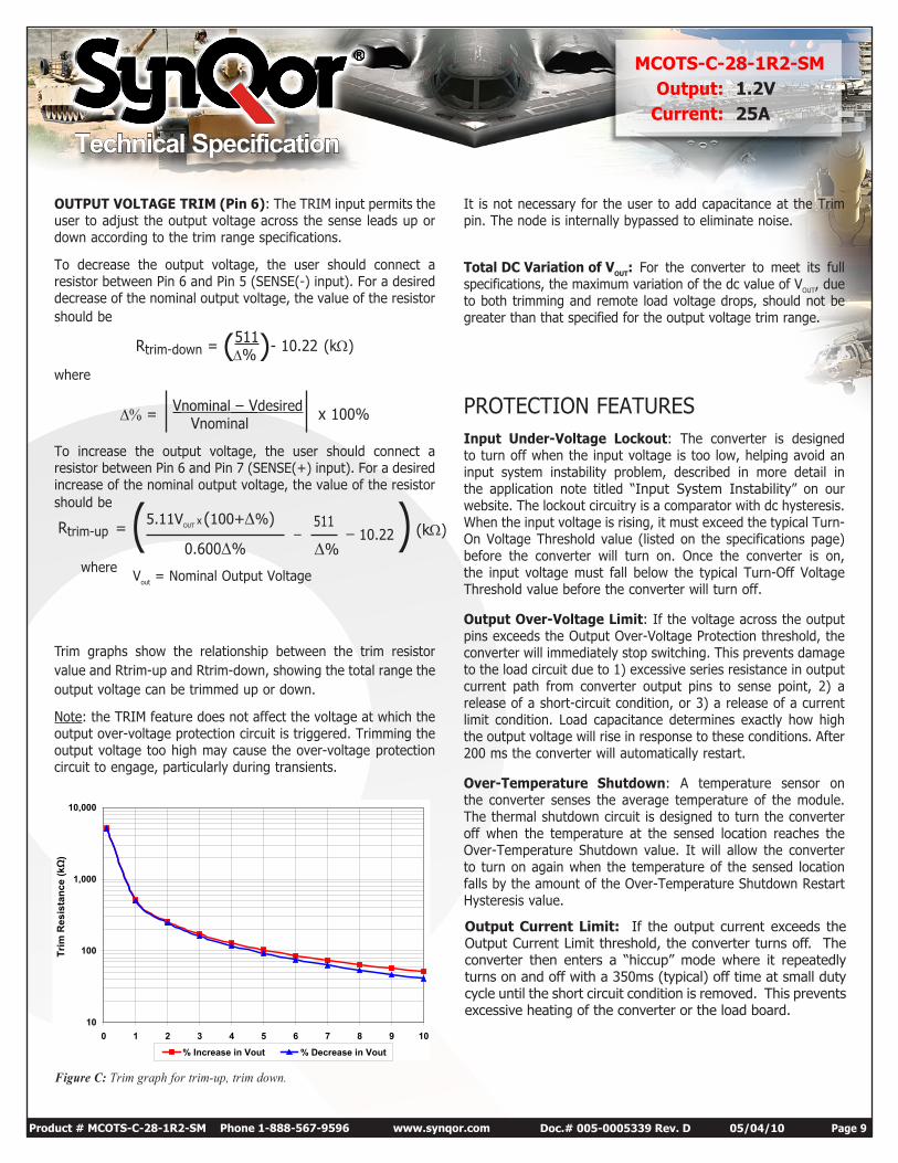
OUTPUT VOLTAGE TRIM (Pin 6): The TRIM input permits the user to adjust the output voltage across the sense leads up or down according to the trim range specifications.
To decrease the output voltage, the user should connect a resistor between Pin 6 and Pin 5 (SENSE(-) input). For a desired decrease of the nominal output voltage, the value of the resistor should be
Rtrim-down = (511)- 10.22 (kW)D%where
D% = Vnominal – Vdesired x 100% Vnominal
To increase the output voltage, the user should connect a resistor between Pin 6 and Pin 7 (SENSE(+) input). For a desired increase of the nominal output voltage, the value of the resistor should be
Trim graphs show the relationship between the trim resistor value and Rtrim-up and Rtrim-down, showing the total range the output voltage can be trimmed up or down.
Note: the TRIM feature does not affect the voltage at which the output over-voltage protection circuit is triggered. Trimming the output voltage too high may cause the over-voltage protection circuit to engage, particularly during transients.
It is not necessary for the user to add capacitance at the Trim pin. The node is internally bypassed to eliminate noise.
Total DC Variation of VOUT: For the converter to meet its full specifications, the maximum variation of the dc value of VOUT, due to both trimming and remote load voltage drops, should not be greater than that specified for the output voltage trim range.
PROTECTION FEATURESInput Under-Voltage Lockout: The converter is designed to turn off when the input voltage is too low, helping avoid an input system instability problem, described in more detail in the application note titled “Input System Instability” on our website. The lockout circuitry is a comparator with dc hysteresis. When the input voltage is rising, it must exceed the typical Turn-On Voltage Threshold value (listed on the specifications page) before the converter will turn on. Once the converter is on, the input voltage must fall below the typical Turn-Off Voltage Threshold value before the converter will turn off.
Output Over-Voltage Limit: If the voltage across the output pins exceeds the Output Over-Voltage Protection threshold, the converter will immediately stop switching. This prevents damage to the load circuit due to 1) excessive series resistance in output current path from converter output pins to sense point, 2) a release of a short-circuit condition, or 3) a release of a current limit condition. Load capacitance determines exactly how high the output voltage will rise in response to these conditions. After 200 ms the converter will automatically restart.
Over-Temperature Shutdown: A temperature sensor on the converter senses the average temperature of the module. The thermal shutdown circuit is designed to turn the converter off when the temperature at the sensed location reaches the Over-Temperature Shutdown value. It will allow the converter to turn on again when the temperature of the sensed location falls by the amount of the Over-Temperature Shutdown Restart Hysteresis value.
Rtrim-up (kW)
whereVout = Nominal Output Voltage
511 _ 10.225.11VOUT x (100+D%)
0.600D% D%)= ( _
Figure C: Trim graph for trim-up, trim down.
10
100
1,000
10,000
0 1 2 3 4 5 6 7 8 9 10
Trim
Res
ista
nce
(kΩ
)
% Increase in Vout % Decrease in Vout
Output Current Limit: If the output current exceeds the Output Current Limit threshold, the converter turns off. The converter then enters a “hiccup” mode where it repeatedly turns on and off with a 350ms (typical) off time at small duty cycle until the short circuit condition is removed. This prevents excessive heating of the converter or the load board.
Technical Specification
Product # MCOTS-C-28-1R2-SM Phone 1-888-567-9596 www.synqor.com Doc.# 005-0005339 Rev. D 05/04/10 Page 10
MCOTS-C-28-1R2-SMOutput: 1.2V
Current: 25A
APPLICATION CONSIDERATIONS
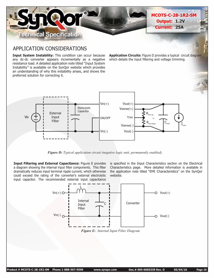
Figure D: Typical application circuit (negative logic unit, permanently enabled).
Figure E: Internal Input Filter Diagram
VinExternal Input Filter
Trim
Vin(+)
Iload
Cload
Vout(+)
Rtrim-up
or
Rtrim-down
Vsense(+)
ON/OFF
Vin(_) Vout(_)
Vsense(_)
ElectrolyticCapacitor
Input System Instability: This condition can occur because any dc-dc converter appears incrementally as a negative resistance load. A detailed application note titled “Input System Instability” is available on the SynQor website which provides an understanding of why this instability arises, and shows the preferred solution for correcting it.
Application Circuits: Figure D provides a typical circuit diagram which details the input filtering and voltage trimming.
Input Filtering and External Capacitance: Figure E provides a diagram showing the internal input filter components. This filter dramatically reduces input terminal ripple current, which otherwise could exceed the rating of the converter's external electrolytic input capacitor. The recommended external input capacitance
is specified in the Input Characteristics section on the Electrical Characteristics page. More detailed information is available in the application note titled “EMI Characteristics” on the SynQor website.
LVin(+)
Vin(_)
C
Vout(+)
Vout(-)
InternalInputFilter
Converter
Technical Specification
Product # MCOTS-C-28-1R2-SM Phone 1-888-567-9596 www.synqor.com Doc.# 005-0005339 Rev. D 05/04/10 Page 11
MCOTS-C-28-1R2-SMOutput: 1.2V
Current: 25A
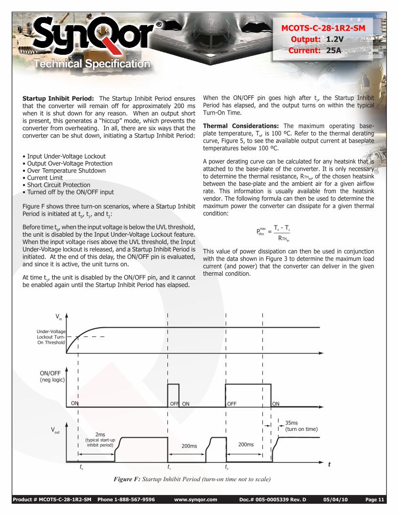
Figure F: Startup Inhibit Period (turn-on time not to scale)
Under-Voltage Lockout Turn-On Threshold
ON/OFF (neg logic)
Vout
Vin
200ms 200ms
2ms(typical start-up inhibit period)
t0 t1 t2 t
ON ON ONOFF OFF
35ms(turn on time)
Startup Inhibit Period: The Startup Inhibit Period ensures that the converter will remain off for approximately 200 ms when it is shut down for any reason. When an output short is present, this generates a “hiccup” mode, which prevents the converter from overheating. In all, there are six ways that the converter can be shut down, initiating a Startup Inhibit Period:
• Input Under-Voltage Lockout• Output Over-Voltage Protection• Over Temperature Shutdown• Current Limit• Short Circuit Protection• Turned off by the ON/OFF input
Figure F shows three turn-on scenarios, where a Startup Inhibit Period is initiated at t0, t1, and t2:
Before time t0, when the input voltage is below the UVL threshold, the unit is disabled by the Input Under-Voltage Lockout feature. When the input voltage rises above the UVL threshold, the Input Under-Voltage lockout is released, and a Startup Inhibit Period is initiated. At the end of this delay, the ON/OFF pin is evaluated, and since it is active, the unit turns on.
At time t1, the unit is disabled by the ON/OFF pin, and it cannot be enabled again until the Startup Inhibit Period has elapsed.
When the ON/OFF pin goes high after t2, the Startup Inhibit Period has elapsed, and the output turns on within the typical Turn-On Time.
Thermal Considerations: The maximum operating base-plate temperature, TB, is 100 ºC. Refer to the thermal derating curve, Figure 5, to see the available output current at baseplate temperatures below 100 ºC.
A power derating curve can be calculated for any heatsink that is attached to the base-plate of the converter. It is only necessary to determine the thermal resistance, RTHBA, of the chosen heatsink between the base-plate and the ambient air for a given airflow rate. This information is usually available from the heatsink vendor. The following formula can then be used to determine the maximum power the converter can dissipate for a given thermal condition:
Pmax
= TB - TA
diss
RTHBA
This value of power dissipation can then be used in conjunction with the data shown in Figure 3 to determine the maximum load current (and power) that the converter can deliver in the given thermal condition.
Technical Specification
Product # MCOTS-C-28-1R2-SM Phone 1-888-567-9596 www.synqor.com Doc.# 005-0005339 Rev. D 05/04/10 Page 12
MCOTS-C-28-1R2-SMOutput: 1.2V
Current: 25A
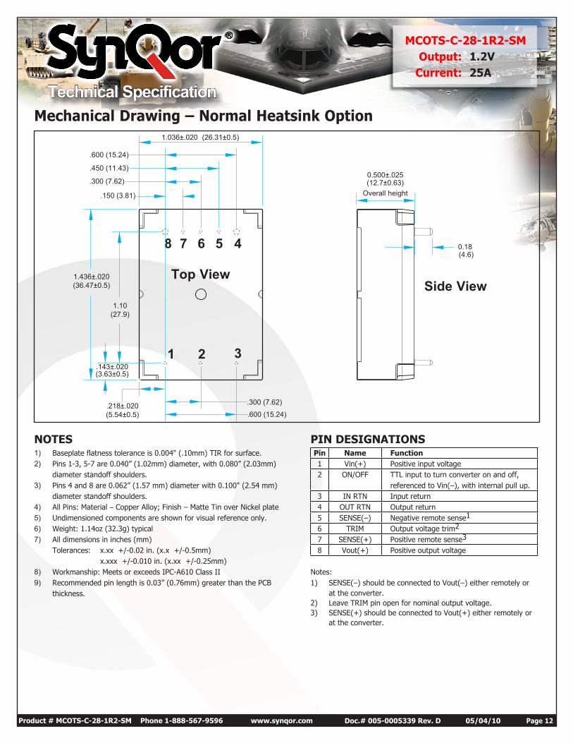
Mechanical Drawing – Normal Heatsink Option
NOTES1) Baseplate flatness tolerance is 0.004" (.10mm) TIR for surface.2) Pins 1-3, 5-7 are 0.040” (1.02mm) diameter, with 0.080” (2.03mm)
diameter standoff shoulders.3) Pins 4 and 8 are 0.062” (1.57 mm) diameter with 0.100" (2.54 mm)
diameter standoff shoulders.4) All Pins: Material – Copper Alloy; Finish – Matte Tin over Nickel plate5) Undimensioned components are shown for visual reference only.6) Weight: 1.14oz (32.3g) typical7) All dimensions in inches (mm)
Tolerances: x.xx +/-0.02 in. (x.x +/-0.5mm) x.xxx +/-0.010 in. (x.xx +/-0.25mm)
8) Workmanship: Meets or exceeds IPC-A610 Class II9) Recommended pin length is 0.03” (0.76mm) greater than the PCB
thickness.
PIN DESIGNATIONSPin Name Function1 Vin(+) Positive input voltage2 ON/OFF TTL input to turn converter on and off,
referenced to Vin(–), with internal pull up.3 IN RTN Input return4 OUT RTN Output return5 SENSE(–) Negative remote sense1
6 TRIM Output voltage trim2
7 SENSE(+) Positive remote sense3
8 Vout(+) Positive output voltage
Notes:1) SENSE(–) should be connected to Vout(–) either remotely or
at the converter.2) Leave TRIM pin open for nominal output voltage.3) SENSE(+) should be connected to Vout(+) either remotely or
at the converter.
1.036±.020 (26.31±0.5)
.150 (3.81)
.600 (15.24)
.450 (11.43)
.300 (7.62)
.600 (15.24)
.300 (7.62).218±.020(5.54±0.5)
Overall height
0.500±.025(12.7±0.63)
Side View
0.18(4.6)
.143±.020(3.63±0.5)
1.436±.020(36.47±0.5)
1.10(27.9)
Top View
45678
1 2 3
Technical Specification
Product # MCOTS-C-28-1R2-SM Phone 1-888-567-9596 www.synqor.com Doc.# 005-0005339 Rev. D 05/04/10 Page 13
MCOTS-C-28-1R2-SMOutput: 1.2V
Current: 25A
.017 .020[ 0,43 0,5 ]
.21[ 5,3 ]
.94[ 23,9 ]
.14 [ 3,6 ]
.218 .020 [ 5,54 0,5 ]
.350 .020 [ 8,89 0,5 ]
.450 .020 [ 11,43 0,5 ]
]
1.12[ 28,3 ]
1.436[ 36,47 ]
.13 [ 3,2 ]BOTTOMSIDECLEARANCE.010 [ 0,25 ]
.300 [ 7,62 ]
.600 [ 15,24 ]
TOP VIEW
1123
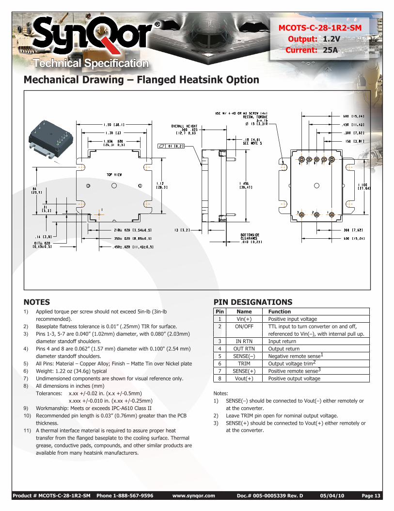
Mechanical Drawing – Flanged Heatsink Option
NOTES1) Applied torque per screw should not exceed 5in-lb (3in-lb
recommended).2) Baseplate flatness tolerance is 0.01” (.25mm) TIR for surface.3) Pins 1-3, 5-7 are 0.040” (1.02mm) diameter, with 0.080” (2.03mm)
diameter standoff shoulders.4) Pins 4 and 8 are 0.062” (1.57 mm) diameter with 0.100" (2.54 mm)
diameter standoff shoulders.5) All Pins: Material – Copper Alloy; Finish – Matte Tin over Nickel plate6) Weight: 1.22 oz (34.6g) typical7) Undimensioned components are shown for visual reference only.8) All dimensions in inches (mm)
Tolerances: x.xx +/-0.02 in. (x.x +/-0.5mm)x.xxx +/-0.010 in. (x.xx +/-0.25mm)
9) Workmanship: Meets or exceeds IPC-A610 Class II10) Recommended pin length is 0.03” (0.76mm) greater than the PCB
thickness.11) A thermal interface material is required to assure proper heat
transfer from the flanged baseplate to the cooling surface. Thermalgrease, conductive pads, compounds, and other similar products areavailable from many heatsink manufacturers.
PIN DESIGNATIONSPin Name Function1 Vin(+) Positive input voltage2 ON/OFF TTL input to turn converter on and off,
referenced to Vin(–), with internal pull up.3 IN RTN Input return4 OUT RTN Output return5 SENSE(–) Negative remote sense1
6 TRIM Output voltage trim2
7 SENSE(+) Positive remote sense3
8 Vout(+) Positive output voltage
Notes:1) SENSE(–) should be connected to Vout(–) either remotely or
at the converter.2) Leave TRIM pin open for nominal output voltage.3) SENSE(+) should be connected to Vout(+) either remotely or
at the converter.
Technical Specification
Product # MCOTS-C-28-1R2-SM Phone 1-888-567-9596 www.synqor.com Doc.# 005-0005339 Rev. D 05/04/10 Page 14
MCOTS-C-28-1R2-SMOutput: 1.2V
Current: 25A
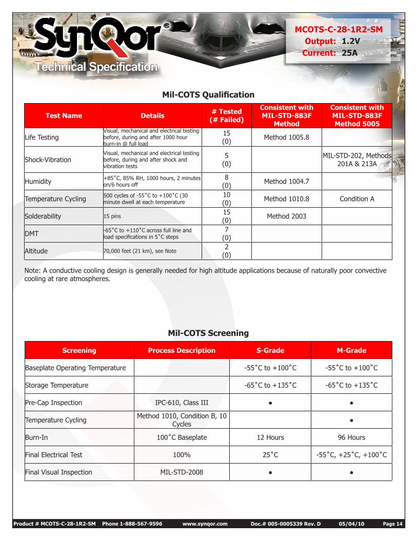
Mil-COTS Screening
Screening Process Description S-Grade M-Grade
Baseplate Operating Temperature -55˚C to +100˚C -55˚C to +100˚C
Storage Temperature -65˚C to +135˚C -65˚C to +135˚C
Pre-Cap Inspection IPC-610, Class III
Temperature Cycling Method 1010, Condition B, 10 Cycles
Burn-In 100˚C Baseplate 12 Hours 96 Hours
Final Electrical Test 100% 25˚C -55˚C, +25˚C, +100˚C
Final Visual Inspection MIL-STD-2008
Mil-COTS Qualification
Test Name Details # Tested (# Failed)
Consistent with MIL-STD-883F
Method
Consistent with MIL-STD-883F Method 5005
Life TestingVisual, mechanical and electrical testing before, during and after 1000 hour burn-in @ full load
15 (0) Method 1005.8
Shock-VibrationVisual, mechanical and electrical testing before, during and after shock and vibration tests
5 (0)
MIL-STD-202, Methods 201A & 213A
Humidity +85˚C, 85% RH, 1000 hours, 2 minutes on/6 hours off
8 (0) Method 1004.7
Temperature Cycling 500 cycles of -55˚C to +100˚C (30 minute dwell at each temperature
10 (0) Method 1010.8 Condition A
Solderability 15 pins15 (0) Method 2003
DMT -65˚C to +110˚C across full line and load specifications in 5˚C steps
7 (0)
Altitude 70,000 feet (21 km), see Note2
(0)
Note: A conductive cooling design is generally needed for high altitude applications because of naturally poor convective cooling at rare atmospheres.
Technical Specification
Product # MCOTS-C-28-1R2-SM Phone 1-888-567-9596 www.synqor.com Doc.# 005-0005339 Rev. D 05/04/10 Page 15
MCOTS-C-28-1R2-SMOutput: 1.2V
Current: 25A
WarrantySynQor offers a two (2) year limited warranty. Complete warranty information is listed on our website or is available upon request from SynQor.
Information furnished by SynQor is believed to be accurate and reliable. However, no responsibility is assumed by SynQor for its use, nor for any infringements of patents or other rights of third parties which may result from its use. No license is granted by implication or otherwise under any patent or patent rights of SynQor.
Contact SynQor for further information:
Phone: 978-849-0600 Toll Free: 888-567-9596 Fax: 978-849-0602 E-mail: [email protected] Web: www.synqor.com Address: 155 Swanson Road Boxborough, MA 01719 USA
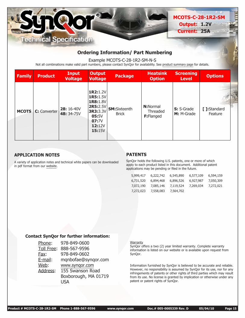
Example MCOTS-C-28-1R2-SM-N-SNot all combinations make valid part numbers, please contact SynQor for availability. See product summary page for details.
APPLICATION NOTESA variety of application notes and technical white papers can be downloaded in pdf format from our website.
Ordering Information/ Part Numbering
PATENTS SynQor holds the following U.S. patents, one or more of which apply to each product listed in this document. Additional patent applications may be pending or filed in the future.
5,999,417 6,222,742 6,545,890 6,577,109 6,594,159
6,731,520 6,894,468 6,896,526 6,927,987 7,050,309
7,072,190 7,085,146 7,119,524 7,269,034 7,272,021
7,272,023 7,558,083 7,564,702
Family Product Input Voltage
Output Voltage Package Heatsink
OptionScreening
Level Options
MCOTS C: Converter 28: 16-40V 48: 34-75V
1R2: 1R5: 1R8: 2R5: 3R3:
05: 07: 12: 15:
1.2V 1.5V 1.8V 2.5V 3.3V 5V 7V 12V 15V
SM: Sixteenth Brick
N:
F:
Normal Threaded Flanged
S: S-Grade M: M-Grade
[ ]: Standard Feature