Embed Size (px)
Citation preview
Page | 1
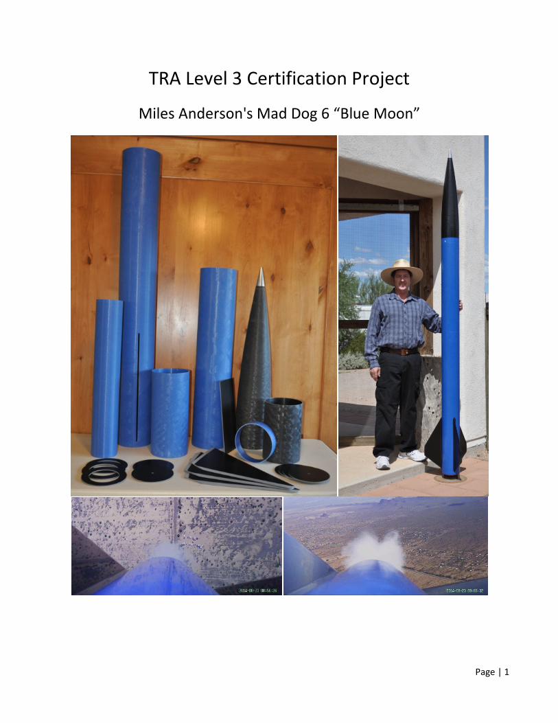
TRA Level 3 Certification Project
Miles Anderson's Mad Dog 6 “Blue Moon”
Page | 2
Table of Contents
Background 3
Choosing a Level 3 Rocket Design 3
Basic Design 3
Preparation for Epoxy 4
Nose Cone Modification 4
Avionics Bay 5
Securing the Upper Body Tube to the Avionics Bay 9
Coupler 9
Motor Mount 10
Fin Attachment 11
Thrust Plate, Motor Retainer, and Rail Buttons 13
External Fin Fillets 14
Sheer Pins 14
Vent Holes 15
Recovery 15
Calculating BP Charges and Ground Testing 16
Finishing the Airframe 17
Test Flight 18
Certification Flight Simulation 21
Parts List 23
Pre-Launch and Launch Day Checklists 25
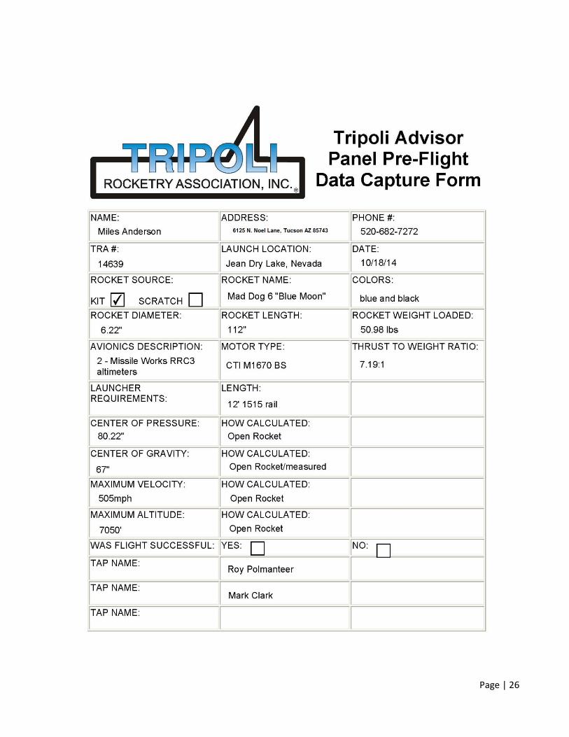
TAP Pre-Flight Data Capture Form 26
Page | 3
Background
Like so many of my cohort currently in the hobby, I flew low-powered model rockets in my youth and still have a handful of them from early 1970s Estes and Centuri kits. I started flying low-powered rockets again on our property about two years ago. This involved a kind of desert parkour – tracking the rocket while running and jumping over cholla and prickly pear cacti. I was blissfully unaware that the Southern Arizona Rocketry Association had held monthly launches 15 minutes from our home for the past 18 years. I purchased my first high-powered kit in March 2013 and got my Level 1 Certification at the next launch.
Choosing a Level 3 Rocket Design
My Level 1 rocket was a Polecat Aerospace Spike, a ring-fin design. Level 2 was the Tubula Rasa, a scratch built, 4" blue tube/7' tall dual deploy rocket with three tube fins. My quota for whimsical certification rockets having been filled, my choice for a Level 3 rocket needed to be robust, durable, and with the potential of surviving supersonic flight. The Mad Dog 6 sold by Rocketry Warehouse met those requirements with the added bonus of being made of colored fiberglass, which saved on the seven or more coats of primer and paint I typically apply to a rocket.
Basic Design
After acquiring the parts, weighing and measuring them, and building the rocket virtually in Open Rocket, I realized that the typical design (with the avionics bay as a coupler between the fin can section and upper payload bay) didn’t leave enough room in the fin can section for a parachute and a full M or small N impulse motor.
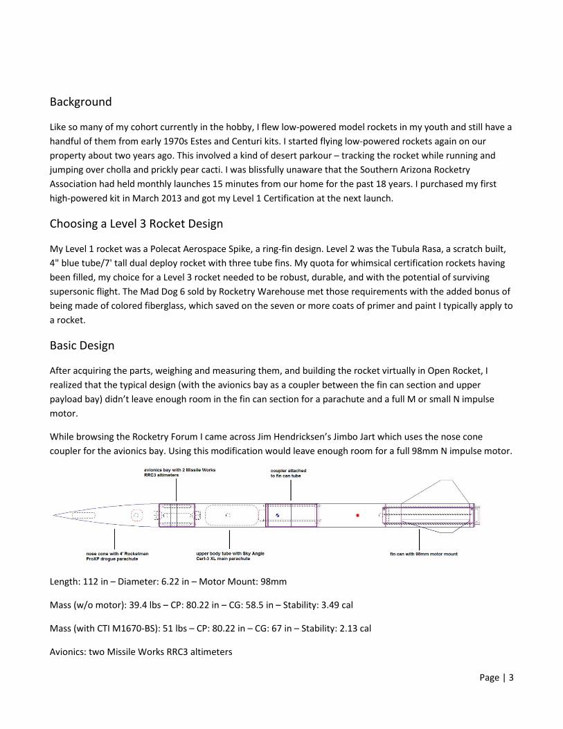
While browsing the Rocketry Forum I came across Jim Hendricksen’s Jimbo Jart which uses the nose cone coupler for the avionics bay. Using this modification would leave enough room for a full 98mm N impulse motor.
Length: 112 in – Diameter: 6.22 in – Motor Mount: 98mm
Mass (w/o motor): 39.4 lbs – CP: 80.22 in – CG: 58.5 in – Stability: 3.49 cal
Mass (with CTI M1670-BS): 51 lbs – CP: 80.22 in – CG: 67 in – Stability: 2.13 cal
Avionics: two Missile Works RRC3 altimeters
Page | 4
Preparation for Epoxy
To remove mold release and any other dirt, all fiberglass surfaces were scrubbed with Simple Green concentrate, rinsed, scrubbed with 70% isopropyl alcohol, rinsed again, and dried.
In preparation for bonding with adhesives, the portion to be bonded was sanded and cleaned with 70% isopropyl alcohol. Nitrile gloves were used to handle any prepared surfaces and anything contaminated was cleaned again with alcohol prior to bonding.
Nose Cone Modification
The nose cone from the Mad Dog 6 kit came with a removable aluminum tip. I modified this so that a weight could be added to offset the 98mm Aeropac motor retainer and 6”- 98mm SCP thrust plate at the other end of the airframe. The aluminum tip was threaded for ¼-20. I used a length of ¼-20 all-thread to hold the aluminum tip, weight, and eye nut. I took a short length of 1½” PVC pipe, glued on an end cap, and drilled a hole in the center to fit a length of ¼” brass tubing. Next, 500g of steel BBs were mixed with 30-minute epoxy and poured into the PVC pipe. After the epoxy cured, the open end was cut flat. The all-thread was left long enough so that a hole could be drilled to accept a cotter pin to keep the assembly from coming loose.

Page | 5
Avionics Bay
In order to position the altimeter switch band correctly, I needed to put the bulkheads and all-thread together first. I used all 3/8” hardware: all-thread, U-bolts, nuts, and washers.
The avionics bay was pushed into the nose cone until it stopped, then pulled back about 1/8” to mark the position of the altimeter switch band. The altimeter switch band was attached with Aeropoxy ES6209.
The equation from Vern Knowles’ web site, DN = 0.02216*DT*sqrt(L/N), was used to calculate the static port sizing. Where the diameter of the interior is 5.83”, the interior length is 9”, and the number of ports is 3:
0.02216*5.83*sqrt(9/3) = 0.2237”
Three 7/32” static port holes were drilled 120 degrees apart. Two of these are used to access the altimeter switches.
Page | 6
To make the sled, the 12”x 4-7/8”x 3/16” sheet of G10 fiberglass was cut to 7” long. Pieces of 1” angle aluminum were cut and tapped with 8-32 threads and drilled to accommodate lengths of 7/16” brass tubing.
The switch holders were made from 1½” slotted angle iron. Once they were positioned to line up with the altimeter ports, the positions were marked, drilled, and the holders were tapped with 8-32 threads.
Page | 7
To save on space the two battery holders were fitted with 4-40 pem nuts and attached to both sides of the sled in a head to tail fashion. I drilled four holes to accommodate zip ties as added insurance that the batteries would stay in place.
Once the altimeters were positioned and the holes drilled, they were mounted with 4-40 screws and nuts with 6-32 neoprene washers as the standoffs.
Each of the bulkheads was finished with:
two large Blastcaps
two terminal blocks secured with 4-40 screws and nuts
paired wires running from the inside of the avionics bay to the terminal blocks (the holes were sealed with CA)
The remainder of the wiring was installed. Wires were soldered to the battery holders. Additional wires were soldered to the switches, and the exposed metal on the switches was covered with shrink tubing.

Page | 8

Page | 9
Securing the Upper Body Tube to the Avionics Bay
I drilled three 9/64” holes through the upper body tube and into the avionics bay. They were 1½” below the top of the upper body tube, spaced 120 degrees apart, and offset 60 degrees from the static ports. Three 6-32 screws and t-nuts were screwed in place. The t-nuts were then glued to the avionics bay with CA.
Coupler
I used three lengths of 3/8” all-thread, a 3/8” U-bolt, and 3/8” washers, lock washers, and nuts. The removable bulkhead was made from two 3/16” G10 fiberglass discs and a disc of ½” plywood laminated between them with Aeropoxy ES6209.
The purpose of this design was to have a robust coupler and attachment point for the recovery harness with a removable bulkhead. This will allow access to the inside of the fin can body tube and also accommodate a full-length 98mm motor. Once the plywood rings and all-thread were assembled I bonded them in place with Aeropoxy ES6209.

Page | 10
The finished unit was then ready to be installed at the top of the fin can tube where it would be permanently bonded with Aeropoxy ES6209. (The coupler was installed after the motor tube, fins, and rail button were complete.)
Motor Mount
Page | 11
The Mad Dog 6 kit came with a 20”x 4” fiberglass motor tube and three 1/8” G10 centering rings. To this I added lengths of 10-24 all-thread, 10-24 nuts, and three 10-24 coupling nuts. The 10-24 hardware served to both align and hold the rings in place, and, together with the coupling nuts, provided points of attachment for the 6”- 98mm SCP thrust plate. Aeropoxy ES6209 was used to join the centering rings to the motor and body tubes.
Fin Attachment
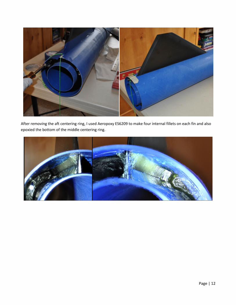
In order to make the internal fillets without injecting epoxy through the body tube, the aft centering ring was left free. I secured the body tube to a table and used a plumb line to position a fin slot at the top of the tube. A generous bead of Aeropoxy ES6209 was applied to the root of the fin and the fin was inserted into the body tube. I did this two more times to ensure enough epoxy was present to form a complete bond at the root of the fin. I then used a level to position the fin perpendicular to the body tube. Tightening the coupling nuts against the aft centering ring locked the fin in position and the epoxy was allowed to cure. This was repeated for the remaining two fins.
Page | 12
After removing the aft centering ring, I used Aeropoxy ES6209 to make four internal fillets on each fin and also epoxied the bottom of the middle centering ring.

Page | 13
Thrust Plate, Motor Retainer, and Rail Buttons
The aft centering ring could now be Aeropoxied in place. On a line halfway between the fins I drilled 5/32” holes at ½” and 30¼” (the center of pressure) from the aft end of the fin can tube. Inside the tube 10-24 t-nuts were glued in place with CA to anchor the 1515 rail buttons. The Aeropac 98mm motor retainer was screwed to the thrust plate and that assembly was screwed to the 10-24 coupling nuts.
Page | 14
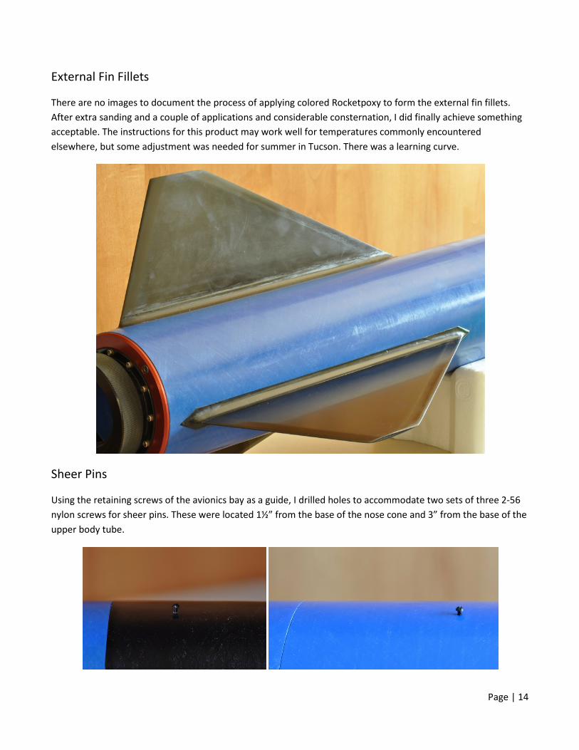
External Fin Fillets
There are no images to document the process of applying colored Rocketpoxy to form the external fin fillets. After extra sanding and a couple of applications and considerable consternation, I did finally achieve something acceptable. The instructions for this product may work well for temperatures commonly encountered elsewhere, but some adjustment was needed for summer in Tucson. There was a learning curve.
Sheer Pins
Using the retaining screws of the avionics bay as a guide, I drilled holes to accommodate two sets of three 2-56 nylon screws for sheer pins. These were located 1½” from the base of the nose cone and 3” from the base of the upper body tube.
Page | 15
Vent Holes
I drilled a 3/16” hole in the nose cone (above the avionics bay), in the upper body tube (below the avionics bay), and in the fin can tube.
Recovery
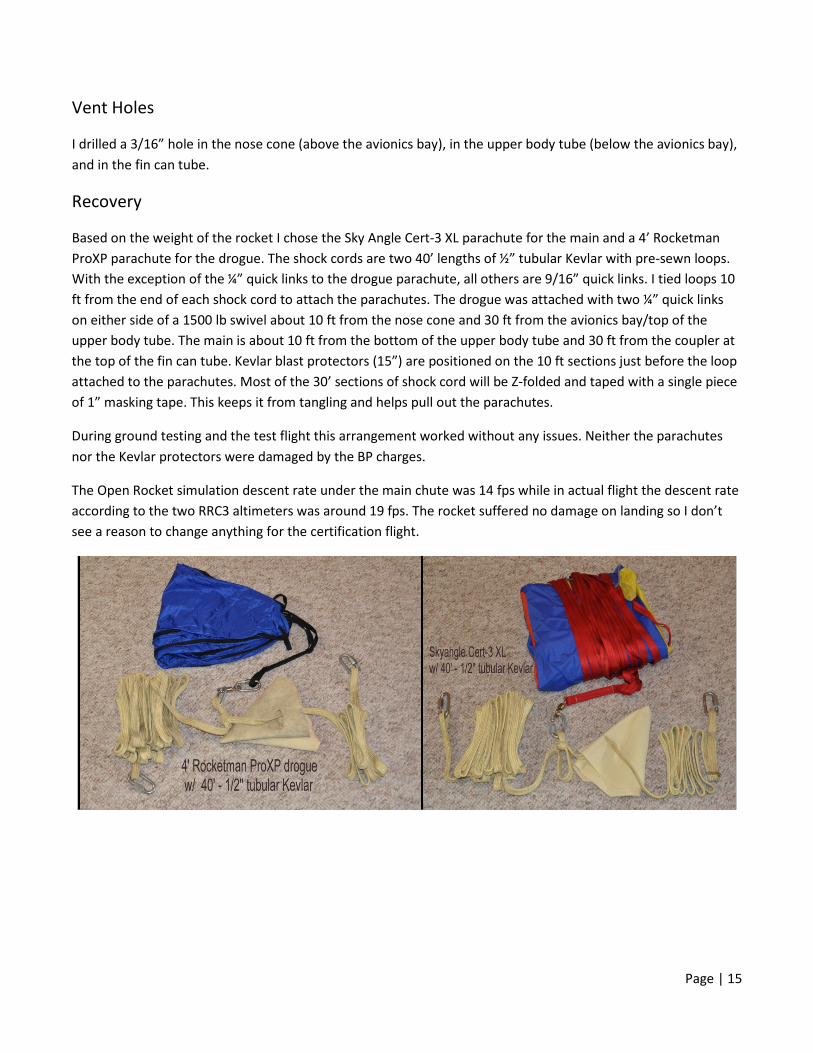
Based on the weight of the rocket I chose the Sky Angle Cert-3 XL parachute for the main and a 4’ Rocketman ProXP parachute for the drogue. The shock cords are two 40’ lengths of ½” tubular Kevlar with pre-sewn loops. With the exception of the ¼” quick links to the drogue parachute, all others are 9/16” quick links. I tied loops 10 ft from the end of each shock cord to attach the parachutes. The drogue was attached with two ¼” quick links on either side of a 1500 lb swivel about 10 ft from the nose cone and 30 ft from the avionics bay/top of the upper body tube. The main is about 10 ft from the bottom of the upper body tube and 30 ft from the coupler at the top of the fin can tube. Kevlar blast protectors (15”) are positioned on the 10 ft sections just before the loop attached to the parachutes. Most of the 30’ sections of shock cord will be Z-folded and taped with a single piece of 1” masking tape. This keeps it from tangling and helps pull out the parachutes.
During ground testing and the test flight this arrangement worked without any issues. Neither the parachutes nor the Kevlar protectors were damaged by the BP charges.
The Open Rocket simulation descent rate under the main chute was 14 fps while in actual flight the descent rate according to the two RRC3 altimeters was around 19 fps. The rocket suffered no damage on landing so I don’t see a reason to change anything for the certification flight.
Page | 16
Calculating BP Charges and Ground Testing
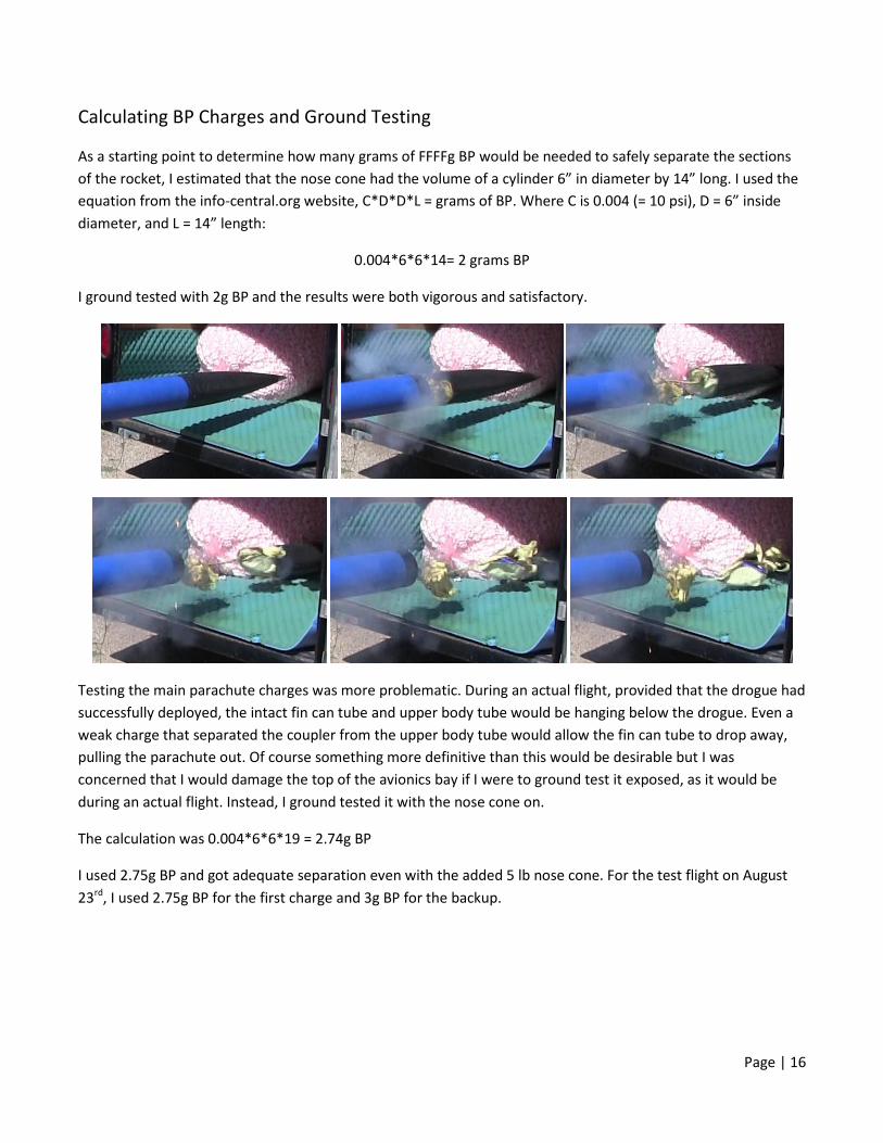
As a starting point to determine how many grams of FFFFg BP would be needed to safely separate the sections of the rocket, I estimated that the nose cone had the volume of a cylinder 6” in diameter by 14” long. I used the equation from the info-central.org website, C*D*D*L = grams of BP. Where C is 0.004 (= 10 psi), D = 6” inside diameter, and L = 14” length:
0.004*6*6*14= 2 grams BP
I ground tested with 2g BP and the results were both vigorous and satisfactory.
Testing the main parachute charges was more problematic. During an actual flight, provided that the drogue had successfully deployed, the intact fin can tube and upper body tube would be hanging below the drogue. Even a weak charge that separated the coupler from the upper body tube would allow the fin can tube to drop away, pulling the parachute out. Of course something more definitive than this would be desirable but I was concerned that I would damage the top of the avionics bay if I were to ground test it exposed, as it would be during an actual flight. Instead, I ground tested it with the nose cone on.
The calculation was 0.004*6*6*19 = 2.74g BP
I used 2.75g BP and got adequate separation even with the added 5 lb nose cone. For the test flight on August 23rd, I used 2.75g BP for the first charge and 3g BP for the backup.
Page | 17
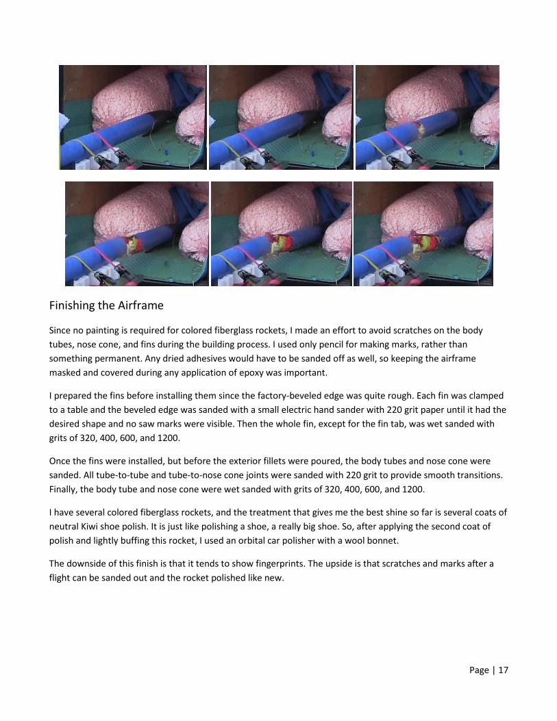
Finishing the Airframe
Since no painting is required for colored fiberglass rockets, I made an effort to avoid scratches on the body tubes, nose cone, and fins during the building process. I used only pencil for making marks, rather than something permanent. Any dried adhesives would have to be sanded off as well, so keeping the airframe masked and covered during any application of epoxy was important.
I prepared the fins before installing them since the factory-beveled edge was quite rough. Each fin was clamped to a table and the beveled edge was sanded with a small electric hand sander with 220 grit paper until it had the desired shape and no saw marks were visible. Then the whole fin, except for the fin tab, was wet sanded with grits of 320, 400, 600, and 1200.
Once the fins were installed, but before the exterior fillets were poured, the body tubes and nose cone were sanded. All tube-to-tube and tube-to-nose cone joints were sanded with 220 grit to provide smooth transitions. Finally, the body tube and nose cone were wet sanded with grits of 320, 400, 600, and 1200.
I have several colored fiberglass rockets, and the treatment that gives me the best shine so far is several coats of neutral Kiwi shoe polish. It is just like polishing a shoe, a really big shoe. So, after applying the second coat of polish and lightly buffing this rocket, I used an orbital car polisher with a wool bonnet.
The downside of this finish is that it tends to show fingerprints. The upside is that scratches and marks after a flight can be sanded out and the rocket polished like new.
Page | 18
Test Flight
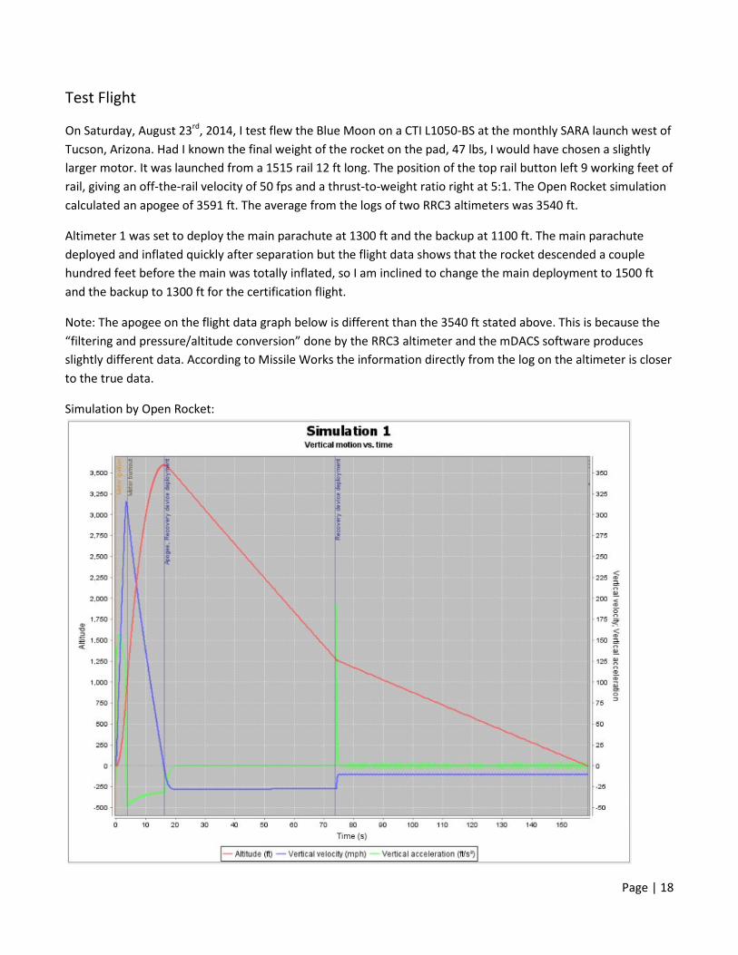
On Saturday, August 23rd, 2014, I test flew the Blue Moon on a CTI L1050-BS at the monthly SARA launch west of Tucson, Arizona. Had I known the final weight of the rocket on the pad, 47 lbs, I would have chosen a slightly larger motor. It was launched from a 1515 rail 12 ft long. The position of the top rail button left 9 working feet of rail, giving an off-the-rail velocity of 50 fps and a thrust-to-weight ratio right at 5:1. The Open Rocket simulation calculated an apogee of 3591 ft. The average from the logs of two RRC3 altimeters was 3540 ft.
Altimeter 1 was set to deploy the main parachute at 1300 ft and the backup at 1100 ft. The main parachute deployed and inflated quickly after separation but the flight data shows that the rocket descended a couple hundred feet before the main was totally inflated, so I am inclined to change the main deployment to 1500 ft and the backup to 1300 ft for the certification flight.
Note: The apogee on the flight data graph below is different than the 3540 ft stated above. This is because the “filtering and pressure/altitude conversion” done by the RRC3 altimeter and the mDACS software produces slightly different data. According to Missile Works the information directly from the log on the altimeter is closer to the true data.
Simulation by Open Rocket:

Page | 19
Flight log by RRC3 altimeter uploads by mDACS software:

Page | 20
Launch pictures by Stephen Fraser
Page | 21
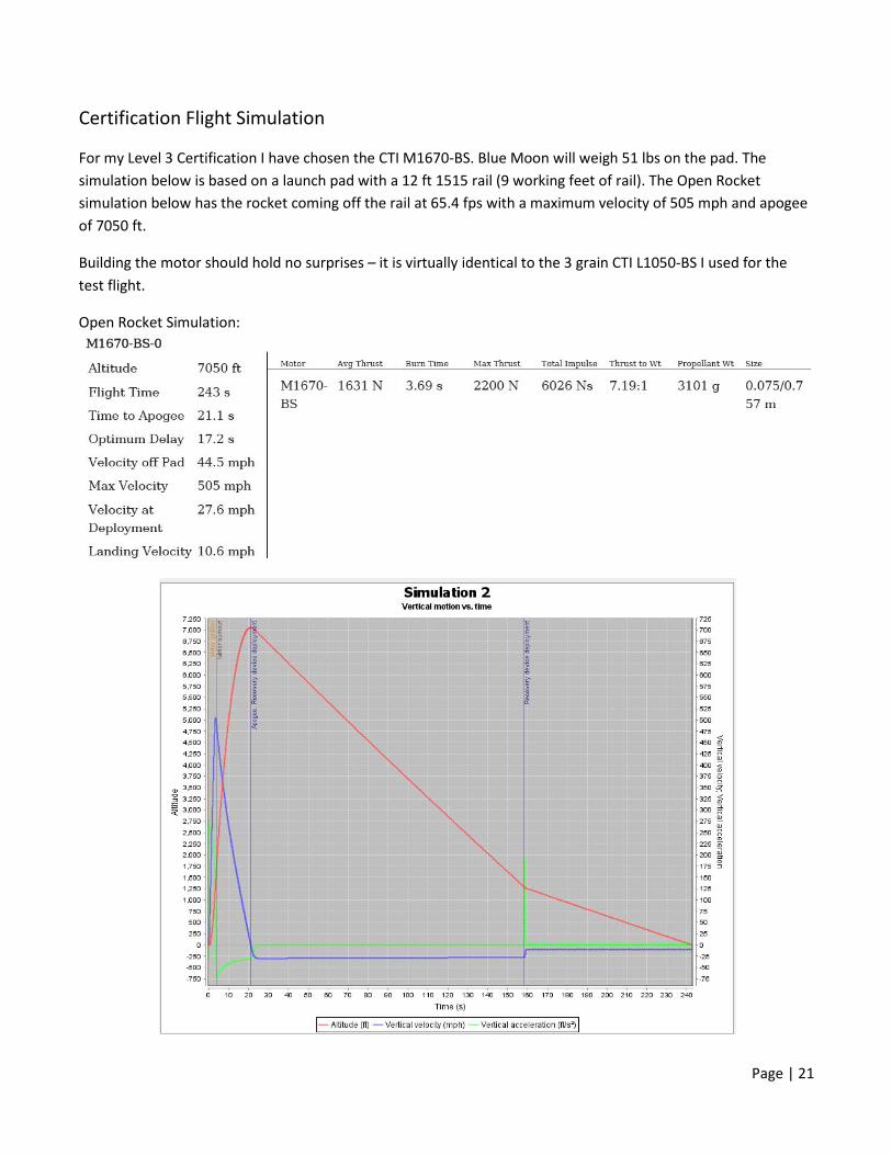
Certification Flight Simulation
For my Level 3 Certification I have chosen the CTI M1670-BS. Blue Moon will weigh 51 lbs on the pad. The simulation below is based on a launch pad with a 12 ft 1515 rail (9 working feet of rail). The Open Rocket simulation below has the rocket coming off the rail at 65.4 fps with a maximum velocity of 505 mph and apogee of 7050 ft.
Building the motor should hold no surprises – it is virtually identical to the 3 grain CTI L1050-BS I used for the test flight.
Open Rocket Simulation:

Page | 22
Thrust curve provided by CTI:

Page | 23
Parts List
Nose Cone: aluminum-tipped black fiberglass nose cone – 30.9 in x 6.22 in ~5 in length of 1½” PVC pipe 1½” PVC end cap ~5 in length ¼” brass tube ¼-20 all-thread ¼” nuts and washers 500 lb ¼-20 eye nut cotter pin 500g BBs 30-minute epoxy Avionics Bay:
black fiberglass tube – 9.29 in x 6.06 in blue fiberglass altimeter switch band – 1.67 in x 6.22 in two black fiberglass bulkheads – 0.118 in x 6.06 in two black fiberglass bulkheads – 0.118 in x 5.83 in sheet of G10 fiberglass – 12”x 4-7/8”x 3/16” two lengths of 1” angle aluminum eight 8-32 screws two lengths of 7/16” brass tube two lengths of 3/8-16 all-thread two rotary switches two Missile Works RRC3 altimeters eight neoprene washers sixteen 4-40 screws twelve 4-40 nuts four 4-40 pem nuts two battery holders two 3/8” x 2” U-bolts eighteen 3/8” nuts fourteen 3/8” washers four terminal blocks four Blastcaps, large three 6-32 screws and t-nuts Aeropoxy ES6209
Blue Fiberglass Upper Body Tube – 30 in x 6.22 in

Page | 24
Coupler: blue fiberglass tube – 13.34 in x 6.06 in black fiberglass bulkhead – 0.118 in x 6.06 in black fiberglass bulkhead – 0.118 in x 5.83 in plywood bulkhead – 0.47 in x 5.83 in two plywood rings – 0.47 in x 5.75 in OD/4.15 in ID plywood ring – 0.47 in x 6.06 in OD/4.15 in ID 3/8” x 3” U-bolt three lengths 3/8” all-thread nineteen 3/8” nuts and washers Aeropoxy ES6209
Fin Can Body Tube and Motor Mount: pre-slotted blue fiberglass tube – 48.2 in x 6.22 in three black fiberglass fins
blue fiberglass tube – 24 in x 4 in three black fiberglass centering rings – 0.12 in x 5.98 in OD/4.01 in ID three lengths 10-24 all-thread twelve 10-24 nuts three 10-24 coupling nuts Aeropac 98mm motor retainer SCP thrust plate 6”- 98mm two 10-24 t-nuts and screws two 1515 Delrin rail buttons three 10-24 screws

Page | 25
Checklist in Advance of Launch Day
1. Tighten all fittings, including: a. Screws and nuts associated with avionics bay. b. Coupling nuts, thrust plate screws, motor retainer screws. c. Nuts associated with removable bulkhead on coupler. d. Removable weight in nose cone
2. Using Missile Work LCD, check altimeters to verifiy altitudes for drogue parachute and main parachute deployment, arming altitude, and battery charge.
3. Close avionics bay, align switches with static ports, and tighten nuts. 4. Install e-matches to terminal blocks, tape in place to Blastcaps, and test for continuity with
altimeters. After continuity is verified, switch off altimeters, unscrew e-matches from terminal blocks and twist e-match ends together to prevent ignition from static charges.
5. Load Blastcaps with correct BP charges and dog barf. Mask top of Blastcaps. 6. Assemble recovery system and tighten quick links with pliers. 7. Fold and pack drogue and main parachutes. 8. Assemble motor as per included instructions. 9. Load motor into motor tube and measure rocket for actual weight and center of gravity. 10. Remove and store assembled motor.
Checklist for Launch Day
1. Verify waiver altitude with local club and determine if call-in window will be necessary. 2. Access ends of avoinics bay and install e-match wires. 3. Reinstall avionics bay in upper body tube and fasten with screws. 4. Verify that parachutes are still folded correctly, shielded by the Kevlar blast protector, and that the
recovery harnesses are in the correct position . 5. Install sheer pins to nose cone and upper body tube. 6. Tape camera to fin can tube of rocket. 7. Contact TAP to inspect the rocket and verify that all paperwork is correct. 8. Take flight card and other necessary paperwork and rocket for inspection by RSO. 9. Once assigned a pad, take the rocket and a ladder (if one is not already there) to the pad. 10. Install rocket on the rail and raise to 5 degrees from vertical away from the crowd. 11. Arm both altimeters and verify that they are functioning correctly. 12. Install igniter in motor. 13. Turn on camera. 14. Once back at the launch line, make sure camera(s) are ready.
Page | 26