Embed Size (px)
Citation preview
Milestone 5 Final Report: Hybrid Lyot and Shaped Pupil BroadbandContrast Testbed Demonstration for WFIRST-AFTA
Eric Cadya, Byoung-Joon Seoa, Bala Balasubramaniana, Frank Greera, Brian Gordona, N.Jeremy Kasdinb, Brian Kerna, Andy Kuhnerta, David Marxa, Camilo Mejia Pradaa,Dwight Moodya, Richard Mullera, Ilya Poberezhskiya, A.J. Riggsb, John Traugera, DanielWilsona, Victor Whitea, Karl Yeea, Neil Zimmermanc, and Hanying Zhouaa Jet Propulsion Laboratory, California Institute of Technology, Pasadena, CA. 91109
b Princeton University, Princeton, NJ 08544c Space Telescope Science Institute, Baltimore, MD 21218
Contents
1 Overview 2
2 Technical Background 2
3 Testbed Configuration, Operation, and Algorithm 33.1 Configuration update in Shape Pupil Coronagraph (SPC) testbed . . . . . . . . . . 33.2 Configuration update in Hybrid Lyot Coronagraph (HLC) testbed . . . . . . . . . . 43.3 Configuration update in both testbeds . . . . . . . . . . . . . . . . . . . . . . . . 5
4 Data and analysis 64.1 SPC Result . . . . . . . . . . . . . . . . . . . . . . . . . . . . . . . . . . . . . . 64.2 HLC Result . . . . . . . . . . . . . . . . . . . . . . . . . . . . . . . . . . . . . . 6
5 Conclusion and Future Work 9
6 Acronyms 9
Copyright 2015. All rights reserved.
December 31, 2015 Milestone 5 Final Report.
1 Overview
As laid out in original definitions to National Aeronautics and Space Administration (NASA)Headquarters and the Technical Analysis Committee (TAC), WFIRST-AFTA Coronagraphic In-strument (CGI) Milestone 5 was defined as:
The Occulting Mask Coronagraph (OMC) — Hybrid Lyot Coronagraph (HLC) orShape Pupil Coronagraph (SPC) —in the High Constrast Imaging Testbed (HCIT)demonstrates 10−8 raw contrast with broadband light (10%) at 550 nm in a staticenvironment.
In this report, we will present repeated convergence below 9× 10⁻⁹ mean contrast in the HCITachieved by both HLC and SPC modes of the OMC, across a 3λ/D and 9λ/D dark hole in 10%broadband light centered at 550 nm. These results were presented to the TAC on September 29th,2015, concurrently with the results of WFIRST-AFTA CGI Milestone 6.
This report is structured as follows. Sec. 2 will briefly overview the technical backgroundbehind the SPC and HLC and provide the appropriate references. In Sec. 3, we highlight the con-figuration changes made for Milestone 5 from the previous milestones, since most of the testbedconfiguration has been covered already in previous milestone reports1, 2 and in peer-reviewed pub-lications.3–5 Data and analysis, including the contrast results, are presented in Sec. 4, while con-clusions and future work are described in Sec. 5.
2 Technical Background
As the light from the WFIRST-AFTA telescope is delivered to the coronagraph instrument, the firstpupil is formed at the Fast Steering Mirror (FSM) that corrects the Line of Sight (LoS) pointingjitter and drift using information from the Low Order Wavefront Sensing and Control (LOWFS/C)subsystem. The light is then delivered to two Deformable Mirrors (DMs), which perform activewavefront control to compensate for phase and amplitude imperfections in the optical train.
SPC and HLC are the two interchangeable coronagraph modes of the OMC operation. Shapedpupil masks use optimization to design a binary-valued pupil stop whose Point Spread Function(PSF) has regions of very high contrast; an occulting focal-plane mask then blocks the entirety ofthe PSF except these “dark holes”. A coronagraph of this type was used for WFIRST-AFTA CGIMilestone 2; see [6] for more details of the design process and [3] for Milestone 2 configuration.
Hybrid Lyot Coronagraphs (HLCs), on the other hand, do not require a pupil stop; they use ajoint optimization between the settings of two DMs, the complex transmission profile of a focal-plane mask, and the shape of a following Lyot stop to produce an intricate DM initial conditionwhich provides broadband wavefront control and minimizes the effect of jitter. See [5,7] for moredetails of the HLC design process.
Page 2
December 31, 2015 Milestone 5 Final Report3 Testbed Configuration, Operation, and Algorithm
Although SPC and HLC are planned to operate in a single testbed for Milestone 9, two separatetestbeds were used for Milestone 5. The two testbeds used for SPC and HLC are essentially thesame ones as used for Milestone 2 and 4, respectively. The Milestone 2 and 4 were intended for thenarrowband contrast demonstration while Milestone 5 is for the broadband contrast demonstration.The majority of testbed configuration was retained, but several modification were necessary.
In this section, we hightlight crucial testbed modifications made for Milestone 5.
3.1 Configuration update in SPC testbed
Following testbed modificaitons have been made for Milestone 5 from Milestone 2 in SPC.
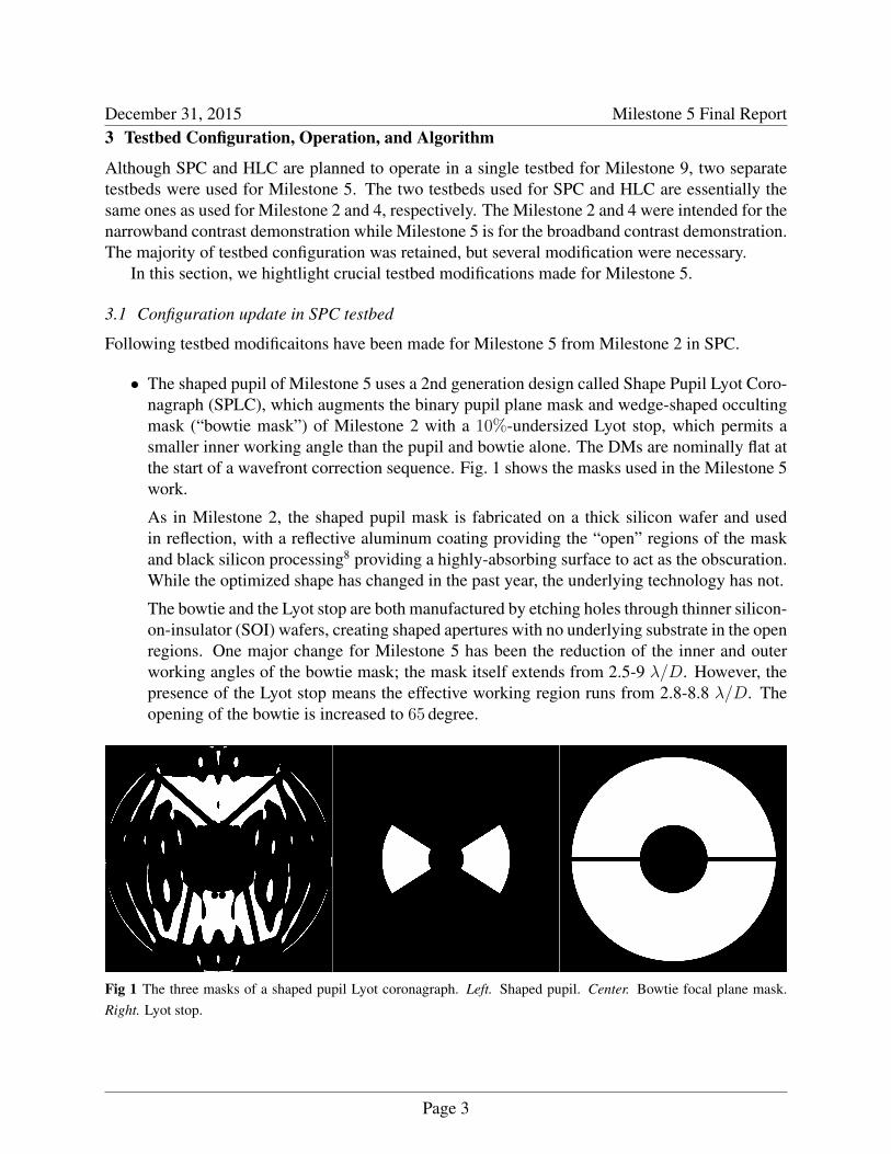
• The shaped pupil of Milestone 5 uses a 2nd generation design called Shape Pupil Lyot Coro-nagraph (SPLC), which augments the binary pupil plane mask and wedge-shaped occultingmask (“bowtie mask”) of Milestone 2 with a 10%-undersized Lyot stop, which permits asmaller inner working angle than the pupil and bowtie alone. The DMs are nominally flat atthe start of a wavefront correction sequence. Fig. 1 shows the masks used in the Milestone 5work.
As in Milestone 2, the shaped pupil mask is fabricated on a thick silicon wafer and usedin reflection, with a reflective aluminum coating providing the “open” regions of the maskand black silicon processing8 providing a highly-absorbing surface to act as the obscuration.While the optimized shape has changed in the past year, the underlying technology has not.
The bowtie and the Lyot stop are both manufactured by etching holes through thinner silicon-on-insulator (SOI) wafers, creating shaped apertures with no underlying substrate in the openregions. One major change for Milestone 5 has been the reduction of the inner and outerworking angles of the bowtie mask; the mask itself extends from 2.5-9 λ/D. However, thepresence of the Lyot stop means the effective working region runs from 2.8-8.8 λ/D. Theopening of the bowtie is increased to 65 degree.
Fig 1 The three masks of a shaped pupil Lyot coronagraph. Left. Shaped pupil. Center. Bowtie focal plane mask.Right. Lyot stop.
Page 3
December 31, 2015 Milestone 5 Final Report• A second DM was introduced 1m downstream of the first DM, replacing the flat that was
there previously. The introduction of a DM here had been part of the plan since the construc-tion of the testbed. The first DM is same as in Milestone 2, the 64 × 64-actuator DM nearthe pupil. The presence of a second DM permitted the correction of phase and amplitudeon both sides of the PSF simultaneously. This DM was 32 × 32, and necessitated a smallersystem pupil than the one used previously.
• The Lyot stop was inserted on a 3-axis stage in a pupil plane downstream of the fifth off-axisparabola (OAP). The original design for the testbed had not included a Lyot stop, and the fitturned out to be rather tight, but achievable.
• One software change was the introduction of a focal plane mask tracking loop, as the centra-tion requirements were tightened by the use of the bowtie as an active part of the correction,rather than just as a field stop as in Milestone 2. Pairs of speckles are created with sine waveson the DM, and sized to fall at the edge of the bowtie; the bowtie can then be adjusted in xand y to balance leakage.
3.2 Configuration update in HLC testbed
Following testbed modificaitons have been made for Milestone 5 from Milestone 4 in HLC.
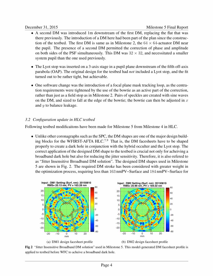
• Unlike other coronagraphs such as the SPC, the DM shapes are one of the major design build-ing blocks for the WFIRST-AFTA HLC.7, 9 That is, the DM facesheets have to be shapedproperly to create a dark hole in conjunction with the hybrid occulter and the Lyot stop. Thecorrect application of the designed DM shape to the testbed is crucial not only for acheiving abroadband dark hole but also for reducing the jitter sensitivity. Therefore, it is also refered toas “Jitter Insensitive Broadband DM solution”. The designed DM shapes used in Milestone5 are shown in Fig. 2. The required DM stroke has been considered with greater weight inthe optimization process, requiring less than 163 nmPV−Surface and 184 nmPV−Surface for
(a) DM1 design facesheet profile (b) DM2 design facesheet profileFig 2 “Jitter Insensitive Broadband DM solution” used in Milestone 5. This model-generated DM facesheet profile isapplied to testbed before WFC to acheive a broadband dark hole.
Page 4
December 31, 2015 Milestone 5 Final ReportDM1 and DM2, respectively. This represents ∼ 40% decrease compared to previous HLCdesign iterations and is a positive developement as it increases the DM stroke range margin.
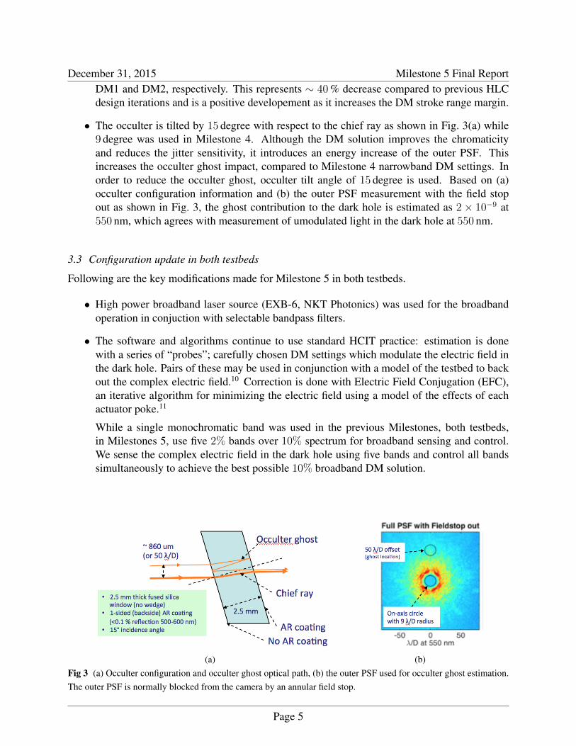
• The occulter is tilted by 15 degree with respect to the chief ray as shown in Fig. 3(a) while9 degree was used in Milestone 4. Although the DM solution improves the chromaticityand reduces the jitter sensitivity, it introduces an energy increase of the outer PSF. Thisincreases the occulter ghost impact, compared to Milestone 4 narrowband DM settings. Inorder to reduce the occulter ghost, occulter tilt angle of 15 degree is used. Based on (a)occulter configuration information and (b) the outer PSF measurement with the field stopout as shown in Fig. 3, the ghost contribution to the dark hole is estimated as 2× 10⁻⁹ at550 nm, which agrees with measurement of umodulated light in the dark hole at 550 nm.
3.3 Configuration update in both testbeds
Following are the key modifications made for Milestone 5 in both testbeds.
• High power broadband laser source (EXB-6, NKT Photonics) was used for the broadbandoperation in conjuction with selectable bandpass filters.
• The software and algorithms continue to use standard HCIT practice: estimation is donewith a series of “probes”; carefully chosen DM settings which modulate the electric field inthe dark hole. Pairs of these may be used in conjunction with a model of the testbed to backout the complex electric field.10 Correction is done with Electric Field Conjugation (EFC),an iterative algorithm for minimizing the electric field using a model of the effects of eachactuator poke.11
While a single monochromatic band was used in the previous Milestones, both testbeds,in Milestones 5, use five 2% bands over 10% spectrum for broadband sensing and control.We sense the complex electric field in the dark hole using five bands and control all bandssimultaneously to achieve the best possible 10% broadband DM solution.
(a) (b)Fig 3 (a) Occulter configuration and occulter ghost optical path, (b) the outer PSF used for occulter ghost estimation.The outer PSF is normally blocked from the camera by an annular field stop.
Page 5
December 31, 2015 Milestone 5 Final Report4 Data and analysis
4.1 SPC Result
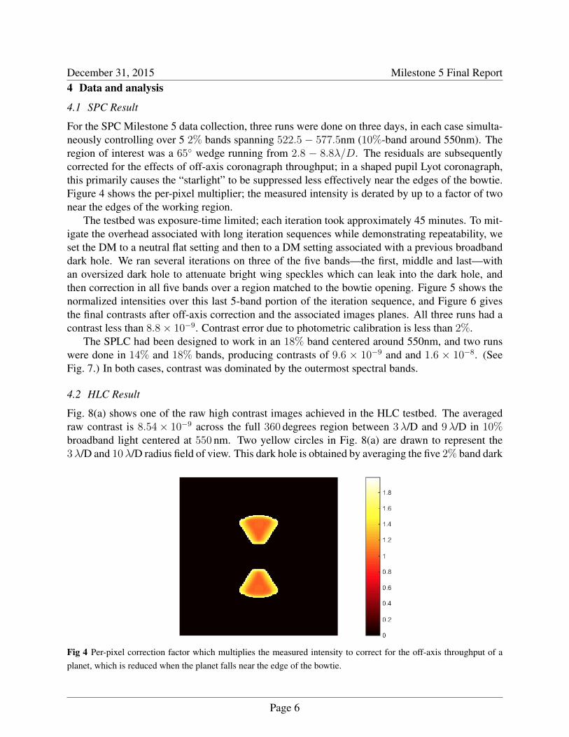
For the SPC Milestone 5 data collection, three runs were done on three days, in each case simulta-neously controlling over 5 2% bands spanning 522.5 − 577.5nm (10%-band around 550nm). Theregion of interest was a 65◦ wedge running from 2.8 − 8.8λ/D. The residuals are subsequentlycorrected for the effects of off-axis coronagraph throughput; in a shaped pupil Lyot coronagraph,this primarily causes the “starlight” to be suppressed less effectively near the edges of the bowtie.Figure 4 shows the per-pixel multiplier; the measured intensity is derated by up to a factor of twonear the edges of the working region.
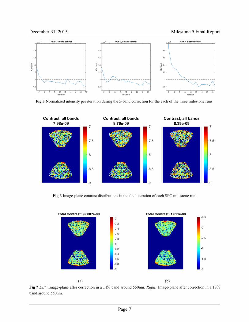
The testbed was exposure-time limited; each iteration took approximately 45 minutes. To mit-igate the overhead associated with long iteration sequences while demonstrating repeatability, weset the DM to a neutral flat setting and then to a DM setting associated with a previous broadbanddark hole. We ran several iterations on three of the five bands—the first, middle and last—withan oversized dark hole to attenuate bright wing speckles which can leak into the dark hole, andthen correction in all five bands over a region matched to the bowtie opening. Figure 5 shows thenormalized intensities over this last 5-band portion of the iteration sequence, and Figure 6 givesthe final contrasts after off-axis correction and the associated images planes. All three runs had acontrast less than 8.8× 10⁻⁹. Contrast error due to photometric calibration is less than 2%.
The SPLC had been designed to work in an 18% band centered around 550nm, and two runswere done in 14% and 18% bands, producing contrasts of 9.6 × 10⁻⁹ and and 1.6 × 10⁻⁸. (SeeFig. 7.) In both cases, contrast was dominated by the outermost spectral bands.
4.2 HLC Result
Fig. 8(a) shows one of the raw high contrast images achieved in the HLC testbed. The averagedraw contrast is 8.54× 10⁻⁹ across the full 360 degrees region between 3λ/D and 9λ/D in 10%broadband light centered at 550 nm. Two yellow circles in Fig. 8(a) are drawn to represent the3λ/D and 10λ/D radius field of view. This dark hole is obtained by averaging the five 2% band dark
Fig 4 Per-pixel correction factor which multiplies the measured intensity to correct for the off-axis throughput of aplanet, which is reduced when the planet falls near the edge of the bowtie.
Page 6
December 31, 2015 Milestone 5 Final Report
Fig 5 Normalized intensity per iteration during the 5-band correction for the each of the three milestone runs.
Fig 6 Image-plane contrast distributions in the final iteration of each SPC milestone run.
(a) (b)
Fig 7 Left: Image-plane after correction in a 14% band around 550nm. Right: Image-plane after correction in a 18%
band around 550nm.
Page 7
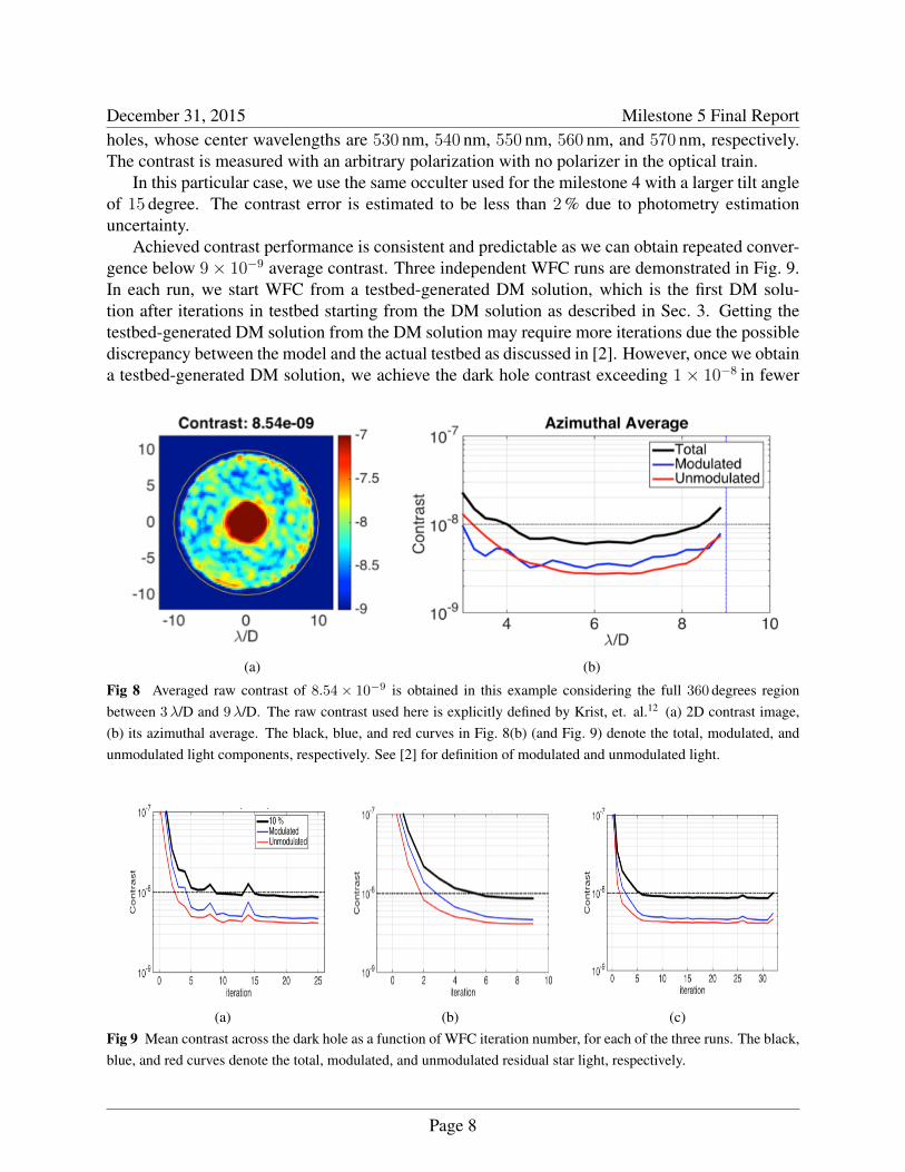
December 31, 2015 Milestone 5 Final Reportholes, whose center wavelengths are 530 nm, 540 nm, 550 nm, 560 nm, and 570 nm, respectively.The contrast is measured with an arbitrary polarization with no polarizer in the optical train.
In this particular case, we use the same occulter used for the milestone 4 with a larger tilt angleof 15 degree. The contrast error is estimated to be less than 2% due to photometry estimationuncertainty.
Achieved contrast performance is consistent and predictable as we can obtain repeated conver-gence below 9× 10⁻⁹ average contrast. Three independent WFC runs are demonstrated in Fig. 9.In each run, we start WFC from a testbed-generated DM solution, which is the first DM solu-tion after iterations in testbed starting from the DM solution as described in Sec. 3. Getting thetestbed-generated DM solution from the DM solution may require more iterations due the possiblediscrepancy between the model and the actual testbed as discussed in [2]. However, once we obtaina testbed-generated DM solution, we achieve the dark hole contrast exceeding 1× 10⁻⁸ in fewer
(a) (b)
Fig 8 Averaged raw contrast of 8.54× 10⁻⁹ is obtained in this example considering the full 360 degrees regionbetween 3λ/D and 9λ/D. The raw contrast used here is explicitly defined by Krist, et. al.12 (a) 2D contrast image,(b) its azimuthal average. The black, blue, and red curves in Fig. 8(b) (and Fig. 9) denote the total, modulated, andunmodulated light components, respectively. See [2] for definition of modulated and unmodulated light.
(a) (b) (c)Fig 9 Mean contrast across the dark hole as a function of WFC iteration number, for each of the three runs. The black,blue, and red curves denote the total, modulated, and unmodulated residual star light, respectively.
Page 8
December 31, 2015 Milestone 5 Final Reportthan 10 iteration cycles for every run, as shown in Fig. 9. The iteration period is approximately15minutes.
5 Conclusion and Future Work
The next step in the OMC technology maturation plan is Milestone 9, which is the starlight sup-pression demonstration in presence of simulated input wavefront disturbances expected on-orbit bythe WFIRST-AFTA observatory. For this, a new OMC testbed has been designed, built and aligned.This testbed, analogously to the OMC flight instrument architecture, can be operated in two dif-ferent modes: HLC and SPC. In the new dynamic OMC testbed, the AFTA Optical TelescopeAssembly Simulator (OTA-S) serves as the front end. OTA-S has been built and demonstrated forMilestone 6 and is a sophisticated piece of ground support equipment designed to introduce line-of-site and other low order wavefront perturbations expected on-orbit on relevant timescales. TheOMC will be presented with realistic dynamic input wavefront from the OTA-S and will rely on itsLOWFS/C subsystem to sense and correct the dynamic wavefront down to the level that permitsthe WFIRST OMC to meet its science goals. Thus, the Milestone 9 will serve as an integrated andcomplete demonstration of the capabilities first shown for Milestones 5 and 6 on three separatetestbeds. Milestone 9 is due in late 2016.
6 Acronyms
CGI Coronagraphic Instrument . . . . . . . . . . . . . . . . . . . . . . . . . . . . . . . . . . . . . . . . . . . . . . . . . . . . . . . . 2
DM Deformable Mirror . . . . . . . . . . . . . . . . . . . . . . . . . . . . . . . . . . . . . . . . . . . . . . . . . . . . . . . . . . . . . . 2
EFC Electric Field Conjugation . . . . . . . . . . . . . . . . . . . . . . . . . . . . . . . . . . . . . . . . . . . . . . . . . . . . . . . .5
FSM Fast Steering Mirror . . . . . . . . . . . . . . . . . . . . . . . . . . . . . . . . . . . . . . . . . . . . . . . . . . . . . . . . . . . . . 2
HCIT High Constrast Imaging Testbed . . . . . . . . . . . . . . . . . . . . . . . . . . . . . . . . . . . . . . . . . . . . . . . . . . 2
HLC Hybrid Lyot Coronagraph . . . . . . . . . . . . . . . . . . . . . . . . . . . . . . . . . . . . . . . . . . . . . . . . . . . . . . . . 1
LOWFS/C Low Order Wavefront Sensing and Control . . . . . . . . . . . . . . . . . . . . . . . . . . . . . . . . . . . . . 2
LoS Line of Sight . . . . . . . . . . . . . . . . . . . . . . . . . . . . . . . . . . . . . . . . . . . . . . . . . . . . . . . . . . . . . . . . . . . . 2
NASA National Aeronautics and Space Administration . . . . . . . . . . . . . . . . . . . . . . . . . . . . . . . . . . . . 2
OMC Occulting Mask Coronagraph . . . . . . . . . . . . . . . . . . . . . . . . . . . . . . . . . . . . . . . . . . . . . . . . . . . . . 2
PSF Point Spread Function . . . . . . . . . . . . . . . . . . . . . . . . . . . . . . . . . . . . . . . . . . . . . . . . . . . . . . . . . . . 2
SPC Shape Pupil Coronagraph . . . . . . . . . . . . . . . . . . . . . . . . . . . . . . . . . . . . . . . . . . . . . . . . . . . . . . . . 1
SPLC Shape Pupil Lyot Coronagraph. . . . . . . . . . . . . . . . . . . . . . . . . . . . . . . . . . . . . . . . . . . . . . . . . . . .3
TAC Technical Analysis Committee . . . . . . . . . . . . . . . . . . . . . . . . . . . . . . . . . . . . . . . . . . . . . . . . . . . . 2
WFC Wavefront Control
Page 9
December 31, 2015 Milestone 5 Final ReportAcknowledgments
Presented WFIRST-AFTA coronagraph technology development work was carried out at the JetPropulsion Laboratory using funding from NASA SMD and STMD. We acknowledge X. An, R.Diaz, D. Palmer, K. Patterson, D. Ryan, F. Shi, R. Zimmer and H. Tang for their contribution totestbed layout, assembly, and alignment, J. Krist for modeling advice, F. Greer, K. Balasubrama-nian, V. White, and R. Calvet for device fabrication, S. Macenka, and F. Zhao for programmaticadvice.
References1 E. Cady, X. An, B. Balasubramanian, R. Diaz, J. Kasdin, B. Kern, A. Kuhnert, B. Nemati,
K. Patterson, I. Poberezhskiy, A. Riggs, D. Ryan, H. Zhou, and R. Z. N. Zimmerman, “Mile-stone 2 final report: Shaped pupil narrowband contrast,” JPL Document , 2014.
2 B.-J. Seo, B. Gordon, B. Kern, A. Kuhnert, D. Moody, R. Muller, I. Poberezhskiy, J. Trauger,and D. Wilson, “Milestone 4 Final Report: Narrowband Contrast Testbed Demonstration ofHybrid Lyot Coronagraph for WFIRST-AFTA,” JPL Document , 2014.
3 E. Cady, C. Mejia Prada, X. An, K. Balasubramanian, R. Diaz, N. J. Kasdin, B. Kern,A. Kuhnert, B. Nemati, I. Poberezhskiy, A. J. E. Riggs, R. Zimmer, and N. Zimmerman,“Demonstration of high contrast with an obscured aperture with the wfirst-afta shaped pupilcoronagraph,” Journal of Astronomical Telescopes, Instruments, and Systems Special Section,SPIE 2(1), p. 011004, 2015.
4 B.-J. Seo, B. Gordon, B. Kern, A. Kuhnert, D. Moody, R. Muller, I. Poberezhskiy, J. Trauger,and D. Wilson, “Hybrid Lyot Coronagraph for WFIRST-AFTA: Occulter Fabrication andHigh Contrast Narrowband Testbed Demonstration,” Journal of Astronomical Telescopes,Instruments, and Systems Special Section, SPIE , 2015.
5 J. Trauger, B. Gordon, J. Krist, and D. Moody., “Hybrid Lyot Coronagraph for WFIRST-AFTA: coronagraph design and performance metrics (To be published),” Journal of Astro-nomical Telescopes, Instruments, and Systems Special Section, SPIE , 2015.
6 N. Zimmerman, A. J. E. Riggs, N. J. Kasdin, A. Carlotti, and R. Vanderbei, “Shaped pupillyot coronagraphs: High-contrast solutions for restricted focal planes,” Accepted by JATIS ,2015.
7 J. Trauger, D. Moody, and B. Gordon, “Complex apodized Lyot coronagraph for exoplanetimaging with partially obscured telescope apertures,” 2013.
8 K. Balasubramanian, V. White, K. Yee, P. Echternach, R. Muller, M. Dickie, E. Cady, C. M.Prada, D. Ryan, I. Poberezhskiy, B. Kern, H. Zhou, J. Krist, B. Nemati, A. J. Eldorado Riggs,N. T. Zimmerman, and N. J. Kasdin, “WFIRST-AFTA coronagraph shaped pupil masks:design, fabrication, and characterization,” Journal of Astronomical Telescopes, Instruments,and Systems 2(1), p. 011005, 2015.
9 J. Trauger, D. Moody, B. Gordon, J. Krist, and D. Mawet, “A hybrid lyot coronagraph for thedirect imaging and spectroscopy of exoplanet systems: recent results and prospects,” 2011.
10 A. Give’on, B. D. Kern, and S. Shaklan, “Pair-wise, deformable mirror, image plane-baseddiversity electric field estimation for high contrast coronagraphy,” in Society of Photo-OpticalInstrumentation Engineers (SPIE) Conference Series, Society of Photo-Optical Instrumenta-tion Engineers (SPIE) Conference Series 8151, Sept. 2011.
Page 10

December 31, 2015 Milestone 5 Final Report11 A. Give’on, “A unified formalism for high contrast imaging correction algorithms,” Tech-
niques and Instrumentation for Detection of Exoplanets IV 7440, p. 74400D, SPIE, 2009.12 J. Krist, B. Nemati, and B. Mennesson, “Numerical modelling of the proposed WFIRST-
AFTA coronagraphs and their predicted performances,” Journal of Astronomical Telescopes,Instruments, and Systems Special Section, SPIE , 2015.
Page 11