Embed Size (px)
Citation preview
Available online at www.sciencedirect.com
Energy Procedia 00 (2014) 000–000
www.elsevier.com/locate/procedia
1876-6102© 2014 The Authors. Published by Elsevier Ltd.
Selection and peer-review under responsibility of EUROSOLAR - The European Association for Renewable Energy.
8th International Renewable Energy Storage Conference and Exhibition, IRES 2013
Minewater 2.0 project in Heerlen the Netherlands: transformation of a
geothermal mine water pilot project into a full scale hybrid sustainable energy
infrastructure for heating and cooling
René Verhoeven1*
, Eric Willems2, Virginie Harcouët-Menou
3, Eva De Boever
3, Louis Hiddes
1 , Peter Op ’t Veld
2,
Elianne Demollin1
1 Mine Water Heerlen, PO Box 1, 6400AA Heerlen, The Netherlands
2Cauberg-Huygen Consulting Engineers, PO Box 480, 6200AL Maastricht, The Netherlands
3 VITO, Boeretang 200, 2400 Mol, Belgium
Abstract
In the last 10 years numerous research and commercial initiatives have been undertaken in Europe to develop abandoned coal
mining fields into low-temperature resources. One of the most successful is the Minewater project of the municipality of Heerlen,
the Netherlands, where a low-temperature district heating system was launched in operation in October 2008, under the European
Interreg IIIB NWE programme and the 6th Framework Program project EC-REMINING-lowex. The Minewater project is now
being upgraded from a straight forward pilot system to a full-scale hybrid sustainable energy structure called Minewater 2.0. A
totally new concept which becomes an essential part of the Sustainable Energy Structure Plan of Heerlen and has the following
landmarks:
Energy exchange instead of energy supply: cluster grids for energy exchange between buildings and the existing mine water
grid for energy exchange between cluster grids.
Energy storage and regeneration in mine water reservoirs instead of depletion.
Addition of poly-generation: bio-CHP, solar energy, feed in of waste heat (data centres and industry), cooling towers for
peak cold demands.
Enlargement hydraulic and thermal capacity mine water grid through improving well pumps, pressure boosting systems and
reuse of the existing mine water return pipe for additional supply and disposal of hot mine water.
* Rene Verhoeven. Tel: 00316 37330624 | E-mail: [email protected]
Verhoeven, Willems, Harcouët-Menou, De Boever, Hiddes, Op ’t Veld, Demollin/Minewater 2.0 (2013)
Fully automatic and demand-driven supply of hot and cold mine water through usage of pressurized buffer systems at the
extraction wells and sophisticated injections valves at the injection wells.
All geographically dispersed mine water installations at buildings, clusters and wells are equipped with sophisticated
process control units that communicate with a Central Monitoring System (CMS) through the internet. A very new
application in the build environment.
The first phase of the Minewater 2.0 project is in operation since June 2013. In November 2013 at the congress we will be able to
share the first experiences.
Keywords: Geothermal energy; mine water; smart heat and cold grid; energy storage.
___________________________________________________________________________________________
1. Introduction
In the last 10 years numerous research and commercial initiatives have been undertaken in Europe to develop abandoned coal mining fields in to low-temperature resources. One of the most successful is the Minewater project of the municipality of Heerlen, the Netherlands, where a low-temperature district heating system was launched in operation in October 2008, under the European Interreg IIIB NWE programme and the 6th Framework Program project EC-REMINING-lowex. The Minewater project is now being upgraded from a straight forward pilot system to a full-scale hybrid sustainable energy structure called Minewater 2.0. In this paper the aspects and operation of this smart grid for heating and cooling is explained.
2. Minewater 1.0
Minewater 1.0 is the term used for the initial mine water system at Heerlen, developed in de period 2003 - 2008. A
straight forward pilot system to investigate how the mine water of the abandoned coal mines of Oranje Nassau could
be used as a geothermal source for the sustainable low-exergy heating and cooling of buildings.
Five wells were drilled to the stone drifts in the underground (see figure 1). Two hot wells in the northern part of
Heerlen with a depth of 700 meters below surface for the extraction of hot water with a temperature of about 28 °C,
two cold wells in the southern part of Heerlen with a depth of 250 meters for the extraction of cold mine water with
a temperature of about 16 °C. A fifth well in the middle part of Heerlen with a depth of 350 meters is used for the
injecting of the cooled hot and warmed cold mine water with intermediate temperatures between 18-22 °C.
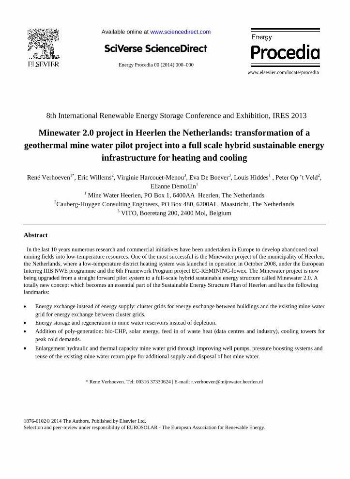
Through a three-pipe mine water distribution network of seven kilometers in length, the so called mine water
Fig. 1. Minewater 1.0 in geographical perspective Fig. 2. The energy station is situated in the basement of the
Heerlerheide Centrum (HHC).
Verhoeven, Willems, Harcouët-Menou, De Boever, Hiddes, Op ’t Veld, Demollin/Minewater 2.0 (2013)
backbone, the mine water from the wells is provided to the energy stations of the connected buildings. One pipe for
delivery of hot mine water (insulated) from the hot wells HH1 and HH2, one pipe for the delivery of cold mine
water (non-insulated) from the cold wells HLN1 and HLN2 and one return pipe (non-insulated) to return the used
mine water (hot and cold) to the injection well HLN3. Energy exchange in the energy plant of the end-users takes
place through heat exchangers. The hot mine water is cooled down by 10 °K and the cold mine water is heated up by
6 °K. Until 2012 one hot well HH1, one cold well HLN1 and the return well HLN3 were in operation with two end-
users: the office of the Central Bureau of Statistics (CBS; 22.000 m2) and the complex Heerlerheide Centrum (HHC;
homes, supermarket, offices, community facilities, catering; 30.000 m2) as shown in figure 2. Heat pumps in each
building are used to provide the base load of heat and cold at the demanded low-ex temperatures.
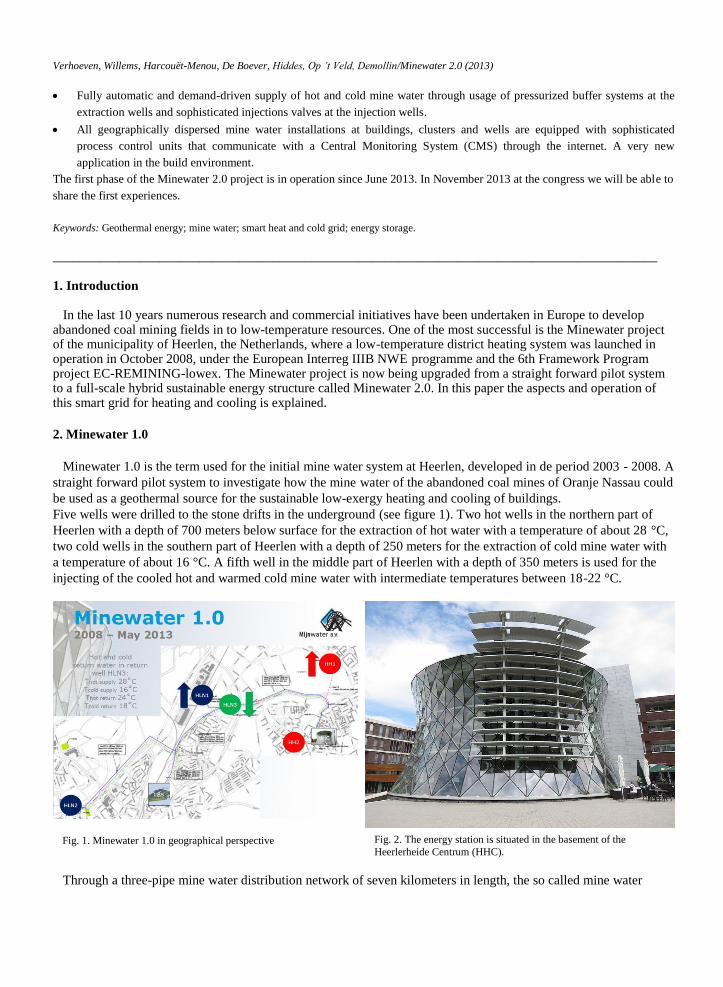
Figure 3 shows the 3-D model of the mine water reservoir. The simulations are conducted by using a numerical
model in which the detailed geometry of the relevant stone-drifts and shafts has been incorporated based on the
original mine maps. The used model reflects the status and knowledge acquired until mid-2012. It has been
calibrated based on pump tests that have been conducted in the early stages of the project and past production
periods. The numerical model of the mine water reservoir takes into account heat transfer by advection, mixing of
waters with different temperatures and heat conduction (exchange of heat between rock and water).
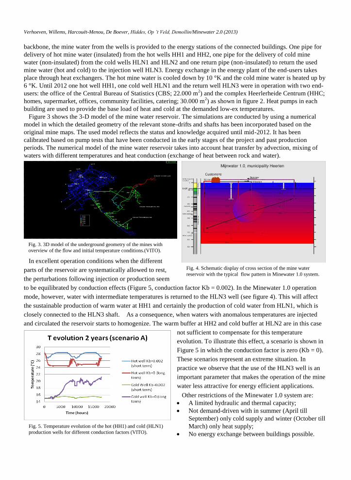
In excellent operation conditions when the different
parts of the reservoir are systematically allowed to rest,
the perturbations following injection or production seem
to be equilibrated by conduction effects (Figure 5, conduction factor Kb = 0.002). In the Minewater 1.0 operation
mode, however, water with intermediate temperatures is returned to the HLN3 well (see figure 4). This will affect
the sustainable production of warm water at HH1 and certainly the production of cold water from HLN1, which is
closely connected to the HLN3 shaft. As a consequence, when waters with anomalous temperatures are injected
and circulated the reservoir starts to homogenize. The warm buffer at HH2 and cold buffer at HLN2 are in this case
not sufficient to compensate for this temperature
evolution. To illustrate this effect, a scenario is shown in
Figure 5 in which the conduction factor is zero (Kb = 0).
These scenarios represent an extreme situation. In
practice we observe that the use of the HLN3 well is an
important parameter that makes the operation of the mine
water less attractive for energy efficient applications.
Other restrictions of the Minewater 1.0 system are:
A limited hydraulic and thermal capacity;
Not demand-driven with in summer (April till
September) only cold supply and winter (October till
March) only heat supply;
No energy exchange between buildings possible.
Fig. 3. 3D model of the underground geometry of the mines with
overview of the flow and initial temperature conditions.(VITO).
Fig. 4. Schematic display of cross section of the mine water
reservoir with the typical flow pattern in Minewater 1.0 system.
Fig. 5. Temperature evolution of the hot (HH1) and cold (HLN1)
production wells for different conduction factors (VITO).
Verhoeven, Willems, Harcouët-Menou, De Boever, Hiddes, Op ’t Veld, Demollin/Minewater 2.0 (2013)
3. Minewater 2.0
To make the minewater system future proof and to overcome the restrictions of de mine water pilot system a total
new concept Minewater 2.0 is developed based on the following elements:
Energy exchange instead of energy supply;
Energy storage instead of depletion;
Addition of poly generation to the system;
Maximizing the hydraulic and thermal capacity (reservoir, wells and distribution backbone);
Fully automatically controlled and demand driven system (heat and cold supply at any time);
The addition of heat and cold storage in the buildings and cluster grids (Minewater 3.0);
A system suitable for demand and supply side management in near future (Minewater 3.0).
3.1 Energy exchange, storage and regeneration of wells
3.1.1. Energy exchange
Energy exchange will be realised by the means of:
Local cluster grids for instant energy exchange (heat and cold) between the connected buildings in the cluster.
Application of the existing mine water backbone for energy exchange (heat and cold) between the
geographically dispersed cluster grids.
In this way a building is no longer only an energy consumer but also an energy supplier. A building that extracts
heat from the cluster grid supplies cold to the grid, which can instantly be uses by other buildings connected to the
grid. Another important advantage of cluster networks is that these are closed systems and can be run with clean
water. In cluster grids no special materials resistant to the corrosive mine water are needed like stainless steel (AISI
316) or plastic (PE or PP). Application of cast iron and a provision for simple water treatment are sufficient. This
means an important cost reduction of the cluster grid.
3.1.2. Energy storage and regeneration
The extraction wells (HH1 and HLN1) supply the shortage of heat and cold to the mine water backbone. Surplus
of heat and cold will be stored in the mine water reservoir through the hot and cold injection well (HH2 en HLN2).
The current return/injection well HLN3 will be out of order and only be used in case of exceptional situations.
Minewater 2.0 needs to be future proof. Unwanted intermediate return temperatures as applied in de mine water
pilot system (Minewater 1.0) cause depletion of the mine water reservoir. To eliminate this effect it is necessary that
the used return mine water is heated up or cooled down properly to the natural geothermal temperature and brought
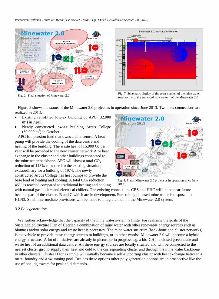
back to the corresponding hot or cold part of the mine water reservoir (see figure 6).
It is also important that the heat and cold extraction and infiltration has to maintain a sort of energy balance on a
yearly basis. In other words it is important that the mine water reservoir is regenerated. Determinative for the correct
water return temperatures to the mine water reservoir is the operation of the energy stations of the end-users. They
have to ensure that the hot water is cooled down (< 16˚C) and heated up (> 28˚C) sufficiently. This is included as
one of the conditions in the contract for end users of mine water.
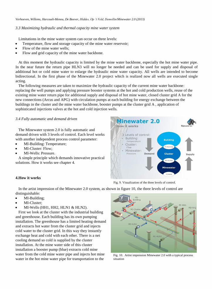
Figure 7 shows a schematic display of the cross section of the mine water reservoir with the enhanced flow pattern
of the Minewater 2.0 system. With this flow pattern practically no exchange between the hot and cold part of the
mine water reservoir occurs and in time a hot and cold bubble is built up which enlarges the useful energy storage
capacity of the mine water reservoir.
Verhoeven, Willems, Harcouët-Menou, De Boever, Hiddes, Op ’t Veld, Demollin/Minewater 2.0 (2013)
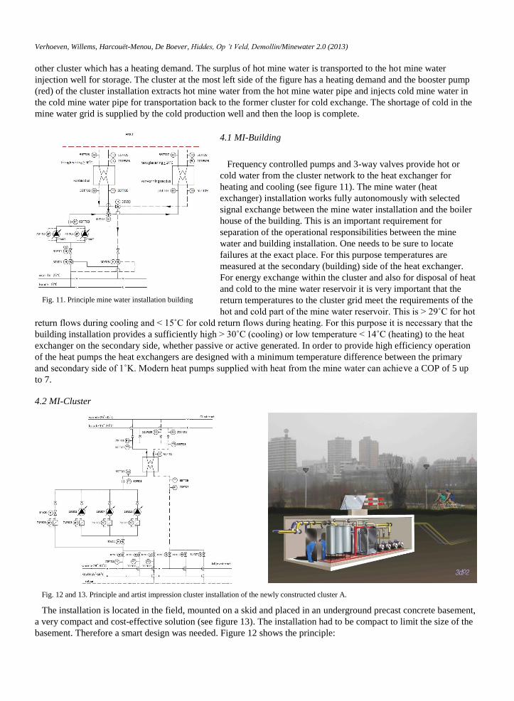
Figure 8 shows the status of the Minewater 2.0 project as in operation since June 2013. Two new connections are
realized in 2013:
Existing retrofitted low-ex building of APG (32.000
m2) in April;
Newly constructed low-ex building Arcus College
(30.000 m2) in October.
APG is a pension fund that owns a data centre. A heat
pump will provide the cooling of the data centre and
heating of the building. The waste heat of 15.000 GJ per
year will be provided to the new cluster network A or heat
exchange in the cluster and other buildings connected to
the mine water backbone. APG will show a total CO2
reduction of 118% compared to the existing situation,
extraordinary for a building of 1974. The newly
constructed Arcus College has heat pumps to provide the
base load of heating and cooling. A total CO2 reduction
45% is reached compared to traditional heating and cooling
with natural gas boilers and electrical chillers. The existing connections CBS and HHC will in the near future
become part of the clusters B and C which are in development. For so long the used mine water is disposed to
HLN3. Small intermediate provisions will be made to integrate them in the Minewater 2.0 system.
3.2 Poly generation
We further acknowledge that the capacity of the mine water system is finite. For realizing the goals of the
Sustainable Structure Plan of Heerlen a combination of mine water with other renewable energy sources such as
biomass and/or solar energy and waste heat is necessary. The mine water structure (back-bone and cluster networks)
is the vehicle to provide these energy sources to buildings, or in other words: Minewater 2.0 will become a hybrid
energy structure. A lot of initiatives are already in picture or in progress e.g. a bio-CHP, a closed greenhouse and
waste heat of an additional data centre. All these energy sources are locally situated and will be connected to the
nearest cluster gird to supply their heat and cold to the corresponding cluster and through the mine water backbone
to other clusters. Cluster D for example will initially become a self-supporting cluster with heat exchange between a
metal foundry and a swimming pool. Besides these options other poly generation options are in prospective like the
use of cooling towers for peak cold demands.
Fig. 8. Status Minewater 2.0 project as in operation since June
2013.
Fig. 6. Final situation of Minewater 2.0 Fig. 7. Schematic display of the cross section of the mine water
reservoir with the enhanced flow pattern of the Minewater 2.0
system.
Verhoeven, Willems, Harcouët-Menou, De Boever, Hiddes, Op ’t Veld, Demollin/Minewater 2.0 (2013)
3.3 Maximizing hydraulic and thermal capacity mine water system
Limitations in the mine water system can occur on three levels:
Temperature, flow and storage capacity of the mine water reservoir;
Flow of the mine water wells;
Flow and grid capacity of the mine water backbone.
At this moment the hydraulic capacity is limited by the mine water backbone, especially the hot mine water pipe.
In the near future the return pipe HLN3 will no longer be needed and can be used for supply and disposal of
additional hot or cold mine water to enlarge the hydraulic mine water capacity. All wells are intended to become
bidirectional. In the first phase of the Minewater 2.0 project which is realized now all wells are executed single
acting.
The following measures are taken to maximize the hydraulic capacity of the current mine water backbone:
replacing the well pumps and applying pressure booster systems at the hot and cold production wells, reuse of the
existing mine water return pipe for additional supply and disposal of hot mine water, closed cluster grid A for the
new connections (Arcus and APG) with circulation pumps at each building for energy exchange between the
buildings in the cluster and the mine water backbone, booster pumps at the cluster grid A , application of
sophisticated injections valves at the hot and cold injection wells.
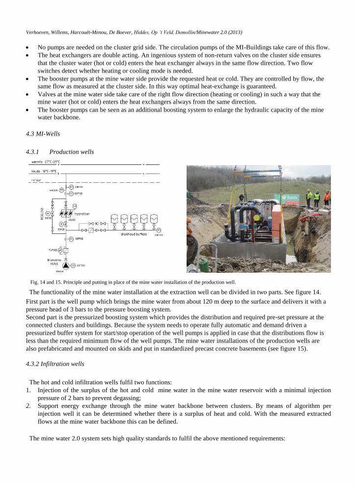
3.4 Fully automatic and demand driven
The Minewater system 2.0 is fully automatic and
demand driven with 3 levels of control. Each level works
with another independent process control parameter:
MI-Building: Temperature;
MI-Cluster: Flow;
MI-Wells: Pressure.
A simple principle which demands innovative practical
solutions. How it works see chapter 4.
4.How it works
In the artist impression of the Minewater 2.0 system, as shown in figure 10, the three levels of control are
distinguishable:
MI-Building;
MI-Cluster;
MI-Wells (HH1, HH2, HLN1 & HLN2).
First we look at the cluster with the industrial building
and greenhouse. Each building has its own pumping
installation. The greenhouse has a limited heating demand
and extracts hot water from the cluster grid and injects
cold water to the cluster grid. In this way they instantly
exchange heat and cold with each other. There is a net
cooling demand so cold is supplied by the cluster
installation. At the mine water side of this cluster
installation a booster pump (blue) extracts cold mine
water from the cold mine water pipe and injects hot mine
water in the hot mine water pipe for transportation to the
Fig. 9. Visualization of the three levels of control.
Fig. 10. Artist impression Minewater 2.0 with a typical process
situation
Verhoeven, Willems, Harcouët-Menou, De Boever, Hiddes, Op ’t Veld, Demollin/Minewater 2.0 (2013)
other cluster which has a heating demand. The surplus of hot mine water is transported to the hot mine water
injection well for storage. The cluster at the most left side of the figure has a heating demand and the booster pump
(red) of the cluster installation extracts hot mine water from the hot mine water pipe and injects cold mine water in
the cold mine water pipe for transportation back to the former cluster for cold exchange. The shortage of cold in the
mine water grid is supplied by the cold production well and then the loop is complete.
4.1 MI-Building
Frequency controlled pumps and 3-way valves provide hot or
cold water from the cluster network to the heat exchanger for
heating and cooling (see figure 11). The mine water (heat
exchanger) installation works fully autonomously with selected
signal exchange between the mine water installation and the boiler
house of the building. This is an important requirement for
separation of the operational responsibilities between the mine
water and building installation. One needs to be sure to locate
failures at the exact place. For this purpose temperatures are
measured at the secondary (building) side of the heat exchanger.
For energy exchange within the cluster and also for disposal of heat
and cold to the mine water reservoir it is very important that the
return temperatures to the cluster grid meet the requirements of the
hot and cold part of the mine water reservoir. This is > 29˚C for hot
return flows during cooling and < 15˚C for cold return flows during heating. For this purpose it is necessary that the
building installation provides a sufficiently high > 30˚C (cooling) or low temperature < 14˚C (heating) to the heat
exchanger on the secondary side, whether passive or active generated. In order to provide high efficiency operation
of the heat pumps the heat exchangers are designed with a minimum temperature difference between the primary
and secondary side of 1˚K. Modern heat pumps supplied with heat from the mine water can achieve a COP of 5 up
to 7.
4.2 MI-Cluster
The installation is located in the field, mounted on a skid and placed in an underground precast concrete basement,
a very compact and cost-effective solution (see figure 13). The installation had to be compact to limit the size of the
basement. Therefore a smart design was needed. Figure 12 shows the principle:
Fig. 11. Principle mine water installation building
Fig. 12 and 13. Principle and artist impression cluster installation of the newly constructed cluster A.
Verhoeven, Willems, Harcouët-Menou, De Boever, Hiddes, Op ’t Veld, Demollin/Minewater 2.0 (2013)
No pumps are needed on the cluster grid side. The circulation pumps of the MI-Buildings take care of this flow.
The heat exchangers are double acting. An ingenious system of non-return valves on the cluster side ensures
that the cluster water (hot or cold) enters the heat exchanger always in the same flow direction. Two flow
switches detect whether heating or cooling mode is needed.
The booster pumps at the mine water side provide the requested heat or cold. They are controlled by flow, the
same flow as measured at the cluster side. In this way optimal heat-exchange is guaranteed.
Valves at the mine water side take care of the right flow direction (heating or cooling) in such a way that the
mine water (hot or cold) enters the heat exchangers always from the same direction.
The booster pumps can be seen as an additional boosting system to enlarge the hydraulic capacity of the mine
water backbone.
4.3 MI-Wells
4.3.1 Production wells
The functionality of the mine water installation at the extraction well can be divided in two parts. See figure 14.
First part is the well pump which brings the mine water from about 120 m deep to the surface and delivers it with a
pressure head of 3 bars to the pressure boosting system.
Second part is the pressurized boosting system which provides the distribution and required pre-set pressure at the
connected clusters and buildings. Because the system needs to operate fully automatic and demand driven a
pressurized buffer system for start/stop operation of the well pumps is applied in case that the distributions flow is
less than the required minimum flow of the well pumps. The mine water installations of the production wells are
also prefabricated and mounted on skids and put in standardized precast concrete basements (see figure 15).
4.3.2 Infiltration wells
The hot and cold infiltration wells fulfil two functions:
1. Injection of the surplus of the hot and cold mine water in the mine water reservoir with a minimal injection
pressure of 2 bars to prevent degassing;
2. Support energy exchange through the mine water backbone between clusters. By means of algorithm per
injection well it can be determined whether there is a surplus of heat and cold. With the measured extracted
flows at the mine water backbone this can be defined.
The mine water 2.0 system sets high quality standards to fulfil the above mentioned requirements:
Fig. 14 and 15. Principle and putting in place of the mine water installation of the production well.
Verhoeven, Willems, Harcouët-Menou, De Boever, Hiddes, Op ’t Veld, Demollin/Minewater 2.0 (2013)
High material quality. The mine water is corrosive, AISI316 is a prerequisite.
Large depth. To prevent degassing the injection of the mine water needs to take place at a depth of 120 m below
surface, 30 m below water level.
Large capacity range. The injection valves must handle a flow from 0 to 230 m3/h.
Remote adjustable injection pressure from 2 to 6 bars.
Suitable for bidirectional use in future. During the extraction of the mine water by a well pump the valve must
be fully opened with a minimum of pressure loss.
Completely lockable in case of operation of the opposite injection well.
Pressure resistant to 18 bars.
The valves are equipped with an independent hydraulic pressure control system with a simple control box so that
the valves even at a great depth can be controlled with a remote-adjustable injection pressure. The valves are
resistant to 18 bars. Because 24 bars can occur a second valve at ground level is provided in the well which
completely closes when the injection well is not in operation.
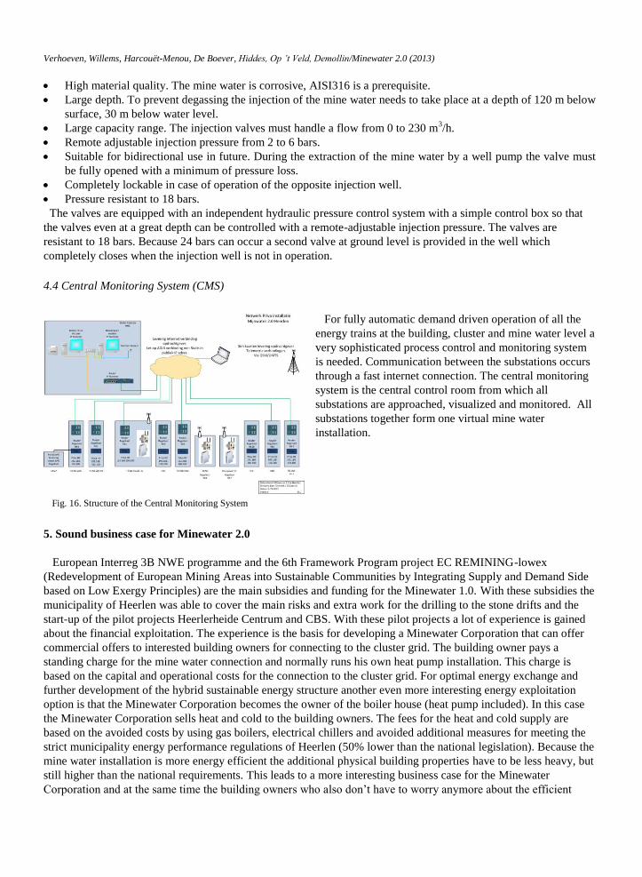
4.4 Central Monitoring System (CMS)
For fully automatic demand driven operation of all the
energy trains at the building, cluster and mine water level a
very sophisticated process control and monitoring system
is needed. Communication between the substations occurs
through a fast internet connection. The central monitoring
system is the central control room from which all
substations are approached, visualized and monitored. All
substations together form one virtual mine water
installation.
5. Sound business case for Minewater 2.0
European Interreg 3B NWE programme and the 6th Framework Program project EC REMINING-lowex
(Redevelopment of European Mining Areas into Sustainable Communities by Integrating Supply and Demand Side
based on Low Exergy Principles) are the main subsidies and funding for the Minewater 1.0. With these subsidies the
municipality of Heerlen was able to cover the main risks and extra work for the drilling to the stone drifts and the
start-up of the pilot projects Heerlerheide Centrum and CBS. With these pilot projects a lot of experience is gained
about the financial exploitation. The experience is the basis for developing a Minewater Corporation that can offer
commercial offers to interested building owners for connecting to the cluster grid. The building owner pays a
standing charge for the mine water connection and normally runs his own heat pump installation. This charge is
based on the capital and operational costs for the connection to the cluster grid. For optimal energy exchange and
further development of the hybrid sustainable energy structure another even more interesting energy exploitation
option is that the Minewater Corporation becomes the owner of the boiler house (heat pump included). In this case
the Minewater Corporation sells heat and cold to the building owners. The fees for the heat and cold supply are
based on the avoided costs by using gas boilers, electrical chillers and avoided additional measures for meeting the
strict municipality energy performance regulations of Heerlen (50% lower than the national legislation). Because the
mine water installation is more energy efficient the additional physical building properties have to be less heavy, but
still higher than the national requirements. This leads to a more interesting business case for the Minewater
Corporation and at the same time the building owners who also don’t have to worry anymore about the efficient
Fig. 16. Structure of the Central Monitoring System
Verhoeven, Willems, Harcouët-Menou, De Boever, Hiddes, Op ’t Veld, Demollin/Minewater 2.0 (2013)
operation of the boiler house and the requirements of the mine water connection. This becomes the responsibility of
the Minewater Corporation who has more degrees of freedom in order to fill in the energy supply and exploitation in
combination with other collective sustainable energy production plants connected to the Minewater 2.0 smart grid.
Because the Minewater Corporation also owns the heat pump installation she has the position of buying centralized
electricity for all the owned boiler houses and she can also benefit from PV-panels on the roofs of the buildings. At
this time the Minewater Corporation makes a bid based on the two different options mentioned above. In all cases
the commercial offer of the Minewater Corporation should be competitive to persuade potential customers to join
the Minewater 2.0 system. By doing so the Minewater Corporation may be of interest for private shareholders to
continue this business.
6. Conclusions
The Mine water project in Heerlen is now being upgraded from the straightforward pilot system to a smart grid
in heating and cooling with a full scale hybrid sustainable energy structure called Minewater 2.0 with 4 new
connections in 2013 - 2014. In 2015 in total 500.000 m2 floor area will be provided with mine water, which has
a CO2 emission reduction of 65% on heating and cooling for these connections.
The Minewater 2.0 project demands smart cost effective solutions. No rocket science but creative thinking and
new use of standard available solutions. Further technical development will be necessary to develop fine tuning
in cost effective design and operation of the grid installations.
Cluster grids are a profound solution to provide energy exchange between buildings.
By poly generation the power of the application of cluster grids and capacity of the mine water grid can be
strongly increased.
Cluster grid applications are used in combination with low temperature geothermal sources (mine water) but
can be applied in general with other sustainable heat and cold energy sources e.g. waste heat from data centres
and closed greenhouses.
The Minewater Corporation developing Minewater 2.0 proves that heat pump operation with low-ex heat
sources can be commercial feasible. Because it is economic feasibility the Minewater 2.0 system can and will become an essential part of the
Sustainable Energy Structure Plan of Heerlen witch reaches out towards 2040.
Acknowledgements
We thank the EC 6th
Framework and AgentschapNL for their financial support and for their trust in our ideas and
work during the realization of this new energy exchange concept.
References
[1] Swart, D (July 2006). End of Well Reports Heerlerheide #1 & Heerlerheide #, Groningen, the Netherlands, PGMi.
[2] Van Tongeren, P.C.H., Amann – Hildenbrand, A & Daneels, A. (April 2007). The Selection of ‘low’ and 'the intermediate’ temperature wells (HRL-1, -2 & -3) at the Heerlen mine water-project, Mol, Belgium. VITO NV.
[3] Watzlaf G.R. & Ackman, E.T. (2006). Underground Mine Water for Heating and Cooling using Geothermal Heat Pump Systems. Pittsburgh,
USA. IMWA Springer-Verlag. [4] Laenen, B, Harcouet-Menou V, & De Boever, E. Proposal pump test HLN2 – HLN3, Mol, Belgium, February 24, 2012. VITO NV.
[5] Laenen, B, Harcouet-Menou V, & De Boever, E. Evaluation impact of various supply scenarios on the mine water reservoirs, Mol,
Belgium, march, 2013. VITO NV [6] Laenen, B, Amann – Hildenbrand, A & Van Tongeren, P.C.H. (June 2007). The Heerlen mine water-project: Evaluation of the pump-test
data of July 2006 at the Heerlerheide-1 & -2 wells. Mol, Belgium. VITO NV
[7] Willems, E & Jablonska, B, Energy neutral building key to energy neutral districts, WREC 2011, Linkoping (2011) [8] Vidrih, B Medved, S Vetršek, & J Roijen, E, Standardized solutions for low exergy mine water systems configurations including solutions
for high quality energy demand, Technical Guidebook, Work package 2, Concerto Initiative, EC 6th Framework (2011).