Embed Size (px)
Citation preview

Miriam Vale Shire Council Supplementary Manual to Water Supply Standards WSA 03 2002 V2.3
Version 1.0 Date of Issue: Feb 2007 Page 1 of 24
Miriam Vale Shire Council
Water Supply Standards This document sets out the requirements for the design and construction of water supply systems for acceptance by Miriam Vale Shire Council as donated assets.
The Water Supply Code of Australia (WSCOA) is not reproduced in this document. The document can be obtained from the following organisations:
Water Services Association of Australia Standards Australia 469 Latrobe Street 1 The Crescent Melbourne Victoria 3000 Homebush NSW 2140
Miriam Vale Shire Councils water supply requirements are those contained in the Water Supply Code of Australia –WSA 03-2002 Version 2.3, published by the Water Services Association of Australia with the additions and amendments set out in this document. Part and Section references are those given in the WSCOA. Where no reference is made to a Section in the WSCOA, the Section applies in full without amendment.
If conflict is considered to exist between the WSCOA and an amendment the matter shall be referred to Council for resolution.
The water supply requirements are applicable to the majority of situations. However, variations may be necessary to meet special circumstances or to overcome other problems not addressed in the requirements. Whenever the proposed design varies in anyway from the requirements the proposed variation shall be authorised by Miriam Vale Shire Council.

Miriam Vale Shire Council Supplementary Manual to Water Supply Standards WSA 03 2002 V2.3
Version 1.0 Date of Issue: Feb 2007 Page 2 of 24
PART 0: GLOSSARY OF TERMS, ABBREVIATIONS AND REFERENCES
The following definitions from the WSCOA are reproduced below for the assistance of readers of this document.
Water Agency Miriam Vale Shire Council
Concept Plan A package of information provided to the Designer by the Water Agency to enable appropriate planning and design of major water supply system components to be performed.
Constructor An individual, corporation or legal entity including any contractors and sub-contractors that is accountable at law for delivery of Works under a specific contract or development agreement.
Developer A person, organisation, local government authority or government authority (other then the Water Agency) responsible for provision of a water supply scheme or water reticulation scheme.
Designer Person(s) or firm responsible for a design output. Such person or firm may be accountable to a Project Manager or other person having responsibility under a contract or otherwise.
Works All those Works being water mains, valves, hydrants and accessories and shall include valve chambers and storage facilities as shown on the Design Drawings and include any part of the Works.
Miriam Vale Shire Council Supplementary Manual to Water Supply Standards WSA 03 2002 V2.3
Version 1.0 Date of Issue: Feb 2007 Page 3 of 24
PART 1: PLANNING AND DESIGN
1.4 Design Output
Any variations to the Water Supply Standards, and the reasons for the variation, shall be highlighted in a boxed note on the design drawings.
1.5.2 Design Responsibilities – Water Agency Unless otherwise agreed, the Water Agency will provide a concept plan nominating the size and location of reticulation mains and pressure control valves, etc. The Water Agency will ensure that the trunk mains are capable of supplying the minimum standards of flow and pressure stipulated in the Water Supply and Sewerage Guidelines, DNR, Dec 2005. MVSC may make available a WaterCad model of the Agnes Water/1770 reticulation system.
1.5.3 The Designer The design of the works shall be carried out under the direction of and certified by a Registered Professional Engineer of Qld. (RPEQ). The Designer shall obtain the written approval from Council for any variations to the requirements of latest edition of WSA 03-2002 Water Code as amended by this Supplementary Manual prior to the submission of the final design.
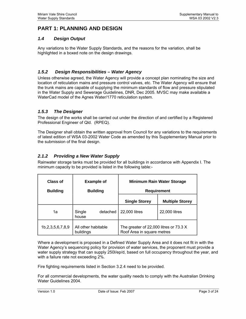
2.1.2 Providing a New Water Supply Rainwater storage tanks must be provided for all buildings in accordance with Appendix I. The minimum capacity to be provided is listed in the following table:-
Minimum Rain Water Storage
Requirement
Class of
Building
Example of
Building
Single Storey Multiple Storey
1a Single detached house
22,000 litres 22,000 litres
1b,2,3,5,6,7,8,9 All other habitable buildings
The greater of 22,000 litres or 73.3 X Roof Area in square metres
Where a development is proposed in a Defined Water Supply Area and it does not fit in with the Water Agency’s sequencing policy for provision of water services, the proponent must provide a water supply strategy that can supply 250l/ep/d, based on full occupancy throughout the year, and with a failure rate not exceeding 2%. Fire fighting requirements listed in Section 3.2.4 need to be provided. For all commercial developments, the water quality needs to comply with the Australian Drinking Water Guidelines 2004.
Miriam Vale Shire Council Supplementary Manual to Water Supply Standards WSA 03 2002 V2.3
Version 1.0 Date of Issue: Feb 2007 Page 4 of 24
2.2.1 Demands The reticulation system shall be designed to handle a flow rate of 450 l/ep/d. The ep density is to be based upon the design populations for particular developments listed in the Infrastructure Charges. Fire Fighting requirements shall be provided in accordance with Section 3.2.4
2.2.3 Peak Demands Peak demand factors are based on the DNR Water Supply Guidelines, October 1989. The following factors are to be used in modeling water supply demands:- Mean Day Maximum Month/Average Day =1.5 Maximum Day/Mean Day Maximum Month=1.5 Maximum Hour = 2 X Average Hour Demand for Maximum Day
2.3 System Configuration
Supply mains of DN250 and larger shall be classed a trunk mains. No service connections shall be permitted on trunk mains.
2.4.3 Operating Pressures – Amend Table 2.2
The minimum and maximum mains pressure for residential zones shall be 250kPa and 800kPa respectively. The minimum and maximum mains pressure for industrial/commercial properties shall be 300kPa and 800kPa respectively.
2.4.3.2 Maximum allowable service pressures The maximum allowable SP is 380kPa. The SP for consumers is measured at the water meter.
2.4.3.3 Minimum allowable service pressure The minimum allowable SP is 250kPa for residential zones and industrial/commercial properties.
2.6 Pumping Stations The conditions under which in-line boosters may be acceptable are: In–line booster pumping stations, without associated high-level storage, may be used in situations where all of the following conditions apply: (i) It is impractical to build storage; (ii) Duty Standby is provided (iii) Each property connection must have a minimum static pressure of 50kPa when the pump is offline; and (iv) The pump motor is to be variable speed.
3.2.1 Sizing of Mains – General The Water Agency standard reticulation main sizes are DN 100, 150, 200, 250 and 300.
Miriam Vale Shire Council Supplementary Manual to Water Supply Standards WSA 03 2002 V2.3
Version 1.0 Date of Issue: Feb 2007 Page 5 of 24
3.2.2 Minimum Pipe Sizes DN 63 PE shall be used in cul-de-sacs, subject to a maximum length of main of 40 m and not more than 8 water service connections.
3.2.4 Fire Flows Fire fighting requirements shall be provided in accordance with Water Supply and Sewerage Guidelines, DNR, Dec 2005, namely 15 l/s for 2 hours for residential areas and 30 l/s for 4 hours for commercial areas. These flows are to be superimposed upon 2/3 maximum hour demands for populations less than 2,000 ep, and maximum hour demands for populations greater than 3,000 ep.
3.2.5.3 Hydraulic Roughness Values The hydraulic analysis of the system shall utilise Hazen-Williams C roughness values of 150.
3.5.3 Table 3.2. Fatigue De-Rating For pumped mains, assume a minimum 6 cycles/day unless hydraulic modeling indicates otherwise, ie for boosted systems
3.7.2 Minimum pressure class
The minimum pressure class for water supply pipes and fittings shall be Class 12. PVC pipe shall be Series 2 Class 12 (AS/NZS 1477) minimum.
4 Hydraulic Design
Existing and proposed water supply systems upstream or downstream of the area under design shall be included in the hydraulic analyses. Design shall ensure that Standards of Service are maintained in existing or proposed water supply systems.
4.1.1 Design Tolerances Horizontal alignment shall be referenced to the Australian Map Grid coordinate system GDA 94.
4.3 Location of Water Mains
Water mains shall be located in accordance with Public Utilities in Subdivisions, Typical Service Conduit Sections, IMEAQ Standard Drawing R-0101.
Pipe fittings shall not be positioned under kerb and channel.
4.3.3 Water Mains in Easements
Easements are required where the main is not located in a dedicated road reserve.
The easement width shall be 3m for reticulation mains and 5m for trunk mains. The Developer shall arrange for the provision of easements.
Water mains shall not be located in an easement to reduce capital costs where a suitable route in a road reserve is available.
Miriam Vale Shire Council Supplementary Manual to Water Supply Standards WSA 03 2002 V2.3
Version 1.0 Date of Issue: Feb 2007 Page 6 of 24
4.3.6 Contaminated Sites
Applicant shall be referred to the appropriate State Government Agency during the IDAS approval process.
4.3.9 Railway Reserves Where a water main crosses a Railway Reserve a deed of Agreement is required between the Railway Authority and the Water Agency.
4.3.11 Overhead power lines and transmission towers Where the distance from a metal water mains to a power line or transmission tower is within the distances stated in this clause, a report detailing the procedures to be adopted for the construction and maintenance of the main shall be provided by a Registered Professional Engineer.
4.3.12 Tracer Wire and Marker Tape
Tracer wire of 2mm 316 stainless Steel cable, 7/19 construction shall be installed immediately above the marker tape on all water mains.
4.7 Connection of New Mains to Existing Mains Connections shall comply with: All works on the existing reticulation system shall be considered as “live works” and will be constructed by the Water Agency at the Contractor’s cost. These works shall be clearly delineated on the Design Drawings and shown in sufficient detail such that the works can be readily constructed . The connection point to the existing system shall be located to minimise disruption of supply to customers and be subject to Council approval. Acceptable connection arrangements (a) Extension from the end of an existing main.
A socketed or flanged valve shall be installed on the existing main as part of the "live works". The Contractors works shall commence from the valve.
(b) Side branch from an existing main.
A flange branch with a socketed or flanged valve shall be installed on the existing main as part of the “live works”. The Contractors works shall commence at the valve. If it is not possible to locate the valve adjacent to the existing main, the Contractors works shall commence with a gate valve at least 5 m from the existing main. If the proposed main crosses a roadway adjacent to the connection point, the full length of main at the road crossing shall be included in the “live” works.
(c) New main between existing mains. A flange branch with a socketed or flanged valve shall be installed on the existing main as part of the “live works”. The Contractors works shall construct from this valve to no closer than 5 m from the other main. The Water Agency shall complete any outstanding connections to the existing system after acceptance of the Contractors works.
Miriam Vale Shire Council Supplementary Manual to Water Supply Standards WSA 03 2002 V2.3
Version 1.0 Date of Issue: Feb 2007 Page 7 of 24
4.8 Termination Points
Where a future main is planned to extend the system beyond the development currently being serviced the water main shall finish with a valve. A legal right of way (easement or reserve) shall be provided 3 m wide through the adjoining allotment(s) to permit its future extension. The right of way shall be vested in Council.
4.8.3 Temporary ends of water mains A temporary dead-end termination point shall comprise a length of pipe extending from a scour fitting. When the main is to be extended, the dead end shall be removed, a valve fitted and the mains laid. If the extension is likely to occur shortly after construction of the main, a valve rather than a dead-end shall be installed.
4.9.1 Sizing of Property Services Standard sizes for water services are DN 20 and DN 25. Single residential lots shall have a DN 20 property service unless a DN 25 service has been requested by the property owner and agreed to by the Water Agency. Property services laid across a road shall be one size larger than the individual property connection. The mains tapping fittings and the meters are common for DN 20 and DN 25 services. If the long-term static head of the property service is less than 350 kPa (35m) or if private booster is required, the minimum size of property service shall be DN 32. All the sizes stated above relate to copper services. Polyethylene water services shall be one nominal DN size larger than that of a copper service.
4.9.2 Location of Property Services Where practicable, property service connection points shall be located 500 mm from the RP side boundary on the opposite side of the lot to the electrical service pillar-box. If, as may occur at corner properties, electrical pillar-boxes are located on both side boundaries, the property service connection shall be placed at the RP boundary truncation point. Services shall be located at least 0.5 m from electrical light poles and clear of existing or future driveways Property services laid along a footpath shall be located on a 1.2 m alignment from the RP boundary. DN 100 and 150 services shall terminate in the footway approximately 250 mm from the property boundary.
4.9.3 Multiple Property Services Multiple Property Services shall comply with: Multiple services will only be permitted for single residential lots where the services are laid across the road carriageway and shall be limited to serving 2 lots. Multiple services shall be laid in copper.
4.9.4 Property Service Conduits Water services up to DN32 which are located under existing or future roadways, concrete or paved driveways, footpaths, bikeways or other hardstand areas, shall be

Miriam Vale Shire Council Supplementary Manual to Water Supply Standards WSA 03 2002 V2.3
Version 1.0 Date of Issue: Feb 2007 Page 8 of 24
installed in a solvent welded DN 50 Class 12 PVC conduit. The conduit shall have a maximum length of 25 m and extend 150 mm beyond the back of the kerb or concrete/paved area. Conduits shall not be installed in the same trench as electrical cables. Brass or Stainless Steel markers indicating the service location shall be placed on the kerb or concrete/paving edge.
4.9.5 Tracer Wire and Marker Tape PE water services shall have a 2mm 316 stainless steel 7/19 construction cable plus marker tape placed 150mm above the pipe embedment. Where the PE service is placed inside a conduit the marking tape and tracer wire shall be placed 150mm above the conduit
4.9.6 Water Services DN100 and Greater Water services ≥ DN 100 shall be specified in DICL in accordance with the requirements for comparable sized DICL water mains. Vertical bends shall have flanged connections. SCL pipework is acceptable where space constraints prevent the use of DICL. PVC shall not be specified for water services.
4.9.7 Services to Community Title Schemes Community title schemes shall be provided with a single service to the property boundary. Responsibility for water supply charges rests with the Body Corporate.
4.10.5 Underground Obstructions & Services
The location of all existing services shall be confirmed with the appropriate Authority prior to the commencement of any excavation work.
Council takes no responsibility for the accuracy of any as constructed information.
4.10.5.2 Clearance Requirements Water mains shall be located with sufficient clearance to structures to allow for maintenance and operation activities and provide protection against damage from pipeline bursts.
4.10.7 Deviation of Mains Around Structures
The angle and type of all bends shall be shown on the Design Drawings
5.5.1 Geotechnical Considerations Where difficult ground conditions are anticipated a geotechnical and construction method report shall be submitted with the design.
5.6 Pipe materials For approved pipe materials refer to Appendix A. Where a proposed road crosses an existing AC main, the main shall be replaced with an approved material.
Miriam Vale Shire Council Supplementary Manual to Water Supply Standards WSA 03 2002 V2.3
Version 1.0 Date of Issue: Feb 2007 Page 9 of 24
5.9.1 Pipe Anchorage All DN100 and larger valves and tapers, including flanged items shall be secured with anchor blocks
5.9.2 Thrust blocks Thrust blocks shall be sized for a design pressure of 1200 kPa (120 m).
5.9.4 Restrained elastomeric joint seals Where space available for thrust blocks is limited, a commercial restrained joint system may be used subject to Water Agency approval.
6.1.2 Valves – Siting Principles Valves, hydrants and scours shall not be installed in trafficable roadways where an alternative location is available.
6.2 Stop Valves
Valves shall be anticlockwise closing. Resilient seat valves shall be used. Valve covers shall be in accordance with WAT-1304, Type H1.
6.2.3 Stop valves for reticulation mains Stop valves for reticulation mains shall be provided in accordance with Table 6.1 or as directed by the Water Agency.
6.4.2 Air Valves Type
Air valves shall be of Vent-o-Mat type valve or other approved equivalent.
6.7 Swabbing points Swabbing points are not required.
6.8 Hydrants
Hydrants shall not be installed on constant flow reticulation systems.
Hydrants shall be DN80 spring hydrants with the standard claw type head.
Hydrant boxes shall be painted safety yellow with glass beads embedded in the paint.
Hydrants shall be located in line with side boundaries of a lot and not more than 80 metres apart. A hydrant shall be located within 10 metres of an intersection.
Where the end of the water line is permanent, a duck foot bend hydrant shall be used. Hydrant covers shall be in accordance with WAT-1306, Type H2.
6.8.3 Hydrant types All hydrants shall be of the spring type with standard claw type head.
Miriam Vale Shire Council Supplementary Manual to Water Supply Standards WSA 03 2002 V2.3
Version 1.0 Date of Issue: Feb 2007 Page 10 of 24
6.8.6 Hydrant sizes Hydrants shall have DN 80 flanges. 6.8.7 Hydrant Spacing – The spacing of hydrants on water mains in urban areas shall comply with the following requirements: • within 40 m of property boundaries and within 90 m of the furthest point of the
building envelope measured around the perimeter of the building envelope, except that in residential in-fill areas only the 90 m requirement applies,
• at a maximum interval of 80 m, • as directed by the Water Agency
7.2 Design Drawings - General
Design Drawings shall comply with Miriam Vale Shire Council Planning Scheme Policy No. 1 - Appendix B.
7.3 As Constructed – General
As Constructed drawings shall comply with Section 8.4 of the Miriam Vale Shire Council Planning Scheme Policy No. 1.
Miriam Vale Shire Council Supplementary Manual to Water Supply Standards WSA 03 2002 V2.3
Version 1.0 Date of Issue: Feb 2007 Page 11 of 24
PART 2: PRODUCTS AND MATERIALS
8 Products and Materials Overview
As this area is reasonably remote, the types of materials utilised in water supply systems shall be limited such that the availability of spares is maximised and the inventory of spares carried by repair crews and Council stores is minimised.
Pipeline Materials
Below DN100 water mains shall be constructed in:
a. DN 63 PE (AS/NZS 4130) PN12, blue lined.
Between DN100 and DN250 (inclusive) water mains shall be constructed in:
b. uPVC AS/NZS 1477, Series 2 PN12 rubber ring joint;
c. PVC-M AS/NZS 4765, Series 2 PN 12 rubber ring joint;
d. OPVC AS/NZS 4441, Series 2 PN Class 12 rubber ring joint;
e. DICL AS/NZS 2280, PN35 rubber ring joint, polyethylene wrapped AS 3680.
DN300 and over water mains shall be constructed in:
f. DICL AS/NZS 2280, K9, rubber ring joint, polyethylene wrapped AS 3680;
Ductile Iron (Pipes)
DI pipe shall not be used in ground below RL 5.0 unless soil testing indicates that actual or potential acid sulphate soil conditions are not present.
Gibault Joints
Gibault joints shall be long barrel type with stainless steel (Grade 316) fasteners. Gibault joints used below RL5.0 or in the presence of actual or potential acid sulphate soils shall be protected by application of petrolatum mastic and tape wrap.
Stabilised Sand
Stabilised sand shall contain a minimum of 4% cement by weight.
Embedment Material
Where pipes are installed below RL 5.0 or are likely to be in contact with actual or potential acid sulphate soils, pipes shall be bedded using a limestone crusher dust material complying with the WSCOA grading requirements.
8.7 Additional Product and Material Information
Valves
Valves shall be PN 16 or better with spigot or socket joints and shall be anti-clockwise closing. Valves shall be fully coated internally and externally with thermo-bonded polymeric coatings in accordance with AS4158 (rilsan nylon 11 or similar approved coating).
Miriam Vale Shire Council Supplementary Manual to Water Supply Standards WSA 03 2002 V2.3
Version 1.0 Date of Issue: Feb 2007 Page 12 of 24
Valves shall be fitted with fully encapsulated rubber sealing wedges and o-ring seals, complying with AS 2638.2 - 2002. Stainless steel (316 grade) fasteners shall be used.
Hydrants
Hydrant tees shall have socket joints. Hydrants shall be DN80 spring hydrants coated internally and externally with thermo-bonded polymeric coatings in accordance with AS4158 (rilsan nylon 11 or similar approved coating).
All hydrants shall suit a DN100 tee or riser. Valve and hydrant boxes shall be in accordance with WAT-1304 to WAT-1306. All hydrants shall be supplied with coated metal caps.
Fittings
Socketed fittings shall be the elongated (extended barrel) type i.e. griptite/nortite or equivalent, suitable for PVC applications.
Gibault joints shall be the elongated (extended barrel) type.
All nuts, bolts and washers shall be Grade 316 Stainless Steel installed with nickel anti-seize grease or equivalent applied to the threads prior to assembly.
All fittings shall be fusion bonded polyethylene (FBE) coated ductile iron, complying with AS/NZS 2280 (2004) and AS/NZS 2518.
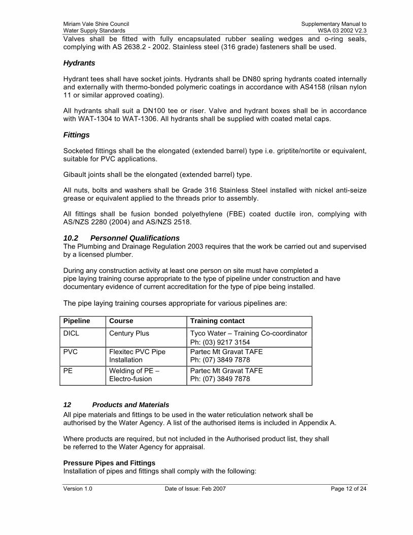
10.2 Personnel Qualifications The Plumbing and Drainage Regulation 2003 requires that the work be carried out and supervised by a licensed plumber. During any construction activity at least one person on site must have completed a pipe laying training course appropriate to the type of pipeline under construction and have documentary evidence of current accreditation for the type of pipe being installed. The pipe laying training courses appropriate for various pipelines are: Pipeline Course Training contact
DICL Century Plus Tyco Water – Training Co-coordinator Ph: (03) 9217 3154 PVC Flexitec PVC Pipe
Installation Partec Mt Gravat TAFE Ph: (07) 3849 7878
PE Welding of PE – Electro-fusion
Partec Mt Gravat TAFE Ph: (07) 3849 7878
12 Products and Materials All pipe materials and fittings to be used in the water reticulation network shall be authorised by the Water Agency. A list of the authorised items is included in Appendix A. Where products are required, but not included in the Authorised product list, they shall be referred to the Water Agency for appraisal. Pressure Pipes and Fittings Installation of pipes and fittings shall comply with the following:
Miriam Vale Shire Council Supplementary Manual to Water Supply Standards WSA 03 2002 V2.3
Version 1.0 Date of Issue: Feb 2007 Page 13 of 24
PVC Pipe PVC shall be laid in accordance with the requirements for laying PVC. PVC pipes shall not be cut within 1.5m of the socket and in general the minimum length of PVC pipe shall be 1.5m. (This requirement relates to the potential for longitudinal splits to occur down the main particularly if a hole is drilled in a short length of pipe. In addition short lengths of pipe have the potential to compound joint rotation increasing the possibility of spigot and socket disengagement.) Ductile iron or cast iron spigots shall not be joined to PVC sockets. Stainless steel repair clamps shall not be used on oPVC pipes FBE Coated Flanges FBE coated flanges shall be joined by Grade 316 stainless steel bolts, nuts and washers. In this configuration, flanges do not need to have a corrosion protection wrapping. Restrained Joint Rubber Sealing Rings Where restrained joints are used on DICL mains, the joint shall be installed in accordance with manufacturers written instructions. The joint shall be tested by inserting a feeler gauge to ensure that the rubber ring is installed with the correct depth. Where restrained joint DICL mains are used, a pink marking strip shall be placed over the top of the embedment material directly over the pipe to alert maintenance crews of the restrained joints. Steel pipes and Fittings Flanged Joints All flanged connections shall be tightened evenly and alternatively across the flange until a torque of 60 Nm for M 16 and 140 Nm for M 20 bolts is achieved. Hot-dip galvanised bolts, nuts and washers shall be used for flanged fittings within concrete valve chambers or above ground locations. Polyethylene Pipes and Fittings Only DR brass male threads shall be screwed directly into pre-tapped connectors or tapping bands. Male thread polyethylene connection fittings shall not be used in such connections. (Ground movement can cause the PVC fittings to shear at the thread interface.) Metallic male threads shall not be screwed into unrestrained plastic female threads. (Excessive tightening can cause the plastic socket to split, or over time, the joint can leak due to plastic creep.) Field butt welding of PE pipe shall be carried out by a suitably qualified welder. The minimum allowable bend radius for PE pipe is 25 x Pipe OD. PE pipe has a high coefficient of expansion (0.18mm/m/oC) and must be installed in the trench such that no thermal induced stresses develop on the pipe or fittings. The backfilling of side support and overlay zones shall not be placed when the ambient temperature adjacent to the pipe falls out side the range 12-27oC. The pipe shall be snaked horizontally in the trench to allow for thermal movement.
Miriam Vale Shire Council Supplementary Manual to Water Supply Standards WSA 03 2002 V2.3
Version 1.0 Date of Issue: Feb 2007 Page 14 of 24
PART 3: CONSTRUCTION
13.2 Limits of Excavation
Where excavation exceeds the required depth by more than 200mm, the excavated material shall be replaced with stabilised sand to the required level.
15.2.1 & 15.2.3 Bending of PVC Pipe Bending of PVC pipe is not permitted.
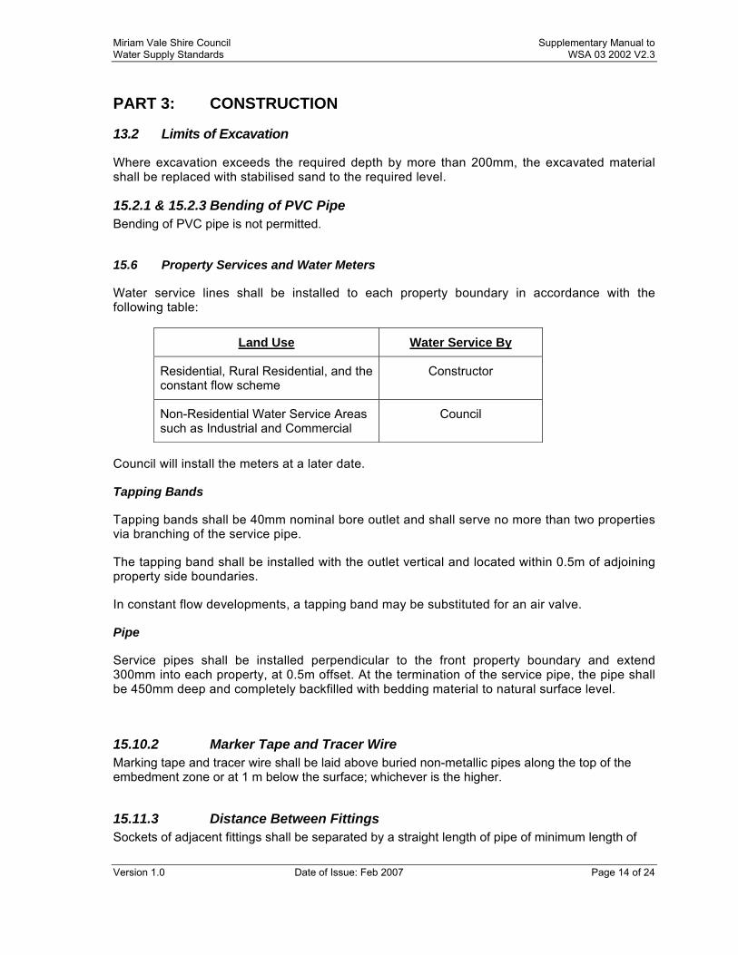
15.6 Property Services and Water Meters
Water service lines shall be installed to each property boundary in accordance with the following table:
Land Use Water Service By
Residential, Rural Residential, and the constant flow scheme
Constructor
Non-Residential Water Service Areas such as Industrial and Commercial
Council
Council will install the meters at a later date.
Tapping Bands
Tapping bands shall be 40mm nominal bore outlet and shall serve no more than two properties via branching of the service pipe.
The tapping band shall be installed with the outlet vertical and located within 0.5m of adjoining property side boundaries.
In constant flow developments, a tapping band may be substituted for an air valve.
Pipe
Service pipes shall be installed perpendicular to the front property boundary and extend 300mm into each property, at 0.5m offset. At the termination of the service pipe, the pipe shall be 450mm deep and completely backfilled with bedding material to natural surface level.
15.10.2 Marker Tape and Tracer Wire Marking tape and tracer wire shall be laid above buried non-metallic pipes along the top of the embedment zone or at 1 m below the surface; whichever is the higher.
15.11.3 Distance Between Fittings Sockets of adjacent fittings shall be separated by a straight length of pipe of minimum length of
Miriam Vale Shire Council Supplementary Manual to Water Supply Standards WSA 03 2002 V2.3
Version 1.0 Date of Issue: Feb 2007 Page 15 of 24
500 mm.
16.2 Embedment Material Embedment material for water mains and water services shall be 5 to 7 mm single sized aggregate. This is considered to be self compacting.
16.3.1 Compaction of Embedment – Methods Flooding compaction is not permitted.
16.3.2 Compactions Trials The pre-qualification of embedment compaction method shall not be used as an alternative to compaction testing.
17.1.2 Trench Filling-Material Requirements Trench filling material shall consist of the best material from the trench excavation, free from organic matter, with particle size not exceeding 75mm and can achieve the required compaction. A layer of geo-fabric is to be placed between the embedment material and backfill material. For trenches in the roadways and footpaths, fill material shall be in accordance with the requirements of the road owner.
18 Swabbing Swabbing is not required.
19.3.4 Trench Fill Compaction Testing The Contractor shall be responsible for all compaction testing and shall arrange for the testing to be carried out by a NATA certified Test Laboratory. Prior to commencing work the Contractor shall prepare a testing plan showing the number of tests and depths in each zone where tests are to be carried out. The Laboratory shall randomly select test locations in each zone. The Water Agency may direct the Laboratory to undertake additional tests in any zone. The test locations shall be uniformly distributed over the works. Test Frequency Testing shall not be clustered within a zone or at boundaries of a zone. In deep trenches where more than 1 layer is to be tested, the test locations shall, where practicable, be staggered from those layers above or below by at least 5 m for water mains and 2 m for water services. Compaction Certificates Prior to the issue of the Certificate of Practical Completion, the Contractor shall submit the individual compaction test records and a Certificate of Compliance from the NATA Test Laboratory confirming that the tests have been completed in accordance with the testing plan and that the specified compaction has been achieved.
Miriam Vale Shire Council Supplementary Manual to Water Supply Standards WSA 03 2002 V2.3
Version 1.0 Date of Issue: Feb 2007 Page 16 of 24
Non-Compliance of Compaction testing If the compaction tests fail, the Contractor shall remove and re-compact the fill from all areas that fail the test. The compaction tests shall be repeated at the Contractors’ cost until satisfactory compaction levels are achieved.
19.4.1 Pressure Testing – General Testing shall include water services and stop cocks.
19.4.2 System Test Pressure The test pressure shall be 1200 kPa applied as close as practicable to the lowest point of the main.
19.4.3 Maximum allowable loss No water loss is permitted over a 15 minute period at the test pressure.
19.4.4 Pressure Test Procedure
All Pressure Testing in accordance with AS 2566.2
19.5 Bacteriological Test Council shall undertake bacteriological testing on all new mains and charge the Contractor a fee for the service. Should the bacteriological test fail twice, the Contractor shall disinfect the mains at his cost.
19.5.3 Satisfactory Bacteriological Test The acceptable range for the heterotrophic count shall be 0 – 100 cfu/mL
20.1 Disinfection – General The disinfection agent shall be a sodium hypochlorite solution or other approved chlorine bearing agent. The dosing rate shall be 20 mg/L with a contact time of 24 hours. The agent shall be added as a water solution to the chlorination point immediately downstream of the stop valve, where the new main connects to the existing main.
22.1 Connections to Existing Mains All works on the existing reticulation system shall be considered as “live works” and will be constructed by Council at the Contractors cost. The installation details shall comply with Section 4.7 of this document.
23.1 Restoration, General - Add
Restoration shall be carried out progressively as each section of the Works is completed.
Miriam Vale Shire Council Supplementary Manual to Water Supply Standards WSA 03 2002 V2.3
Version 1.0 Date of Issue: Feb 2007 Page 17 of 24
The excavated and disturbed area shall be stabilised to minimise wind and water erosion of the restored area.
24 Work As-Constructed Details
Recording and certification of “As-Constructed” works shall comply with Section 7.3 of this document

Miriam Vale Shire Council Supplementary Manual to Water Supply Standards WSA 03 2002 V2.3
Version 1.0 Date of Issue: Feb 2007 Page 18 of 24
PART 4 STANDARD DRAWINGS
The following table indicates the appropriate use of WSCOA standard drawings
Status of WSCOA Drawings is per the following key.
Use Use as Miriam Vale Shire Council standard practice (with amendment if necessary as indicated in the Table below)
Not to be Used The WSCOA drawing is not to be used for design or construction purposes.
Topic WSCOA
Drawing WSCOA Status
PIPELINE LAYOUT
Design Layouts, Typical Locality Plan WAT-1100
Design Layouts, Typical Site Plan WAT-1101 IMEAQ Std Drwg R-1010
Typical Mains Construction, Reticulation Main Arrangement
WAT-1102 Thrust blocks shall comply with WAT- 1205, WAT-1206 and WAT-1207. Direct tapping of mains is not permitted. All nuts and bolts to be 316 stainless steel
Typical Mains Construction, Distribution and Transfer Mains
WAT-1103 GRP and steel mains not approved
Typical Mains Construction, DN63 PE Cul-de-sac Arrangement
WAT-1104 Maximum No of connections – 8 Maximum length of PE main – 40 m.
Typical Mains Construction, Connection to Existing Mains
WAT-1105
Property Services, Single Service Main to Meter WAT-1106
Property Services, Split Service Main to Meter WAT-1107
Property Services, Connection to Main WAT-1108

Miriam Vale Shire Council Supplementary Manual to Water Supply Standards WSA 03 2002 V2.3
Version 1.0 Date of Issue: Feb 2007 Page 19 of 24
Property Services, Above Ground Meter Assembly Arrangement
WAT-1109 Tracer wire and marker tape required on non-metallic service connections
EMBEDMENT / TRENCHFILL AND RESTRAINTS
Soil Classification Guidelines and Allowable Bearing Pressures for Anchors and Thrust Blocks
WAT-1200
Embedment & Trenchfill, Typical Arrangement WAT-1201
Standard Embedment, All Pipe Types WAT-1202
Special Embedment, Inadequate and Poor Foundation WAT-1203 Not adopted
Special Embedment, Concrete, Geotextile and Cement Stabilised Systems
WAT-1204
Thrust Block Details, Concrete Blocks WAT-1205 Minimum Factor of Safety of 2.5 for design of blocks
Thrust Blocks Details, Timber and Recycled Plastic Blocks
WAT-1206 Timber and recycled plastic thrust blocks are only acceptable for temporary works.
Thrust and Anchor Blocks, Gate Valves and Vertical Bends
WAT-1207
Restrained Joint System, DN100 to DN375 Mains WAT-1208 Water Agency approval required for use of restrained joint systems.
Trench Drainage, Bulkheads and Trench Stops WAT-1209
Trench Drainage, Typical Systems WAT-1210 Refer to comments for WAT-1209 Granular trench bedding drainage to be discharged to drainage lines at all low points along alignment.
Buried Crossings, Under Obstructions WAT-1211 Place scour bend immediately before first bend where the main deflects under
Miriam Vale Shire Council Supplementary Manual to Water Supply Standards WSA 03 2002 V2.3
Version 1.0 Date of Issue: Feb 2007 Page 20 of 24
the creek
Buried Crossings, Major Roadways WAT-1212 Subject to Water Agency endorsement
Buried Crossings, Railways WAT-1213
Buried Crossings, Bored & Jacked Encasing Pipe Details
WAT-1214
INSTALLATION PRACTICES / STRUCTURES
Valve & Hydrant Identification, Identification and marker Posts
WAT-1300
Typical Valve & Hydrant Installation, Valve Arrangement WAT-1301
Typical Valve & Hydrant Installation, Hydrants and Air Relief Valves
WAT-1302 Air Vent to be 100 SHS with pressed steel cap, SS insect gauze. Water Agency to provide details.
Typical Surface Fitting Installation, Gate Valve Surface Boxes, Non Trafficable
WAT-1303
Typical Surface Fitting Installation, Gate Valve Surface Boxes, Trafficable
WAT-1304
Typical Surface Fitting Installation, Hydrant Surface Boxes Trafficable
WAT-1305
Typical Appurtenance Installation, Scour Arrangements WAT-1307
Typical Appurtenance Installation, Valve Chambers WAT-1308
Typical Appurtenance Installation, Pressure Reducing Valves
WAT-1309
Aerial Crossings, Aqueduct WAT-1310
Aerial Crossings, Aqueduct Protection Grille WAT-1311
Aerial Crossings, Bridge Crossing Concepts WAT-1312
Flanged Joints WAT-1313
FABRICATION DETAILS
Typical Steel Pipe Jointing, Butt Welding of Joints WAT-1400
Typical Steel Pipe Jointing, Rubber Ring Joint Spigot Bands
WAT-1401
Typical Steel Pipe Jointing, Welding Pipe Collars WAT-1402
Miriam Vale Shire Council Supplementary Manual to Water Supply Standards WSA 03 2002 V2.3
Version 1.0 Date of Issue: Feb 2007 Page 21 of 24
Typical Steel Fabrication, Bends WAT-1403
Typical Steel Fabrication, Access Openings for Pipes ≥ DN750
WAT-1404
Typical Steel Fabrication, Dismantling and Flexible Joints
WAT-1405
Typical Steel Fabrication, Valve Connection Bypass WAT-1406
DI Installation, Valve Bypass Arrangement DI and GRP Pipe
WAT-1407
Joint Corrosion Protection, Cement Mortar Lined Steel Pipe DN300 to DN1200
WAT-1408
Hydrant Installation Fittings WAT-1409
Miriam Vale Shire Council Supplementary Manual to Water Supply Standards WSA 03 2002 V2.3
Version 1.0 Date of Issue: Feb 2007 Page 22 of 24
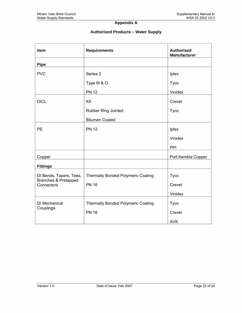
Appendix A
Authorised Products – Water Supply
Item Requirements Authorised Manufacturer
Pipe
PVC Series 2
Type M & O
PN 12
Iplex
Tyco
Vinidex
DICL K9
Rubber Ring Jointed
Bitumen Coated
Crevet
Tyco
PE PN 12 Iplex
Vinidex
PPI
Copper Port Kembla Copper
Fittings
DI Bends, Tapers, Tees, Branches & Pretapped Connectors
Thermally Bonded Polymeric Coating
PN 16
Tyco
Crevet
Vinidex
DI Mechanical Couplings
Thermally Bonded Polymeric Coating
PN 16
Tyco
Crevet
AVK
Miriam Vale Shire Council Supplementary Manual to Water Supply Standards WSA 03 2002 V2.3
Version 1.0 Date of Issue: Feb 2007 Page 23 of 24
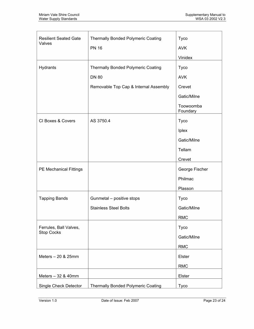
Resilient Seated Gate Valves
Thermally Bonded Polymeric Coating
PN 16
Tyco
AVK
Vinidex
Hydrants Thermally Bonded Polymeric Coating
DN 80
Removable Top Cap & Internal Assembly
Tyco
AVK
Crevet
Gatic/Milne
Toowoomba Foundary
CI Boxes & Covers AS 3750.4 Tyco
Iplex
Gatic/Milne
Tellam
Crevet
PE Mechanical Fittings George Fischer
Philmac
Plasson
Tapping Bands Gunmetal – positive stops
Stainless Steel Bolts
Tyco
Gatic/Milne
RMC
Ferrules, Ball Valves, Stop Cocks
Tyco
Gatic/Milne
RMC
Meters – 20 & 25mm Elster
RMC
Meters – 32 & 40mm Elster
Single Check Detector Thermally Bonded Polymeric Coating Tyco
Miriam Vale Shire Council Supplementary Manual to Water Supply Standards WSA 03 2002 V2.3
Version 1.0 Date of Issue: Feb 2007 Page 24 of 24
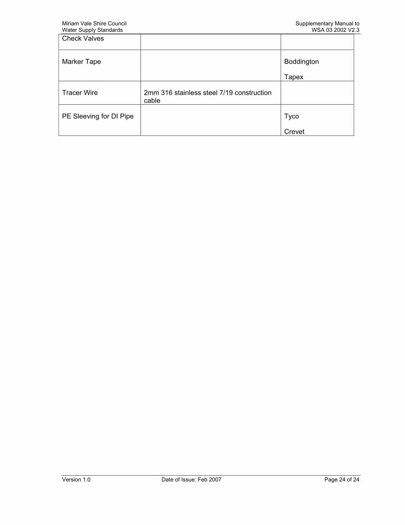
Check Valves
Marker Tape Boddington
Tapex
Tracer Wire 2mm 316 stainless steel 7/19 construction cable
PE Sleeving for DI Pipe Tyco
Crevet