Embed Size (px)
Citation preview
NDIA08 Overview 5/21/2012 1 www.peostri.army.mil/PM-ITTS/TMO NDIA08 Overview 5/21/2012 1
NDIA 2012
Missile Simulation in Support of Research, Development, Test Evaluation and Acquisition
15 May 2012
Briefed by: Stephanie Brown Reitmeier
United States Army Aviation and Missile Research, Development, and Engineering Center
CLEARED FOR PUBLIC RELEASE

NDIA08 Overview 5/21/2012 2 www.peostri.army.mil/PM-ITTS/TMO
Pre and Post Test Flight Construction
Live Fire Pre and Post Flight Reconstruction
Simulations are used after flight to make determinations about performance. These data may also be used for verification purposes.
The use of models in these simulations allow for scenario excursion and robust treatment of the exercise.
Live tests are costly. Simulations are used in advance of the flight to simulate expected conditions. This information may be used to make adjustments or recommendations prior to test.

NDIA08 Overview 5/21/2012 3 www.peostri.army.mil/PM-ITTS/TMO
All Digital Simulation - Used to analyze and visualize system
performance from launch to target interception
- Models are incorporated into the simulation and the loop is “closed”
Sensor and System Performance Verification
Sensor and System Performance Assessments
Hardware in the Loop - Used to assess system performance using actual system hardware as well as software
- Models are presented to the system

NDIA08 Overview 5/21/2012 4 www.peostri.army.mil/PM-ITTS/TMO
All Digital Simulation
The Common Scene Generator in compilation with a system IFS gives designers the capability to do numerous “what if” excursions during development The incorporation of validated models to the Common Scene Generator makes it a useful tool in preparation for formal developmental and operational test exercises The simulation, along with its component models, are generally accredited for use in supporting developmental and operational test activities

NDIA08 Overview 5/21/2012 5 www.peostri.army.mil/PM-ITTS/TMO
Sensor Models
Tracker Models
6-DOF Propulsion
Aerodynamics Controls & Kinematics
Scene Generation
An Integrated Flight Simulation (IFS) is characterized by the integration of highly detailed component models, high-fidelity synthetic image generation for stimulation of tracking algorithms, and inclusion of embedded tactical flight software. Integrated flight simulation
extends traditional 6-DOF with:
Tactical GNC
Tactical Track Algorithms
High Fidelity Sensor Models
High Fidelity Scene Generation
Sensor and System Performance Verification
All Digital Integrated Flight Simulation

NDIA08 Overview 5/21/2012 6 www.peostri.army.mil/PM-ITTS/TMO
Env Effects
Env Effects
Laser Spot
IR
MMW
SAL
Scene Generator High Fidelity Models Sensor Models
Antenna /Radome
- High Fidelity Scene Generation -Targets - Clutter - Range Gates - Countermeasures - Atmosphere - Weather
Common Scene Generator (CSG) IR
Optics, MTF, NEDT, Readout Electronics
MMW Antenna, Waveform Generation, Pulse Compression, RF electronics
SAL Dome/Optics/Detector, Analog Electronics, Time Resolved Pulse
Tactical Code
Tact
ical
Sof
twar
e an
d Fi
rmw
are
Sensor Development and Sensor and System Performance Verification
Scene Flow Diagram

NDIA08 Overview 5/21/2012 7 www.peostri.army.mil/PM-ITTS/TMO
Sensor and System Performance Verification
All Digital CSG Overview
The Common Scene Generator (CSG) calculates the energy in the environment that is presented at the seeker dome over the waveband of a given seeker.
– Infrared (IR) • Calculates either blackbody equivalent
temperature (degrees Kelvin), radiance (W/cm2/sr), or photon radiance (ph/s/cm2/sr) based on emitted and reflected energy in the environment.
– Semi-Active Laser (SAL) • Calculates the energy density in Joules/cm2
based on energy emitted by a designator that reflects or scatters back toward the sensor.
– Millimeter Wave (MMW) • Calculates the energy return from clutter and
targets based on geometry, radar antenna and waveform characteristics and presents to the sensor in complex I/Q samples (volts).
– GroundTruth • Generates an image color-coded by pixel for
target, background and obscured target – Visual
• Renders terrain and objects with no spectral calculations

NDIA08 Overview 5/21/2012 8 www.peostri.army.mil/PM-ITTS/TMO
IR Mesh
RF Facetized
Data Collection
Visualization Model
Gather physical target information for accurate CAD representation
Use dimensional data to create very high fidelity target geometries suitable for use for RF prediction software
High fidelity model is used as a starting point to create meshes that are inputs to IR predictive software
High fidelity model is used as a starting point to create low fidelity models used training and visual simulators
The process begins through the creation of high-fidelity geometries
Geometry Development Process

NDIA08 Overview 5/21/2012 9 www.peostri.army.mil/PM-ITTS/TMO
Facetized Model
Meshed Model
Infrared and Semi Active Laser Textures, Temperature or Radiance
Infrared
Signature Software
Radio Frequency Signature Software
Additional processing is needed to generate physics based
inputs for simulations
Radio Frequency Back Scatter, Azimuth and Elevation Dependent
Simulation Inputs are Created Predictively

NDIA08 Overview 5/21/2012 10 www.peostri.army.mil/PM-ITTS/TMO
Virtual Targets are vetted through a validation process to: Ensure geometric fidelity Ensure physical and spectral accuracy
Validation

NDIA08 Overview 5/21/2012 11 www.peostri.army.mil/PM-ITTS/TMO
An Example
A customer has a requirement to test system performance against a particular set of vehicles in a location in the United States. Said customer would like to have an analysis of the test scenarios before actually flying the hardware. Let us choose our locations to be: Eglin Air force Base, Florida

NDIA08 Overview 5/21/2012 12 www.peostri.army.mil/PM-ITTS/TMO
Background
AMRDEC has established a methodology to create high-fidelity terrain backgrounds in which to utilize virtual targets This methodology involves: 1. The identification of the area of interest 2. The identification of discrete clutter types 3. Prediction of the environment using an Infrared tool known as
EOVIEW 4. Methodical data collection of Radar data of the discrete clutter
types 5. Scene creation in CSG 6. Insertion of virtual targets 7. Simulation is run for both Radar and Infrared in CSG with targets
and backgrounds

NDIA08 Overview 5/21/2012 13 www.peostri.army.mil/PM-ITTS/TMO
The identification of the area of interest Class Map Example

NDIA08 Overview 5/21/2012 14 www.peostri.army.mil/PM-ITTS/TMO
Terrain Characterization and Model Development Process
Material Classification Process
DEM RESAMPLE PROCESS
Source Data •Satellite Imagery •Aerial Survey Photos
Object Placement Map (OPM) Derivation Process
South Iraq Multi-Spectral Ortho
Mosaic
South Iraq Source DEM
Class Map
Clutter discrete locations Vegetation Height
Ground Plane FTOP
NDIA08 Overview 5/21/2012 15 www.peostri.army.mil/PM-ITTS/TMO
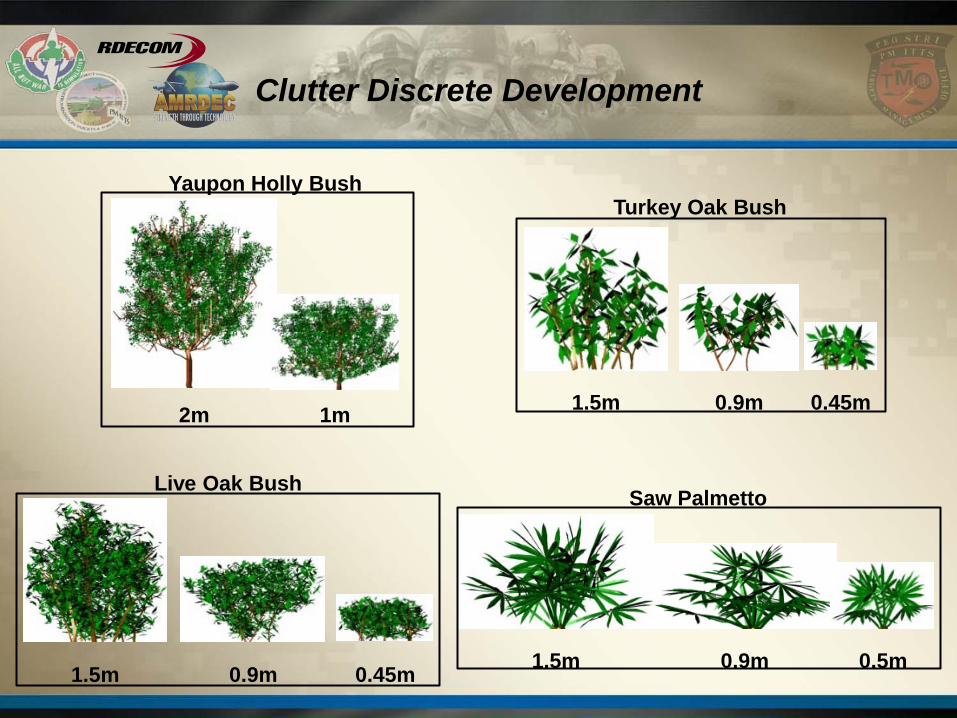
Clutter Discrete Development
Yaupon Holly Bush
2m 1m 0.45m 0.9m 1.5m
Turkey Oak Bush
1.5m 0.9m 0.45m
Live Oak Bush
1.5m 0.9m 0.5m
Saw Palmetto

NDIA08 Overview 5/21/2012 16 www.peostri.army.mil/PM-ITTS/TMO
IR Terrain Signature Calculation Process
Class Map Topo Data (FTOP)
Thermal Solver
Modeled LWIR - Clear Yuma Day
320
340
360
380
400
420
440
460
0:00 2:00 4:00 6:00 8:00 10:00 12:00 14:00 16:00 18:00 20:00 22:00 0:00
Time of Day - June 29, 1992
Lo
ng
Wa
ve
Ra
dia
tio
n (
W/m
2)
0
10
20
30
40
50
60
Re
lati
ve
Hu
mid
ity
(%
)
Weather Data Material
Properties for Each
Class • Absorptivity • Emissivity • Thermal Conductivity • Specific Heat • Etc.
Scene Components
Build OPM
Physical Temperatures Target Terrain
Clutter Discretes
Virtual Target
CSG Thermal Signature Inputs
FRAD BIFS

NDIA08 Overview 5/21/2012 17 www.peostri.army.mil/PM-ITTS/TMO
EOView Results - Thermal Interactions with VirtualTarget Model

NDIA08 Overview 5/21/2012 18 www.peostri.army.mil/PM-ITTS/TMO
Radar Signature Data Collection
Portable radar collection asset Ka-band 2GHz Bandwidth 1.8m rail ~110’ height extension
Rail-SAR

NDIA08 Overview 5/21/2012 19 www.peostri.army.mil/PM-ITTS/TMO
Radar Measurement Process
Mark the exact clutter scene of interest with ground truth net (10’x 10’) Set removable trihedral markers at the corners of the net Remove net

NDIA08 Overview 5/21/2012 20 www.peostri.army.mil/PM-ITTS/TMO
Measure Clutter: with indexing
View from the RAILSAR camera Index reflectors in-scene Motion compensation reflector in-scene

NDIA08 Overview 5/21/2012 21 www.peostri.army.mil/PM-ITTS/TMO
Grass Data:10deg Elevation
-8-6-4-202468
-8
-6
-4
-2
0
2
4
6
8
10

NDIA08 Overview 5/21/2012 22 www.peostri.army.mil/PM-ITTS/TMO
Live Oak, 30 deg Elevation

NDIA08 Overview 5/21/2012 23 www.peostri.army.mil/PM-ITTS/TMO
Live Oak, 30deg Elevation
-8-6-4-202468
-10
-8
-6
-4
-2
0
2
4
6
8
10

NDIA08 Overview 5/21/2012 24 www.peostri.army.mil/PM-ITTS/TMO
Radar CSG Demonstration Pictures
NDIA08 Overview 5/21/2012 25 www.peostri.army.mil/PM-ITTS/TMO
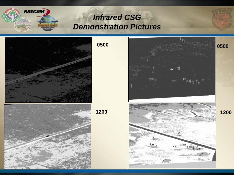
Infrared CSG Demonstration Pictures
0500 0500
1200 1200

NDIA08 Overview 5/21/2012 26 www.peostri.army.mil/PM-ITTS/TMO
Infrared Demonstration: Moving Virtual Target

NDIA08 Overview 5/21/2012 27 www.peostri.army.mil/PM-ITTS/TMO
Infrared Demonstration: Moving Virtual Target
NDIA08 Overview 5/21/2012 28 www.peostri.army.mil/PM-ITTS/TMO
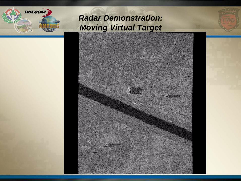
Radar Demonstration: Moving Virtual Target

NDIA08 Overview 5/21/2012 29 www.peostri.army.mil/PM-ITTS/TMO
Virtual Targets Center

NDIA08 Overview 5/21/2012 30 www.peostri.army.mil/PM-ITTS/TMO
Summary