Embed Size (px)
Citation preview

QUALCOMM19/27/2005
Mixed-signal Modeling Using Simulink based-C
Shoufeng Mu, Michael Laisne

QUALCOMM29/27/2005
Agenda
Objectives of Mixed-signal (MS) modeling
Advantages of Simulink based MS modeling
Simulink based MS modeling flow
1) Build a simulink model
2) Convert the Simulink model to C code
3) Integrate C model with HDL
4) HDL wrappers
Automation scripts
Integration and Simulation
Summary

QUALCOMM39/27/2005
Objectives of Mixed-signal modeling
Provide a solution for a unified chip/system level mixed-signal verification (SOC or SIP)• Verify the digital and mixed-signal design in the same environment• Verify the mixed-signal interface between digital and analog dies • Initiate verification and debug processes earlier to find out design/testability
issues before tape-out
Provide a behavioral model for the analog/mixed-signal block before the design is ready• More often the mixed-signal/analog block is the bottleneck.
Enable efficient post silicon mixed-signal test pattern development and verification• Can provide a robust environment for the mixed-signal pattern development• Test pattern verification before 1st Silicon arrival• ATE timing verification

QUALCOMM49/27/2005
Simulink Based MS Model Development
Simulink Model Development
System Spec &
Analog Design SIMULINK
Simulink Model Verification
C-Models Generation
HDL and C-Models Integration (HDL wrapper)
Real Time Workshop
ModelSim/ADMS
Analog/MS transistor level
design
Model Certification

QUALCOMM59/27/2005
Traditional Mixed signal modeling and verification
• Traditional mixed-signal verification– Separate simulation environments– Partition the ASIC by Analog-Digital boundary– Leave holes in the signal interact between analog and digital
blocks
• Mixed-signal behavioral model– C model– VHDL-AMS/Verilog-AMS– Verilog-A
QUALCOMM69/27/2005
Advantages of Simulink based MS modeling
• Simulink is a tool for system level modeling and simulation.• Continuous, discrete and hybrid simulation• Simulations are interactive, so you can change the parameters
on the fly and immediately see the results.• Integration with Matlab, Extension, Blocksets and Toolboxes.• C code is automatically generated by using RTW• Can be easily integrated with Verilog/VHDL digital simulation
environment• No special requirements on the simulator

QUALCOMM79/27/2005
Build the Simulink model
Convert Simulink model to c code using RTW
Add FLI in C to interface with VHDLor PLI to interface with Verilog and generate exe
Create VHDL /Verilog wrappers
Simulink Based MS Modeling Flow

QUALCOMM89/27/2005
Build the Simulink Model (1)Example of Simulink Model
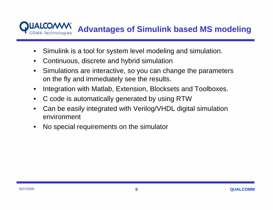
• Build a simple one bit A2D converter using Simulink
DoutVref
Rsh
Csh
Vin
L_clk
-
En_out
+
D-latch
Tristate buffer
sample

QUALCOMM99/27/2005
Build the Simulink Model (2)A2d1bit Top Level
QUALCOMM109/27/2005
Build the Simulink Model (3)A2d1bit submodel

QUALCOMM119/27/2005
Build the Simulink Model (4)A2d1bit Sample hold model

QUALCOMM129/27/2005
Build the Simulink Model (5)Behavioral model of Mash22 SD Modulator

QUALCOMM139/27/2005
Build the Simulink Model (6)Behavioral model of Programmable RC Filter

QUALCOMM149/27/2005
Convert Simulink Model To C Code using RTW (Real Time Workshop)
Procedures to generate C code using Real Time Workshop
• Stop time under the "solver" tab in the Simulation Parameter window should be "inf" for infinite
• The type of the solver options in the simulation Parameter window should be fixed-step
• Make sure the mode is set to single-tasking• Under the Workspace IO tab, make sure everything is unchecked• Under the Real-Time Workshop tab, select Target Configuration to be
Generic Real-Time Target (grt.tlc)• Verify that the "Generate Code is only" button is not selected, then save
your model• In the simulation Parameter window, under the "Real-Time Workshop"
tab, press the "build button"
QUALCOMM159/27/2005
Using FLI To Link C With VHDL(1)
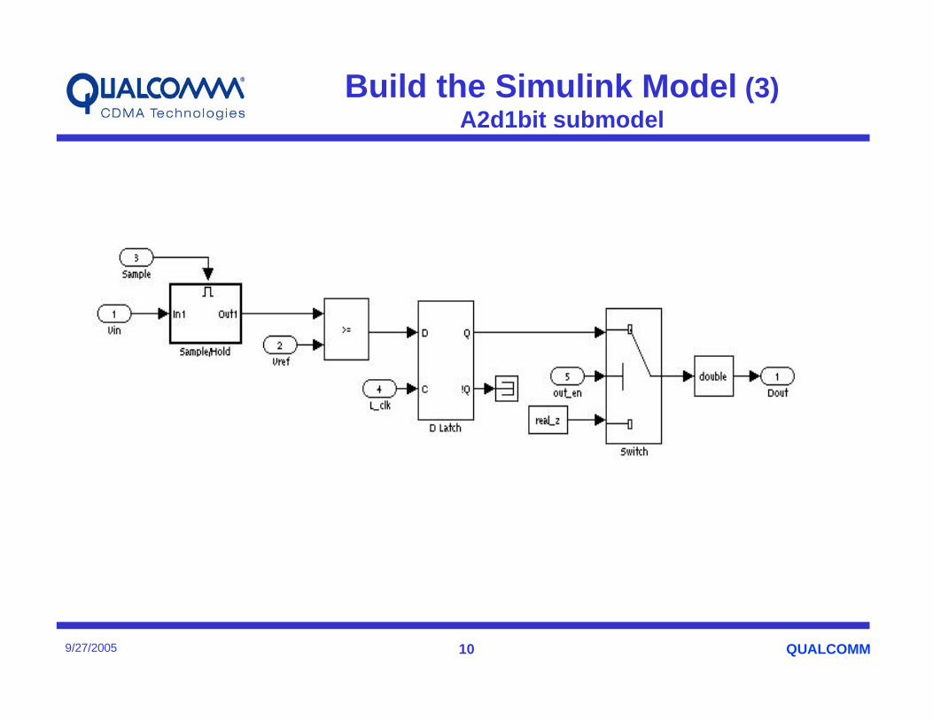
library ieee;use ieee.std_logic_1164.all;entity a2d1bit_0_sub is
port (signal Vin : in real;signal Vref : in real;signal L_clk : in real;signal Out_en : in real;signal sample : in real;signal Dout : out real
);end a2d1bit_0_sub;
architecture one of a2d1bit_0_sub is
attribute foreign : string;attribute foreign of one : architecture is "a2d1bit_0init ./a2d1bit_0.modelsim.so";beginassert false report "Error: Foreign subprogram a2d1bit not called." severity error;
end architecture one;

QUALCOMM169/27/2005
Using FLI to link C with VHDL(2)
The following Figure illustrates partitioning of the C main function and VHDL entity and architecture
C main file (grt_maim.c)
a2d1bit_0rt_OneStep() {
/*get the value from VHDL input ports/*execute functionality /*drives value onto VHDL output ports/*sensitize or wakeup call
}
a2d1bit_0init() { /*memory allocation /*connect to VHDL ports /*sensitize or wakeup call }
architecture one of a2d1bit_0_sub isattribute foreign : string;
attribute foreign of one : architecture is"a2d1bit_0init ./a2d1bit_0.modelsim.so“
end architecture one;
entity a2d1bit_0_sub is port (signal Vin : in real;signal Vref : in real;signal L_clk : in real;signal Out_en : in real;
signal Dout : out real );end a2d1bit_0_sub;

QUALCOMM179/27/2005
VHDL Wrappers (1)
Vin(real)
Vref(real)
L_clk(std_logic)
Out_en(std_logic)
Vin(real)
Out_en(real)
L_clk(real)
Vref(real) Dout (real)Dout (std_logic)
outer wrapper
Inner wrapper

QUALCOMM189/27/2005
VHDL Wrappers (2)
• There are two wrappers for the C model
• The “inner” wrapper has real inputs and outputs only, and its architecture calls the C library with a foreign attribute
• The “outer” wrapper takes care of the conversion of the data format, as well as separating the bits in a digital bus. The name and data type of input/output ports of the “outer” wrapper should exactly match the pin name of the analog schematic. The “inner” layer can have different number of output pins for debugging purpose.

QUALCOMM199/27/2005
Automation scripts
• C code generation, customization and writing VHDL wrappers can be automated by Perl/shell scripts
Matlab automation script for C code generation
Perl scripts to generate the compile scripts which support different platform
Perl scripts to customize code
Perl script to generate the VHDL wrappers

QUALCOMM209/27/2005
Integration and Simulation results
• Can be easily integrated with digital design (VHDL or Verilog)
•Can be simulated with digital or mixed-signal simulator
• we successfully integrated the Broad-receiver, Wide Band CODEC, House-keeping ADC, PLLs, TXDAC, etc into our digital simulation environment, and got reasonable simulation results.

QUALCOMM219/27/2005
Summary
• The Simulink based C models can be certified with transistor level designs
• With automation scripts, the development cycle of Simulinkbased C approach is short
• The Simulink based C models can be easily integrated with VHDL or Verilog design
• The Simulink based C models can be simulated with digital or mixed-signal simulator
• With Simulink based C models, we can achieve true chip level or system level mixed-signal verification.


![HMO2024 - SOS · [HMO2024] HMO1522 [HMO1524], Mixed Signal Mixed Signal 2](https://img.pdfslide.net/doc/110x75/606a26e1cd05047284562add/hmo2024-sos-hmo2024-hmo1522-hmo1524-mixed-signal-mixed-signal-2.jpg)