Embed Size (px)
Citation preview
REFERENCEMANUAL
2002
MIXER / MICROPHONE PREAMPLIFIER

Important Safety Instructions

Important Safety Instructions
Important Safety Instructions (English) Safety symbols used in this product
This symbol alerts the user that there are important operating and maintenance instructions in the literature accompanying this unit.
This symbol warns the user of uninsulated voltage within the unit that can cause dangerous electric shocks.
This symbol warns the user that output connectors contain voltages that can cause dangerous electrical shock. Please follow these precautions when using this product: 1. Read these instructions. 2. Keep these instructions. 3. Heed all warnings. 4. Follow all instructions. 5. Do not use this apparatus near water. 6. Clean only with a damp cloth. Do not spray any liquid cleaner
onto the faceplate, as this may damage the front panel controls or cause a dangerous condition.
7. Install in accordance with the manufacturer's instructions. 8. Do not install near any heat sources such as radiators, heat
registers, stoves, or other apparatus (including amplifiers) that produce heat.
9. Do not defeat the safety purpose of the polarized or grounding-type plug. A polarized plug has two blades with one wider than the other. A grounding-type plug has two blades and a third grounding prong. The wide blade or the third prong are provided for your safety. When the provided plug does not fit into your outlet, consult an electrician for replacement of the obsolete outlet.
10. Protect the power cord from being walked on or pinched, particularly at plugs, convenience receptacles, and the point where they exit from the apparatus.
11. Use only attachments or accessories specified by the manufacturer.
Important Safety Instructions
12. Use only with a cart, stand, bracket, or table designed for use with professional audio or music equipment. In any installation, make sure that injury or damage will not result from cables pulling on the apparatus and its mounting. If a cart is used, use caution when moving the cart/apparatus combination to avoid injury from tip-over.
13. Unplug this apparatus during lightning storms or when unused for long periods of time.
14. Refer all servicing to qualified service personnel. Servicing is required when the apparatus has been damaged in any way, such as when the power-supply cord or plug is damaged, liquid has been spilled or objects have fallen into the apparatus, the apparatus has been exposed to rain or moisture, does not operate normally, or has been dropped.
15. This unit produces heat when operated normally. Operate in a well-ventilated area with at least six inches of clearance from peripheral equipment.
16. This product, in combination with an amplifier and headphones or speakers, may be capable of producing sound levels that could cause permanent hearing loss. Do not operate for a long period of time at a high volume level or at a level that is uncomfortable. If you experience any hearing loss or ringing in the ears, you should consult an audiologist.
17. Do not expose the apparatus to dripping or splashing. Do not place objects filled with liquids (flower vases, soft drink cans, coffee cups) on the apparatus.
18. WARNING: To reduce the risk of fire or electric shock, do not expose this apparatus to rain or moisture.
Important Safety Instructions
Instructions de Sécurité Importantes (French) Symboles utilisés dans ce produit
Ce symbole alèrte l’utilisateur qu’il existe des instructions de fonctionnement et de maintenance dans la documentation jointe avec ce produit.
Ce symbole avertit l’utilisateur de la présence d’une tension non isolée à l’intérieur de l’appareil pouvant engendrer des chocs électriques.
Ce symbole prévient l'utilisateur de la présence de tensions sur les raccordements de sorties, représentant un risque d'électrocution. Veuillez suivre ces précautions lors de l’utilisation de l’appareil: 1. Lisez ces instructions. 2. Gardez ces instructions. 3. Tenez compte de tous les avertissements. 4. Suivez toutes les instructions. 5. N’utilisez pas cet allareil à proximité de l’eau. 6. Ne nettoyez qu’avec un chiffon humide. Il est potentiellement
dangereux d'utiliser des pulvérisateurs ou nettoyants liquides sur cet appareil.
7. Installez selon les recommandations du constructeur. 8. Ne pas installer à proximilé de sources de chaleur comme
radiateurs, cuisinière ou autre appareils (don’t les amplificateurs) produisant de la chaleur.
9. Ne pas enlever la prise de terre du cordon secteur. Une prise murale avec terre deux broches et une troisièrme reliée à la terre. Cette dernière est présente pour votre sécurité. Si le cordon secteur ne rentre pas dans la prise de courant, demandez à un électricien qualifié de remplacer la prise.
10. Evitez de marcher sur le cordon secteur ou de le pincer, en particulier au niveau de la prise, et aux endroits où il sor de l’appareil.
11. N’utilisez que des accessoires spécifiés par le constructeur.
Important Safety Instructions
Suite de la page suivante 12. N’utilisez qu’avec un stand, ou table conçus pour l’utilisation
d’audio professionnel ou instruments de musique. Dans toute installation, veillez de ne rien endommager à cause de câbles qui tirent sur des appareils et leur support.
13. Débranchez l’appareil lors d’un orage ou lorsqu’il n’est pas utilisé pendant longtemps.
14. Faites réparer par un personnel qualifié. Une réparation est nécessaire lorsque l’appareil a été endommagé de quelque sorte que ce soit, par exemple losrque le cordon secteur ou la prise sont endommagés, si du liquide a coulé ou des objets se sont introduits dans l’appareil, si celui-ci a été exposé à la pluie ou à l’humidité, ne fonctionne pas normalement ou est tombé.
15. Puisque son fonctionement normale génère de la chaleur, placez cet appareil au moins 15cm. des équipments péripheriques et assurez que l’emplacement permet la circulation de l’air.
16. Ce produit, utilisé avec un amplificateur et un casque ou des enceintes, est capable de produite des niveaux sonores pouvant engendrer une perte permanente de l’ouïe. Ne l’utilisez pas pendant longtemps à un niveau sonore élevé ou à un niveau non confortable. Si vous remarquez une perte de l’ouïe ou un bourdonnement dans les oreilles, consultez un spécialiste.
17. N'exposez pas l'appareil à l'égoutture ou à l'éclaboussement. Ne placez pas les objets remplis de liquides (vases à fleur, boîtes de boisson non alcoolique, tasses de café) sur l'appareil.
18. AVERTISSEMENT: Pour réduire le risque du feu ou de décharge électrique, n'exposez pas cet appareil à la pluie ou à l'humidité.

Important Safety Instructions
Lesen Sie bitte die folgende Sicherheitshinweise (German) Sicherheit Symbole verwendet in diesem Produkt
Dieses Symbol alarmiert den Benutzer, daß es wichtige Funktionieren und Wartung Anweisungen in der Literatur gibt, die diese Maßeinheit begleitet.
Dieses Symbol warnt den Benutzer der nicht isolierten Spannung innerhalb der Maßeinheit, die gefährliche elektrische Schläge verursachen kann.
Dieses Symbol warnt den Benutzer, dem Ausgabestecker Spannungen enthalten, die gefährlichen elektrischen Schlag verursachen können. Folgen Sie bitte diesen Vorkehrungen, wenn dieses Produkt verwendet wird: 1. Lesen Sie die Hinweise. 2. Halten Sie sich an die Anleitung. 3. Beachten Sie alle Warnungen. 4. Beachten Sie alle Hinweise. 5. Bringen Sie das Gerät nie mit Wasser in Berührung. 6. Verwenden Sie zur Reinigung nur ein weiches Tuch.
Verwenden Sie keine flüssigen Reinigungsmittel. Dies kann gefährliche Folgen haben.
7. Halten Sie sich beim Aufbau des Gerätes an die Angaben des Herstellers.
8. Stellen Sie das Gerät nich in der Nähe von Heizkörpern, Heizungsklappen oder anderen Wärmequellen (einschließlich Verstärkern) auf.
9. Verfehlen Sie nicht den Zweck des grounging Terminals auf dem Netzstecker. Dieses Terminal wird für Ihre Sicherheit zur Verfügung gestellt.
10. Verlegen Sie das Netzkabel des Gerätes niemals so, daß man darüber stolpern kann oder daß es gequetscht wird.
11. Benutzen Sie nur das vom Hersteller empfohlene Zubehör.

Important Safety Instructions
Fortsetzung auf nächster Seite 12. Verwenden Sie ausschließlich Wagen, Ständer, oder Tische, die
speziell für professionelle Audio- und Musikinstrumente geeignet sind. Achten Sie immer darauf, daß die jeweiligen Geräte sicher installiert sind, um Schäden und Verletzungen zu vermeiden. Wenn Sie einen Rollwagen benutzen, achten Sie darauf, das dieser nicht umkippt, um Verletzungen auszuschließen.
13. Ziehen Sie während eines Gewitters oder wenn Sie das Gerät über einen längeren Zeitraum nicht benutzen den Netzstecher aus der Steckdose.
14. Die Wartung sollte nur durch qualifiziertes Fachpersonal erfolgen. Die Wartung wird notwendig, wenn das Gerät beschädigt wurde oder aber das Stromkabel oder der Stecker, Gegenstände oder Flüssigkeit in das Gerät gelangt sind, das Gerät dem Regen oder Feuchtigkeit ausgesetzt war und deshalb nicht mehr normal arbeitet oder heruntergefallen ist.
15. Dieses Gerät produziert auch im normalen Betrieb Wärme. Achten Sie deshalb auf ausreichende Lüftung mit mindestens 15 cm Abstand von anderen Geräten.
16. Dieses Produkt kann in Verbindung mit einem Verstärker und Kopfhörern oder Lautsprechern Lautstärkepegel erzeugen, die anhaltende Gehörschäden verursachen. Betreiben Sie es nicht über längere Zeit mit hoher Lautstärke oder einem Pegel, der Ihnen unangenehm is. Wenn Sie ein Nachlassen des Gehörs oder ein Klingeln in den Ohren feststellen, sollten Sie einen Ohrenarzt aufsuchen.
17. Setzen Sie den Apparat nicht Bratenfett oder dem Spritzen aus. Plazieren Sie die Nachrichten, die mit Flüssigkeiten (gefüllt werden Blumevases, Getränkdosen, Kaffeetassen) nicht auf den Apparat.
18. WARNING: um die Gefahr des Feuers oder des elektrischen Schlages zu verringern, setzen Sie diesen Apparat nicht Regen oder Feuchtigkeit aus.

Important Safety Instructions
CE Declaration Of Conformity See our website at: http://www.alesis.com FCC Compliance Statement This device complies with Part 15 of the FCC rules. Operation is subject to the following two conditions: (1) This device may not cause harmful interference and (2) this device must accept any interference received, including interference that may cause undesired operation. NOTE: This equipment has been tested and found to comply with the limits for a Class B digital device, pursuant to Part 15 of the FCC Rules. These limits are designed to provide reasonable protection against harmful interference in a residential installation. This equipment generates, uses and can radiate radio frequency energy and, if not installed and used in accordance with the instructions, may cause harmful interference to radio communications. However, there is no guarantee that interference will not occur in a particular installation. If this equipment does cause harmful interference to radio or television reception, which can be determined by turning the equipment off and on, the user is encouraged to try to correct the interference by one or more of the following measures: -- Reorient or relocate the receiving antenna. -- Increase the separation between the equipment and receiver. -- Connect the equipment into an outlet on a circuit different from that to which the receiver is connected. -- Consult the dealer or an experienced radio/TV technician for help.
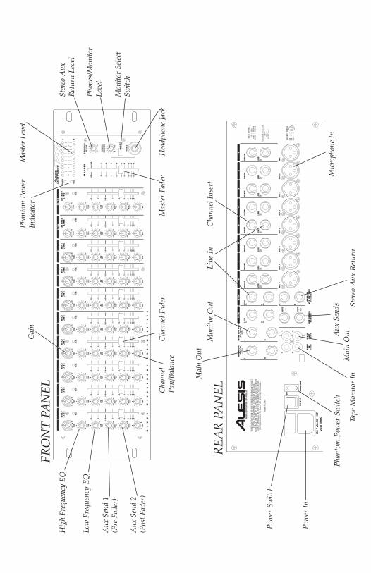
120
5
0-60
HZ5
23W
MAX
Hig
h Fr
eque
ncy
EQ
Low
Fre
quen
cy E
Q
Aux
Sen
d 1
(Pre
Fad
er)
Aux
Sen
d 2
(Pos
t Fad
er)
FRO
NT
PAN
EL
REA
R P
AN
EL
Gai
n
Cha
nnel
Pan/
Bala
nce
Pow
er In
Pow
er S
witc
h
Phan
tom
Pow
er S
witc
hM
ain
Out
Tape
Mon
itor
InSt
ereo
Aux
Ret
urn
Aux
Sen
dsM
icro
phon
e In
Cha
nnel
Fad
er
Mai
n O
ut
Mon
itor
Out
Line
InC
hann
el In
sert
Mas
ter
Leve
lPh
anto
m P
ower
Indi
cato
r
Ster
eo A
uxR
etur
n Le
vel
Phon
es/M
onito
rLe
vel
Mon
itor
Sele
ctSw
itch
Hea
dpho
ne Ja
ckM
aste
r Fa
der
Introduction
Multimix 12R Reference Manual 1
TABLE OF CONTENTS
Table of Contents .................................................................1
Introduction.............................................................................3The Alesis Multimix 12R Microphone Preamplifier/Mixer........................3Using this manual.............................................................................................3Grounding Instructions...................................................................................4
Installation ...............................................................................5Unpacking .........................................................................................................5AC power..........................................................................................................5
Grounding.............................................................................................5Use clean power ...................................................................................6Power switch.........................................................................................6
Mounting...........................................................................................................6
Connections .............................................................................7Inputs .................................................................................................................7
Cable common sense...........................................................................7Microphone Inputs...............................................................................8Phantom power....................................................................................9Line-level devices (synthesizers, CD players, video)....................10TAPE IN jacks .....................................................................................12Phonograph turntables .....................................................................13Do not connect any of the following to any input of theMultimix 12R!......................................................................................13
How to connect effect devices and signal processors...............................14Effects via Aux Send and Aux Return .............................................14In-line processing using the INSERT jacks (compressors &equalizers) ...........................................................................................15
Outputs ............................................................................................................18To a stereo PA system or instrument amplifier ............................18To a mono system..............................................................................18To a stage monitor (foldback) system ............................................18To another mixer................................................................................19To a stereo tape recorder..................................................................19To an ADAT multitrack recorder.....................................................20Phones..................................................................................................23Monitor Out ........................................................................................23
Operating Instructions......................................................25Before turning the mixer on, "zero out' the controls................................25Setting input trim levels ................................................................................26
PEAK LED method ............................................................................26Metering/Unity Gain method..........................................................27
Typical Fader and Control Levels................................................................28Proper gain staging of other equipment........................................29
Introduction
AUX System: Effects Send/Receive............................................................30How to Set Aux Send and Return Levels .......................................30
Using the meter..............................................................................................32Avoiding noise................................................................................................33
System noise (ground loops, hum, induced noise).......................33
Applications...........................................................................37Multitrack recording......................................................................................37
Tracking/Overdubbing.....................................................................37Mixdown..............................................................................................38
Using the HIGH and LOW EQ controls......................................................39Monitoring AUX 1 in the PHONES jack .....................................................40
Troubleshooting...................................................................41Troubleshooting Index..................................................................................41Maintenance/Service.....................................................................................43
Exterior cleaning.................................................................................43
Specifications.......................................................................45Frequency Response......................................................................................45Connectors......................................................................................................45Levels ...............................................................................................................46Impedance.......................................................................................................46Noise performance (typical).........................................................................47Distortion (THD+N).......................................................................................47Power...............................................................................................................47Mounting.........................................................................................................47
Dimensional Drawing .......................................................48
Block diagram .....................................................................49Level diagram.................................................................................................50
Index ........................................................................................51
Introduction
Multimix 12R Reference Manual 3
INTRODUCTIONThe Alesis Multimix 12R MicrophonePreamplifier/Mixer
The Alesis Multimix 12R is a high-quality, rack-mountable 12-input,stereo output audio mixer. It is designed to handle eight microphones,two stereo line inputs, and to route signal to and from external effectprocessing devices. As a basic, easy-to-understand mixer, it can beused in a wide variety of applications from sound reinforcement tomultitrack recording. It may also be used as an accessory or submixerto a larger console.
Using this manualTo get the most out of your Multimix 12R, please read this manual.While the mixer is not complicated to operate, the manual containsinformation that will help you get the highest level of performancefrom it. We’ve included creative alternative techniques that aren'tobvious at first glance.
To find what you need quickly, refer to the index at the back of themanual, or the Table of Contents.
Conventions
The buttons, knobs, and rear panel connectors are referred to in thismanual just as their names appear on the Multimix 12R, using allcapital letters (Example: [TRIM] control, [PAN] knob, [PHONES] jack,etc.).
When something important appears in the manual, an icon (like the one on theleft) will appear in the left margin. This symbol indicates that this informationis vital when operating the Multimix 12R.
Introduction
Grounding InstructionsThis product must be grounded. If it should malfunction or breakdown, grounding provides a path of least resistance for electric currentto reduce the risk of electric shock. This product is equipped with acord having an equipment-grounding conductor and a groundingplug. The plug must be plugged into an appropriate outlet that isproperly installed and grounded in accordance with all local rules andordinances.
DANGER - Improper connection of the equipment-grounding conductorcan result in a risk of electric shock. Check with a qualified electrician orserviceman if you are in doubt as to whether the product is properlygrounded. Do not modify the plug provided with the product; if it will not fitthe outlet, have a proper outlet installed by a qualified electrician.

Introduction
Multimix 12R Reference Manual 3
INTRODUCTIONThe Alesis Multimix 12R MicrophonePreamplifier/Mixer
The Alesis Multimix 12R is a high-quality, rack-mountable 12-input,stereo output audio mixer. It is designed to handle eight microphones,two stereo line inputs, and to route signal to and from external effectprocessing devices. As a basic, easy-to-understand mixer, it can beused in a wide variety of applications from sound reinforcement tomultitrack recording. It may also be used as an accessory or submixerto a larger console.
Using this manualTo get the most out of your Multimix 12R, please read this manual.While the mixer is not complicated to operate, the manual containsinformation that will help you get the highest level of performancefrom it. We’ve included creative alternative techniques that aren'tobvious at first glance.
To find what you need quickly, refer to the index at the back of themanual, or the Table of Contents.
Conventions
The buttons, knobs, and rear panel connectors are referred to in thismanual just as their names appear on the Multimix 12R, using allcapital letters (Example: [TRIM] control, [PAN] knob, [PHONES] jack,etc.).
When something important appears in the manual, an icon (like the one on theleft) will appear in the left margin. This symbol indicates that this informationis vital when operating the Multimix 12R.
Introduction
Grounding InstructionsThis product must be grounded. If it should malfunction or breakdown, grounding provides a path of least resistance for electric currentto reduce the risk of electric shock. This product is equipped with acord having an equipment-grounding conductor and a groundingplug. The plug must be plugged into an appropriate outlet that isproperly installed and grounded in accordance with all local rules andordinances.
DANGER - Improper connection of the equipment-grounding conductorcan result in a risk of electric shock. Check with a qualified electrician orserviceman if you are in doubt as to whether the product is properlygrounded. Do not modify the plug provided with the product; if it will not fitthe outlet, have a proper outlet installed by a qualified electrician.
Installation
Multimix 12R Reference Manual 5
INSTALLATIONUnpacking
The Multimix 12R box should contain:1. The mixer itself2. A packet of literature along with this manual3. An AC power cable
AC powerREAD ALL SAFETY WARNINGS IN THE PREVIOUS SECTION OFTHIS MANUAL TO ENSURE SAFE OPERATION OF THIS UNIT.Connect the Multimix 12R to the specified power using the AC cablesupplied with the unit. The AC cable is removable. If the distance toyour AC outlet is longer or shorter than the supplied cable, you maysubstitute an approved standard NEMA-to-CEE power cable of thecorrect length, available from most electronics stores.
Grounding
CONNECT THE MULTIMIX 12R TO A PROPERLY GROUNDEDOUTLET ONLY. DO NOT USE ADAPTERS WHICH REMOVE THESAFETY GROUND PROTECTION OR CUT OFF THE GROUNDINGPRONG ON THE POWER CORD. Proper grounding is essential foruser safety and low noise. If you experience 60-cycle hum in yoursound system as a result of different ground potentials betweendifferent units in your system, plug all units into the same AC circuit (ifthe total power load allows) and make sure other devices in thesystem are properly grounded themselves. The Multimix 12R featuresbalanced inputs and outputs, so if it is properly connected to otherbalanced units, AC ground potentials will not affect the audio. If youcannot get rid of ground loops, consult a professional electricianfamiliar with sound system power designs.
Installation
Use clean power
The Multimix 12R's internal power supply is designed to filter out mostAC line noise. However, it is still good practice to plug your soundequipment into an AC circuit that is not shared with lighting dimmers,refrigerators, air conditioning units, or other appliances that mayinduce noise into the power system.
Power switch
The POWER switch is located on the back panel. A power indicator ison the front panel next to the meter. Avoid turning the power switchon or off while the Multimix 12R is connected to a live amplifier.
MountingThe Multimix 12R may be rack mounted in a standard EIA 19" rack,occupying three standard 1.75" rack spaces. Any angle of orientation isacceptable. Note that (as with most audio equipment) if it is mountedinto metal rack rails, the chassis ground of all units in the rack will beconnected together by the rail. In some cases this is desirable, but ifhum is a problem in the system, you may need to install non-conductive rack screws and washers on the Multimix 12R or otherequipment in the rack to isolate the chassis grounds from each other.
The mixer may also be used on a table top. To avoid scratching atabletop surface, apply rubber or felt feet to the bottom of theMultimix 12R.
Installation
Multimix 12R Reference Manual 5
INSTALLATIONUnpacking
The Multimix 12R box should contain:1. The mixer itself2. A packet of literature along with this manual3. An AC power cable
AC powerREAD ALL SAFETY WARNINGS IN THE PREVIOUS SECTION OFTHIS MANUAL TO ENSURE SAFE OPERATION OF THIS UNIT.Connect the Multimix 12R to the specified power using the AC cablesupplied with the unit. The AC cable is removable. If the distance toyour AC outlet is longer or shorter than the supplied cable, you maysubstitute an approved standard NEMA-to-CEE power cable of thecorrect length, available from most electronics stores.
Grounding
CONNECT THE MULTIMIX 12R TO A PROPERLY GROUNDEDOUTLET ONLY. DO NOT USE ADAPTERS WHICH REMOVE THESAFETY GROUND PROTECTION OR CUT OFF THE GROUNDINGPRONG ON THE POWER CORD. Proper grounding is essential foruser safety and low noise. If you experience 60-cycle hum in yoursound system as a result of different ground potentials betweendifferent units in your system, plug all units into the same AC circuit (ifthe total power load allows) and make sure other devices in thesystem are properly grounded themselves. The Multimix 12R featuresbalanced inputs and outputs, so if it is properly connected to otherbalanced units, AC ground potentials will not affect the audio. If youcannot get rid of ground loops, consult a professional electricianfamiliar with sound system power designs.
Installation
Use clean power
The Multimix 12R's internal power supply is designed to filter out mostAC line noise. However, it is still good practice to plug your soundequipment into an AC circuit that is not shared with lighting dimmers,refrigerators, air conditioning units, or other appliances that mayinduce noise into the power system.
Power switch
The POWER switch is located on the back panel. A power indicator ison the front panel next to the meter. Avoid turning the power switchon or off while the Multimix 12R is connected to a live amplifier.
MountingThe Multimix 12R may be rack mounted in a standard EIA 19" rack,occupying three standard 1.75" rack spaces. Any angle of orientation isacceptable. Note that (as with most audio equipment) if it is mountedinto metal rack rails, the chassis ground of all units in the rack will beconnected together by the rail. In some cases this is desirable, but ifhum is a problem in the system, you may need to install non-conductive rack screws and washers on the Multimix 12R or otherequipment in the rack to isolate the chassis grounds from each other.
The mixer may also be used on a table top. To avoid scratching atabletop surface, apply rubber or felt feet to the bottom of theMultimix 12R.
Connections
Multimix 12R Reference Manual 7
CONNECTIONSInputs
Cable common sense
Make all connections to the Multimix 12R with the power turned offwherever possible. If you must connect or disconnect inputs whilepower is on, make sure the channel fader and [TRIM] are turned all theway down to avoid sudden pops and clicks which may damagespeakers or other equipment.
Use good-quality cable: 99% of all mixer problems turn out to becable or connector problems. Use the best quality cable you can, forhighest reliability and lowest noise. If something goes wrong, checkthe cable and its connection to the mixer first. If the connectors aredirty or corroded, clean them with isopropyl alcohol or otherapproved electrical contact cleaner before inserting them into theMultimix 12R. High quality cables are low-capacitance shielded cableswith a stranded (not solid) internal conductor and a low-resistanceshield. Although quality cables cost more, they do make a difference.
Route cables in your system correctly by observing the followingprecautions:
• Do not bundle audio cables with AC power cords.
• Avoid running audio cables, or placing the Multimix 12R itself,near sources of electromagnetic interference such as transformers,monitors, computers, etc.
• Never unplug a cable by pulling on the wire itself. Always unplugby firmly grasping the body of the plug and pulling directlyoutward.
• Do not place cables where they can be stepped on. Stepping on acable may not cause immediate damage, but it can compress theinsulation between the center conductor and shield (degradingperformance), or reduce the cable’s reliability.
• Avoid twisting the cable or having it make sharp, right angle turns.
Connections
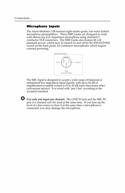
Microphone Inputs
The Alesis Multimix 12R features eight studio-grade, low-noise hybridmicrophone preamplifiers. These [MIC] jacks are designed to workwith almost any low-impedance microphone using standard 3-conductor XLR connectors. The [MIC] jacks also feature 48 voltphantom power, which may be turned on and off by the [PHANTOM]switch on the back panel, for condenser microphones which requireexternal powering.
Balanced Mic Input
GroundHot12
3
Cold
Socket (female)
The MIC Input is designed to accept a wide range of balanced orunbalanced low impedance input signals, with up to 60 dB ofamplification available (which is 10 to 20 dB more than many otherrack-mount mixers). It is wired with "pin 2 hot" according to theaccepted standard.
Use only one input per channel. The LINE IN jack and the MIC INjack of a channel can’t be used at the same time. If you turn up thelevel of a line source to hear it at the same time a microphone isconnected, you may damage the microphone.
Connections
Multimix 12R Reference Manual 7
CONNECTIONSInputs
Cable common sense
Make all connections to the Multimix 12R with the power turned offwherever possible. If you must connect or disconnect inputs whilepower is on, make sure the channel fader and [TRIM] are turned all theway down to avoid sudden pops and clicks which may damagespeakers or other equipment.
Use good-quality cable: 99% of all mixer problems turn out to becable or connector problems. Use the best quality cable you can, forhighest reliability and lowest noise. If something goes wrong, checkthe cable and its connection to the mixer first. If the connectors aredirty or corroded, clean them with isopropyl alcohol or otherapproved electrical contact cleaner before inserting them into theMultimix 12R. High quality cables are low-capacitance shielded cableswith a stranded (not solid) internal conductor and a low-resistanceshield. Although quality cables cost more, they do make a difference.
Route cables in your system correctly by observing the followingprecautions:
• Do not bundle audio cables with AC power cords.
• Avoid running audio cables, or placing the Multimix 12R itself,near sources of electromagnetic interference such as transformers,monitors, computers, etc.
• Never unplug a cable by pulling on the wire itself. Always unplugby firmly grasping the body of the plug and pulling directlyoutward.
• Do not place cables where they can be stepped on. Stepping on acable may not cause immediate damage, but it can compress theinsulation between the center conductor and shield (degradingperformance), or reduce the cable’s reliability.
• Avoid twisting the cable or having it make sharp, right angle turns.
Connections
Microphone Inputs
The Alesis Multimix 12R features eight studio-grade, low-noise hybridmicrophone preamplifiers. These [MIC] jacks are designed to workwith almost any low-impedance microphone using standard 3-conductor XLR connectors. The [MIC] jacks also feature 48 voltphantom power, which may be turned on and off by the [PHANTOM]switch on the back panel, for condenser microphones which requireexternal powering.
Balanced Mic Input
GroundHot12
3
Cold
Socket (female)
The MIC Input is designed to accept a wide range of balanced orunbalanced low impedance input signals, with up to 60 dB ofamplification available (which is 10 to 20 dB more than many otherrack-mount mixers). It is wired with "pin 2 hot" according to theaccepted standard.
Use only one input per channel. The LINE IN jack and the MIC INjack of a channel can’t be used at the same time. If you turn up thelevel of a line source to hear it at the same time a microphone isconnected, you may damage the microphone.
Connections
Multimix 12R Reference Manual 9
Phantom power
Certain types of microphones (called condenser microphones) requirea DC power supply from the mixer. “Phantom power” sends 48 voltsof DC through the microphone cable. If any of your microphonesneed phantom power, turn on the [PHANTOM POWER] switch on theMultimix 12R’s back panel to connect all the XLR MIC IN jacks to theMultimix 12R’s internal 48 volt phantom power source. Since thepower is applied equally to pins 2 and 3, phantom power should notaffect dynamic microphones (which do not require phantom power).However, make sure that your microphone cables have no shortcircuits or intermittent connections to avoid damage to the system.
Avoid connecting or disconnecting any microphones while[PHANTOM POWER] is turned on. Make all connections with theMultimix 12R powered off. If this is not possible, make sure thechannel's fader and [TRIM] are down, make the connections, then turnon the [PHANTOM POWER] switch on the back panel before bringingthe fader and [TRIM] back up. Many microphones make a loud "pop"when first powered, so make sure your faders are down to avoiddamaging your speakers or hearing.
Never connect the MIC jack to an UNBALANCED source or to a line-level device (such as a tape recorder or synthesizer) when phantompower is being used.
If none of your microphones need phantom power, leave thephantom power switch off.
Connections
Line-level devices (synthesizers, CD players,video)
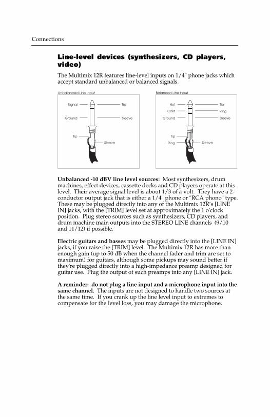
The Multimix 12R features line-level inputs on 1/4" phone jacks whichaccept standard unbalanced or balanced signals.
Tip
Sleeve
Signal
Ground
Tip
Sleeve
Unbalanced Line Input
Tip
Sleeve
Hot
Ground
Tip
Sleeve
Balanced Line Input
Ring
Ring
Cold
Unbalanced -10 dBV line level sources: Most synthesizers, drummachines, effect devices, cassette decks and CD players operate at thislevel. Their average signal level is about 1/3 of a volt. They have a 2-conductor output jack that is either a 1/4" phone or "RCA phono" type.These may be plugged directly into any of the Multimix 12R’s [LINEIN] jacks, with the [TRIM] level set at approximately the 1 o'clockposition. Plug stereo sources such as synthesizers, CD players, anddrum machine main outputs into the STEREO LINE channels (9/10and 11/12) if possible.
Electric guitars and basses may be plugged directly into the [LINE IN]jacks, if you raise the [TRIM] level. The Multimix 12R has more thanenough gain (up to 50 dB when the channel fader and trim are set tomaximum) for guitars, although some pickups may sound better ifthey're plugged directly into a high-impedance preamp designed forguitar use. Plug the output of such preamps into any [LINE IN] jack.
A reminder: do not plug a line input and a microphone input into thesame channel. The inputs are not designed to handle two sources atthe same time. If you crank up the line level input to extremes tocompensate for the level loss, you may damage the microphone.
Connections
Multimix 12R Reference Manual 9
Phantom power
Certain types of microphones (called condenser microphones) requirea DC power supply from the mixer. “Phantom power” sends 48 voltsof DC through the microphone cable. If any of your microphonesneed phantom power, turn on the [PHANTOM POWER] switch on theMultimix 12R’s back panel to connect all the XLR MIC IN jacks to theMultimix 12R’s internal 48 volt phantom power source. Since thepower is applied equally to pins 2 and 3, phantom power should notaffect dynamic microphones (which do not require phantom power).However, make sure that your microphone cables have no shortcircuits or intermittent connections to avoid damage to the system.
Avoid connecting or disconnecting any microphones while[PHANTOM POWER] is turned on. Make all connections with theMultimix 12R powered off. If this is not possible, make sure thechannel's fader and [TRIM] are down, make the connections, then turnon the [PHANTOM POWER] switch on the back panel before bringingthe fader and [TRIM] back up. Many microphones make a loud "pop"when first powered, so make sure your faders are down to avoiddamaging your speakers or hearing.
Never connect the MIC jack to an UNBALANCED source or to a line-level device (such as a tape recorder or synthesizer) when phantompower is being used.
If none of your microphones need phantom power, leave thephantom power switch off.
Connections
Line-level devices (synthesizers, CD players,video)
The Multimix 12R features line-level inputs on 1/4" phone jacks whichaccept standard unbalanced or balanced signals.
Tip
Sleeve
Signal
Ground
Tip
Sleeve
Unbalanced Line Input
Tip
Sleeve
Hot
Ground
Tip
Sleeve
Balanced Line Input
Ring
Ring
Cold
Unbalanced -10 dBV line level sources: Most synthesizers, drummachines, effect devices, cassette decks and CD players operate at thislevel. Their average signal level is about 1/3 of a volt. They have a 2-conductor output jack that is either a 1/4" phone or "RCA phono" type.These may be plugged directly into any of the Multimix 12R’s [LINEIN] jacks, with the [TRIM] level set at approximately the 1 o'clockposition. Plug stereo sources such as synthesizers, CD players, anddrum machine main outputs into the STEREO LINE channels (9/10and 11/12) if possible.
Electric guitars and basses may be plugged directly into the [LINE IN]jacks, if you raise the [TRIM] level. The Multimix 12R has more thanenough gain (up to 50 dB when the channel fader and trim are set tomaximum) for guitars, although some pickups may sound better ifthey're plugged directly into a high-impedance preamp designed forguitar use. Plug the output of such preamps into any [LINE IN] jack.
A reminder: do not plug a line input and a microphone input into thesame channel. The inputs are not designed to handle two sources atthe same time. If you crank up the line level input to extremes tocompensate for the level loss, you may damage the microphone.

Connections
Multimix 12R Reference Manual 11
Balanced +4 dBu line level sources: Professional recording andprocessing equipment typically provides a balanced, 3-conductorsignal output that is a higher voltage (1.24 volts nominal level) thanmost synthesizers and stereo equipment. The Multimix 12R’s [LINEIN] jacks are designed to handle these balanced inputs.
Balanced sources often feature XLR outputs. However, they shouldNOT be connected to the XLR [MIC] inputs of the Multimix 12R unlessabsolutely necessary, because the higher gain of the MIC jacks givesyou less headroom than the LINE IN jacks do (also, the source couldbe damaged by phantom power if it's turned on). Connect them tothe [LINE IN] jacks using an XLR-to-1/4 inch phone TRS (tip-ring-sleeve) cable, as shown below:
If the proper connector cable or adapter is not available, +4 dBu linelevel sources may be connected to the [MIC] jacks ONLY IFPHANTOM POWER WILL NOT BE USED!!
Connecting a line-level output to a phantom-powered XLR input on theAlesis Multimix 12R may cause damage to the external unit. Alesis cannotbe responsible for any damages caused by this kind of misuse.
The nominal trim setting for a +4 dBu signal plugged into a line input isapproximately 11 o'clock (12 o'clock on the stereo channels). This willgive you plenty of headroom to start with.
Maximum levels: The maximum level the [MIC] jack can receive withthe [TRIM] control full counter-clockwise is +12 dBu before clipping, sothere’s only 8 dB of headroom if you plug a +4 dBu line source into themic jack. The [LINE IN] jack on channels 1-8 may receive levels up to+32 dBu without clipping, a headroom advantage of 20 dB. The stereochannels may receive a +22 dBu (balanced or unbalanced) maximuminput.
Connections
TAPE IN jacks
The [TAPE IN] jacks on the rear panel are designed for playback of astereo tape deck (or any other -10 dBV level signal) through the[MONITOR OUT] and [PHONES] jacks only. A signal at the [TAPE IN]jacks cannot be heard from the [MAIN OUT] jacks.
This allows you to use the Multimix 12R to monitor a mixdown to a 2-track deck through your headphones. (If you plugged your mixdowndeck into the line inputs on the channels, it would cause feedbackwhen you press “record”.) By placing the [PHONES/MONITOR]switch in the TAPE position, you will hear the mixer's output after ithas been passed through the mixdown deck, so you can make surethat it is recording correctly.
• Another use for the [TAPE IN] jacks is to play a CD or tape into a PAsystem, automatically turning off all the microphones into the main PAsystem when the front panel MSTR/TAPE switch is set to the TAPEposition. Note that in this application, the PA system must be fed from theMONITOR OUT instead of the MAIN OUT jacks, and will be affected bythe level of the [PHONES/MONITOR] control as well as by the[MASTER] control fader.
Connections
Multimix 12R Reference Manual 11
Balanced +4 dBu line level sources: Professional recording andprocessing equipment typically provides a balanced, 3-conductorsignal output that is a higher voltage (1.24 volts nominal level) thanmost synthesizers and stereo equipment. The Multimix 12R’s [LINEIN] jacks are designed to handle these balanced inputs.
Balanced sources often feature XLR outputs. However, they shouldNOT be connected to the XLR [MIC] inputs of the Multimix 12R unlessabsolutely necessary, because the higher gain of the MIC jacks givesyou less headroom than the LINE IN jacks do (also, the source couldbe damaged by phantom power if it's turned on). Connect them tothe [LINE IN] jacks using an XLR-to-1/4 inch phone TRS (tip-ring-sleeve) cable, as shown below:
If the proper connector cable or adapter is not available, +4 dBu linelevel sources may be connected to the [MIC] jacks ONLY IFPHANTOM POWER WILL NOT BE USED!!
Connecting a line-level output to a phantom-powered XLR input on theAlesis Multimix 12R may cause damage to the external unit. Alesis cannotbe responsible for any damages caused by this kind of misuse.
The nominal trim setting for a +4 dBu signal plugged into a line input isapproximately 11 o'clock (12 o'clock on the stereo channels). This willgive you plenty of headroom to start with.
Maximum levels: The maximum level the [MIC] jack can receive withthe [TRIM] control full counter-clockwise is +12 dBu before clipping, sothere’s only 8 dB of headroom if you plug a +4 dBu line source into themic jack. The [LINE IN] jack on channels 1-8 may receive levels up to+32 dBu without clipping, a headroom advantage of 20 dB. The stereochannels may receive a +22 dBu (balanced or unbalanced) maximuminput.
Connections
TAPE IN jacks
The [TAPE IN] jacks on the rear panel are designed for playback of astereo tape deck (or any other -10 dBV level signal) through the[MONITOR OUT] and [PHONES] jacks only. A signal at the [TAPE IN]jacks cannot be heard from the [MAIN OUT] jacks.
This allows you to use the Multimix 12R to monitor a mixdown to a 2-track deck through your headphones. (If you plugged your mixdowndeck into the line inputs on the channels, it would cause feedbackwhen you press “record”.) By placing the [PHONES/MONITOR]switch in the TAPE position, you will hear the mixer's output after ithas been passed through the mixdown deck, so you can make surethat it is recording correctly.
• Another use for the [TAPE IN] jacks is to play a CD or tape into a PAsystem, automatically turning off all the microphones into the main PAsystem when the front panel MSTR/TAPE switch is set to the TAPEposition. Note that in this application, the PA system must be fed from theMONITOR OUT instead of the MAIN OUT jacks, and will be affected bythe level of the [PHONES/MONITOR] control as well as by the[MASTER] control fader.

Connections
Multimix 12R Reference Manual 13
Phonograph turntables
If you're using a record turntable, you may not plug it directly into theline inputs of the Multimix 12R (well, you can, but it will sound verythin and noisy). Obtain a phono preamp from your dealer or anelectronics specialty store.
1. Plug the outputs of the phonograph pickup into the RIAA-equalized phono preamp.
2. Plug the outputs of the preamp into the LINE IN 9-10 or 11-12inputs of the Multimix 12R.
Do not connect any of the following to anyinput of the Multimix 12R!
• The speaker output of any power amplifier.
• Any source that is too loud for the input (no more than 3 volts RMSinto a [MIC] jack or 13 volts RMS into a [LINE IN] jack).
• Any unshielded cable.
Connections
How to connect effect devices and signalprocessors
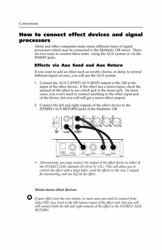
Alesis and other companies make many different types of signalprocessors which may be connected to the Multimix 12R mixer. Thereare two ways to connect these units: using the AUX system or via theINSERT jacks.
Effects via Aux Send and Aux Return
If you want to add an effect such as reverb, chorus, or delay to severaldifferent inputs at once, you will use the AUX system.
1. Connect the AUX 2 (POST) AUX SEND output of the 12R to theinput of the effect device. If the effect has a stereo input, check themanual of the effect to see which jack is the mono jack. (In mostcases, you won't need to connect anything to the other input jackof the device, but you will still get a stereo effect output).
2. Connect the left and right outputs of the effect device to the[STEREO AUX RETURN] jacks of the Multimix 12R.
• Alternatively, you may connect the output of the effect device to either ofthe STEREO LINE channels ([9-10 or 11-12].) This will allow you tocontrol the effect with a large fader, send the effects to the Aux 1 outputfor monitoring, and use EQ on the effect.
About stereo effect devices
If your effect unit has two inputs, in most cases you need to connect fromonly ONE Aux Send to the left (mono) input of the effect unit, but you willstill connect both the left and right outputs of the effect to the STEREO AUXRETURN.
Connections
Multimix 12R Reference Manual 13
Phonograph turntables
If you're using a record turntable, you may not plug it directly into theline inputs of the Multimix 12R (well, you can, but it will sound verythin and noisy). Obtain a phono preamp from your dealer or anelectronics specialty store.
1. Plug the outputs of the phonograph pickup into the RIAA-equalized phono preamp.
2. Plug the outputs of the preamp into the LINE IN 9-10 or 11-12inputs of the Multimix 12R.
Do not connect any of the following to anyinput of the Multimix 12R!
• The speaker output of any power amplifier.
• Any source that is too loud for the input (no more than 3 volts RMSinto a [MIC] jack or 13 volts RMS into a [LINE IN] jack).
• Any unshielded cable.
Connections
How to connect effect devices and signalprocessors
Alesis and other companies make many different types of signalprocessors which may be connected to the Multimix 12R mixer. Thereare two ways to connect these units: using the AUX system or via theINSERT jacks.
Effects via Aux Send and Aux Return
If you want to add an effect such as reverb, chorus, or delay to severaldifferent inputs at once, you will use the AUX system.
1. Connect the AUX 2 (POST) AUX SEND output of the 12R to theinput of the effect device. If the effect has a stereo input, check themanual of the effect to see which jack is the mono jack. (In mostcases, you won't need to connect anything to the other input jackof the device, but you will still get a stereo effect output).
2. Connect the left and right outputs of the effect device to the[STEREO AUX RETURN] jacks of the Multimix 12R.
• Alternatively, you may connect the output of the effect device to either ofthe STEREO LINE channels ([9-10 or 11-12].) This will allow you tocontrol the effect with a large fader, send the effects to the Aux 1 outputfor monitoring, and use EQ on the effect.
About stereo effect devices
If your effect unit has two inputs, in most cases you need to connect fromonly ONE Aux Send to the left (mono) input of the effect unit, but you willstill connect both the left and right outputs of the effect to the STEREO AUXRETURN.
Connections
Multimix 12R Reference Manual 15
You don’t need to connect anything to the other input of the effect,because most effect units use the stereo inputs only to provide a pathfor the “dry” stereo signal when the effect is connected directlybetween an instrument and an amplifier. In mixing applications suchas with the Multimix 12R, you will set the effect’s wet/dry balance allthe way to “wet” (effects only, no direct signal). The effect device willgenerate an artificial stereo output from the signal input. Check themanual for your effect device for more information.
On the other hand, true dual-channel effects processors (such as theAlesis QuadraVerb 2) may be connected to two different sends to takeadvantage of the dual processing capability. Dual-channel processorsallow the left and right inputs to be used for different kinds of effects(for example, the left input to a stereo chorus while the right input isused for a stereo reverb).
Using Aux 1 as an effects send
Note that [AUX 1] may also be used as an extra effects send. AlthoughAux 1 is a pre-fader send, and normally used for stage monitoring or aseparate headphone mix while recording, it may also be used as aneffects send so you can add different effects to different channels. Justremember that the “PRE” under [AUX 1] means that when you movea fader up or down you won’t change the level going to an effect fromAux 1. If you change fader levels, you will need to adjust Aux 1 levelsto maintain the same balance between dry and effected signal.
In-line processing using the INSERT jacks(compressors & equalizers)
Some signal processors are designed to be used on one signal at atime, with the entire signal being processed instead of a mix of effectedand uneffected signal. The purpose of the INSERT jacks on channels 1-8 is to allow you to insert a compressor, equalizer, or other effect intothe signal path of a single channel after its preamplifier and [TRIM]control, but before the Multimix 12R's own EQ, aux sends, and fader.The INSERT jacks may also be used as direct outputs to a recorder.
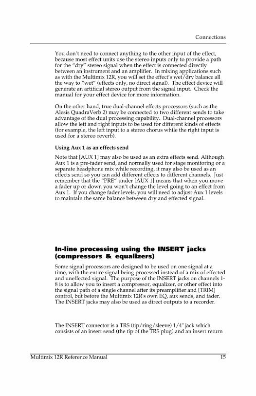
The INSERT connector is a TRS (tip/ring/sleeve) 1/4" jack whichconsists of an insert send (the tip of the TRS plug) and an insert return
Connections
(the ring of a TRS plug). A special Y-cable consisting of a TRS 1/4" plugon one end and two mono 1/4" plugs on the other end is required.
Tip
Ring
Sleeve
Send
Return
Ground
Tip
Ring Sleeve
Insert Points
Note that you will not hear any signal through the Multimix 12R ifthe INSERT jack is plugged in and the signal is interrupted in thatloop (by the other cables being disconnected, the processor beingturned off, or the volume turned off in the processor).
Connecting an in-line processor
1. Obtain a "stereo splitter" insert cable from your dealer.
2. Connect the stereo (TRS) end to the INSERT jack of the Multimix12R.
3. Connect the mono plug from the tip connector to the input of theprocessor.
4. Connect the mono plug from the ring connector to the output ofthe processor.
If you're not sure which mono plug is from the tip and which is fromthe ring, check to see if the cable is labeled. If not, simply try it oneway and if the signal doesn't pass through, swap the input and outputplugs the other way.
• The [INSERT] jack may also be used as a direct output to a multitrackrecorder such as the ADAT. The send from the insert jack is where thecleanest mic preamp signal may be obtained, without passing through the EQor channel circuitry. Simply insert the plug to the first "click" (the ringconnector) and it will not interrupt the flow through the mixer, while
Connections
Multimix 12R Reference Manual 15
You don’t need to connect anything to the other input of the effect,because most effect units use the stereo inputs only to provide a pathfor the “dry” stereo signal when the effect is connected directlybetween an instrument and an amplifier. In mixing applications suchas with the Multimix 12R, you will set the effect’s wet/dry balance allthe way to “wet” (effects only, no direct signal). The effect device willgenerate an artificial stereo output from the signal input. Check themanual for your effect device for more information.
On the other hand, true dual-channel effects processors (such as theAlesis QuadraVerb 2) may be connected to two different sends to takeadvantage of the dual processing capability. Dual-channel processorsallow the left and right inputs to be used for different kinds of effects(for example, the left input to a stereo chorus while the right input isused for a stereo reverb).
Using Aux 1 as an effects send
Note that [AUX 1] may also be used as an extra effects send. AlthoughAux 1 is a pre-fader send, and normally used for stage monitoring or aseparate headphone mix while recording, it may also be used as aneffects send so you can add different effects to different channels. Justremember that the “PRE” under [AUX 1] means that when you movea fader up or down you won’t change the level going to an effect fromAux 1. If you change fader levels, you will need to adjust Aux 1 levelsto maintain the same balance between dry and effected signal.
In-line processing using the INSERT jacks(compressors & equalizers)
Some signal processors are designed to be used on one signal at atime, with the entire signal being processed instead of a mix of effectedand uneffected signal. The purpose of the INSERT jacks on channels 1-8 is to allow you to insert a compressor, equalizer, or other effect intothe signal path of a single channel after its preamplifier and [TRIM]control, but before the Multimix 12R's own EQ, aux sends, and fader.The INSERT jacks may also be used as direct outputs to a recorder.
The INSERT connector is a TRS (tip/ring/sleeve) 1/4" jack whichconsists of an insert send (the tip of the TRS plug) and an insert return
Connections
(the ring of a TRS plug). A special Y-cable consisting of a TRS 1/4" plugon one end and two mono 1/4" plugs on the other end is required.
Tip
Ring
Sleeve
Send
Return
Ground
Tip
Ring Sleeve
Insert Points
Note that you will not hear any signal through the Multimix 12R ifthe INSERT jack is plugged in and the signal is interrupted in thatloop (by the other cables being disconnected, the processor beingturned off, or the volume turned off in the processor).
Connecting an in-line processor
1. Obtain a "stereo splitter" insert cable from your dealer.
2. Connect the stereo (TRS) end to the INSERT jack of the Multimix12R.
3. Connect the mono plug from the tip connector to the input of theprocessor.
4. Connect the mono plug from the ring connector to the output ofthe processor.
If you're not sure which mono plug is from the tip and which is fromthe ring, check to see if the cable is labeled. If not, simply try it oneway and if the signal doesn't pass through, swap the input and outputplugs the other way.
• The [INSERT] jack may also be used as a direct output to a multitrackrecorder such as the ADAT. The send from the insert jack is where thecleanest mic preamp signal may be obtained, without passing through the EQor channel circuitry. Simply insert the plug to the first "click" (the ringconnector) and it will not interrupt the flow through the mixer, while

Connections
Multimix 12R Reference Manual 17
providing a direct output. Or, put the recorder into INPUT mode and insertthe plug all the way, connecting the input and output of each track of therecorder into each channel path of the mixer. This will allow playbackmonitoring of the recorder. See the Applications chapter for moreinformation.
For more information on using the AUX and INSERT systems, see the“Operating Instructions” chapter of this manual.
Connections
Outputs
To a stereo PA system or instrumentamplifier
Balanced
Check to see if your amplifier can accept balanced inputs. If so,connect the [MAIN OUT BALANCED] jacks of the Multimix 12R to theinput of the amp using a 3-conductor cable, with a 1/4" TRS plug onone end, and the connector used by the amp (usually a 1/4" TRSconnector; sometimes an XLR or terminal strip) on the other.
• You may also connect the [MONITOR OUT] jacks of the mixer to youramplifier. This will allow you to switch between hearing 2-track playbackand the stereo output of the mixer, using the front panel monitor switch.
Unbalanced
If the amp is unbalanced, use a standard shielded "patch cord" with1/4" connectors.
To a mono system
If your PA system or amplifier isn't stereo, connect either the left orright MAIN OUT jacks to the input of the system. Make sure that all[PAN] controls are in the center or turned to the side you're using.
To a stage monitor (foldback) system
If your PA system has a separate amplifier and speaker system formonitors, connect a cable from the [AUX 1 PRE AUX SENDS] jack tothe amp input, in the same manner as above. The Aux 1 system is apre-fader, post-EQ send with a balanced/unbalanced output. In moststage monitor situations, we recommend connecting a third-octavegraphic equalizer such as the Alesis MEQ-230 between the mixer andthe amp to control feedback.
The Aux 1 output may be connected in the same way for a number ofdifferent applications such as:
• Headphone cue feed for multitrack recording• Separate broadcast mix from a PA system• Zone feed for a separate region of a PA system

Connections
Multimix 12R Reference Manual 17
providing a direct output. Or, put the recorder into INPUT mode and insertthe plug all the way, connecting the input and output of each track of therecorder into each channel path of the mixer. This will allow playbackmonitoring of the recorder. See the Applications chapter for moreinformation.
For more information on using the AUX and INSERT systems, see the“Operating Instructions” chapter of this manual.
Connections
Outputs
To a stereo PA system or instrumentamplifier
Balanced
Check to see if your amplifier can accept balanced inputs. If so,connect the [MAIN OUT BALANCED] jacks of the Multimix 12R to theinput of the amp using a 3-conductor cable, with a 1/4" TRS plug onone end, and the connector used by the amp (usually a 1/4" TRSconnector; sometimes an XLR or terminal strip) on the other.
• You may also connect the [MONITOR OUT] jacks of the mixer to youramplifier. This will allow you to switch between hearing 2-track playbackand the stereo output of the mixer, using the front panel monitor switch.
Unbalanced
If the amp is unbalanced, use a standard shielded "patch cord" with1/4" connectors.
To a mono system
If your PA system or amplifier isn't stereo, connect either the left orright MAIN OUT jacks to the input of the system. Make sure that all[PAN] controls are in the center or turned to the side you're using.
To a stage monitor (foldback) system
If your PA system has a separate amplifier and speaker system formonitors, connect a cable from the [AUX 1 PRE AUX SENDS] jack tothe amp input, in the same manner as above. The Aux 1 system is apre-fader, post-EQ send with a balanced/unbalanced output. In moststage monitor situations, we recommend connecting a third-octavegraphic equalizer such as the Alesis MEQ-230 between the mixer andthe amp to control feedback.
The Aux 1 output may be connected in the same way for a number ofdifferent applications such as:
• Headphone cue feed for multitrack recording• Separate broadcast mix from a PA system• Zone feed for a separate region of a PA system
Connections
Multimix 12R Reference Manual 19
To another mixer
The main or monitor outputs of the Multimix 12R may be connected toa larger mixing console. Consult the manual for the other mixer formore information. If the mixer has "SUB IN" jacks, connect to those.Alternatively, you may simply connect the MAIN OUT or MONITOROUT jacks of the Multimix 12R to two line-level inputs on the othermixer. If you do, check to see what level those inputs are designed for.
• If the inputs of the other mixer can handle +4 dBu balanced or -2dBu unbalanced levels, simply connect the [MAIN OUTBALANCED] outputs to the other mixer's line inputs.
• If the inputs are designed for -10 dBV level inputs (such as mostkeyboard and guitar amplifiers, and consumer stereo amplifiers),connect the [MAIN OUT -10 dBV] outputs to the line inputs of theexternal mixer.
If the connection is made properly, the Multimix 12R will not distortthe input of the other mixer. You may need to adjust the input trim ofthe other mixer to get the best dynamic range.
To a stereo tape recorder
If you want to record the output of the mixer into a typical stereocassette or DAT deck, connect the [MAIN OUT -10 dBV] phono jacks tothe left and right inputs of the cassette deck using a standard stereophono-to-phono (RCA) cable.
If your recorder is a professional type with balanced +4 inputs, in mostcases you should connect the [MAIN OUT BALANCED] jacks of themixer to the inputs of the recorder.
• If you connect the [MONITOR OUT] jacks to the recorder, the levelwill be affected by the [PHONES/MONITOR] level control on the frontpanel. However, if you're using the [TAPE IN] jacks to monitorplayback, you run the risk of feedback if you press the MSTR/TAPEswitch while in record mode.
Connections
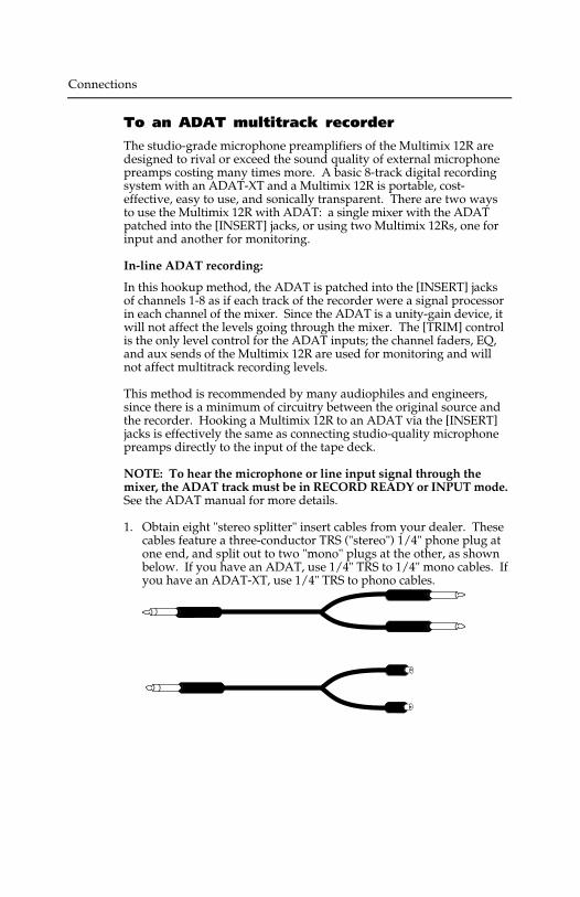
To an ADAT multitrack recorder
The studio-grade microphone preamplifiers of the Multimix 12R aredesigned to rival or exceed the sound quality of external microphonepreamps costing many times more. A basic 8-track digital recordingsystem with an ADAT-XT and a Multimix 12R is portable, cost-effective, easy to use, and sonically transparent. There are two waysto use the Multimix 12R with ADAT: a single mixer with the ADATpatched into the [INSERT] jacks, or using two Multimix 12Rs, one forinput and another for monitoring.
In-line ADAT recording:
In this hookup method, the ADAT is patched into the [INSERT] jacksof channels 1-8 as if each track of the recorder were a signal processorin each channel of the mixer. Since the ADAT is a unity-gain device, itwill not affect the levels going through the mixer. The [TRIM] controlis the only level control for the ADAT inputs; the channel faders, EQ,and aux sends of the Multimix 12R are used for monitoring and willnot affect multitrack recording levels.
This method is recommended by many audiophiles and engineers,since there is a minimum of circuitry between the original source andthe recorder. Hooking a Multimix 12R to an ADAT via the [INSERT]jacks is effectively the same as connecting studio-quality microphonepreamps directly to the input of the tape deck.
NOTE: To hear the microphone or line input signal through themixer, the ADAT track must be in RECORD READY or INPUT mode.See the ADAT manual for more details.
1. Obtain eight "stereo splitter" insert cables from your dealer. Thesecables feature a three-conductor TRS ("stereo") 1/4" phone plug atone end, and split out to two "mono" plugs at the other, as shownbelow. If you have an ADAT, use 1/4" TRS to 1/4" mono cables. Ifyou have an ADAT-XT, use 1/4" TRS to phono cables.
Connections
Multimix 12R Reference Manual 19
To another mixer
The main or monitor outputs of the Multimix 12R may be connected toa larger mixing console. Consult the manual for the other mixer formore information. If the mixer has "SUB IN" jacks, connect to those.Alternatively, you may simply connect the MAIN OUT or MONITOROUT jacks of the Multimix 12R to two line-level inputs on the othermixer. If you do, check to see what level those inputs are designed for.
• If the inputs of the other mixer can handle +4 dBu balanced or -2dBu unbalanced levels, simply connect the [MAIN OUTBALANCED] outputs to the other mixer's line inputs.
• If the inputs are designed for -10 dBV level inputs (such as mostkeyboard and guitar amplifiers, and consumer stereo amplifiers),connect the [MAIN OUT -10 dBV] outputs to the line inputs of theexternal mixer.
If the connection is made properly, the Multimix 12R will not distortthe input of the other mixer. You may need to adjust the input trim ofthe other mixer to get the best dynamic range.
To a stereo tape recorder
If you want to record the output of the mixer into a typical stereocassette or DAT deck, connect the [MAIN OUT -10 dBV] phono jacks tothe left and right inputs of the cassette deck using a standard stereophono-to-phono (RCA) cable.
If your recorder is a professional type with balanced +4 inputs, in mostcases you should connect the [MAIN OUT BALANCED] jacks of themixer to the inputs of the recorder.
• If you connect the [MONITOR OUT] jacks to the recorder, the levelwill be affected by the [PHONES/MONITOR] level control on the frontpanel. However, if you're using the [TAPE IN] jacks to monitorplayback, you run the risk of feedback if you press the MSTR/TAPEswitch while in record mode.
Connections
To an ADAT multitrack recorder
The studio-grade microphone preamplifiers of the Multimix 12R aredesigned to rival or exceed the sound quality of external microphonepreamps costing many times more. A basic 8-track digital recordingsystem with an ADAT-XT and a Multimix 12R is portable, cost-effective, easy to use, and sonically transparent. There are two waysto use the Multimix 12R with ADAT: a single mixer with the ADATpatched into the [INSERT] jacks, or using two Multimix 12Rs, one forinput and another for monitoring.
In-line ADAT recording:
In this hookup method, the ADAT is patched into the [INSERT] jacksof channels 1-8 as if each track of the recorder were a signal processorin each channel of the mixer. Since the ADAT is a unity-gain device, itwill not affect the levels going through the mixer. The [TRIM] controlis the only level control for the ADAT inputs; the channel faders, EQ,and aux sends of the Multimix 12R are used for monitoring and willnot affect multitrack recording levels.
This method is recommended by many audiophiles and engineers,since there is a minimum of circuitry between the original source andthe recorder. Hooking a Multimix 12R to an ADAT via the [INSERT]jacks is effectively the same as connecting studio-quality microphonepreamps directly to the input of the tape deck.
NOTE: To hear the microphone or line input signal through themixer, the ADAT track must be in RECORD READY or INPUT mode.See the ADAT manual for more details.
1. Obtain eight "stereo splitter" insert cables from your dealer. Thesecables feature a three-conductor TRS ("stereo") 1/4" phone plug atone end, and split out to two "mono" plugs at the other, as shownbelow. If you have an ADAT, use 1/4" TRS to 1/4" mono cables. Ifyou have an ADAT-XT, use 1/4" TRS to phono cables.

Connections
Multimix 12R Reference Manual 21
2. Connect the stereo/TRS end to the INSERT jack of channel 1 of theMultimix 12R.
3. Connect the mono plug from the tip connector to the input of theADAT. NOTE: the ADAT’s tracks are arranged from left to right on theback panel, and the mixer’s channels are from right to left, so the wireswill have to cross over.
4. Connect the mono plug from the ring connector to the output ofthe ADAT.
If you're not sure which mono plug is from the tip and which isfrom the ring, check to see if the cable box has that information. Ifnot, simply try it one way and play a prerecorded tape from theADAT. If you can't hear output from the mixer with the faders andmaster up, swap the input and output plugs the other way.
5. Plug in channels 2-8 of the mixer to tracks 2-8 of the ADAT in thesame way.
1 2 3 4 5 6 7 8
OUTPUT
INPUT
OUTPUT
INPUT
LOCATE/PLAYLRC REMOTE
PUNCHIN/OUT DIGITAL SYNC
OUTIN OUTIN
Using two Multimix 12Rs for more flexibility:
The in-line method may be used for recording one source to a track.But if you want to record a mix of microphones or other sources ontoa pair of tracks, two Multimix 12Rs can do the job more quietly and ina smaller space than expensive dedicated recording consoles. One 12Ris the "source" mixer which feeds the ADAT's inputs, and the other isthe "monitor/mixdown" mixer which receives the ADAT's outputs.
1. Plug the -10 dBV MAIN OUT jacks of the "source" 12R to trackinputs 1 and 2 of the ADAT.
Connections
• Because the ADAT has normalled inputs, the stereo output of the sourcemixer may be recorded on other tracks without repatching. The leftoutput of the mixer will appear at the inputs of tracks 1, 3, 5 & 7; the rightoutput will appear at track 2, 4, 6 & 8. On the ADAT-XT, press and hold[ANALOG INPUT] and the REC READY keys for track 1 or 2 to activatethis "built-in patch bay" feature.
2. Plug track outputs 1-8 of the ADAT to LINE IN 1-8 of the"monitor/mixdown" 12R. Note that output 1 is on the left of theADAT, but on the right of the mixer, so the wires must cross over.
3. To record more than two tracks at a time, plug a mono cable fromthe INSERT jack of any channels of the mixer to the input of anytrack. By plugging the cable all the way in the INSERT jack, andnot returning the signal from the recorder, the individual channelswill be removed from the stereo mix. This way, you can record astereo mix of several inputs on any two tracks whilesimultaneously recording individual sources on other tracks.

Connections
Multimix 12R Reference Manual 21
2. Connect the stereo/TRS end to the INSERT jack of channel 1 of theMultimix 12R.
3. Connect the mono plug from the tip connector to the input of theADAT. NOTE: the ADAT’s tracks are arranged from left to right on theback panel, and the mixer’s channels are from right to left, so the wireswill have to cross over.
4. Connect the mono plug from the ring connector to the output ofthe ADAT.
If you're not sure which mono plug is from the tip and which isfrom the ring, check to see if the cable box has that information. Ifnot, simply try it one way and play a prerecorded tape from theADAT. If you can't hear output from the mixer with the faders andmaster up, swap the input and output plugs the other way.
5. Plug in channels 2-8 of the mixer to tracks 2-8 of the ADAT in thesame way.
1 2 3 4 5 6 7 8
OUTPUT
INPUT
OUTPUT
INPUT
LOCATE/PLAYLRC REMOTE
PUNCHIN/OUT DIGITAL SYNC
OUTIN OUTIN
Using two Multimix 12Rs for more flexibility:
The in-line method may be used for recording one source to a track.But if you want to record a mix of microphones or other sources ontoa pair of tracks, two Multimix 12Rs can do the job more quietly and ina smaller space than expensive dedicated recording consoles. One 12Ris the "source" mixer which feeds the ADAT's inputs, and the other isthe "monitor/mixdown" mixer which receives the ADAT's outputs.
1. Plug the -10 dBV MAIN OUT jacks of the "source" 12R to trackinputs 1 and 2 of the ADAT.
Connections
• Because the ADAT has normalled inputs, the stereo output of the sourcemixer may be recorded on other tracks without repatching. The leftoutput of the mixer will appear at the inputs of tracks 1, 3, 5 & 7; the rightoutput will appear at track 2, 4, 6 & 8. On the ADAT-XT, press and hold[ANALOG INPUT] and the REC READY keys for track 1 or 2 to activatethis "built-in patch bay" feature.
2. Plug track outputs 1-8 of the ADAT to LINE IN 1-8 of the"monitor/mixdown" 12R. Note that output 1 is on the left of theADAT, but on the right of the mixer, so the wires must cross over.
3. To record more than two tracks at a time, plug a mono cable fromthe INSERT jack of any channels of the mixer to the input of anytrack. By plugging the cable all the way in the INSERT jack, andnot returning the signal from the recorder, the individual channelswill be removed from the stereo mix. This way, you can record astereo mix of several inputs on any two tracks whilesimultaneously recording individual sources on other tracks.
Connections
Multimix 12R Reference Manual 23
Phones
The [PHONES] jack on the front panel is designed for most stereoheadphones. The internal headphone amplifier outputs the maximumpower allowed by safety standards. The impedance and efficiency ofthe headphones will determine the maximum volume available. Eight-ohm headphones may be louder at a given setting than 150-ohm or600-ohm headphones; however, there should be enough gain to driveany dynamic headphone to reasonable levels, if the mixer is being runproperly.
Note that the PHONES/MONITOR level control on the front panelaffects both the headphone jack on the front panel and the [MONITOROUT] balanced jacks on the back panel.
Monitor Out
The [MONITOR OUT] jacks give you a signal that will be the same asthe MAIN OUT, as long as the front panel [MSTR/TAPE] switch is inthe "MSTR" position. The only difference is that the MONITOR OUTsignal is after the front panel PHONES level control. When thatcontrol is up full, the MONITOR OUT jack will be 10 dB louder than theMAIN OUT. The PHONES control may be lowered to the point wherethe MONITOR OUT is almost at microphone level, low enough to bepatched into the microphone-level inputs of a camcorder or house PAsystem. However, connect the monitor output to line level inputswherever possible.
Connections

Connections
Multimix 12R Reference Manual 23
Phones
The [PHONES] jack on the front panel is designed for most stereoheadphones. The internal headphone amplifier outputs the maximumpower allowed by safety standards. The impedance and efficiency ofthe headphones will determine the maximum volume available. Eight-ohm headphones may be louder at a given setting than 150-ohm or600-ohm headphones; however, there should be enough gain to driveany dynamic headphone to reasonable levels, if the mixer is being runproperly.
Note that the PHONES/MONITOR level control on the front panelaffects both the headphone jack on the front panel and the [MONITOROUT] balanced jacks on the back panel.
Monitor Out
The [MONITOR OUT] jacks give you a signal that will be the same asthe MAIN OUT, as long as the front panel [MSTR/TAPE] switch is inthe "MSTR" position. The only difference is that the MONITOR OUTsignal is after the front panel PHONES level control. When thatcontrol is up full, the MONITOR OUT jack will be 10 dB louder than theMAIN OUT. The PHONES control may be lowered to the point wherethe MONITOR OUT is almost at microphone level, low enough to bepatched into the microphone-level inputs of a camcorder or house PAsystem. However, connect the monitor output to line level inputswherever possible.
Connections

Operating Instructions
Multimix 12R Reference Manual 25
OPERATINGINSTRUCTIONS
Before turning the mixer on, "zero out'the controls
To avoid surprises while you're setting up a new system, set allcontrols to their "zeroed out" positions as follows before proceeding:
1. Make all connections to the Multimix 12R, as described in theprevious chapter.
2. Bring all channel faders and the [MASTER] fader down tominimum.
3. Set all [TRIM] controls to minimum (full counterclockwise).
4. Set all [AUX 1], [AUX 2], STEREO AUX RETURN,[PHONES/MONITOR] controls to minimum (fullcounterclockwise).
5. Set all [HIGH] and [LOW] EQ, [PAN], and [BAL] controls to "12o'clock".
Operating Instructions
Setting input trim levels
Proper setting of the [TRIM] controls is crucial to low-noise, distortion-free operation. If the trim is set too high, there will be distortion evenif the channel faders are low. If the trim is set too low and the channelfaders are raised to get the signal loud enough, you will be amplifyingthe noise of the mixer.
Instead of doing this, get as much gain as possible as close to the signalsource as possible. If you've plugged a synthesizer or other line-levelsource into the Multimix 12R, set its output volume to maximum. If amicrophone is the source, the Multimix 12R's [TRIM] control willdetermine the gain of the system.
The goal is to get the signal as loud as possible as early as possiblein the signal path, without causing clipping (distortion) anywhere inthe path or in the sound system.
PEAK LED method
Each channel of the Multimix 12R has its own [PEAK] indicator, whichwill light when the signal level rises to within 6 dB of clipping. Insituations where the maximum signal-to-noise ratio is required (suchas digital recording), use the PEAK LED as a guide for setting the[TRIM] control.
When the PEAK LED is flashing, it does NOT necessarily mean thatdistortion has occurred. There is usually some headroom left if the PEAKLED is flashing momentarily on the loudest peaks.
1. With the sound source active, and the channel fader down tominimum, raise the [TRIM] control until the PEAK LED flashesoccasionally on the loudest transients.
2. If desired, lower the [TRIM] control slightly until the flashing stops.
Note for extremely high level line inputs in stereo channels: If the[TRIM] setting is set below unity (12 o'clock position) on a stereochannel, it is possible for the first input stage to clip without thePEAK LED coming on. If distortion is still heard after lowering thetrim to its minimum setting, it means the source is extremely high(+22 dBu or higher). In this case you must lower the output level ofthe source, use an external pad, or repatch to a LINE IN onchannels 1-8 (which can take up to +32 dBu levels before clipping).
Operating Instructions
Multimix 12R Reference Manual 25
OPERATINGINSTRUCTIONS
Before turning the mixer on, "zero out'the controls
To avoid surprises while you're setting up a new system, set allcontrols to their "zeroed out" positions as follows before proceeding:
1. Make all connections to the Multimix 12R, as described in theprevious chapter.
2. Bring all channel faders and the [MASTER] fader down tominimum.
3. Set all [TRIM] controls to minimum (full counterclockwise).
4. Set all [AUX 1], [AUX 2], STEREO AUX RETURN,[PHONES/MONITOR] controls to minimum (fullcounterclockwise).
5. Set all [HIGH] and [LOW] EQ, [PAN], and [BAL] controls to "12o'clock".
Operating Instructions
Setting input trim levels
Proper setting of the [TRIM] controls is crucial to low-noise, distortion-free operation. If the trim is set too high, there will be distortion evenif the channel faders are low. If the trim is set too low and the channelfaders are raised to get the signal loud enough, you will be amplifyingthe noise of the mixer.
Instead of doing this, get as much gain as possible as close to the signalsource as possible. If you've plugged a synthesizer or other line-levelsource into the Multimix 12R, set its output volume to maximum. If amicrophone is the source, the Multimix 12R's [TRIM] control willdetermine the gain of the system.
The goal is to get the signal as loud as possible as early as possiblein the signal path, without causing clipping (distortion) anywhere inthe path or in the sound system.
PEAK LED method
Each channel of the Multimix 12R has its own [PEAK] indicator, whichwill light when the signal level rises to within 6 dB of clipping. Insituations where the maximum signal-to-noise ratio is required (suchas digital recording), use the PEAK LED as a guide for setting the[TRIM] control.
When the PEAK LED is flashing, it does NOT necessarily mean thatdistortion has occurred. There is usually some headroom left if the PEAKLED is flashing momentarily on the loudest peaks.
1. With the sound source active, and the channel fader down tominimum, raise the [TRIM] control until the PEAK LED flashesoccasionally on the loudest transients.
2. If desired, lower the [TRIM] control slightly until the flashing stops.
Note for extremely high level line inputs in stereo channels: If the[TRIM] setting is set below unity (12 o'clock position) on a stereochannel, it is possible for the first input stage to clip without thePEAK LED coming on. If distortion is still heard after lowering thetrim to its minimum setting, it means the source is extremely high(+22 dBu or higher). In this case you must lower the output level ofthe source, use an external pad, or repatch to a LINE IN onchannels 1-8 (which can take up to +32 dBu levels before clipping).

Operating Instructions
Multimix 12R Reference Manual 27
Metering/Unity Gain method
This method gives you more headroom than the peak method, whilemaintaining a low noise floor which will be well below the noise ofmost PA or live recording environments.
1. With the mic or line level signal flowing through the channel, setthe TRIM to minimum.
2. Set the CHANNEL FADER to 0 (about 2/3 up). Set all otherchannel faders to minimum (off).
3. Set the MASTER fader to 0 dB (all the way up).
4. Observe the Multimix 12R's LED Meter. Adjust the [TRIM]knobuntil the average signal level on the meter is about 0 dB (highestgreen LED), or peaks do not exceed the +10 dB LED (or whatevermaximum your system is designed for). If you ever see thechannel's PEAK LED flash, you are within 6 dB of signal overload.Turn down the TRIM knob until the PEAK LED stops flashing.
Operating Instructions
Typical Fader and Control Levels
Ideally, after you have set the [TRIM] controls, both the Channel andMaster faders should be run between the -10 dB and 0 dB position(about 1/2 to 3/4 of the way up the fader travel on the channels, and3/4 to full on the master) if possible. This position gives the greatestamount of headroom and low noise. It also allows for any additionalincrease or decrease in level that might be required during mixing.Ultimately, the fader levels are dependent on the requirements of themix; these suggestions are only a starting point.
Unity gain points
Unlike many other mixers, the Multimix 12R's [MASTER] fader isdesigned for unity gain (0) when the fader is up full, not at 3/4 or 1/2of the travel. This allows you greater control to use the fader forsmooth, gradual fade-outs. It also discourages inexperiencedoperators from using the mixer incorrectly.
The channel faders' unity gain point is at the traditional 3/4 point, with10 dB of gain at the full-up position.
Trim gain ranges
The amount of gain in the TRIM circuit is shown on the front panel.On channels 1-8, the LINE input ranges from 10 dB attenuation to 40dB gain, a range that should cover almost any line signal. The MICinput ranges from +10 dB to +60 dB gain, since the very low outputvoltages of microphones need to be amplified a great deal. The stereochannels' TRIM controls can be set from -15 dB attenuation to +15 dBgain. See the Level Diagram near the end of this manual for a graphicdisplay of the gain structure of the mixer.
Aux Send levels
The nominal or unity gain points of the Aux 1 and Aux 2 controls areat the “2 o’clock” position. At the full clockwise setting, they have 10dB of gain. However, in most applications you won’t need that gain, ifthe TRIM controls have been set properly. (See “How to Set Aux Sendand Return Levels” later in this chapter for more information.)
Operating Instructions
Multimix 12R Reference Manual 29
Proper gain staging of other equipment
The total noise performance of your system depends on proper gaincontrol of all the elements. A "noisy mixer" is usually a quiet mixer in asystem whose gain structure is incorrect. As a good starting point, setmost volume level controls of other equipment at 3/4 or 75% of full.This will decrease the possibility of overload distortion and keep theamount of background noise to a minimum.
Turn down amplifier levels: In particular, don't set the input controlsof a power amplifier "wide open" if you have to run the faders of themixer in the bottom half of the travel (and the meter of the Multimix12R well below the "0" mark) to keep the system from being too loudor feeding back. It's better to run the mixer at its normal level, andturn down the amplifier's controls for the desired level. By turning theamplifier's own volume controls down, you turn down the residualnoise of everything that precedes it in the signal chain, resulting in aquieter, more controllable system.
However, if the mixer output is too loud, and the input stage of theamplifier being used is an active circuit (instead of a passive voltagedivider type), it is possible to clip the preamp stage of the amplifier andcause nasty distortion even if the amp level is low. Use goodjudgment and consult the manual for your amplifier for moreinformation.
Distortion caused by EQ: If a large amount of EQ is used, it maybecome necessary to decrease either the trim control, or the channelfader, or both. The EQ is capable of adding quite a bit of gain and is afrequent cause of overload distortion problems. The PEAK LEDsmonitor the signal after the EQ circuit, both pre and post fader.
Operating Instructions
AUX System: Effects Send/Receive
The AUX 2 buss of the Multimix 12R is a post-fader send. Usually, youwill connect AUX 2 to the input of an effect device. Using a post-fadersend means that when you fade a channel out, its effects will fade outalso.
Using the aux send allows each channel to have its own level controlfeeding the aux output (and eventually the input of the effect device).You can make a mix of any channels you want to go to the effects byusing the individual channels’ aux send levels.
But sending signal to the effect device is only half the story. To beheard, the output of the effect device must be returned to the mixerand turned up in the mix before you can hear it. You have twooptions for returning the effected signal to the mix:
• connecting to the STEREO AUX RETURN jack, or
• connecting to the channel LINE IN or STEREO LINE IN jacks.
Connecting to channel inputs gives you the added bonus of panningand EQ on the effects, and the ability to send a “wet” or effected mix toAUX 1 for monitoring.
Wet/dry mix: No matter where you connect the output of the effectunit into the mixer, you are in control of the “wet/dry” balancebetween the mixer’s channel inputs (the uneffected or “dry” signal),and the effect returns coming from the effect device (the “wet” signal).The output of the effect device should only contain effected signal, andnot have any uneffected or "dry" signal mixed with it (since the drysignal is already at the mixer). Consult the manual for the effectdevice to find out how to set the effect so that only effected ("wet")signal is returned to the Multimix 12R.
How to Set Aux Send and Return Levels
You must set correct levels on the mixer's individual Aux Sends andSTEREO AUX RETURN and the effect device's own controls to getgood, clean, quiet results.
Improper level setting is the most common cause of noise and distortionproblems.
Operating Instructions
Multimix 12R Reference Manual 31
By having the correct level at every point in the send/return chain,you avoid distortion by overloading and avoid noise. The most commonmistake with effect units is to have too low a level at the send or input, thencrank up the output of the processor or the Aux return to get the effects leveldesired. This amplifies the noise and wastes headroom. Here is aprocedure that will give good results with most standard equipment:
1. Set your mixer's input levels correctly, following the instructionsearlier in this chapter.
2. Turn up the channels' [AUX 2] sends to the nominal level (markedby a heavy dot at the “2:00” position).
3. Play the source.
4. Turn up the input level control of the effect device until you see itsmeter or signal LED turn red on peaks; then reduce it slightly untilthe red doesn't flash. The ideal input level, for optimum noiseperformance, is just below clipping. But if other instruments will beadded to the mix later, or levels are unpredictable (as in a liveshow), leave yourself additional headroom by turning the inputlevel down a bit more.
5. The output level of the effect device should be set at or near itsmaximum in most cases, unless distortion occurs.
6. Turn up the [STEREO AUX RETURN] level until you get the desiredlevel of effect in the mix. The one control in the chain that mayneed to be set to a low level is the Aux Return (or channel) on themixer. Here is where you should increase or decrease the overalleffect level in the mix, for best low-noise performance. If you want"just a hint" of reverb, don't turn down the Aux 2 send; turn downthe Aux Return. Leave the input levels of the effect device wherethey were set in step 4, unless you see the device's overloadindicator flash.
Operating Instructions
Using the meter
The meter of the Multimix 12R is a fast peak type that reads in decibels,normally displaying the level of the [MAIN OUT] jacks. When themeter reads "0", the main outputs are at the nominal level: the phonojacks at -10 dBV (.316 volts) and the 1/4" jacks at +4 dBu (1.24 volts)balanced, or -2 dBu unbalanced.
Use this reference level to calibrate your system. The input controls ofanalog recorders should be set so that “0” on the mixer's metersequals “0 VU” on the recorder's meters. Digital recorders use adifferent reference; for example, an ADAT connected to the Multimix12R's outputs will read "-15 dB" at nominal output, if you connect tothe proper input jacks (balanced to balanced, or unbalanced tounbalanced).
The meter follows the [MSTR/TAPE] switch, but not thePHONES/MONITOR level control. Whatever you hear in theheadphone output, the master output (up position) or the 2-track tapeinput (down position) is what the meter is reading.
Output distortion
The Multimix 12R has plenty of headroom, but eventually everyelectronic device reaches its limit. At +18 dB over nominal level, thetop LED of the meter labeled PK will light; at this point there is 6 dB ofheadroom before the master electronics will clip. Final clipping isreached at 24 dB over nominal "0" on the meter; this represents a levelof +28 dBu at the MAIN OUT jacks if balanced, +22 dBu if unbalanced,and +14 dBV at the MAIN OUT -10 dBV phono jacks. Even if nochannel PEAK LEDs are on, with extreme settings of the faders it maybe possible to overdrive the output to this level.
As long as the meter of the Multimix 12R is below its top LED, and the PEAKLEDs of all channels are off, the mixer should not be causing distortion. Ifyou hear distortion, check other devices in the signal chain for overload, andmake sure the STEREO channels' PEAK LEDs do not come on when theirTRIM is set to 12 o'clock.
Operating Instructions
Multimix 12R Reference Manual 33
Avoiding noise
If the Multimix 12R is being run as suggested above, the noise of themixer itself will not be a significant factor in the noise level of yoursystem, since the Multimix 12R generates much less noise than thetypical source does. Noise is present in every system, analog ordigital; as operator it's your job to run the system (and particularly themixer) so that the noise isn't amplified unnecessarily. But the Multimix12R cannot remove noise that is already there. If a low-level sourcewith a poor signal-to-noise ratio is amplified by the TRIM and channelfader, the noise will be amplified with the desired signal. A system isno quieter than its noisiest component.
System noise (ground loops, hum, inducednoise)
In today’s studio, with dozens of different pieces of equipment andcomputers, there are many opportunities for ground loop problems tooccur. These show up as hums, buzzes or sometimes radio receptionand can occur if a piece of equipment “sees” two or more differentpaths to ground, with one of the paths going down a signal line. Whilethere are methods that can virtually eliminate ground loops and strayradio frequency interference, such as installing a separate powersource just for the sound system, most problems are easier to solve.Here are some basic techniques that you should use to keep strayhums and buzzes to a minimum.
❿ KEEP ALL ELECTRONICS OF THE SOUND SYSTEM ON THESAME AC ELECTRICAL CIRCUIT. Most 60-cycle hums happenbecause different components of a sound system are plugged intooutlets of different AC circuits. If any noise-generating devicessuch as air conditioners, refrigerators, neon lights, etc., are alreadyplugged into one of these circuits, you then have a perfectcondition for stray buzzes as well. Since most electronic devices ofa sound system don’t require very much power (except for poweramplifiers), it’s usually safe to run a multi-outlet box or two from aSINGLE wall outlet and plug in all of the components of yoursystem there.
KEEP AUDIO WIRING AS FAR AWAY FROM AC WIRING ASPOSSIBLE. Many hums come from audio cabling being too nearAC wiring or the power transformers ("wall warts") used byequipment requiring an external supply. If a hum occurs, trymoving the audio wiring around to see if the hum ceases ordiminishes. If it’s not possible to separate the audio and AC wiring,make sure that the audio wires don’t run parallel to any AC wire(they should only cross at right angles, if possible).
Operating Instructions
① TO ELIMINATE HUM IF THE ABOVE HAS FAILED:A) Disconnect the power from all outboard devices and tape
machines except for the mixer and control room monitor poweramp.
B) Plug in each tape machine and outboard effect device one at atime. If possible, flip the polarity of the plug of each device(turn it around in the socket) until the quietest position is found.
C) Make sure that all of the audio cables are in good workingorder. Cables with a detached ground wire will cause a veryloud hum!!
D) Keep all cables as short as possible, especially in unbalancedcircuits.
If these basic experiments don’t uncover the source of the problem,consult your dealer or a technician trained in proper studio groundingtechniques. In some cases, a “star grounding” scheme must be used,with the mixer at the center of the star providing the shield ground ontelescoping shields, which do NOT connect to the chassis ground ofother equipment in the system.
Note that the Multimix 12R is grounded through its AC cable. Signalground is connected to chassis ground, which in turn may begrounded again by the rack rails. But since almost all of the inputs andoutputs of the Multimix 12R are balanced, the ground does not have tobe made part of the signal path unless you are connecting tounbalanced equipment. If the Multimix 12R is mounted in a metalrack, the mixer shares a common ground with the other equipment inthe same rack. In some cases (such as a star ground scheme), you mayneed to use nonconductive rack rails or rack isolators to avoid groundloops.
To avoid the possibility of electric shock, never defeat the safety ground foundon other equipment in the system. When in doubt about proper electricalgrounding schemes or the power to your system, consult a qualified, licensedelectrician.
Telescoping shield: In fixed installations using balanced outputswhere the amplifier is more than 20' from the mixer and on a differentAC power panel, it may be advisable to disconnect (or "float") theshield at the amplifier end. This keeps the ground potential of the amp

Operating Instructions
Multimix 12R Reference Manual 33
Avoiding noise
If the Multimix 12R is being run as suggested above, the noise of themixer itself will not be a significant factor in the noise level of yoursystem, since the Multimix 12R generates much less noise than thetypical source does. Noise is present in every system, analog ordigital; as operator it's your job to run the system (and particularly themixer) so that the noise isn't amplified unnecessarily. But the Multimix12R cannot remove noise that is already there. If a low-level sourcewith a poor signal-to-noise ratio is amplified by the TRIM and channelfader, the noise will be amplified with the desired signal. A system isno quieter than its noisiest component.
System noise (ground loops, hum, inducednoise)
In today’s studio, with dozens of different pieces of equipment andcomputers, there are many opportunities for ground loop problems tooccur. These show up as hums, buzzes or sometimes radio receptionand can occur if a piece of equipment “sees” two or more differentpaths to ground, with one of the paths going down a signal line. Whilethere are methods that can virtually eliminate ground loops and strayradio frequency interference, such as installing a separate powersource just for the sound system, most problems are easier to solve.Here are some basic techniques that you should use to keep strayhums and buzzes to a minimum.
❿ KEEP ALL ELECTRONICS OF THE SOUND SYSTEM ON THESAME AC ELECTRICAL CIRCUIT. Most 60-cycle hums happenbecause different components of a sound system are plugged intooutlets of different AC circuits. If any noise-generating devicessuch as air conditioners, refrigerators, neon lights, etc., are alreadyplugged into one of these circuits, you then have a perfectcondition for stray buzzes as well. Since most electronic devices ofa sound system don’t require very much power (except for poweramplifiers), it’s usually safe to run a multi-outlet box or two from aSINGLE wall outlet and plug in all of the components of yoursystem there.
KEEP AUDIO WIRING AS FAR AWAY FROM AC WIRING ASPOSSIBLE. Many hums come from audio cabling being too nearAC wiring or the power transformers ("wall warts") used byequipment requiring an external supply. If a hum occurs, trymoving the audio wiring around to see if the hum ceases ordiminishes. If it’s not possible to separate the audio and AC wiring,make sure that the audio wires don’t run parallel to any AC wire(they should only cross at right angles, if possible).
Operating Instructions
① TO ELIMINATE HUM IF THE ABOVE HAS FAILED:A) Disconnect the power from all outboard devices and tape
machines except for the mixer and control room monitor poweramp.
B) Plug in each tape machine and outboard effect device one at atime. If possible, flip the polarity of the plug of each device(turn it around in the socket) until the quietest position is found.
C) Make sure that all of the audio cables are in good workingorder. Cables with a detached ground wire will cause a veryloud hum!!
D) Keep all cables as short as possible, especially in unbalancedcircuits.
If these basic experiments don’t uncover the source of the problem,consult your dealer or a technician trained in proper studio groundingtechniques. In some cases, a “star grounding” scheme must be used,with the mixer at the center of the star providing the shield ground ontelescoping shields, which do NOT connect to the chassis ground ofother equipment in the system.
Note that the Multimix 12R is grounded through its AC cable. Signalground is connected to chassis ground, which in turn may begrounded again by the rack rails. But since almost all of the inputs andoutputs of the Multimix 12R are balanced, the ground does not have tobe made part of the signal path unless you are connecting tounbalanced equipment. If the Multimix 12R is mounted in a metalrack, the mixer shares a common ground with the other equipment inthe same rack. In some cases (such as a star ground scheme), you mayneed to use nonconductive rack rails or rack isolators to avoid groundloops.
To avoid the possibility of electric shock, never defeat the safety ground foundon other equipment in the system. When in doubt about proper electricalgrounding schemes or the power to your system, consult a qualified, licensedelectrician.
Telescoping shield: In fixed installations using balanced outputswhere the amplifier is more than 20' from the mixer and on a differentAC power panel, it may be advisable to disconnect (or "float") theshield at the amplifier end. This keeps the ground potential of the amp
Operating Instructions
Multimix 12R Reference Manual 35
rack from being conducted back to the mixer. Even though the mixer-to-amp connection is balanced, any unbalanced sources or effectsplugged into the mixer may exhibit a hum when the amp's ground iscarried back to the mixer.
Operating Instructions

Operating Instructions
Multimix 12R Reference Manual 35
rack from being conducted back to the mixer. Even though the mixer-to-amp connection is balanced, any unbalanced sources or effectsplugged into the mixer may exhibit a hum when the amp's ground iscarried back to the mixer.
Operating Instructions

Applications
Multimix 12R Reference Manual 37
APPLICATIONSMultitrack recording
See the "Connections" chapter for information on how to connect theMultimix 12R to an ADAT or other multitrack recorder.
In the most common setup, the ADAT is patched into the INSERTpoints of each channel. It receives signal directly from the [TRIM]control; no other controls will affect the level being recorded to tape.
Tracking/Overdubbing
1. Put the desired tracks of the ADAT into record ready mode. Press"Auto Input Monitor" or "All Input Monitor" depending on yoursituation (see the ADAT manual for more information).
2. With the signal source (microphone or line input) active, slowlyincrease the [TRIM] level of each input while watching the ADATmeter until the top red segment comes on. Then turn down thetrim level so that the red LED does not light.
3. Set the EQ, aux, and channel faders for the desired control roommix. Note that none of these settings will affect the signal going tothe ADAT.
4. For overdubbing, put the original tracks into safe mode. Thesetracks will play back through the same channels they wererecorded on.
5. If necessary, repatch the microphone or line inputs to the nextchannels you want to record. NOTE: the ADAT and ADAT-XT canautomatically "normal" the input to track 1 to any odd-numberedtrack, and the input to track 2 to any even-numbered track. Checkthe manual of the ADAT or XT for more information.
Applications
Mixdown
You may leave the ADAT connected to the INSERT jacks for mixdown;there's no need to repatch to the LINE IN jacks.
Make the connections according to the procedure in the "Connections"chapter.
1. Connect the MAIN OUTs (-10 dBV or +4 dBu, depending on thedeck) to the inputs of the mixdown deck.
2. Connect the outputs of the mixdown deck to the TAPE IN jacks.
3. Connect the [MONITOR OUT] jacks to the inputs of your controlroom monitor amplifier.
4. Press the [PHONES/MONITOR] switch down so it is in the TAPEposition.
5. Put the mixdown deck into record/pause mode, play the ADAT,and adjust the mix and level controls of the mixer for the desiredlevel. Set the MASTER fader up to the maximum, and adjust theinput controls of the mixdown deck until its meters give the desiredreading. You will also be able to see the levels on the mixer itself;check to make sure the output of the mixdown deck is set tonominal (unity gain).
By monitoring through the mixdown deck, you'll be able to hear ifthere is any distortion in that deck's electronics.
Applications
Multimix 12R Reference Manual 37
APPLICATIONSMultitrack recording
See the "Connections" chapter for information on how to connect theMultimix 12R to an ADAT or other multitrack recorder.
In the most common setup, the ADAT is patched into the INSERTpoints of each channel. It receives signal directly from the [TRIM]control; no other controls will affect the level being recorded to tape.
Tracking/Overdubbing
1. Put the desired tracks of the ADAT into record ready mode. Press"Auto Input Monitor" or "All Input Monitor" depending on yoursituation (see the ADAT manual for more information).
2. With the signal source (microphone or line input) active, slowlyincrease the [TRIM] level of each input while watching the ADATmeter until the top red segment comes on. Then turn down thetrim level so that the red LED does not light.
3. Set the EQ, aux, and channel faders for the desired control roommix. Note that none of these settings will affect the signal going tothe ADAT.
4. For overdubbing, put the original tracks into safe mode. Thesetracks will play back through the same channels they wererecorded on.
5. If necessary, repatch the microphone or line inputs to the nextchannels you want to record. NOTE: the ADAT and ADAT-XT canautomatically "normal" the input to track 1 to any odd-numberedtrack, and the input to track 2 to any even-numbered track. Checkthe manual of the ADAT or XT for more information.
Applications
Mixdown
You may leave the ADAT connected to the INSERT jacks for mixdown;there's no need to repatch to the LINE IN jacks.
Make the connections according to the procedure in the "Connections"chapter.
1. Connect the MAIN OUTs (-10 dBV or +4 dBu, depending on thedeck) to the inputs of the mixdown deck.
2. Connect the outputs of the mixdown deck to the TAPE IN jacks.
3. Connect the [MONITOR OUT] jacks to the inputs of your controlroom monitor amplifier.
4. Press the [PHONES/MONITOR] switch down so it is in the TAPEposition.
5. Put the mixdown deck into record/pause mode, play the ADAT,and adjust the mix and level controls of the mixer for the desiredlevel. Set the MASTER fader up to the maximum, and adjust theinput controls of the mixdown deck until its meters give the desiredreading. You will also be able to see the levels on the mixer itself;check to make sure the output of the mixdown deck is set tonominal (unity gain).
By monitoring through the mixdown deck, you'll be able to hear ifthere is any distortion in that deck's electronics.
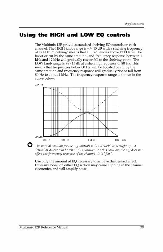
Applications
Multimix 12R Reference Manual 39
Using the HIGH and LOW EQ controls
The Multimix 12R provides standard shelving EQ controls on eachchannel. The HIGH knob range is +/- 15 dB with a shelving frequencyof 12 kHz. "Shelving" means that all frequencies above 12 kHz will beboost or cut by the same amount , and frequency response between 1kHz and 12 kHz will gradually rise or fall to the shelving point. TheLOW knob range is +/- 15 dB at a shelving frequency of 80 Hz. Thismeans that frequencies below 80 Hz will be boosted or cut by thesame amount, and frequency response will gradually rise or fall from80 Hz to about 1 kHz. The frequency response range is shown in thecurve below:
+15 dB
-15 dB 20 Hz 100 Hz 1 kHz 10k 20k
The normal position for the EQ controls is "12 o'clock" or straight up. A"click" or detent will be felt at this position. At this position, the EQ does notaffect the frequency response of the channel--it is "flat".
Use only the amount of EQ necessary to achieve the desired effect.Excessive boost on either EQ section may cause clipping in the channelelectronics, and will amplify noise.
Applications
Monitoring AUX 1 in the PHONES jackIf you are using AUX 1 as a monitor feed, you may want to check thatmix using the headphones. If you've connected the PA or recorder tothe MAIN OUTPUTS, and are not using the TAPE IN jacks, use Y-cordsto connect the AUX 1 SEND to the TAPE IN jack(s) at the same time itfeeds the monitor amplifier. Use the front panel[PHONES/MONITOR] switch to select between the main and aux 1feeds.

Applications
Multimix 12R Reference Manual 39
Using the HIGH and LOW EQ controls
The Multimix 12R provides standard shelving EQ controls on eachchannel. The HIGH knob range is +/- 15 dB with a shelving frequencyof 12 kHz. "Shelving" means that all frequencies above 12 kHz will beboost or cut by the same amount , and frequency response between 1kHz and 12 kHz will gradually rise or fall to the shelving point. TheLOW knob range is +/- 15 dB at a shelving frequency of 80 Hz. Thismeans that frequencies below 80 Hz will be boosted or cut by thesame amount, and frequency response will gradually rise or fall from80 Hz to about 1 kHz. The frequency response range is shown in thecurve below:
+15 dB
-15 dB 20 Hz 100 Hz 1 kHz 10k 20k
The normal position for the EQ controls is "12 o'clock" or straight up. A"click" or detent will be felt at this position. At this position, the EQ does notaffect the frequency response of the channel--it is "flat".
Use only the amount of EQ necessary to achieve the desired effect.Excessive boost on either EQ section may cause clipping in the channelelectronics, and will amplify noise.
Applications
Monitoring AUX 1 in the PHONES jackIf you are using AUX 1 as a monitor feed, you may want to check thatmix using the headphones. If you've connected the PA or recorder tothe MAIN OUTPUTS, and are not using the TAPE IN jacks, use Y-cordsto connect the AUX 1 SEND to the TAPE IN jack(s) at the same time itfeeds the monitor amplifier. Use the front panel[PHONES/MONITOR] switch to select between the main and aux 1feeds.
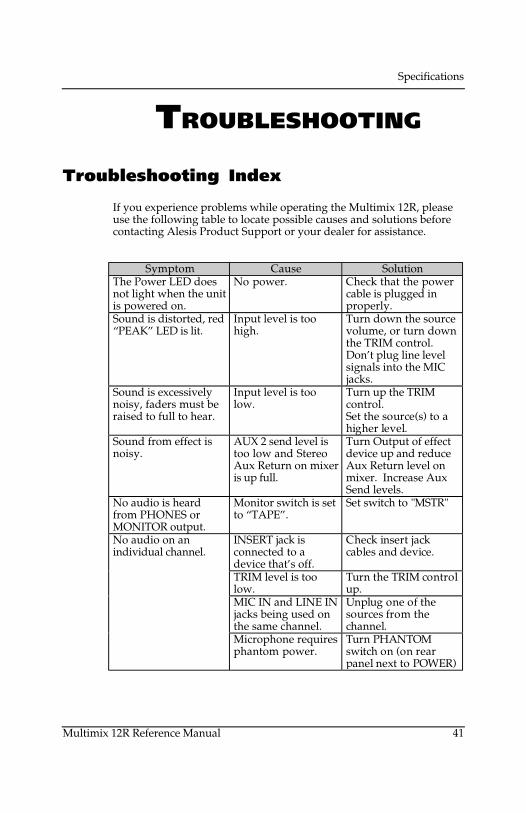
Specifications
Multimix 12R Reference Manual 41
TROUBLESHOOTING
Troubleshooting Index
If you experience problems while operating the Multimix 12R, pleaseuse the following table to locate possible causes and solutions beforecontacting Alesis Product Support or your dealer for assistance.
Symptom Cause SolutionThe Power LED doesnot light when the unitis powered on.
No power. Check that the powercable is plugged inproperly.
Sound is distorted, red“PEAK” LED is lit.
Input level is toohigh.
Turn down the sourcevolume, or turn downthe TRIM control.Don’t plug line levelsignals into the MICjacks.
Sound is excessivelynoisy, faders must beraised to full to hear.
Input level is toolow.
Turn up the TRIMcontrol.Set the source(s) to ahigher level.
Sound from effect isnoisy.
AUX 2 send level istoo low and StereoAux Return on mixeris up full.
Turn Output of effectdevice up and reduceAux Return level onmixer. Increase AuxSend levels.
No audio is heardfrom PHONES orMONITOR output.
Monitor switch is setto “TAPE”.
Set switch to "MSTR"
No audio on anindividual channel.
INSERT jack isconnected to adevice that’s off.
Check insert jackcables and device.
TRIM level is toolow.
Turn the TRIM controlup.
MIC IN and LINE INjacks being used onthe same channel.
Unplug one of thesources from thechannel.
Microphone requiresphantom power.
Turn PHANTOMswitch on (on rearpanel next to POWER)
Specifications
Hum or noise fromoutput.
Ground loop,unshielded cables.
Try plugging the unitinto another powerjack or different audiocables.
No meter, althoughaudio is heard throughmain outputs.
Monitor switch is setto “TAPE”
Set switch to "MSTR"
Crackling sounds. Dirty or corrodingconnections on backof mixer.
Unplug and replugconnectors severaltimes, clean plugs.
A microphone cablehas a small short orbreak.
Unplug themicrophone cablesfrom the mixer untilthe noisy one is found,and replace it.

Specifications
Multimix 12R Reference Manual 43
Maintenance/ServiceExterior cleaning
Disconnect the AC cord, then use a damp cloth to clean the mixer’smetal and plastic surfaces. For heavy dirt, use a non-abrasivehousehold cleaner such as Formula 409 or Fantastik. DO NOT SPRAYTHE CLEANER DIRECTLY ONTO THE FRONT OF THE UNIT AS ITMAY DESTROY THE LUBRICANTS USED IN THE SWITCHES ANDCONTROLS! Spray onto a cloth, then use cloth to clean the unit.
Never spray any kind of cleaner into the faders, even if it claims tobe safe for such use. Such electronic potentiometer cleaners mayimprove performance for a short time, but they cause the fader towear out faster by attracting dirt.
Refer All Servicing to Qualified Technicians
We believe that the Multimix 12R is one of the most reliable mixersthat can be made using current technology, and should provide yearsof trouble-free use. However, should problems occur, DO NOTattempt to service the unit yourself. Service on this product should beperformed only by qualified technicians. NO USER-SERVICEABLEPARTS INSIDE.
Specifications
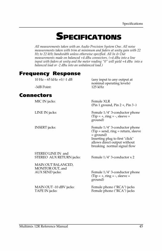
Specifications
Multimix 12R Reference Manual 45
SPECIFICATIONSAll measurements taken with an Audio Precision System One. All noisemeasurements taken with trim at minimum and faders at unity gain with 22Hz to 22 kHz bandwidth unless otherwise specified. All In & Outmeasurements made on balanced +4 dBu connectors. (+4 dBu into a lineinput with faders at unity and the meter reading “0” will yield +4 dBu into abalanced load or -2 dBu into an unbalanced load.)
Frequency Response10 Hz – 65 kHz +0/-1 dB (any input to any output at
nominal operating levels)-3dB Point: 125 kHz
ConnectorsMIC IN jacks: Female XLR
(Pin 1 ground, Pin 2 +, Pin 3 -)
LINE IN jacks: Female 1/4" 3-conductor phone(Tip = +, ring = -, sleeve =ground)
INSERT jacks: Female 1/4" 3-conductor phone(Tip = send, ring = return, sleeve= ground)Inserting plug to first "click"allows direct output withoutbreaking normal signal flow
STEREO LINE IN andSTEREO AUX RETURN jacks: Female 1/4" 3-conductor x 2
MAIN OUT BALANCED,MONITOR OUT, andAUX SEND jacks: Female 1/4" 3-conductor phone
(Tip = +, ring = -, sleeve =ground)
MAIN OUT -10 dBV jacks: Female phono ("RCA") jacksTAPE IN jacks: Female phono ("RCA") jacks
Specifications
LevelsMIC IN -60 dBu to -10 dBu nominal,
maximum level +12 dBuLINE IN -40 dBu to +10 dBu nominal,
maximum level +32 dBu(balanced)
STEREO LINE IN -15 dBu to +15 dBu nominal,maximum input level +22 dBu
MAXIMUM GAIN +76 dB, MIC IN to MAIN OUT,balanced+80 dB, MIC IN to MONITOROUT, balanced or unbalanced
CHANNEL PEAK LED ON: 6 dB below channel clippingMETER: Peak type
-24 dB to PK (+18 dB overreference at MAIN OUT, 6 dBbefore output clipping)
MAIN OUT LEVEL (1/4" phone jacks) (when meter is at 0 VU)+4 dBu (1.24 volts)
into a balanced load-2 dBu into an unbalanced load
MAIN OUT LEVEL (phono jacks) -10 dBV (.316 volts) unbalancedMAXIMUM OUTPUT LEVEL +22 dBu unbalanced, +28 dBu
balanced (6 dB above "PK"segment of main meter)
MONITOR OUT LEVEL Same as above, but variablefollowing MONITOR/PHONEScontrol
INSERT/DIRECT OUT (tip) Unity gainINSERT IN (ring) Maximum level +22 dBuHEADROOM: 23.5 dB above nominal output
ImpedanceMIC IN 50-150 Ω nominal source
impedance (presents 4 k Ωbalanced load impedance)
LINE IN 600 Ω-2 k Ω nominal(>20 k Ω load impedance)
OUTPUTS (MAIN, AUX andMON): 150 Ω unbalanced,
300 Ω balanced1.1 k Ωat -10dBV MAIN OUTS
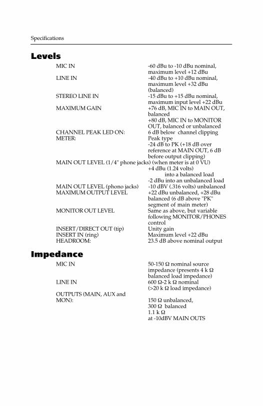
Specifications
Multimix 12R Reference Manual 45
SPECIFICATIONSAll measurements taken with an Audio Precision System One. All noisemeasurements taken with trim at minimum and faders at unity gain with 22Hz to 22 kHz bandwidth unless otherwise specified. All In & Outmeasurements made on balanced +4 dBu connectors. (+4 dBu into a lineinput with faders at unity and the meter reading “0” will yield +4 dBu into abalanced load or -2 dBu into an unbalanced load.)
Frequency Response10 Hz – 65 kHz +0/-1 dB (any input to any output at
nominal operating levels)-3dB Point: 125 kHz
ConnectorsMIC IN jacks: Female XLR
(Pin 1 ground, Pin 2 +, Pin 3 -)
LINE IN jacks: Female 1/4" 3-conductor phone(Tip = +, ring = -, sleeve =ground)
INSERT jacks: Female 1/4" 3-conductor phone(Tip = send, ring = return, sleeve= ground)Inserting plug to first "click"allows direct output withoutbreaking normal signal flow
STEREO LINE IN andSTEREO AUX RETURN jacks: Female 1/4" 3-conductor x 2
MAIN OUT BALANCED,MONITOR OUT, andAUX SEND jacks: Female 1/4" 3-conductor phone
(Tip = +, ring = -, sleeve =ground)
MAIN OUT -10 dBV jacks: Female phono ("RCA") jacksTAPE IN jacks: Female phono ("RCA") jacks
Specifications
LevelsMIC IN -60 dBu to -10 dBu nominal,
maximum level +12 dBuLINE IN -40 dBu to +10 dBu nominal,
maximum level +32 dBu(balanced)
STEREO LINE IN -15 dBu to +15 dBu nominal,maximum input level +22 dBu
MAXIMUM GAIN +76 dB, MIC IN to MAIN OUT,balanced+80 dB, MIC IN to MONITOROUT, balanced or unbalanced
CHANNEL PEAK LED ON: 6 dB below channel clippingMETER: Peak type
-24 dB to PK (+18 dB overreference at MAIN OUT, 6 dBbefore output clipping)
MAIN OUT LEVEL (1/4" phone jacks) (when meter is at 0 VU)+4 dBu (1.24 volts)
into a balanced load-2 dBu into an unbalanced load
MAIN OUT LEVEL (phono jacks) -10 dBV (.316 volts) unbalancedMAXIMUM OUTPUT LEVEL +22 dBu unbalanced, +28 dBu
balanced (6 dB above "PK"segment of main meter)
MONITOR OUT LEVEL Same as above, but variablefollowing MONITOR/PHONEScontrol
INSERT/DIRECT OUT (tip) Unity gainINSERT IN (ring) Maximum level +22 dBuHEADROOM: 23.5 dB above nominal output
ImpedanceMIC IN 50-150 Ω nominal source
impedance (presents 4 k Ωbalanced load impedance)
LINE IN 600 Ω-2 k Ω nominal(>20 k Ω load impedance)
OUTPUTS (MAIN, AUX andMON): 150 Ω unbalanced,
300 Ω balanced1.1 k Ωat -10dBV MAIN OUTS
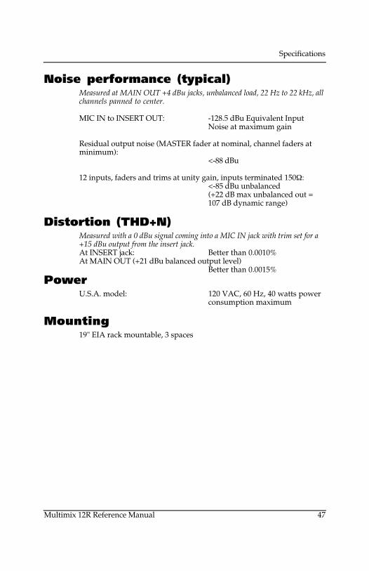
Specifications
Multimix 12R Reference Manual 47
Noise performance (typical)Measured at MAIN OUT +4 dBu jacks, unbalanced load, 22 Hz to 22 kHz, allchannels panned to center.
MIC IN to INSERT OUT: -128.5 dBu Equivalent InputNoise at maximum gain
Residual output noise (MASTER fader at nominal, channel faders atminimum):
<-88 dBu
12 inputs, faders and trims at unity gain, inputs terminated 150Ω:<-85 dBu unbalanced(+22 dB max unbalanced out =107 dB dynamic range)
Distortion (THD+N)Measured with a 0 dBu signal coming into a MIC IN jack with trim set for a+15 dBu output from the insert jack.At INSERT jack: Better than 0.0010%At MAIN OUT (+21 dBu balanced output level)
Better than 0.0015%Power
U.S.A. model: 120 VAC, 60 Hz, 40 watts powerconsumption maximum
Mounting19" EIA rack mountable, 3 spaces
Specifications
DIMENSIONAL DRAWING
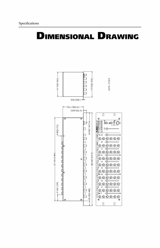
Specifications
Multimix 12R Reference Manual 47
Noise performance (typical)Measured at MAIN OUT +4 dBu jacks, unbalanced load, 22 Hz to 22 kHz, allchannels panned to center.
MIC IN to INSERT OUT: -128.5 dBu Equivalent InputNoise at maximum gain
Residual output noise (MASTER fader at nominal, channel faders atminimum):
<-88 dBu
12 inputs, faders and trims at unity gain, inputs terminated 150Ω:<-85 dBu unbalanced(+22 dB max unbalanced out =107 dB dynamic range)
Distortion (THD+N)Measured with a 0 dBu signal coming into a MIC IN jack with trim set for a+15 dBu output from the insert jack.At INSERT jack: Better than 0.0010%At MAIN OUT (+21 dBu balanced output level)
Better than 0.0015%Power
U.S.A. model: 120 VAC, 60 Hz, 40 watts powerconsumption maximum
Mounting19" EIA rack mountable, 3 spaces
Specifications
DIMENSIONAL DRAWING
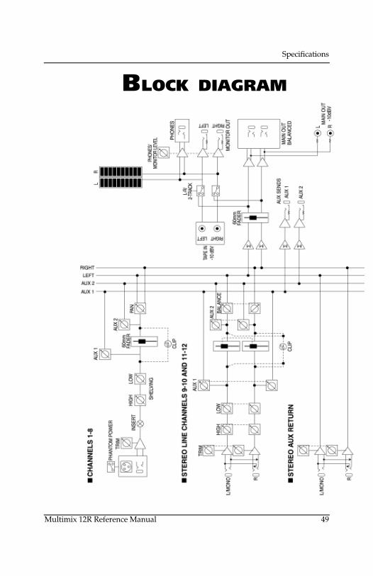
Specifications
Multimix 12R Reference Manual 49
BLOCK DIAGRAM
Specifications
Level diagram
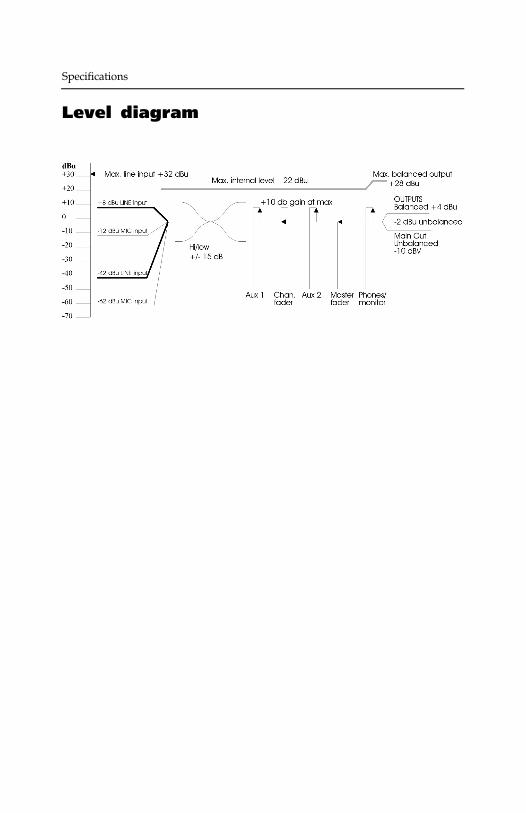
Specifications
Multimix 12R Reference Manual 49
BLOCK DIAGRAM
Specifications
Level diagram
Index
Multimix 12R Reference Manual 51
INDEX
ADAT, 18, 22, 34, 39amplifier, 20, 31Aux 1, 17, 20AUX 2, 16, 32AUX SEND, 16, 20balanced, 12, 20cable, 9clipping, 13compressor, 17direct output
using INSERT jack, 18distortion, 28, 31effect, 16EQ, 31Fader, 30feedback, 20, 21gain, 30ground loop, 35
isolating from rack, 8grounding, 6, 7guitars, 12Headphone, 20, 25headroom, 13, 34, 48HIGH, 41Impedance, 10, 48INSERT cables, 22INSERT jack, 17, 24
in 2-mixer system, 24Levels, 13, 28, 48
diagram, 52LINE IN, 12LOW, 41MAIN OUT -10 dBV, 21MAIN OUT BALANCED, 20Master, 30maximum level, 13, 48meter, 34MIC IN, 10, 13Microphone, 10microphone preamps, 22MONITOR OUT, 14, 20, 25mono, 20MSTR/TAPE switch, 14, 21
affects meter, 34noise, 7, 28, 35, 49nominal, 34PA system, 14, 20PEAK, 28, 34Phantom power, 13
PHONES, 25PHONES/MONITOR, 14, 34phonograph, 15post-fader, 32pre-fader, 17rack, 8, 36reverbb, 16Service, 45shield, 36Specifications, 47stage monitor, 20STEREO AUX RETURN, 16, 32STEREO LINE channels
as Effect Return, 16, 32for CDs and synths, 12maximum input level, 13PEAK LED, 28
TAPE IN, 14as Aux 1 monitor, 42
tape recorder, 21TRIM, 9, 13, 22, 28, 29, 30, 39TRS, 17, 20Unity gain, 30wet/dry, 17, 32XLR, 10, 13

Warranty / Contact
Alesis Limited Warranty ALESIS CORPORATION ("ALESIS") warrants this product to be free of defects in material and workmanship for a period of one (1) year for parts and for a period of one (1) year for labor from the date of original retail purchase. This warranty is enforceable only by the original retail purchaser and cannot be transferred or assigned.
For more effective service and product update notices, please register your Multimix 12R online at: http://www.alesis.com/support/warranty.htm
For the most effective service, the purchaser should register the purchase on the ALESIS website at http://www.alesis.com/support/warranty.htm. During the warranty period ALESIS shall, at its sole and absolute option, either repair or replace free of charge any product that proves to be defective on inspection by ALESIS or its authorized service representative. In all cases disputes concerning this warranty shall be resolved as prescribed by law. To obtain warranty service, the purchaser must first call or write ALESIS at the address and telephone number available on the Alesis Website to obtain a Return Authorization Number and instructions concerning where to return the unit for service. All inquiries must be accompanied by a description of the problem. All authorized returns must be sent to ALESIS or an authorized ALESIS repair facility postage prepaid, insured and properly packaged. Proof of purchase must be presented in the form of a bill of sale, canceled check or some other positive proof that the product is within the warranty period. ALESIS reserves the right to update any unit returned for repair. ALESIS reserves the right to change or improve design of the product at any time without prior notice. This warranty does not cover claims for damage due to abuse, neglect, alteration or attempted repair by unauthorized personnel, and is limited to failures arising during normal use that are due to defects in material or workmanship in the product. THE ABOVE WARRANTIES ARE IN LIEU OF ANY OTHER WARRANTIES OR REPRESENTATIONS WHETHER EXPRESS OR IMPLIED OR OTHERWISE, WITH RESPECT TO THE PRODUCT, AND SPECIFICALLY EXCLUDE ANY IMPLIED WARRANTIES OF FITNESS FOR A PARTICULAR PURPOSE OR MERCHANTABILITY OR OTHER IMPLIED WARRANTIES. Some states do not allow limitations on how long an implied warranty lasts, so the above limitation may not apply to you. IN NO EVENT WILL ALESIS BE LIABLE FOR INCIDENTAL, CONSEQUENTIAL, INDIRECT OR OTHER DAMAGES RESULTING FROM THE BREACH OF ANY EXPRESS OR IMPLIED WARRANTY, INCLUDING, AMONG OTHER THINGS, DAMAGE TO PROPERTY, DAMAGE BASED ON INCONVENIENCE OR ON LOSS OF USE OF THE PRODUCT, AND, TO THE EXTENT PERMITTED BY LAW, DAMAGES FOR PERSONAL INJURY. Some states do not allow the exclusion or limitation of incidental or consequential damages, so the above limitation or exclusion may not apply to you. THIS CONTRACT SHALL BE GOVERNED BY THE INTERNAL LAWS OF THE STATE OF CALIFORNIA WITHOUT REFERENCE TO CONFLICTS OF LAWS. This warranty gives you specific legal rights, and you may also have other rights required by law which vary from state to state. This warranty only applies to products sold to purchasers in the United States of America or Canada. The terms of this warranty and any obligations of Alesis under this warranty shall apply only within the country of sale. Without limiting the foregoing, repairs under this warranty shall be made only by a duly authorized Alesis service representative in the country of sale. For warranty information in all other countries please refer to your local distributor.

Alesis Contact Information Alesis Distribution, LLC Los Angeles, CA USA E-mail: [email protected] Website: http://www.alesis.com Alesis Multimix 12R Reference Manual Revision 1.0 by Brooks Bruner Copyright 2002, Alesis Distribution, LLC. All rights reserved Reproduction in whole or in part is prohibited. “Multimix 12R” is a trademark of Alesis Distribution, LLC. Specifications subject to change without notice. 7-51-0135 10/11/2002