Embed Size (px)
Citation preview

MM3FC Mathematical Modeling 3LECTURE 7
Times
Weeks 7,8 & 9.Lectures : Mon,Tues,Wed 10-11am,
Rm.1439Tutorials : Thurs, 10am, Rm. ULT.
Clinics : Fri, 8am, Rm.4.503Dr. Charles Unsworth,Department of Engineering Science, Rm. 4.611
Tel : 373-7599 ext. 82461Email : [email protected]

This LectureWhat are we going to cover &
Why ?• Connect the z and w-Domains together.
( Allows us to design filters with useful characteristics)
• Zeros and poles of H(z) of a filter.
• Nulling filters. (We can use zeros to null out desired frequencies)
• Bandpass filter. (Allows us to pass desired regions of frequency)
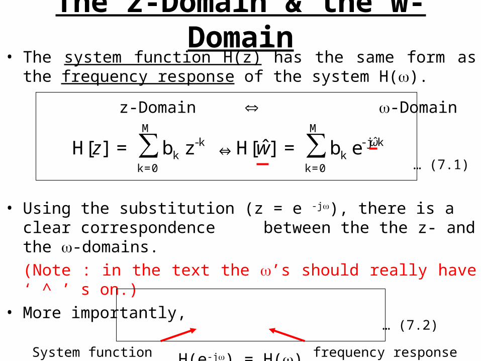
The z-Domain & the w-Domain
• The system function H(z) has the same form as the frequency response of the system H().
z-Domain -Domain
• Using the substitution (z = e -j), there is a clear correspondence between the the z- and the -domains.(Note : in the text the ’s should really have ‘ ^ ’ s on.)
• More importantly,
H(e-j) = H()
∑∑M
0=k
kˆj-k
M
0=k
k-k e b=]ˆ[H⇔z b=][H ωwz
… (7.1)
… (7.2)
System function frequency response
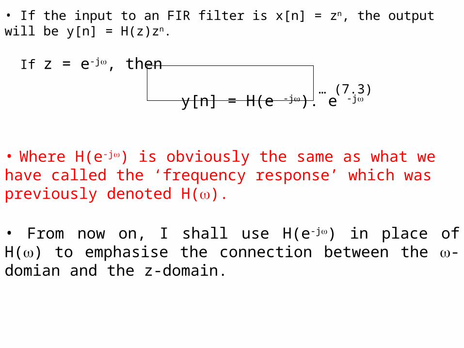
• If the input to an FIR filter is x[n] = zn, the output will be y[n] = H(z)zn.
If z = e-j, then
y[n] = H(e -j). e -j
• Where H(e-j) is obviously the same as what we have called the ‘frequency response’ which was previously denoted H().
• From now on, I shall use H(e-j) in place of H() to emphasise the connection between the -domian and the z-domain.
… (7.3)
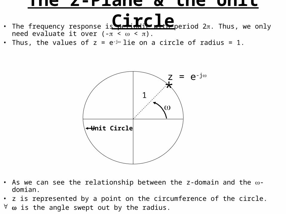
The z-Plane & the Unit Circle• The frequency response is periodic with period 2. Thus, we only
need evaluate it over (- < < ).• Thus, the values of z = e-j lie on a circle of radius = 1.
• As we can see the relationship between the z-domain and the -domian.
• z is represented by a point on the circumference of the circle. is the angle swept out by the radius.
1 *z = e-j
Unit Circle
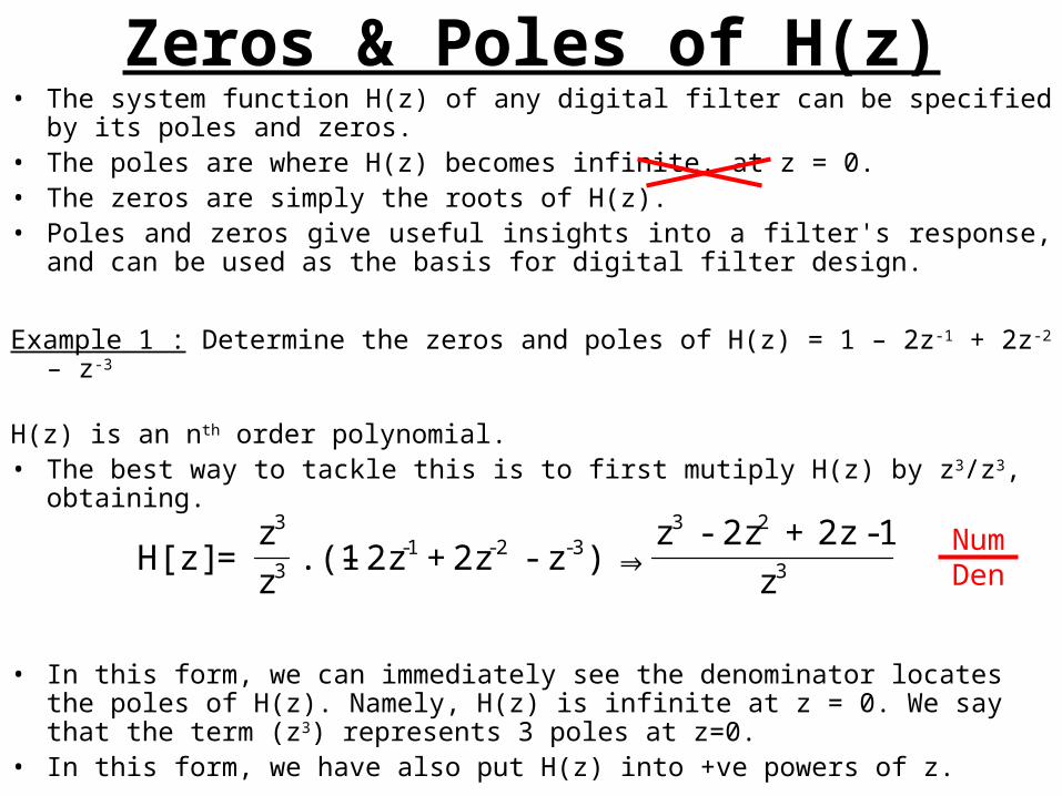
Zeros & Poles of H(z)• The system function H(z) of any digital filter can be specified by its
poles and zeros.• The poles are where H(z) becomes infinite. at z = 0.• The zeros are simply the roots of H(z).• Poles and zeros give useful insights into a filter's response, and can
be used as the basis for digital filter design.
Example 1 : Determine the zeros and poles of H(z) = 1 – 2z-1 + 2z-2 – z-3
H(z) is an nth order polynomial. • The best way to tackle this is to first mutiply H(z) by z3/z3, obtaining.
• In this form, we can immediately see the denominator locates the poles of H(z). Namely, H(z) is infinite at z = 0. We say that the term (z3) represents 3 poles at z=0.
• In this form, we have also put H(z) into +ve powers of z.
3
233-2-1-
3
3
z
1 -2z+2z-z⇒)z-2z + 2z– .(1
z
z=H[z]
NumDen
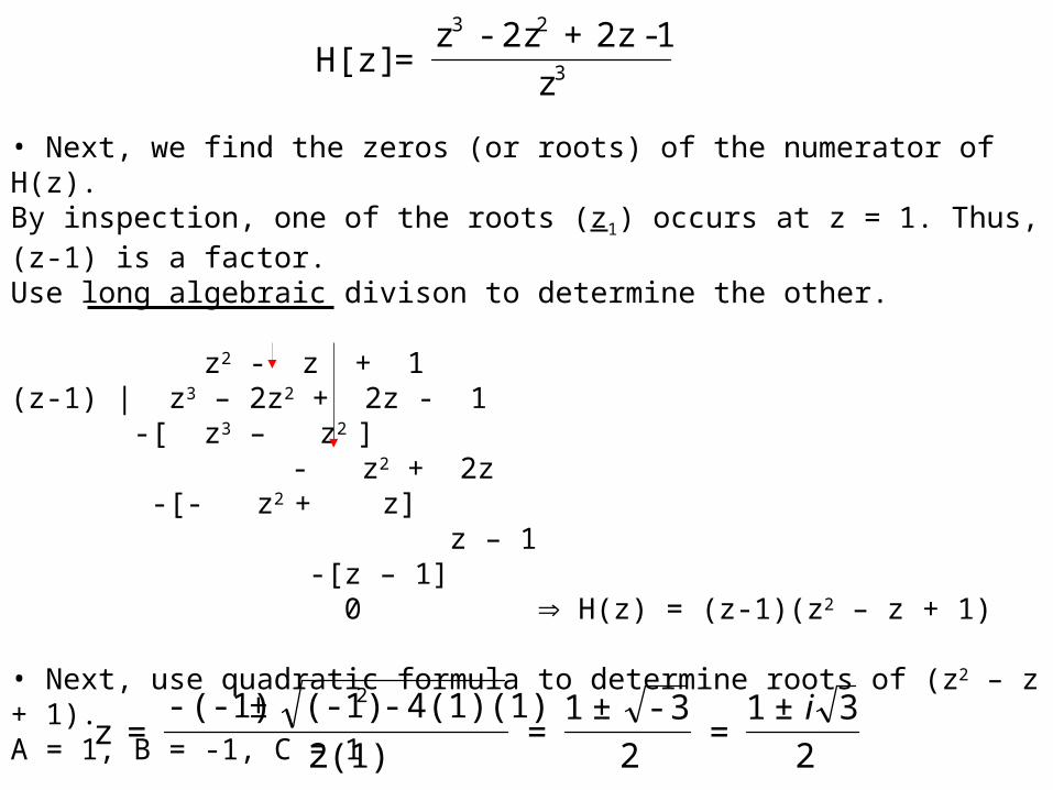
• Next, we find the zeros (or roots) of the numerator of H(z).By inspection, one of the roots (z1) occurs at z = 1. Thus, (z-1) is a factor.Use long algebraic divison to determine the other.
z2 - z + 1(z-1) | z3 – 2z2 + 2z - 1 -[ z3 – z2 ] - z2 + 2z
-[- z2 + z] z – 1
-[z – 1] 0 H(z) = (z-1)(z2 – z + 1)
• Next, use quadratic formula to determine roots of (z2 – z + 1).A = 1, B = -1, C = 1
3
23
z
1 -2z+2z-z=H[z]
2
3±1=
2
3-±1=
2(1)
4(1)(1)-(-1)± (-1)-=z
2 i
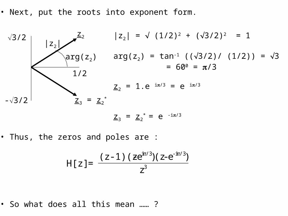
• Next, put the roots into exponent form.
• Thus, the zeros and poles are :
• So what does all this mean …… ?
|z2| = (1/2)2 + (3/2)2 = 1
arg(z2) = tan-1 ((3/2)/ (1/2)) = 3 = 600 = /3
z2 = 1.e i/3 = e i/3
z3 = z2* = e -i/3
3/2
-3/2
1/2
|z2|
arg(z2)
z2
z3 = z2*
3
/3i -/3i
z
)e - (z)e - 1)(z-(z=H[z]
ππ
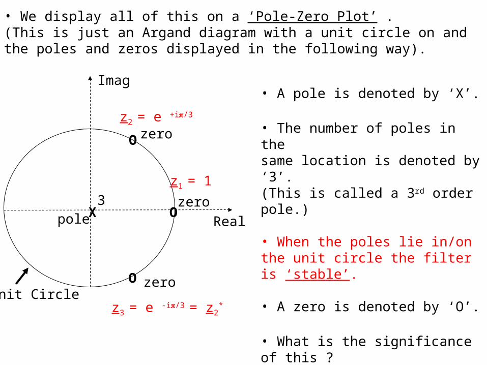
• We display all of this on a ‘Pole-Zero Plot’ .(This is just an Argand diagram with a unit circle on and the poles and zeros displayed in the following way).
Imag
RealX
3O
O
O
pole
zero
zero
zero
• A pole is denoted by ‘X’.
• The number of poles in thesame location is denoted by ‘3’.(This is called a 3rd order pole.)
• When the poles lie in/on the unit circle the filter is ‘stable’.
• A zero is denoted by ‘O’.
• What is the significance of this ?
• The zero’s actually tell us which frequencies the filter ‘blocks’ or ‘nulls’ or ‘cancels’ out. ( i.e where, y[n] = 0 ).
Unit Circle
z2 = e +i/3
z3 = e -i/3 = z2
*
z1 = 1
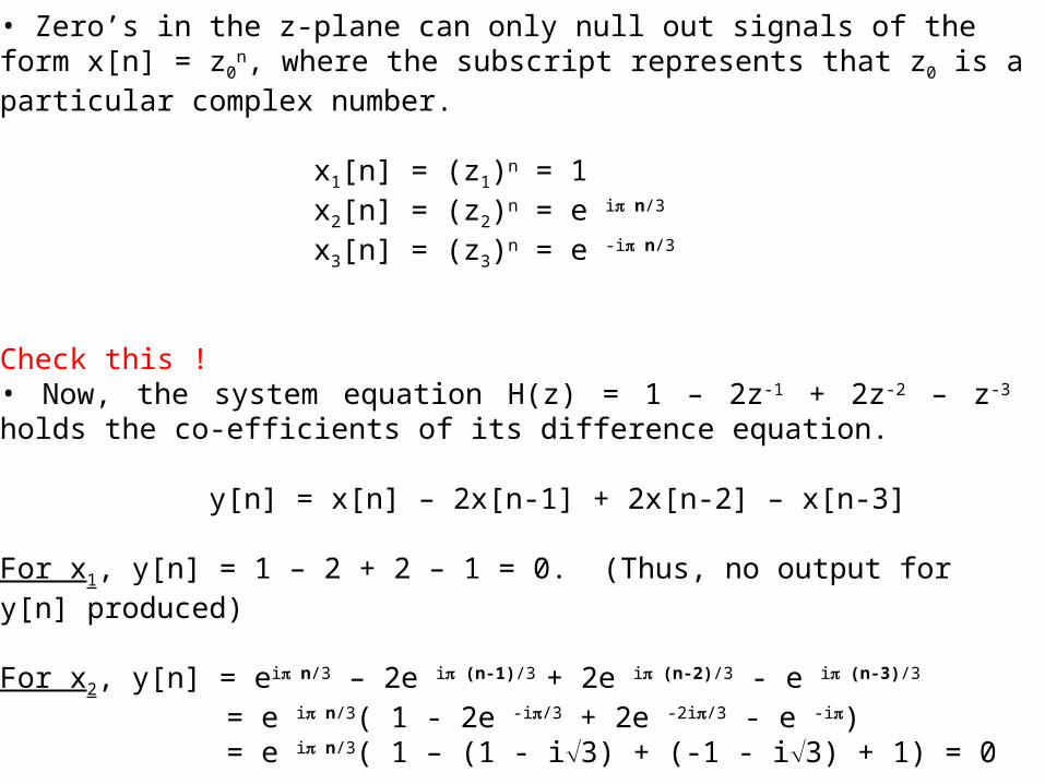
• Zero’s in the z-plane can only null out signals of the form x[n] = z0n,
where the subscript represents that z0 is a particular complex number.
x1[n] = (z1)n = 1x2[n] = (z2)n = e i n/3 x3[n] = (z3)n = e -i n/3
Check this !• Now, the system equation H(z) = 1 – 2z-1 + 2z-2 – z-3 holds the co-efficients of its difference equation.
y[n] = x[n] – 2x[n-1] + 2x[n-2] – x[n-3]
For x1, y[n] = 1 – 2 + 2 – 1 = 0. (Thus, no output for y[n] produced)
For x2, y[n] = ei n/3 – 2e i (n-1)/3 + 2e i (n-2)/3 - e i (n-3)/3
= e i n/3( 1 - 2e -i/3 + 2e -2i/3 - e -i) = e i n/3( 1 – (1 - i3) + (-1 - i3) + 1) = 0
x3 is the complex conjugate of x2 and y[n] = 0.
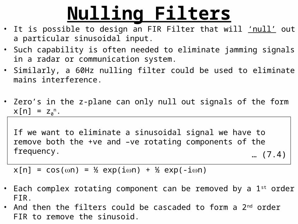
Nulling Filters• It is possible to design an FIR Filter that will ‘null’ out a particular
sinusoidal input.• Such capability is often needed to eliminate jamming signals in a
radar or communication system.• Similarly, a 60Hz nulling filter could be used to eliminate mains
interference.
• Zero’s in the z-plane can only null out signals of the form x[n] = z0
n.
If we want to eliminate a sinusoidal signal we have to remove both the +ve and –ve rotating components of the frequency.
x[n] = cos(n) = ½ exp(in) + ½ exp(-in)
• Each complex rotating component can be removed by a 1st order FIR.
• And then the filters could be cascaded to form a 2nd order FIR to remove the sinusoid.
… (7.4)
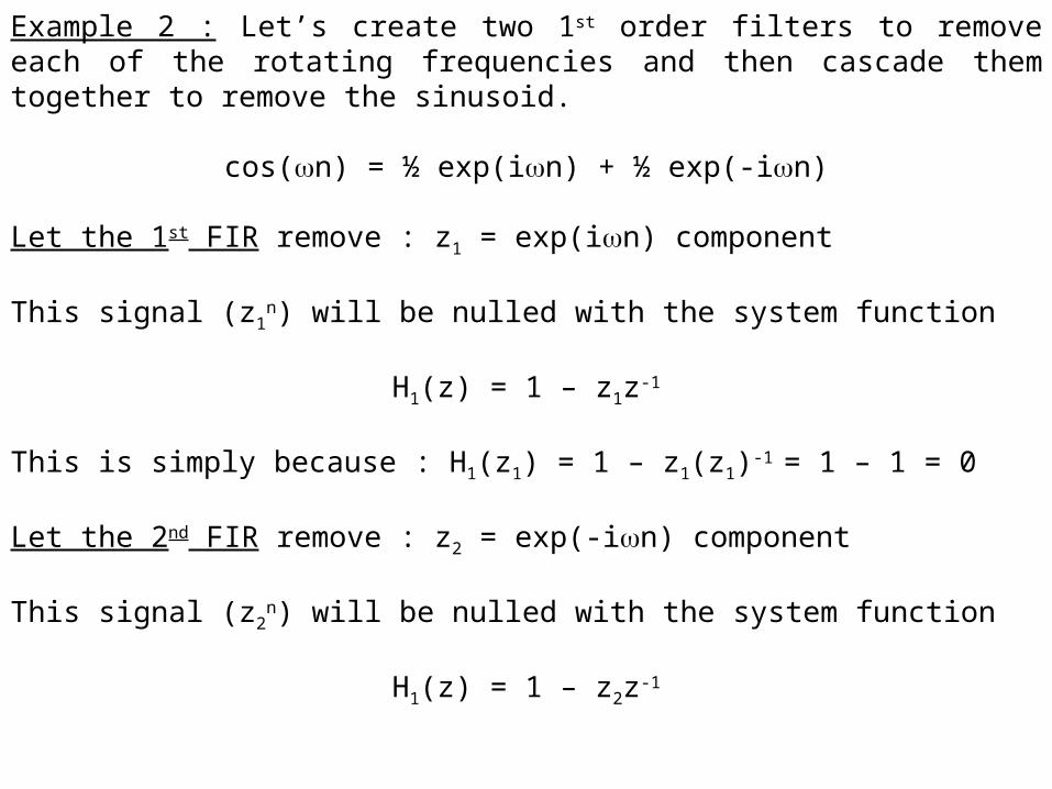
Example 2 : Let’s create two 1st order filters to remove each of the rotating frequencies and then cascade them together to remove the sinusoid.
cos(n) = ½ exp(in) + ½ exp(-in)
Let the 1st FIR remove : z1 = exp(in) component
This signal (z1n) will be nulled with the system function
H1(z) = 1 – z1z-1
This is simply because : H1(z1) = 1 – z1(z1)-1 = 1 – 1 = 0
Let the 2nd FIR remove : z2 = exp(-in) component
This signal (z2n) will be nulled with the system function
H1(z) = 1 – z2z-1
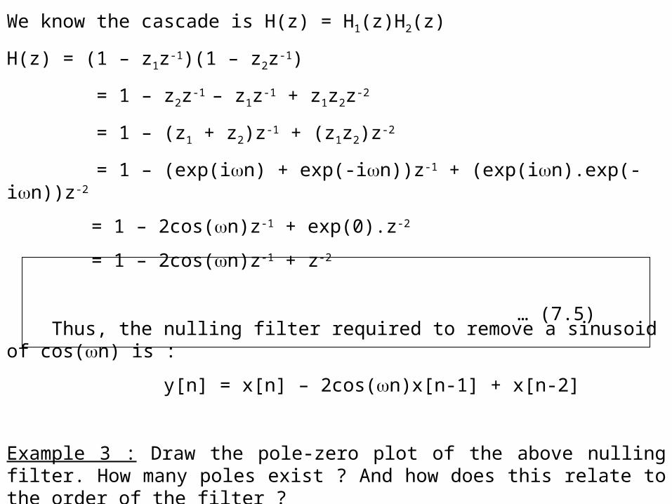
We know the cascade is H(z) = H1(z)H2(z)
H(z) = (1 – z1z-1)(1 – z2z-1)
= 1 – z2z-1 – z1z-1 + z1z2z-2
= 1 – (z1 + z2)z-1 + (z1z2)z-2
= 1 – (exp(in) + exp(-in))z-1 + (exp(in).exp(-in))z-2
= 1 – 2cos(n)z-1 + exp(0).z-2
= 1 – 2cos(n)z-1 + z-2
Thus, the nulling filter required to remove a sinusoid of cos(n) is :
y[n] = x[n] – 2cos(n)x[n-1] + x[n-2]
Example 3 : Draw the pole-zero plot of the above nulling filter. How many poles exist ? And how does this relate to the order of the filter ?
… (7.5)
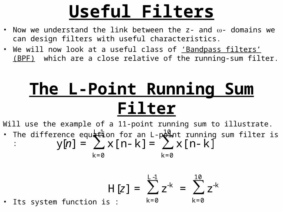
Useful Filters• Now we understand the link between the z- and - domains we can
design filters with useful characteristics.• We will now look at a useful class of ‘Bandpass filters’ (BPF) which
are a close relative of the running-sum filter.
The L-Point Running Sum Filter
Will use the example of a 11-point running sum to illustrate.• The difference equation for an L-point running sum filter is :
• Its system function is :
∑∑10
0=k
1-L
0=k
k]-x[n=k]-x[n=][y n
∑∑10
0=k
k-1-L
0=k
k- z=z=][H z
α
αα
-1
-1=
L1-L
0=k
k∑
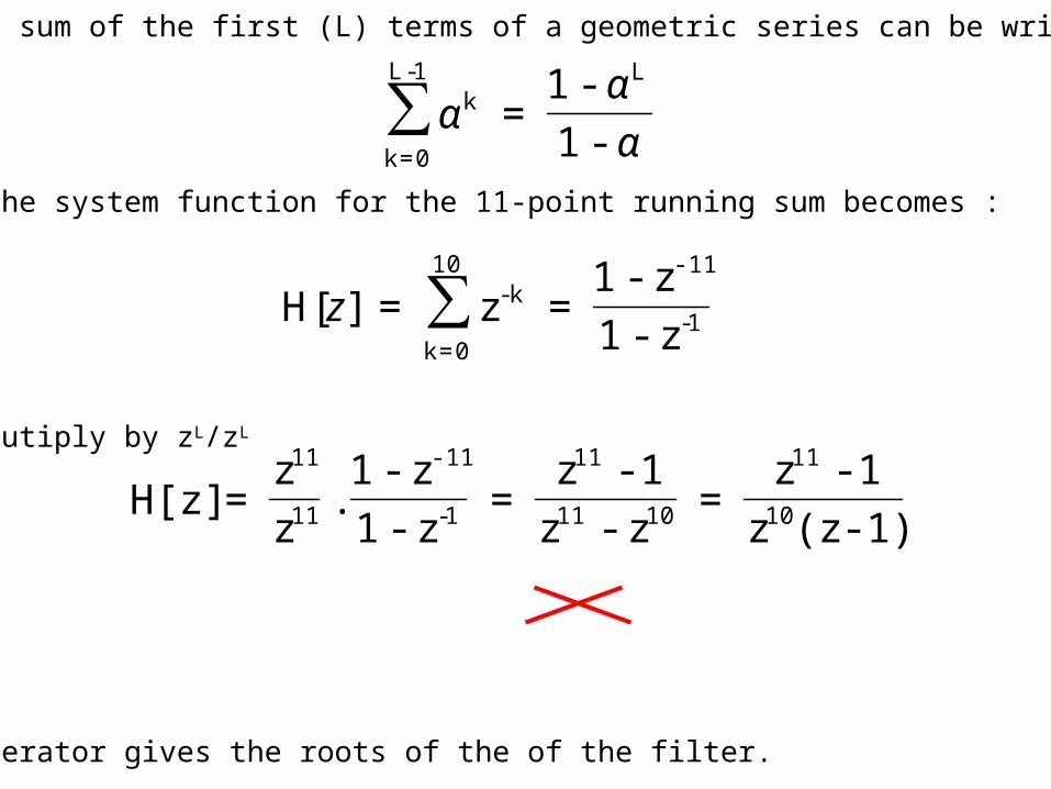
• Now the sum of the first (L) terms of a geometric series can be wriiten as :
• Thus, the system function for the 11-point running sum becomes :
• First mutiply by zL/zL
• The numerator gives the roots of the of the filter.
Thus, we have roots at z11 – 1 = 0 z11 = 1
• We have to use ‘nth Roots of Unity’ to solve this.
1-
-1110
0=k
k-
z-1
z-1=z=][H ∑z
1)-(zz
1-z=
z-z
1-z=
z-1
z-1.
z
z=H[z] 10
11
1011
11
1-
-11
11
11
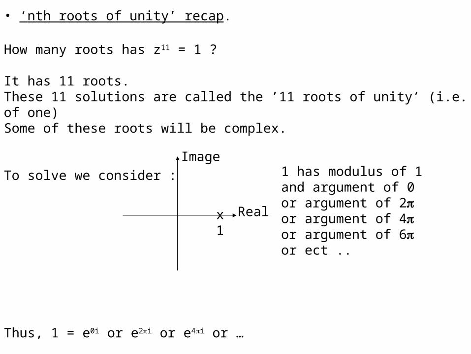
• ‘nth roots of unity’ recap.
How many roots has z11 = 1 ?
It has 11 roots. These 11 solutions are called the ’11 roots of unity’ (i.e. of one)Some of these roots will be complex.
To solve we consider :
Thus, 1 = e0i or e2i or e4i or …
x1
Image
Real
1 has modulus of 1and argument of 0or argument of 2or argument of 4or argument of 6or ect ..
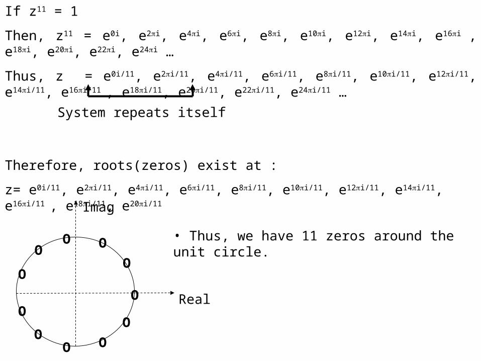
If z11 = 1
Then, z11 = e0i, e2i, e4i, e6i, e8i, e10i, e12i, e14i, e16i , e18i, e20i, e22i, e24i …
Thus, z = e0i/11, e2i/11, e4i/11, e6i/11, e8i/11, e10i/11, e12i/11, e14i/11, e16i/11 , e18i/11, e20i/11, e22i/11, e24i/11 …
Therefore, roots(zeros) exist at :
z= e0i/11, e2i/11, e4i/11, e6i/11, e8i/11, e10i/11, e12i/11, e14i/11, e16i/11 , e18i/11, e20i/11
System repeats itself
Imag
RealO
O
OO
O
O
O
O
O
O
O
• Thus, we have 11 zeros around the unit circle.
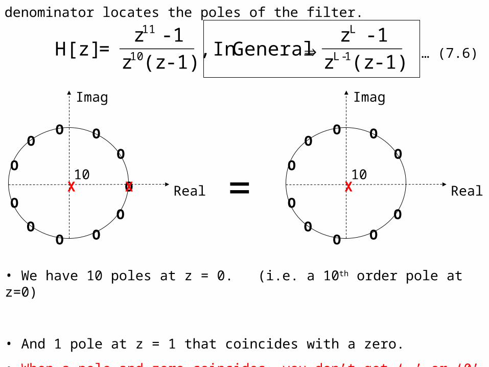
• We have 10 poles at z = 0. (i.e. a 10th order pole at z=0)
• And 1 pole at z = 1 that coincides with a zero.
• When a pole and zero coincides, you don’t get ‘’ or ‘0’ but a finite value.
Imag
RealX10
O
O
OO
O
O
O
O
O
O
O
X
• The denominator locates the poles of the filter.
1)-(zz
1-z⇒ GeneralIn ,
1)-(zz
1-z=H[z] 1-L
L
10
11
Imag
RealX10
O
OO
O
O
O
O
O
O
O
=
… (7.6)
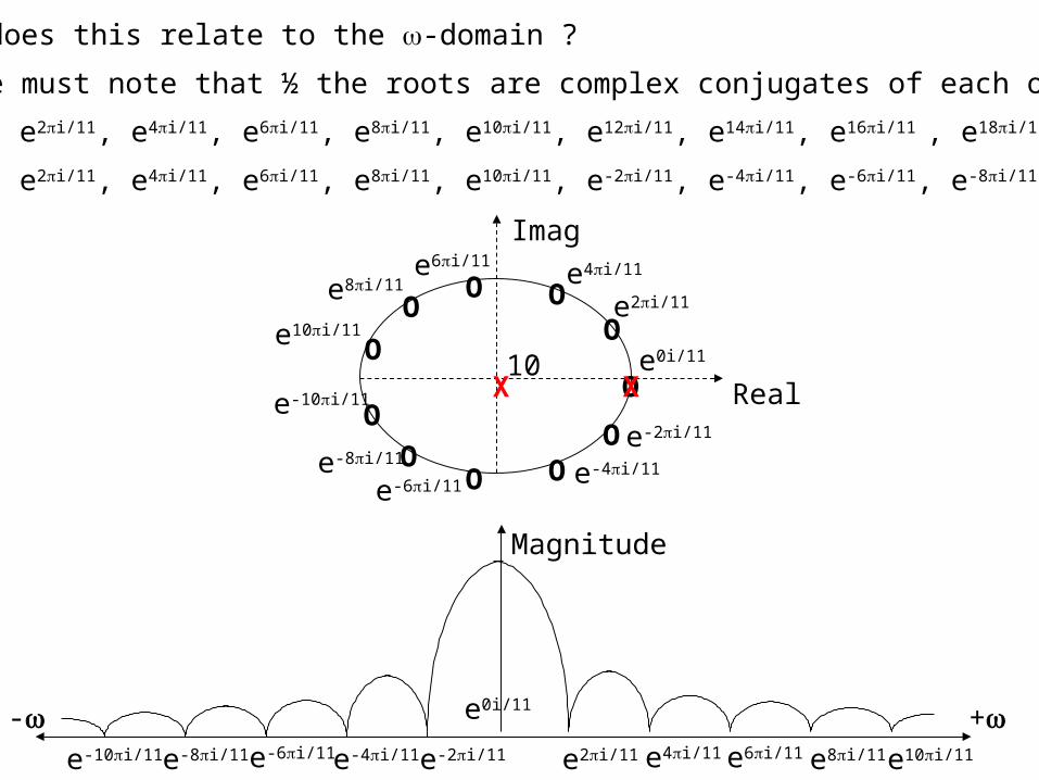
• What does this relate to the -domain ?
First we must note that ½ the roots are complex conjugates of each other.
z= e0i/11, e2i/11, e4i/11, e6i/11, e8i/11, e10i/11, e12i/11, e14i/11, e16i/11 , e18i/11, e20i/11
z= e0i/11, e2i/11, e4i/11, e6i/11, e8i/11, e10i/11, e-2i/11, e-4i/11, e-6i/11, e-8i/11, e-10i/11
e-6i/11
Imag
RealX10
O
OOO
O
O
OO
OO
O
Xe0i/11
e2i/11
e-2i/11
e4i/11
e-4i/11
e6i/11
e8i/11
e-8i/11
e10i/11
e-10i/11
+-
Magnitude
e0i/11
e2i/11e-2i/11 e4i/11e-4i/11 e6i/11e-6i/11 e8i/11e-8i/11 e10i/11e-10i/11

+-
Magnitude
e0i/11
e2i/11e-2i/11 e4i/11e-4i/11 e6i/11e-6i/11 e8i/11e-8i/11 e10i/11e-10i/11
e-2i/11 + e-2i/11 = 2cos(2/11) Rejected
Rejected sinusoids
+-
Magnitude
e0i/11
e2i/11e-2i/11 e4i/11e-4i/11 e6i/11e-6i/11 e8i/11e-8i/11 e10i/11e-10i/11
Pass band
Frequencies preserved
Side-lobes
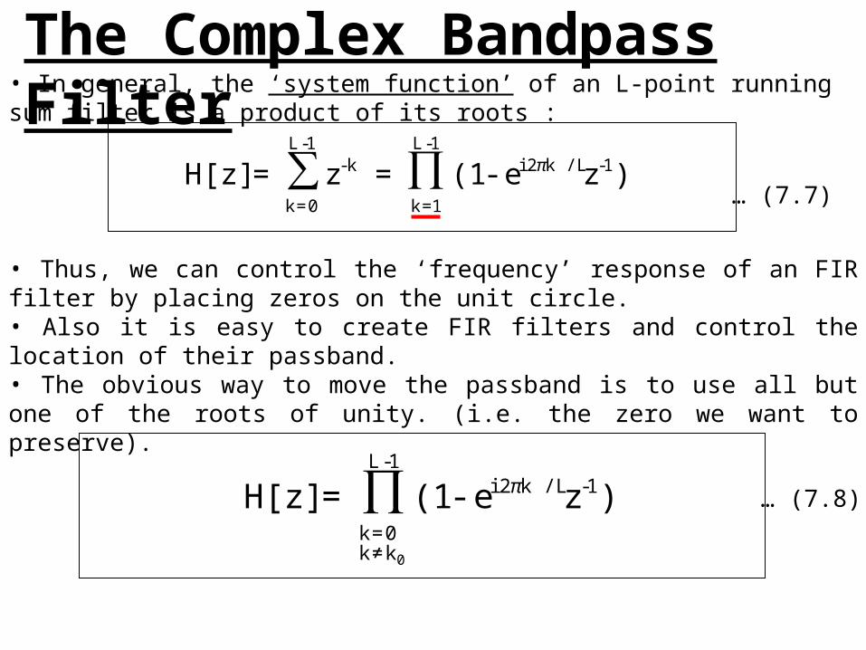
• In general, the ‘system function’ of an L-point running sum filter is a product of its roots :
• Thus, we can control the ‘frequency’ response of an FIR filter by placing zeros on the unit circle.• Also it is easy to create FIR filters and control the location of their passband.• The obvious way to move the passband is to use all but one of the roots of unity. (i.e. the zero we want to preserve).
Where, the index k0 denotes the omitted root at z = exp(i2k0/L).
)z e-(1=z=H[z] ∏∑1-L
1=k
1-k /L2 i1-L
0=k
k- π
)z e-(1=H[z] ∏1-L
k≠k0=k
1-k /L2 i
0
π
The Complex Bandpass Filter
… (7.7)
… (7.8)
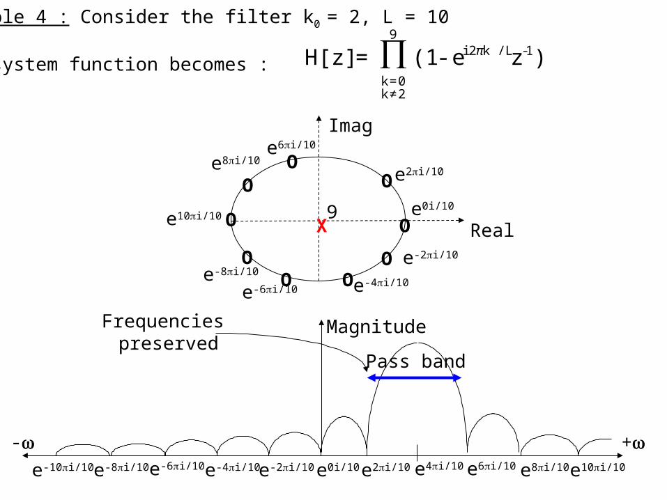
Example 4 : Consider the filter k0 = 2, L = 10
The system function becomes :
+-
Magnitude
e0i/10 e2i/10e-2i/10 e4i/10e-4i/10 e6i/10e-6i/10 e8i/10e-8i/10 e10i/10
Pass band
Frequencies preserved
)z e-(1=H[z] ∏9
2≠k0=k
1-k /L2 i π
e-6i/10
Imag
RealX9
O
OO
O
O
OO O
e0i/10
e2i/10
e-2i/10
e6i/10
e8i/10
e-8i/10
e10i/10
Oe-4i/10
e-10i/10
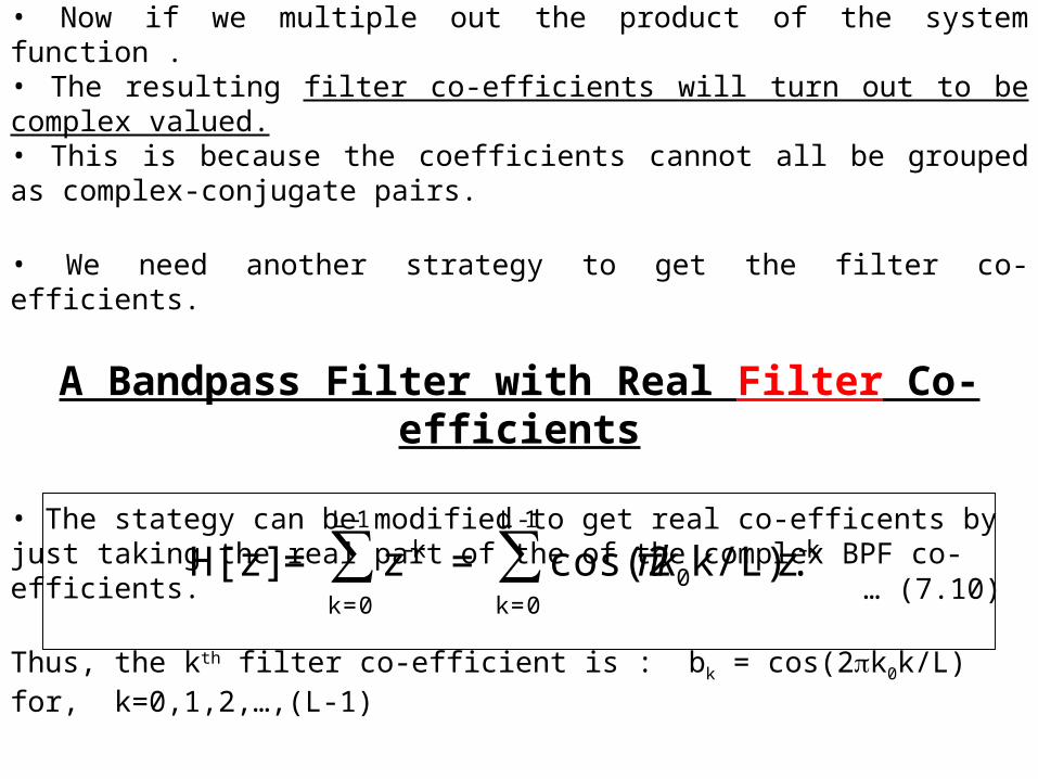
• Now if we multiple out the product of the system function .• The resulting filter co-efficients will turn out to be complex valued. • This is because the coefficients cannot all be grouped as complex-conjugate pairs.
• We need another strategy to get the filter co-efficients.
A Bandpass Filter with Real Filter Co-efficients
• The stategy can be modified to get real co-efficents by just taking the real part of the of the complex BPF co-efficients.
Thus, the kth filter co-efficient is : bk = cos(2k0k/L) for, k=0,1,2,…,(L-1)
• Now expanding using Eulers Inverse Formulae.
∑∑1-L
0=k
k-0
1-L
0=k
k- z k/L).cos(2=z=H[z] kπ… (7.10)
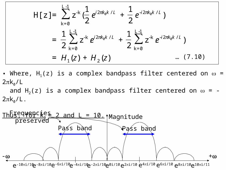
)(+)(=
).z2
1+.z
2
1=
)2
1+
2
1(z=H[z]
21
/2-1-L
0=k
k-/21-L
0=k
k-
/2-/21-L
0=k
k-
00
00
∑∑
∑
zHzH
ee
ee
LkkiLkki
LkkiLkki
ππ
ππ
• Where, H1(z) is a complex bandpass filter centered on = 2k0/L and H2(z) is a complex bandpass filter centered on = -2k0/L.
Thus, for k0 = 2 and L = 10.
+-
Magnitude
e0i/10 e2i/10e-2i/10 e4i/10e-4i/10 e6i/10e-6i/10 e8i/10e-8i/10 e10i/11
Pass band
Frequencies preserved
e-10i/10
Pass band
… (7.10)

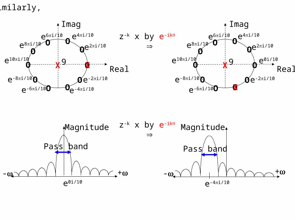
How is this so ?Multiplying the (z-k) ‘s in the z-plane by the factors (eik) & (e-ik) will result in a rotation of the pole-zero plot by an angle ().
e-6i/10
Imag
RealX9
OO
O
O
OO O
e2i/10
e-2i/10
e6i/10
e8i/10
e-8i/10
e10i/10
Oe-4i/10 e-6i/10
Imag
RealX9 O
OO
O
O
OO O
e0i/10
e2i/10
e-2i/10
e6i/10
e8i/10
e-8i/10
e10i/10
Oe-4i/10
Oe4i/10 z-k x by e+ik
+-
Magnitude
e0i/10
Pass band
z-k x by e+ik
+-
Magnitude
Pass band
e4i/10
OX
OX
e10i/10
e-6i/10
Imag
RealX9 O
OO
O
O
OO O
e0i/10
e2i/10
e-2i/10
e6i/10
e8i/10
e-8i/10
Oe4i/10
e-6i/10
Imag
RealX9
OO
O
O
OO O
e2i/10
e-2i/10
e6i/10
e8i/10
e-8i/10
e10i/10
Oe-4i/10
Oe4i/10 z-k x by e-ik
+-
Magnitude
e0i/10
Pass band
z-k x by e-ik
- +
Magnitude
Pass band
e-4i/10
Similarly,
OX
OX
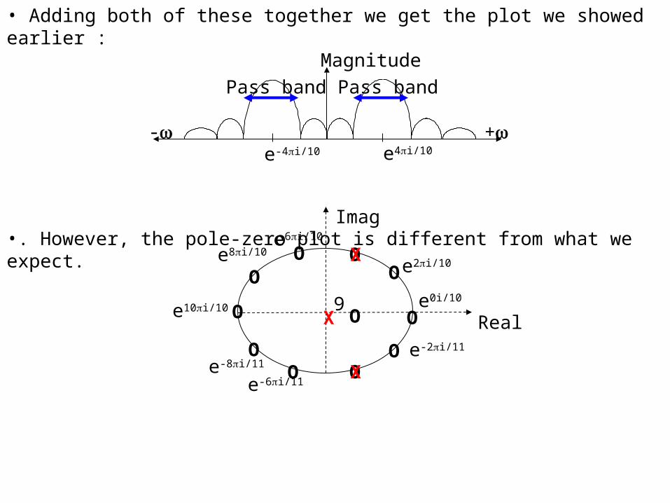
• Adding both of these together we get the plot we showed earlier :
•. However, the pole-zero plot is different from what we expect.
• We have introduced 2 poles to cancel out the roots at z = e-4i/10 & e4i/10.• These have been replaced by a single real zero at z = cos(2k0/L) = 0.309 which is the real part of the missing zeros. • How do we gets this additional zero occurring ?
+-
Magnitude
e4i/10e-4i/10
Pass bandPass band
e-6i/11
Imag
RealX9
O
OO
O
O
OO O
e0i/10
e2i/10
e-2i/11
e6i/10
e8i/10
e-8i/11
e10i/10O
OX
OX
10/4-9
0=k
k-10/49
0=k
k- .z2
1+.z
2
1=H[z] ∑∑ ππ ii ee
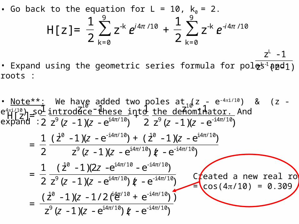
• Go back to the equation for L = 10, k0 = 2.
• Expand using the geometric series formula for poles and roots :
• Note**: We have added two poles at (z - e-4i/10) & (z - e4i/10) so introduce these into the denominator. And expand :
1)-(zz
1-z1-L
L
)e-)(e-(1)-(z
))e+1/2(e -(1)-(z=
)e-)(e-(1)-(z
)e-e -2(1)-(z
2
1=
)e-)(e-(1)-(z
)e-(1)-(z+)e-(1)-(z
2
1=
)e-(1)-(z
1-z
2
1+
)e-(1)-(z
1-z
2
1=H[z]
/104 i-/104 i9
/104 i-/104 i10
/104 i-/104 i9
/104 i-/104 i10
/104 i-/104 i9
/104 i10/104 i-10
/104 i-9
10
/104 i9
10
ππ
ππ
ππ
ππ
ππ
ππ
ππ
zzz
z
zzz
z
zzz
zz
zzzz
Created a new real root= cos(4/10) = 0.309
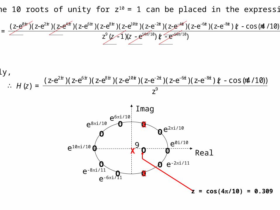
• Now the 10 roots of unity for z10 = 1 can be placed in the expression.
• Finally,
• Phew …… !!!
)e-)(e-(1)-(z
))10/cos(4 -)(e - (z)e - (z)e - (z)e - (z)e - (z)e - (z)e - (z)e - (z)e - (z)e - (z= /104 i-/104 i9
-8i-6i-4i-2i10i8i6i4i2i0i
ππ
ππππππππππ π
zzz
z
9
-8i-6i-2i10i8i6i2i
z
))10/cos(4 -)(e - (z)e - (z)e - (z)e - (z)e - (z)e - (z)e - (z=)(∴
ππππππππ zzH
e-6i/11
Imag
RealX9
O
OO
O
O
OO O
e0i/10
e2i/10
e-2i/11
e6i/10
e8i/10
e-8i/11
e10i/10O
OX
OX
z = cos(4/10) = 0.309