Embed Size (px)
Citation preview
Safety ManualMMI-20029788, Rev AB
September 2015
Coriolis Flowmeter with Micro Motion®
Model 5700 Transmitters
Safety Manual for Safety Instrumented Systems (SIS)
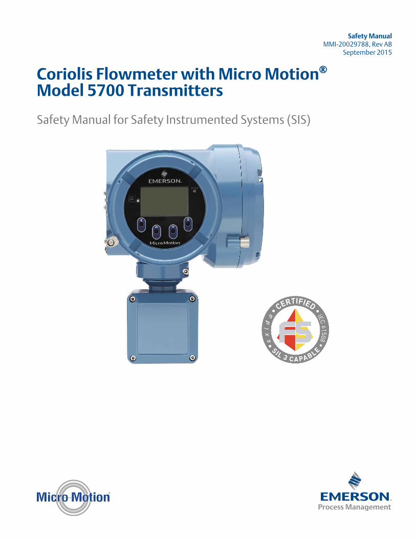
Emerson Flow customer service
Email:
• Worldwide: [email protected]
• Asia-Pacific: [email protected]
Telephone:
North and South America Europe and Middle East Asia Pacific
United States 800-522-6277 U.K. 0870 240 1978 Australia 800 158 727
Canada +1 303-527-5200 The Netherlands +31 (0) 704 136 666 New Zealand 099 128 804
Mexico +41 (0) 41 7686 111 France 0800 917 901 India 800 440 1468
Argentina +54 11 4837 7000 Germany 0800 182 5347 Pakistan 888 550 2682
Brazil +55 15 3413 8000 Italy 8008 77334 China +86 21 2892 9000
Venezuela +58 26 1731 3446 Central & Eastern +41 (0) 41 7686 111 Japan +81 3 5769 6803
Russia/CIS +7 495 981 9811 South Korea +82 2 3438 4600
Egypt 0800 000 0015 Singapore +65 6 777 8211
Oman 800 70101 Thailand 001 800 441 6426
Qatar 431 0044 Malaysia 800 814 008
Kuwait 663 299 01
South Africa 800 991 390
Saudi Arabia 800 844 9564
UAE 800 0444 0684
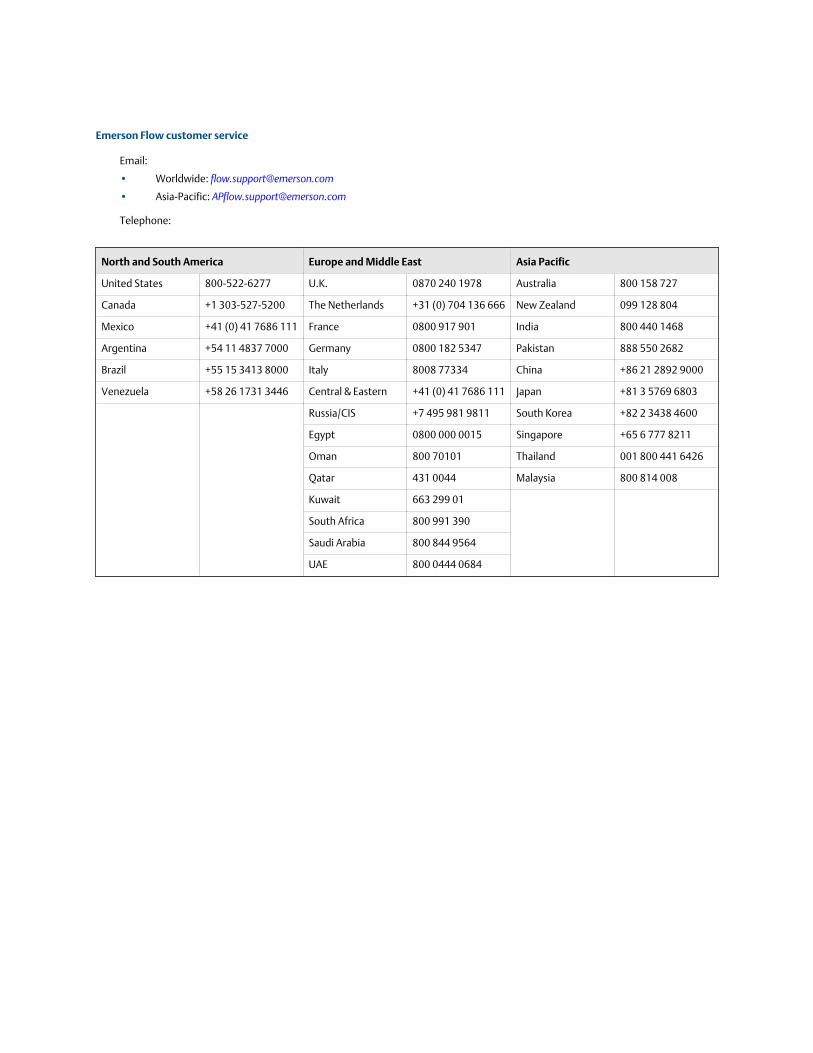
Contents
Chapter 1 Before you begin .............................................................................................................. 11.1 About this document ..................................................................................................................... 11.2 Related documents ........................................................................................................................ 1
Chapter 2 Installation and commissioning ........................................................................................32.1 Set up the Model 5700 ................................................................................................................... 42.2 Diagnostics .................................................................................................................................... 82.3 Enable write-protection on the transmitter configuration .............................................................. 82.4 Update the firmware .................................................................................................................... 102.5 Replace equipment ...................................................................................................................... 12
Chapter 3 Proof tests ......................................................................................................................133.1 Proof test options .........................................................................................................................133.2 Proof test 1 ...................................................................................................................................143.3 Proof test 2 ...................................................................................................................................153.4 Proof test 3 ...................................................................................................................................16
Chapter 4 Operating constraints .................................................................................................... 194.1 Reliability data ..............................................................................................................................194.2 Report failures ..............................................................................................................................19
Contents
Safety Manual for Safety Instrumented Systems (SIS) i

Contents
ii Micro Motion® Model 5700 transmitters
1 Before you beginTopics covered in this chapter:
• About this document
• Related documents
1.1 About this documentThis document provides information about how to install, commission, and proof test aCoriolis flowmeter with a Model 5700 transmitter to comply with Safety InstrumentedSystems (SIS) requirements.
The information in this document assumes that users understand:
• Basic transmitter and sensor installation, configuration, and maintenance conceptsand procedures
• Safety Instrumented System (SIS) operations, including bypass procedures,flowmeter maintenance, and company Management of Change procedures
• All corporate, local government, and national government safety standards andrequirements that guard against injuries or death
1.2 Related documentsYou can find all product documentation via the Micro Motion product documentation DVDshipped with the product or at www.micromotion.com.
For more information, see any of the following documents:
• Micro Motion Model 5700 Product Data Sheet
• Micro Motion Model 5700 Transmitters Installation Manual
• Micro Motion Model 5700 Transmitters Configuration and Use Manual
• Micro Motion sensor installation and configuration and use manuals
• Micro Motion sensor product data sheets
• Report No. MiMo 14/02-064 R001; FMEDA report for Coriolis Flowmeter with 5700Transmitter, Prepared for Micro Motion by exida.com LLC
Before you begin
Safety Manual for Safety Instrumented Systems (SIS) 1

Before you begin
2 Micro Motion® Model 5700 transmitters
2 Installation and commissioningTopics covered in this chapter:
• Set up the Model 5700
• Diagnostics
• Enable write-protection on the transmitter configuration
• Update the firmware
• Replace equipment
Use this section to install and commission a Coriolis flowmeter with a Model 5700transmitter with SIS features.
IEC 61508 relevant requirements
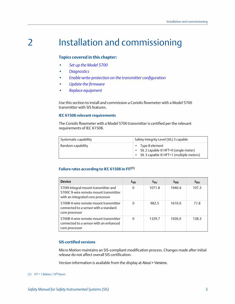
The Coriolis flowmeter with a Model 5700 transmitter is certified per the relevantrequirements of IEC 61508.
Systematic capability Safety Integrity Level (SIL) 3 capable
Random capability • Type B element• SIL 2 capable @ HFT=0 (single meter)• SIL 3 capable @ HFT=1 (multiple meters)
Failure rates according to IEC 61508 in FIT(1)
Device λSD λSU λDD λDU
5700I Integral mount transmitter and5700C 9-wire remote mount transmitterwith an integrated core processor
0 1071.8 1940.4 107.3
5700R 4-wire remote mount transmitterconnected to a sensor with a standardcore processor
0 982.5 1610.0 77.8
5700R 4-wire remote mount transmitterconnected to a sensor with an enhancedcore processor
0 1329.7 1926.0 138.3
SIS-certified versions
Micro Motion maintains an SIS-compliant modification process. Changes made after initialrelease do not affect overall SIS certification.
Version information is available from the display at About > Versions.
(1) FIT = 1 failure / 109 hours
Installation and commissioning
Safety Manual for Safety Instrumented Systems (SIS) 3
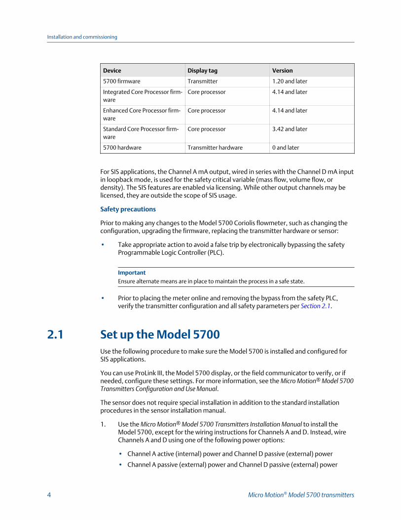
Device Display tag Version
5700 firmware Transmitter 1.20 and later
Integrated Core Processor firm-ware
Core processor 4.14 and later
Enhanced Core Processor firm-ware
Core processor 4.14 and later
Standard Core Processor firm-ware
Core processor 3.42 and later
5700 hardware Transmitter hardware 0 and later
For SIS applications, the Channel A mA output, wired in series with the Channel D mA inputin loopback mode, is used for the safety critical variable (mass flow, volume flow, ordensity). The SIS features are enabled via licensing. While other output channels may belicensed, they are outside the scope of SIS usage.
Safety precautions
Prior to making any changes to the Model 5700 Coriolis flowmeter, such as changing theconfiguration, upgrading the firmware, replacing the transmitter hardware or sensor:
• Take appropriate action to avoid a false trip by electronically bypassing the safetyProgrammable Logic Controller (PLC).
ImportantEnsure alternate means are in place to maintain the process in a safe state.
• Prior to placing the meter online and removing the bypass from the safety PLC,verify the transmitter configuration and all safety parameters per Section 2.1.
2.1 Set up the Model 5700Use the following procedure to make sure the Model 5700 is installed and configured forSIS applications.
You can use ProLink III, the Model 5700 display, or the field communicator to verify, or ifneeded, configure these settings. For more information, see the Micro Motion® Model 5700Transmitters Configuration and Use Manual.
The sensor does not require special installation in addition to the standard installationprocedures in the sensor installation manual.
1. Use the Micro Motion® Model 5700 Transmitters Installation Manual to install theModel 5700, except for the wiring instructions for Channels A and D. Instead, wireChannels A and D using one of the following power options:
• Channel A active (internal) power and Channel D passive (external) power
• Channel A passive (external) power and Channel D passive (external) power
Installation and commissioning
4 Micro Motion® Model 5700 transmitters
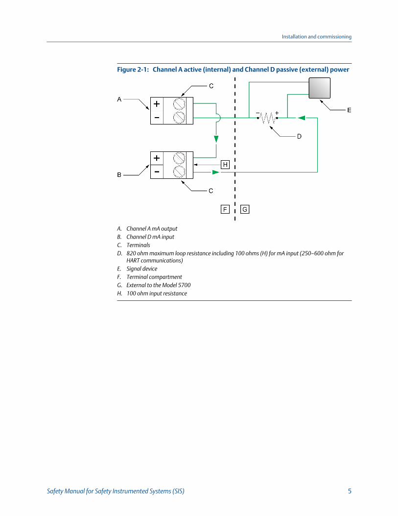
Channel A active (internal) and Channel D passive (external) powerFigure 2-1:
A. Channel A mA outputB. Channel D mA inputC. TerminalsD. 820 ohm maximum loop resistance including 100 ohms (H) for mA input (250–600 ohm for
HART communications)E. Signal deviceF. Terminal compartmentG. External to the Model 5700H. 100 ohm input resistance
Installation and commissioning
Safety Manual for Safety Instrumented Systems (SIS) 5
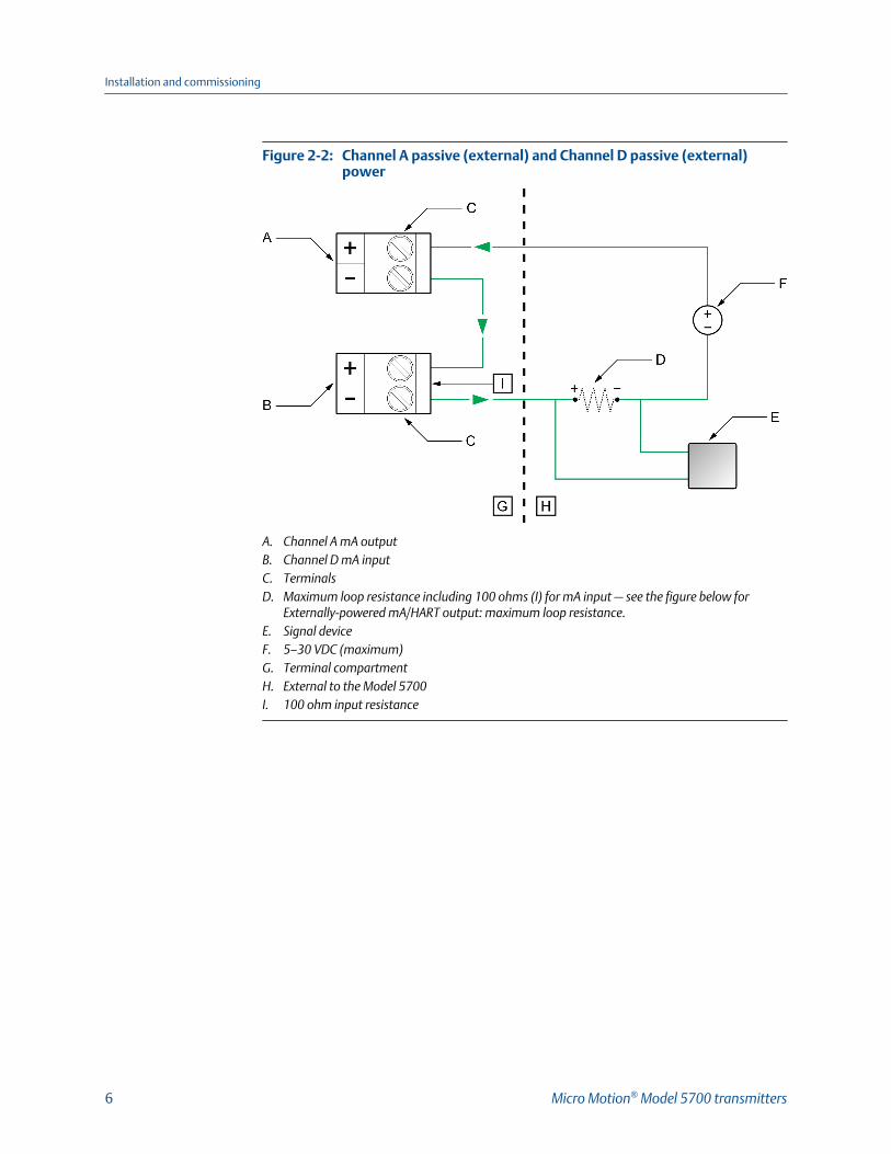
Channel A passive (external) and Channel D passive (external)power
Figure 2-2:
A. Channel A mA outputB. Channel D mA inputC. TerminalsD. Maximum loop resistance including 100 ohms (I) for mA input — see the figure below for
Externally-powered mA/HART output: maximum loop resistance.E. Signal deviceF. 5–30 VDC (maximum)G. Terminal compartmentH. External to the Model 5700I. 100 ohm input resistance
Installation and commissioning
6 Micro Motion® Model 5700 transmitters
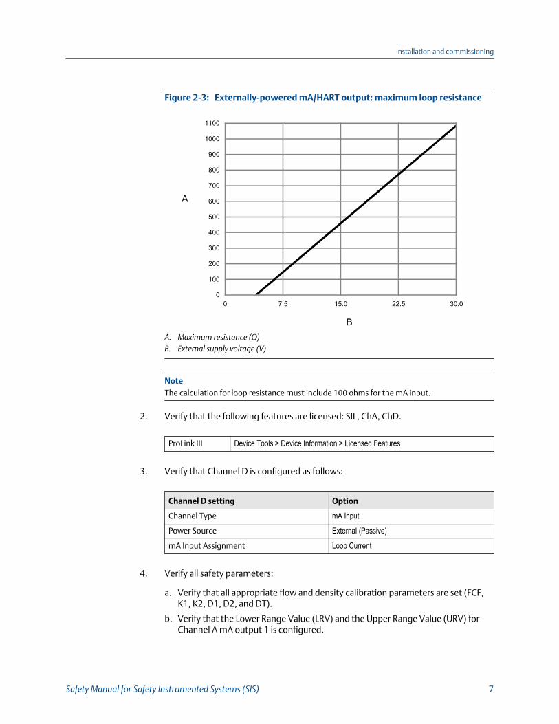
Externally-powered mA/HART output: maximum loop resistanceFigure 2-3:
0
100
200
300
400
500
600
700
800
900
1000
1100
0 7.5 15.0 22.5 30.0
B
A
A. Maximum resistance (Ω)B. External supply voltage (V)
NoteThe calculation for loop resistance must include 100 ohms for the mA input.
2. Verify that the following features are licensed: SIL, ChA, ChD.
ProLink III Device Tools > Device Information > Licensed Features
3. Verify that Channel D is configured as follows:
Channel D setting Option
Channel Type mA Input
Power Source External (Passive)
mA Input Assignment Loop Current
4. Verify all safety parameters:
a. Verify that all appropriate flow and density calibration parameters are set (FCF,K1, K2, D1, D2, and DT).
b. Verify that the Lower Range Value (LRV) and the Upper Range Value (URV) forChannel A mA output 1 is configured.
Installation and commissioning
Safety Manual for Safety Instrumented Systems (SIS) 7
c. Verify that the appropriate measurement units are configured (mass flow,volume flow, density, and temperature).
d. Verify that the HART Primary Variable (PV) is assigned to Channel A mA output.
e. Verify that the appropriate low flow cutoff parameter is configured.
f. Verify that the appropriate damping values are configured - such as flow,density, temperature, and added damping.
g. Verify that the mA Output Fault Action is set to Upscale or Downscale.
2.2 DiagnosticsThe SIL license enables a mA Output to mA Input comparison diagnostic.
If the difference between the programmed mA output and the actual mA input exceeds0.2 mA, an Electronics Failed alert becomes active and all analog outputs will beturned off (outputs all to zero) within 5 minutes. The alert shows up as:
On the display as: Verification of mAO1 Failed
On Prolink III as: mAO Verification Failed
After 5 minutes, the outputs are turned back on, and the mA output to mA inputcomparison check is performed again. If the alert was due to a transient condition, sincecleared, the transmitter will resume normal operations. If the alert was due to acomponent failure, the alert will remain active and the outputs will turn off again.
NoteThe mA output to mA input comparison diagnostic is disabled for the first 5 minutes after thetransmitter is powered up. This allows time to verify correct wiring and operation of the ChA-ChDmA output with mA input loopback.
2.3 Enable write-protection on the transmitterconfigurationWrite-protection helps protect the transmitter against accidental changes toconfiguration. When the transmitter is write-protected, no changes to the transmitterconfiguration will be accepted. You can perform all other functions, and you can view thetransmitter configuration parameters.
TipWrite-protecting the transmitter prevents accidental changes to configuration. It does not preventnormal operational use. You can always disable write-protection, perform any required configurationchanges, then re-enable write-protection.
There are two ways to enable write-protection:
Installation and commissioning
8 Micro Motion® Model 5700 transmitters
• A hardware switch on the transmitter display
• A software switch
The hardware switch takes precedence, as follows:
• If the hardware switch is ON, write-protection is always enabled.
• If the hardware switch is OFF, write-protection is controlled by the software switch.
You can enable write-protection using either the hardware switch or the software switch,or both.
• To enable write-protection using the hardware switch:
1. If you are in a hazardous area, power down the transmitter.
NoteNever remove the transmitter housing cover in a hazardous area when the transmitter ispowered up. Failure to follow these instructions may result in an explosion.
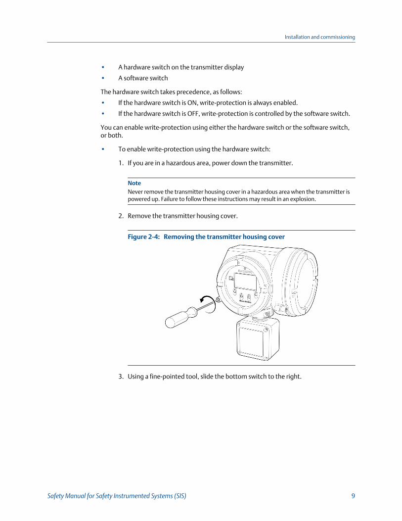
2. Remove the transmitter housing cover.
Removing the transmitter housing coverFigure 2-4:
3. Using a fine-pointed tool, slide the bottom switch to the right.
Installation and commissioning
Safety Manual for Safety Instrumented Systems (SIS) 9
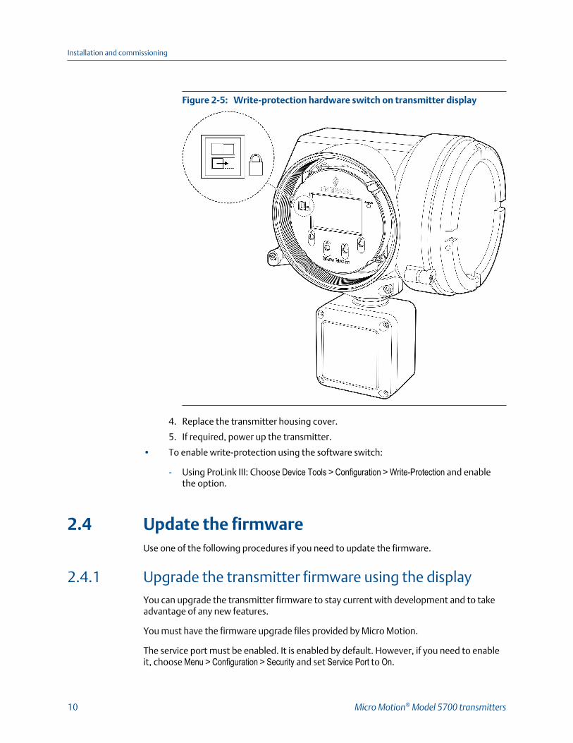
Write-protection hardware switch on transmitter displayFigure 2-5:
4. Replace the transmitter housing cover.
5. If required, power up the transmitter.
• To enable write-protection using the software switch:
- Using ProLink III: Choose Device Tools > Configuration > Write-Protection and enablethe option.
2.4 Update the firmwareUse one of the following procedures if you need to update the firmware.
2.4.1 Upgrade the transmitter firmware using the displayYou can upgrade the transmitter firmware to stay current with development and to takeadvantage of any new features.
You must have the firmware upgrade files provided by Micro Motion.
The service port must be enabled. It is enabled by default. However, if you need to enableit, choose Menu > Configuration > Security and set Service Port to On.
Installation and commissioning
10 Micro Motion® Model 5700 transmitters
1. Copy the folder containing the firmware upgrade files to a USB drive.
2. Open the wiring compartment and insert the USB drive into the service port.
CAUTION!
If the transmitter is in a hazardous area, do not open the wiring compartment. ContactMicro Motion for assistance.
3. Choose Menu > USB Options > USB Drive --> Transmitter > Update Device Software.
4. Select the firmware upgrade folder and follow the prompts.
NoteIf required, the transmitter upgrade procedure automatically includes an upgrade to the coreprocessor software.
If you chose to reboot the transmitter at a later date, you can reboot it from themenu, or you can power-cycle it.
5. Verify the transmitter configuration and all safety parameters.
See the verification steps in Section 2.1.
6. Enable write-protection.
See Section 2.3.
2.4.2 Upgrade the transmitter firmware using ProLink IIIYou can upgrade the transmitter firmware to stay current with development and to takeadvantage of any new features.
You must have the firmware upgrade files provided by Micro Motion.
1. Choose Device Tools > Transmitter Software Update.
2. Navigate to the folder containing the firmware upgrade files.
3. Click Update.
NoteIf required, the transmitter upgrade procedure automatically includes an upgrade to the coreprocessor software.
If you chose to reboot the transmitter at a later date, you can reboot it from thedisplay, or you can power-cycle it.
4. Verify the transmitter configuration and all safety parameters.
See the verification steps in Section 2.1.
5. Enable write-protection.
Installation and commissioning
Safety Manual for Safety Instrumented Systems (SIS) 11
See Section 2.3.
2.5 Replace equipmentIf you need to replace hardware, purchase all spare parts from Micro Motion.
You cannot use user-supplied components on any Micro Motion printed circuit assemblies.
1. Replace the hardware.
Use the appropriate sensor installation document or the Micro Motion® Model 5700Transmitters Installation Manual.
2. Verify the transmitter configuration and all safety parameters.
See the verification steps in Section 2.1.
3. Enable write-protection.
See Section 2.3.
Installation and commissioning
12 Micro Motion® Model 5700 transmitters
3 Proof testsTopics covered in this chapter:
• Proof test options
• Proof test 1
• Proof test 2
• Proof test 3
Proof tests detect transmitter failures that are not detected by transmitter diagnostics —mainly undetected failures that prevent the Safety Instrumented Function fromperforming correctly.
The frequency of proof testing, or the proof test interval, is determined by reliabilitycalculations for your transmitter model's Safety Instrumented Functions.
The proof tests must be performed at least as frequently as specified in the calculation tomaintain the required Safety Instrumented Function integrity.
3.1 Proof test optionsThe Coriolis flowmeter with a Model 5700 transmitter has 3 proof tests you can use todetect failures.
Proof tests can be performed using the display, Prolink III, or the field communicator.
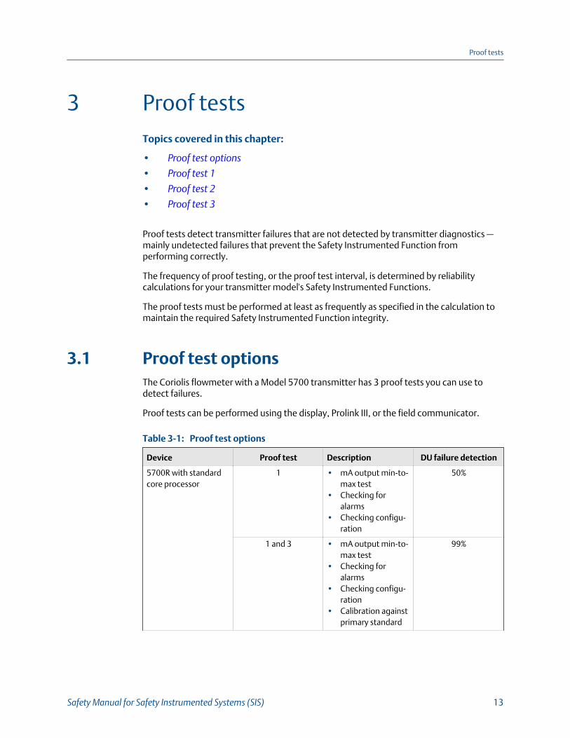
Proof test optionsTable 3-1:
Device Proof test Description DU failure detection
5700R with standardcore processor
1 • mA output min-to-max test
• Checking foralarms
• Checking configu-ration
50%
1 and 3 • mA output min-to-max test
• Checking foralarms
• Checking configu-ration
• Calibration againstprimary standard
99%
Proof tests
Safety Manual for Safety Instrumented Systems (SIS) 13
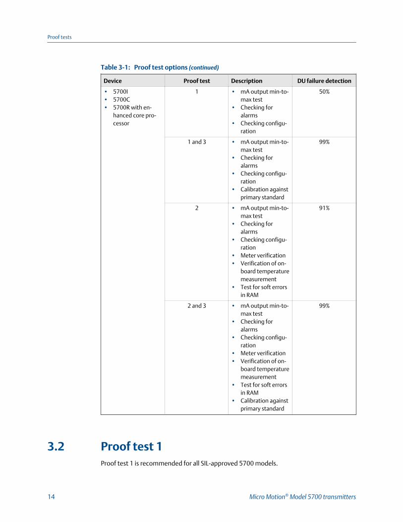
Proof test options (continued)Table 3-1:
Device Proof test Description DU failure detection
• 5700I• 5700C• 5700R with en-
hanced core pro-cessor
1 • mA output min-to-max test
• Checking foralarms
• Checking configu-ration
50%
1 and 3 • mA output min-to-max test
• Checking foralarms
• Checking configu-ration
• Calibration againstprimary standard
99%
2 • mA output min-to-max test
• Checking foralarms
• Checking configu-ration
• Meter verification• Verification of on-
board temperaturemeasurement
• Test for soft errorsin RAM
91%
2 and 3 • mA output min-to-max test
• Checking foralarms
• Checking configu-ration
• Meter verification• Verification of on-
board temperaturemeasurement
• Test for soft errorsin RAM
• Calibration againstprimary standard
99%
3.2 Proof test 1Proof test 1 is recommended for all SIL-approved 5700 models.
Proof tests
14 Micro Motion® Model 5700 transmitters
This procedure assumes that you are familiar with plant procedures. For details on how todo any of the following steps, see the Micro Motion® Model 5700 Transmitters with AnalogOutputs Configuration and Use Manual.
1. Take appropriate action to avoid a false trip by electronically bypassing the safetyProgrammable Logic Controller (PLC).
ImportantEnsure alternate means are in place to maintain the process in a safe state.
Example: Use Management of Change procedures to override the safety PLCfunction.
2. Disable write-protection.
If you need more information, you can modify the enable write-protectionprocedure. See Section 2.3.
3. Using an external device such as a fluke meter, test the mA output by setting eachmA output to the Fault Level specified for Upscale. Verify that the mA currentreaches that value, or use the default value (22mA).
This step tests for compliance voltage problems, such as low voltage on the looppower supply, or increased wiring resistance.
4. Using an external device such as a fluke meter, test the mA output by setting eachmA output to the Fault Level specified for Downscale. Verify that the mA currentreaches that value, or use the default value (2.0 mA).
This step tests for possible failures related to quiescent current.
5. Verify that the transmitter does not display alarms or warnings.
6. Verify all safety-critical configuration parameters.
See Step 4 in Section 2.1.
7. Restore the loop to full operation.
8. Enable write-protection.
See Section 2.3.
9. Remove the bypass from the safety PLC, or otherwise restore normal operation.
10. Document the results of this proof test as part of your plant safety managementprocedures.
3.3 Proof test 2Proof test 2 is recommended for an SIL-approved Model 5700 with the integrated coreprocessor (5700I / 5700C) or the enhanced core processor (5700R).
This procedure assumes that you are familiar with plant procedures. For details on how todo any of the following steps, see the Micro Motion® Model 5700 Transmitters with AnalogOutputs Configuration and Use Manual.
Proof tests
Safety Manual for Safety Instrumented Systems (SIS) 15
1. Take appropriate action to avoid a false trip by electronically bypassing the safetyProgrammable Logic Controller (PLC).
ImportantEnsure alternate means are in place to maintain the process in a safe state.
Example: Use Management of Change procedures to override the safety PLCfunction.
2. Disable write-protection.
If you need more information, you can modify the enable write-protectionprocedure. See Section 2.3.
3. Using an external device such as a fluke meter, test the mA output by setting eachmA output to the Fault Level specified for Upscale. Verify that the mA currentreaches that value, or use the default value (22mA).
This step tests for compliance voltage problems, such as low voltage on the looppower supply, or increased wiring resistance.
4. Using an external device such as a fluke meter, test the mA output by setting eachmA output to the Fault Level specified for Downscale. Verify that the mA currentreaches that value, or use the default value (2.0 mA).
This step tests for possible failures related to quiescent current.
5. Read the sensor temperature value. Compare it to the process temperature, andverify that this is a reasonable reading.
6. Power cycle the transmitter. Wait approximately 30 seconds for the flowmeter toreturn to normal operation.
7. Run a meter verification test.
8. Verify that the transmitter does not display alarms or warnings.
9. Verify all safety-critical configuration parameters.
See Step 4 in Section 2.1.
10. Restore the loop to full operation.
11. Enable write-protection.
See Section 2.3.
12. Remove the bypass from the safety PLC, or otherwise restore normal operation.
13. Document the results of this proof test as part of your plant safety managementprocedures.
3.4 Proof test 3Proof test 3 is recommended for all SIL-approved 5700 models.
Perform a full calibration against a primary standard.
Proof tests
16 Micro Motion® Model 5700 transmitters
NoteThe meter verification procedure and the onboard temperature verification tests are incorporatedinto a full calibration.
Proof tests
Safety Manual for Safety Instrumented Systems (SIS) 17

Proof tests
18 Micro Motion® Model 5700 transmitters
4 Operating constraintsTopics covered in this chapter:
• Reliability data
• Report failures
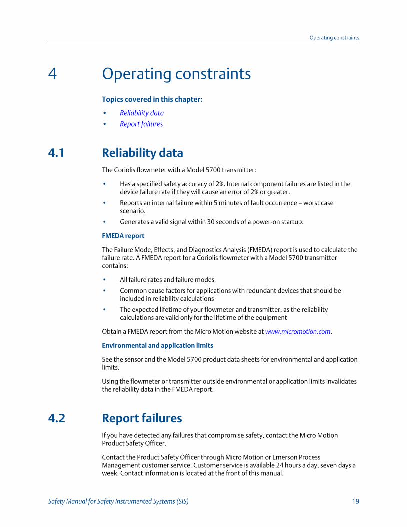
4.1 Reliability dataThe Coriolis flowmeter with a Model 5700 transmitter:
• Has a specified safety accuracy of 2%. Internal component failures are listed in thedevice failure rate if they will cause an error of 2% or greater.
• Reports an internal failure within 5 minutes of fault occurrence – worst casescenario.
• Generates a valid signal within 30 seconds of a power-on startup.
FMEDA report
The Failure Mode, Effects, and Diagnostics Analysis (FMEDA) report is used to calculate thefailure rate. A FMEDA report for a Coriolis flowmeter with a Model 5700 transmittercontains:
• All failure rates and failure modes
• Common cause factors for applications with redundant devices that should beincluded in reliability calculations
• The expected lifetime of your flowmeter and transmitter, as the reliabilitycalculations are valid only for the lifetime of the equipment
Obtain a FMEDA report from the Micro Motion website at www.micromotion.com.
Environmental and application limits
See the sensor and the Model 5700 product data sheets for environmental and applicationlimits.
Using the flowmeter or transmitter outside environmental or application limits invalidatesthe reliability data in the FMEDA report.
4.2 Report failuresIf you have detected any failures that compromise safety, contact the Micro MotionProduct Safety Officer.
Contact the Product Safety Officer through Micro Motion or Emerson ProcessManagement customer service. Customer service is available 24 hours a day, seven days aweek. Contact information is located at the front of this manual.
Operating constraints
Safety Manual for Safety Instrumented Systems (SIS) 19

Operating constraints
20 Micro Motion® Model 5700 transmitters

Operating constraints
Safety Manual for Safety Instrumented Systems (SIS) 21
*MMI-20029788*MMI-20029788
Rev AB
2015
Micro Motion Inc. USAWorldwide Headquarters7070 Winchester CircleBoulder, Colorado 80301T +1 303-527-5200T +1 800-522-6277F +1 303-530-8459www.micromotion.com
Micro Motion EuropeEmerson Process ManagementNeonstraat 16718 WX EdeThe NetherlandsT +31 (0) 70 413 6666F +31 (0) 318 495 556www.micromotion.nl
Micro Motion AsiaEmerson Process Management1 Pandan CrescentSingapore 128461Republic of SingaporeT +65 6777-8211F +65 6770-8003
Micro Motion United KingdomEmerson Process Management LimitedHorsfield WayBredbury Industrial EstateStockport SK6 2SU U.K.T +44 0870 240 1978F +44 0800 966 181
Micro Motion JapanEmerson Process Management1-2-5, Higashi ShinagawaShinagawa-kuTokyo 140-0002 JapanT +81 3 5769-6803F +81 3 5769-6844
©2015 Micro Motion, Inc. All rights reserved.
The Emerson logo is a trademark and service mark of EmersonElectric Co. Micro Motion, ELITE, ProLink, MVD and MVD DirectConnect marks are marks of one of the Emerson ProcessManagement family of companies. All other marks are property oftheir respective owners.