Embed Size (px)
Citation preview
American Journal of Engineering Research (AJER) 2014
w w w . a j e r . o r g
Page 139
American Journal of Engineering Research (AJER)
e-ISSN : 2320-0847 p-ISSN : 2320-0936
Volume-03, Issue-05, pp-139-150
www.ajer.org
Research Paper Open Access
Mobile Cell Selection In 4G Long Term Evolution-Advanced
(LTE-A) Networks
Murtadha Ali Nsaif Shukur1, Kuldip Pahwa
2, H. P. Sinha
3
1Master of Technology Final Year Student,2Professor and Head Of Department, 3Professor& Associate Director
1 2 3 Department of Electronics and Communication Engineering, Maharishi Markandeshwar University,
Mullana, Ambala, Haryana, INDIA
Abstract: - With the high demands for broadband mobile wireless communications and the emergence of new wireless multimedia applications constitute the motivation to the development of broadband wireless access
technologies in recent years. The Long Term Evolution/System Architecture Evolution (LTE/SAE) system has
been specified by the Third Generation Partnership Project (3GPP) on the way towards fourth-generation (4G)
mobile to ensure 3GPP keeping the dominance of the cellular communication technologies. Through the design
and optimization of new radio access techniques and a further evolution of the LTE-A systems, Cell selection is
the process of determining the cell(s) that provide service to each mobile station. By study the potential benefits
of global cell selection versus the current local mobile SNR-based decision protocol. In particular, and present
the new possibility available in OFDMA & SC-FDMA based systems, such as IEEE 802.16m and LTE-Advanced, of satisfying the minimal demand of a mobile station simultaneously by more than one base station.
After formalized the problems as an optimization problem; it's present how the mobile unit establishes this
connection with the strongest cell station in vicinity. To do this, the mobile unit has to overcome the challenges
of estimating the channel to communicate with the cell site and frequency synchronization. Also, multiple
mobile units communicate to the same receiver and from various distances. Hence, it is up to the mobile to
synchronize itself appropriately to the base stations. LTE-A uses two signals, the Primary Synchronization
Signal and the Secondary Synchronization Signal sequentially to determine which of the available cell sites, a
mobile would lock in to it. While inter-cell interference (ICI) one of problems for the downlink and uplink of
multi-cell systems (in general) and OFDMA& SC-FDMA networks (in particular).
Keywords: - LTE, LTE-A, OFDMA, SC-FDMA, cell searching and cell selection..
I. INTRODUCTION Long Term Evolution (LTE) is the result of the standardization work done by the 3GPP to achieve a
new high speed radio access in the mobile communications frame. 3GPP is a collaboration of groups of telecom
associations working on Global System for Mobile Communication (GSM) [1]. 3GPP published and introduced
the various standards for IP based system in Release 8, which is termed Long Term Evolution and abbreviated as LTE. Initially, LTE was introduced in the Release 8 in 2008. In 2010, the Release 9 was introduced to
provide enhancements to LTE and in 2011, its Release 10 was brought as LTE-Advanced, to expand the limits
and features of Release 8 and to meet the requirements of the International Mobile Telecommunications-
Advanced (IMT-Advanced) of ITU-R for the fourth generation (4G) of mobile technologies, and the future
operator and end user‘s requirements. The key reason of the evident of the LTE-A is the growing demand for
network services, such as VoIP, web browsing, video telephony, and video streaming, with constraints on delays
and bandwidth requirements, poses new challenges in the design of the future generation cellular networks.
Recently in 2011, LTE is further developed through Release 10 to satisfy ITU‘s IMT-Advanced requirements
for 4G cellular systems. LTE radio transmission and reception specifications are documented in TS 36.101 for
the user equipment (UE) and TS 36.104 for the eNB (Evolved Node B). As per these specifications, LTE is
theoretically capable of supporting up to 1Giga Bits per second (1Gbps) for fixed user and up to 100 Mega Bits
per second (100 Mbps) for high speed user. This is considerably high speed. For this reason, both research and
American Journal of Engineering Research (AJER) 2014
w w w . a j e r . o r g
Page 140
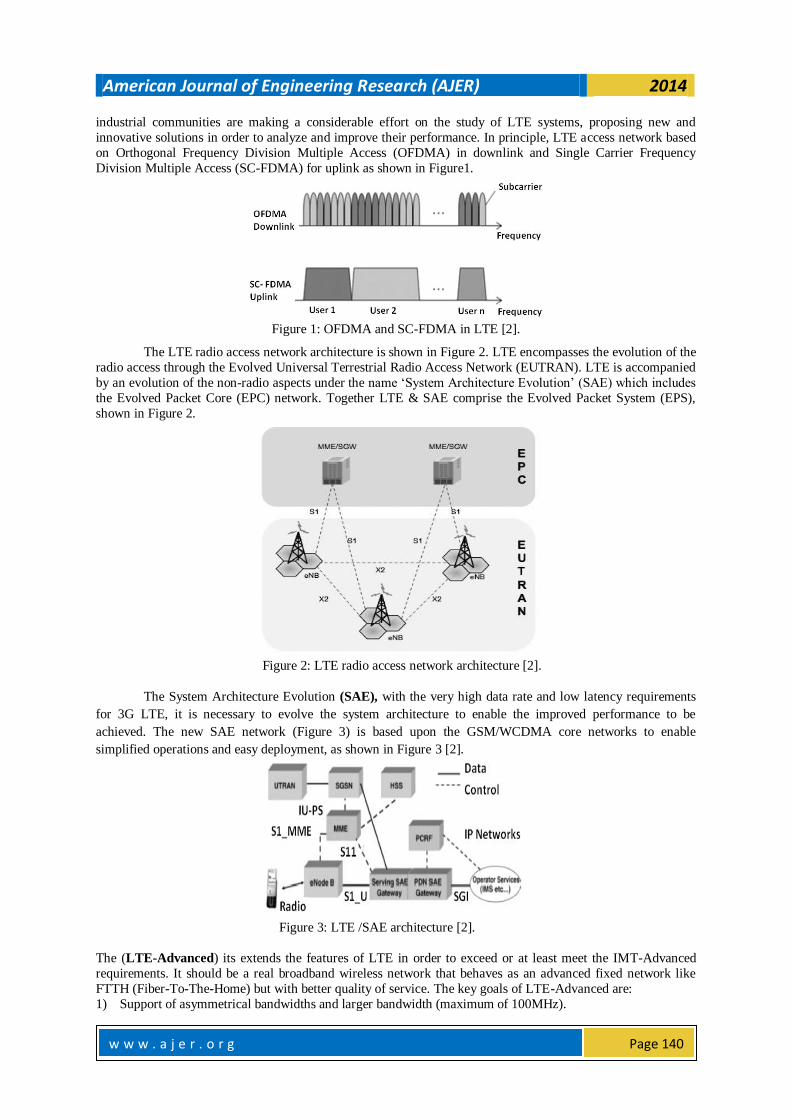
industrial communities are making a considerable effort on the study of LTE systems, proposing new and
innovative solutions in order to analyze and improve their performance. In principle, LTE access network based
on Orthogonal Frequency Division Multiple Access (OFDMA) in downlink and Single Carrier Frequency
Division Multiple Access (SC-FDMA) for uplink as shown in Figure1.
Figure 1: OFDMA and SC-FDMA in LTE [2].
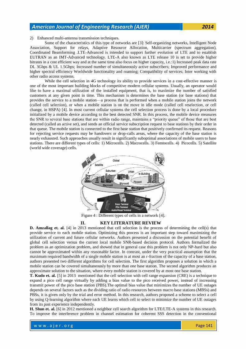
The LTE radio access network architecture is shown in Figure 2. LTE encompasses the evolution of the
radio access through the Evolved Universal Terrestrial Radio Access Network (EUTRAN). LTE is accompanied
by an evolution of the non-radio aspects under the name ‗System Architecture Evolution‘ (SAE) which includes
the Evolved Packet Core (EPC) network. Together LTE & SAE comprise the Evolved Packet System (EPS),
shown in Figure 2.
Figure 2: LTE radio access network architecture [2].
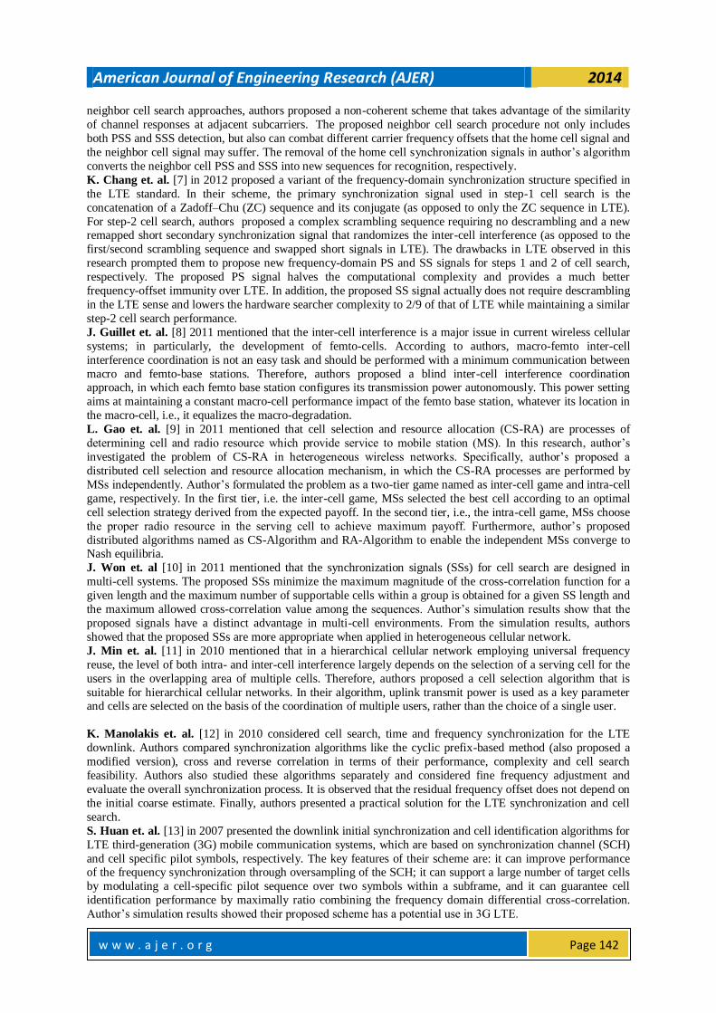
The System Architecture Evolution (SAE), with the very high data rate and low latency requirements
for 3G LTE, it is necessary to evolve the system architecture to enable the improved performance to be
achieved. The new SAE network (Figure 3) is based upon the GSM/WCDMA core networks to enable
simplified operations and easy deployment, as shown in Figure 3 [2].
Figure 3: LTE /SAE architecture [2].
The (LTE-Advanced) its extends the features of LTE in order to exceed or at least meet the IMT-Advanced
requirements. It should be a real broadband wireless network that behaves as an advanced fixed network like
FTTH (Fiber-To-The-Home) but with better quality of service. The key goals of LTE-Advanced are:
1) Support of asymmetrical bandwidths and larger bandwidth (maximum of 100MHz).
American Journal of Engineering Research (AJER) 2014
w w w . a j e r . o r g
Page 141
2) Enhanced multi-antenna transmission techniques.
Some of the characteristics of this type of networks are [3]: Self-organizing networks, Intelligent Node
Association, Support for relays, Adaptive Resource Allocation, Multicarrier (spectrum aggregation),
Coordinated Beamforming .LTE-Advanced is intended to support further evolution of LTE and to establish
EUTRAN as an IMT-Advanced technology. LTE-A also known as LTE release 10 is set to provide higher
bitrates in a cost efficient way and at the same time also focus on higher capacity, i.e.:1) Increased peak data rate
DL 3Gbps & UL 1.5Gbps; Increased number of simultaneously active subscribers; Improved performance and
higher spectral efficiency Worldwide functionality and roaming; Compatibility of services; Inter working with
other radio access systems. While the cell selection in 4G technology its ability to provide services in a cost-effective manner is
one of the most important building blocks of competitive modern cellular systems. Usually, an operator would
like to have a maximal utilization of the installed equipment, that is, to maximize the number of satisfied
customers at any given point in time. This mechanism is determines the base station (or base stations) that
provides the service to a mobile station—a process that is performed when a mobile station joins the network
(called cell selection), or when a mobile station is on the move in idle mode (called cell reselection, or cell
change, in HSPA) [4]. In most current cellular systems the cell selection process is done by a local procedure
initialized by a mobile device according to the best detected SNR. In this process, the mobile device measures
the SNR to several base stations that are within radio range, maintains a ―priority queue‖ of those that are best
detected (called an active set), and sends an official service subscription request to base stations by their order in
that queue. The mobile station is connected to the first base station that positively confirmed its request. Reasons for rejecting service requests may be handovers or drop-calls areas, where the capacity of the base station is
nearly exhausted. Such approaches usually result in significantly suboptimal associations of mobile users to base
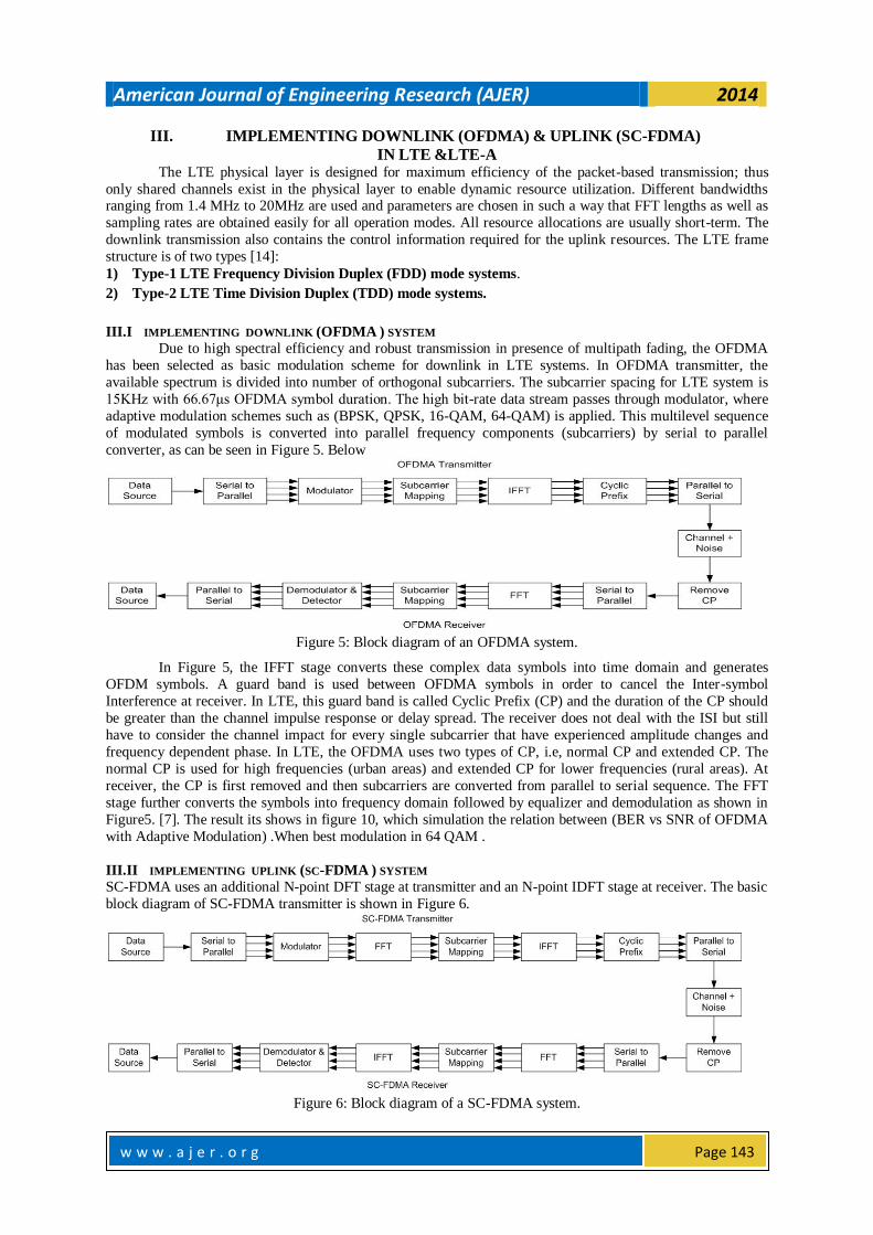
stations. There are different types of cells: 1) Microcells. 2) Macrocells. 3) Femtocells. 4) Picocells. 5) Satellite
(world wide coverage) cells.
Figure 4 : Different types of cells in a network [4].
II. KEY LITERATURE REVIEW D. Amzallag et. al. [4] in 2013 mentioned that cell selection is the process of determining the cell(s) that
provide service to each mobile station. Optimizing this process is an important step toward maximizing the
utilization of current and future cellular networks. Authors presented a discussion on the potential benefit of
global cell selection versus the current local mobile SNR-based decision protocol. Authors formalized the
problem as an optimization problem, and showed that in general case this problem is not only NP-hard but also
cannot be approximated within any reasonable factor. In contrast, under the very practical assumption that the maximum required bandwidth of a single mobile station is at most an r-fraction of the capacity of a base station,
authors presented two different algorithms for cell selection. The first algorithm proposes a solution in which a
mobile station can be covered simultaneously by more than one base station. The second algorithm produces an
approximate solution to the situation, where every mobile station is covered by at most one base station.
T. Kudo et. al. [5] in 2013 mentioned that the cell selection with cell range expansion (CRE) is a technique to
expand a pico cell range virtually by adding a bias value to the pico received power, instead of increasing
transmit power of the pico base station (PBS).The optimal bias value that minimizes the number of UE outages
depends on several factors such as the dividing ratio of radio resources between macro base stations (MBSs) and
PBSs, it is given only by the trial and error method. In this research, authors proposed a scheme to select a cell
by using Q-learning algorithm where each UE learns which cell to select to minimize the number of UE outages
from its past experience independently. H. Shun et. al. [6] in 2012 mentioned a neighbor cell search algorithm for LTE/LTE-A systems in this research.
To improve the interference problem in channel estimation for coherent SSS detection in the conventional
American Journal of Engineering Research (AJER) 2014
w w w . a j e r . o r g
Page 142
neighbor cell search approaches, authors proposed a non-coherent scheme that takes advantage of the similarity
of channel responses at adjacent subcarriers. The proposed neighbor cell search procedure not only includes
both PSS and SSS detection, but also can combat different carrier frequency offsets that the home cell signal and
the neighbor cell signal may suffer. The removal of the home cell synchronization signals in author‘s algorithm
converts the neighbor cell PSS and SSS into new sequences for recognition, respectively.
K. Chang et. al. [7] in 2012 proposed a variant of the frequency-domain synchronization structure specified in
the LTE standard. In their scheme, the primary synchronization signal used in step-1 cell search is the
concatenation of a Zadoff–Chu (ZC) sequence and its conjugate (as opposed to only the ZC sequence in LTE).
For step-2 cell search, authors proposed a complex scrambling sequence requiring no descrambling and a new remapped short secondary synchronization signal that randomizes the inter-cell interference (as opposed to the
first/second scrambling sequence and swapped short signals in LTE). The drawbacks in LTE observed in this
research prompted them to propose new frequency-domain PS and SS signals for steps 1 and 2 of cell search,
respectively. The proposed PS signal halves the computational complexity and provides a much better
frequency-offset immunity over LTE. In addition, the proposed SS signal actually does not require descrambling
in the LTE sense and lowers the hardware searcher complexity to 2/9 of that of LTE while maintaining a similar
step-2 cell search performance.
J. Guillet et. al. [8] 2011 mentioned that the inter-cell interference is a major issue in current wireless cellular
systems; in particularly, the development of femto-cells. According to authors, macro-femto inter-cell
interference coordination is not an easy task and should be performed with a minimum communication between
macro and femto-base stations. Therefore, authors proposed a blind inter-cell interference coordination approach, in which each femto base station configures its transmission power autonomously. This power setting
aims at maintaining a constant macro-cell performance impact of the femto base station, whatever its location in
the macro-cell, i.e., it equalizes the macro-degradation.
L. Gao et. al. [9] in 2011 mentioned that cell selection and resource allocation (CS-RA) are processes of
determining cell and radio resource which provide service to mobile station (MS). In this research, author‘s
investigated the problem of CS-RA in heterogeneous wireless networks. Specifically, author‘s proposed a
distributed cell selection and resource allocation mechanism, in which the CS-RA processes are performed by
MSs independently. Author‘s formulated the problem as a two-tier game named as inter-cell game and intra-cell
game, respectively. In the first tier, i.e. the inter-cell game, MSs selected the best cell according to an optimal
cell selection strategy derived from the expected payoff. In the second tier, i.e., the intra-cell game, MSs choose
the proper radio resource in the serving cell to achieve maximum payoff. Furthermore, author‘s proposed
distributed algorithms named as CS-Algorithm and RA-Algorithm to enable the independent MSs converge to Nash equilibria.
J. Won et. al [10] in 2011 mentioned that the synchronization signals (SSs) for cell search are designed in
multi-cell systems. The proposed SSs minimize the maximum magnitude of the cross-correlation function for a
given length and the maximum number of supportable cells within a group is obtained for a given SS length and
the maximum allowed cross-correlation value among the sequences. Author‘s simulation results show that the
proposed signals have a distinct advantage in multi-cell environments. From the simulation results, authors
showed that the proposed SSs are more appropriate when applied in heterogeneous cellular network.
J. Min et. al. [11] in 2010 mentioned that in a hierarchical cellular network employing universal frequency
reuse, the level of both intra- and inter-cell interference largely depends on the selection of a serving cell for the
users in the overlapping area of multiple cells. Therefore, authors proposed a cell selection algorithm that is
suitable for hierarchical cellular networks. In their algorithm, uplink transmit power is used as a key parameter and cells are selected on the basis of the coordination of multiple users, rather than the choice of a single user.
K. Manolakis et. al. [12] in 2010 considered cell search, time and frequency synchronization for the LTE
downlink. Authors compared synchronization algorithms like the cyclic prefix-based method (also proposed a
modified version), cross and reverse correlation in terms of their performance, complexity and cell search
feasibility. Authors also studied these algorithms separately and considered fine frequency adjustment and
evaluate the overall synchronization process. It is observed that the residual frequency offset does not depend on
the initial coarse estimate. Finally, authors presented a practical solution for the LTE synchronization and cell
search.
S. Huan et. al. [13] in 2007 presented the downlink initial synchronization and cell identification algorithms for
LTE third-generation (3G) mobile communication systems, which are based on synchronization channel (SCH)
and cell specific pilot symbols, respectively. The key features of their scheme are: it can improve performance of the frequency synchronization through oversampling of the SCH; it can support a large number of target cells
by modulating a cell-specific pilot sequence over two symbols within a subframe, and it can guarantee cell
identification performance by maximally ratio combining the frequency domain differential cross-correlation.
Author‘s simulation results showed their proposed scheme has a potential use in 3G LTE.
American Journal of Engineering Research (AJER) 2014
w w w . a j e r . o r g
Page 143
III. IMPLEMENTING DOWNLINK (OFDMA) & UPLINK (SC-FDMA)
IN LTE <E-A The LTE physical layer is designed for maximum efficiency of the packet-based transmission; thus
only shared channels exist in the physical layer to enable dynamic resource utilization. Different bandwidths ranging from 1.4 MHz to 20MHz are used and parameters are chosen in such a way that FFT lengths as well as
sampling rates are obtained easily for all operation modes. All resource allocations are usually short-term. The
downlink transmission also contains the control information required for the uplink resources. The LTE frame
structure is of two types [14]:
1) Type-1 LTE Frequency Division Duplex (FDD) mode systems.
2) Type-2 LTE Time Division Duplex (TDD) mode systems.
III.I IMPLEMENTING DOWNLINK (OFDMA ) SYSTEM
Due to high spectral efficiency and robust transmission in presence of multipath fading, the OFDMA
has been selected as basic modulation scheme for downlink in LTE systems. In OFDMA transmitter, the
available spectrum is divided into number of orthogonal subcarriers. The subcarrier spacing for LTE system is
15KHz with 66.67μs OFDMA symbol duration. The high bit-rate data stream passes through modulator, where
adaptive modulation schemes such as (BPSK, QPSK, 16-QAM, 64-QAM) is applied. This multilevel sequence
of modulated symbols is converted into parallel frequency components (subcarriers) by serial to parallel
converter, as can be seen in Figure 5. Below
Figure 5: Block diagram of an OFDMA system.
In Figure 5, the IFFT stage converts these complex data symbols into time domain and generates
OFDM symbols. A guard band is used between OFDMA symbols in order to cancel the Inter-symbol
Interference at receiver. In LTE, this guard band is called Cyclic Prefix (CP) and the duration of the CP should
be greater than the channel impulse response or delay spread. The receiver does not deal with the ISI but still
have to consider the channel impact for every single subcarrier that have experienced amplitude changes and
frequency dependent phase. In LTE, the OFDMA uses two types of CP, i.e, normal CP and extended CP. The
normal CP is used for high frequencies (urban areas) and extended CP for lower frequencies (rural areas). At
receiver, the CP is first removed and then subcarriers are converted from parallel to serial sequence. The FFT
stage further converts the symbols into frequency domain followed by equalizer and demodulation as shown in
Figure5. [7]. The result its shows in figure 10, which simulation the relation between (BER vs SNR of OFDMA
with Adaptive Modulation) .When best modulation in 64 QAM .
III.II IMPLEMENTING UPLINK (SC-FDMA ) SYSTEM
SC-FDMA uses an additional N-point DFT stage at transmitter and an N-point IDFT stage at receiver. The basic
block diagram of SC-FDMA transmitter is shown in Figure 6.
Figure 6: Block diagram of a SC-FDMA system.
American Journal of Engineering Research (AJER) 2014
w w w . a j e r . o r g
Page 144
In SC-FDMA, the data is mapped into signal constellation according to the QPSK, 16-QAM, or 64-
QAM modulation, depending upon the channel conditions similarly as in OFDMA. Whereas, the QPSK/QAM
symbols do not directly modulate the subcarriers; these symbols passes through a serial to parallel converter
followed by a DFT block that produce discrete frequency domain representation of the QPSK/QAM symbols.
Pulse shaping is followed by DFT element, but it is optional and sometimes needs to shape the output signal
from DFT. If pulse shaping is active then in the actual signal, bandwidth extension occurs. The Discrete Fourier
symbols from the output of DFT block are then mapped with the subcarriers in subcarrier mapping block. After
mapping the frequency domain; the modulated subcarriers pass through IDFT for time domain conversion. The
rest of transmitter operation is similar as OFDMA. The result its shown in figure 11, which simulation by help Table1the output it will be the relation between (BER vs SNR of SC-FDMA with Adaptive Modulation) Best
modulation in 64 QAM .
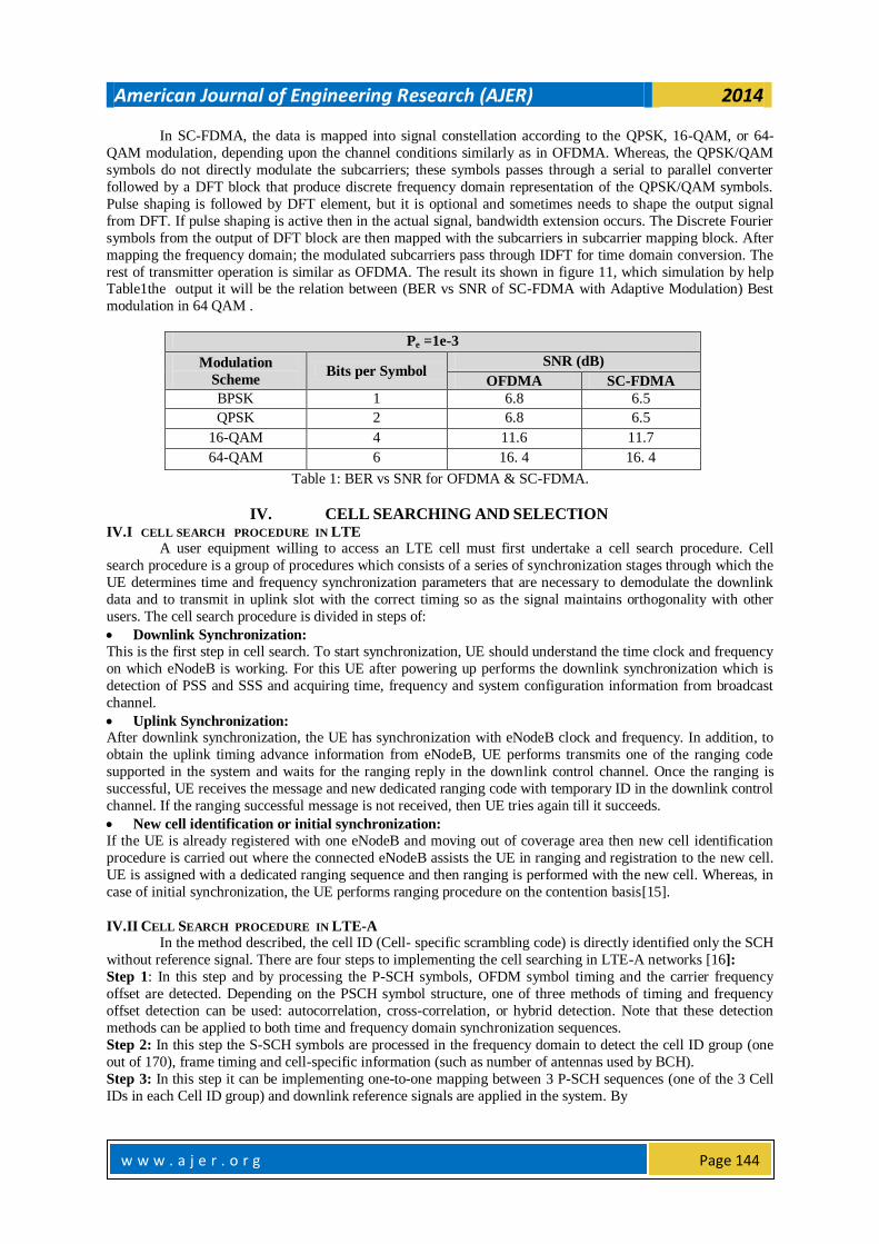
Pe =1e-3
Modulation
Scheme Bits per Symbol
SNR (dB)
OFDMA SC-FDMA
BPSK 1 6.8 6.5
QPSK 2 6.8 6.5
16-QAM 4 11.6 11.7
64-QAM 6 16. 4 16. 4
Table 1: BER vs SNR for OFDMA & SC-FDMA.
IV. CELL SEARCHING AND SELECTION IV.I CELL SEARCH PROCEDURE IN LTE
A user equipment willing to access an LTE cell must first undertake a cell search procedure. Cell
search procedure is a group of procedures which consists of a series of synchronization stages through which the
UE determines time and frequency synchronization parameters that are necessary to demodulate the downlink
data and to transmit in uplink slot with the correct timing so as the signal maintains orthogonality with other
users. The cell search procedure is divided in steps of:
Downlink Synchronization: This is the first step in cell search. To start synchronization, UE should understand the time clock and frequency
on which eNodeB is working. For this UE after powering up performs the downlink synchronization which is
detection of PSS and SSS and acquiring time, frequency and system configuration information from broadcast
channel.
Uplink Synchronization: After downlink synchronization, the UE has synchronization with eNodeB clock and frequency. In addition, to
obtain the uplink timing advance information from eNodeB, UE performs transmits one of the ranging code
supported in the system and waits for the ranging reply in the downlink control channel. Once the ranging is
successful, UE receives the message and new dedicated ranging code with temporary ID in the downlink control
channel. If the ranging successful message is not received, then UE tries again till it succeeds.
New cell identification or initial synchronization: If the UE is already registered with one eNodeB and moving out of coverage area then new cell identification
procedure is carried out where the connected eNodeB assists the UE in ranging and registration to the new cell.
UE is assigned with a dedicated ranging sequence and then ranging is performed with the new cell. Whereas, in
case of initial synchronization, the UE performs ranging procedure on the contention basis[15].
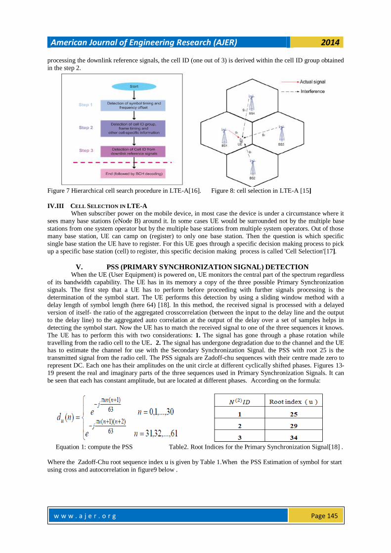
IV.II CELL SEARCH PROCEDURE IN LTE-A In the method described, the cell ID (Cell- specific scrambling code) is directly identified only the SCH
without reference signal. There are four steps to implementing the cell searching in LTE-A networks [16]:
Step 1: In this step and by processing the P-SCH symbols, OFDM symbol timing and the carrier frequency
offset are detected. Depending on the PSCH symbol structure, one of three methods of timing and frequency
offset detection can be used: autocorrelation, cross-correlation, or hybrid detection. Note that these detection
methods can be applied to both time and frequency domain synchronization sequences.
Step 2: In this step the S-SCH symbols are processed in the frequency domain to detect the cell ID group (one
out of 170), frame timing and cell-specific information (such as number of antennas used by BCH).
Step 3: In this step it can be implementing one-to-one mapping between 3 P-SCH sequences (one of the 3 Cell
IDs in each Cell ID group) and downlink reference signals are applied in the system. By
American Journal of Engineering Research (AJER) 2014
w w w . a j e r . o r g
Page 145
processing the downlink reference signals, the cell ID (one out of 3) is derived within the cell ID group obtained
in the step 2.
Figure 7 Hierarchical cell search procedure in LTE-A[16]. Figure 8: cell selection in LTE-A [15]
IV.III CELL SELECTION IN LTE-A When subscriber power on the mobile device, in most case the device is under a circumstance where it
sees many base stations (eNode B) around it. In some cases UE would be surrounded not by the multiple base
stations from one system operator but by the multiple base stations from multiple system operators. Out of those
many base station, UE can camp on (register) to only one base station. Then the question is which specific
single base station the UE have to register. For this UE goes through a specific decision making process to pick
up a specific base station (cell) to register, this specific decision making process is called 'Cell Selection'[17].
V. PSS (PRIMARY SYNCHRONIZATION SIGNAL) DETECTION When the UE (User Equipment) is powered on, UE monitors the central part of the spectrum regardless
of its bandwidth capability. The UE has in its memory a copy of the three possible Primary Synchronization
signals. The first step that a UE has to perform before proceeding with further signals processing is the
determination of the symbol start. The UE performs this detection by using a sliding window method with a
delay length of symbol length (here 64) [18]. In this method, the received signal is processed with a delayed
version of itself- the ratio of the aggregated crosscorrelation (between the input to the delay line and the output
to the delay line) to the aggregated auto correlation at the output of the delay over a set of samples helps in
detecting the symbol start. Now the UE has to match the received signal to one of the three sequences it knows.
The UE has to perform this with two considerations: 1. The signal has gone through a phase rotation while
travelling from the radio cell to the UE. 2. The signal has undergone degradation due to the channel and the UE has to estimate the channel for use with the Secondary Synchronization Signal. the PSS with root 25 is the
transmitted signal from the radio cell. The PSS signals are Zadoff-chu sequences with their centre made zero to
represent DC. Each one has their amplitudes on the unit circle at different cyclically shifted phases. Figures 13-
19 present the real and imaginary parts of the three sequences used in Primary Synchronization Signals. It can
be seen that each has constant amplitude, but are located at different phases. According on the formula:
Equation 1: compute the PSS Table2. Root Indices for the Primary Synchronization Signal[18] .
Where the Zadoff-Chu root sequence index u is given by Table 1.When the PSS Estimation of symbol for start
using cross and autocorrelation in figure9 below .
American Journal of Engineering Research (AJER) 2014
w w w . a j e r . o r g
Page 146
Figure 9. Estimation of symbol start using cross and autocorrelation [19]. Equation 2: compute the SSS
Figure 9 shows the representation of the actual and estimated channel. At the end of this step the UE knows:-
1. Symbol boundary. 2. Cell ID index(N(2)ID). 3. Sub frame timing describes that in FDD systems the PSS is
transmitted in subframe 0 or Subframe 5. So, with the detection of PSS, the UE knows it is synchronized with
either subframe 0 or subframe 5. Determination of whether it is subframe 0 or subframe 5 will enable frame
timing synchronization which will be performed with the detection of SSS. 4. Channel Estimate.
VI. SSS (SECONDARY SYNCHRONIZATION SIGNAL) DETECTION.
The sequence d(0),...,d(61) used for the secondary synchronization signal is an interleaved concatenation of two length-31 binary sequences. The concatenated sequence is scrambled with a scrambling
sequence given by the primary synchronization signal. The combination of two length-31 sequences defining the
secondary synchronization signal differs between subframe 0 and subframe 5 according to[18]: The above
equation clearly indicates that the SSS is different for subframe 0 and subframe 5. So, detection of SSS will
enable UE to determine the frame timing as well. The detection of SSS is a coherent process. Since the UE has
determined an estimate of the channel from the PSS, it now removes the effects of the channel before it detects
the SSS. The SSS and PSS are closely located in time to enable the coherent detection[20]. known to the UE and
can be descrambled from the received signal, So, has only one unknown m0 in s(m0)0(n). The result as shows in
figures ( 20, 21), which is represent the real and imaginary part, that each has constant amplitude, but are located
at different phases .
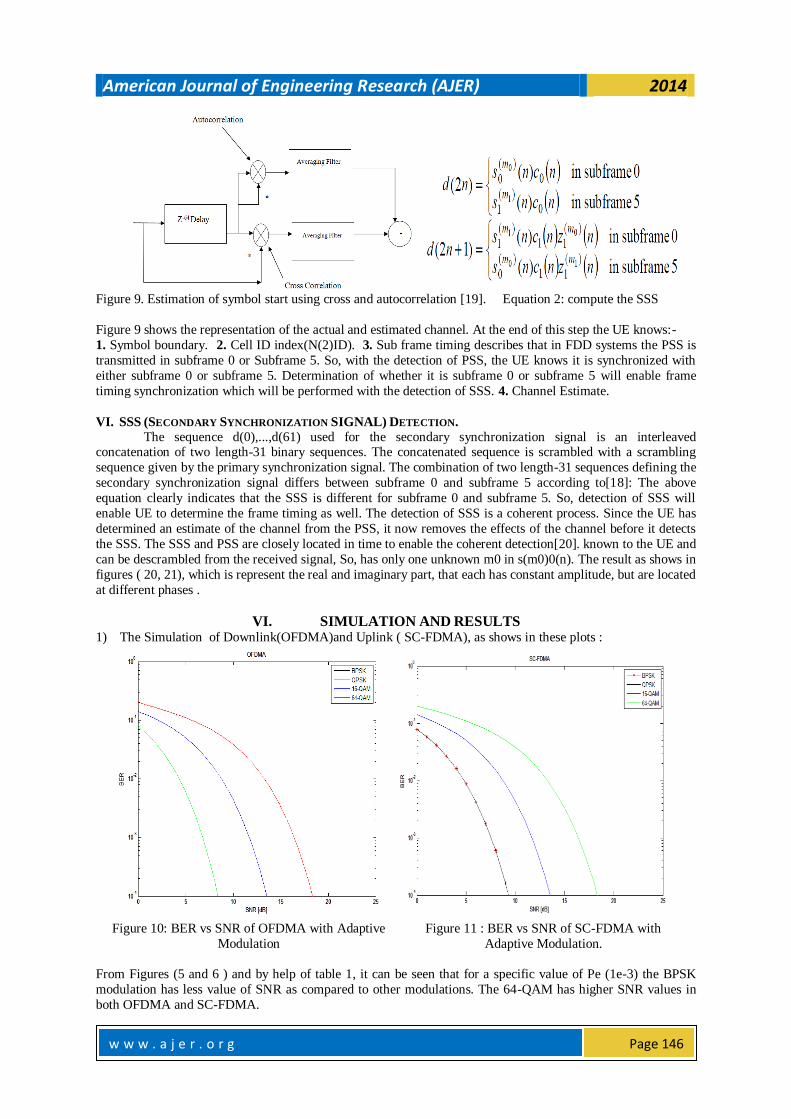
VI. SIMULATION AND RESULTS 1) The Simulation of Downlink(OFDMA)and Uplink ( SC-FDMA), as shows in these plots :
Figure 10: BER vs SNR of OFDMA with Adaptive
Modulation
Figure 11 : BER vs SNR of SC-FDMA with
Adaptive Modulation.
From Figures (5 and 6 ) and by help of table 1, it can be seen that for a specific value of Pe (1e-3) the BPSK
modulation has less value of SNR as compared to other modulations. The 64-QAM has higher SNR values in
both OFDMA and SC-FDMA.
American Journal of Engineering Research (AJER) 2014
w w w . a j e r . o r g
Page 147
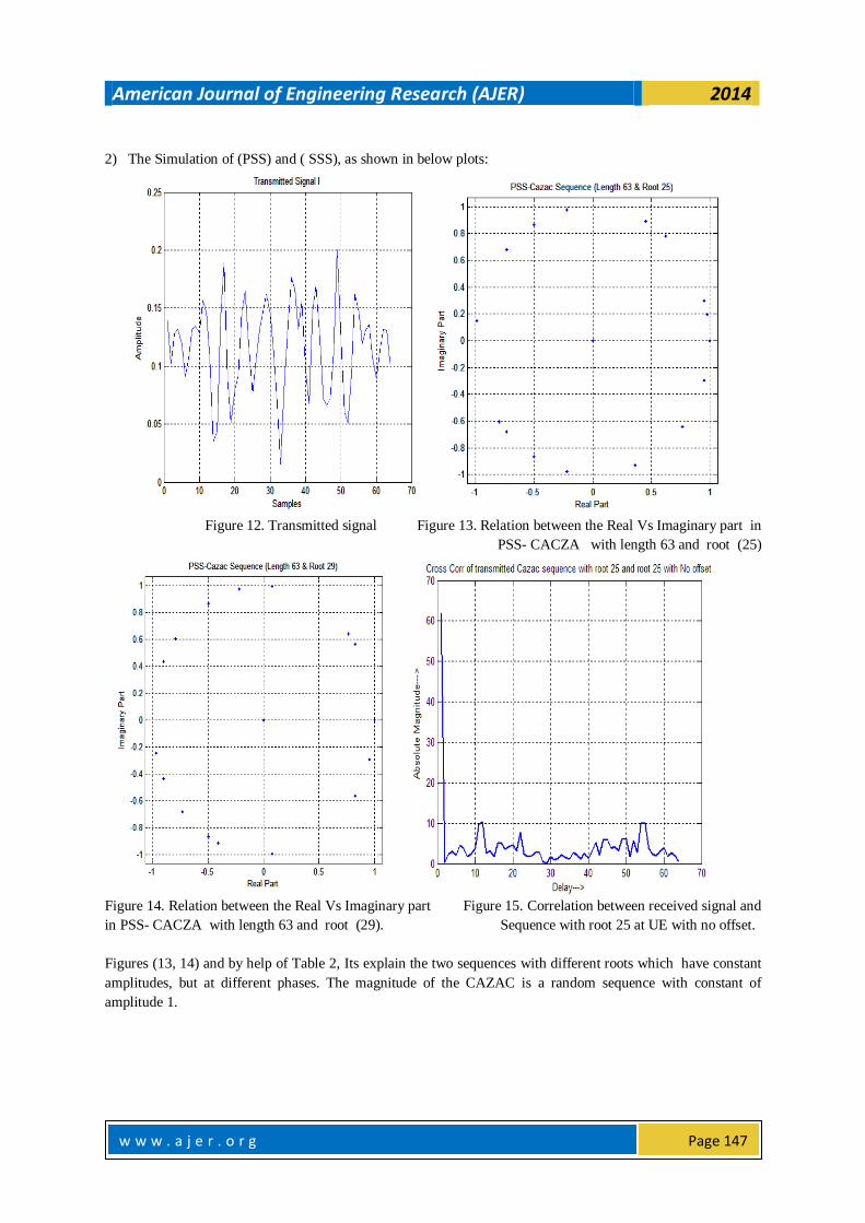
2) The Simulation of (PSS) and ( SSS), as shown in below plots:
Figure 12. Transmitted signal Figure 13. Relation between the Real Vs Imaginary part in
PSS- CACZA with length 63 and root (25)
Figure 14. Relation between the Real Vs Imaginary part Figure 15. Correlation between received signal and
in PSS- CACZA with length 63 and root (29). Sequence with root 25 at UE with no offset.
Figures (13, 14) and by help of Table 2, Its explain the two sequences with different roots which have constant
amplitudes, but at different phases. The magnitude of the CAZAC is a random sequence with constant of
amplitude 1.
American Journal of Engineering Research (AJER) 2014
w w w . a j e r . o r g
Page 148
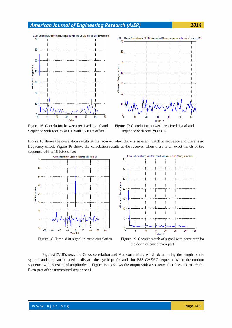
Figure 16. Correlation between received signal and Figure17: Correlation between received signal and
Sequence with root 25 at UE with 15 KHz offset. sequence with root 29 at UE
Figure 15 shows the correlation results at the receiver when there is an exact match in sequence and there is no
frequency offset. Figure 16 shows the correlation results at the receiver when there is an exact match of the
sequence with a 15 KHz offset
Figure 18. Time shift signal in Auto correlation Figure 19. Correct match of signal with correlator for
the de-interleaved even part
Figures(17,18)shows the Cross correlation and Autocorrelation, which determining the length of the
symbol and this can be used to discard the cyclic prefix and for PSS CAZAC sequence when the random
sequence with constant of amplitude 1. Figure 19 its shows the output with a sequence that does not match the
Even part of the transmitted sequence s1.
American Journal of Engineering Research (AJER) 2014
w w w . a j e r . o r g
Page 149
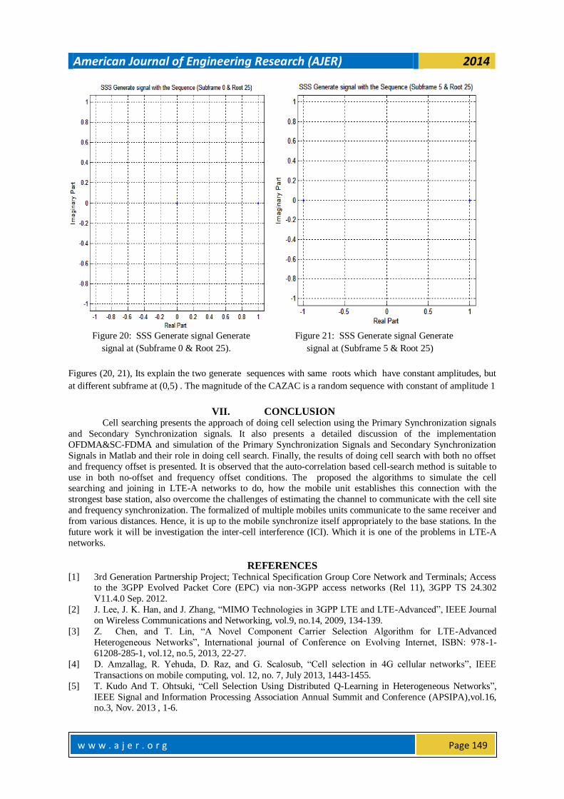
Figure 20: SSS Generate signal Generate Figure 21: SSS Generate signal Generate
signal at (Subframe 0 & Root 25). signal at (Subframe 5 & Root 25)
Figures (20, 21), Its explain the two generate sequences with same roots which have constant amplitudes, but
at different subframe at (0,5) . The magnitude of the CAZAC is a random sequence with constant of amplitude 1
VII. CONCLUSION Cell searching presents the approach of doing cell selection using the Primary Synchronization signals
and Secondary Synchronization signals. It also presents a detailed discussion of the implementation
OFDMA&SC-FDMA and simulation of the Primary Synchronization Signals and Secondary Synchronization
Signals in Matlab and their role in doing cell search. Finally, the results of doing cell search with both no offset
and frequency offset is presented. It is observed that the auto-correlation based cell-search method is suitable to
use in both no-offset and frequency offset conditions. The proposed the algorithms to simulate the cell searching and joining in LTE-A networks to do, how the mobile unit establishes this connection with the
strongest base station, also overcome the challenges of estimating the channel to communicate with the cell site
and frequency synchronization. The formalized of multiple mobiles units communicate to the same receiver and
from various distances. Hence, it is up to the mobile synchronize itself appropriately to the base stations. In the
future work it will be investigation the inter-cell interference (ICI). Which it is one of the problems in LTE-A
networks.
REFERENCES [1] 3rd Generation Partnership Project; Technical Specification Group Core Network and Terminals; Access
to the 3GPP Evolved Packet Core (EPC) via non-3GPP access networks (Rel 11), 3GPP TS 24.302
V11.4.0 Sep. 2012.
[2] J. Lee, J. K. Han, and J. Zhang, ―MIMO Technologies in 3GPP LTE and LTE-Advanced‖, IEEE Journal
on Wireless Communications and Networking, vol.9, no.14, 2009, 134-139.
[3] Z. Chen, and T. Lin, ―A Novel Component Carrier Selection Algorithm for LTE-Advanced
Heterogeneous Networks‖, International journal of Conference on Evolving Internet, ISBN: 978-1-
61208-285-1, vol.12, no.5, 2013, 22-27.
[4] D. Amzallag, R. Yehuda, D. Raz, and G. Scalosub, ―Cell selection in 4G cellular networks‖, IEEE
Transactions on mobile computing, vol. 12, no. 7, July 2013, 1443-1455.
[5] T. Kudo And T. Ohtsuki, ―Cell Selection Using Distributed Q-Learning in Heterogeneous Networks‖,
IEEE Signal and Information Processing Association Annual Summit and Conference (APSIPA),vol.16, no.3, Nov. 2013 , 1-6.
American Journal of Engineering Research (AJER) 2014
w w w . a j e r . o r g
Page 150
[6] H. Shun And F. Liu, ―A Non-coherent Neighbor Cell Search Scheme for LTE/LTE-A Systems‖,
International journal of electronic central, vol. 19, no.3, 2012, 88-93.
[7] K. Chang, P. Ho And Y. Choi, ―Signal Design for Reduced Complexity and Accurate Cell
Search/Synchronization in OFDM-Based Cellular Systems‖, IEEE Transactions on vehicular
technology, vol. 61, no. 9, Nov. 2012, 4170-4175.
[8] J. Guillet, L. Brunel And N. Gresset, ―Downlink Femto-Macro ICIC with Blind Long-Term Power
Setting‖, IEEE Personal Indoor and Mobile Radio Communications, vol.10, no.7, 2011, 277-283.
[9] L. Gao, X. Wang, G. Sun and Y. Xu, ―A game approach for cell selection and resource allocation in
heterogeneous wireless networks‖, Sensor mesh and ad hoc communications and networks, 2011 8th annual IEEE communications society conference, vol.8, no.5, June 2011, 530-538.
[10] J. Won, K. Kijun, J. Young Jin, S. Kwang And S. Kim, ―Synchronization Signal Design for Cell Search
in 3GPP LTE-A HCN‖, IEEE Signal Design and its Applications in Communications (IWSDA), 2011
Fifth International Workshop, ISBN 978-1-61284-047-5, vol.17, no.6, 2011, 150-153.
[11] J. Min, D. Hocho, "efficient cell selection algorithm in hierarchical cellular networks: multi-user
coordination", IEEE communications letters, vol. 14, no. 2, Feb. 2010, 466-472.
[12] K. Manolakis, V. Jungnickel, ―Synchronization and Cell Search for 3GPP LTE‖, International Journal of
electronics and computing, vol.15, no.6, 2010, 1-7.
[13] S. Huan, Z. Jian-hua, ―Cell search algorithms for the 3G long-term evolution‖, International Journal of
china universities of post and telecommunications, vol. 14, no. 2, June 2007, 673-680.
[14] 3rd Generation Partnership Project; Technical Specification Group Services and System Aspects; Service requirements for the Evolved Packet System (EPS) (Rel 12), 3GPP TS 22.278 V12.1.0 June 2012.
[15] A. Hassen, and T. Woldes, ―Synchronization in Cognitive Overlay Systems‖, International journal of
electrical engineer, vol.19, no.9, 2012, 112-130.
[16] K. Davaslioglu and E. Ayanoglu, ―Interference-based cell selection in 4G heterogenous networks‖,
Department of Electrical Engineering and Computer Science, IEEE wireless communications, vol. 11, no.
4, Feb. 2013, 13-25.
[17] C. Chang , C. Yuan Hsieh, and Y. Han Chen, ―A preference value-based cell selection scheme in
heterogeneous wireless network‖, This the direction of IEEE communications society subject matter
experts for publication in the wcnc, vol.7, no.4, 2012, 112-120.
[18] K. SoonKim, S. Woong Kim, Y. SooCho, And J. YoungAhn, ―Synchronization and Cell Search
Technique Using Preamble for SC-FDMA& OFDMA Cellular Systems‖, IEEE Transactions on
vehicular technology, vol. 10, no.5, 2007,1-16. [19] C. Sun, J. Jiang, G. Lu, ―Primary synchronization Channel Design for OFDM&SC-FDMA Based
Mobile Communication Systems‖, IEEE International Conference on Cybernetics and Informatics in
Electrical Engineering, vol. 163, 2013, 1623-1630.
[20] D. Liao, D. Qiu, and A. Elhakeem, ―Coding based Synchronization Algorithm for Secondary
Synchronization Channel in LTE‖, Communication Software and Networks, International Conference on
01/2009, ISBN: 978-0-7695-3522-7, vol.3, 2009, 776-784.
Murtadha Ali Nsaif Shukur is a student Final year M.Tech (Electronics and Communication Engineering) at MM University, Mullana, Ambala, Haryana, INDIA. He has received his B.Tech (Communication Engineering) from Technical Collage of Al- Najaf, and Diploma in (Electrical
branch) from Technical Institute of Al-Najaf, Iraq.