Embed Size (px)
Citation preview
8/7/2019 Mobile Picture
http://slidepdf.com/reader/full/mobile-picture 1/17
1
Mobile Communication
Services and Systems
Lecture [1]
Basics of Mobile Communication
Mohammed Elmusrati University of Vaasa
References• This course consists of 12 lecture.
• We will use different books and articles for the course materials.
• The main two books are:
– J. Eberspächer, H. Vögel, and C. Bettstetter, GSM, Switching, Services, and Protocols 2nd ed, Wiley (ISBN 0471 49903 X)
– H. Holma and A. Toskala, WCDMA for UMTS 3ed, Wiley (ISBN 0-470-
87096-6)
• Other used material
– J. Korhonen, Introduction to 3G Mobile Communication 2nd ed, ISBN 1-58053-507-0
– A. Mishra, Fundamentals of Cellular Network Planning and Optimization ,Wiley (ISBN 0-470-86267-X)
– R. Steele and L. Hanzo, Mobile radio Communications 2nd ed., Wiley (ISBN0-471-97806-X)
– Understanding Telecommunications parts 1 and 2, (ISBN 91-44-00212-2)
– C. Politis ,Cooperative Networks for the Future Wireless World , IEEEComm. Magazine, Sep. 2004
– There are many reports and articles available on the internet. Just searchusing for example Google.
8/7/2019 Mobile Picture
http://slidepdf.com/reader/full/mobile-picture 2/17
2
Mobile Communication• The aim of mobile communication systems is to
offer services to customers whenever andwherever the customers are located.
• This requires the provision of radio spectrumover the geographic area to be covered.
• Terrestrial mobile systems aim to achieve thistarget by providing a network of radio stations.This is called Spatial Division Multiple Access
• Such systems are termed “Public Land MobileNetwork” (PLMN)
Mohammed Elmusrati, Telecommunication Group, University of Vaasa, Finland
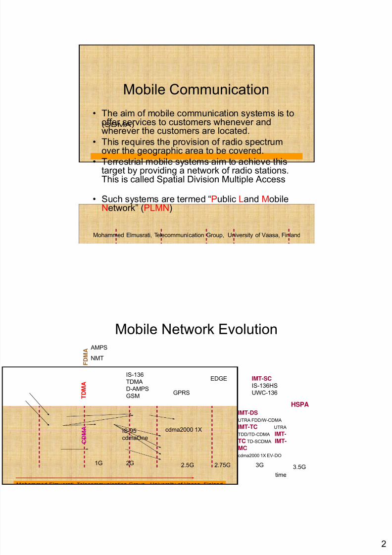
Mobile Network Evolution
F D M A
AMPS
NMT
T D M
A
IS-136
TDMA
D-AMPSGSM
IMT-DSUTRA FDD/W-CDMA
GPRS
EDGE IMT-SCIS-136HS
UWC-136
HSPA
1G 2G 2.5G 3G 3.5G
C D M A IMT-TC UTRA
TDD/TD-CDMA IMT-TC TD-SCDMA IMT-MCcdma2000 1X EV-DO
IS-95cdmaOne
cdma2000 1X
2.75G
time
8/7/2019 Mobile Picture
http://slidepdf.com/reader/full/mobile-picture 3/17
3
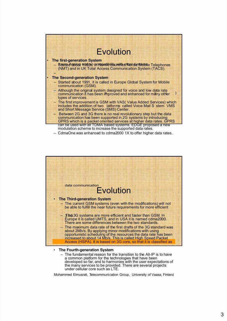
Evolution• The first-generation System – Started about 1980s, in Nordic countries Nordic Mobile Telephones
(NMT) and in UK Total Access Communication System (TACS).
– .
• The Second-generation System – Started about 1991, it is called in Europe Global System for Mobile
communication (GSM).
– Although the original system designed for voice and low data ratecommunication it has been improved and enhanced for many other types of services.
– The first improvement is GSM with VAS( Value Added Services) whichincludes the addition of two latforms called Voice Mail S stem VMS and Short Message Service (SMS) Center.
– Between 2G and 3G there is no real revolutionary step but the datacommunication has been supported in 2G systems by introducingGPRS which is a packet oriented services at higher data rates. GPRScan be used with all TDMA based systems. EDGE proposed a newmodulation scheme to increase the supported data rates.
– CdmaOne was enhanced to cdma2000 1X to offer higher data rates.
Evolution• The Third-generation System
– The current GSM systems (even with the modifications) will notbe able to fulfill the near future requirements for more efficient
.
– The 3G systems are more efficient and faster than GSM. InEurope it is called UMTS, and in USA it is named cdma2000.There are some differences between the two standards.
– The maximum data rate of the first drafts of the 3G standard wasabout 2Mb/s. By applying minor modifications with usingopportunistic scheduling of the resources the data rate has beenincreased to about 14 Mb/s. This is called High Speed PacketAccess (HSPA). It is based on 3G core, so that it is classified as.
• The Fourth-generation System – The fundamental reason for the transition to the All-IP is to have
a common platform for the technologies that have beendeveloped so far, and to harmonies with the user expectations of the many services to be provided. There are several projectsunder cellular core such as LTE.
Mohammed Elmusrati, Telecommunication Group, University of Vaasa, Finland
8/7/2019 Mobile Picture
http://slidepdf.com/reader/full/mobile-picture 4/17
4
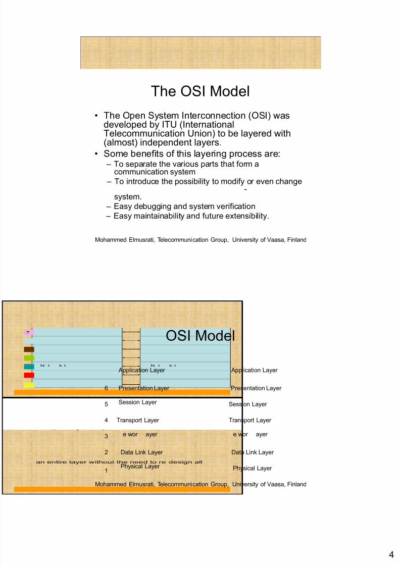
The OSI Model• The Open System Interconnection (OSI) was
developed by ITU (InternationalTelecommunication Union) to be layered with(almost) independent layers.
• Some benefits of this layering process are: – To separate the various parts that form a
communication system
– To introduce the possibility to modify or even change-
system. – Easy debugging and system verification
– Easy maintainability and future extensibility.
Mohammed Elmusrati, Telecommunication Group, University of Vaasa, Finland
OSI Model
Application Layer Application Layer
Transport Layer
Session Layer
Presentation Layer
Session Layer
Transport Layer
Presentation Layer
4
5
6
e wor ayer
Physical Layer Physical Layer
Data Link Layer
e wor ayer
Data Link Layer
1
3
2
Mohammed Elmusrati, Telecommunication Group, University of Vaasa, Finland
8/7/2019 Mobile Picture
http://slidepdf.com/reader/full/mobile-picture 5/17
5
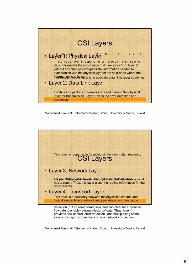
OSI Layers• Layer 1: Physical Layer
– e p ys ca ayer s respons e or e ac ua ransm ss on o
data. It transmits the information that it receives from layer 2
without any changes except for the information needed to
synchronize with the physical layer of the next node where the
information is to be sent.
• Layer 2: Data Link Layer – .
the data into packets or frames and send them to the physicallayer for transmission. Layer 2 does the error detection and
correction.
Mohammed Elmusrati, Telecommunication Group, University of Vaasa, Finland
OSI Layers
• Layer 3: Network Layer –
the path that a data packet has to take and the final destination ithas to reach. Thus, this layer gives the routing information for the
data packets.
• Layer 4: Transport Layer – This layer is a boundary between the physical elements and
logical elements in a network and provides a communication.
detection (but no error correction), and can cater for a reducedflow rate to enable re-transmission of data. Thus, layer 4provides flow control, error detection , and multiplexing of theseveral transport connections on one network connection.
Mohammed Elmusrati, Telecommunication Group, University of Vaasa, Finland
8/7/2019 Mobile Picture
http://slidepdf.com/reader/full/mobile-picture 6/17
6
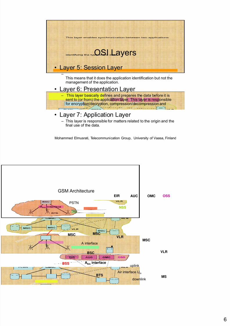
OSI Layers• Layer 5: Session Layer
– .This means that it does the application identification but not themanagement of the application.
• Layer 6: Presentation Layer – This layer basically defines and prepares the data before it is
sent to (or from) the application layer. This layer is responsiblefor encryption/decryption, compression/decompression and
.
• Layer 7: Application Layer – This layer is responsible for matters related to the origin and the
final use of the data.
Mohammed Elmusrati, Telecommunication Group, University of Vaasa, Finland
GSM Architecture
PSTN
NSS
EIR AUC OMC OSS
MSCVLR
MSC
MSC
A interface
VLRBSC
BTSAir interface Um
Abis interfaceBSSuplink
downlinkMS
8/7/2019 Mobile Picture
http://slidepdf.com/reader/full/mobile-picture 7/17
7
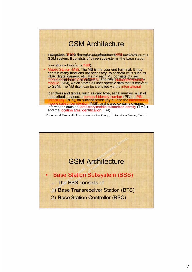
GSM Architecture• The previous slide shows a simplified functional architecture of a
GSM system. It consists of three subsystems, the base station, ,
operation subsystem (OSS).
• Mobile Station (MS): The MS is the user end terminal. It maycontain many functions not necessary to perform calls such asPDA, digital camera, etc. Mainly each MS consists of user independent hard- and software and of the subscriber identitymodule (SIM), which stores all user-specific data that is relevantto GSM. The MS itself can be identified via the international
. identifiers and tables, such as card type, serial number, a list of subscribed services, a personal identity number (PIN), a PINunlock key (PUK), an authentication key Ki, and the internationalmobile subscriber identity (IMSI), and it also contains dynamicinformation such as temporary mobile subscriber identity (TMSI)and the location area identification (LAI).
Mohammed Elmusrati, Telecommunication Group, University of Vaasa, Finland
GSM Architecture
• Base Station Subsystem (BSS)
– The BSS consists of
1) Base Transreceiver Station (BTS)2) Base Station Controller (BSC)
8/7/2019 Mobile Picture
http://slidepdf.com/reader/full/mobile-picture 8/17
8
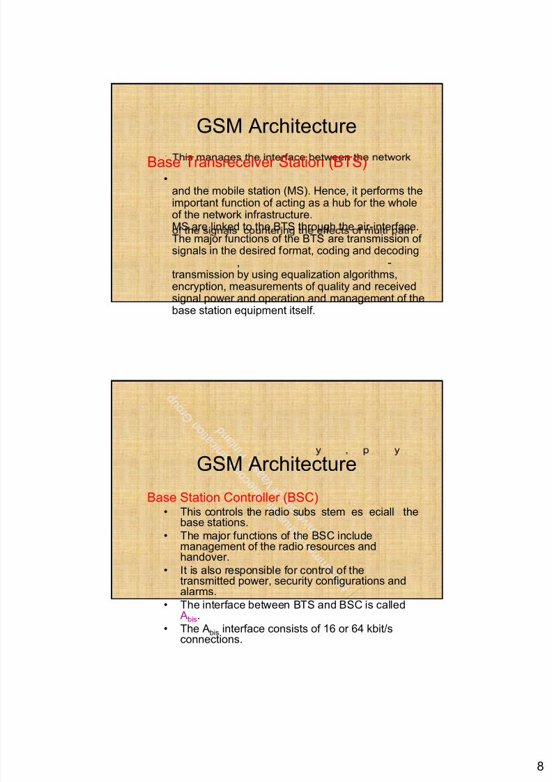
GSM ArchitectureBase Transreceiver Station (BTS)
•and the mobile station (MS). Hence, it performs theimportant function of acting as a hub for the wholeof the network infrastructure.MS are linked to the BTS through the air-interface.The major functions of the BTS are transmission of signals in the desired format, coding and decoding
, -
transmission by using equalization algorithms,encryption, measurements of quality and receivedsignal power and operation and management of thebase station equipment itself.
GSM Architecture
Base Station Controller (BSC)• This controls the radio subs stem es eciall the
base stations.
• The major functions of the BSC include
management of the radio resources andhandover.
• It is also responsible for control of thetransmitted power, security configurations andalarms.
• The interface between BTS and BSC is calledAbis.
• The Abis interface consists of 16 or 64 kbit/sconnections.
8/7/2019 Mobile Picture
http://slidepdf.com/reader/full/mobile-picture 9/17
9
GSM Architecture• Network Subsystem (NSS)
• The main components of the NSS are
– Mobile Switching Centre (MSC)
– Home Location Registrar (HLR)
– Visitor Location Registrar (VLR)
GSM Architecture
– Mobile Switching Centre (MSC):• The MSC is the sin le most im ortant element of
the NSS and it is responsible for the switchingfunctions that are necessary for interconnection
between mobile users and other mobile and fixednetwork users.
• It is like a normal Public Switched TelephoneNetwork (PSTN) exchange, but it needs to takeinto account of the mobility nature of customers.
,components, HLR, VLR, and AUC.
• The Gateway MSC (GMSC) is a normal MSC withthe additional functions necessary to interconnecta PLMN with other networks.

8/7/2019 Mobile Picture
http://slidepdf.com/reader/full/mobile-picture 10/17
10
GSM ArchitectureHome Location Register (HLR):
– The HLR contains the information related to
each mobile subscriber, such as the type of
subscription, services that the user can use,
the subscriber’s current location and the
mobile equipment status.
– The database in the HLR remains intact and
unchanged until the termination of the
subscription.
GSM Architecture
Visitor Location Register (VLR):
• The VLR comes into action once the subscriber
enters the coverage region.
• Unlike the HLR, the VLR is dynamic in nature and
interacts with the HLR when recording the data of
.
• When the subscriber moves to another region, the
database of the subscriber is also shifted to the
VLR of the new region.
8/7/2019 Mobile Picture
http://slidepdf.com/reader/full/mobile-picture 11/17
11
GSM Architecture• Operation Subsystem (OSS): The OSS
con a ns e necessary unc ons or
network operation and maintenance and it
consists of
– Operation and maintenance center (OMC)
– Authentication center AUC
– Equipment identity register (EIR)
GSM Architecture
Operation and maintenance center (OMC)
The OMC monitors and controls all other
network entities via the O interface (SS7 with
X.25).
Typical OMC management functions are traffic
monitoring, status reports of network entities,
su scr er an secur y managemen .
8/7/2019 Mobile Picture
http://slidepdf.com/reader/full/mobile-picture 12/17
12
GSM ArchitectureAuthentication Centre (AUC)
• e or s respons e or po c ng ac onsin the network.
• This has all the data required to protect thenetwork against false subscribers and to protectthe calls of regular subscribers.
• There are two major keys in the GSM standards:the encr tion of communication between mobile
users, and the authentication of the users.• The encryption keys are held in the mobile
equipment and the AUC and the information isprotected against unauthorized access.
GSM Architecture
Equipment Identity Registers (EIR)• Each item of mobile equipment has its own personal
identification, which is denoted by a number- the
International Mobile Equipment Identity (IMEI).• The number is installed during the manufacturing of
the equipment and states its conformation to the
GSM standards. Whenever a call is made, the
network checks the identity number; if this number
is not found on the approval list of authorized
equipments, access is denied.
• The EIR contains this list of authorized numbers
and allows the IMEI to be verified.
8/7/2019 Mobile Picture
http://slidepdf.com/reader/full/mobile-picture 13/17
13
GSM Architecture• Network Management System (NMS):
– The main task of the NMS is to ensure that
the running of the network is smooth. For this
purpose, it has four major tasks to perform
• Network Monitoring
• Network Development
• e wor easuremen s
• Fault Management
GSM Architecture
• GSM Interfaces
– There are three interface types:
1)Air interface
2)Abis interface
8/7/2019 Mobile Picture
http://slidepdf.com/reader/full/mobile-picture 14/17
14
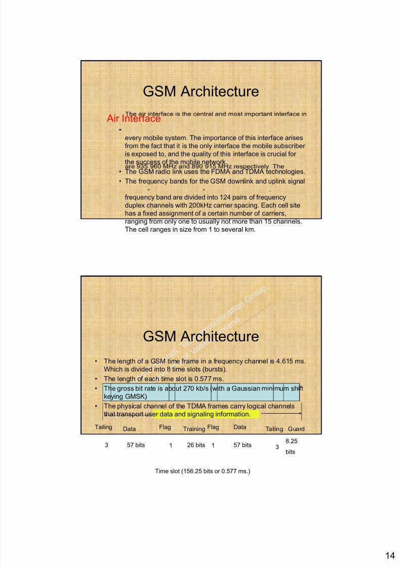
GSM ArchitectureAir Interface
•
every mobile system. The importance of this interface arises
from the fact that it is the only interface the mobile subscriber
is exposed to, and the quality of this interface is crucial for
the success of the mobile network.
• The GSM radio link uses the FDMA and TDMA technologies.
• The frequency bands for the GSM downlink and uplink signal
- - .
frequency band are divided into 124 pairs of frequencyduplex channels with 200kHz carrier spacing. Each cell site
has a fixed assignment of a certain number of carriers,
ranging from only one to usually not more than 15 channels.
The cell ranges in size from 1 to several km.
GSM Architecture
• The length of a GSM time frame in a frequency channel is 4.615 ms.
Which is divided into 8 time slots (bursts).
• The length of each time slot is 0.577 ms.
• The gross bit rate is about 270 kb/s (with a Gaussian minimum shift
keying GMSK)• The physical channel of the TDMA frames carry logical channels
that transport user data and signaling information.
Tailing Data Flag Training Flag Data Tailing Guard
3 57 bits 57 bits1 126 bits 38.25
bits
Time slot (156.25 bits or 0.577 ms.)
8/7/2019 Mobile Picture
http://slidepdf.com/reader/full/mobile-picture 15/17
15
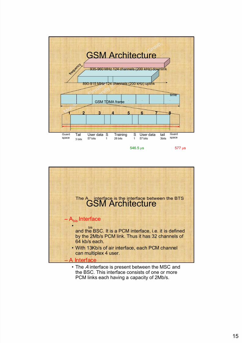
GSM Architecture935-960 MHz 124 channels (200 kHz) downlink
890-915 MHz 124 channels (200 kHz) uplink
time
GSM TDMA frame
1 2 3 4 5 6 7 8
546.5 μs
Tail
3 bits
tail3bits
User data57 bits
User data57 bits
Training26 bits
S1
S1
Guard
space
Guard
space
577 μs
GSM Architecture
– Abis Interface• bis
and the BSC. It is a PCM interface, i.e. it is definedby the 2Mb/s PCM link. Thus it has 32 channels of
64 kb/s each.• With 13Kb/s of air interface, each PCM channel
can multiplex 4 user.
– A Interface• The A interface is present between the MSC and
the BSC. This interface consists of one or morePCM links each having a capacity of 2Mb/s.
8/7/2019 Mobile Picture
http://slidepdf.com/reader/full/mobile-picture 16/17
16
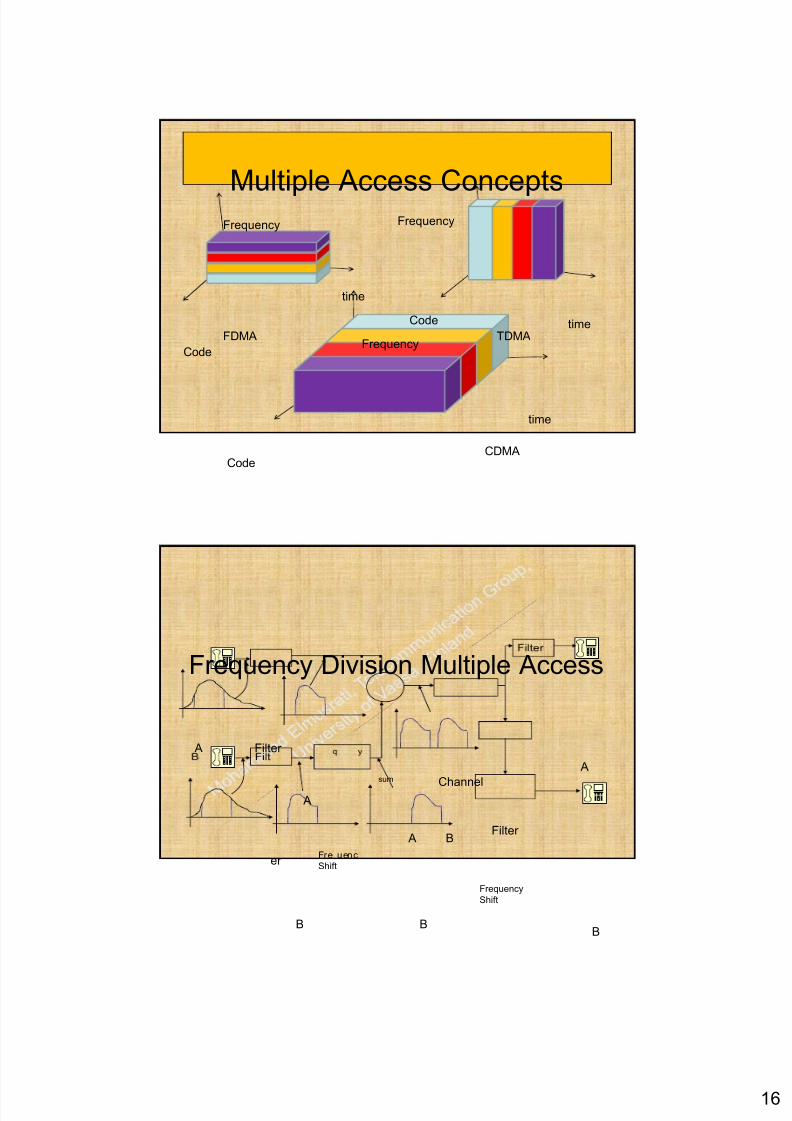
Multiple Access ConceptsFrequency Frequency
time
time
FrequencyCode
Code
FDMA TDMA
time
CodeCDMA
Frequency Division Multiple Access
Filter
Fre uenc
Channelsum
A
A
A B
A
Filter
er
Shift
B BB
Frequency
Shift
8/7/2019 Mobile Picture
http://slidepdf.com/reader/full/mobile-picture 17/17
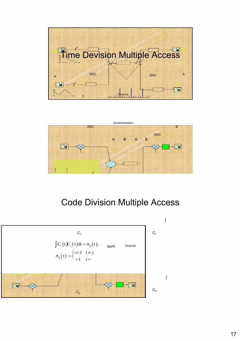
Time Devision Multiple AccessADC DACA
A
Channelt
ADC
DAC
Synchronization
A AB B
B
Code Division Multiple Access
∫
C1
Channel
C1
sum( ) ( ) ( )
( )
i j ij
ij
C t C dt ,
1 i j
1 i
τ = σ τ
<< ≠⎧σ τ = ⎨
= =
∫
C2
C2
∫