Embed Size (px)
Citation preview

ORIGINAL ARTICLE
Mobile spatial coordinate measuring system (MScMS)and CMMs: a structured comparison
Fiorenzo Franceschini & Domenico Maisano &
Luca Mastrogiacomo
Received: 20 February 2008 /Accepted: 18 July 2008# Springer-Verlag London Limited 2008
Abstract In many branches of industry, most of manufac-turing efforts are directed toward producing objects ofspecific forms and dimensions. Dimensional measurementis an important part of the production cycle, to checkproducts compliance with specifications. For this, manysubstantial improvements in the existing technologies havebeen made, and new measuring systems have beenintroduced. This paper briefly introduces a recent measur-ing system—mobile spatial coordinate measuring system(MScMS)—which is suitable for performing dimensionalmeasurements of large-size objects (dimension on the orderof tens of meters). MScMS, thanks to its distributedwireless sensor network nature, is portable and can beeasily arranged around the measured object. Furthermore, itdoes not require complex setup operations before beingready to perform measurements. After describing how thesystem works, we will compare it with well-tested andwidespread instruments such as traditional coordinatemeasuring machines (CMMs), showing analogies anddifferences. The comparison is structured on the basis ofdifferent criteria, which are analyzed in detail in the firstpart of the paper. Although being able to perform similarmeasurements, CMMs and MScMS are different in tech-nological features. CMMs are able to achieve higher levelof accuracy, while MScMS is more flexible, cheap, and canbe important to simplify the current measuring practiceswithin large-scale industrial metrology. It can be concludedthat these systems can easily coexist, as each system issuitable for specific applications.
Keywords Mobile measuring system . Dimensionalmetrology . Large-scale metrology .Wireless sensornetwork . Coordinate measuring machine (CMM)
1 Introduction
This paper arises from the research activity developed at theindustrial metrology and quality engineering laboratory ofDepartment of Production Systems and Business Econom-ics—Politecnico di Torino, on a new system prototype fordimensional measurement called mobile spatial coordinatemeasuring system (MScMS) [8]. MScMS determinesdimensional features of large-size objects and has beendesigned to overcome some limits shown by otherwidespread measuring systems used nowadays, such ascoordinate measuring machines (CMMs), theodolites/tacheometers, photogrammetry equipments, global posi-tioning system (GPS)-based systems, and laser-trackers[2, 22].
Basing on a distributed sensor networks structure,MScMS can accomplish rapid dimensional measurementsin a wide range of indoor operating environments. It consistsof distributed wireless devices communicating with eachother through radiofrequency (RF) and ultrasound (US)transceivers. This frame makes the system easy to handle andto move and gives the possibility of placing its componentsfreely around the workpiece. Wireless devices known as“Crickets” are developed by the Massachusetts Institute ofTechnology. Being quite small, light, and potentially cheap(if mass produced), they fit to obtain a wide range of differentnetwork configurations [21, 1].
These features make the new system suitable forparticular types of measurement, which cannot be carriedout, for example, by conventional CMMs. Typical is the
Int J Adv Manuf TechnolDOI 10.1007/s00170-008-1677-0
F. Franceschini (*) :D. Maisano : L. MastrogiacomoDipartimento di Sistemi di Produzione ed Economia dell’Azienda,Politecnico di Torino,Corso Duca degli Abruzzi 24,10129 Turin, Italye-mail: [email protected]
case of large-size objects that are unable to be transferred tothe measuring system area (because of their dimensions orother logistical constraints) and thus require the measuringsystem to be moved to them. This aspect will beemphasized below.
The goal of this paper is comparing MScMS with well-tested and popular instruments such as classical CMMs.MScMS and classical CMMs have many common aspects.For both the systems, measurements are taken touching fewpoints on the objects surface with a probe tip. Furthermore,points are defined on a Cartesian coordinate system andthen coordinates are processed by specific algorithms, todetermine geometrical features, angles, other objects shapesetc. On the other hand, MScMS and CMMs have manydifferent characteristics: their physical structure, size, cost,etc. This comparison will be carried out according to astructured set of evaluation criteria.
The article is organized in five sections. Section 2focuses on the new paradigm of the distributed measuringsystems within large-scale metrology. Section 3 provides abrief introduction to the MScMS technological features andmodus operandi. Section 4 refers to CMMs main character-istics. Section 5 illustrates the criteria for comparingMScMS and classical CMMs. Section 6 shows the resultsof this comparison. Finally, the future direction of theresearch activity is outlined.
2 The new paradigm of the distributed measuringsystems
The field of large-scale metrology can be defined as themetrology of large machines and structures that is to say“the metrology of objects in which the linear dimensionsrange from tens to hundreds of meters” [23]. There is anincreasing trend for accurate measurement of length, inparticular, the 3D coordinate metrology at length scales of 5to 100 m has become a routine requirement in industriessuch as aircraft and ship construction. There have beensignificant advances across a broad range of technologies,including laser interferometery, absolute distance metrolo-gy, very high density charge-coupled device cameras, andso on. In this paper, for the purpose of discussion, we canclassify the measurement systems into centralized anddistributed systems. In the case of centralized instruments,measurements may independently arise by a single stand-alone unit, which is a centralized complete system (i.e., aCMM, a laser scanner or a laser tracker), while distributedinstruments are made of two or more distributed units (likeMScMS). In general, distributed measurement systems, dueto their nature, are portable and can be easily transferredaround the area where the measurand is. Furthermore,compared to centralized systems, distributed systems may
cover larger measuring areas, with no need for reposition-ing the instrumentation devices around the measured object[12].
MScMS is a modular, measuring system for largevolume objects. Even if, at present time, MScMS is still aprototype and needs to be further developed, the systemenables factory-wide location of multiple objects, applica-ble in manufacturing and assembly. Mainly, it can be usedby aerospace manufacturers, but can also be adopted byautomotive and industrial manufacturers both for position-ing and tracking applications. As MScMS main compo-nents are a number of wireless devices distributed aroundthe measuring area, this not rigidly connected frame makesthe system easy to handle and to move and gives thepossibility of placing its components freely around theworkpiece, adapting to the environment and not requiringparticular facilities. Consequently, MScMS is suitable forparticular types of measurement that cannot be carried outby traditional frame instruments, like conventional CMMs,which are bulky and cannot be moved. The introduction ofdistributed measuring systems will probably have importanteffects on simplifying the current measuring practiceswithin large-scale industrial metrology [15]. This tendencyis confirmed by other recent distributed measuring systemsbased on laser and optical technology: the indoor GPS andthe portable CMM [25, 28, 29].
3 MScMS technological and management features
The MScMS prototype is constituted by three maincomponents:
– a constellation (network) of wireless devices, arrangedaround the working area;
– a measuring probe, communicating with constellationdevices to obtain the coordinates of the touched points;
– a control and computing system, able to receive andprocess data obtained by the measuring probe, toevaluate objects geometrical features.
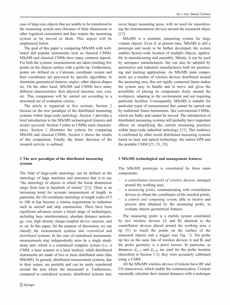
The measuring probe is a mobile system constitutedby two wireless devices (A and B) identical to theconstellation devices placed around the working area, atip (V) to touch the points on the surface of themeasured objects and a trigger (see Fig. 1). The probetip lies on the same line of wireless devices A and B, andthe probe geometry is a priori known. In particular, asdistances dA–V and dA–B are used for the probe location(described in Section 5.3), they were accurately calibratedusing a CMM.
All the MScMS wireless devices (Crickets) have RF andUS transceivers, which enable the communication. Cricketsrepeatedly calculate their mutual distances with a technique
Int J Adv Manuf Technol
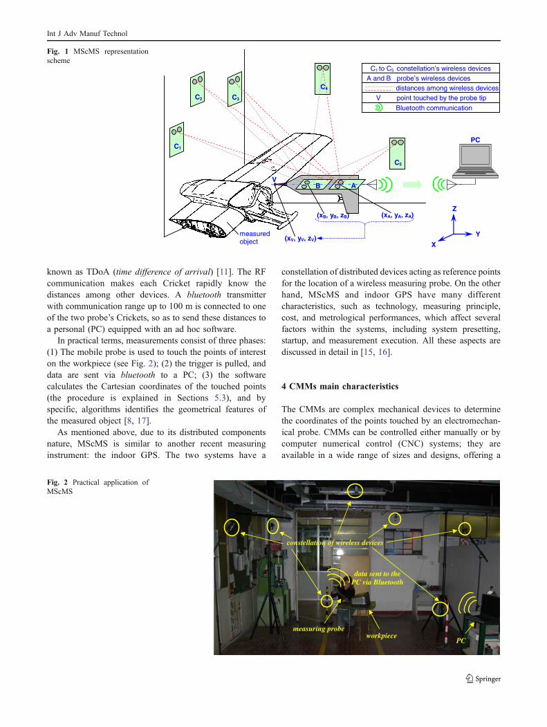
known as TDoA (time difference of arrival) [11]. The RFcommunication makes each Cricket rapidly know thedistances among other devices. A bluetooth transmitterwith communication range up to 100 m is connected to oneof the two probe’s Crickets, so as to send these distances toa personal (PC) equipped with an ad hoc software.
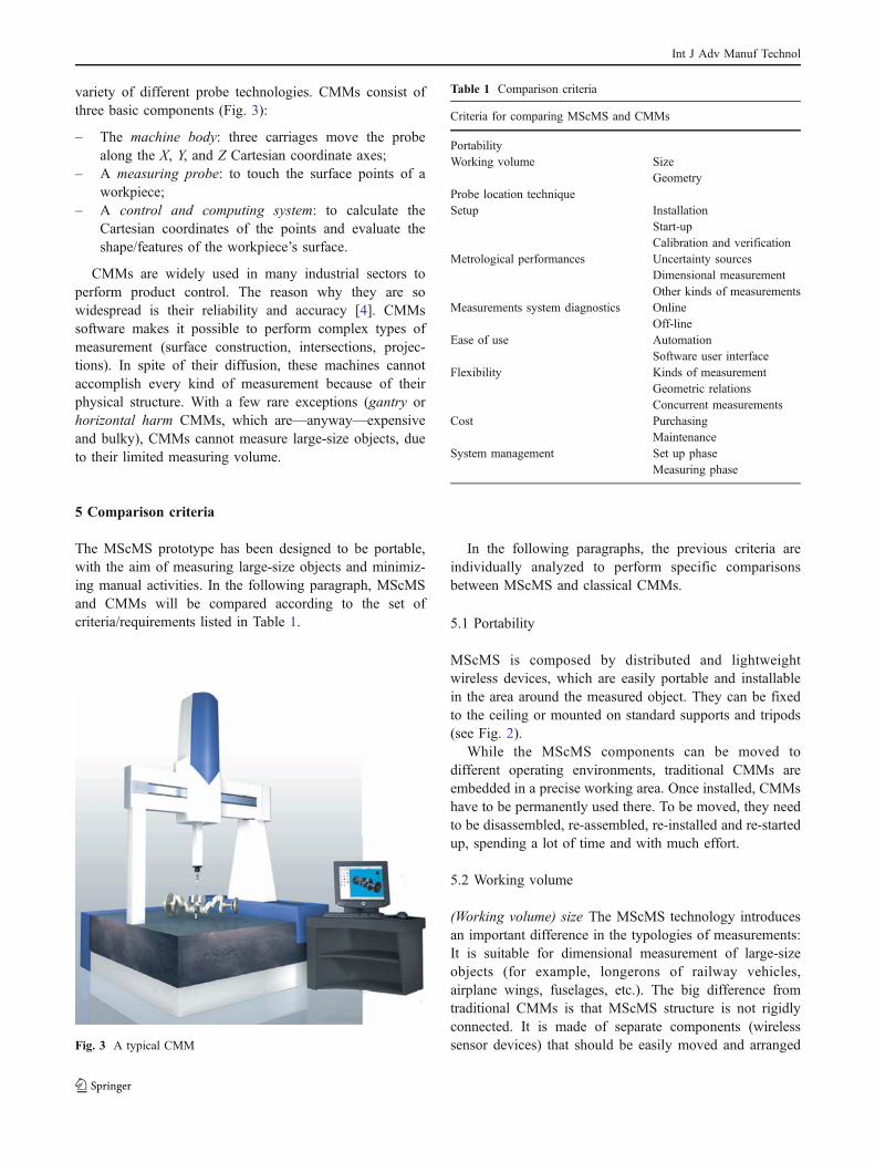
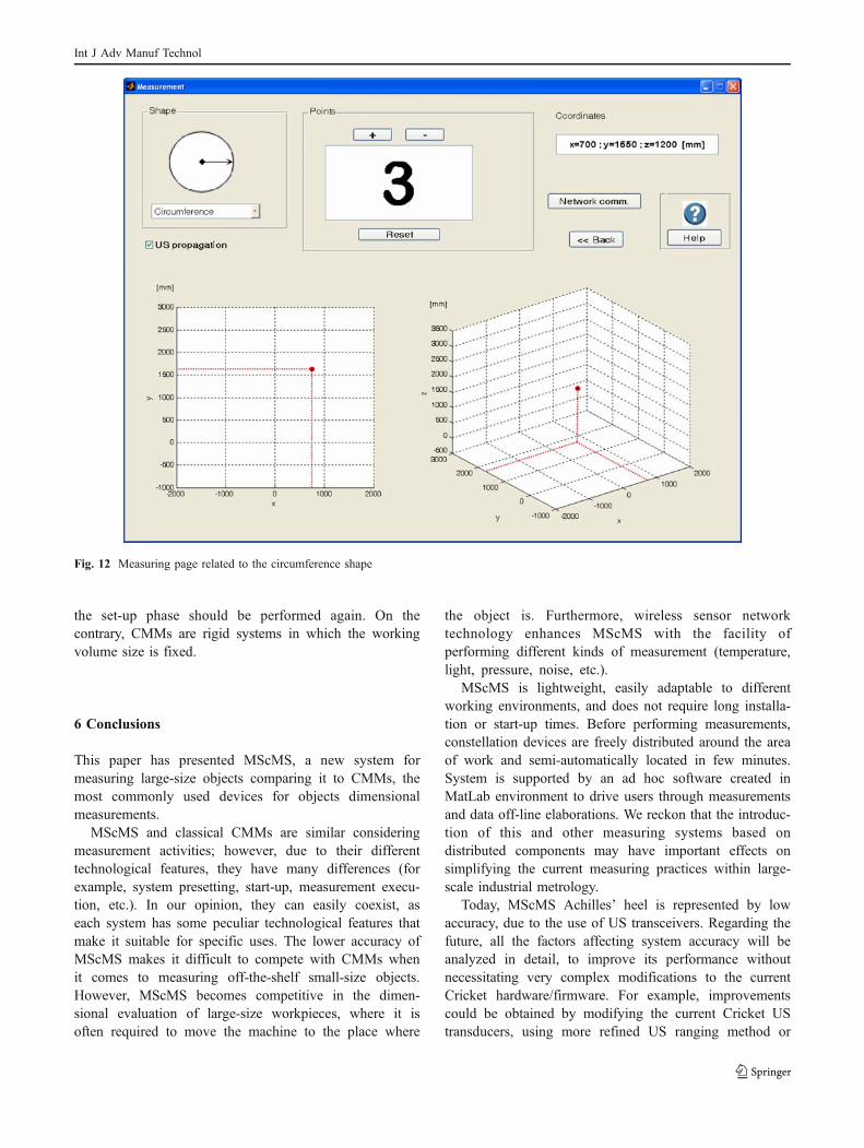
In practical terms, measurements consist of three phases:(1) The mobile probe is used to touch the points of intereston the workpiece (see Fig. 2); (2) the trigger is pulled, anddata are sent via bluetooth to a PC; (3) the softwarecalculates the Cartesian coordinates of the touched points(the procedure is explained in Sections 5.3), and byspecific, algorithms identifies the geometrical features ofthe measured object [8, 17].
As mentioned above, due to its distributed componentsnature, MScMS is similar to another recent measuringinstrument: the indoor GPS. The two systems have a
constellation of distributed devices acting as reference pointsfor the location of a wireless measuring probe. On the otherhand, MScMS and indoor GPS have many differentcharacteristics, such as technology, measuring principle,cost, and metrological performances, which affect severalfactors within the systems, including system presetting,startup, and measurement execution. All these aspects arediscussed in detail in [15, 16].
4 CMMs main characteristics
The CMMs are complex mechanical devices to determinethe coordinates of the points touched by an electromechan-ical probe. CMMs can be controlled either manually or bycomputer numerical control (CNC) systems; they areavailable in a wide range of sizes and designs, offering a
data sent to the PC via Bluetooth
constellation of wireless devices
measuring probe
PC workpiece
Fig. 2 Practical application ofMScMS
C5
C4
C3 C2
C1
(xB, yB, zB) (xA, yA, zA)
(xV, yV, zV) Y
X
Z
C1 to C5 constellation’s wireless devices A and B probe’s wireless devices
distances among wireless devices
B A
PC
measured object
V
Bluetooth communication
V point touched by the probe tip
Fig. 1 MScMS representationscheme
Int J Adv Manuf Technol
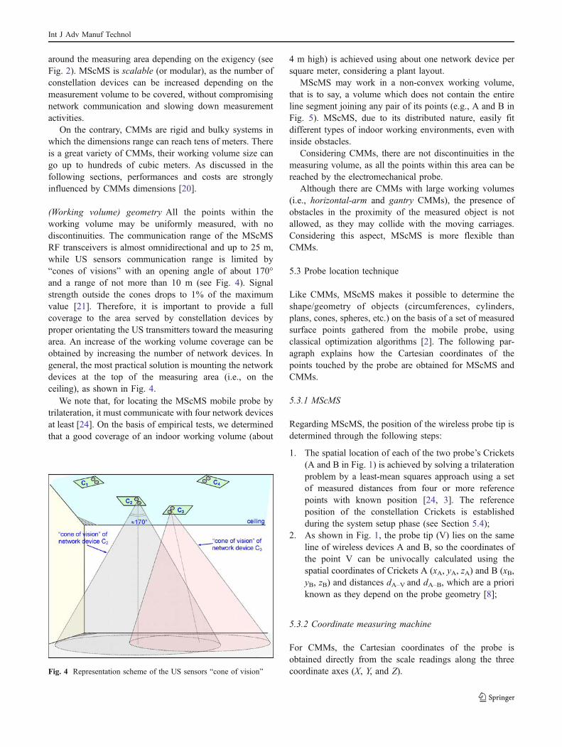
variety of different probe technologies. CMMs consist ofthree basic components (Fig. 3):
– The machine body: three carriages move the probealong the X, Y, and Z Cartesian coordinate axes;
– A measuring probe: to touch the surface points of aworkpiece;
– A control and computing system: to calculate theCartesian coordinates of the points and evaluate theshape/features of the workpiece’s surface.
CMMs are widely used in many industrial sectors toperform product control. The reason why they are sowidespread is their reliability and accuracy [4]. CMMssoftware makes it possible to perform complex types ofmeasurement (surface construction, intersections, projec-tions). In spite of their diffusion, these machines cannotaccomplish every kind of measurement because of theirphysical structure. With a few rare exceptions (gantry orhorizontal harm CMMs, which are—anyway—expensiveand bulky), CMMs cannot measure large-size objects, dueto their limited measuring volume.
5 Comparison criteria
The MScMS prototype has been designed to be portable,with the aim of measuring large-size objects and minimiz-ing manual activities. In the following paragraph, MScMSand CMMs will be compared according to the set ofcriteria/requirements listed in Table 1.
In the following paragraphs, the previous criteria areindividually analyzed to perform specific comparisonsbetween MScMS and classical CMMs.
5.1 Portability
MScMS is composed by distributed and lightweightwireless devices, which are easily portable and installablein the area around the measured object. They can be fixedto the ceiling or mounted on standard supports and tripods(see Fig. 2).
While the MScMS components can be moved todifferent operating environments, traditional CMMs areembedded in a precise working area. Once installed, CMMshave to be permanently used there. To be moved, they needto be disassembled, re-assembled, re-installed and re-startedup, spending a lot of time and with much effort.
5.2 Working volume
(Working volume) size The MScMS technology introducesan important difference in the typologies of measurements:It is suitable for dimensional measurement of large-sizeobjects (for example, longerons of railway vehicles,airplane wings, fuselages, etc.). The big difference fromtraditional CMMs is that MScMS structure is not rigidlyconnected. It is made of separate components (wirelesssensor devices) that should be easily moved and arranged
Table 1 Comparison criteria
Criteria for comparing MScMS and CMMs
PortabilityWorking volume Size
GeometryProbe location techniqueSetup Installation
Start-upCalibration and verification
Metrological performances Uncertainty sourcesDimensional measurementOther kinds of measurements
Measurements system diagnostics OnlineOff-line
Ease of use AutomationSoftware user interface
Flexibility Kinds of measurementGeometric relationsConcurrent measurements
Cost PurchasingMaintenance
System management Set up phaseMeasuring phase
Fig. 3 A typical CMM
Int J Adv Manuf Technol
around the measuring area depending on the exigency (seeFig. 2). MScMS is scalable (or modular), as the number ofconstellation devices can be increased depending on themeasurement volume to be covered, without compromisingnetwork communication and slowing down measurementactivities.
On the contrary, CMMs are rigid and bulky systems inwhich the dimensions range can reach tens of meters. Thereis a great variety of CMMs, their working volume size cango up to hundreds of cubic meters. As discussed in thefollowing sections, performances and costs are stronglyinfluenced by CMMs dimensions [20].
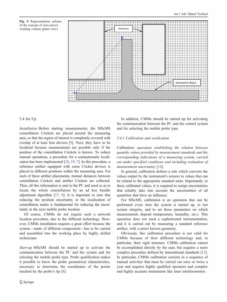
(Working volume) geometry All the points within theworking volume may be uniformly measured, with nodiscontinuities. The communication range of the MScMSRF transceivers is almost omnidirectional and up to 25 m,while US sensors communication range is limited by“cones of visions” with an opening angle of about 170°and a range of not more than 10 m (see Fig. 4). Signalstrength outside the cones drops to 1% of the maximumvalue [21]. Therefore, it is important to provide a fullcoverage to the area served by constellation devices byproper orientating the US transmitters toward the measuringarea. An increase of the working volume coverage can beobtained by increasing the number of network devices. Ingeneral, the most practical solution is mounting the networkdevices at the top of the measuring area (i.e., on theceiling), as shown in Fig. 4.
We note that, for locating the MScMS mobile probe bytrilateration, it must communicate with four network devicesat least [24]. On the basis of empirical tests, we determinedthat a good coverage of an indoor working volume (about
4 m high) is achieved using about one network device persquare meter, considering a plant layout.
MScMS may work in a non-convex working volume,that is to say, a volume which does not contain the entireline segment joining any pair of its points (e.g., A and B inFig. 5). MScMS, due to its distributed nature, easily fitdifferent types of indoor working environments, even withinside obstacles.
Considering CMMs, there are not discontinuities in themeasuring volume, as all the points within this area can bereached by the electromechanical probe.
Although there are CMMs with large working volumes(i.e., horizontal-arm and gantry CMMs), the presence ofobstacles in the proximity of the measured object is notallowed, as they may collide with the moving carriages.Considering this aspect, MScMS is more flexible thanCMMs.
5.3 Probe location technique
Like CMMs, MScMS makes it possible to determine theshape/geometry of objects (circumferences, cylinders,plans, cones, spheres, etc.) on the basis of a set of measuredsurface points gathered from the mobile probe, usingclassical optimization algorithms [2]. The following par-agraph explains how the Cartesian coordinates of thepoints touched by the probe are obtained for MScMS andCMMs.
5.3.1 MScMS
Regarding MScMS, the position of the wireless probe tip isdetermined through the following steps:
1. The spatial location of each of the two probe’s Crickets(A and B in Fig. 1) is achieved by solving a trilaterationproblem by a least-mean squares approach using a setof measured distances from four or more referencepoints with known position [24, 3]. The referenceposition of the constellation Crickets is establishedduring the system setup phase (see Section 5.4);
2. As shown in Fig. 1, the probe tip (V) lies on the sameline of wireless devices A and B, so the coordinates ofthe point V can be univocally calculated using thespatial coordinates of Crickets A (xA, yA, zA) and B (xB,yB, zB) and distances dA–V and dA–B, which are a prioriknown as they depend on the probe geometry [8];
5.3.2 Coordinate measuring machine
For CMMs, the Cartesian coordinates of the probe isobtained directly from the scale readings along the threecoordinate axes (X, Y, and Z).Fig. 4 Representation scheme of the US sensors “cone of vision”
Int J Adv Manuf Technol
5.4 Set Up
Installation Before starting measurements, the MScMSconstellation Crickets are placed around the measuringarea, so that the region of interest is completely covered withoverlap of at least four devices [9]. Next, they have to belocalized because measurements are possible only if theposition of the constellation Crickets is known. To reducemanual operations, a procedure for a semiautomatic locali-zation has been implemented [18, 19, 7]. In this procedure, areference artifact equipped with some Cricket devices isplaced in different positions within the measuring area. Foreach of these artifact placements, mutual distances betweenconstellation Crickets and artifact Crickets are collected.Then, all this information is sent to the PC and used so as tolocate the whole constellation by an ad hoc bundleadjustment algorithm [17, 8]. It is important to note thatreducing the position uncertainty in the localization ofconstellation nodes is fundamental for reducing the uncer-tainty in the next mobile probe location.
Of course, CMMs do not require such a networklocation procedure, due to the different technology. How-ever, CMMs installation requires a great effort because thesystem—made of different components—has to be carriedand assembled into the working place by highly skilledtechnicians.
Start-up MScMS should be started up to activate thecommunication between the PC and the system and forselecting the mobile probe type. Probe qualification makesit possible to know the probe geometrical characteristics,necessary to determine the coordinates of the pointstouched by the probe’s tip [8].
In addition, CMMs should be started up for activatingthe communication between the PC and the control systemand for selecting the mobile probe type.
5.4.1 Calibration and verification
Calibration: operation establishing the relation betweenquantity values provided by measurement standards and thecorresponding indications of a measuring system, carriedout under specified conditions and including evaluation ofmeasurement uncertainty [14].
In general, calibration defines a rule which converts thevalues output by the instrument’s sensors to values that canbe related to the appropriate standard units. Importantly, tothese calibrated values, it is required to assign uncertaintiesthat reliably take into account the uncertainties of allquantities that have an influence.
For MScMS, calibration is an operation that can beperformed every time the system is started up, to testsystem integrity, and to set those parameters on whichmeasurements depend (temperature, humidity, etc.). Thisoperation does not need a sophisticated instrumentation,and it is carried out by measuring a standard referenceartifact, with a priori known geometry.
Obviously, this calibration procedure is not valid forCMMs because of their different technology and, inparticular, their rigid structure. CMMs calibration cannotbe accomplished directly by the user, but requires a morecomplex procedure defined by international standards [13].In particular, CMMs calibration consists in a sequence ofmanual activities that must be carried out once or twice ayear and requires highly qualified operators and complexand highly accurate instruments like laser interferometers.
measured object
A
B
obstacles
Fig. 5 Representation schemeof the concept of non-convexworking volume (plant view)
Int J Adv Manuf Technol

Verification: confirmation through examination of agiven item and provision of objective evidence that it fulfilsspecified requirements [14].
Another activity to make MScMS suitable for themeasurement is the system verification (block 11 in Fig. 7).It should be periodically performed to verify and adjust themeasuring scale adopted (for example, the US speedchanges with air temperature and humidity). This operationis performed by the use of a standard reference artifact [13].
CMMs verification is done using some standard refer-ence artifacts or repeatedly measuring the same points toevaluate possible measurements drifts. Different approacheshave been proposed in this direction [5]. Whenever a CMMdoes not fulfill specified requirements, highly qualifiedoperators have to intervene.
5.5 Metrological performances
Uncertainty sources The technology employed is responsi-ble for MScMS’s large uncertainty compared to CMMs [8].MScMS measurement uncertainty may change dependingon many different factors related to the use of UStransceivers, such as temperature, humidity, air turbulence,transducer geometry, transducer bandwidth, and US signaldetection method [3]. Furthermore, US signals may bediffracted and reflected by obstacles interposed betweentwo devices. However, most of these negative aspects canbe effectively corrected/limited by the implementation ofcompensation/correction models [6, 3].
Furthermore, CMMs performances may change depend-ing on many factors like machine dimensions and stiffness,climatic conditions (temperature and humidity), or speed ofcontact between the probe and the workpiece. Nevertheless,CMMs uncertainty is some order of magnitude smaller thanMScMS.
5.6 Dimensional measurement
5.6.1 Mobile spatial coordinate measuring system
To give an idea of MScMS prototype performances, twotests have been carried out:
1. Repeatability test: A single point within the workingvolume is measured repeatedly about 50 times, leavingthe mobile probe in a fixed position. The test isrepeated measuring at least 20 different points indifferent areas of the working volume. For each point,the standard deviations (σx, σy, σz) related to theregistered Cartesian coordinates (x, y, z) is calculated.
2. Reproducibility test: This test is similar to the previousone, but the mobile-probe orientation is changed beforeeach measurement—with the aim of approaching each
point from a different direction. Furthermore, thedifferent measurements are performed under differentconditions (i.e., by different operators and in differentintervals of time).
3. Distance error test: This test is performed using areference artifact consisting of a bar with knownlength. The nominal length of the bar (around 3 m)is calibrated using a laser interferometer, which is atleast four orders of magnitude more accurate thanMScMS. The bar length is measured 20 times for tendifferent positions/orientations within the workingvolume. The standard deviation related to thedistance residuals (σD), that is to say the differencesbetween nominal distance and distances measured withMScMS are calculated.
Results of these preliminary tests are reported in Table 2.
5.6.2 Coordinate measuring machine
To provide an example of CMMs standard performance,Table 3 reports the maximum permitted error (MPE) ondistance measurements related to a DEA™ machine [27].In general, the MPE grows up with the dimension of theCMM.
Other kinds of measurements While CMMs have beendesigned with the purpose of performing only dimensionalmeasurement, MScMS can carry out other kinds ofmeasurements. Actually, Cricket devices may be equippedwith other sensor boards. This gives the possibility toassociate single position measurements with other kinds ofmeasurements, such as light intensity, temperature, acceler-ation, magnetic field, pressure, humidity, or noise pollution.Accuracy of these kinds of measurements depends onembedded sensors utilized [26].
5.7 Measurements system diagnostics
Online measurements diagnostics As said before, MScMSis sensitive to external factors, such as environmentalconditions (temperature, humidity, and presence ofobstacles among distributed devices). MScMS softwareprovides some diagnostic tools to control the measurements
Table 2 Results of the MScMS preliminary tests (with reference tosingle sampling measurements)
Test Repeatability Reproducibility Distanceerror
Mean standarddeviation (mm)
σx σy σz σx σy σz σD4.8 5.1 3.5 7.3 7.8 4.1 8.0
Int J Adv Manuf Technol
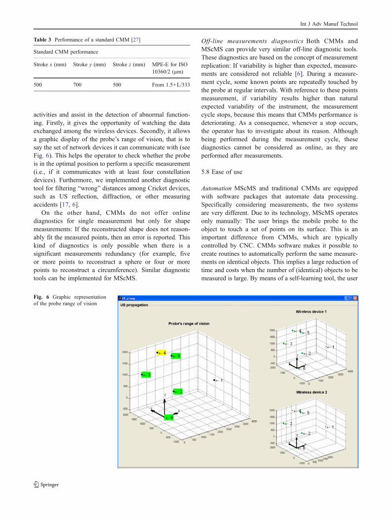
activities and assist in the detection of abnormal function-ing. Firstly, it gives the opportunity of watching the dataexchanged among the wireless devices. Secondly, it allowsa graphic display of the probe’s range of vision, that is tosay the set of network devices it can communicate with (seeFig. 6). This helps the operator to check whether the probeis in the optimal position to perform a specific measurement(i.e., if it communicates with at least four constellationdevices). Furthermore, we implemented another diagnostictool for filtering “wrong” distances among Cricket devices,such as US reflection, diffraction, or other measuringaccidents [17, 6].
On the other hand, CMMs do not offer onlinediagnostics for single measurement but only for shapemeasurements: If the reconstructed shape does not reason-ably fit the measured points, then an error is reported. Thiskind of diagnostics is only possible when there is asignificant measurements redundancy (for example, fiveor more points to reconstruct a sphere or four or morepoints to reconstruct a circumference). Similar diagnostictools can be implemented for MScMS.
Off-line measurements diagnostics Both CMMs andMScMS can provide very similar off-line diagnostic tools.These diagnostics are based on the concept of measurementreplication: If variability is higher than expected, measure-ments are considered not reliable [6]. During a measure-ment cycle, some known points are repeatedly touched bythe probe at regular intervals. With reference to these pointsmeasurement, if variability results higher than naturalexpected variability of the instrument, the measurementcycle stops, because this means that CMMs performance isdeteriorating. As a consequence, whenever a stop occurs,the operator has to investigate about its reason. Althoughbeing performed during the measurement cycle, thesediagnostics cannot be considered as online, as they areperformed after measurements.
5.8 Ease of use
Automation MScMS and traditional CMMs are equippedwith software packages that automate data processing.Specifically considering measurements, the two systemsare very different. Due to its technology, MScMS operatesonly manually: The user brings the mobile probe to theobject to touch a set of points on its surface. This is animportant difference from CMMs, which are typicallycontrolled by CNC. CMMs software makes it possible tocreate routines to automatically perform the same measure-ments on identical objects. This implies a large reduction oftime and costs when the number of (identical) objects to bemeasured is large. By means of a self-learning tool, the user
Table 3 Performance of a standard CMM [27]
Standard CMM performance
Stroke x (mm) Stroke y (mm) Stroke z (mm) MPE-E for ISO10360/2 (µm)
500 700 500 From 1.5+L/333
Fig. 6 Graphic representationof the probe range of vision
Int J Adv Manuf Technol
can also choose to manually measure the first objectallowing the system to learn the measurement patch to berepeated.
The MScMS software does not provide the same facility,due to the manual nature of measurements.
Software user interface Both devices (CMMs and MScMS)provide a software user interface. Their functions are basedon a similar structure, with the aim of guiding the userthrough the various activities. Table 4 summarizes theresults of a comparison between the MScMS and CMMssoftware user interfaces.
As for CMMs, MScMS software has been developed tohelp operators by:
– leading them through the start-up and measuringactivities;
– providing tools and functions that simplify their work;– displaying the results in a clear and complete way.
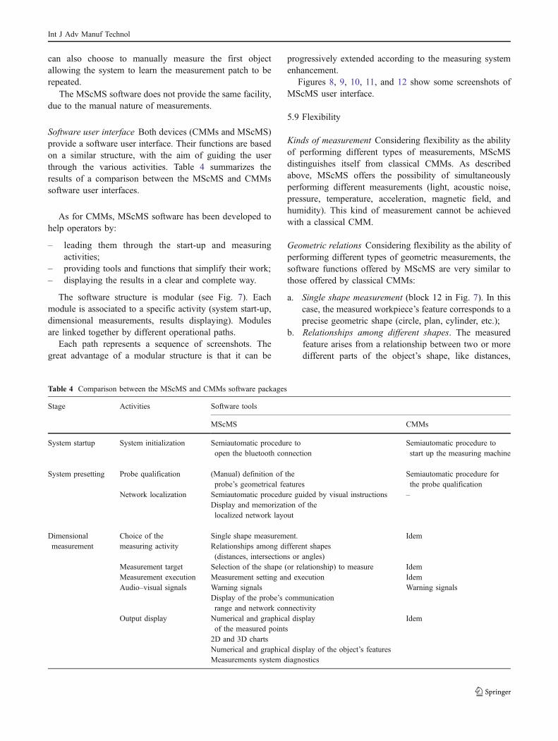
The software structure is modular (see Fig. 7). Eachmodule is associated to a specific activity (system start-up,dimensional measurements, results displaying). Modulesare linked together by different operational paths.
Each path represents a sequence of screenshots. Thegreat advantage of a modular structure is that it can be
progressively extended according to the measuring systemenhancement.
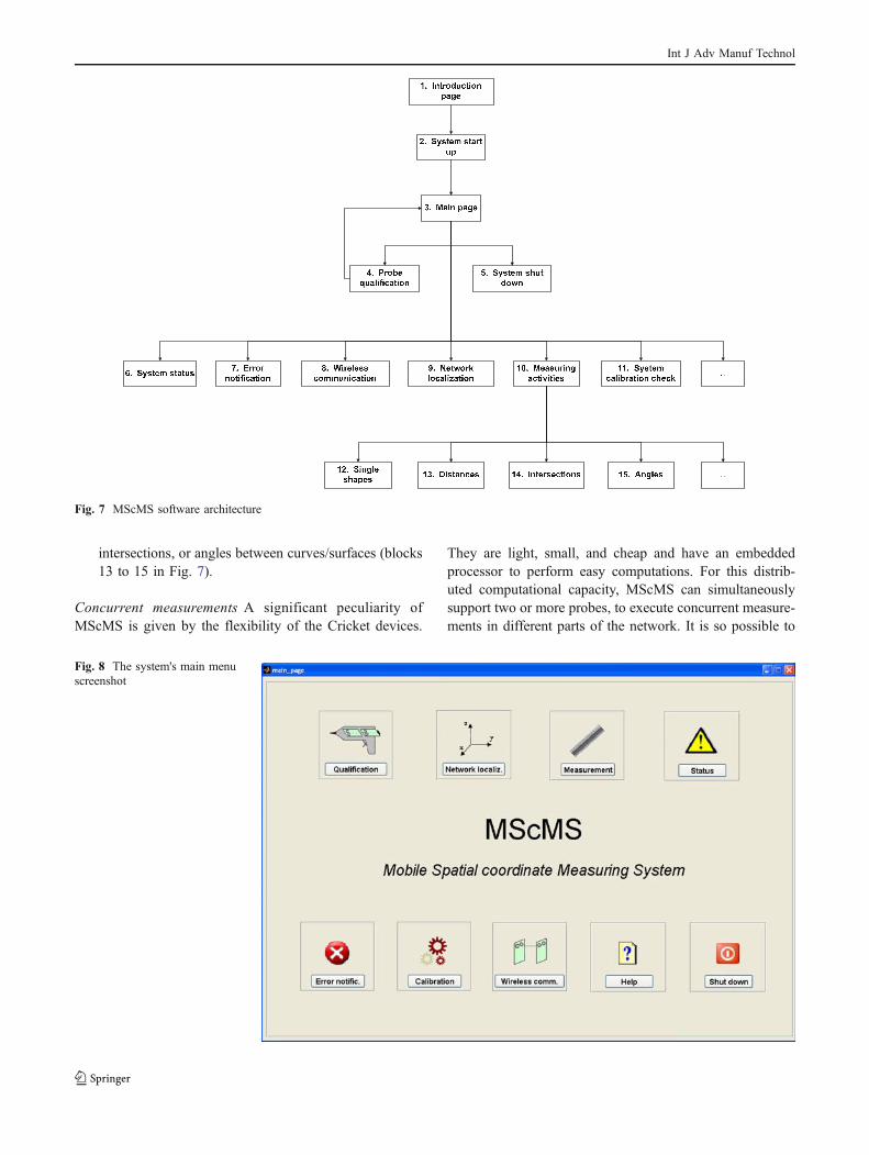
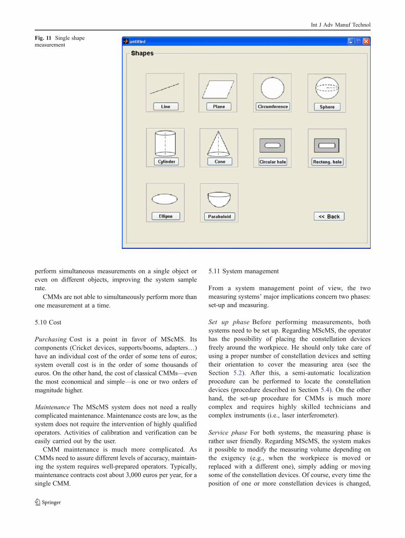
Figures 8, 9, 10, 11, and 12 show some screenshots ofMScMS user interface.
5.9 Flexibility
Kinds of measurement Considering flexibility as the abilityof performing different types of measurements, MScMSdistinguishes itself from classical CMMs. As describedabove, MScMS offers the possibility of simultaneouslyperforming different measurements (light, acoustic noise,pressure, temperature, acceleration, magnetic field, andhumidity). This kind of measurement cannot be achievedwith a classical CMM.
Geometric relations Considering flexibility as the ability ofperforming different types of geometric measurements, thesoftware functions offered by MScMS are very similar tothose offered by classical CMMs:
a. Single shape measurement (block 12 in Fig. 7). In thiscase, the measured workpiece’s feature corresponds to aprecise geometric shape (circle, plan, cylinder, etc.);
b. Relationships among different shapes. The measuredfeature arises from a relationship between two or moredifferent parts of the object’s shape, like distances,
Table 4 Comparison between the MScMS and CMMs software packages
Stage Activities Software tools
MScMS CMMs
System startup System initialization Semiautomatic procedure toopen the bluetooth connection
Semiautomatic procedure tostart up the measuring machine
System presetting Probe qualification (Manual) definition of theprobe’s geometrical features
Semiautomatic procedure forthe probe qualification
Network localization Semiautomatic procedure guided by visual instructions –Display and memorization of thelocalized network layout
Dimensionalmeasurement
Choice of themeasuring activity
Single shape measurement. IdemRelationships among different shapes(distances, intersections or angles)
Measurement target Selection of the shape (or relationship) to measure IdemMeasurement execution Measurement setting and execution IdemAudio–visual signals Warning signals Warning signals
Display of the probe’s communicationrange and network connectivity
Output display Numerical and graphical displayof the measured points
Idem
2D and 3D chartsNumerical and graphical display of the object’s featuresMeasurements system diagnostics
Int J Adv Manuf Technol
intersections, or angles between curves/surfaces (blocks13 to 15 in Fig. 7).
Concurrent measurements A significant peculiarity ofMScMS is given by the flexibility of the Cricket devices.
They are light, small, and cheap and have an embeddedprocessor to perform easy computations. For this distrib-uted computational capacity, MScMS can simultaneouslysupport two or more probes, to execute concurrent measure-ments in different parts of the network. It is so possible to
Fig. 8 The system's main menuscreenshot
Fig. 7 MScMS software architecture
Int J Adv Manuf Technol
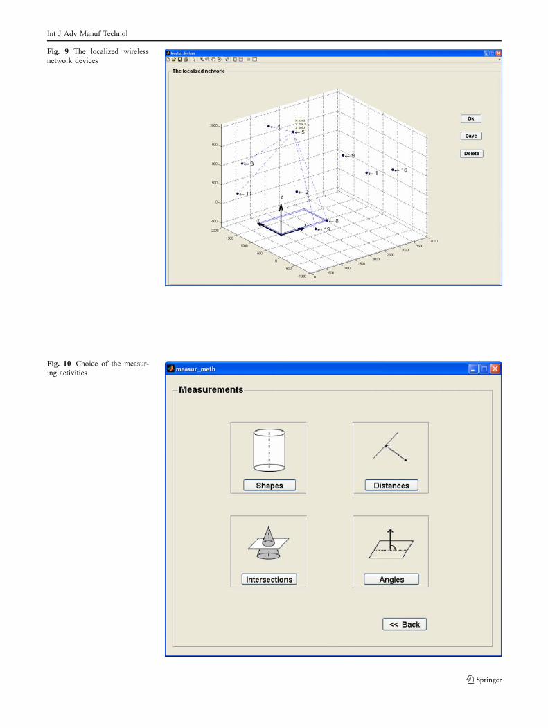
Fig. 10 Choice of the measur-ing activities
Fig. 9 The localized wirelessnetwork devices
Int J Adv Manuf Technol
perform simultaneous measurements on a single object oreven on different objects, improving the system samplerate.
CMMs are not able to simultaneously perform more thanone measurement at a time.
5.10 Cost
Purchasing Cost is a point in favor of MScMS. Itscomponents (Cricket devices, supports/booms, adapters…)have an individual cost of the order of some tens of euros;system overall cost is in the order of some thousands ofeuros. On the other hand, the cost of classical CMMs—eventhe most economical and simple—is one or two orders ofmagnitude higher.
Maintenance The MScMS system does not need a reallycomplicated maintenance. Maintenance costs are low, as thesystem does not require the intervention of highly qualifiedoperators. Activities of calibration and verification can beeasily carried out by the user.
CMM maintenance is much more complicated. AsCMMs need to assure different levels of accuracy, maintain-ing the system requires well-prepared operators. Typically,maintenance contracts cost about 3,000 euros per year, for asingle CMM.
5.11 System management
From a system management point of view, the twomeasuring systems’ major implications concern two phases:set-up and measuring.
Set up phase Before performing measurements, bothsystems need to be set up. Regarding MScMS, the operatorhas the possibility of placing the constellation devicesfreely around the workpiece. He should only take care ofusing a proper number of constellation devices and settingtheir orientation to cover the measuring area (see theSection 5.2). After this, a semi-automatic localizationprocedure can be performed to locate the constellationdevices (procedure described in Section 5.4). On the otherhand, the set-up procedure for CMMs is much morecomplex and requires highly skilled technicians andcomplex instruments (i.e., laser interferometer).
Service phase For both systems, the measuring phase israther user friendly. Regarding MScMS, the system makesit possible to modify the measuring volume depending onthe exigency (e.g., when the workpiece is moved orreplaced with a different one), simply adding or movingsome of the constellation devices. Of course, every time theposition of one or more constellation devices is changed,
Fig. 11 Single shapemeasurement
Int J Adv Manuf Technol
the set-up phase should be performed again. On thecontrary, CMMs are rigid systems in which the workingvolume size is fixed.
6 Conclusions
This paper has presented MScMS, a new system formeasuring large-size objects comparing it to CMMs, themost commonly used devices for objects dimensionalmeasurements.
MScMS and classical CMMs are similar consideringmeasurement activities; however, due to their differenttechnological features, they have many differences (forexample, system presetting, start-up, measurement execu-tion, etc.). In our opinion, they can easily coexist, aseach system has some peculiar technological features thatmake it suitable for specific uses. The lower accuracy ofMScMS makes it difficult to compete with CMMs whenit comes to measuring off-the-shelf small-size objects.However, MScMS becomes competitive in the dimen-sional evaluation of large-size workpieces, where it isoften required to move the machine to the place where
the object is. Furthermore, wireless sensor networktechnology enhances MScMS with the facility ofperforming different kinds of measurement (temperature,light, pressure, noise, etc.).
MScMS is lightweight, easily adaptable to differentworking environments, and does not require long installa-tion or start-up times. Before performing measurements,constellation devices are freely distributed around the areaof work and semi-automatically located in few minutes.System is supported by an ad hoc software created inMatLab environment to drive users through measurementsand data off-line elaborations. We reckon that the introduc-tion of this and other measuring systems based ondistributed components may have important effects onsimplifying the current measuring practices within large-scale industrial metrology.
Today, MScMS Achilles’ heel is represented by lowaccuracy, due to the use of US transceivers. Regarding thefuture, all the factors affecting system accuracy will beanalyzed in detail, to improve its performance withoutnecessitating very complex modifications to the currentCricket hardware/firmware. For example, improvementscould be obtained by modifying the current Cricket UStransducers, using more refined US ranging method or
Fig. 12 Measuring page related to the circumference shape
Int J Adv Manuf Technol
implementing proper compensation/correction techniques.In spite of the possible future improvements, it will be veryhard to close the gap between MscMS and CMMsmetrological performances, because of the US technologyintrinsic limits. Nevertheless, MScMS covers an area(large-scale metrology) in which CMMs are absolutelyexpensive and not practical; thus, it is likely to be preferredto them for some specific applications.
References
1. Balakrishnan H, Baliga R, Curtis D, Goraczko M, Miu A,Priyantha NB et al (2003) Lessons from developing and deployingthe cricket indoor location system. Tech Report, MIT
2. Bosch JA (1995) Coordinate measuring machines and systems.Edited by Marcel Dekker, New York
3. Chen M, Cheng F, Gudavalli R (2003) Precision and accuracy inan indoor localization system. Technical Report CS294-1/2,University of California, Berkeley, USA
4. Curtis MA, Farago FT (1994) Handbook of dimensional mea-surement, 3rd edn. Industrial Press, New York
5. Franceschini F, Galetto M (2007) A taxonomy of model-basedredundancy methods for CMM on-line performance verification.Int J Technol Manag 37(1/2):104–124 doi:10.1504/IJTM.2007.011806
6. Franceschini F, Galetto M, Maisano D, Mastrogiacomo L (2007)On-line diagnostics tools in the Mobile Spatial coordinateMeasuring System (MScMS), 7th ENBIS Conference, Dortmund,Germany, September 24–26, 2007
7. Franceschini F, Galetto M, Maisano D, Mastrogiacomo L (2008a)A review of localization algorithms for distributed wireless sensornetworks in manufacturing. Int J Comput Integrated Manuf (inpress). doi:10.1080/09511920601182217
8. Franceschini F, Galetto M, Maisano D, Mastrogiacomo L (2008b)Mobile spatial coordinate measuring system (MScMS)—introduc-tion to the system. Int J Prod Res (in press). doi:10.1080/00207540701881852
9. Franceschini F, Galetto M, Maisano D, Mastrogiacomo L (2008c)The problem of distributed wireless sensors positioning in themobile spatial coordinate measuring system (MScMS). In:Proceedings of the 9th Biennial ASME Conference on Engineer-ing Systems Design and Analysis ESDA08, 7–9 July 2008, Haifa,Israel
10. Franceschini F, Galetto M, Settineri L (2002) On-line diagnostictools for CMM Performance. Int J Adv Manuf Technol 19(2):125–130 doi:10.1007/s001700200005
11. Gustafsson F, Gunnarsson F (2003) Positioning using timedifference of arrival measurements. Proceedings of the IEEEInternational Conference on Acoustics, Speech, and SignalProcessing (ICASSP 2003), Hong Kong, vol 6, pp 553–556
12. Kang S, Tesar D (2004) A Novel 6-DOF measurement tool withindoor GPS for metrology and calibration of modular reconfig-urable robots. IEEE ICM International Conference on Mecha-tronics, Istanbul, Turkey
13. ISO 10360, part 2 (2001) Geometrical product specifications(GPS)—acceptance and reverification tests for coordinate mea-suring machines (CMM)
14. ISO (1993) International vocabulary of basic and general terms inmetrology, 2 edn. Geneva
15. Maisano D, Jamshidi J, Franceschini F, Maropoulos P, Mastro-giacomo L, Mileham A et al (2007) A review of two multistationlarge volume measuring instrument: MScMS and iGPS. DigitalEnterprise Technology (DET) 2007, Bath, UK, pp 418–425
16. Maisano D, Jamshidi J, Franceschini F, Maropoulos P, Mastro-giacomo L, Mileham A et al (2008) Indoor GPS: systemfunctionality and initial performance evaluation. Int J Manuf Res3(3):335–349 doi:10.1504/IJMR.2008.019214
17. Moore D, Leonard J, Rus D, Teller SS (2004) Robust distributednetwork localization with noisy range measurements. Proceedingsof SenSys 2004, Baltimore, MD, pp 50–61
18. Nagpal R, Shrobe H, Bachrach J (2003) Organizing a globalcoordinate system from local information on an ad hoc sensornetwork. Proceedings of the International Workshop on Informa-tion Processing in Sensor Networks (IPSN 2003), Palo Alto, CA
19. Patwari N, Ash J, Kyperountas S, Hero A III, Moses R, Correal N(2005) Locating the nodes—cooperative localization in wirelesssensor networks. IEEE Signal Process Mag 22(4):54–69doi:10.1109/MSP.2005.1458287
20. Phillips SD, Sawyera D, Borchardta B, Warda D, Beutelb DE(2000) A novel artifact for testing large coordinate measuringmachines. Precis Eng 25:29–34
21. Priyantha NB, Chakraborty A, Balakrishnan H (2000) The cricketlocation-support system, Proceedings of the 6th ACM MOBI-COM, Boston, MA
22. Pozzi F (2002) Comparison of 3D measurement techniques incultural heritage application: user point of view. Proceedings ofthe 1st International Symposium on 3D Data Processing Visual-ization and Transmission - IEEE Computer Society, June 19–21,Padova, Italy, pp 762–765
23. PuttockMJ (1978) Large-scale metrology. Ann CIRP 21(1):351–35624. Savvides A, Han C, Strivastava MB (2001) Dynamic fine-grained
localization in ad hoc networks of sensors. Proceedings of ACM/IEEE 7th Annual International Conference on Mobile Computingand Networking (MobiCom’01), pp 166–179
Further Reading
25. ARC Second, (2004) “Product Literature”, http://arcsecond.com/.26. Crossbow Technology (2008) http://www.xbow.com/.27. DEA (2008) http://www.dea.it/.28. Metris (2008) http://www.metris.com/large_volume_ tracking__
positioning/29. Metronor (2008) http://www.metronor.com/.
Int J Adv Manuf Technol