Embed Size (px)
Citation preview
21st International Conference on Composite Materials
Xi’an, 20-25th August 2017
MODE I INTERLAMINAR FRACTURE TOUGHNESS OF CARBON
NANOTUBE WEB-MODIFIED POLYMER COMPOSITES
Ravi Chitwan1, Andres Nistal1, Brian G. Falzon1* and Stephen C. Hawkins1, 2
1 School of Mechanical and Aerospace Engineering, Queen’s University Belfast, UK, BT9 5AH,
Email: [email protected], Web Page: http://www.qub.ac.uk
Email: [email protected], Web Page: http://www.qub.ac.uk
Email: [email protected], Web Page: http://www.qub.ac.uk
Email: [email protected], Web Page: http://www.qub.ac.uk
2Department of Materials Engineering, Monash University, Clayton, Victoria, Australia, 3800
Email: [email protected], Web Page: http://eng.monash.edu.au
Keywords: Carbon nanotube web, interlaminar fracture toughness, Toughened epoxy resin,
Multifunctional hierarchical composites.
ABSTRACT
Carbon nanotube ‘webs’ (CNTWs) are used as interlayers between marine grade (HMC/SE84LV)
and aerospace grade (IM7/977-2) carbon fibre-reinforced polymer (CFRP) composite laminates to
explore their influence on mode I interlaminar fracture toughness (ILFT). Inserting CNTW in SE84LV
laminates improves the mode I ILFT by 4% whereas inserting CNTW in 977-2 laminates reduces the
mode I ILFT by 85%. Fractography and interfacial analysis show that SE84LV resin penetrated and
adequately wetted the CNTW whereas 977-2 resin failed to penetrate and wet the CNTW which resulted
in large void formation and created a weak interlaminar region. To counter the poor penetration of 977-
2 resin, CNTW was impregnated with neat 977-2 resin prior to its insertion in the prepreg layup.
Inserting preimpregnated CNTW resulted in a 68% reduction in mode I ILFT. It is proposed that the
reduction in mode I ILFT of IM7/977-2 system interleaved with CNTW was due to the restricted resin
mobility in the CNTW region and the poor interaction between CNTW and 977-2 resin. The 977-2
remains at minimum viscosity for a shorter time than SE84LV. Remaining at low viscosity for a longer
period allows the resin to flow in the CNTW region. The weak interaction between CNTW and the 977-
2 resin is discussed in terms of the polarity of the constituent polymer molecules. 977-2 is more polar
than SE84LV thus has a very low affinity to interact with CNTW.
1 INTRODUCTION
Carbon fibre-reinforced polymer (CFRP) composites are widely used in the primary structure of the
current generation of civil aircraft, comprising for example - 50 wt. % and 53 wt. % of the airframes of
the Boeing 787 Dreamliner [1] and the Airbus A350XWB [2], respectively. Composites are preferred
over traditional aluminium alloy due to their superior specific strength and stiffness, high corrosion and
fatigue resistance [3]. However, CFRP composites have poor through-thickness fracture toughness
which makes them susceptible to delamination damage.
Various forms of carbon nanotube (CNT) assemblies (e.g. CNT forests [4], dispersed CNTs [5] and
directly grown CNTs on fibres [6]) are being studied to deliver improved electrical and thermal
management, sensing as well as improved interlaminar fracture toughness (ILFT) to composite
materials. The focus on CNTs is mainly due to their small size, low density, exceptional mechanical,
electrical and thermal properties, high aspect ratio and large specific surface area. CNTs have a distinct
electrical response to applied load [7]. Thus they are proposed as lightweight heating elements for anti-
/de-icing capability [8] and sensors for in-situ structural health monitoring (SHM) in composite
airframes. CNTs have also been used as fillers in resin to improve its electrical [9], mechanical [10] and
thermal properties [11]. However, utilisation of their properties to their full potential is limited by their
susceptibility to agglomerate within the polymer [12] and difficulty to grow the CNTs directly on
reinforcing fibres without damaging them [13].
21st International Conference on Composite Materials
Xi’an, 20-25th August 2017
A CNT ‘web’ or continuous ribbon of horizontally aligned nanotubes drawn from specially grown
vertically-aligned-CNT forests is a uniquely useful and adaptable form of CNTs. The CNT web
(CNTW) has great potential for improving the functionality of CFRP composites. However
delamination is an ‘Achilles’s heel’ of laminates so any addition of another material must at least
maintain the CFRP performance and preferably enhance it, in addition to creating the additional
functionality desired. This study investigates the effect on ‘Mode I’ interlaminar fracture toughness
(ILFT) of CFRP composites when using CNTW between the laminates.
2 EXPERIMENTAL METHODOLOGY
2.1 Materials
Composite specimens were prepared using unidirectional high modulus carbon fibre, HMC/SE84LV
prepreg, from Gurit and IM7/977-2 prepreg, from Solvay. SE84LV is a patented marine grade
thermoplastic-toughened epoxy resin system, having two bi-functional epoxy monomers [14], [15].
CYCOM 977-2 is a proprietary aerospace grade polyethersulfone-based poly-aromatic thermoplastic
toughened epoxy resin system. It has two bi-functional and one tri-functional epoxy monomers along
with 4,4-diaminodiphenyl sulfone (DDS) hardener [16], [17].
CNTWs were prepared by drawing from a high-specification CNT forest [18] and winding
continuously onto a support frame to a thickness of 10 layers. The MWCNTs have a high aspect ratio
of over 30,000. CNTs have 7 ± 3 walls with an approximate diameter of 10 nm and approximate length
of 300 μm. A single layer of CNTW has an aerial density of approximately 0.02 g/m2. The CNT forests
are grown, on silicon substrates, with a 50 nm thermal oxide and 2.5 nm e-beam deposited catalyst, by
CVD using acetylene and hydrogen (each 2.5%) in helium at 1 slm total within a 44 mm inner diameter
quartz reactor at 690 °C for 12 minutes [19].
2.2 Drawing of CNTWs
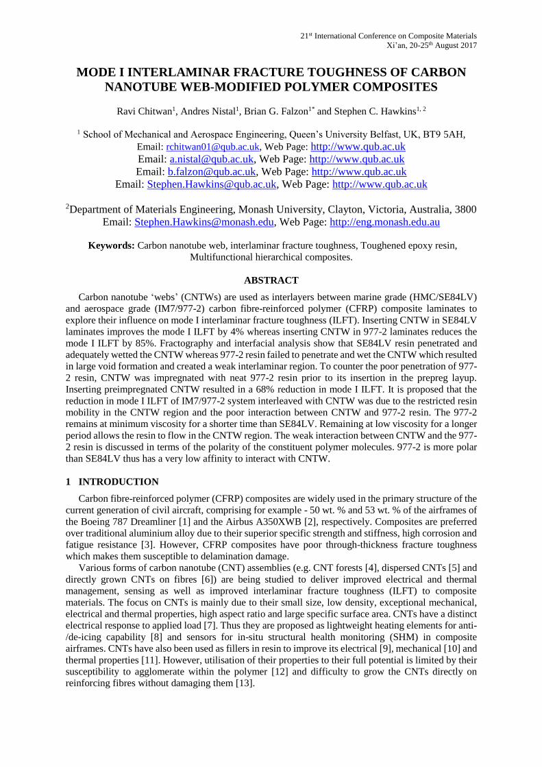
Support frames (90 mm x 90 mm with a 70 mm square opening), mounted on plastic blocks were
rotated using an electric motor. MWCNTs were drawn perpendicular to the forest and wound on the
frames, (Fig. 1a). Ten rotations of the blocks gave 10 layer of CNTWs.
(a) (b) (c)
Figure 1: (a) CNT winding, (b) CNTWs (c) scanning electron micrograph of CNTW (top view).
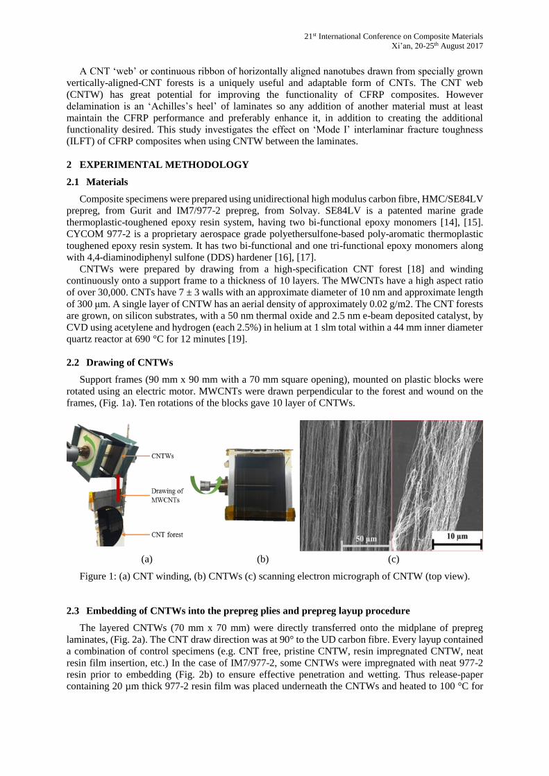
2.3 Embedding of CNTWs into the prepreg plies and prepreg layup procedure
The layered CNTWs (70 mm x 70 mm) were directly transferred onto the midplane of prepreg
laminates, (Fig. 2a). The CNT draw direction was at 90° to the UD carbon fibre. Every layup contained
a combination of control specimens (e.g. CNT free, pristine CNTW, resin impregnated CNTW, neat
resin film insertion, etc.) In the case of IM7/977-2, some CNTWs were impregnated with neat 977-2
resin prior to embedding (Fig. 2b) to ensure effective penetration and wetting. Thus release-paper
containing 20 µm thick 977-2 resin film was placed underneath the CNTWs and heated to 100 °C for
21st International Conference on Composite Materials
Xi’an, 20-25th August 2017
30 seconds which resulted in the resin fully penetrating the CNTWs. Neat resin film was inserted
separately in the composite layup forming a secondary control specimen for this case (Fig. 2a).
Figure 2: (a) Embedding of CNTWs (b) resin impregnated 10 layer CNTW.
2.4 Compression moulding and DCB specimen preparation
Once the prepreg layup was completed, the composite laminates were cured according to
manufacturers’ recommendations [16], [20]. The HMC/SE84LV layup was heated from 30 °C to 120
°C with 1 hr dwell time. The IM7/977-2 layup was heated from 30 °C to 177 °C with 3 hrs dwell time.
The ramp rate for both samples was set to 2 °C/min. After completion, the composite panels were
demoulded and 20 mm wide double cantilever beam (DCB) specimens were cut. The DCB specimens
for mode I tests were prepared in accordance with ASTM D5528 [21]. Piano hinges were attached to
the pre-cracked ends of the specimen to grip it to the mechanical testing machine.
2.5 Characterisation
DCB specimens were tested (Instron 5564, 5 kN load cell) at 2 mm/min. Microscope cameras were
placed on either sides of the specimen to track the crack tip against calibration marks and ensure the
stability of the crack-front. Applied load (P) and opening displacement (δ) were measured to calculate
the Mode I ILFT, GIC, using the modified compliance calibration (MCC) method [21]. The equations
used for this purpose are stated below [21],
𝐺𝐼𝐶 =3𝑃2𝐶
23⁄
2𝐴1𝑏ℎ × 𝐹, (1)
where C is the compliance of the DCB specimen, given as,
C = δ/P , (2)
A1 is the slope of the plot of a/b versus C1/3, where a, is the delamination (crack) length, b, is the
width of the specimen, h, is the thickness of the DCB specimen and F, is the displacement correction
factor given by,
𝐹 = 1 −3
10(
𝛿
𝑎)
2(
𝛿𝑡
𝑎2), (3)
where t, is the distance from loading block pin to centre line of the top specimen arm.
Scanning electron microscopy, (SEM, FlexSEM 1000, Hitachi) was used for fractography and
interfacial thickness and void content analysis. SEM was used in secondary electron mode. Up to 10
kV of current was supplied to the sample at a working distance of 5 mm. The spot intensity was set to
70 for low magnification and 30 for high magnification microscopy. The fracture surface was sputtered
with 5 nm thick layer of gold.
Differential scanning calorimetry, (DSC, DSC-6, PerkinElmer) was used for thermal analysis. In
dynamic scanning mode, the sample was heated from 30 °C to 350 °C at a rate of 10 °C/min whereas,
in isothermal scanning mode, the sample was heated and dwelled in accordance with the supplier’s
recommended curing profile to mimic the thermal behaviour of resins during curing process.
21st International Conference on Composite Materials
Xi’an, 20-25th August 2017
3 RESULTS AND DISCUSSION
3.1 Mode I interlaminar fracture toughness
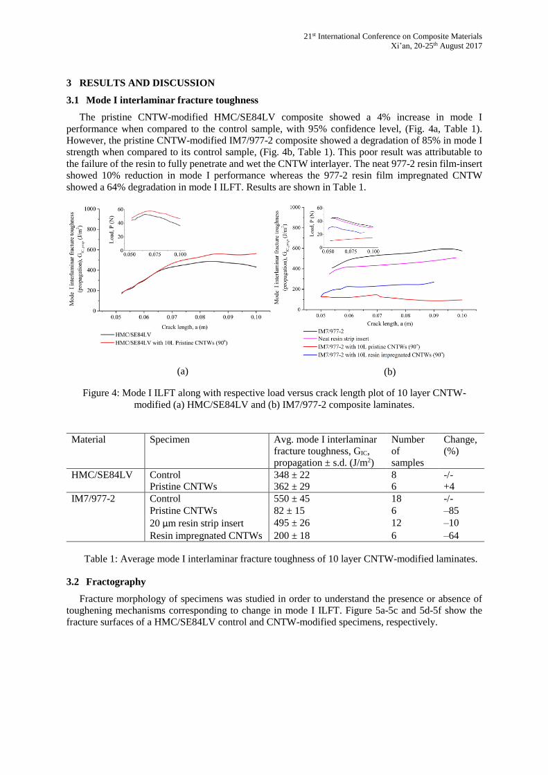
The pristine CNTW-modified HMC/SE84LV composite showed a 4% increase in mode I
performance when compared to the control sample, with 95% confidence level, (Fig. 4a, Table 1).
However, the pristine CNTW-modified IM7/977-2 composite showed a degradation of 85% in mode I
strength when compared to its control sample, (Fig. 4b, Table 1). This poor result was attributable to
the failure of the resin to fully penetrate and wet the CNTW interlayer. The neat 977-2 resin film-insert
showed 10% reduction in mode I performance whereas the 977-2 resin film impregnated CNTW
showed a 64% degradation in mode I ILFT. Results are shown in Table 1.
Figure 4: Mode I ILFT along with respective load versus crack length plot of 10 layer CNTW-
modified (a) HMC/SE84LV and (b) IM7/977-2 composite laminates.
Material Specimen Avg. mode I interlaminar
fracture toughness, GIC,
propagation ± s.d. (J/m2)
Number
of
samples
Change,
(%)
HMC/SE84LV Control 348 ± 22 8 -/-
Pristine CNTWs 362 ± 29 6 +4
IM7/977-2 Control 550 ± 45 18 -/-
Pristine CNTWs 82 ± 15 6 –85
20 µm resin strip insert 495 ± 26 12 –10
Resin impregnated CNTWs 200 ± 18 6 –64
Table 1: Average mode I interlaminar fracture toughness of 10 layer CNTW-modified laminates.
3.2 Fractography
Fracture morphology of specimens was studied in order to understand the presence or absence of
toughening mechanisms corresponding to change in mode I ILFT. Figure 5a-5c and 5d-5f show the
fracture surfaces of a HMC/SE84LV control and CNTW-modified specimens, respectively.
(a) (b)
21st International Conference on Composite Materials
Xi’an, 20-25th August 2017
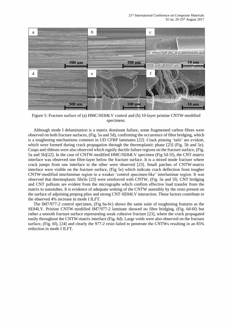
Figure 5: Fracture surface of (a) HMC/SE84LV control and (b) 10-layer pristine CNTW-modified
specimens.
Although mode I delamination is a matrix dominant failure, some fragmented carbon fibres were
observed on both fracture surfaces, (Fig. 5a and 5d), confirming the occurrence of fibre bridging, which
is a toughening mechanisms common in UD CFRP laminates [22]. Crack pinning ‘tails’ are evident,
which were formed during crack propagation through the thermoplastic phase [23] (Fig. 5b and 5e).
Cusps and ribbons were also observed which signify ductile failure regions on the fracture surface, (Fig.
5a and 5b)[22]. In the case of CNTW-modified HMC/SE84LV specimen (Fig 5d-5f), the CNT-matrix
interface was observed one fibre-layer below the fracture surface. It is a mixed mode fracture where
crack jumps from one interface to the other were observed [23]. Small patches of CNTW-matrix
interface were visible on the fracture surface, (Fig 5e) which indicate crack deflection from tougher
CNTW-modified interlaminar region to a weaker ‘control specimen-like’ interlaminar region. It was
observed that thermoplastic fibrils [23] were reinforced with CNTW, (Fig. 5e and 5f). CNT bridging
and CNT pullouts are evident from the micrographs which confirm effective load transfer from the
matrix to nanotubes. It is evidence of adequate wetting of the CNTW assembly by the resin present on
the surface of adjoining prepreg plies and strong CNT-SE84LV interaction. These factors contribute to
the observed 4% increase in mode I ILFT.
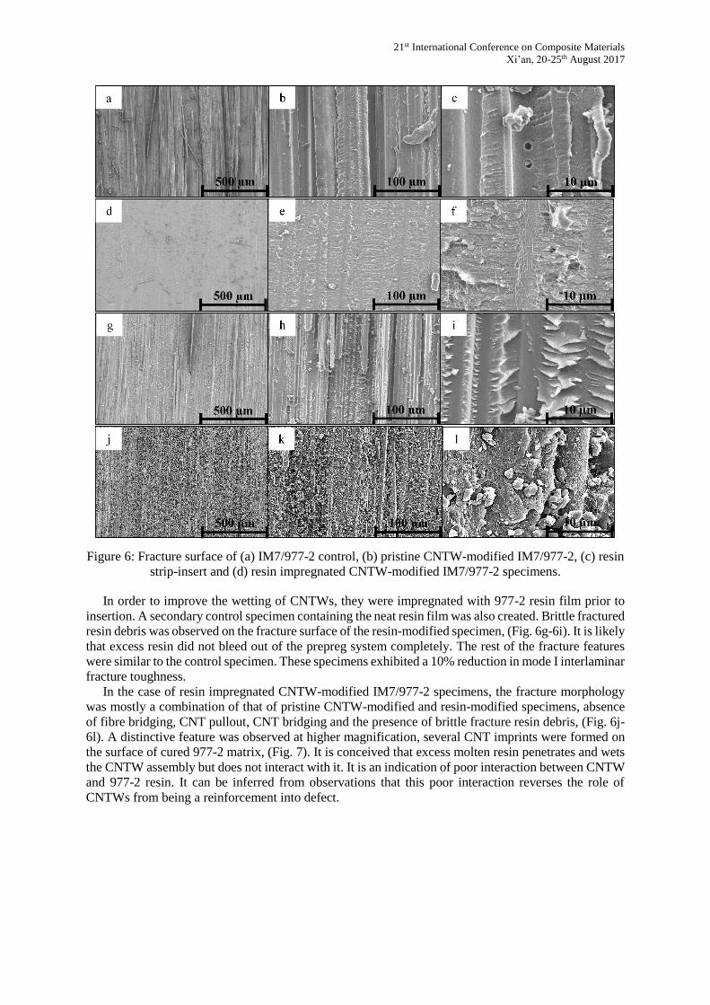
The IM7/977-2 control specimen, (Fig 6a-6c) shows the same suite of toughening features as the
SE84LV. Pristine CNTW-modified IM7/977-2 laminate showed no fibre bridging, (Fig. 6d-6f) but
rather a smooth fracture surface representing weak cohesive fracture [23], where the crack propagated
easily throughout the CNTW-matrix interface (Fig. 6d). Large voids were also observed on the fracture
surface, (Fig. 6f), [24] and clearly the 977-2 resin failed to penetrate the CNTWs resulting in an 85%
reduction in mode I ILFT.
21st International Conference on Composite Materials
Xi’an, 20-25th August 2017
Figure 6: Fracture surface of (a) IM7/977-2 control, (b) pristine CNTW-modified IM7/977-2, (c) resin
strip-insert and (d) resin impregnated CNTW-modified IM7/977-2 specimens.
In order to improve the wetting of CNTWs, they were impregnated with 977-2 resin film prior to
insertion. A secondary control specimen containing the neat resin film was also created. Brittle fractured
resin debris was observed on the fracture surface of the resin-modified specimen, (Fig. 6g-6i). It is likely
that excess resin did not bleed out of the prepreg system completely. The rest of the fracture features
were similar to the control specimen. These specimens exhibited a 10% reduction in mode I interlaminar
fracture toughness.
In the case of resin impregnated CNTW-modified IM7/977-2 specimens, the fracture morphology
was mostly a combination of that of pristine CNTW-modified and resin-modified specimens, absence
of fibre bridging, CNT pullout, CNT bridging and the presence of brittle fracture resin debris, (Fig. 6j-
6l). A distinctive feature was observed at higher magnification, several CNT imprints were formed on
the surface of cured 977-2 matrix, (Fig. 7). It is conceived that excess molten resin penetrates and wets
the CNTW assembly but does not interact with it. It is an indication of poor interaction between CNTW
and 977-2 resin. It can be inferred from observations that this poor interaction reverses the role of
CNTWs from being a reinforcement into defect.

21st International Conference on Composite Materials
Xi’an, 20-25th August 2017
Figure 7: Fracture surface of resin impregnated CNTW-modified IM7/977-2 specimen.
3.3 Analysis of CNTW-matrix interface
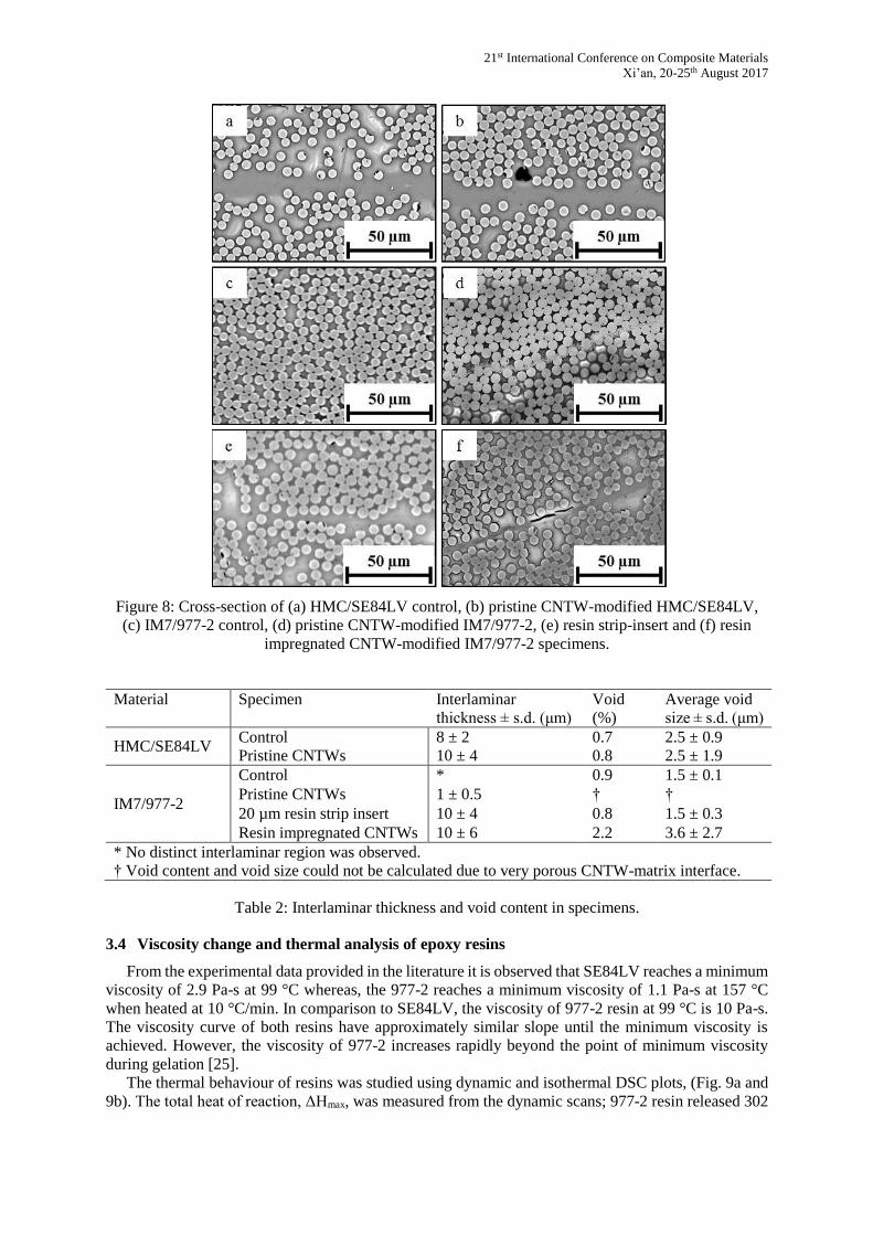
This section quantifies the change in interlaminar thickness and the increase in void content upon
inclusion of carbon nanotube webs (Fig. 8, Table 2). As shown, when 10 layers of pristine CNTWs
were inserted in HMC/SE84LV laminate, the interlaminar thickness the specimen increased by
approximately 2 μm, (Table 2, Fig. 8a and 8b). The void content increased by 0.1% but the average
void size remained the same, (Table 2). It affirms the observation that the CNTWs were adequately
wetted by SE84LV resin during cure.
On the other hand, the IM7/977-2 control specimen had no distinct interlaminar region, (Fig. 8c). A
homogenous carbon fibre-resin interface was observed. But when pristine CNTWs were inserted in
IM7/977-2 specimen, a 1 ± 0.5 µm thick, porous CNTW-matrix interface was formed, (Table 2). It is
noted that the 977-2 resin failed to penetrate into the CNTW assembly, (Fig. 8d). Furthermore, when
20 µm thick resin film was inserted in between the plies, the interlaminar thickness increased from 0 to
10 µm, (Table 2). It is confirmed from the interfacial analysis that excess resin did not bleed out of the
IM7/977-2 system during the curing process, (Fig. 8e). The ‘resin-rich’ interlaminar region resulted in
10% reduction of mode I strength. The void content and average void size in the resin-modified
specimen was similar to that of the control specimen. Furthermore, the resin impregnated CNTW-
matrix interface was seen to have similar thickness as the resin-modified specimen but the void content
in resin impregnated CNTW specimen increased to 2.2% with an average void/defect size of 3.6 ± 2.7
µm, (Fig. 8f, Table 2). This 175% increase in average defect size is correlated with the fractography
observations that suggests, poor interaction between CNTW and 977-2 matrix is the reason for the 64%
decrease in mode I strength.
21st International Conference on Composite Materials
Xi’an, 20-25th August 2017
Figure 8: Cross-section of (a) HMC/SE84LV control, (b) pristine CNTW-modified HMC/SE84LV,
(c) IM7/977-2 control, (d) pristine CNTW-modified IM7/977-2, (e) resin strip-insert and (f) resin
impregnated CNTW-modified IM7/977-2 specimens.
Material Specimen Interlaminar
thickness ± s.d. (μm)
Void
(%)
Average void
size ± s.d. (μm)
HMC/SE84LV Control 8 ± 2 0.7 2.5 ± 0.9
Pristine CNTWs 10 ± 4 0.8 2.5 ± 1.9
IM7/977-2
Control * 0.9 1.5 ± 0.1
Pristine CNTWs 1 ± 0.5 † †
20 µm resin strip insert 10 ± 4 0.8 1.5 ± 0.3
Resin impregnated CNTWs 10 ± 6 2.2 3.6 ± 2.7
* No distinct interlaminar region was observed.
† Void content and void size could not be calculated due to very porous CNTW-matrix interface.
Table 2: Interlaminar thickness and void content in specimens.
3.4 Viscosity change and thermal analysis of epoxy resins
From the experimental data provided in the literature it is observed that SE84LV reaches a minimum
viscosity of 2.9 Pa-s at 99 °C whereas, the 977-2 reaches a minimum viscosity of 1.1 Pa-s at 157 °C
when heated at 10 °C/min. In comparison to SE84LV, the viscosity of 977-2 resin at 99 °C is 10 Pa-s.
The viscosity curve of both resins have approximately similar slope until the minimum viscosity is
achieved. However, the viscosity of 977-2 increases rapidly beyond the point of minimum viscosity
during gelation [25].
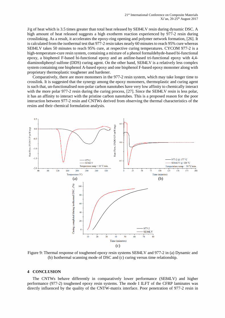
The thermal behaviour of resins was studied using dynamic and isothermal DSC plots, (Fig. 9a and
9b). The total heat of reaction, ΔHmax, was measured from the dynamic scans; 977-2 resin released 302
21st International Conference on Composite Materials
Xi’an, 20-25th August 2017
J/g of heat which is 3.5 times greater than total heat released by SE84LV resin during dynamic DSC. A
high amount of heat released suggests a high exotherm reaction experienced by 977-2 resin during
crosslinking. As a result, it accelerates the epoxy-ring opening and polymer network formation, [26]. It
is calculated from the isothermal test that 977-2 resin takes nearly 60 minutes to reach 95% cure whereas
SE84LV takes 50 minutes to reach 95% cure, at respective curing temperatures. CYCOM 977-2 is a
high-temperature-cure resin system, containing a mixture of a phenol formaldehyde-based bi-functional
epoxy, a bisphenol F-based bi-functional epoxy and an aniline-based tri-functional epoxy with 4,4-
diaminodiphenyl sulfone (DDS) curing agent. On the other hand, SE84LV is a relatively less complex
system containing one bisphenol A-based epoxy and one bisphenol F-based epoxy monomer along with
proprietary thermoplastic toughener and hardener.
Comparatively, there are more monomers in the 977-2 resin system, which may take longer time to
crosslink. It is suggested that the synergy among the epoxy monomers, thermoplastic and curing agent
is such that, un-functionalised non-polar carbon nanotubes have very low affinity to chemically interact
with the more polar 977-2 resin during the curing process, [27]. Since the SE84LV resin is less polar,
it has an affinity to interact with the pristine carbon nanotubes. This is a proposed reason for the poor
interaction between 977-2 resin and CNTWs derived from observing the thermal characteristics of the
resins and their chemical formulation analysis.
(a) (b)
(c)
Figure 9: Thermal response of toughened epoxy resin systems SE84LV and 977-2 in (a) Dynamic and
(b) Isothermal scanning mode of DSC and (c) curing versus time relationship.
4 CONCLUSION
The CNTWs behave differently in comparatively lower performance (SE84LV) and higher
performance (977-2) toughened epoxy resin systems. The mode I ILFT of the CFRP laminates was
directly influenced by the quality of the CNTW-matrix interface. Poor penetration of 977-2 resin in
21st International Conference on Composite Materials
Xi’an, 20-25th August 2017
CNTWs interlayer resulted in large void formation which weakened the CNTW-matrix interface and
degraded the mode I strength of the laminate. This poor penetration of resin and wettability of the
CNTWs may be explained in terms of the thermal and chemical characteristics of the epoxy resins. The
total heat released by 977-2 resin during curing was 3.5 times higher than that of SE84LV resin. It is
suggested that the 977-2 system experiences higher exotherm during crosslinking which accelerates the
rate of polymer network formation while the presence of highly polar 977-2 polymer molecules are
likely to adversely affect its chemical interaction with the nonpolar CNTW. It is therefore recommended
that an in-depth study of the physical and chemical interactions between CNTs and complex
thermoplastic toughened epoxy resin systems is undertaken prior to deploying CNT-based assemblies
as multifunctional fillers in aerospace composites.
ACKNOWLEDGEMENT
This work was supported by the UK Engineering and Physical Sciences Research Council (EPRSC)
grant EP/N007190/1. The corresponding author would like to acknowledge the financial support of
Bombardier and the Royal Academy of Engineering.
REFERENCES
[1] J. Fraga, “Boeing 787 from the Ground Up,” AERO Mag., pp. 17–23, 2006.
[2] R. Thevenin, “Composites in Airbus,” Glob. Invest. Forum, pp. 1–26, 2008.
[3] J. Njuguna, K. Pielichowski, and J. R. Alcock, “Epoxy-based fibre reinforced nanocomposites,”
Adv. Eng. Mater., vol. 9, no. 10, pp. 835–847, 2007.
[4] D. J. Kovach, K. H. Griess, N. Yamamoto, R. G. DeVilloria, H. G. Cebeci, and B. L. Wardle,
“Thermal and electrical transport in hybrid woven composites reinforced with aligned carbon
nanotubes,” Seattle, Washington, 2013.
[5] B. F. Jogi, “Dispersion and Performance Properties of Carbon Nanotubes (CNTs) Based
Polymer Composites: A Review,” J. Encapsulation Adsorpt. Sci., vol. 2, no. 4, pp. 69–78, 2012.
[6] S. P. Sharma and S. C. Lakkad, “Effect of CNTs growth on carbon fibers on the tensile strength
of CNTs grown carbon fiber-reinforced polymer matrix composites,” Compos. Part A Appl. Sci.
Manuf., vol. 42, no. 1, pp. 8–15, 2011.
[7] I. Kang, M. J. Schulz, J. H. Kim, V. Shanov, and D. Shi, “A carbon nanotube strain sensor for
structural health monitoring,” Smart Mater. Struct., vol. 15, no. 3, pp. 737–748, 2006.
[8] O. Gohardani, M. C. Elola, and C. Elizetxea, “Potential and prospective implementation of
carbon nanotubes on next generation aircraft and space vehicles: A review of current and
expected applications in aerospace sciences,” Progress in Aerospace Sciences, vol. 70. pp. 42–
68, 2014.
[9] J. Sandler, M. S. . Shaffer, T. Prasse, W. Bauhofer, K. Schulte, and A. . Windle, “Development
of a dispersion process for carbon nanotubes in an epoxy matrix and the resulting electrical
properties,” 1999.
[10] Z. K. Chen, J. P. Yang, Q. Q. Ni, S. Y. Fu, and Y. G. Huang, “Reinforcement of epoxy resins
with multi-walled carbon nanotubes for enhancing cryogenic mechanical properties,” Polymer
(Guildf)., vol. 50, no. 19, pp. 4753–4759, 2009.
[11] F. H. Gojny, M. H. G. Wichmann, B. Fiedler, I. A. Kinloch, W. Bauhofer, A. H. Windle, and K.
Schulte, “Evaluation and identification of electrical and thermal conduction mechanisms in
carbon nanotube/epoxy composites,” Polymer (Guildf)., vol. 47, no. 6, pp. 2036–2045, 2006.
[12] D.-L. Shi, X.-Q. Feng, Y. Y. Huang, K.-C. Hwang, and H. Gao, “The Effect of Nanotube
Waviness and Agglomeration on the Elastic Property of Carbon Nanotube-Reinforced
Composites,” J. Eng. Mater. Technol., vol. 126, no. July, p. 250, 2004.
[13] V. P. Veedu, A. Cao, X. Li, K. Ma, C. Soldano, S. Kar, P. M. Ajayan, and M. N. Ghasemi-
Nejhad, “Multifunctional composites using reinforced laminae with carbon-nanotube forests.,”
Nat. Mater., vol. 5, no. 6, pp. 457–462, 2006.
[14] Gurit (UK) Ltd., “SE84LV Material Safety Data Sheet,” Newport, UK, 2008.
[15] P. J. Spencer, G. J. Edwards, and K. V. Redrup, “Carbon Fibre-Containing Prepregs,” US
2016/0083543 A1, 2016.
[16] E. Atures and P. Ations, “Cycom 977-2 Epoxy Resin System -Technical Data Sheet,” Cytec -
21st International Conference on Composite Materials
Xi’an, 20-25th August 2017
Engineered Materials, 2012. [Online]. Available: http://www.cemselectorguide.com/
[Accessed: 10-Nov-2014].
[17] L. H. Strait, M. L. Karasek, and M. F. Amateau, “Effects of Stacking Sequence on the Impact
Resistance of Carbon Fiber Reinforced Thermoplastic Toughened Epoxy Laminates,” J.
Compos. Mater., vol. 26, no. 12, pp. 1725–1740, 1992.
[18] B. G. Falzon, S. C. Hawkins, C. P. Huynh, R. Radjef, and C. Brown, “An investigation of Mode
I and Mode II fracture toughness enhancement using aligned carbon nanotubes forests at the
crack interface,” Compos. Struct., vol. 106, pp. 65–73, Dec. 2013.
[19] C. P. Huynh and S. C. Hawkins, “Understanding the synthesis of directly spinnable carbon
nanotube forests,” Carbon N. Y., vol. 48, no. 4, pp. 1105–1115, 2010.
[20] Gurit (UK) Ltd., “SE 84LV - Low Temperature Cure Epoxy Prepreg,” General Datasheet, 2016.
[Online]. Available: www.gurit.com.
[21] ASTM Standard D5528 - 01, “Standard Test Method for Mode I Interlaminar Fracture
Toughness of Unidirectional Fibre-Reinforced Polymer Matrix Composites,” West
Conshohocken, PA, USA, 2014.
[22] E. Greenhalgh, M. Hiley, and C. Meeks, “Failure Analysis and Fractography of Polymer
Composites,” Analysis, no. March, p. 595, 2010.
[23] A. Zotti, S. Zuppolini, M. Zarrelli, and A. Borriello, “Fracture Toughening Mechanisms in
Epoxy Adhesives,” in Adhesives - Applications and Properties, A. Rudawska, Ed. InTech, 2016,
pp. 237–269.
[24] Y. Li, Q. Li, and H. Ma, “The voids formation mechanisms and their effects on the mechanical
properties of flax fiber reinforced epoxy composites,” Compos. Part A Appl. Sci. Manuf., vol.
72, pp. 40–48, 2015.
[25] M. L. Costa, E. C. Botelho, J. M. F. De Paiva, and M. C. Rezende, “Characterization of cure of
carbon/epoxy prepreg used in aerospace field,” Mater. Res., vol. 8, no. 3, pp. 317–322, 2005.
[26] K. Haman, P. Badrinarayanan, and M. R. Kessler, “Cure characterization of the ring-opening
metathesis polymerization of linseed oil-based thermosetting resins,” Polym. Int., vol. 58, no. 7,
pp. 738–744, 2009.
[27] a Carre, “Polar interactions at liquid/polymer interfaces,” J. Adhes. Sci. Technol., vol. 21, no.
10, pp. 961–981, 2007.