Embed Size (px)
Citation preview

MODEL 2480SOLARFLOW PLUS__________________________________________
DANIEL MEASUREMENT AND CONTROLHOUSTON, TEXAS
METRICMETRIC SINGLESINGLE METERMETER RUNRUN AGA-7AGA-7
APPLICATIONAPPLICATION MANUALMANUAL
HHDTHHDT EPROMEPROM 8-2480-1508-2480-15024802480 EPROMEPROM 8-2482-0048-2482-004
Part Number 3-9004-005Revision C
JULY 1999


Year 2000 Warranty
The Company represents and warrants that computer programs in any medium, software,firmware and combinations thereof (“Deliverables”) manufactured by the Company andincorporated into or supplied by the Company for use with goods manufactured by the Companywill, under normal use and care:
i) recognize and accept dates falling on or after 1 January 2000;
ii) recognize and accept the year 2000 and every succeeding fourth year as leapyears;
iii) recognize and accept 29 February in the year 2000 and every succeeding fourthyear;
iv) record, store, process, sequence, present and output calendar dates and data relatedto dates falling on or after 1 January 2000, in the same manner and with the samefunctionality as they do on or before 31 December 1999 and without errors oromissions; and
v) lose no functionality with respect to the introduction into them of dates or datarelated to dates falling on or after 1 January 2000;
provided that, in the case of any non-conforming Deliverables that are returned to the Companypromptly following discovery of the non-conformity, the Company will, at its option and cost,repair or replace such Deliverable or refund to the Purchaser the purchase price therefor. Thisshall be the Purchaser's sole and exclusive remedy for breach of the foregoing warranty.
Notwithstanding the foregoing, the Company shall not, under any circumstances whatsoever, beliable for any defects or errors caused by: materials or workmanship made, furnished or specifiedby the Purchaser; non-compliance with the Company's installation or operation requirements;failure to install any revisions and/or upgrades to the Deliverables deemed mandatory by theCompany; any modifications to Deliverables not previously authorized by the Company inwriting; the use by the Purchaser of any non-authorized spare or replacement parts in connectionwith the goods used in conjunction with the Deliverables; or the use of the Deliverables with anyhardware or software not supplied by the Company. The Purchaser shall at all times remainsolely responsible for the adequacy and accuracy of all information supplied by it. Any thirdparty content in Deliverables shall carry only the warranty extended by the original manufacturer.

THE FOREGOING CONSTITUTES THE COMPANY'S SOLE AND EXCLUSIVEWARRANTY IN RELATION TO THE PERFORMANCE OF THE DELIVERABLES AS ITRELATES TO THE CHANGE FROM YEAR 1999 TO YEAR 2000 OR THE OCCURRENCEOF LEAP YEARS THEREAFTER, AND THE PURCHASER'S EXCLUSIVE REMEDY FORBREACH THEREOF. IN NO EVENT WILL THE COMPANY BE LIABLE FOR INDIRECT,CONSEQUENTIAL, INCIDENTAL OR SPECIAL DAMAGES, INCLUDING LOSS OF USE,BUSINESS INTERRUPTION OR LOSS OF PROFITS, IRRESPECTIVE OF WHETHER THECOMPANY HAD NOTICE OF THE POSSIBILITY OF SUCH DAMAGES.
The foregoing warranty shall remain valid until the later of December 31, 2000 or one year afterthe date that the Deliverable was shipped.

METRIC SINGLE-METER RUN AGA-7 MODEL 2480 SOLARFLOW PLUS__________MAY 1997
DANIEL INDUSTRIES, INC.MODEL 2480 SOLARFLOW PLUS
METRIC SINGLE METER RUN AGA-7APPLICATION MANUAL
NOTICE
DANIEL INDUSTRIES, INC. AND DANIEL MEASUREMENT AND CONTROL ("DANIEL")SHALL NOT BE LIABLE FOR TECHNICAL OR EDITORIAL ERRORS IN THIS MANUALOR OMISSIONS FROM THIS MANUAL.DANIEL MAKES NO WARRANTIES, EXPRESSOR IMPLIED, INCLUDING THE IMPLIED WARRANTIES OF MERCHANTABILITYAND FITNESS FOR A PARTICULAR PURPOSE WITH RESPECT TO THIS MANUALAND, IN NO EVENT, SHALL DANIEL BE LIABLE FOR ANY SPECIAL ORCONSEQUENTIAL DAMAGES INCLUDING, BUT NOT LIMITED TO, LOSS OFPRODUCTION, LOSS OF PROFITS, ETC.
PRODUCT NAMES USED HEREIN ARE FOR MANUFACTURER OR SUPPLIERIDENTIFICATION ONLY AND MAY BE TRADEMARKS/REGISTERED TRADEMARKS OFTHESE COMPANIES.
COPYRIGHT © 1997BY DANIEL MEASUREMENT AND CONTROL
HOUSTON, TEXAS, U.S.A.
All rights reserved. No part of this work may be reproduced orcopied in any form or by any means - graphic, electronic ormechanical - without first receiving the written permission ofDaniel Measurement and Control, Houston, Texas, U.S.A.
PREFACE i

__________METRIC SINGLE-METER RUN AGA-7 MODEL 2480 SOLARFLOW PLUSMAY 1997
WARRANTY
Daniel Measurement and Control ("Daniel") warrants all equipment manufactured by it to be freefrom defects in workmanship and material, provided that such equipment was properly selectedfor the service intended, properly installed, and not misused. Equipment which is returned,transportation prepaid to Daniel within twelve (12) months of the date of shipment (eighteen (18)months from date of shipment for destinations outside of the United States), which is found afterinspection by Daniel to be defective in workmanship or material, will be repaired or replaced atDaniel’s sole option, free of charge, and return-shipped at lowest cost transportation. Alltransportation charges and export fees will be billed to the customer. Warranties on devicespurchased from third party manufacturers not bearing a Daniel label shall have the warrantyprovided by the third party manufacturer.
Extended warranty -Models 2470, 2480 and 2500 are warranted for a maximum of twenty-four(24) months. The Danalyzer valves are warranted for the life of the instrument and the columnsfor five years.
The warranties specified herein are in lieu of any and all other warranties, express or implied,including any warranty of merchantability or fitness for a particular purpose.
Daniel shall be liable only for loss or damage directly caused by its sole negligence. Daniel’sliability for any loss or damage arising out of, connected with, or resulting from any breachhereof shall in no case exceed the price allocable to the equipment or unit thereof which givesrise to the claim. Daniel’s liability shall terminate one year after the delivery of the equipmentexcept for overseas deliveries and extended warranty products as noted above.
In no event, whether as a result of breach of warranty or alleged negligence, shall Daniel beliable for special or consequential damages, including, but not limited to, loss of profits orrevenue; loss of equipment or any associated equipment; cost of capital; cost of substituteequipment, facilities or services; downtime costs; or claims of customers of the purchaser forsuch damages.
PREFACEii

METRIC SINGLE-METER RUN AGA-7 MODEL 2480 SOLARFLOW PLUS__________MAY 1997
TABLE OF CONTENTS
Section Page
SECTION 1
1.0 INTRODUCTION . . . . . . . . . . . . . . . . . . . . . . . . . . . . . . . . . . . . . . . . . . . 1-11.1 SCOPE OF THIS MANUAL . . . . . . . . . . . . . . . . . . . . . . . . . . . . . . 1-11.2 AGA-7 SINGLE TURBINE/PD "AGA-7 2480 MET"
APPLICATION . . . . . . . . . . . . . . . . . . . . . . . . . . . . . . . . . . . . . . . . 1-2
SECTION 2
2.0 AGA-7 SINGLE TURBINE/PD "AGA-7 2480 MET"CALCULATION MODULE . . . . . . . . . . . . . . . . . . . . . . . . . . . . . . . . . . . . 2-1
SECTION 3
3.0 FIELD WIRING CONNECTIONS . . . . . . . . . . . . . . . . . . . . . . . . . . . . . . . 3-13.1 INPUT CONNECTIONS . . . . . . . . . . . . . . . . . . . . . . . . . . . . . . . . 3-1
3.1.1 Analog Input Connections. . . . . . . . . . . . . . . . . . . . . . . . . . . . 3-13.1.2 PD/Turbine Meter Input Connections. . . . . . . . . . . . . . . . . . . . . 3-23.1.3 Status Input Connections. . . . . . . . . . . . . . . . . . . . . . . . . . . . . 3-2
3.2 OUTPUT SIGNAL CONNECTIONS . . . . . . . . . . . . . . . . . . . . . . . . 3-43.2.1 TTL Level Signal Output. . . . . . . . . . . . . . . . . . . . . . . . . . . . . 3-4
SECTION 4
4.0 SETUP LOCATION MENU . . . . . . . . . . . . . . . . . . . . . . . . . . . . . . . . . . . . 4-1
SECTION 5
5.0 SECURITY CODE LIST . . . . . . . . . . . . . . . . . . . . . . . . . . . . . . . . . . . . . . 5-1
TABLE OF CONTENTS iii
__________METRIC SINGLE-METER RUN AGA-7 MODEL 2480 SOLARFLOW PLUSMAY 1997
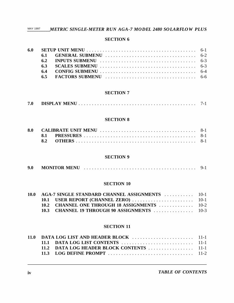
SECTION 6
6.0 SETUP UNIT MENU . . . . . . . . . . . . . . . . . . . . . . . . . . . . . . . . . . . . . . . . . 6-16.1 GENERAL SUBMENU . . . . . . . . . . . . . . . . . . . . . . . . . . . . . . . . . . 6-26.2 INPUTS SUBMENU . . . . . . . . . . . . . . . . . . . . . . . . . . . . . . . . . . . . 6-36.3 SCALES SUBMENU . . . . . . . . . . . . . . . . . . . . . . . . . . . . . . . . . . . . 6-36.4 CONFIG SUBMENU . . . . . . . . . . . . . . . . . . . . . . . . . . . . . . . . . . . . 6-46.5 FACTORS SUBMENU . . . . . . . . . . . . . . . . . . . . . . . . . . . . . . . . . . 6-6
SECTION 7
7.0 DISPLAY MENU . . . . . . . . . . . . . . . . . . . . . . . . . . . . . . . . . . . . . . . . . . . . 7-1
SECTION 8
8.0 CALIBRATE UNIT MENU . . . . . . . . . . . . . . . . . . . . . . . . . . . . . . . . . . . . 8-18.1 PRESSURES. . . . . . . . . . . . . . . . . . . . . . . . . . . . . . . . . . . . . . . . . . 8-18.2 OTHERS . . . . . . . . . . . . . . . . . . . . . . . . . . . . . . . . . . . . . . . . . . . . . 8-1
SECTION 9
9.0 MONITOR MENU . . . . . . . . . . . . . . . . . . . . . . . . . . . . . . . . . . . . . . . . . . 9-1
SECTION 10
10.0 AGA-7 SINGLE STANDARD CHANNEL ASSIGNMENTS . . . . . . . . . . . 10-110.1 USER REPORT (CHANNEL ZERO) . . . . . . . . . . . . . . . . . . . . . . . 10-110.2 CHANNEL ONE THROUGH 18 ASSIGNMENTS . . . . . . . . . . . . . 10-210.3 CHANNEL 19 THROUGH 90 ASSIGNMENTS . . . . . . . . . . . . . . . 10-3
SECTION 11
11.0 DATA LOG LIST AND HEADER BLOCK . . . . . . . . . . . . . . . . . . . . . . . 11-111.1 DATA LOG LIST CONTENTS . . . . . . . . . . . . . . . . . . . . . . . . . . . 11-111.2 DATA LOG HEADER BLOCK CONTENTS . . . . . . . . . . . . . . . . . 11-111.3 LOG DEFINE PROMPT . . . . . . . . . . . . . . . . . . . . . . . . . . . . . . . . 11-2
TABLE OF CONTENTSiv
METRIC SINGLE-METER RUN AGA-7 MODEL 2480 SOLARFLOW PLUS__________MAY 1997
11.4 CHANNEL 19 AUXILIARY INPUT . . . . . . . . . . . . . . . . . . . . . . . . 11-2
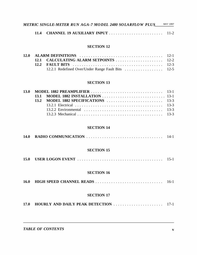
SECTION 12
12.0 ALARM DEFINITIONS . . . . . . . . . . . . . . . . . . . . . . . . . . . . . . . . . . . . . 12-112.1 CALCULATING ALARM SETPOINTS . . . . . . . . . . . . . . . . . . . . . 12-212.2 FAULT BITS . . . . . . . . . . . . . . . . . . . . . . . . . . . . . . . . . . . . . . . .12-3
12.2.1 Redefined Over/Under Range Fault Bits. . . . . . . . . . . . . . . . . 12-5
SECTION 13
13.0 MODEL 1882 PREAMPLIFIER . . . . . . . . . . . . . . . . . . . . . . . . . . . . . . . . 13-113.1 MODEL 1882 INSTALLATION . . . . . . . . . . . . . . . . . . . . . . . . . . . .13-113.2 MODEL 1882 SPECIFICATIONS . . . . . . . . . . . . . . . . . . . . . . . . . 13-3
13.2.1 Electrical . . . . . . . . . . . . . . . . . . . . . . . . . . . . . . . . . . . . . . . 13-313.2.2 Environmental . . . . . . . . . . . . . . . . . . . . . . . . . . . . . . . . . . . 13-313.2.3 Mechanical. . . . . . . . . . . . . . . . . . . . . . . . . . . . . . . . . . . . . . 13-3
SECTION 14
14.0 RADIO COMMUNICATION . . . . . . . . . . . . . . . . . . . . . . . . . . . . . . . . . . 14-1
SECTION 15
15.0 USER LOGON EVENT . . . . . . . . . . . . . . . . . . . . . . . . . . . . . . . . . . . . . . 15-1
SECTION 16
16.0 HIGH SPEED CHANNEL READS . . . . . . . . . . . . . . . . . . . . . . . . . . . . . . 16-1
SECTION 17
17.0 HOURLY AND DAILY PEAK DETECTION . . . . . . . . . . . . . . . . . . . . . . 17-1
TABLE OF CONTENTS v

__________METRIC SINGLE-METER RUN AGA-7 MODEL 2480 SOLARFLOW PLUSMAY 1997
LIST OF ILLUSTRATIONS
Figure 3.1 Terminal Board Connections. . . . . . . . . . . . . . . . . . . . . . . . . . . . . . . . 3-3
Figure 13.1 Location of Capacitors C21 and C22. . . . . . . . . . . . . . . . . . . . . . . . . 13-2
TABLE OF CONTENTSvi
METRIC SINGLE-METER RUN AGA-7 MODEL 2480 SOLARFLOW PLUS__________MAY 1997
SECTION 1
1.0 INTRODUCTION
1.1 SCOPE OF THIS MANUAL
A SolarFlow Plus unit delivered from the factory is fitted with a erasable, programmable,read-only memory (EPROM) configured for the application for which the SolarFlow Plus isintended. The Hand Held Data Terminal (HHDT) provided with SolarFlow Plus is compatiblewith all Model 2480 standard applications. This manual provides specific information on aModel 2480 SolarFlow system configured for the Model 2480, metric single-meter run AGA-7application. Basic reference information on the Model 2480 SolarFlow Plus system is providedin the System Reference Manual (Daniel Part Number 3-9000-497). The System ReferenceManual includes sections on system hardware, software, installation, and operating proceduresfor both the SolarFlow Plus computer and the HHDT. The System Reference manual, togetherwith this application manual provides a complete information package for a specific installationof the Model 2480 SolarFlow Plus system. Daniel Model 1882 Preamplifier may be of particularinterest to AGA-7 users. Daniel Model 1882, mounted separately from the Model 2480, is a lowpower preamplifier that enables a higher pulse input (up to five KHz). Refer to section 13 foradditional information. This manual provides references to the System Reference Manualwhenever more detailed information is provided in that manual.
This manual includes sections on:
· Calculation modules for the metric AGA-7 single-meter run application
· Field wiring connections for applicable inputs and outputs
· SETUP LOCATION menu parameters for the Hand Held Data Terminal (HHDT)
· SETUP UNIT menu parameters for the HHDT
· DISPLAY, CALIBRATE UNIT, and MONITOR menus for the HHDT
· Default user report listing
· Channel assignments for the unit
· Default data log list
SECTION 1 1-1

__________METRIC SINGLE-METER RUN AGA-7 MODEL 2480 SOLARFLOW PLUSMAY 1997
· Default security codes
· Default alarm list
1.2 AGA-7 SINGLE TURBINE/PD "AGA-7 2480 MET" APPLICATION
The AGA-7 standard applies to situations where gas volume must be corrected for pressure(Boyle’s Law) and temperature (Charles’ Law). It also includes factors to correct for atemperature base change, a pressure base change, and the non-ideal variation in volume(supercompressibility).
In an AGA-7 application, a volume measuring device (usually a meter of the positivedisplacement type) produces a series of pulses, a certain number of which represents an"uncorrected" volume of gas (Vu). This uncorrected volume is used to calculate corrected (orstandard) volume using the equation provided in section 2.
INTRODUCTION1-2
METRIC SINGLE-METER RUN AGA-7 MODEL 2480 SOLARFLOW PLUS__________MAY 1997
SECTION 2
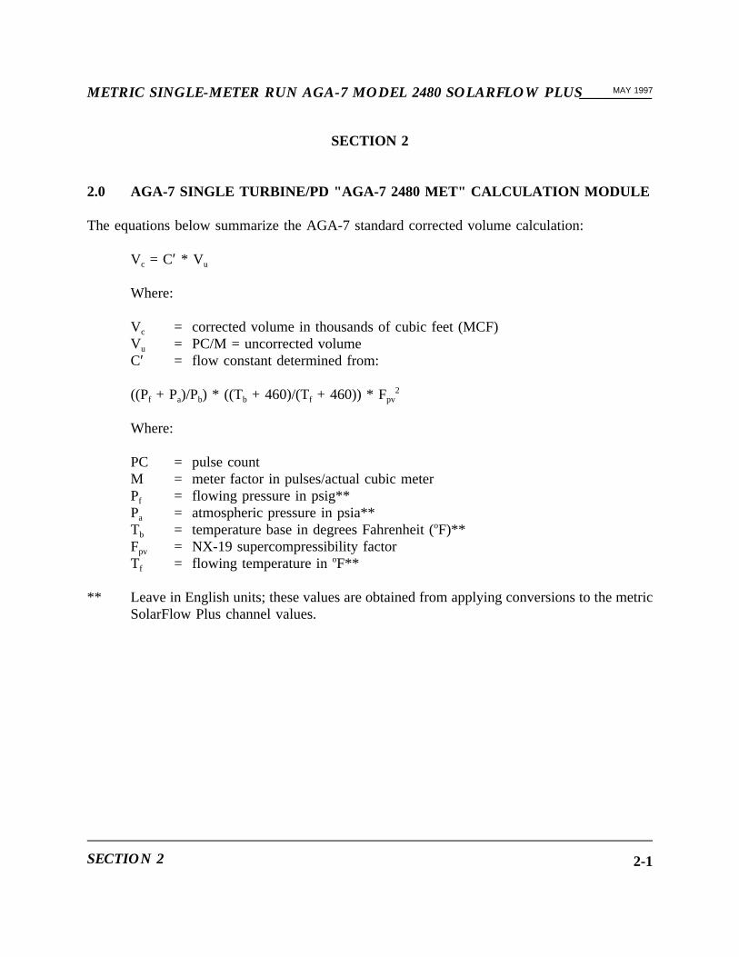
2.0 AGA-7 SINGLE TURBINE/PD "AGA-7 2480 MET" CALCULATION MODULE
The equations below summarize the AGA-7 standard corrected volume calculation:
Vc = C′ * V u
Where:
Vc = corrected volume in thousands of cubic feet (MCF)Vu = PC/M = uncorrected volumeC′ = flow constant determined from:
((Pf + Pa)/Pb) * ((Tb + 460)/(Tf + 460)) * Fpv2
Where:
PC = pulse countM = meter factor in pulses/actual cubic meterPf = flowing pressure in psig**Pa = atmospheric pressure in psia**Tb = temperature base in degrees Fahrenheit (oF)**Fpv = NX-19 supercompressibility factorTf = flowing temperature inoF**
** Leave in English units; these values are obtained from applying conversions to the metricSolarFlow Plus channel values.
SECTION 2 2-1
__________METRIC SINGLE-METER RUN AGA-7 MODEL 2480 SOLARFLOW PLUSMAY 1997
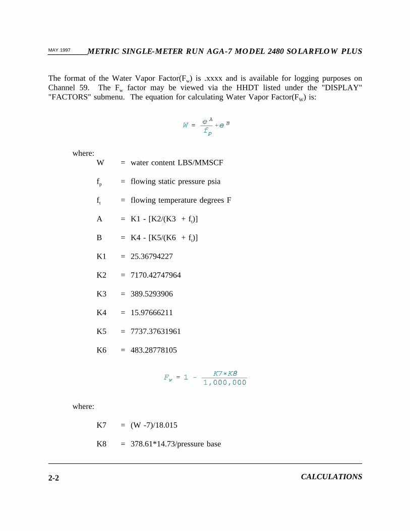
The format of the Water Vapor Factor(Fw) is .xxxx and is available for logging purposes onChannel 59. The Fw factor may be viewed via the HHDT listed under the "DISPLAY""FACTORS" submenu. The equation for calculating Water Vapor Factor(FW) is:
where:W = water content LBS/MMSCF
fp = flowing static pressure psia
ft = flowing temperature degrees F
A = K1 - [K2/(K3 + f t)]
B = K4 - [K5/(K6 + ft)]
K1 = 25.36794227
K2 = 7170.42747964
K3 = 389.5293906
K4 = 15.97666211
K5 = 7737.37631961
K6 = 483.28778105
where:
K7 = (W -7)/18.015
K8 = 378.61*14.73/pressure base
CALCULATIONS2-2

METRIC SINGLE-METER RUN AGA-7 MODEL 2480 SOLARFLOW PLUS__________MAY 1997
During normal operations, calculations are performed continuously. Each complete set ofcalculations is called a calculation cycle. The diagram below illustrates a series of calculationcycles.
...|------ N-1 ------|----- N -----|----- N+1 -----|...Time -->
The time required to complete a calculation cycle depends on processor speed and the extent ofdata communication with the calculation module.
At the beginning of calculation cycle N, the following data pertaining to the previous calculationcycle (N-1) is available:
1. Average static pressure and temperature for each meter run based on 1/2-second samples.
2. A non-zero pulse count.
During calculation cycle N, SolarFlow Plus calculates a flow constant based on static pressureand temperature. If a no-flow condition exists prior to calculation cycle N-1, SolarFlow Pluscalculates the flow constant based on current (not average) pressure and temperature values.When flow is established, corrected volume is calculated by applying the flow constant and meterfactor from calculation cycle N-1. The averages and the pulse count accumulated duringcalculation cycle N are available for calculations during cycle N+1.
Flow rate is determined from a ring buffer that maintains a record of the pulse count for each1/2 second during the previous 60 seconds. A variable time window of 5 to 60 seconds providesfor a minimum pulse count of 59. Flow rate calculations are based on the number of pulses, theelapsed time, and the most recent flow constant. During periods when no pulses occur,SolarFlow Plus continues to calculate flow rate at 5-second intervals. A zero flow rate resultswhenever less than 60 pulses are received during any 60-second period.
SECTION 2 2-3

__________METRIC SINGLE-METER RUN AGA-7 MODEL 2480 SOLARFLOW PLUSMAY 1997
This page intentionally left blank.
CALCULATIONS2-4
METRIC SINGLE-METER RUN AGA-7 MODEL 2480 SOLARFLOW PLUS__________MAY 1997
SECTION 3
3.0 FIELD WIRING CONNECTIONS
3.1 INPUT CONNECTIONS
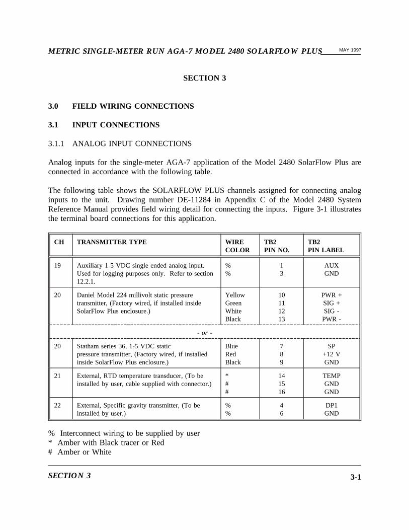
3.1.1 ANALOG INPUT CONNECTIONS
Analog inputs for the single-meter AGA-7 application of the Model 2480 SolarFlow Plus areconnected in accordance with the following table.
The following table shows the SOLARFLOW PLUS channels assigned for connecting analoginputs to the unit. Drawing number DE-11284 in Appendix C of the Model 2480 SystemReference Manual provides field wiring detail for connecting the inputs. Figure 3-1 illustratesthe terminal board connections for this application.
CH TRANSMITTER TYPE WIRECOLOR
TB2PIN NO.
TB2PIN LABEL
19 Auxiliary 1-5 VDC single ended analog input.Used for logging purposes only. Refer to section12.2.1.
%%
13
AUXGND
20 Daniel Model 224 millivolt static pressuretransmitter, (Factory wired, if installed insideSolarFlow Plus enclosure.)
YellowGreenWhiteBlack
10111213
PWR +SIG +SIG -PWR -
- or -
20 Statham series 36, 1-5 VDC staticpressure transmitter, (Factory wired, if installedinside SolarFlow Plus enclosure.)
BlueRedBlack
789
SP+12 VGND
21 External, RTD temperature transducer, (To beinstalled by user, cable supplied with connector.)
*##
141516
TEMPGNDGND
22 External, Specific gravity transmitter, (To beinstalled by user.)
%%
46
DP1GND
% Interconnect wiring to be supplied by user* Amber with Black tracer or Red# Amber or White
SECTION 3 3-1

__________METRIC SINGLE-METER RUN AGA-7 MODEL 2480 SOLARFLOW PLUSMAY 1997
NOTE: If the specific gravity input is FIXED rather than LIVE, digitalchannel No.1 should be held at ground level (0 volts) by installinga jumper wire between pins 1 and 2 of TB1 on the rear terminationboard of the Model 2480 SolarFlow Plus. The value for thespecific gravity input is entered in the CONFIG submenu of theSETUP UNIT menu by keying in the desired value for theparameter, FIXED SG.
3.1.2 PD/TURBINE METER INPUT CONNECTIONS
INPUT DESCRIPTION WIRECOLOR
TB1 PINNO.
TB1 PINLABEL
PD/Turbine Meter, maximumfrequency of 50 Hz.*
%%
1718
GNDPD
% Interconnect wiring to be supplied by user.
* For pulse inputs up to a maximum frequency of 5 KHz, see section 13 for informationon the Model 1882.
3.1.3 STATUS INPUT CONNECTIONS
This application supports one status input that is activated by means of a dry contact closurebetween the status input channel and common. When TB1 pins 1 and 2 are connected together(shorted), a FIXED specific gravity will be used. When pins 1 and 2 are not connected(open),a live specific gravity will be used. The following details the pin-out arrangement for the statusinput.
CHNO.
DESCRIPTION LABEL TB1 PINNO.
TB1 PINLABEL
SIGNALTYPE
1 Fixed SG option FIXED 21
IN 1GND
Status inCommon
FIELD WIRING CONNECTIONS3-2

METRIC SINGLE-METER RUN AGA-7 MODEL 2480 SOLARFLOW PLUS__________MAY 1997
Figure 3-1. Terminal Board Connections
SECTION 3 3-3

__________METRIC SINGLE-METER RUN AGA-7 MODEL 2480 SOLARFLOW PLUSMAY 1997
3.2 OUTPUT SIGNAL CONNECTIONS
NOTE: All output signals from a SolarFlow Plus unit installed in ahazardous location must be isolated by means of intrinsic safetybarriers.
This application has one TTL level output that provides a digital output for corrected stationvolume on channel 5. The volume per pulse and the pulse period of the output may be changedusing the HHDT. Prompts for changing the volume per pulse (VPP1) and pulse period (PP1) areincluded in the discussion of the CONFIG submenu of the SETUP UNIT menu.
3.2.1 TTL LEVEL SIGNAL OUTPUT
TTL level output for channel 5 is available at the termination board pin numbers shown in thefollowing table.
CHNO.
SIGNALDESCRIPTION
LABEL TB1PIN NO.
TB1LABEL
SIGNALTYPE
5 Volume pulse output 1 VP1 109
OUT1GND
TTL OutputCommon
FIELD WIRING CONNECTIONS3-4
METRIC SINGLE-METER RUN AGA-7 MODEL 2480 SOLARFLOW PLUS__________MAY 1997
SECTION 4
4.0 SETUP LOCATION MENU
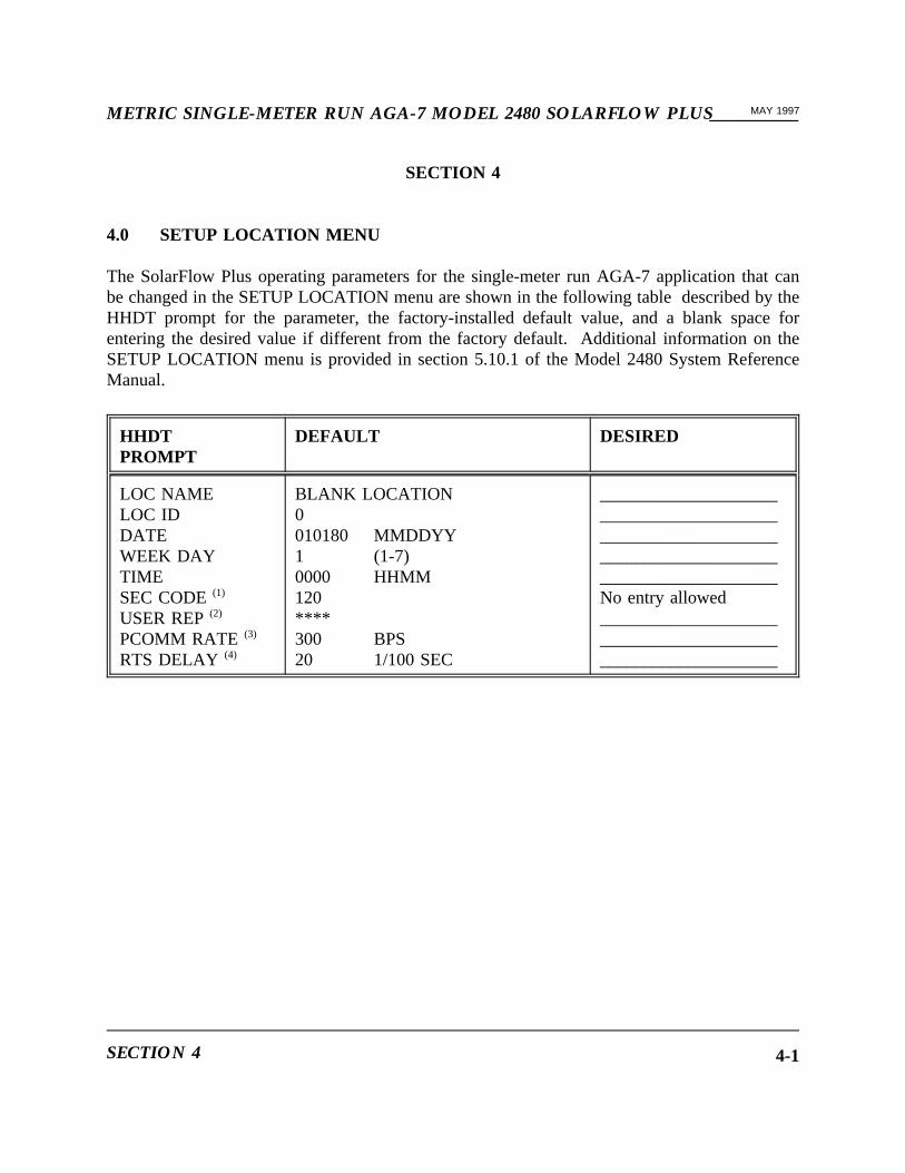
The SolarFlow Plus operating parameters for the single-meter run AGA-7 application that canbe changed in the SETUP LOCATION menu are shown in the following table described by theHHDT prompt for the parameter, the factory-installed default value, and a blank space forentering the desired value if different from the factory default. Additional information on theSETUP LOCATION menu is provided in section 5.10.1 of the Model 2480 System ReferenceManual.
HHDTPROMPT
DEFAULT DESIRED
LOC NAMELOC IDDATEWEEK DAYTIMESEC CODE(1)
USER REP(2)
PCOMM RATE (3)
RTS DELAY (4)
BLANK LOCATION0010180 MMDDYY1 (1-7)0000 HHMM120****300 BPS20 1/100 SEC
____________________________________________________________________________________________________No entry allowed____________________________________________________________
SECTION 4 4-1
__________METRIC SINGLE-METER RUN AGA-7 MODEL 2480 SOLARFLOW PLUSMAY 1997
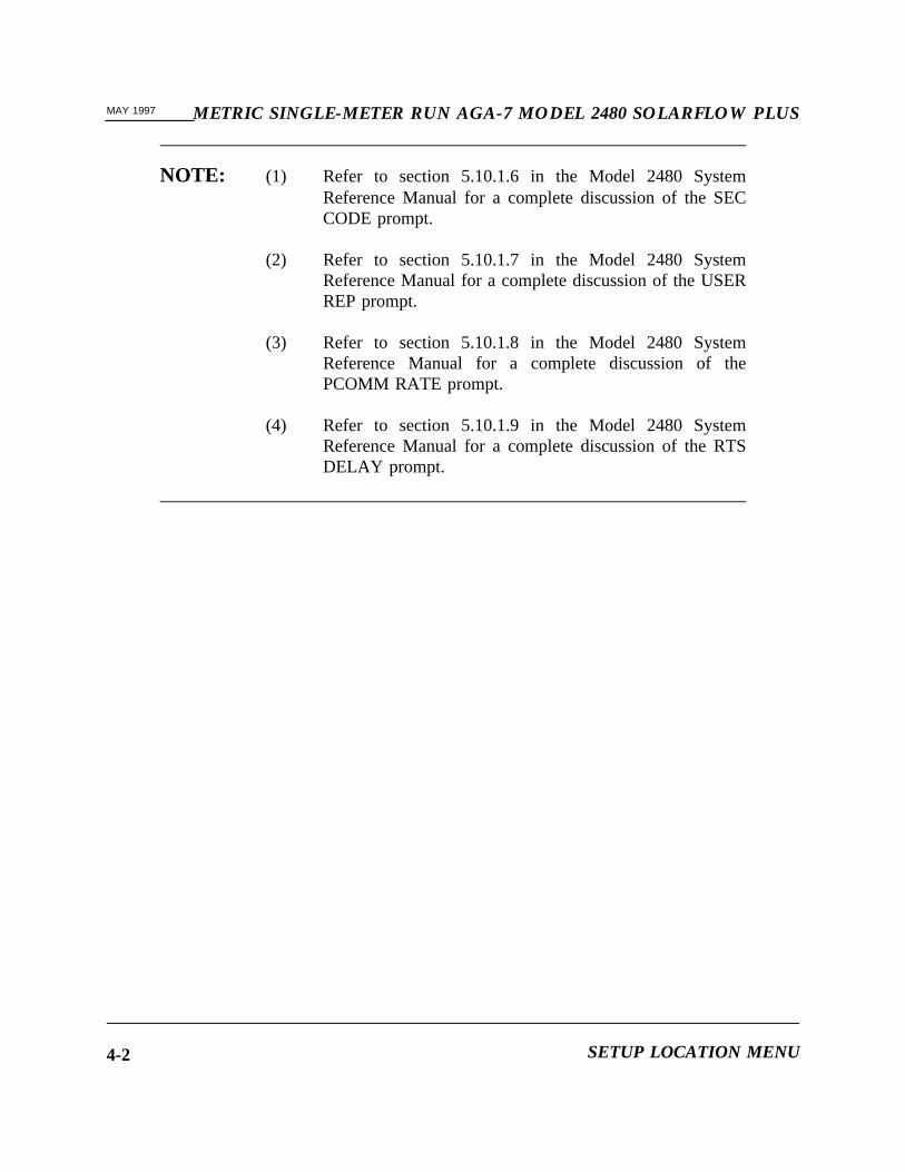
NOTE: (1) Refer to section 5.10.1.6 in the Model 2480 SystemReference Manual for a complete discussion of the SECCODE prompt.
(2) Refer to section 5.10.1.7 in the Model 2480 SystemReference Manual for a complete discussion of the USERREP prompt.
(3) Refer to section 5.10.1.8 in the Model 2480 SystemReference Manual for a complete discussion of thePCOMM RATE prompt.
(4) Refer to section 5.10.1.9 in the Model 2480 SystemReference Manual for a complete discussion of the RTSDELAY prompt.
SETUP LOCATION MENU4-2

METRIC SINGLE-METER RUN AGA-7 MODEL 2480 SOLARFLOW PLUS__________MAY 1997
SECTION 5
5.0 SECURITY CODE LIST
The default security code list for this application is: 120, 101, 111, 121, 131, 141, 102, 112, 122,132, 142.
SECTION 5 5-1

__________METRIC SINGLE-METER RUN AGA-7 MODEL 2480 SOLARFLOW PLUSMAY 1997
This page intentionally left blank.
SECURITY CODE LIST5-2

METRIC SINGLE-METER RUN AGA-7 MODEL 2480 SOLARFLOW PLUS__________MAY 1997
SECTION 6
6.0 SETUP UNIT MENU
The parameters for the single-meter AGA-7 (AGA-7 2480 MET) application of SolarFlow Plusthat can be changed in the five submenus of the SETUP UNIT menu using the HHDT aretabulated as follows. The parameters are tabulated by the HHDT prompt for the parameter, thefactory-installed default, and a blank space for entering the desired value if different from thefactory default.
SECTION 6 6-1

__________METRIC SINGLE-METER RUN AGA-7 MODEL 2480 SOLARFLOW PLUSMAY 1997
6.1 GENERAL SUBMENU
The following parameters can be changed in the GENERAL submenu of the SETUP UNIT menuof the HHDT.
HHDTPROMPT
DEFAULT DESIRED
UNIT NAMEUNIT IDCONTRCT HRLOG INTRVLLOG DEFINE (1)
RESET CMOD(2)
BLANK UNITBLANK ID7 (0-23)1 HR
OFF
__________________________________________________________________________________________________________________
NOTE: (1) Before making changes in the LOG DEFINE Submenu,collect all data logs in SolarFlow Plus memory. Any timea change is made in the LOG DEFINE menu, all data logsin SolarFlow Plus memory are automatically erased andcannot be recovered. Refer to section 11.3 for adescription of the LOG DEFINE prompt.
(2) The RESET CMOD (Reset Calculations Module) promptperforms no function in Model 2480 SolarFlow Plus. It isused in Models 2460 and 2470 to change to anotherapplication when necessary. The calculations module inModel 2480 is established upon initial startup. Refer tosection 5.10.2 in the System Reference Manual.
SETUP UNIT MENU6-2

METRIC SINGLE-METER RUN AGA-7 MODEL 2480 SOLARFLOW PLUS__________MAY 1997
6.2 INPUTS SUBMENU
The INPUTS submenu of the SETUP UNIT menu of the HHDT provides for switching betweenLIVE and FIXED values of the analog inputs shown as follows. Refer to section 5.10.2.2 in theModel 2480 System Reference Manual for additional information.
HHDT PROMPT DEFAULT
METR PRESMETR TEMPLIVE SG
XXXXX KPaXXXXX DEGCXXXXX
6.3 SCALES SUBMENU
The high- and low-scale setpoints for the analog inputs shown in the following table can bemodified in the SCALES submenu of the SETUP UNIT menu of the HHDT. Refer to section5.10.2.3 in the Model 2480 System Reference Manual for additional information.
HHDTPROMPT
DEFAULT DESIRED
M PRES /LOM PRES /HIM TEMP /LOM TEMP /HILIVE SG/LOLIVE SG/HI
06900
-18660.60.8
KPaKPaDEGCDEGC
__________________________________________________________________________________________________________________
SECTION 6 6-3
__________METRIC SINGLE-METER RUN AGA-7 MODEL 2480 SOLARFLOW PLUSMAY 1997
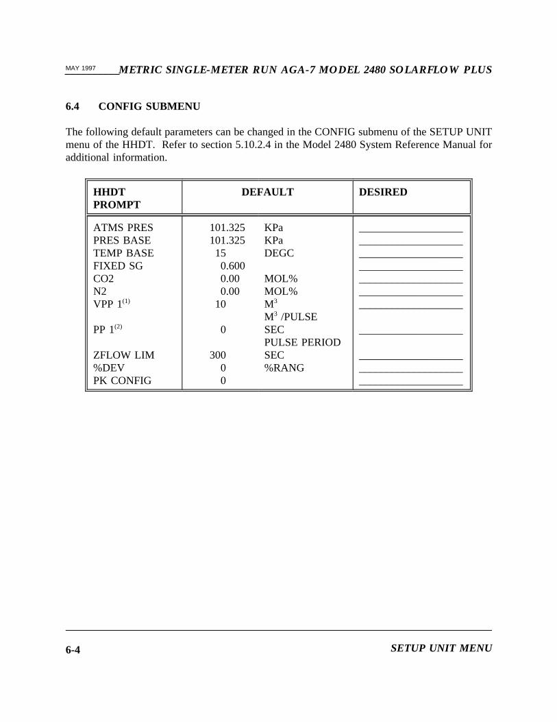
6.4 CONFIG SUBMENU
The following default parameters can be changed in the CONFIG submenu of the SETUP UNITmenu of the HHDT. Refer to section 5.10.2.4 in the Model 2480 System Reference Manual foradditional information.
HHDTPROMPT
DEFAULT DESIRED
ATMS PRESPRES BASETEMP BASEFIXED SGCO2N2VPP 1(1)
PP 1(2)
ZFLOW LIM%DEVPK CONFIG
101.325101.325150.6000.000.00
10
0
30000
KPaKPaDEGC
MOL%MOL%M3
M3 /PULSESECPULSE PERIODSEC%RANG
_____________________________________________________________________________________________________________________________________
___________________
_________________________________________________________
SETUP UNIT MENU6-4

METRIC SINGLE-METER RUN AGA-7 MODEL 2480 SOLARFLOW PLUS__________MAY 1997
NOTE: (1) VPP1 is not the same as the output on channel 5 (VP1).VP1 is a output pulse representing corrected stationvolume. VPP1 is a scaling factor for VP1 in cubic metersper pulse (M3 per pulse). The number of cubic meters perpulse can be modified using the HHDT. As indicated inthe table, the scaling factor in M3 per pulse is 10.
(2) The pulse period can be modified using the HHDT. Asindicated in the table, no pulses are generated by PP1 sincethe pulse period is set at zero (0) seconds. The value canbe changed to provide a pulse to drive an external device.For example, resetting PP1 to 1 would generate a pulse 1second in duration. The value for PP1 must be an integerequal to 1 or greater. Fractions of a second are notpermitted.
SECTION 6 6-5
__________METRIC SINGLE-METER RUN AGA-7 MODEL 2480 SOLARFLOW PLUSMAY 1997
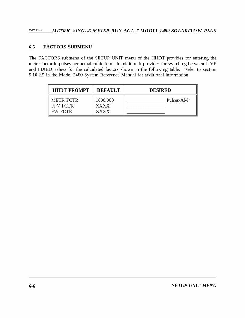
6.5 FACTORS SUBMENU
The FACTORS submenu of the SETUP UNIT menu of the HHDT provides for entering themeter factor in pulses per actual cubic foot. In addition it provides for switching between LIVEand FIXED values for the calculated factors shown in the following table. Refer to section5.10.2.5 in the Model 2480 System Reference Manual for additional information.
HHDT PROMPT DEFAULT DESIRED
METR FCTRFPV FCTRFW FCTR
1000.000XXXXXXXX
________________ Pulses/AM3
________________________________
SETUP UNIT MENU6-6
METRIC SINGLE-METER RUN AGA-7 MODEL 2480 SOLARFLOW PLUS__________MAY 1997
SECTION 7
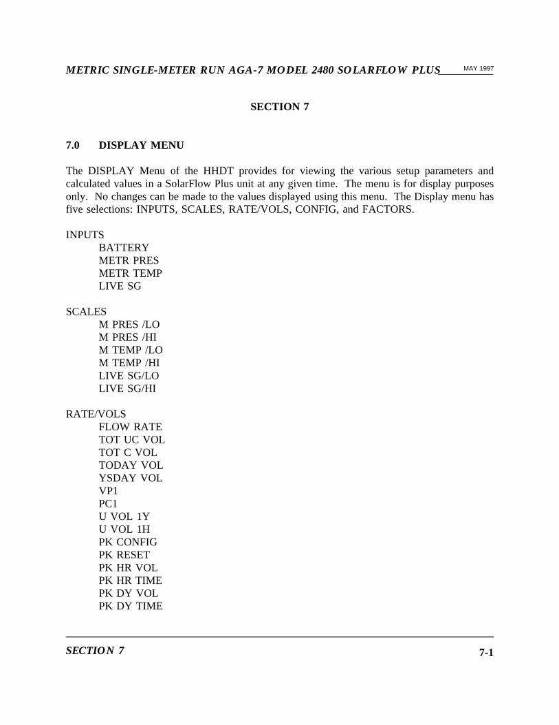
7.0 DISPLAY MENU
The DISPLAY Menu of the HHDT provides for viewing the various setup parameters andcalculated values in a SolarFlow Plus unit at any given time. The menu is for display purposesonly. No changes can be made to the values displayed using this menu. The Display menu hasfive selections: INPUTS, SCALES, RATE/VOLS, CONFIG, and FACTORS.
INPUTSBATTERYMETR PRESMETR TEMPLIVE SG
SCALESM PRES /LOM PRES /HIM TEMP /LOM TEMP /HILIVE SG/LOLIVE SG/HI
RATE/VOLSFLOW RATETOT UC VOLTOT C VOLTODAY VOLYSDAY VOLVP1PC1U VOL 1YU VOL 1HPK CONFIGPK RESETPK HR VOLPK HR TIMEPK DY VOLPK DY TIME
SECTION 7 7-1

__________METRIC SINGLE-METER RUN AGA-7 MODEL 2480 SOLARFLOW PLUSMAY 1997
CONFIGATMS PRESPRES BASETEMP BASEFIXED SGCO2N2VPP 1PP 1ZFLOW LIM%DEVPK CONFIG
FACTORSMETR FCTRFPV FCTRFW FCTR
FLW AVERAGESAVG PRS YAVG TEMP YAVG PRES HAVG TEMP H
MAX/MINIMUMSPRES MINPRES MAXFRT MINFRT MAX
DISPLAY MENU7-2

METRIC SINGLE-METER RUN AGA-7 MODEL 2480 SOLARFLOW PLUS__________MAY 1997
INTEGRATOR EXTAV FL SP HAVG SP HTIME IDX HFLW TEMP HFLW PRES HAV FL SP YAVG SP YTIME IDX YFLW TEMP YFLW PRES YFLW TIME HFLW TIME Y
SECTION 7 7-3

__________METRIC SINGLE-METER RUN AGA-7 MODEL 2480 SOLARFLOW PLUSMAY 1997
This page intentionally left blank.
DISPLAY MENU7-4

METRIC SINGLE-METER RUN AGA-7 MODEL 2480 SOLARFLOW PLUS__________MAY 1997
SECTION 8
8.0 CALIBRATE UNIT MENU
The CALIBRATE UNIT menu provides for calibrating the SolarFlow Plus input circuitry tomatch the output of the transmitter for analog inputs to the SolarFlow Plus unit. TheCALIBRATE UNIT menu has two selections: PRESSURES and OTHERS. Refer to section5.11 in the Model 2480 System Reference Manual for additional information.
8.1 PRESSURES
The PRESSURES selection of the CALIBRATE UNIT menu provides for calibrating the pressureinputs listed below.
METR PRES
8.2 OTHERS
The analog inputs listed below are calibrated in the OTHERS selection of the CALIBRATEUNIT menu.
METR TEMPLIVE SG
SECTION 8 8-1

__________METRIC SINGLE-METER RUN AGA-7 MODEL 2480 SOLARFLOW PLUSMAY 1997
This page intentionally left blank.
CALIBRATE UNIT MENU8-2

METRIC SINGLE-METER RUN AGA-7 MODEL 2480 SOLARFLOW PLUS__________MAY 1997
SECTION 9
9.0 MONITOR MENU
The Monitor menu provides for witness testing analog inputs to the SolarFlow Plus unit. Whenthe MONITOR menu is entered, all analog inputs are fixed at the values being transmitted toSolarFlow Plus when MONITOR is executed. The values remain fixed until the MONITORmenu is exited. This analog inputs listed below are available in the MONITOR menu in thesingle-meter AGA-7 application. Refer to section 5.13.8 in the Model 2480 System ReferenceManual for additional information.
METR PRESMETR TEMPLIVE SG
SECTION 9 9-1

__________METRIC SINGLE-METER RUN AGA-7 MODEL 2480 SOLARFLOW PLUSMAY 1997
This page intentionally left blank.
MONITOR MENU9-2
METRIC SINGLE-METER RUN AGA-7 MODEL 2480 SOLARFLOW PLUS__________MAY 1997
SECTION 10
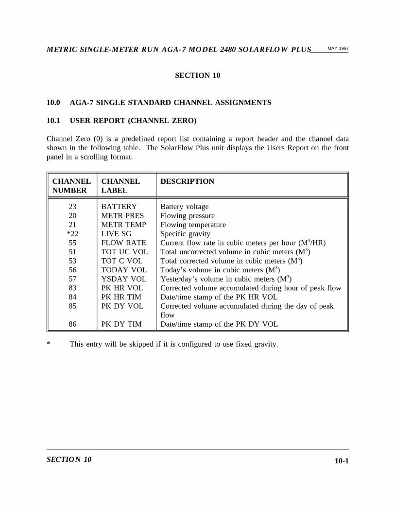
10.0 AGA-7 SINGLE STANDARD CHANNEL ASSIGNMENTS
10.1 USER REPORT (CHANNEL ZERO)
Channel Zero (0) is a predefined report list containing a report header and the channel datashown in the following table. The SolarFlow Plus unit displays the Users Report on the frontpanel in a scrolling format.
CHANNELNUMBER
CHANNELLABEL
DESCRIPTION
232021*225551535657838485
86
BATTERYMETR PRESMETR TEMPLIVE SGFLOW RATETOT UC VOLTOT C VOLTODAY VOLYSDAY VOLPK HR VOLPK HR TIMPK DY VOL
PK DY TIM
Battery voltageFlowing pressureFlowing temperatureSpecific gravityCurrent flow rate in cubic meters per hour (M3/HR)Total uncorrected volume in cubic meters (M3)Total corrected volume in cubic meters (M3)Today’s volume in cubic meters (M3)Yesterday’s volume in cubic meters (M3)Corrected volume accumulated during hour of peak flowDate/time stamp of the PK HR VOLCorrected volume accumulated during the day of peakflowDate/time stamp of the PK DY VOL
* This entry will be skipped if it is configured to use fixed gravity.
SECTION 10 10-1

__________METRIC SINGLE-METER RUN AGA-7 MODEL 2480 SOLARFLOW PLUSMAY 1997
10.2 CHANNEL ONE THROUGH 18 ASSIGNMENTS
Assignments for the single meter AGA-7 application channels one through 18 are tabulated asfollows:
CH LABEL INPUT/OUTPUT
0-LABEL
1-LABEL
DEFAULT DESCRIPTION
*1 Fixed Inp YES NO -- Fixed gravity inuse
2 PK Reset Inp YES NO YES=reset peakvol/date/timestamp
003 through 004 are reserved for later use
5 VP1 OUT OFF ON OFF Volume Pulseoutput 1
006 through 008 are reserved for later use
009 through 018 are unavailable
* The "0-Label" for a status input, "Inp", lists the condition of the input when it is shortedto common. The "1-Label" lists the condition of the input when it is left open. Forexample Channel 1 is a status input labeled "FIXED" which is used to signify the use ofa fixed or live specific gravity value in the calculations. The "0-Label" is "YES" whichmeans "use the FIXED value". The "1-Label" is "NO" which means do not use theFIXED value, use the LIVE value.
AGA-7 SINGLE STANDARD CHANNEL ASSIGNMENTS10-2
METRIC SINGLE-METER RUN AGA-7 MODEL 2480 SOLARFLOW PLUS__________MAY 1997
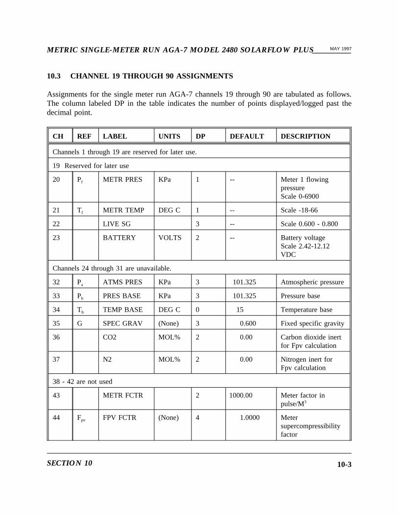
10.3 CHANNEL 19 THROUGH 90 ASSIGNMENTS
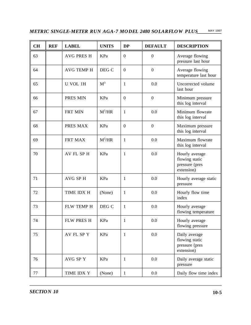
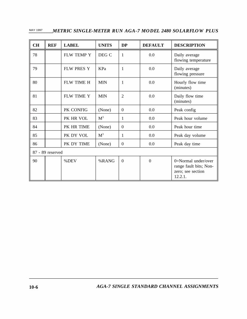
Assignments for the single meter run AGA-7 channels 19 through 90 are tabulated as follows.The column labeled DP in the table indicates the number of points displayed/logged past thedecimal point.
CH REF LABEL UNITS DP DEFAULT DESCRIPTION
Channels 1 through 19 are reserved for later use.
19 Reserved for later use
20 Pf METR PRES KPa 1 -- Meter 1 flowingpressureScale 0-6900
21 Tf METR TEMP DEG C 1 -- Scale -18-66
22 LIVE SG 3 -- Scale 0.600 - 0.800
23 BATTERY VOLTS 2 -- Battery voltageScale 2.42-12.12VDC
Channels 24 through 31 are unavailable.
32 Pa ATMS PRES KPa 3 101.325 Atmospheric pressure
33 Pb PRES BASE KPa 3 101.325 Pressure base
34 Tb TEMP BASE DEG C 0 15 Temperature base
35 G SPEC GRAV (None) 3 0.600 Fixed specific gravity
36 CO2 MOL% 2 0.00 Carbon dioxide inertfor Fpv calculation
37 N2 MOL% 2 0.00 Nitrogen inert forFpv calculation
38 - 42 are not used
43 METR FCTR 2 1000.00 Meter factor inpulse/M3
44 Fpv FPV FCTR (None) 4 1.0000 Metersupercompressibilityfactor
SECTION 10 10-3
__________METRIC SINGLE-METER RUN AGA-7 MODEL 2480 SOLARFLOW PLUSMAY 1997
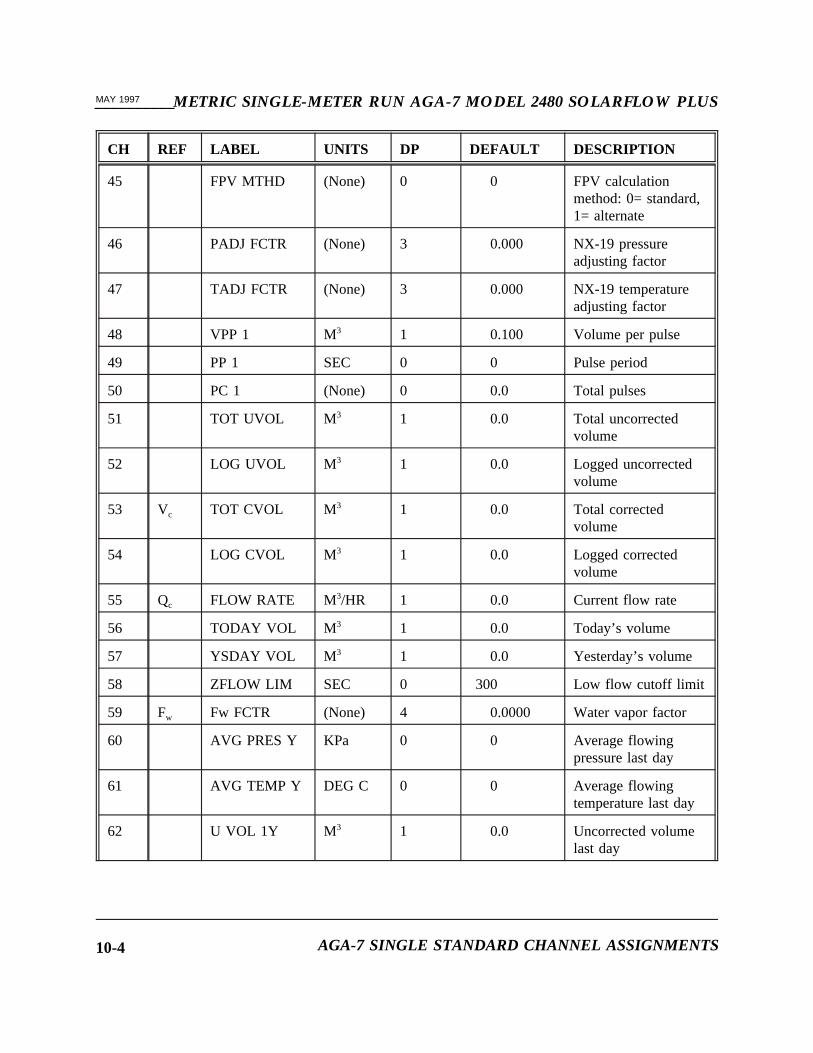
CH REF LABEL UNITS DP DEFAULT DESCRIPTION
45 FPV MTHD (None) 0 0 FPV calculationmethod: 0= standard,1= alternate
46 PADJ FCTR (None) 3 0.000 NX-19 pressureadjusting factor
47 TADJ FCTR (None) 3 0.000 NX-19 temperatureadjusting factor
48 VPP 1 M3 1 0.100 Volume per pulse
49 PP 1 SEC 0 0 Pulse period
50 PC 1 (None) 0 0.0 Total pulses
51 TOT UVOL M3 1 0.0 Total uncorrectedvolume
52 LOG UVOL M3 1 0.0 Logged uncorrectedvolume
53 Vc TOT CVOL M3 1 0.0 Total correctedvolume
54 LOG CVOL M3 1 0.0 Logged correctedvolume
55 Qc FLOW RATE M3/HR 1 0.0 Current flow rate
56 TODAY VOL M3 1 0.0 Today’s volume
57 YSDAY VOL M3 1 0.0 Yesterday’s volume
58 ZFLOW LIM SEC 0 300 Low flow cutoff limit
59 Fw Fw FCTR (None) 4 0.0000 Water vapor factor
60 AVG PRES Y KPa 0 0 Average flowingpressure last day
61 AVG TEMP Y DEG C 0 0 Average flowingtemperature last day
62 U VOL 1Y M3 1 0.0 Uncorrected volumelast day
AGA-7 SINGLE STANDARD CHANNEL ASSIGNMENTS10-4
METRIC SINGLE-METER RUN AGA-7 MODEL 2480 SOLARFLOW PLUS__________MAY 1997
CH REF LABEL UNITS DP DEFAULT DESCRIPTION
63 AVG PRES H KPa 0 0 Average flowingpressure last hour
64 AVG TEMP H DEG C 0 0 Average flowingtemperature last hour
65 U VOL 1H M3 1 0.0 Uncorrected volumelast hour
66 PRES MIN KPa 0 0 Minimum pressurethis log interval
67 FRT MIN M3/HR 1 0.0 Minimum flowratethis log interval
68 PRES MAX KPa 0 0 Maximum pressurethis log interval
69 FRT MAX M3/HR 1 0.0 Maximum flowratethis log interval
70 AV FL SP H KPa 1 0.0 Hourly averageflowing staticpressure (presextension)
71 AVG SP H KPa 1 0.0 Hourly average staticpressure
72 TIME IDX H (None) 1 0.0 Hourly flow timeindex
73 FLW TEMP H DEG C 1 0.0 Hourly averageflowing temperature
74 FLW PRES H KPa 1 0.0 Hourly averageflowing pressure
75 AV FL SP Y KPa 1 0.0 Daily averageflowing staticpressure (presextension)
76 AVG SP Y KPa 1 0.0 Daily average staticpressure
77 TIME IDX Y (None) 1 0.0 Daily flow time index
SECTION 10 10-5
__________METRIC SINGLE-METER RUN AGA-7 MODEL 2480 SOLARFLOW PLUSMAY 1997
CH REF LABEL UNITS DP DEFAULT DESCRIPTION
78 FLW TEMP Y DEG C 1 0.0 Daily averageflowing temperature
79 FLW PRES Y KPa 1 0.0 Daily averageflowing pressure
80 FLW TIME H MIN 1 0.0 Hourly flow time(minutes)
81 FLW TIME Y MIN 2 0.0 Daily flow time(minutes)
82 PK CONFIG (None) 0 0.0 Peak config
83 PK HR VOL M3 1 0.0 Peak hour volume
84 PK HR TIME (None) 0 0.0 Peak hour time
85 PK DY VOL M3 1 0.0 Peak day volume
86 PK DY TIME (None) 0 0.0 Peak day time
87 - 89 reserved
90 %DEV %RANG 0 0 0=Normal under/overrange fault bits; Non-zero; see section12.2.1.
AGA-7 SINGLE STANDARD CHANNEL ASSIGNMENTS10-6
METRIC SINGLE-METER RUN AGA-7 MODEL 2480 SOLARFLOW PLUS__________MAY 1997
SECTION 11
11.0 DATA LOG LIST AND HEADER BLOCK
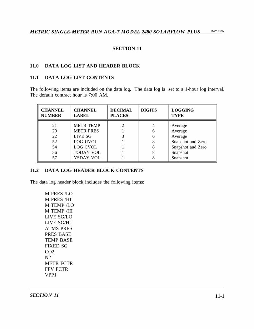
11.1 DATA LOG LIST CONTENTS
The following items are included on the data log. The data log is set to a 1-hour log interval.The default contract hour is 7:00 AM.
CHANNELNUMBER
CHANNELLABEL
DECIMALPLACES
DIGITS LOGGINGTYPE
21202252545657
METR TEMPMETR PRESLIVE SGLOG UVOLLOG CVOLTODAY VOLYSDAY VOL
2131111
4668888
AverageAverageAverageSnapshot and ZeroSnapshot and ZeroSnapshotSnapshot
11.2 DATA LOG HEADER BLOCK CONTENTS
The data log header block includes the following items:
M PRES /LOM PRES /HIM TEMP /LOM TEMP /HILIVE SG/LOLIVE SG/HIATMS PRESPRES BASETEMP BASEFIXED SGCO2N2METR FCTRFPV FCTRVPP1
SECTION 11 11-1
__________METRIC SINGLE-METER RUN AGA-7 MODEL 2480 SOLARFLOW PLUSMAY 1997
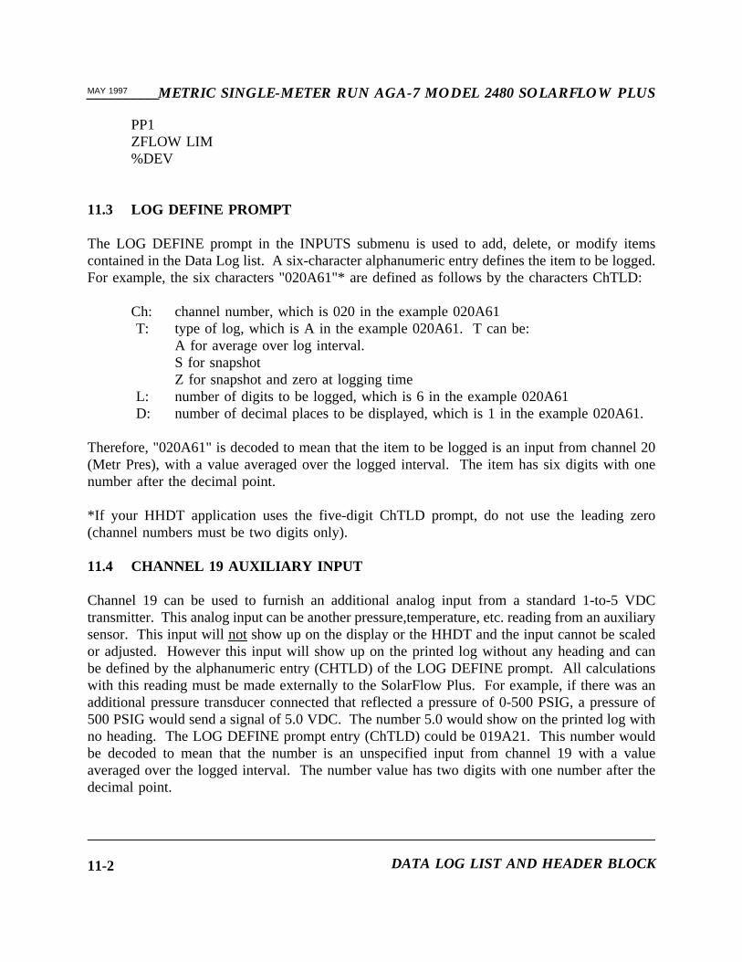
PP1ZFLOW LIM%DEV
11.3 LOG DEFINE PROMPT
The LOG DEFINE prompt in the INPUTS submenu is used to add, delete, or modify itemscontained in the Data Log list. A six-character alphanumeric entry defines the item to be logged.For example, the six characters "020A61"* are defined as follows by the characters ChTLD:
Ch: channel number, which is 020 in the example 020A61T: type of log, which is A in the example 020A61. T can be:
A for average over log interval.S for snapshotZ for snapshot and zero at logging time
L: number of digits to be logged, which is 6 in the example 020A61D: number of decimal places to be displayed, which is 1 in the example 020A61.
Therefore, "020A61" is decoded to mean that the item to be logged is an input from channel 20(Metr Pres), with a value averaged over the logged interval. The item has six digits with onenumber after the decimal point.
*If your HHDT application uses the five-digit ChTLD prompt, do not use the leading zero(channel numbers must be two digits only).
11.4 CHANNEL 19 AUXILIARY INPUT
Channel 19 can be used to furnish an additional analog input from a standard 1-to-5 VDCtransmitter. This analog input can be another pressure,temperature, etc. reading from an auxiliarysensor. This input will notshow up on the display or the HHDT and the input cannot be scaledor adjusted. However this input will show up on the printed log without any heading and canbe defined by the alphanumeric entry (CHTLD) of the LOG DEFINE prompt. All calculationswith this reading must be made externally to the SolarFlow Plus. For example, if there was anadditional pressure transducer connected that reflected a pressure of 0-500 PSIG, a pressure of500 PSIG would send a signal of 5.0 VDC. The number 5.0 would show on the printed log withno heading. The LOG DEFINE prompt entry (ChTLD) could be 019A21. This number wouldbe decoded to mean that the number is an unspecified input from channel 19 with a valueaveraged over the logged interval. The number value has two digits with one number after thedecimal point.
DATA LOG LIST AND HEADER BLOCK11-2
METRIC SINGLE-METER RUN AGA-7 MODEL 2480 SOLARFLOW PLUS__________MAY 1997
SECTION 12
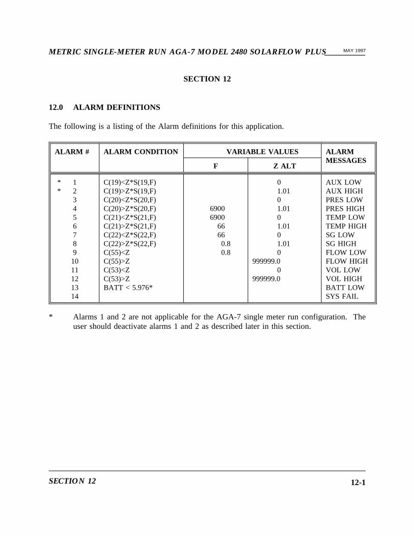
12.0 ALARM DEFINITIONS
The following is a listing of the Alarm definitions for this application.
ALARM # ALARM CONDITION VARIABLE VALUES ALARMMESSAGES
F Z ALT
* 1* 2
34567891011121314
C(19)<Z*S(19,F)C(19)>Z*S(19,F)C(20)<Z*S(20,F)C(20)>Z*S(20,F)C(21)<Z*S(21,F)C(21)>Z*S(21,F)C(22)<Z*S(22,F)C(22)>Z*S(22,F)C(55)<ZC(55)>ZC(53)<ZC(53)>ZBATT < 5.976*
69006900
66660.80.8
01.0101.0101.0101.010
999999.00
999999.0
AUX LOWAUX HIGHPRES LOWPRES HIGHTEMP LOWTEMP HIGHSG LOWSG HIGHFLOW LOWFLOW HIGHVOL LOWVOL HIGHBATT LOWSYS FAIL
* Alarms 1 and 2 are not applicable for the AGA-7 single meter run configuration. Theuser should deactivate alarms 1 and 2 as described later in this section.
SECTION 12 12-1

__________METRIC SINGLE-METER RUN AGA-7 MODEL 2480 SOLARFLOW PLUSMAY 1997
12.1 CALCULATING ALARM SETPOINTS
Alarm setpoints are calculated using the equation shown under the Alarm Condition column inthe table shown above. For example, to calculate the setpoint for Alarm #4, the equation shownis:
Setpoint = Z * S(20,F)
Where:
Z = 1.01F = 6900S(20,F) = The full scale value for channel 20, which is the meter pressure
transmitter. The Model 2480 automatically generates this value based onthe full scale value entered in the SETUP UNIT menu.
Therefore:
The setpoint for Alarm #4 is = 1.01 * 6900 = 6969
When the ALARM menu is entered using the HHDT the user may modify the Z value shownin the above alarm conditions by changing the value for ALT. This enables the user to adjustthe alarm limit to match the requirements.
The value for Z is represented by ALT on the HHDT ALARM SETUP menu.
The ALARM menu is also used to acknowledge alarms and to activate or deactivate alarms.
To acknowledge an alarm condition displayed on the LCD of SolarFlow Plus, enter the ALARMmenu of the HHDT and select the ACKNOWLEDGE sub-menu. Any existing un-acknowledgedalarms are displayed and the HHDT prompts: "ACKNOWLEDGE ? Y/N". Press the ENTER keyto acknowledge the alarm. Once this has been done and the user has logged off SolarFlow Plusthe activated alarm is displayed with the message "ACKNOWLEDGED" following the alarmcondition. If the alarm condition no longer exists and has not been acknowledged it remains onthe LCD until acknowledged.
ALARM DEFINITIONS12-2
METRIC SINGLE-METER RUN AGA-7 MODEL 2480 SOLARFLOW PLUS__________MAY 1997
To activate or deactivate alarms, enter the HHDT ALARM menu and select the SETUPsub-menu. The HHDT displays the various alarms that are available in the program. Scroll tothe desired alarm and press the ENTER key at the desired alarm condition. The HHDT providesfour options; STAT, LOW, HIGH, and ALT. Press ENTER at the STAT option. The HHDTshows either ON or OFF and prompts OK?. To turn off the alarm, press the NO key until OFFis displayed, then press ENTER.
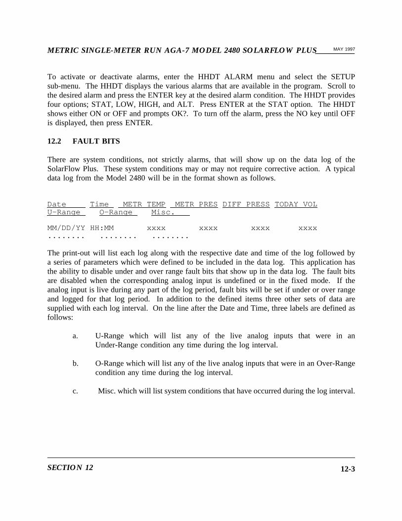
12.2 FAULT BITS
There are system conditions, not strictly alarms, that will show up on the data log of theSolarFlow Plus. These system conditions may or may not require corrective action. A typicaldata log from the Model 2480 will be in the format shown as follows.
Date Time METR TEMP METR PRESDIFF PRESS TODAY VOLU-Range O-Range Misc.
MM/DD/YY HH:MM xxxx xxxx xxxx xxxx........ ........ ........
The print-out will list each log along with the respective date and time of the log followed bya series of parameters which were defined to be included in the data log. This application hasthe ability to disable under and over range fault bits that show up in the data log. The fault bitsare disabled when the corresponding analog input is undefined or in the fixed mode. If theanalog input is live during any part of the log period, fault bits will be set if under or over rangeand logged for that log period. In addition to the defined items three other sets of data aresupplied with each log interval. On the line after the Date and Time, three labels are defined asfollows:
a. U-Range which will list any of the live analog inputs that were in anUnder-Range condition any time during the log interval.
b. O-Range which will list any of the live analog inputs that were in an Over-Rangecondition any time during the log interval.
c. Misc. which will list system conditions that have occurred during the log interval.
SECTION 12 12-3

__________METRIC SINGLE-METER RUN AGA-7 MODEL 2480 SOLARFLOW PLUSMAY 1997
A series of eight decimal points ( ........ ) are shown under the respective data log interval Dateand Time. If none of the analog inputs were in an under or over range condition, decimal pointswill be displayed. If any of the factory defined analog inputs are out of range, a number willreplace one of the decimal points. For example, if Channels 20 and 21 were Under Range thefollowing would be displayed.
Date TimeU-Range O-Range
MM/DD/YY HH:MM.23..... ........
The "2" replacing the second decimal point indicates channel 20 is Under-Range. The "3" inplace of the third decimal point indicates channel 21 is Under-Range and so-on. This samesequence applies to the Over-Range conditions.
The following table lists the applicable analog input for each of the decimal points under the"U-Range" and "O-Range" identifiers.
AGA-3 2480 SNGL
DECIMAL POINT ANALOG INPUT
12345
6-8
(AUX AIN1)Meter pressure, Channel 20Meter temperature, Channel 21Live SG, Channel 22Battery, Channel 23Not Used
ALARM DEFINITIONS12-4

METRIC SINGLE-METER RUN AGA-7 MODEL 2480 SOLARFLOW PLUS__________MAY 1997
The "Misc." section is applicable for system conditions that were present during the log interval.The conditions defined as "1" through "8" are detailed as follows:
1 - Not used2 - Fpv adjusted pressure out of range3 - Fpv adjusted temperature out of range4 - not used5 - Not used6 - Warm start was enacted during interval7 - Cold start was enacted during interval8 - System fault
12.2.1 Redefined Over/Under Range Fault Bits
When channel 90, %DEV, is zero, the under-range and over-range fault bits in the data logfunction normally. When %DEV is changed to some non-zero value, the meaning of the faultbits is changed such that the item labelled "under-range" indicates under or over range and theitem labelled "over-range" indicates a deviation during the log interval. The deviation iscomputed internally in the SolarFlow Plus by:
· averaging each analog input over the log interval
· computing the maximum of each input over the log interval
· computing the minimum of each input over the log interval
· computing the deviation, as a percentage of full scale, of both maximum andminimum from the average.
If the deviation is greater than or equal to the non-zero value the operator has configured into%DEV, then the deviation fault bit for that input is set.
SECTION 12 12-5

__________METRIC SINGLE-METER RUN AGA-7 MODEL 2480 SOLARFLOW PLUSMAY 1997
This page intentionally left blank.
ALARM DEFINITIONS12-6

METRIC SINGLE-METER RUN AGA-7 MODEL 2480 SOLARFLOW PLUS__________MAY 1997
SECTION 13
13.0 MODEL 1882 PREAMPLIFIER
Model 1882 Preamplifier is a low power preamplifier that works with the Model 2480 to increasethe frequency of the allowed pulse inputs. Model 1882 Preamplifier enables the PositiveDisplacement (PD) inputs to be in a frequency range between zero and 5000 Hz. It is locatedin an explosion proof condulet that is mounted close to the pick-up coil of the PD meter. It isdesigned to accept a balanced input from a pick-up coil and provide a zero to a five VDCminimum pulse to the input of the Model 2480 flow computer. There is no maintenance requiredon this unit. Replace it if necessary.
13.1 MODEL 1882 INSTALLATION
For the Model 2480 to work with the Model 1882 Preamplifier, two capacitors (C21 and C22)must be removed from the CPU board on Model 2480. See Figure 13-1. In later Model 2480units, the capacitors are located in sockets on the CPU board and may be pulled out with yourfingers. The output from the Model 1882 Preamplifier should be connected to the Model 2480at the standard turbine or PD input terminals (pins 17 and 18) on the termination board. Referto the wiring diagrams in the Model 2480 System Reference manual as necessary.
SECTION 13 13-1

__________METRIC SINGLE-METER RUN AGA-7 MODEL 2480 SOLARFLOW PLUSMAY 1997
Figure 13-1. Location of Capacitors C21 and C22
MODEL 1882 PREAMPLIFIER13-2

METRIC SINGLE-METER RUN AGA-7 MODEL 2480 SOLARFLOW PLUS__________MAY 1997
13.2 MODEL 1882 SPECIFICATIONS
13.2.1 ELECTRICAL
Input pick-up coil
Frequency range 1 - 5 KHz
Minimum signal level 6 millivolts p-p at 10 KHZ
Maximum signal level 8 volts p-p at 5 KHZ
Maximum distance from pick-up coil Two feet
Output signal level with 6 volts applied High minimum 5.3 volts at 1.8 mA sourceLow maximum 0.6 volts at 1.8 mA sink
Maximum distance from preamp toModel 2480
100 feet
Power requirement 5-9 volts at 2 mA maximum
13.2.2 ENVIRONMENTAL
Operating Temperature -20 to +160 degrees F.
Humidity 0 to 95 % non-condensing
13.2.3 MECHANICAL
Dimensions 1-5/8" W x 1" H x 3" L
Weight Approximately 8 ounces
Mounting two sets of 4 x 40 x 1-1/4" RH screws with lockwashers
SECTION 13 13-3

__________METRIC SINGLE-METER RUN AGA-7 MODEL 2480 SOLARFLOW PLUSMAY 1997
This page intentionally left blank.
MODEL 1882 PREAMPLIFIER13-4

METRIC SINGLE-METER RUN AGA-7 MODEL 2480 SOLARFLOW PLUS__________MAY 1997
SECTION 14
14.0 RADIO COMMUNICATION
This software may be used for radio communication only with Daniel PC software that supports"Radio Packetized Logon". The "Radio Packetized Logon" is active in SolarFlow Plus whenevera radio interface is installed, no local HHDT cable is plugged in, and RTS DELAY is set to somenon-zero value. Consult the manual for your Daniel PC software to determine whether itsupports this feature.
SECTION 14 14-1

__________METRIC SINGLE-METER RUN AGA-7 MODEL 2480 SOLARFLOW PLUSMAY 1997
This page intentionally left blank.
RADIO COMMUNICATION14-2
METRIC SINGLE-METER RUN AGA-7 MODEL 2480 SOLARFLOW PLUS__________MAY 1997
SECTION 15
15.0 USER LOGON EVENT
This application generates a "User logged on" record in the Event log only if the user performedan action (e.g. changed a measurement parameter, etc.) which generates another event. In otherwords, no event log entry is made when a user logs on and just reads current values.
SECTIONSECTION 1515 15-1

__________METRIC SINGLE-METER RUN AGA-7 MODEL 2480 SOLARFLOW PLUSMAY 1997
This page intentionally left blank.
USERUSER LOGONLOGON EVENTEVENT15-2

METRIC SINGLE-METER RUN AGA-7 MODEL 2480 SOLARFLOW PLUS__________MAY 1997
SECTION 16
16.0 HIGH SPEED CHANNEL READS
This application supports high speed channel reads with DSI protocol.
SECTIONSECTION 1616 16-1

__________METRIC SINGLE-METER RUN AGA-7 MODEL 2480 SOLARFLOW PLUSMAY 1997
This page intentionally left blank.
HIGHHIGH SPEEDSPEED CHANNELCHANNEL READSREADS16-2
METRIC SINGLE-METER RUN AGA-7 MODEL 2480 SOLARFLOW PLUS__________MAY 1997
SECTION 17
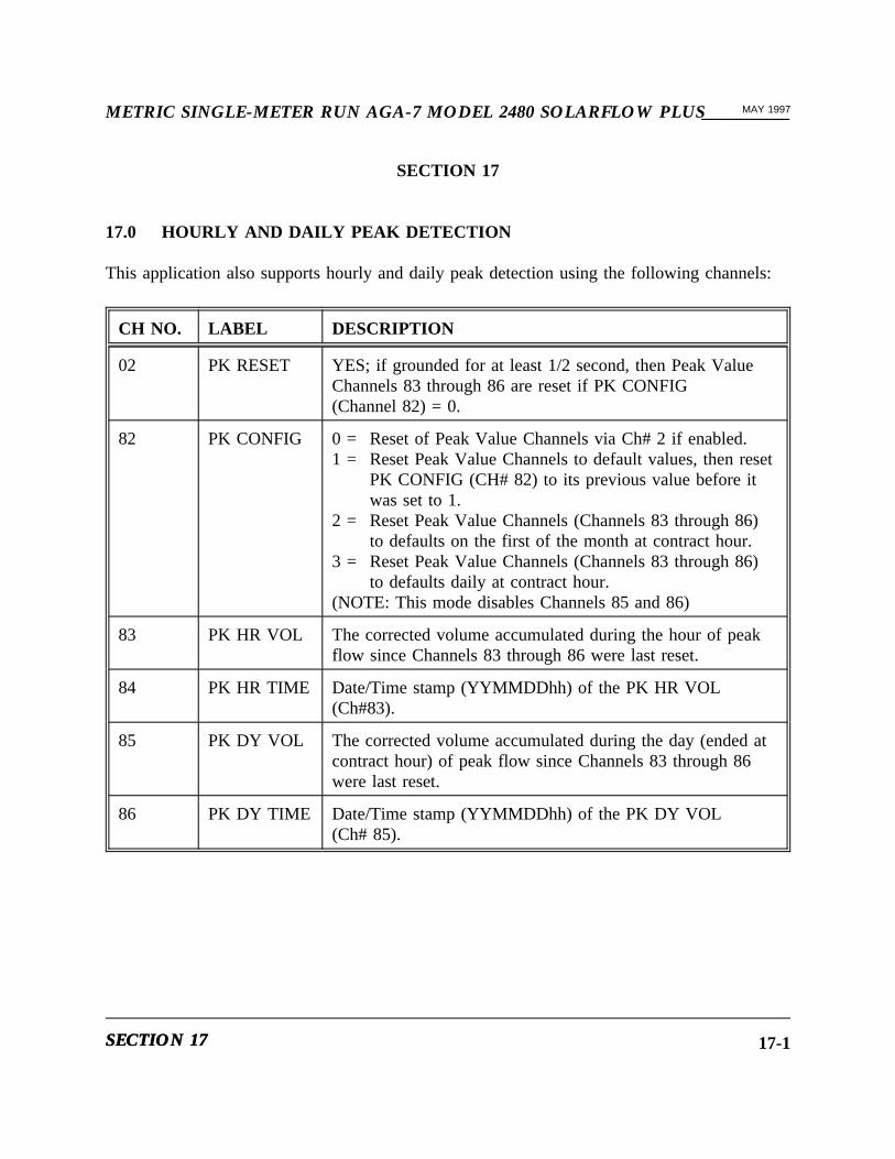
17.0 HOURLY AND DAILY PEAK DETECTION
This application also supports hourly and daily peak detection using the following channels:
CH NO. LABEL DESCRIPTION
02 PK RESET YES; if grounded for at least 1/2 second, then Peak ValueChannels 83 through 86 are reset if PK CONFIG(Channel 82) = 0.
82 PK CONFIG 0 = Reset of Peak Value Channels via Ch# 2 if enabled.1 = Reset Peak Value Channels to default values, then reset
PK CONFIG (CH# 82) to its previous value before itwas set to 1.
2 = Reset Peak Value Channels (Channels 83 through 86)to defaults on the first of the month at contract hour.
3 = Reset Peak Value Channels (Channels 83 through 86)to defaults daily at contract hour.
(NOTE: This mode disables Channels 85 and 86)
83 PK HR VOL The corrected volume accumulated during the hour of peakflow since Channels 83 through 86 were last reset.
84 PK HR TIME Date/Time stamp (YYMMDDhh) of the PK HR VOL(Ch#83).
85 PK DY VOL The corrected volume accumulated during the day (ended atcontract hour) of peak flow since Channels 83 through 86were last reset.
86 PK DY TIME Date/Time stamp (YYMMDDhh) of the PK DY VOL(Ch# 85).
SECTIONSECTION 1717 17-1

__________METRIC SINGLE-METER RUN AGA-7 MODEL 2480 SOLARFLOW PLUSMAY 1997
This page intentionally left blank.
HOURLYHOURLY ANDAND DAILYDAILY PEAKPEAK DETECTIONDETECTION17-2

WARRANTY CLAIM REQUIREMENTS
To make a warranty claim, you, the Purchaser, must:
1. Provide Daniel with proof of the Date of Purchase and proof of the Date of Shipment ofthe product in question.
2. Return the product to Daniel within twelve (12) months of the date of original shipmentof the product, or within eighteen (18) months of the date of original shipment of theproduct to destinations outside of the United States. The Purchaser must prepay anyshipping charges. In addition, the Purchaser is responsible for insuring any productshipped for return, and assumes the risk of loss of the product during shipment.
3. To obtain Warranty service or to locate the nearest Daniel office, sales, or service centercall (281) 897-2900, Fax (281) 897-2901, or contact:
Daniel Measurement Services19203 Hempstead HighwayHouston, Texas 77065
When contacting Daniel for product service, the purchaser is asked to provideinformation as indicated on the following "Customer Problem Report".
Daniel Measurement Services offers both on call and contract maintenance servicedesigned to afford single source responsibility for all its products.
Daniel Industries, Inc. reserves the right to make changes at any time to any product toimprove its design and to insure the best available product.


DANIEL INDUSTRIES, INC.CUSTOMER PROBLEM REPORT
FOR FASTEST SERVICE, COMPLETE THIS FORM, AND RETURN IT ALONG WITH THE AFFECTEDEQUIPMENT TO CUSTOMER SERVICE AT THE ADDRESS INDICATED BELOW.
COMPANY NAME:____________________________________________________________________________
TECHNICAL CONTACT:_________________________________ PHONE:______________________________
REPAIR P. O. #:_____________________________ IF WARRANTY, UNIT S/N:_________________________
INVOICE ADDRESS:____________________________________________________________________
_________________________________________________________________
_________________________________________________________________
SHIPPING ADDRESS:___________________________________________________________________
_________________________________________________________________
_________________________________________________________________
RETURN SHIPPING METHOD:__________________________________________________________________
EQUIPMENT MODEL #:____________________ S/N:__________________FAILURE DATE:_____________
DESCRIPTION OF PROBLEM:__________________________________________________________________
______________________________________________________________________________________________
______________________________________________________________________________________________
WHAT WAS HAPPENING AT TIME OF FAILURE?________________________________________________
______________________________________________________________________________________________
ADDITIONAL COMMENTS:____________________________________________________________________
______________________________________________________________________________________________
______________________________________________________________________________________________
REPORT PREPARED BY:________________________________ TITLE:________________________________
IF YOU REQUIRE TECHNICAL ASSISTANCE, PLEASE FAX OR WRITE THE MAIN CUSTOMER SERVICEDEPARTMENT AT:
DANIEL MEASUREMENT SERVICES PHONE: (281) 897-2900ATTN: CUSTOMER SERVICE FAX: (281) 897-290119203 HEMPSTEAD HIGHWAYHOUSTON, TEXAS 77065


THIS DIGITAL APPARATUS DOES NOT EXCEED THE CLASS A LIMITS FORRADIO NOISE EMISSIONS FROM DIGITAL APPARATUS AS SET OUT IN THERADIO INTERFERENCE REGULATIONS OF THE CANADIAN DEPARTMENT OFCOMMUNICATIONS.
LE PRÉSENT APPARÉIL NUMÉRIQUE N’ÉMET PAS DES BRUITSRADIOÉLECTRIQUES DÉPASSANT LES LIMITES APPLICABLES AUX APPAREILSNUMÉRIQUES DE CLASSE A PRESCRITES DANS LE RÉGLEMENT SUR LEBROUILLAGE RADIOÉLECTRIQUE ÉDICTÉ PAR LE MINISTÉRE DESCOMMUNICATIONS DU CANADA.

The sales and service offices of Daniel Industries, Inc. are locatedthroughout the United States and in major countries overseas.
Please contact Daniel Measurement and Control at19203 Hempstead Highway, Houston, Texas 77065, or phone (281) 897-2900
for the location of the sales or service office nearest you.Daniel Measurement Services offers both on-call and contract
maintenance service designed to provide single-sourceresponsibility for all Daniel Measurement and Control products.
Daniel Measurement and Control reserves the right to make changes to any of its products or servicesat any time without prior notification in order to improve that product or service and to supply
the best product or service possible.