Embed Size (px)
Citation preview

Model 414
Color ReflectionDensitometer
Operation Manual

�
Dear Customer:
Congratulations! We at X-Rite, Incorporated are proud to present youwith the X-Rite 414 Color Reflection Densitometer. This instrumentrepresents the very latest in microcontrollers, integrated circuits,optics, and display technology. Your X-Rite 414 is a rugged, reliable,finely engineered instrument whose performance is unsurpassed.
To fully appreciate and protect your investment, we suggest that youtake the necessary time to read and fully understand this manual. Asalways, X-Rite stands behind your 414 with a full one year limitedwarranty and a dedicated service organization. If the need arises,please don’t hesitate to call us.
Thank you for your trust and confidence.
X-Rite, Incorporated

iiii
CE DECLARATION
Manufacturer's Name: X-Rite, Incorporated Manufacturer's Address: 3100 44th Street, S.W. Grandville, Michigan 49418 U.S.A. Model Name: Densitometer Model No.: 414 Directive(s) Conformance: EMC 89/336/EEC LVD 73/23/EEC
NOTE: The device complies to the product specifications for the Low Voltage Directive when furnished with the 230VAC AC Adapter (X-Rite P/N SE30-62), and to UL Standards when furnished with the 115VAC AC Adapter (X-Rite P/N SE 30-61).

���
������� ��� ��� �� � �� � �� ��
��� ���������
This equipment has been tested and found to comply with the limitsfor a Class A digital device, pursuant to Part 15 of the FCC Rules.These limits are designed to provide reasonable protection againstharmful interference when the equipment is operated in a commercialenvironment. This equipment generates, uses, and can radiate radiofrequency energy and, if not installed and used in accordance with theinstruction manual, may cause harmful interference to radiocommunications. Operation of this equipment in a residential area islikely to cause harmful interference in which case the user will berequired to correct the interference at his own expense.
������
This Class A digital apparatus meets all requirements of the CanadianInterference-Causing Equipment Regulations.
Cet appareil numérique de la classe A respecte toutes les exigencesdu Règlement sur le matériel brouilleur du Canada.
The Manufacturer: X-Rite, IncorporatedDer Hersteller: 3100 44th Street, S.W.El fabricante: Grandville, Michigan 49418Le fabricant:Il fabbricante:
Declares that: Densitometergibt bekannt: 414advierte que:avertit que:avverte che:
is not intended to be connected to a public telecommunicationsnetwork.an ein öffentliches Telekommunikations-Netzwerk nichtangeschlossen werden soll.no debe ser conectado a redes de telecomunicaciones públicas.ne doit pas être relié à un réseau de télécommunications publique.non deve essere connettuto a reti di telecomunicazioni pubblici.

��
CAUTION: Operational hazard exists if AC adaptor other thanX-Rite SE30-61 (115V) or SE30-62 (230V) is used.
VORSICHT: Es besteht Betriebsgefahr bei der Verwendung voneinem Adapter außer X-Rite SE30-61 (115 U) oder SE30-62 (230U).
AVISO: No use otro adaptador C.A. que no sea la pieza X-RiteSE30-61 (115V) o SE30-62 (230V), por el riesgo de malfuncionamiento del equipo.
ATTENTION: Ne pas utiliser d’adaptateur autre que SE30-61(115V) ou SE30-62 (230V) de X-Rite au risque de mauvaisfonctionnement de l’appareil.
AVVISO: Non usare un altro adattatore C.A. che non è del pezzoX-Rite SE30-61 (115V) o SE30-62 (230V), per il rischio dimalfunzionamento dell’apparecchio.
NOTE: Shielded interface cables must be used in order tomaintain compliance with the desired FCC and European emissionrequirements.

�
WARNING: This instrument is not for use in explosiveenvironment.
WARNUNG: Das Gerät soll in einer explosiven Umgebung NICHTverwendet werden.
ADVERTENCIA: NO use este aparato en los ambientes explosivos.
ATTENTION: Cet instrument NE DOIT PAS être utilisé dans unenvironnement explosif.
AVVERTIMENTO: NON usare questo apparecchio in ambientiesplosivi.
USE ONLY: AA NICad batteries that are 600/700mAhr rated, sixrequired. Other types may burst causing personal injury.
AUFGEPASST: Verwenden Sie nur AA Nicad Akkus von600/700mAhr (Milliampere/Stunde) Nennstrom (6 Stückerforderlich). Mit anderen Akkus läuft die Gefahr von Explosion undVerletzung.
ATENCION: Use solamente las pilas de AA NiCad (se requiereseis) con condiciones de funcionamiento normales 600/700mAhr(horas miliamperios). Es posible que los otros tipos puedan estallar ycausar daños corporales.
ATTENTION: Utiliser seulement les batteries NICad à courantnominal de 600mAh (milliampère/heure) (6 pièces nécessaire). Il y adanger d'explosion et de blessures avec les autres types.
ATTENZIONE: Usare solamente gli accumulatori al AA NiCad (sirichiede sei) con le condizioni di funzionamento normali600/700mAhr (ore milliamperi). E possibile che altri tipi possanoscoppiare e causare danno personale.
��
��������
� ������� ��� �����
Features ............................................................................... 1-1Packaging and Parts ............................................................... 1-3Instrument Vocabulary ......................................................... 1-4Unlocking/Locking the Shoe................................................. 1-5Batteries and Power ............................................................. 1-6Adjusting the Display Angle.................................................. 1-8I/O Port Setup....................................................................... 1-9
� ��������� �
Response Settings ............................................................... 2-1Overview of Calibration Procedures..................................... 2-3Long Calibration ................................................................... 2-4Color Correlation (CC) Calibration ....................................... 2-7Quick-Cal™........................................................................ 2-9
! ���"��# ���$�� �"
Selecting Density Function ................................................... 3-2Selecting Density Mode........................................................ 3-2Selecting Color Measurement Method ................................. 3-4Density Measurement .......................................................... 3-6Density Difference Measurement......................................... 3-8
% � � ���$�� �"
Selecting Dot Area or Dot Gain ............................................ 4-2Selecting Measurement Method........................................... 4-3Dot Area Function ................................................................ 4-4Dot Gain Function ................................................................ 4-5
& '��#��"" ���$�� �"
Formulas .............................................................................. 5-1Selecting Grayness Function................................................ 5-1Selecting Grayness Mode .................................................... 5-2Grayness Measurement....................................................... 5-4
( ��$)��$�� �* ����� �
Serial Interface Information .................................................. 6-1Instrument Specifications ..................................................... 6-4Accessories .......................................................................... 6-6General Cleaning.................................................................. 6-7

���
Optics Maintenance.............................................................. 6-7Target Window Replacement............................................... 6-8Lamp Replacement .............................................................. 6-9
+ �������$�" ��� ���,
Display Messages .............................................................. 7-1Proprietary Notice............................................................... 7-3Limited Warranty ................................................................ 7-4Index................................................................................... 7-5
Copyright 1998 byX-Rite, Incorporated“ALL RIGHTS RESERVED”
X-Rite is a registered trademark and Quick Cal™, Q Cal™, Electronic Function
Selection™, Computerized Color Response™, and CCR™, are trademarks of X-Rite,
Incorporated. All other logos, brand names, and product names are the properties of
their respective holders.

����

���
��� � ��������
����� �
Features..................................... 1-1Packaging and Parts..................... 1-3Instrument Vocabulary ............... 1-4Unlocking/Locking the Shoe ...... 1-5Batteries and Power................... 1-6Adjusting the Display Angle ....... 1-8I/O Port Setup ............................ 1-9
The X-Rite 414 Color Reflection Densitometer is designed to meetthe quality control needs of today’s pressroom and graphic artstechnicians. This completely portable instrument features differentmeasurement modes for quickly measuring ink density, densitydifference, dot area, dot gain, and grayness. Measurements are takenwith simple hand-held operation, and measurement data is clearly readon the interactive display. The three control buttons makemeasurement mode selection easy.
��������
The X-Rite 414 features several state-of-the-art technologies that placethe instrument a step above competitive instruments in terms ofaccuracy, speed, and simplicity:
��� ��� �������� ��������
The 414’s Quick-Cal feature makes calibration fast and easy. Yousimply select the “Q-Cal” mode on the instrument, then measure thewhite patch on the supplied calibration target card. You can also getcomplete agreement with other densitometers using the three-colorresponse calibration.
������� ����������
To increase battery life, the 414 automatically turns itself off if it hasnot been used within 45 seconds; and it automatically turns backwhenever a key is pressed or measurement taken. Tests have shownthat over 4,500 readings can be taken on one charge of new batteries.

��� ����� ��� ��� ���� �� �
���
��� ������ !����"
A lithium battery stores calibration data and measured values when thedensitometer’s primary rechargeable batteries are depleted orremoved.
������� ���� ��������
Equipped with Auto Color Select, the 414 eliminates manual rotationof a filter wheel and related erroneous measurements. All colors aremeasured simultaneously, then the correct reading is displayed in lessthan one second.
�##����� ������$
• Large LCD display clearly identifies measurement data and modefunction. No need for numeric codes to identify this information.
• Three large buttons place all function controls at operator’sfingertips.
• Small 1.7mm aperture (GS or ES model) for reading reduced-sizecolor bar patches.
• AC adapter is provided to allow readings while batteries are beingrecharged.
• Replaceable optics allow you to switch between “G” and “T”response with the 414G and between “E” and “N” response withthe 414E.
• Two-way RS-232 interface operates at 1200 baud, or one ofseveral other baud rates.

������ ��� � ��
���
%� &�'(�' ��) %����
After removing the instrument from the shipping carton, inspect forpossible damage. If any damage is noted, contact the transportationcompany immediately. Do nothing more until the carrier’s agent hasinspected the damage.
If damage is not evident, check to ensure that all items are included(refer to the parts list below).
*�� %����+� ����# (���#�,
1 414 Color Reflection Densitometer1 Carrying Case1 Operation Manual1 Color Reflection Calibration Reference;
either 418-62 for Model 414 or 418/LP-62 for Model 414/LP or302-12 for Model 414A
1 Warranty Registration Card1 P/N SE30-61 Battery Charger, 115V
or P/N SE30-62 Battery Charger, 230V1 P/N SD01-41 Certificate of Calibration
Along with this Operation Manual, several important notices areincluded. You should read each of these notices before using theinstrument.
����� %����+�+
Your X-Rite 414 was packaged in a carton specially designed toprevent damage. If re-shipment is necessary, the instrument should bere-packaged in the original carton. If the original carton is notavailable, a new one can be obtained from X-Rite.

��� ����� ��� ��� ���� �� �
���
(�����!��� -� �.�/��*
�������� ��� ���
�
16-characterInteractive Display
3 Operating Keys
AC Adapter(Charger) Jack
RS232I/O Port
Target Window
Shoe
FUNCTION (�)Button
COLOR (�) Button
ZERO (��)Button
Arrows indicate button’s function foradjusting display values up or down.

������ ��� � ��
���
��/� &(�'�/� &(�' �0� �0��
To take measurements with the instrument, you must unlock the Shoe(see Instrument Vocabulary drawing on previous page). When theinstrument is not in use, the Shoe should be re-locked to protect theinstrument optics.
A sliding button on the bottom of the instrument locks the Shoeclosed.
To unlock, hold Shoe against the unit and slide the lock button backuntil the button latch clears the Shoe tab. Carefully release the Shoe toopen. (Figure 1-1)
To lock, hold the Shoe against the unit and slide the lock buttonforward until the button latch captures the Shoe tab. (Figure 1-2)
Figure 1-1 Figure 1-2
Button Latch
ShoeTab
Latchcaptures Tab

��� ����� ��� ��� ���� �� �
���
.�����(�� ��) %�1��
Your 414 instrument’s batteries should be charged before use. It canbe operated while the batteries are being charged.
Before you begin charging, you must remove the battery isolationinsert protruding from the battery cover. (Figure 1-3)
Figure 1-3
NOTE: Make sure the voltage indicated on the AC adapter complieswith the AC line voltage in your area. If it does not, contact yourX-Rite dealer.
To charge the battery:
1. Plug the AC Adapter Line Cord into the AC Adapter Jack on backof instrument. (Figure 1-4)
2. Plug AC Adapter into AC wall outlet.
You can use the instrument while it recharges. The instrument willbe fully charged in approximately 14 hours.
Figure 1-4
Battery IsolationTab
Plug AC AdapterCord into ACAdapter Jack

������ ��� � ��
��
NOTE: If your unit has not been used for several weeks recharge forapproximately 24 hours.
NOTE: When storing the unit for a long period of time, the batteriesshould be removed.
����"�+ %�2��
The instrument remains “powered down” until a measurement is taken.When a measurement is taken, or when any key is pressed, theinstrument automatically turns on.
If no measurements are taken or keys pressed for 45 seconds, theinstrument automatically turns off again to conserve battery power.
(�$����+����� �+ ��� .������$
Your instrument is shipped with six AA NICAD batteries alreadyinstalled. Should you ever need to replace the batteries, first close andlock the Shoe (when the shoe is unlocked and open, it blocks thebattery door). Next, slide the battery door in the rear of the instrumentdown and off. The batteries will spring out a bit.
To replace the batteries, insert six fresh AA NICAD batteries into theinstrument, three into each chamber. Note the proper polarity of thebatteries in Figure 1-5, and on the CAUTION label beneath theinstrument. You will need to press and hold the batteries down inplace while you slide the battery cover back on. Push the cover intoplace until it is flush with the bottom of the instrument.
Figure 1-5

��� ����� ��� ��� ���� �� �
��
�)3���(�' �0� )(�%/�* ��'/�
You can most clearly read the LCD display by viewing it at a 90°angle. The angle of the display can be adjusted to accommodate thisfor different user sight lines.
To adjust the display angle:
1. Set the Display Angle Adjustment Knob on the right side of theinstrument to its midpoint setting. (Figure 1-6)
Figure 1-6
2. Activate the display by taking a measurement or pressing acontrol button.
3. Adjust the Display Angle Adjustment Knob until the displayeddata can be most clearly seen from your line of sight.
456 ������
When activated (on the 414A only), the X10 function allows an extradigit to be displayed at the right of the decimal point when extremeresolution is required.
To activate X10:
1. Press FUNCTION and COLOR together, then release. N Cal A Ywill display.
2. Press FUNCTION to indicate that no, you do not want tocalibrate. N mode Y will display.
3. Press ZERO to indicate yes, you do want to enter modes. Eachadditional depression of the ZERO key will alternate betweenX10 ON and X10 OFF.
4. When the desired X10 mode is shown on the screen, pressFUNCTION twice to exit to normal operation.
Display AngleAdjustment Knob

������ ��� � ��
���
(�� %��� ����%
Your X-Rite 414 has a serial port that allows data to be transmittedtoor received froman external device. With this I/O connectionmade, the 414 can be controlled externally by Serial Input Commands.
If you do not plan to use the I/O port at this time, you can skip aheadto Chapter 2, “Calibration.”
You can configure different functions of your I/O port using theinstrument’s MODE selection procedures. You can set up:
• the desired timing of sending data (SEND AUTO / MANUAL);• the desired Baud rate (output rate of characters per second) for
transmitting data via the I/O port;• the desired header (HDR) that will appear above the transmitted
or printed data;• the desired set of color characters (AUTO ID) used with
transmitted data (414A unit only);• the desired setting for decimal point (DEC. POINT) printing
(414A only); and• the desired computer (COMP) output format (414 G & E units
only).
To set up the I/O port:
1. Press the FUNCTION button and the COLOR buttonsimultaneously, then release.
N cal T Y appears in the display, where “T” represents Statusresponse.
2. Press FUNCTION to indicate no, you do not want to calibrate.N modes Y appears in the display.
3. Press ZERO to indicate yes, you do want to set mode. ↓ RESP Tappears in the display.
���������
��������
� �������

��� ����� ��� ��� ���� �� �
����
4. Press FUNCTION two times to advance the mode selection until↓ I/O Y appears.
5. Press ZERO. Each depression of ZERO will alternate betweenSEND AUTO and SEND MANUAL.
6. Press FUNCTION to advance to baud rate settings. Press ZERO;BAUD plus a baud rate setting appearseither OFF, 300, 600,1200, 2400, 4800, 9600. Press ZERO again to toggle to the nextbaud rate setting. Press repeatedly to toggle through all selections.
6. When the desired baud rate setting appears, press FUNCTION toselect the setting. HDR ON or HDR OFF appears in the display.
7. Press ZERO to toggle to the desired setting, either PRINT HDRON or PRINT HDR OFF.
When PRINT HDR ON is selected, a header will appear abovetransmitted or printed data indicating the data typefor example,DEN for density.—When PRINT HDR OFF is selected, no header appears.
EXAMPLE: Header On EXAMPLE: Header Off
7. When the desired setting appears in the display, pressFUNCTION to select the setting.
NOTE: Complete Steps 8-10 only if you are using a 414 G or E unit.Skip to Step 11 if you are using a 414A unit.
8. COMP ON or COMP OFF appears in the display.
9. Press ZERO to toggle to the desired setting, either COMP ON orCOMP OFF.
��������
������
DENC 1.24 C 1.24
�������
� �������

������ ��� � ��
����
When COMP ON is selected, transmitted or printed data willsimply be configured with single spaces between eachmeasurement value.When COMP OFF is selected, transmitted or printed data willbe configured in a “column” format, with a carriage return andline feed after each measurement value.
EXAMPLE: COMP On
EXAMPLE: COMP Off
10. When the desired setting appears in the display, pressFUNCTION three times to select the setting and return to normaloperation.
11. AUTO ID ON or AUTO ID OFF appears in the display.
12. Press ZERO to toggle to the desired setting, either AUTO ID ONor AUTO ID OFF.
When AUTO ID OFF is selected, transmitted or printed datawill use the V, R, G, B set of color characters.When AUTO ID ON is selected, data will use the P, C, M, Ycolor characters.
13. When the desired setting appears in the display, pressFUNCTION to select the setting.
14. DEC. POINT ON or DEC. POINT OFF appears in the display.
15. Press ZERO to toggle to the desired setting, either DEC. POINTON or DEC. POINT OFF.
When DEC. POINT OFF is selected, transmitted or printeddata will use a decimal point.When DEC. POINT ON is selected, data will use a decimalpoint.
DEN V0.67 C0.20 M1.23 Y0.77
DENV0.67C0.20M1.23Y0.77
��� ����� ��� ��� ���� �� �
����
16. When the desired setting appears in the display, pressFUNCTION three times to select the setting and return to normaloperation.
��787 �������� (��������
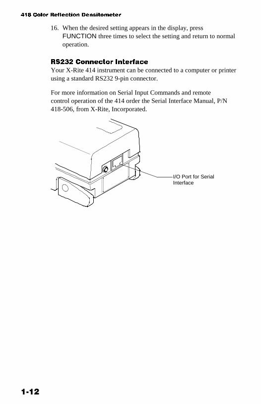
Your X-Rite 414 instrument can be connected to a computer or printerusing a standard RS232 9-pin connector.
For more information on Serial Input Commands and remotecontrol operation of the 414 order the Serial Interface Manual, P/N418-506, from X-Rite, Incorporated.
I/O Port for SerialInterface

���
��� ����������
Response Settings..................... 2-1Overview of CalibrationProcedures................................. 2-3Long Calibration ......................... 2-4Color Correlation (CC)Calibration .................................. 2-7Quick-Cal™................................2-9
���9���" �� ��������
Under long operating conditions, the instrument should be calibratedonce per week, or whenever the instrument displays a messageregarding calibration. You should perform a “long calibration”whenever possible. However, you can also perform a Quick-Cal™procedure any time after an initial long calibration has beenperformed.
Before calibrating, you should determine the appropriatedensitometer response setting for your instrument, based on yourproduction control requirements.
���%���� ����(�'�
A densitometer’s measurement system consists of several differentcomponents (lamp, optics, light sensor). Different densitometersconsist of different types of these components. The density readingsmeasured by these systems are called a densitometer response.Because components differ among densitometers, standard responseshave been established in the industry. These standards ensure thateven instruments with different components will measure inaccordance with the same response.
)�$������$ �� � ������ ��$���$�$
Using 414G optics, your 414 instrument can use the followingresponses:
• Status TANSI Status T Computerized Color Response iswideband response most typically used in the North Americangraphic arts industry. This status is used to calibrate theinstrument to the T-Ref™ color reference.
��� ����� ��� ��� ���� �� �
���
• Status GX-Rite Graphic Arts Response is a widebandresponse that is similar to Status T, except that it is moresensitive to denser yellow inks.
Using 414E optics, your 414 instrument can use the followingresponses:
• Status EEuropean utilizes the Wratten 47B filter—for higherreadings in yellowinstead of the Wratten 47 filter typicallyused in North America.
• Status I (displayed as Status N)Narrow Band GlassInterference Type Computerized Color response is computercorrected and designed for use with process inks on paper.Measurements other than process inks may producemeasurement data with slight discrepancies. NOTE: The 414displays this Status as Status N.
Using 414A optics, your 414 instrument can use the followingresponses:
• Status APhoto finishing application response.
�������+ ��$���$�
To select the appropriate response:
1. First, if this is your first time selecting response, you should plugyour instrument in using its AC adapter. This will prevent themicroprocessor from going into “sleep” mode to save batterypower. With the instrument plugged in, you’ll be free to takeyour time learning this procedure.
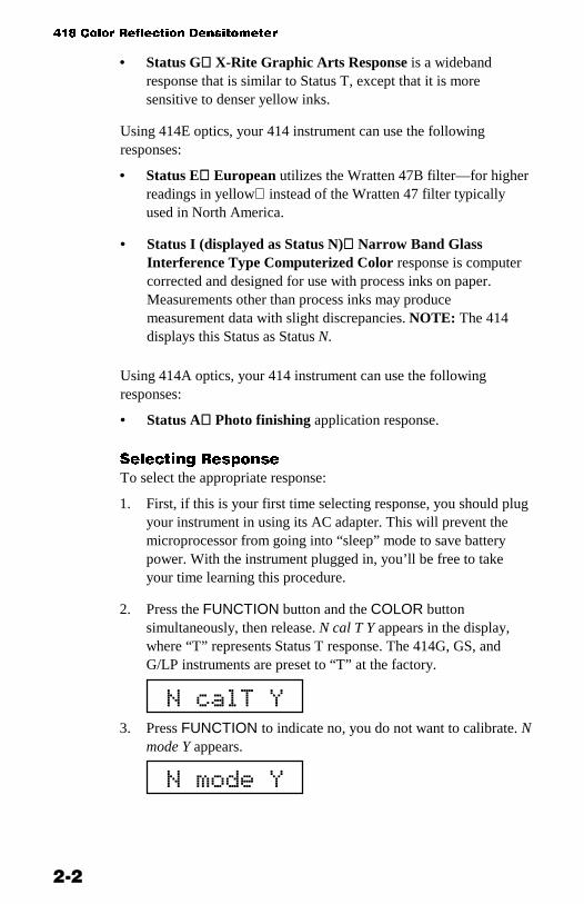
2. Press the FUNCTION button and the COLOR buttonsimultaneously, then release. N cal T Y appears in the display,where “T” represents Status T response. The 414G, GS, andG/LP instruments are preset to “T” at the factory.
3. Press FUNCTION to indicate no, you do not want to calibrate. Nmode Y appears.
��������
������

������� ���
���
4. Press ZERO to indicate yes, you want to enter modes. ↓ RESP T(or G or E) appears.
5. Press ZERO again, then again to toggle the Status selectionbetween T and G (for 414G), or E and N (for 414E). Stop whenthe desired response is displayed.
6. Press FUNCTION three times to return to the main display.
NOTE: Separate memory positions store calibration data foreach of the four responses. If you change optics or changeresponse setting, you must re-calibrate using that response.
You do not need to re-calibrate when you switch to a responsefor which you have already calibrated.
�-��-(�1 �� �/(.���(�� %�� �)����
Calibrating your instrument is crucial to maintaining its measurementstability. It is also important to maintaining measurement agreementbetween several densitometers at the same site and making alldensitometers calibrate precisely to the same standard reference, suchas T-Ref. Your 414 instrument’s Computerized Color Response™allows you to use one of three different calibration procedures toaddress these factors:
1. Long Calibration allows you to calibrate your instrument to anycolor reference. This procedure will be used before you takeyour first measurements for each response. After this calibrationprocedure has been performed, you can use Quick-Cal™ (seebelow) to quickly re-calibrate when necessary. If using a colorreference other than that provided by X-Rite, use long calibrationto recalibrate the unit.
2. Color Correlation Calibration allows you to set the 414 tomeasure in agreement with another densitometer that has thesame response (for example, two wideband densitometers).
3. Quick Cal™ allows you to quickly re-calibrate to white withouthaving to re-measure the black and/or color patches.
�������

��� ����� ��� ��� ���� �� �
���
/��' �/(.���(��
1. If this is your first time calibrating, you should plug yourinstrument in using its AC adapter. This will prevent themicroprocessor from going into “sleep” mode to save batterypower. With the instrument plugged in, you’ll be free to takeyour time learning this procedure.
2. Unlock the Shoe.
3. Press the FUNCTION and COLOR buttons simultaneously untilN cal T Y appears in the display. T stands for the default Status TResponse in the 414G, GS, and G/LP; if you have a differentresponse selected, its initial letter will appear in this position.(See “Selecting Response” earlier in this chapter.)
4. Press ZERO to indicate Yes, you do want to calibrate.
5. Press FUNCTION to select long calibration. SET LO appears inthe display for a moment.
6. At this point, refer to the front ofyour Color Reflection ReferenceEnvelope. (Figure 2-1)
The first value that appears in thedisplay should match the visual(“V”) value for the T Responseprinted on your envelope under:
STEP 1 (WHITE) CAL-LO
T V0.07 C0.06 M0.07 Y0.10G V0.07 C0.06 M0.07 Y0.10
NOTE: Values shown above andin Figure 2-1 are examplesyourvalues may be different.
���������
Figure 2-1
������
�� �!"!#�
���$�����

������� ���
���
7. If the values on the envelope and on the display do not match,enter the correct value using the blue and red arrow buttons.
To lower the value:Press and hold the ZERO (��) button, then press FUNCTION(�) repeatedly to lower the value until the correct value isshown.
To raise the value:Press and hold the ZERO (��) button, then press COLOR (�)repeatedly to raise the value until the correct value is shown.
TIP: If you need to move the value up or down by a largeamount, hold the (��) button and (�) or (�) button down. Thenumbers will advance faster as you hold it down.
8. Release all buttons, then press COLOR. The T Response valuefor cyan (C) appears. It should match the value printed on yourReference Envelope.
STEP 1 (WHITE) CAL-LO
T V0.07 C0.06 M0.07 Y0.10G V0.07 C0.06 M0.07 Y0.10
9. If the values on the envelope and on the display do not match,use the blue and red arrow buttons as specified in #7 to enter thecorrect value.
10. Follow #8 again for magenta (M), and then again for yellow (Y).If the envelope and display values do not match for either color,follow #7 to correct.
11. Press COLOR again. SET HI appears for a moment. Then,the Step 3 (Black) CAL HI value for the T Response appears.(Figure 2-1)
12. If the values on the envelope and on the display do not match,use the blue and red arrow buttons as specified in #7 to enter thecorrect value.
13. Repeat #11 for Step 4 (cyan), Step 5 (magenta), and Step 6(yellow). Follow #7 if you need to correct the values. (Figure 2-1)
����!"!%�
������ � ��"&��

��� ����� ��� ��� ���� �� �
���
14. Press COLOR again. READ WHT appears.
15. Take your Color Reflection Card out of the envelope. Lay it on aflat, steady surface with the color target side facing up. (Figure 2-2)
Figure 2-2
16. Read Step 1the white target patchby placing the instrumenttarget window cross-hairs over the alignment marks, thenlowering the head down onto the shoe. One of the filter valuesfor Step 1 appears in the display, then READ BLK (BLACK)appears.
17. Read Step 3the black target patch (not Step 2, the gray patch).One of the filter values for Step 3 appears in the display, thenREAD CYAN appears.
18. Repeat these measurement steps for Step 4 (cyan), Step 5(magenta), and Step 6 (yellow).
The values that appear for each Step measurement should matchthe values listed on the envelope for that Step. If they do not,repeat the calibration procedure. If discrepancies continue toexist, contact X-Rite Instrument Services.
If all values were correct, your instrument is calibrated!
If you wish to calibrate to make your instrument measure inagreement with another instrument, perform the followingprocedures for “Color Correlation Calibration.”
Color TargetPatches
Alignmentmarks
�����'��
�!"!%� �������(

������� ���
��
�/�� ����/��(�� : ; �/(.���(��
There are two ways to perform color correlation calibration, whichcreates measurement agreement between your 414 and another,similar instrument. The method you use depends on the type ofcalibration reference used by the other instrument.
NOTE: Color correlation between two instruments can best beachieved between two very similar instrumentstwo that utilize thesame status setting, have the same optics type, aperture size, andpolarization (both haveor both do not havepolarization filters).
If the other instrument uses a reference similar to the 414’swithblack, white, cyan, magenta, and yellow ink targets on paperthenuse the first set of instructions. If the other instrument uses areference without CMYK patchessuch as a ceramic plaque withwhite and black onlythen use the second set of instructions.
�$�+ !�$��� (�$������ !*& ���+��
1. Calibrate the other, “master” instrument according to itsmanufacturer’s specifications and instructions.
2. Begin a long calibration procedure for your 414 instrument (seeprevious section).
3. When you go to verify the calibration values on the calibrationreference envelope, use the values for the master instrument’scalibration standard instead. Use the procedure in #7 of the longcalibration instructions to modify the values on your instrumentdisplay to match those on the master instrument’s envelope orreference.
4. When calibration is due for either instrument, use the masterinstrument’s calibration reference.

��� ����� ��� ��� ���� �� �
��
2�� �� !�$��� (�$������ !*& ���+��
1. Get a pen or pencil and piece of paper ready.
2. Calibrate the master instrument according to its manufacturer’sspecifications and instructions.
3. Prepare the master instrument to read low density (whiteCAL LO).
4. Measure Step 1 (white) on the 414’s calibration reference usingthe master instrument. Write down the low density values forvisual, cyan, magenta, and yellow.
5. Prepare the master instrument to read high density (blackCAL HI).
6. Measure Step 3 (black) on the 414’s calibration reference usingthe master instrument. Write down the high density values forvisual, cyan, magenta, and yellow.
7. Prepare the master instrument to read color patches.
8. Read Steps 4, 5, and 6 (cyan, magenta, and yellow) on the 414’scalibration reference using the master instrument. Write down thedensity values for each color.
9. Begin a long calibration using your 414 instrument. When yougo to set the CAL LO values, verify the visual, cyan, magenta,and yellow values against the low density values you measuredwith the master instrument. Use the arrow buttons to adjust thevalues (see #7 of the last section).
10. Press COLOR again to advance to setting the CAL HI values.Verify the visual, cyan, magenta, and yellow values against thehigh density values you measured with the master instrument.Use the arrow buttons to adjust the values (see #7 of the lastsection).
11. When you enter the last CAL HI value, the instrument recognizesthat you have entered measured black values for each color filter.N col↑↓ Y appears in the display, asking if you wish to performa color correlation calibration.
12. Press ZERO to indicate yes, you do want to perform a colorcorrelation calibration (or FUNCTION if you do not want toreadjust the color correlation).

������� ���
���
13. SET COLOR VALUES appears briefly in the display, followedby the CAL HI value for cyan. Verify the cyan value against thecyan value you measured with the master instrument. Use thearrow buttons to adjust the value (see #7 of the last section).
14. Verify the magenta and yellow values against the valuesmeasured with the master instrument, then adjust the values tomatch the master values as necessary.
15. READ WHT appears in the display. Measure white, then verifythat the value matches the values recorded for each masterinstrument measurement. The display prompts you to measureSteps 3, 4, 5, and 6. Verify that these values match the masterinstrument’s measurements, as well.
16. Perform future calibrations of your 414 using this procedure.
��( & �/�
Once you have performed the long calibration, you can simplyperform the Quick Cal™ procedure periodically to set the lowdensity (white) value.
NOTE: In most cases, you should simply perform an entire longcalibration if possible.
1. Press FUNCTION and COLOR simultaneously, then release. Ncal T Y appears in the display. T stands for the default Status TResponse; if you have a different response selected, its initialletter will appear in this position. (See “Selecting Response”earlier in this chapter.)
2. Press ZERO to indicate yes, you do want to calibrate.
3. Press ZERO to select Quick Cal™ procedure.
4. Read Step 1the white patchon the reference card.
Your instrument is calibrated!

��� ����� ��� ��� ���� �� �
����

���
��� �������
� �����
Selecting Density Function......... 3-2Selecting Density Mode ............. 3-2Selecting Color MeasurementMethod ....................................... 3-4Density Measurement ................ 3-6Density DifferenceMeasurement ............................. 3-8
For density measurement, you need to set some measurementparameters. You need to select:
• the desired measurement function (density) (page 3-2);• the desired density measurement modeabsolute density,
density minus paper, or density non-heat mode (page 3-3); and• the desired color measurement methodSINGLE, AUTO, 3
COLOR or ALL (page 3-4).
These parameters must be set for all types of density measurement.Once these parameters are set, you can set your instrument toevaluate measurement data two different ways:
• As a straight density measurement data. Viewing this datarequires no additional setup (page 3-6).
or• As a density difference measurement data. This data shows you
the amount of difference between the measured density and apre-set reference density. To view data in this format, you needto establish a reference measurement, and set up the instrumentfor density difference readings (page 3-9).

��� ����� ��� ��� ���� �� �
���
��/� �(�' )���(�* ��� �(��
1. If this is your first time selecting a measurement function andmode, you should plug your instrument in using its AC adapter.This will prevent the microprocessor from going into “sleep”mode to save battery power. With the instrument plugged in,you’ll be free to take your time learning this procedure.
2. Next, make sure you have the desired response setting selected,and that the instrument is properly calibrated. These proceduresare covered in chapter 2, “Calibration.”
3. To select the measurement method for measuring ink density,press the FUNCTION button repeatedly until DEN appears inthe display.
Now, you can choose to measure absolute density which reads the inkdensity including the paper, density minus paper, or density nonheat,which subtracts paper from 3C. You make this selection by settingdensity mode.
��/� �(�' )���(�* !�)�
1. Press the FUNCTION button and the COLOR buttonsimultaneously, then release. N cal T Y appears in the display,where “T” represents Status response you selected (T, G, E, N, A).
2. Press FUNCTION to indicate no, you do not want to calibrate.N mode Y appears in the display.
3. Press ZERO to indicate yes, you do want to set mode. ↓ RESP Tappears in the display.
4. Press FUNCTION to advance to mode selection. DENABSOLUTE, DEN –PAPER, or DEN NONHEAT appears in thedisplay.
���
���������
�������
� �������
������������

���� � ���� ����
���
5. Here is where you select density minus paper, absolute density,or nonheat.
If you wish to select density minus paper, press ZERO untilDEN-PAPER appears in the display. Then, simply pressFUNCTION until you exit mode selection. Density minus papermode is already selected; DEN-PAPER appears in the displaybriefly, followed by READ PAPER.
If you wish to select absolute density, press ZERO until DENABSOLUTE appears in the display. Then, simply pressFUNCTION until you exit mode selection. Absolute densitymode is already selected; DEN ABSOLUTE appears in thedisplay briefly, followed by a color value for visual, cyan,magenta, or yellow.
If you wish to select nonheat, press ZERO until DENNONHEAT appears in the display. Then press FUNCTION untilyou exit mode selection.
Measurement mode is now selected. Absolute densitymeasurement data will appear with a “D” after the value; densityminus paper data will appear with an underlined “D”.
!��$��+ %���� ��� )���% !�#�
When you select density minus paper as the measurement mode, youmust provide a reading of the paper before taking colormeasurements. The instrument will take the density value of thepaper and automatically subtract it from subsequent colormeasurements. This paper value must be updated before everymeasurement sequence.
Once density minus paper (DEN-PAPER) mode is selected, READPAPER appears in the display. Center the instrument target windowover a sample of the paper, then lower the instrument head to take areading and hold.
����������
) �!"�*+) �!"�*�
Indicates absolutedensity
Indicates densityminus paper

��� ����� ��� ��� ���� �� �
���
• If the instrument recognizes the measurement as a paper reading,the display becomes ready for the first color reading.
• If the instrument does not recognize the measurement as a paperreading, IF PAPER PRESS Z appears.
Keep the instrument pressed down, then press ZERO to indicatethat yes, this is the new paper value. Then, the display becomesready for the first color reading.
��/� �(�' �/�� !������!��� !��0�)
You can choose from four different measurement methods using thedensity function:
• SINGLE measurement method simply measures and updates thespecific color you selected.
• AUTO measurement method measures v, c, m, y, r, g, b, andbalance, then simply updates and displays the most dominantcolor.
• 3 COLOR measurement method measures and updates all threecolors and displays cyan, magenta, and yellow together. 3 Colorcan also be displayed as Balance, which subtracts the two lowestdensities of c, m, or y from the highest and displays those twocolors as the amount of density required to make them equal tothe highest. If Balance –Ref is enabled, the reference values aresubtracted before the balance subtractions.
• ALL COLOR measurement method measures and updates c, m,and y, and displays them at the same time. (Black can bedisplayed by pressing COLOR when the head is up. If a blackink was measured, the display automatically displays black.)
NOTE: There is no 3 COLOR or ALL COLOR for DOT. Grayness isonly AUTO.
To select color measurement method:
1. Press FUNCTION until DEN appears in the display. After amoment, the CAL LO value for one of the colorsvisual (v),cyan (c), magenta (m), or yellow (y)appears in the display.
�,�������������-
�!"�*+
) �!"�*+
���� � ���� ����
���
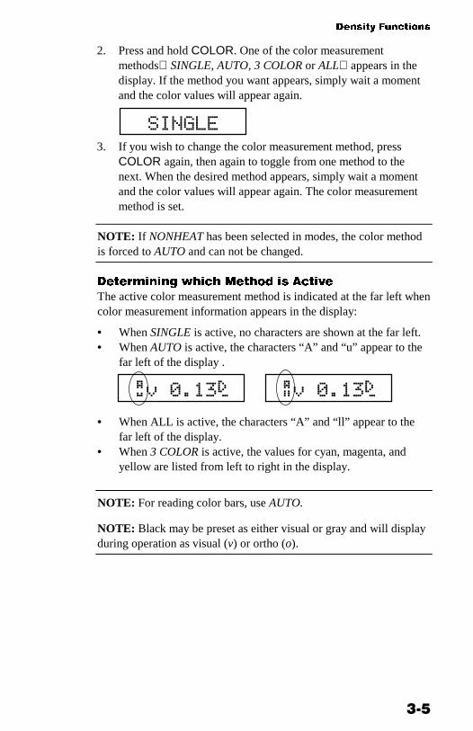
2. Press and hold COLOR. One of the color measurementmethodsSINGLE, AUTO, 3 COLOR or ALLappears in thedisplay. If the method you want appears, simply wait a momentand the color values will appear again.
3. If you wish to change the color measurement method, pressCOLOR again, then again to toggle from one method to thenext. When the desired method appears, simply wait a momentand the color values will appear again. The color measurementmethod is set.
NOTE: If NONHEAT has been selected in modes, the color methodis forced to AUTO and can not be changed.
)�������+ 2��� !����# $ ��� �
The active color measurement method is indicated at the far left whencolor measurement information appears in the display:
• When SINGLE is active, no characters are shown at the far left.• When AUTO is active, the characters “A” and “u” appear to the
far left of the display .
• When ALL is active, the characters “A” and “ll” appear to thefar left of the display.
• When 3 COLOR is active, the values for cyan, magenta, andyellow are listed from left to right in the display.
NOTE: For reading color bars, use AUTO.
NOTE: Black may be preset as either visual or gray and will displayduring operation as visual (v) or ortho (o).
���.��
/ �!"�*+ ) �!"�*+

��� ����� ��� ��� ���� �� �
���
)���(�* !������!���
So far, you have performed the procedures to select density function,mode, and color measurement method.
You are now ready to begin taking measurements to check densityvalues on your press sheet color bar. The type of measurement datathat will be displayed will depend on the way you set up yourinstrument earlier in this chapter. However, for all functions, modes,and methods, the measurement technique is the same. Simply:
1. Center target window over area to be measured.
2. Lower unit to target window and hold closed.
3. Once measurement data is displayed, release the unit.
4. Measurement data will appear either as a normal density value(absolute or minus paper) or difference value.
-�2�+ )��$�" !��$������ )���
There are several different combinations of mode and methodsettings that will affect the way the measurement data is displayed.Since you just set up these parameters yourself, you should see thedata in the format you expect. For example, if you set your instrumentparameters to AUTO and -PAPER, your measurement data willappear like this:
“A” and “u” appear to the far left, indicating that the instrumentautomatically recognized the colorin our example, the color wascyan. And, the “D” after the value is underlined for density minuspaper measurements or not underlined for absolute densitymeasurements.
/���"�*+

���� � ���� ����
��
-�2�+ !��$������ )��� ��� ���� ����
You can view measurement data in the display for one color at atime. To toggle the display view from one color’s measurement datato the next, press the COLOR button when data is displayed. Eachtime you press, the display switches from visual to cyan to magenta,and so forth.
If you are using the SINGLE or AUTO measurement method, thedata displayed for each color represents the last time that color wasmeasured. If you are using the ALL method, each color’s datarepresents the amount of that color measured in the last color read.The most dominant color will have the highest density reading.
/ ��"�*+
/���"�#+
/���"�0+
/1��"!�+
EXAMPLE: Pressing the COLORbutton repeatedly toggles displayfrom one color’s measurement datato the next.
) �!"%#�
)��!"�!�
)���"�*�
)1�!"##�
EXAMPLE: Using the ALLmeasurement method, all color data isderived from the single most recentmeasurement. In our example,magenta is the most dominant color.

��� ����� ��� ��� ���� �� �
��
)���(�* )(������ � !������!���
Density difference measurement uses the same parameters as densitymeasurement. To set up for density difference measurement, followthe procedures earlier in this chapter for selecting density function,mode, and color measurement method.
To view measurement data as a density difference value between ameasured sample and a known referenceinstead of the densityvalue of the measured sampleyou must first enter a referencemeasurement; and then activate the density difference (DEN-REF orDEN-PAPER-REF) display format.
������+ � ��������� !��$������
1. Press FUNCTION until DEN appears in the display. After amoment, a color value for one of the colors appears in thedisplay.
2. Press ZERO. REF appears for a moment, followed by thecurrent Reference value. If none has been entered, the Referencevalue is 0.00.
3. To enter a reference valueor change the current referencevalueyou can either:measure the reference value directly; ormanually enter the reference value using the arrow buttonfunctions.
To measure the reference value directly:
Measure the color that you wish to use as the reference. Then,press FUNCTION to return to normal operation.
To enter the reference value manually:
Hold down the ZERO (��) button, then press the FUNCTION(▼) or CAL (▲) button to adjust the value until the desired valueis shown. Then, press FUNCTION to return to normal operation.
TIP: If you need to move the value up or down by a largeamount, hold the arrow button down. The numbers will advancefaster as you hold it down.
���� � ���� ����
���
��� ���+ )��$�" )�������� )$���" ������
Once you have your reference measurement established and stored inthe instrument’s memory, you now simply need to activate the densitydifference display format:
1. When you press FUNCTION and DEN or DEN-PAPER appears,press ZERO before the display switches to READ PAPER or thefirst color value. -REF is added to the function. The displayreads as either DEN-REF if you are in absolute mode; or DEN-PAPER-REF if you are in minus paper mode.
2. To de-activate density difference display format, repeat #1 toremove -REF from the function.
-�2�+ )��$�" )�������� !��$������ )���
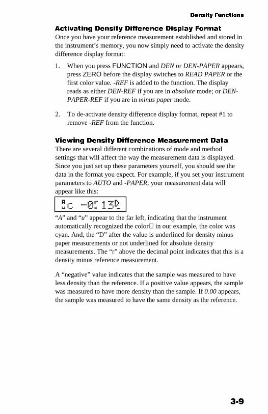
There are several different combinations of mode and methodsettings that will affect the way the measurement data is displayed.Since you just set up these parameters yourself, you should see thedata in the format you expect. For example, if you set your instrumentparameters to AUTO and -PAPER, your measurement data willappear like this:
“A” and “u” appear to the far left, indicating that the instrumentautomatically recognized the colorin our example, the color wascyan. And, the “D” after the value is underlined for density minuspaper measurements or not underlined for absolute densitymeasurements. The “r” above the decimal point indicates that this is adensity minus reference measurement.
A “negative” value indicates that the sample was measured to haveless density than the reference. If a positive value appears, the samplewas measured to have more density than the sample. If 0.00 appears,the sample was measured to have the same density as the reference.
/��2!3�*+

��� ����� ��� ��� ���� �� �
����

���
��� ����� �����
Selecting Dot Area or Dot Gain.. 4-2Selecting Measurement Method 4-3Dot Area Function ...................... 4-4Dot Gain Function ...................... 4-5
The 414 G & E units allow dot area and dot gain measurements. Fordot measurements, you need to set some measurement parameters.You need to select:
• the desired measurement functiondot area or dot gain(page 5-3); and
• the desired color measurement methodSINGLE or AUTO(page 5-4)
• NOTE: All dot function measurements are minus paper.
Dot is calculated using the Murray-Davies or Yule-Nielson formula.The Murray-Davies simply calculates dot by comparing the densityof the tint minus paper with the density of the solid minus paper.
The Yule-Nielson formula allows you to compensate for the amountof reflected light (absorbed and trapped) lost when taking a dotmeasurement. This can be accomplished by changing the ‘n’ factor(refer to page 4-2).
When using the Murray-Davies formula a % displays; when the Yule-Nielson formula is used a Y/N displays.

��� ����� ��� ��� ���� �� �
���
The Murray-Davies formula for calculating Dot is:
Apparent Dot Area = ( )
( )1-10
1-10x100
- D
- D
t
s
The Yule-Nielson formula for calculating Dot is:
% Dot = 1 – 10-(Dt/n) x100
1 – 10-(Ds/n)
Where: Dt = Density of tint minus density of paperDs = Density of solid minus density of paper
Listed below are approximate ‘n’ factors for some commonly usedmaterials:
Material Factor
Uncoated Paper 2.7
Coated Paper 1.6-1.7
3M Transfer Key 1.9
DuPont Cromalin 2.6
3M Color Key 4.0
Agfa Gevaert Gevaproof 1.4
Newsprint 2.5
��/� �(�' )�� ���� �� )�� '�(�
1. If this is your first time selecting a measurement function, youshould plug your instrument in using its AC adapter. Thisprevents the microprocessor from going into “sleep” mode tosave battery power. With the instrument plugged in, you’ll befree to take your time learning this procedure.
2. Next, make sure you have the desired response setting selected,and that the instrument is properly calibrated. These proceduresare covered in chapter 2, “Calibration.”
3. To select the measurement method for measuring ink density,press the FUNCTION button repeatedly until DOT AREA orDOT GAIN appears in the display.
�������� ����.���

�� ���� ����
���
4. If DOT AREA appears and you wish to select DOT GAIN, pressand release the ZERO button to toggle the selection. Do thesame if DOT GAIN appears and you wish to select DOT AREA.
��/� �(�' �/�� !������!��� !��0�)
You can choose from three different measurement methods using thedot function:
• SINGLE measurement method simply measures and updates thespecific color you selected.
• AUTO measurement method measures all four colors, thensimply updates and displays the most dominant color.
• 3 COLOR measurement method measures and updates all threecolors and displays cyan, magenta, and yellow together.
NOTE: ALL is not used for dot measurements.
To select color measurement method:
1. Press FUNCTION until DOT AREA or DOT GAIN appears inthe display. After a moment, READ PAPER appears in thedisplay.
2. Press ZERO. A dot area or dot gain value for one of thecolorsvisual (v), cyan (c), magenta (m), or yellow (y)appearsin the display.
3. Press and hold COLOR. One of the color measurement methodsappears in the display. If the method you want appears, simplywait a moment and the color values will appear again.
3. If you wish to change the color measurement method, pressCOLOR again, then again to toggle from one method to thenext. When the desired method appears, simply wait a momentand the color values will appear again.
Color measurement method is set.
)�������+ 2��� !����# $ ��� �
The active color measurement method is indicated at the far left whencolor measurement information appears in the display:
/���!!�4
���.��

��� ����� ��� ��� ���� �� �
���
• When SINGLE is active, no characters are shown at the far left.• When 3 COLOR is active, cyan, magenta, and yellow are
displayed from left to right.• When AUTO is active, the characters “A” and “u” appear to the
far left of the display.
)�� ���� ��� �(��
Once dot area measurement (DOT AREA) mode is selected, READPAPER appears in the display.
1. Center the instrument target window over a sample of the paper,then lower the instrument head to take a reading and hold.
If the instrument recognizes the measurement as a paperreading, the display flashes DOT T (or DOT G, or DOT E, and soforth) momentarily, then becomes ready to READ SOLID.If the instrument does not recognize the measurement as apaper reading, IF PAPER PRESS Z appears.
Keep the instrument pressed down, then press ZERO to indicatethat yes, this is the new paper value. Then, the display becomesready to READ SOLID.
2. Measure the solid patch. DOT T is displayed duringmeasurement, then the measurement data appears.
If Solid is displayed as a dot value (a percentage, such as m94%) instead of a solid density value (such as m 1.57s), hold theinstrument closed and press ZERO.
In the event that IF SOLID PRESS Z is displayed, press ZEROto measure as a solid, then release the instrument.
NOTE: Solid density is displayed minus paper.
����������
�,�������������-
/ �!"�*+
/����������
����� /���"5#�

�� ���� ����
���
3. Read a tint of the solid color you just measured. Duringmeasurement, DOT T is displayed. Then, the dot value isdisplayed.
4. Measure additional tints of that color. The instrumentautomatically recognizes the measurements as tint values anddisplays the tint percentage.
5. When you are ready to measure another color, simply measurethe solid and repeat the procedures beginning with #2. Theinstrument automatically recognizes the measurement as a solid.Also, you do not need to enter a new paper measurement.
)�� '�(� ��� �(��
Dot gain measurement compares the tint percentage of a color patchon paper to the intended tint percentage produced on the film.
Your instrument is preset at the factory to use the standard tintpercentages for color bar patches as the four measurementreference values:
Factory presets for 414G & T Factory presets for 414E & NReference 1 (r1) is 25% Reference 1 (r1) is 40%Reference 2 (r2) is 50% Reference 2 (r2) is OFF—Reference 3 (r3) is 75% Reference 3 (r3) is 80%
Your first dot gain measurement compares the dot percentage of themeasured patch to the first reference value (r1). The differencebetween the reference value and the measured value is calculated asdot gain the amount the ink dots have spread on the paper.
If needed, you can adjust the Reference values to meet your specificneeds. These procedures are covered next. If you wish to simply usethe factory preset reference values, you can skip ahead to “Dot GainMeasurement.”
�#<$��+ )�� '�� ��������� -���$
Once dot gain measurement (DOT GAIN) mode is selected, PAPERappears in the display.
�����
����� /��#5�4

��� ����� ��� ��� ���� �� �
���
1. Press ZERO two times. REF appears in the display momentarily,followed by one of the reference valueseither r1, r2, or r3.
2. To select the desired color at the current reference value, pressCOLOR to toggle between v, c, m, and y. The factory presetsshould show the same value for each color. (You can enter adifferent value for each color if you like.)
3. When the color and reference value you wish to change appear inthe display, use the ZERO (▼▲), COLOR (▲), andFUNCTION (▼) buttons to adjust the value.
Press and hold ZERO, then press COLOR (▲) to raise thevalue;Press and hold ZERO, then press FUNCTION (▼) to lowerthe value.
When you change the preset values, they are turned “off.” Yournew reference values can be set within the following ranges.
r1 can be set between 1% and 45%.—r2 can be set between 46% and 64%r3 can be set between 65% and 100%
4. Advance to the next color, then repeat #3; or press ZERO toadvance to the next reference value, either r1, r2, or r3.
Repeat #3 and #4 until all reference values are set to yourpreferences.
5. Press FUNCTION to return to dot gain measurement mode.Measurements at each tint will be compared to the appropriatereference value.
6 ��#5�7
��, 6 ��5!�8
“R2” character indicatesReference 2 value
Indicates color

�� ���� ����
��
)�� '�� !��$������
Once dot gain measurement (DOT GAIN) mode is selected, READPAPER appears in the display.
1. Center the instrument target window over a sample of the paper,then lower the instrument head to take a reading and hold.
If the instrument recognizes the measurement as a paperreading, the display flashes DOT T (or DOT G, or DOT E, and soforth) momentarily, then becomes ready to READ SOLID.If the instrument does not recognize the measurement as apaper reading, IF PAPER PRESS Z appears.
Keep the instrument pressed down, then press ZERO to indicatethat yes, this is the new paper value. Then, the display becomesready to READ SOLID.
2. Measure the solid patch. DOT T is displayed duringmeasurement, then the measurement data appears.
If Solid is displayed as a dot value (a percentage, such as m94%) instead of a solid density value (such as m 1.57s), hold theinstrument closed and press ZERO.
In the event that IF SOLID PRESS Z is displayed, press ZEROto measure as a Solid, then release the instrument.
NOTE: Solid density is displayed minus paper.
3. Read the first tint of the solid color you just measured. Thisshould be the color patch with the lowest tint percentage, such asthe 25% patch. During measurement, DOT T is displayed. Then,the Dot Gain value is displayed.
����������
�,�������������-
/����������
����� /���"5#�
����� /���59�4
Mark indicates 1st tint measured

��� ����� ��� ��� ���� �� �
��
A mark before the percentage symbol indicates which tintpercentage in the sequence has been measured.
4. Measure the remaining tints of that color. The instrumentautomatically recognizes the measurements as tint values anddisplays the dot gain value for that tint. Display marks indicatewhich tint percentage in the sequence has been measured.
/��5!99�4 /��#5999�4
2nd dot gain measurement 3rd measurement

���
��� ������������������
Formulas .................................... 5-1Selecting Grayness Function ..... 5-1Selecting Grayness Mode.......... 5-2Grayness Measurement............. 5-4
For grayness measurements, you need to set some measurementparameters. You need to select:
• the desired measurement function (grayness) (page 8-2); and• the desired measurement modeabsolute grayness, or grayness
minus paper (page 8-3).• NOTE: All grayness function measurements are AUTO only.
���!�/��
Grayness percentage is calculated as follows:
G =D
DL
H
×100
Where:
• DH = Highest density of R, G, or B-P• DL = Lowest density of R, G, or B-P
��/� �(�' '��*���� ��� �(��
1. If this is your first time selecting a measurement function, youshould plug your instrument in using its AC adapter. This willprevent the microprocessor from going into “sleep” mode to savebattery power. With the instrument plugged in, you’ll be free totake your time learning this procedure.
2. Next, make sure you have the desired response setting selected,and that the instrument is properly calibrated. These proceduresare covered in the chapter 2, “Calibration.”

��� ����� ��� ��� ���� �� �
���
3. To select the measurement method for measuring grayness, pressthe FUNCTION button repeatedly until GRAYNESS appears inthe display.
Now, you can choose to measure absolute grayness, which will readthe grayness including the paper; or to measure grayness minuspaper. You make this selection by setting grayness mode.
��/� �(�' '��*���� !�)�
1. Press the FUNCTION button and the COLOR buttonsimultaneously, then release. N cal T Y appears in the display,where “T” represents Status response you selected (T, G, E, orN).
2. Press FUNCTION to indicate no, you do not want to calibrate.N mode Y appears in the display.
3. Press ZERO to indicate yes, you do want to set mode. ↓ RESP Tappears in the display.
4. Press FUNCTION to advance to mode selection. GRAYNESS-PAPER or GRAYNESS appears in the display.
5. Here is where you select grayness minus paper or absolutegrayness.
If you wish to select grayness minus paper, press ZERO untilGRAYNESS-PAPER appears in the display. Then, simply pressFUNCTION until you exit mode selection. Minus paper mode isalready selected; GRAYNESS-PAPER appears in the displaybriefly, followed by READ PAPER.
If you wish to select absolute grayness, press ZERO untilGRAYNESS appears in the display. Then, simply pressFUNCTION until you exit mode selection. Absolute mode is
.�������
���������
�������
� �������
.�������

�������� ������ ���
���
already selected; GRAYNESS appears in the display briefly,followed by a grayness value.
Measurement mode is now selected. Grayness measurement datawill appear with a “G” after the value; minus paper data isindicated by an underlined letter “G” .
!��$��+ %�%�� ��� '��"��$$
When measuring grayness minus paper, you must provide a readingof the paper before taking color measurements. The instrument willtake the value of the paper and automatically subtract it fromsubsequent color measurements. This paper value must be updatedbefore every measurement sequence.
Once GRAYNESS-PAPER appears in the display. Center theinstrument target window over a sample of the paper, then lower theinstrument head to take a reading and hold.
• If the instrument recognizes the measurement as a paper reading,the display becomes ready for the first color reading.
• If the instrument does not recognize the measurement as a paperreading, IF PAPER PRESS Z appears.
Keep the instrument pressed down, then press ZERO to indicatethat yes, this is the new paper value. Then, the display becomesready for the first color reading.
����������
�,�������������-
��5�"&.�
�
Indicates absolutegrayness
Indicates graynessminus paper
��5�"&.�
� ��5�"&.�
��

��� ����� ��� ��� ���� �� �
���
'��*���� !������!���
You are now ready to begin taking measurements to check your presssheet color bar. The type of measurement data that will be displayedwill depend on the way you set up your instrument earlier in thischapter.
However, for all functions, modes, and methods, the measurementtechnique is the same. Simply:
1. Center target window over area to be measured.
2. Lower unit to target window and hold closed.
3. Once measurement data is displayed, release the unit.
4. Measurement data will appear either as a normal grayness value(absolute or minus paper).
-�2�+ '��"��$$ !��$������ )���
Grayness value color is displayed as color over color at the far left—v (visual), c (cyan), m (magenta), y (yellow)—followed by thegrayness value and mode designation.
For example, “c” above “m” appearing to the far left, indicates thatthe color is cyan towards magenta. And, the “G” indicates it is agrayness value (underlined for grayness minus paper measurementsor not underlined for absolute grayness).
��5%"!.�
�

���
��� ������������ ��!�����
Serial Interface Information........ 6-1Instrument Specifications........... 6-4Accessories................................ 6-6General Cleaning ....................... 6-7Optics Maintenance ................... 6-7Target Window Replacement .... 6-8Lamp Replacement.................... 6-9
���(�/ (������ � (����!��(��
The connector used for serial input/output is a Modular 10 circuittype. Figure 6-1 is the connection diagram.
Figure 6-1
414

��� ����� ��� ��� ���� �� �
���
An RS232 modular interface adapter is available from X-Rite whichperforms as shown in the diagram on the previous page. This adapteralso provides a jack for the AC adapter so that only one cable needbe connected to the 414. Also, when the adapter is not connected tothe jack, the +V CHARGER is connected to pin 9 of the DB25 in thediagram. The charger ground is connected to the jack ground only.
The part numbers for these interface adapters are: P/N 418-70 (maleDB25 connector) or P/N 418-71 (female DB25 connector). See“Accessories” later in this chapter for other adapters.
A 10-foot modular to modular cable for connection of the 414 to theinterface adapter is available by ordering P/N SE108-69.
���� )������$
Pin 2 Transmitted Data: Data transmitted from the densitometerwith parameters (baud rate, format) set by the densitometer.
Pin 3 Received Data: Data received by the densitometer fromoutside source using the same parameters as the densitometer.
Pin 4 DTR (Data Terminal Ready): Logic 0 active (On Line) andLogic 1 during: Power Off, Power Up, Self Test, duringmeasurements, and when serving RCI.
Pin 5 is ignored.
Pin 7: This pin is used for supplying 12VDC @ 700ma for chargingthe 414 without having the Adapter connected directly to the unit.
(��� ��������$��$
Logic 1 = +.8VDC to -25VDCLogic 0 = +2.25VDC to +25VDC
���� ��������$��$
Logic 1 = approximately -4VDCLogic 0 = approximately +5VDC
Outputs are @ 0VDC during Power Down.
�������� ������ ���
���
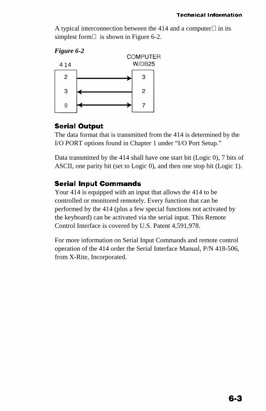
A typical interconnection between the 414 and a computerin itssimplest form is shown in Figure 6-2.
Figure 6-2
144
����� ����
The data format that is transmitted from the 414 is determined by theI/O PORT options found in Chapter 1 under “I/O Port Setup.”
Data transmitted by the 414 shall have one start bit (Logic 0), 7 bits ofASCII, one parity bit (set to Logic 0), and then one stop bit (Logic 1).
����� (��� �����#$
Your 414 is equipped with an input that allows the 414 to becontrolled or monitored remotely. Every function that can beperformed by the 414 (plus a few special functions not activated bythe keyboard) can be activated via the serial input. This RemoteControl Interface is covered by U.S. Patent 4,591,978.
For more information on Serial Input Commands and remote controloperation of the 414 order the Serial Interface Manual, P/N 418-506,from X-Rite, Incorporated.

��� ����� ��� ��� ���� �� �
���
(�����!��� �%� (�( ��(���
)$���"
Dot Matrix LCD
!��$��+ '������"
ANSI PH 2.17/DIN 16536 multi-sensor array
/+�� �����
Filament bulb 3000°K DIN approx. 2856°K ANSI
���� ��
Silicon Photodiode
���� ��$���$�
A optics with Status A Response
G optics for X-Rite Graphics Art Response w/ ANSI Status TComputerized Color ResponseTM
E optics w/47B per DIN16536 w/Glass interference typeComputerized Color ResponseTM
!��$��+ ���+�
0.00D-2.5D for A, G, & E0.00D-2.20D for GS, ES, G/LP, & E/LP0-100% dot [excluding A]
�����#����"
±0.01D±1% for dot area (10-100%) [excluding A]
/�����"
±0.01D or ±1%
(�����(�$������ �+�������
±0.02D or ±2%
������� )������
414A, G, E3.4mm414GS, ES1.7mm
��������
Automatic with Quick Cal™Adjusts Zero and Slope for DensityComputerized Color Response™ [excluding A]
�������� ������ ���
���
%����=���� �����
2 x linear /LP option [excluding A]
1��� �� ���
None
>��� ������"
±.01D maximum per 8 hours
����� ������"
±1% maximum per year
%�2�� ����"
Six rechargeable AA NiCad batteries 7.2v total rated @600mAh(included)
���+� ���
Approximately 14 hours
� �#����� ��9������$
414 90-130VAC, 50-60Hz, 15W Maximum414X 180-260VAC, 50-60Hz, 15W Maximum12VDC @ 700ma, Positive tip
�������+ ���������� ���+�
50°-104°F /10°-40°C
!��$������$ %�� ���+�
Approx. 4500 (usage dependent)
!��$��+ ���
Approximately 0.6 seconds
1�+��
800 grams
)���$��$
7.4cm H x 8.cm W x 19.6cm L

��� ����� ��� ��� ���� �� �
���
� �����(��
����$$���$ (���#�#
Color Reflection ReferenceOperation ManualAC AdapterCarrying Case
Specifications and design subject to change without notice.
����$$���$ ��# ����������� %���$ � ������
Polarization Filter.............................................................P/N 418-73 (includes 418/LP-62)Security Cable ..................................................................P/N 418-751.7mm Target Window......................................P/N 418-21-017-KIT3.4mm Target Window......................................P/N 418-21-034-KIT1.7mm Aperture........................................................ P/N 418-63-0173.4mm Aperture........................................................ P/N 418-63-034Lamp Assembly................................................................P/N 418-13A Optics ........................................................................P/N 404A-35G Optics ........................................................................P/N 418G-35G/LP Optics............................................................. P/N 418G/LP-35GS Optics ....................................................................P/N 418GS-35E Optics......................................................................... P/N 418E-35E/LP Optics ..............................................................P/N 418E/LP-35ES Optics..................................................................... P/N 418ES-35Modular Interconnect Cable........................................ P/N SE108-69DB25P DCE (Null Modem) Interface Adapter ................P/N 418-70DB25S DCE (Null Modem) Interface Adapter ................P/N 418-71DB25P DTE (Normal) Interface Adapter ........................P/N 418-80DB25S DTE (Normal) Interface Adapter.........................P/N 418-81DB9P Interface Adapter ...................................................P/N 418-90DB9S Interface Adapter ...................................................P/N 418-91Modular Interconnect Cable for Macintosh® computerswith 8 pin mini-DIN connector.........................................P/N 418-79
For further information on accessories contact your X-Riterepresentative or call X-Rite, Inc. at: 1-888-826-3059.

�������� ������ ���
��
'�����/ /���(�'
The exterior of the instrument can be wiped clean with a clothdampened in water or a mild cleaner whenever required.
NOTE: Do not use any solvents to remove ink from the cover.
�%�( � !�(������ �
1. Remove Optics assembly by removing sensor nose screws fromdensitometer housing, and then lifting the assembly upward.(Figure 6-3)
Figure 6-3
2. Remove three inner screws [1] on sensor nose [2] and rotateOptics over carefully so sensor nose [2] is at bottom.
3. Carefully lift up Optics assembly [4] separating from sensor nose[2].
4. Clean Optics sensors with camelhair brush and set aside.
5. Carefully remove IR Glass [3] and optional polarizing filter (ifinstalled) from sensor nose [2].
6. Remove dust and lint from inner sensor nose and filter(s) withcamelhair brush.
5
4
3
2
1

414 Color Reflection Densitometer
66--88
7. Carefully reinstall optional polarizing filter (if used) and IR Glass [3] (holding both by edges) into sensor nose, making sure filter(s) are properly seated.
8. Align flat edge of sensor nose [2] with flat edge on Lamp assembly PCB [5] and secure sensor nose [2] to Optics assembly [4] with three inner screws [1].
9. Carefully reinstall Optics assembly into densitometer by facing flat edge of sensor nose to front of densitometer. Work into position until alignment pins and connector pins are properly seated.
10. Insert and tighten sensor nose screws.
TARGET WINDOW REPLACEMENT
1. Remove old target window by pushing downward on top of shoe [1]. Clean off any remaining adhesive from shoe. (Figure 6-4)
Figure 6-4
2. Turn densitometer over and compress shoe [1] all the way down, and lock shoe.
4 2
1
3

Technical Information
66--99
3. Remove paper backing from tape strip on new target window [2], and remove clear film from opposite side of new target window.
4. Place one taped edge of target window [2] on indent [4] at bottom of shoe [1].
5. Align hole of target window [2] exactly in center of hole in sensor nose [3] and press remaining three sides of target window into place.
6. Unlock shoe.
LAMP REPLACEMENT
Lamp Removal 1. Remove Optics assembly by removing sensor nose screws [1]
from the densitometer housing, and then lifting assembly upward. THE THREE INNER SCREWS ON SENSOR NOSE ARE NOT TO BE REMOVED. (Figure 6-5)
Figure 6-5
2. Once Optics assembly is free, rotate over and remove two screws
[4] from the lamp PCB [3]. (Figure 6-6)
Densitometer Housing
1

��� ����� ��� ��� ���� �� �
����
Figure 6-6
3. Carefully remove old Lamp assembly [3] by lifting upward anddiscarding.
/��� (�$��������
1. Align the flat edges of Optics PCB [2] and new Lamp PCB [3],and insert into Optics assembly (Figure 6-6)
NOTE: EXTREME CAUTION MUST BE TAKEN WHENINSTALLING NEW LAMP. DO NOT BEND LAMP LEADS.
2. Insert and tighten the two lamp screws [4].
3. Carefully reinstall Optics assembly into densitometer by facingflat edge of sensor nose to front of densitometer. Work intoposition until alignment pins and connector pins are properlyseated.
4. Insert and tighten sensor nose screws [1]. (Figure 6-5)
4
3
2

��
�� ������
�����
Display Messages .................... 7-1Proprietary Notice .................... 7-3Limited Warranty...................... 7-4Index ........................................ 7-5
!(� �//������ )(�%/�* !����'��
During normal operation, some additional display messages mayappear. Following are these messages, what these messages mean andwhat action must be taken when they appear.
��� �� indicates that the batteries are getting low and will soonneed to be charged. BAT LO only appears while the measurement isin progress. Once BAT LO is displayed, you will have approximately100-200 measurements remaining before charging is required.
���� indicates that the batteries are too low to operate the unitand must be recharged. CHARGE does not appear until you begin therecharge cycle. Thereafter, the unit will be functional and all previousdata will be accessible.
�� ��� �� indicates density value measured is too high. Makesure you are measuring the right color for the measurement sequenceand try again.
�� ��� �� indicates density value measured is too low. Makesure you are measuring the right color for the measurement sequenceand try again.
If DEN TOO HIGH or DEN TOO LO continues to appear, re-calibrate the instrument using long calibration (see Chapter 2).
� ����� ���� When the unit is not held down long enoughduring a measurement, INVALID READING will display.
���� ���� Measurement lamp has failed. The lamp should beexamined and replaced. When this message occurs, you can get out

��� ����� ��� ��� ���� �� �
��
of this condition (after replacing lamp) by pressing FUNCTION thenCOLOR then FUNCTION or waiting until unit powers down.
��� ���� (Displayed only during power-up) Internal lithiumbattery is failing. Intermittent connection on Ni-Cad batteries.
������ �������� Calibration has been lost. The instrumentneeds calibration.
��� ���� Indicates that the next measurement should bepaper. If you do not measure paper, “IF PAPER PRESS Z” will bedisplayed during the measurement.
�� ���� ���� � (Displayed during measurement) At thispoint the 414 is asking if this is a new paper value. If it is a newpaper value, momentarily press ZERO before releasing the read head.If not, release the read head and the display will show normaloperation.
��� ����� Indicates that a measurement on a solid ink densityis necessary. The solid should be measured first, followed by theappropriate tone.
�� ����� ���� � The 414 is asking if the area measured is asolid. This message appears with a measurement on an overprint, ornon-process ink. It also appears when measuring a dot value of 80%or greater, and ZERO is pressed. If the area measured is intended tobe a solid, momentarily press ZERO before releasing the read head. Ifno, release the read head, numeric data plus O.P. (overprint), or dotvalue is displayed.

77--33
PROPRIETARY NOTICE
The information contained in this manual is derived from patent and proprietary data from X-Rite, Incorporated. This manual has been prepared solely for the purpose of assisting operation and maintenance personnel in their use and general maintenance of the X-Rite 414.
The contents of this manual are the property of X-Rite, Incorporated and are copyrighted. Any reproduction in whole or part is strictly prohibited. Publication of this information does not imply any rights to reproduce or use it for any purpose other than installing, operating, or maintaining the equipment described herein.
This instrument is covered by one or more of the following U.S. patents: #4,080,075; #4,591,978; #5,015,098; and patents pending. Foreign patent numbers provided on request.

��� ����� ��� ��� ���� �� �
��
/(!(��) 1������*
X-Rite, Incorporated warrants each instrument manufactured by themto be free of defects in material and workmanship for a period of 12months. THERE ARE NO WARRANTIES OFMERCHANTABILITY OR FITNESS. THIS WARRANTYOBLIGATION IS LIMITED TO SERVICING THE UNITRETURNED TO THE FACTORY FOR THAT PURPOSE ANDEXCLUDES THE LAMP AND NICAD BATTERIES.
The instrument shall be returned with transportation charges prepaid.If the fault has been caused by misuse or abnormal operatingconditions, repairs will be billed at a nominal cost. In this case, anestimate will be submitted before work is started, if requested.
A Warranty Registration Card is enclosed with each instrument. Thepurchaser should fill in the card completely and return it to X-Rite,Incorporated postmarked no later than ten (10) days from the date ofreceipt. This card registers your system with us for warrantycoverage. Once your unit is registered, we are able to maintain a fileto help expedite service in case it is needed.
Always include serial number and place of purchase in anycorrespondence concerning your instrument. The serial number islocated at the rear of the instrument.
X-Rite, Incorporated offers a repair program for instruments out ofwarranty. For more information, contact X-Rite Technical ServicesDepartment.
This agreement shall be interpreted in accordance with the laws ofthe State of Michigan and jurisdiction and venue shall lie with thecourts of Michigan as selected by X-Rite, Incorporated.

��
���
�ccessories, 6-6
Adjusting the display angle, 1-8
.atteries and Power, 1-6, 1-7
alibration, 2-1, 2-3
Color Correlation (CC)Calibration, 2-7
Long Calibration, 2-4Quick Cal, 2-9
Charging the battery, 1-6
Cleaning, 6-7
Color measurement method, 3-4
)ensity functions, 3-1, 3-2
Density difference measurement,3-9
Density measurement, 3-7Density mode, 3-3
Display messages. 7-1
Dot functions, 4-1
Dot area function, 4-4Dot gain function, 4-5
�eatures, 1-1
'rayness formula, 5-1
Grayness Functions, 5-1
Grayness measurement, 5-4Grayness mode, 8-3
(/O port setup, 1-9
Instrument Vocabulary drawings, 1-4
!aintenance, 6-7, 6-8, 6-9
Murray-Davies formula, 4-1
%ackaging and Parts, 1-3
PAPER, 3-4
Powering the Instrument, 1-6
�uick Cal™, 2-9
�esponse settings, 2-1
Responses, 2-1
Return Packaging, 1-3
RS232 connector interface, 1-12
�electing response, 2-2
Serial interface information, 6-1
Specifications, 6-4
�nlocking/Locking the Shoe, 1-5
*ule-Nielson formula, 4-2

��� ����� ��� ��� ���� �� �
��

X--Rite, Incorporated—World Headquarters 3100 44th Street S.W. • Grandville, Michigan 49418 • USA www.x-rite.com (616) 534-7663 Toll-Free U.S. Numbers Tel: 1-888-826-3059 • Fax: 1-888-826-3061 Toll-Free International Numbers Tel: 1-888-826-3039 • Fax: 1-888-826-3041 X-Rite GmbH Stollwerckstraße 32 • 51149 Köln • Germany Tel: (49) 2203-91450 • Fax: (49) 2203-914519 X-Rite GmbH Sochorova 705 • CZ-682 • 11 Vyskov • Czech Republic Tel: (420) 507-328197 • Fax: (420) 507-328138 X-Rite Asia Pacific Ltd. Room 808-10 • Kornhill Metro Tower • 1 Kornhill Road • Quarry Bay Hong Kong • Tel: (852) 2-568-6283 • Fax: (852) 2-885-8610 X-Rite Ltd. The Acumen Centre • First Avenue Poynton, Cheshire • England Tel: 44-0-1625-871100 • Fax: 44-0-1625-871444 X-Rite Méditerranée Parc du Moulin de Massy • 35, rue du Saule Trapu • 91300 Massy • France Tel: 33-1-69.53.66.20 • Fax: 33-1-69.53.00.52 X-Rite Asia Pacific Ltd. - Japan Office Suite 506 AIOS Gotanda • 1-7-11 Higashi-Gotanda Shinagawa-ku, Tokyo • 141-0022 Japan Tel: 81-3-5447-1607 • Fax: 81-3-5447-1608 P/N 414-500 Revision X-2/7/00