Embed Size (px)
Citation preview

1 Cover Page
American Magnetics, Inc.PO Box 2509, 112 Flint Road, Oak Ridge, TN 37831-2509, Tel: 865 482-1056, Fax: 865 482-5472
Rev. 7, July 2002
MODEL 420 POWER SUPPLYPROGRAMMER
INSTALLATION, OPERATION, ANDMAINTENANCE INSTRUCTIONS
EXCELLENCE IN MAGNETICS AND CRYOGENICS


Declaration of Conformity
re-
Application of Council Directives: Low Voltage Directive 72/23/EECEMC Directive 89/336/EEC
Manufacturer’s Name: American Magnetics, Inc.
Manufacturer’s Address: 112 Flint Road, P.O. Box 2509Oak Ridge, TN 37831-2509U.S.A.
Type of Equipment: Power Supply Programmer
Model Numbers: Model 420
Standards to which Conformity is Declared:
Safety: EN 61010-1 (1993) w/A1, A2
EMC: EN55022 (1994) Class AEN50082-1 (1997) / EN61000-4-2 (1995) 8kV AD, 4kV CDEN50082-1 (1997) / EN61000-4-3 (1996) 3V/mEN50082-1 (1997) / EN61000-4-4 (1995) 1kV Power Supply
0.5kV I/O cablesEN50082-1 (1997) / EN61000-4-6 (1996) 3VEN50082-1 (1997) / EN61000-4-11 (1994) Voltage dips 30% - 10ms
Voltage dips 60% - 100msShort interruption >95% - 5s
I, the undersigned, hereby declare that the equipment specified above complies with the requiments of the aforementioned Directives and Standards and carries the "CE" mark accordingly.
Gregory J. Laughon September 12, 2002Quality Assurance Manager
American Magnetics, Inc.Oak Ridge, TN, U.S.A.


Model 420 Power Supply Programmer1 Configuration
Model 420 Power Supply Programmer Configuration
AMI Order Number:_____________________ Shipping Date:_________________________
Model 420 Serial #:______________________ Firmware Revision:_____________________
Input Power Requirements:___________________________________________________________
Configuration Notes:
_____________________________________________________________________________________
_____________________________________________________________________________________
_____________________________________________________________________________________
_____________________________________________________________________________________
_____________________________________________________________________________________
_____________________________________________________________________________________
_____________________________________________________________________________________
_____________________________________________________________________________________
AMI Warranty
All products manufactured by AMI are warranted to be free of defects in materials and workmanship and to perform as specified for a period of one year from date of shipment. In the event of failure occurring during normal use, AMI, at its option, will repair or replace all products or components that fail under warranty, and such repair or replacement shall constitute a fulfillment of all AMI liabilities with respect to its products. Since, however, AMI does not have control over the installation conditions or the use to which its products are put, no warranty can be made of fitness for a particular purpose, and AMI cannot be liable for special or consequential damages. All warranty repairs are F.O.B. Oak Ridge, Tennessee, USA.
Copyright © 2002 by American Magnetics, Inc., Oak Ridge, Tennessee, USARev. 7


Table of Contents1 Table of Contents
Foreword.................................................................................. xi
Purpose and Scope.................................................................... xi
Contents of This Manual ......................................................... xi
Applicable Hardware .............................................................. xii
General Precautions................................................................ xii
Safety Summary..................................................................... xiv
1 Introduction .............................................................................. 1
1.1 Model 420 Features................................................................... 11.1.1 Digitally-Controlled....................................................... 11.1.2 Superior Resolution and Stability ................................ 11.1.3 Intuitive Human-Interface Design ............................... 11.1.4 Flexible Design .............................................................. 21.1.5 Standard Remote Interfaces ......................................... 21.1.6 Programmable Safety Features .................................... 2
1.2 Front Panel Layout ................................................................... 3
1.3 Rear Panel Layout..................................................................... 5
1.4 Model 420 Specifications @ 25 °C .......................................... 7
1.5 Operating Characteristics......................................................... 91.5.1 Single-Quadrant Operation .......................................... 91.5.2 Dual-Quadrant Operation........................................... 101.5.3 Simulated Four-Quadrant Operation......................... 101.5.4 True Four-Quadrant Operation.................................. 11
2 Installation .............................................................................. 13
2.1 Inspecting and Unpacking ...................................................... 13
2.2 Model 420 Mounting ............................................................... 13
2.3 Power Requirements ............................................................... 14
2.4 Collecting Necessary Information .......................................... 15
2.5 System Interconnects.............................................................. 152.5.1 Unipolar Supply without Energy Absorber ............... 162.5.2 Unipolar Supply with AMI Model 601 Energy
Absorber ....................................................................... 182.5.3 Unipolar Supply with AMI Model 600/620 Energy
Absorber ....................................................................... 212.5.4 Unipolar Supply with AMI Model 610/630 Energy
Absorber and Current Reversing Switch ................... 242.5.5 High-Current Four-Quadrant Supply ........................ 262.5.6 Low-Current, High-Resolution Four-Quadrant
Supply .......................................................................... 282.5.7 Third-Party Power Supplies ....................................... 31
Rev. 7 v

Table of Contents
2.6 Special Configurations.............................................................312.6.1 Superconducting Magnets without a Persistent
Switch ...........................................................................312.6.2 Short-Circuit or Resistive Load ...................................32
2.7 Power-Up and Test Procedure.................................................33
3 Operation.................................................................................37
3.1 Default Display Modes.............................................................373.1.1 Entering Numerical Values .........................................383.1.2 Menu Option Selection.................................................393.1.3 Exiting Menus ..............................................................39
3.2 Setup Menu Descriptions ........................................................393.2.1 Supply Setup Submenu................................................403.2.2 Load Setup Submenu ...................................................443.2.3 Misc Setup Submenu ...................................................483.2.4 Comm Setup Submenu ................................................493.2.5 Example Setup .............................................................50
3.3 Ramping Functions ..................................................................523.3.1 Ramping States and Controls......................................523.3.2 Ramping in Manual Mode ...........................................543.3.3 Ramping in Programmed Mode...................................553.3.4 Ramp to Zero Mode ......................................................563.3.5 Dial Adjustment of Current/Field in PAUSED Mode 563.3.6 Ramping Functions Example ......................................57
3.4 Persistent Switch Heater Control ...........................................593.4.1 Procedure for Entering Persistent Mode ....................603.4.2 Procedure for Exiting Persistent Mode .......................603.4.3 Optional Switching of External Power Supply ...........61
3.5 Quench Detection .....................................................................613.5.1 Disabling Automatic Quench Detection......................62
3.6 Summary of Operational Limits and Default Settings..........63
4 Remote Interface Reference ..................................................65
4.1 SCPI Command Summary ......................................................65
4.2 Programming Overview...........................................................694.2.1 SCPI Language Introduction.......................................694.2.2 SCPI Status System.....................................................704.2.3 Standard Event Register .............................................734.2.4 Command Handshaking ..............................................74
4.3 RS-232/422 Configuration .......................................................764.3.1 Serial Port Connector...................................................76
vi Rev. 7

Table of Contents
4.3.2 Termination Characters.............................................. 764.3.3 Flow Control Modes..................................................... 77
4.4 IEEE-488 Configuration ......................................................... 774.4.1 Termination Characters.............................................. 774.4.2 Device Clear................................................................. 784.4.3 Trigger Command........................................................ 78
4.5 Command Reference ............................................................... 794.5.1 System-Related Commands ........................................ 794.5.2 Status System Commands .......................................... 804.5.3 SETUP Configuration Commands and Queries ........ 824.5.4 Ramp Configuration Commands and Queries ........... 854.5.5 Ramping State Commands and Queries .................... 874.5.6 Switch Heater Commands and Queries ..................... 884.5.7 Quench State Control and Queries............................. 894.5.8 Trigger Functions ........................................................ 90
4.6 Error Messages........................................................................ 924.6.1 Command Errors ......................................................... 924.6.2 Query Errors................................................................ 934.6.3 Execution Errors.......................................................... 944.6.4 Device Errors ............................................................... 94
5 Service .................................................................................... 95
5.1 Model 420 Maintenance .......................................................... 95
5.2 Model 420 Troubleshooting Hints .......................................... 95
5.3 Additional Technical Support ............................................... 103
5.4 Return Authorization............................................................ 104
Appendix............................................................................... 105
A.1 Magnet Station Connectors ............................................. 105
A.2 Auxiliary LHe Level/Temperature Connectors ............... 106
A.3 Current Shunt Terminals ..................................................... 107
A.4 Program Out BNC Connector............................................... 108
A.5 Quench I/O Connector........................................................... 109
A.6 IEEE-488 Connector ........................................................ 111
A.7 RS-232/422 Connector........................................................... 112
Index...................................................................................... 115
Rev. 7 vii

viii Rev. 7
List of Figures
Figure 1-1 The four regions, or quadrants, of system operation. ..............9Figure 1-2 Single-Quadrant Magnet System..............................................9Figure 1-3 Dual-Quadrant Magnet System ..............................................10Figure 1-4 Simulated Four-Quadrant Magnet System ............................10Figure 1-5 True Four-Quadrant System...................................................11Figure 2-1 System interconnect diagram for a unipolar supply
without an energy absorber.....................................................17Figure 2-2 System interconnect diagram for a unipolar supply
with an AMI Model 601 Energy Absorber. .............................19Figure 2-3 System interconnect diagram for a unipolar supply
with an AMI Model 600/620 Energy Absorber. ......................22Figure 2-4 System interconnect diagram for a unipolar supply
with an AMI Model 610/630 energy absorber and a current reversing switch..........................................................25
Figure 2-5 System interconnect diagram for the AMI Model 4Q-05100 power supply............................................................................27
Figure 2-6 System interconnect diagram for the Kepco BOP series power supply.............................................................................29
Figure 2-7 Illustration of stabilizing resistor in parallel with the magnet. .....................................................................................31
Figure 3-1 Default display modes..............................................................37Figure 3-2 Setup menu, submenus, and parameter diagram. .................40Figure 3-3 Example power supply operating ranges................................42Figure 3-4 Example limits setup. ..............................................................45Figure 3-5 Example magnet specification sheet.......................................50Figure 3-6 Example of ramping to two different programmed current
settings. ....................................................................................57Figure 4-1 The Model 420 status system. .................................................70Figure 4-2 Illustration of asterisk annunciator indicating the
Model 420 is in remote mode...................................................80Figure A-1 Example external circuitry for quench input/output. ..........110
1 List of Figures

List of Tables1 List of Tables
Table 1-1 Front Panel Description............................................................ 3Table 1-2 Rear Panel Description ............................................................. 5Table 3-1 Description of ramping mode characters. .............................. 38Table 3-2 Available Select Power Supply options. ................................. 41Table 3-3 Predefined voltage-to-voltage mode input range ranges....... 43Table 3-4 Example Setup Configuration ................................................ 51Table 3-5 Ramping states and descriptions. .......................................... 53Table 3-6 Summary of limits and defaults for the Model 420. .............. 63Table 4-1 Bit definitions for the Status Byte register. .......................... 71Table 4-2 Bit definitions for the Standard Event register..................... 74Table 4-3 Return values and their meanings for the
SUPPly:TYPE? query. ............................................................ 82Table 4-4 Return values and their meanings for the
SUPPly:MODE? query. ............................................................ 83Table 4-5 Return values and their meanings for the STATE? query. ... 88Table 4-6 Bit definitions for the Model 420 trigger functions. .............. 90Table A-1 Connectors J7A and J7B pin definitions.............................. 105Table A-2 Connectors J8A and J8B pin definitions.............................. 106Table A-3 Connector J4 pin definitions................................................. 109Table A-4 IEEE-488 female connector J11 description........................ 111Table A-5 PC-to-Model 420 connections for RS-232 operation. ........... 112Table A-6 PC (DB-9)-to-Model 420 connections for RS-232 operation. 112Table A-7 EIA-530 Device-to-Model 420 connections for RS-422
operation. ............................................................................... 113
Rev. 7 ix

List of Tables
x Rev. 7

Foreword
Purpose and Scope
This manual contains the operation and maintenance instructions for the American Magnetics, Inc. Model 420 Digital Power Supply Programmer. The manual outlines the instructions for instrument use in various system configurations. Since it is not possible to cover all equipment combinations for all magnet systems, the most common configurations are discussed and the user is encouraged to contact an authorized AMI Technical Support Representative for information regarding specific configurations not explicitly covered in this manual.
Contents of This Manual
Introduction introduces the reader to the functions and characteristics of the instrument. It provides the primary illustrations of the front and rear panel layouts as well as documenting the performance specifications. Operational theory is also provided in the form of circuit diagrams.
Installation describes how the instrument is unpacked and installed in conjunction with ancillary equipment in typical superconducting magnet systems. Block-level diagrams document the interconnects for various system configurations.
Operation describes how the instrument is used to control a superconducting magnet. All instrument displays and controls are documented. The ramping functions, persistent switch heater controls, and the quench detect features are also presented.
Remote Interface Reference documents all remote commands and queries available through the RS-232 and IEEE-488 interfaces. A quick-reference summary of commands is provided as well as a detailed description of each.
Service provides guidelines to assist the user in troubleshooting possible system and instrument malfunctions. Information for contacting AMI Technical Support personnel is also provided.
The Appendix documents the rear panel connectors.
Rev. 7 xi

ForewordApplicable Hardware
Applicable Hardware
The Model 420 has been designed to operate with a wide variety of switch mode and linear power supplies from a variety of manufacturers. However, not all compatible power supplies have been tested. The Model 420 Programmer has been tested and qualified with the following power supplies:
AMI Model 12100PS switching power supply (12V @ 100A)AMI Model 12200PS switching power supply (12V @ 200A)AMI Model 7.5-140PS switching power supply (7.5V @ 140A)AMI Model 10100PS switching power supply (10V @ 100A)AMI Model 10200PS switching power supply (10V @ 200A)AMI Model 4Q-05100 4-Quadrant switching power supply (±5V @ ±100A)Xantrex Model XFR 12-100 switching power supply (12V @ 100 A)Xantrex Model XFR 12-220 switching power supply (12V @ 220 A)Xantrex Model XHR 7.5-130 switching power supply (7.5V @ 130 A)Hewlett-Packard 6260B linear power supply (10V @ 100 A)Kepco BOP 20-5M 4-Quadrant linear power supply (±20V @ ±5A)Kepco BOP 20-10M 4-Quadrant linear power supply (±20V @ ±10A)
Consult with an AMI Technical Support Representative for other approved power supplies.
General Precautions
Cryogen Safety
The two most common cryogenic liquids used in superconducting magnet systems are nitrogen and helium. Both of these cryogens are extremely cold at atmospheric pressure (−321°F and −452°F, respectively). The following paragraphs outline safe handling precautions for these liquids.
Personnel handling cryogenic liquids should be thoroughly instructed and trained as to the nature of the liquids. Training is essential to minimize accidental spilling. Due to the low temperature of these materials, a cryogen spilled on many objects or surfaces may damage the surface or cause the object to shatter, often in an explosive manner.
Inert gases released into a confined or inadequately ventilated space can displace sufficient oxygen to make the local atmosphere incapable of sustaining life. Liquefied gases are potentially extreme suffocation hazards since a small amount of liquid will vaporize and yield a very large volume of oxygen-displacing gas. Always ensure the location where the cryogen is used is well ventilated. Breathing air with insufficient oxygen content may cause unconsciousness without warning. If a space is suspect, purge the space completely with air and test before entry. If this is not possible, wear a forced-air respirator and enter only with a co-worker standing by wearing a forced-air respirator.
xii Rev. 7

ForewordGeneral Precautions
Cryogenic liquids, due to their extremely low temperatures, will also burn the skin in a similar manner as would hot liquids. Never permit cryogenic liquids to come into contact with the skin or allow liquid nitrogen to soak clothing. Serious burns may result from careless handling. Never touch uninsulated pipes or vessels containing cryogenic liquids. Flesh will stick to extremely cold materials. Even nonmetallic materials are dangerous to touch at low temperatures. The vapors expelled during the venting process are sufficiently cold to burn flesh or freeze optic tissues. Insulated gloves should be used to prevent frost-bite when operating valves on cryogenic tanks. Be cautious with valves on cryogenic systems; the extremes of temperature they undergo causes seals to fail frequently.
In the event a person is burned by a cryogen or material cooled to cryogenic temperatures, the following first aid treatment should be given pending the arrival and treatment of a physician or other medical care worker:
1. If any cryogenic liquid contacts the skin or eyes, immediately flush the affected area gently with tepid water (102°F − 105°F, 38.9°C − 40.5°C) and then apply cold compresses.
2. Do not apply heat. Loosen any clothing that may restrict circulation. Apply a sterile protective dressing to the affected area.
3. If the skin is blistered or there is any chance that the eyes have been affected, get the patient immediately to a physician for treatment.
Containers of cryogenic liquids are self pressurizing (as the liquid boils off, vapor pressure increases). Hoses or lines used to transfer these liquids should never be sealed at both ends (i.e. by closing valves at both ends).
When pouring cryogenic liquids from one container to another, the receiving container should be cooled gradually to prevent damage by thermal shock. The liquid should be poured slowly to avoid spattering due to rapid boil off. The receiving vessel should be vented during the transfer.
Introduction of a substance at or near room temperature into a cryogenic liquid should be done with great caution. There may be a violent gas boil-off and a considerable amount of splashing as a result of this rapid boiling. There is also a chance that the material may crack or catastrophically fail due to forces caused by large differences in thermal contraction of different regions of the material. Personnel engaged in this type of activity should be instructed concerning this hazard and should always wear a full face shield and protective clothing. If severe spraying or splashing could occur, safety glasses or chemical goggles along with body length protective aprons will provide additional protection.
Rev. 7 xiii

ForewordSafety Summary
The properties of many materials at extremely low temperatures may be quite different from the properties that these same materials exhibit at room temperatures. Exercise extreme care when handling materials cooled to cryogenic temperatures until the properties of these materials under these conditions are known.
Metals to be used for use in cryogenic equipment application must posses sufficient physical properties at these low temperatures. Since ordinary carbon steels, and to somewhat a lesser extent, alloy steels, lose much of their ductility at low temperatures, they are considered unsatisfactory and sometimes unsafe for these applications. The austenitic Ni-Cr alloys exhibit good ductility at these low temperatures and the most widely used is 18-8 stainless steel. Copper, Monel®, brass and aluminum are also considered satisfactory materials for cryogenic service.
Magnet Quenches
When an energized superconducting magnet transitions from superconducting state to normal state, the magnet converts magnetic energy to thermal energy thereby rapidly converting the liquid helium to a vapor. When this phase transformation occurs, pressures can build rapidly in the cryostat due to the fact that one part of liquid helium will generate 782 parts of gaseous helium at STP. The cryostat must be designed to allow the generated vapor to rapidly and safely vent to an area of lower pressure. Cryostats are designed with pressure relief valves of sufficient capacity so as to limit the pressure transients within the container in order to prevent damage to the vessel. Operating a superconducting magnet in a cryostat without properly sized relief mechanisms or disabled relief mechanism is unsafe for the operator as well as for the equipment. If there is any doubt as to the sufficiency of the pressure relief system, contact the manufacturer of the magnet and cryostat for assistance.
Safety Summary
Superconducting magnet systems are complex systems with the potential to seriously injure personnel or equipment if not operated according to procedures. The use of cryogenic liquids in these systems is only one factor to consider in safe and proper magnet system operation. Proper use of safety mechanisms (pressure relief valves, rupture disks, etc.) included in the cryostat and top plate assembly are necessary. Furthermore, an understanding of the physics of the magnet system is needed to allow the operator to properly control the large amounts of energy stored in the magnetic field of the superconducting coil. The Model 420 Programmer has been designed with safety interlocks to assist the operator in safe operation, but these designed-in features cannot replace an operator’s understanding of the system to ensure the system is operated in a safe and deliberate manner.
xiv Rev. 7

ForewordSafety Summary
Recommended Safety Equipment
First Aid kit
Fire extinguisher rated for class C fires
Leather gloves
Face shield
Signs to indicate that there are potentially damaging magnetic fields in the area and that there are cryogens are in use in the area.
Safety Legend
Instruction manual symbol: the product is marked with this symbol when it is necessary for you to refer to the instruction manual in order to protect against damage to the product or personal injury.
Hazardous voltage symbol.
Alternating Current (Refer to IEC 417, No. 5032).
Off (Supply) (Refer to IEC 417, No. 5008).
On (Supply) (Refer to IEC 417, No. 5007).
Warning
The Warning sign denotes a hazard. It calls attention to a procedure or practice, which if not correctly adhered to, could result in personal injury. Do not proceed beyond a Warning sign until the indicated conditions are fully understood and met.
Caution
The Caution sign denotes a hazard. It calls attention to an operating procedure or practice, which if not adhered to, could cause damage or destruction of a part or all of the product. Do not proceed beyond a Caution sign until the indicated conditions are fully understood and met.
Rev. 7 xv

ForewordSafety Summary
xvi Rev. 7

1 Introduction
1.1 Model 420 Features
The AMI Model 420 Digital Programmer is a sophisticated power supply controller which allows an operator to manage a superconducting magnet system with unprecedented accuracy and ease of use. The Model 420 is the heart of a modern superconducting magnet system; when it is used in conjunction with a four-quadrant power supply, it provides for a degree of flexibility and accuracy previously unavailable in an economical commercial product.
1.1.1 Digitally-Controlled
The Model 420 is controlled by a microcomputer-based controller which controls all analog data conversion, display/keypad functions, communica-tions I/O, generation of analog programming signals for the external power supply, and control law computations. The Model 420 incorporates digital signal processing (DSP) functions that provide for accurate control, low drift, and flexibility of use.
1.1.2 Superior Resolution and Stability
The Model 420 Programmer utilizes high resolution converters to trans-late signals between the analog and digital domains. Precision instrumen-tation techniques and potentiometer-free designs are employed throughout the instrument to ensure accurate signal translation for a wide range of conditions. The magnet current is sampled at 20-bit resolution in hardware and is software-programmable to 15-digits resolution. All pause and hold functions are performed in the digital domain which provides for excellent stability and drift (<0.01%) of the programmed magnetic field.
1.1.3 Intuitive Human-Interface Design
The Model 420 Programmer was designed so as to simplify the interface where possible. All functions were analyzed and subsequently programmed so that the most commonly used functions are addressed with the least number of keystrokes. The menus are also presented in a logical fashion so that the operation of the Model 420 is intuitive to the user.
The provision of a velocity-sensitive rotary encoder on the front panel also allows the operator to fine-adjust many of the operating parameters of the magnet system.
Rev. 7 1

IntroductionFeatures
1.1.4 Flexible Design
The Model 420 Programmer was engineered to be compatible with many magnet power supplies. From simple single-quadrant supplies, to more elaborate four-quadrant units, the Model 420 is user-configurable such that the operational paradigm complies with the specific magnet power supply system.
1.1.5 Standard Remote Interfaces
The Model 420 Programmer provides an RS-232 (or optional RS-422) serial port as well as an IEEE-488 parallel port as standard features. In contrast to other magnet power supply system designs, an expensive additional analog-to-digital conversion system is not required to collect data via a host computer. All settings can be controlled via the remote interfaces and the front panel can be remotely locked to prevent accidental operation. The Model 420 also provides trigger functions for data collection and/or logging during operation.
1.1.6 Programmable Safety Features
The Model 420 Programmer is designed to allow the operator to program the instrument from the front panel or remotely with operational parameters which must not be exceeded for the given conditions of the system. Once set, should an operator inadvertently attempt to take the magnet system to an excessive magnetic field strength or charge at an excessive voltage, the programmer will not accept the parameter and alert the operator that a value was rejected because it was outside the user-defined limits.
2 Rev. 7

Rev. 7
3
Intro
du
ction
Front P
anel Layout
"
4
5
just
ol
witch
1.2F
ron
t Pan
el Layo
ut
!
"
#
1 2 3
6 8 9 10 11 127
Table 1-1. Front Panel Description
1 40 x 2 Dot Matrix LCD Display w/ LED Backlight
7 Magnet Voltage Meter Zero Ad
2 Voltage Limit LED 8 Persistent Switch Heater Contr
3 Current/Field Limit LED 9 Quench RESET/ZERO Mode S
4 4 Row x 5 Column Keypad 10 Rotary Encoder Dial
5 Power Switch 11 Manual Control UP Key
6 Analog Magnet Voltage Meter 12 Manual Control DOWN Key

IntroductionFront Panel Layout
4 Rev. 7

Rev. 7
5
Intro
du
ction
Rear P
anel Layout
# $ % % & $ % '
% % % % % %
8
ector
ale
-pin
ector
1.3R
ear Pan
el Layo
ut
!
! "
"
6
11
42 3 5 6 77
Table 1-2. Rear Panel Description
1 Current Shunt Terminals 5 Program Out BNC Female Conn
2 RS-232/422 25-pin Female D-sub Connector
6 Dual Magnet Station 25-pin FemD-sub Connectors
3 IEEE-488 Female Connector 7 Dual Auxiliary LHe Level/Temp 9Male D-sub Connectors
4 Quench I/O 9-pin Female D-sub Connector
8 Input Power IEC-320 Male Conn

IntroductionRear Panel Layout
6 Rev. 7

IntroductionSpecifications
Co A
Me
in
c
1.4 Model 420 Specifications @ 25 °C
Additional Specifications for all Configurations
Magnet Current ntrol Parameters
Standard Model 420 Configurations: Programmable Limits
± 5 A ± 10 A ± 100 A ± 200 A ± 300 A ± 600 A ± 2000
asurement Resolution: 10 µA 20 µA 0.2 mA 0.4 mA 0.6 mA 1.2 mA 4.0 mA
Accuracy (% of Imax): 0.1% 0.1% 0.1% 0.1% 0.1% 0.005% 0.005%
Minimum Ramp Rate: 10 µA/min 10 µA/min 0.1 mA/min 0.1 mA/min 0.1 mA/min 1 mA/min 1 mA/m
Maximum Ramp Rate: 1 A/sec 1 A/sec 10 A/sec 20 A/sec 30 A/sec 60 A/sec 100 A/se
Magnet Current Control
Temperature Coefficient: 0.01% of Imax / °C
Stability: Better than 0.01% (40 min. warm-up)
Programming Resolution: 15 digitsa
Ramp Rate Resolution: 15 digits
Nominal Load Inductance Range: 0.5 to 100 Henries
Program Out Voltage
Programmable Limits: −10 to +10 VDC (voltage-voltage mode)
Accuracy: 0.1% of Vmax
Temperature Coefficient: 0.005% of Vmax / °C
Resolution: 20 µV
Stability: Better than 35 mV P-P when paused or holding
Magnet Voltage Measurement
Maximum Limits: −20 to +20 VDC
Accuracy: 0.1%
Temperature Coefficient: 0.01% of Vmax / °C
Resolution: 10 mV
Persistent Switch Heater Output
Programmable Limits: 0.1 to 100 mA DC
Accuracy: 0.5 mA
Temperature Coefficient: 0.02 mA / °C
Maximum Compliance: 13.5 V
Resolution: 0.1 mA
Optional External Supply Limits: 10 VA, 0.5 A max, 100 VDC max
Rev. 7 7

IntroductionSpecifications
Power Requirements
Primary: 100-120 or 200-240 VAC ±10%50 - 60 Hz, 50 VA max
Memory Backup Battery: 3.6 Volt AA Lithium Cell
Physical
Dimensions: 89 mm H x 483 mm W x 191 mm D(3.5" H x 19" W x 10.75" D)
Weight: 4.2 kg (9.2 lbs.)
Torque Limits on CurrentShunt Terminals:
5, 10, and 100 A models: 50 in-lbs.200 A model: 150 in-lbs.300 A model: 360 in-lbs.
Environmental
Ambient Temperature: Operating: 0 °C to 50 °C (32 °F to 122 °F)Nonoperating: −20 °C to 60 °C (−4 °F to 140 °F)
Relative Humidity: 80% up to 31 °C (88 °F), decreasing linearly to 50% at 50 °C (122 °F)
Altitude: 2 000 m (6562 ft.) Indoor use
Standards
EMI/EMC Standards: EN50082-1EN61000-4-2EN61000-4-3EN61000-4-4
EN55022, Class A
Safety Standard: EN61010-1
Installation Category: Pollution Degree 2, Overvoltage Category II as defined by IEC664
a. Resolution of the IEEE 754 double-precision floating point type consisting of a 52-bit fraction and 11-bit exponent.
8 Rev. 7

IntroductionOperating Characteristics
1.5 Operating Characteristics
The Model 420 Programmer has been designed to perform with various power supplies to allow the user the greatest degree of system flexibility. The power sup-ply and programmer combination will be categorized by one of four forms: single-quadrant, dual-quadrant, simulated four-quad-rant, and true four-quadrant. For sake of clarity, the term quadrant is defined as one of four areas of a cartesian coordinate system where the abscissa is current and the ordinate is voltage. Refer to Figure 1-1.
1.5.1 Single-Quadrant Operation
The simplest form of a programmer-power supply system is the single quadrant system as illustrated in Figure 1-2. The system is comprised of a Model 420 Programmer, unipolar power supply, and superconducting magnet. This system allows current to flow in a single direction in the magnet thereby giving a magnetic field vector of varying magnitude but in a single direction. This corresponds to operating in quadrant 1 of Figure 1-1. The electrical energy can be stored as magnetic energy as fast as the magnet and power supply voltage will allow. In order to reduce the magnetic field, the magnetic energy is converted to electrical energy and then to thermal energy in the resistive elements of the system. The size of the resistive elements determines how fast the magnetic field can be collapsed and is typically very slow in the single-quadrant system.
20
-20
200-200
V
I
Positive CurrentFlow Direction
Positive VoltagePolarity
Positive CurrentFlow Direction
Negative VoltagePolarity
Negative CurrentFlow Direction
Positive VoltagePolarity
Negative CurrentFlow Direction
Negative VoltagePolarity
12
43
Figure 1-1. The four regions, or quadrants, of system operation.
MagnetCoil(s)
PersistentSwitch
(optional)
Misc. Line Losses
Model 420Shunt
VUnipolarPower Supply
Current
Figure 1-2. Single-Quadrant Magnet System
Rev. 7 9

IntroductionOperating Characteristics
1.5.2 Dual-Quadrant Operation
In the dual-quadrant programmer-power supply system, as illustrated in Figure 1-3, an energy absorber is added which allows the magnetic energy to be converted to thermal energy, thereby allowing much faster magnetic field reduction. This represents operation in quadrants 1 and 4 of Figure 1-1. The disadvantage to this type of system is that whenever there is current flowing in the magnet, there is energy being dissipated in the energy absorbing element, which is sometimes a significant portion of the power required to operate the system.
1.5.3 Simulated Four-Quadrant Operation
In the simulated four-quadrant programmer-power supply system, as show in Figure 1-4, a mechanical current reversing switch is included, usually in the energy absorber. This allows the current in the magnet to be
reversed after the current has first been reduced to zero. These systems usually incorporate some type of electronic interlock to ensure large amounts of current are not interrupted when the reversing sequence is initiated. The disadvantages of this system are energy inefficiencies and the finite period of time required to pause at zero magnet current before
MagnetCoil(s)
PersistentSwitch
(optional)
Misc. Line Losses
Model 420Shunt
EnergyAbsorber
VUnipolarPower Supply
Current
Figure 1-3. Dual-Quadrant Magnet System
MagnetCoil(s)
PersistentSwitch
(optional)
Misc. Line Losses
Model 420Shunt
EnergyAbsorber
VUnipolarPower Supply
Current
CurrentReversing
Switch
Misc. Line Losses
Figure 1-4. Simulated Four-Quadrant Magnet System
10 Rev. 7

IntroductionOperating Characteristics
reversing the contacts and resuming magnet energization. This pause precludes smooth magnetic field reversals.
1.5.4 True Four-Quadrant Operation
The true four-quadrant magnet power supply system illustrated in Figure 1-5 offers the most control of all the modes of operation. Efficiency is increased and reversible magnetic field profiles are attainable without discontinuities. All of the current switching is performed electronically so that system reliability is improved. Disadvantages of the four-quadrant system include the increased cost of the power supply if smooth, continuous field polarity reversal is not a requirement, and added complexity in protecting the power supply in the event of AC power loss or quenches.
MagnetCoil(s)
PersistentSwitch
(optional)
Misc. Line Losses
Model 420Shunt
VFour-QuadrantPower Supply
Current
Figure 1-5. True Four-Quadrant System
Rev. 7 11

IntroductionOperating Characteristics
12 Rev. 7

2 Installation
Warning
Before energizing the instrument, the earth ground of the power receptacle must be verified to be at earth potential and able to carry the rated current of the power circuit. Using extension cords should be avoided, however, if one must be used, ensure the ground conductor is intact and capable of carrying the rated current.
In the event that the ground path of the instrument becomes less than sufficient to carry the rated current of the power circuit, the instrument should be disconnected from power, labeled as unsafe, and removed from place of operation.
Do not operate this instrument in the presence of flammable gases. Doing so could result in a life-threatening explosion.
Do not modify this instrument in any way. If component replacement is required, return the instrument to AMI facilities as described in the Troubleshooting section of this manual.
If this instrument is used in a manner not specified in this manual, the protection provided by the design, manufacture and documentation of the instrument may be impaired.
2.1 Inspecting and Unpacking
Carefully remove the instrument, interconnecting cabling and manual from the shipping carton and remove all packaging material. A rack mounting kit is supplied if the instrument was purchased with the rack mount option.
Note
If there is any shipping damage, save all packing material and contact the shipping representative to file a damage claim. Do not return the instrument to AMI unless prior authorization has been received.
2.2 Model 420 Mounting
If the instrument is to be used as a table top model, place the instrument on a flat, secure surface. The Model 420 uses an internal fan for forced-air cooling. Allow at least 1/8" spacing beneath the unit for proper ventilation.
Rev. 7 13

InstallationPower Requirements
Warning
Do not remove the cabinet feet and then reinsert the original screws. Doing so could present a severe life-threatening electrical hazard. If removal of the cabinet feet is desired, omit replacing the screws or replace the original screws with screws not to exceed 1/4" in length.
If the instrument is to be rack mounted, follow the following steps:
1. Attach the rack mount adapter pieces to the instrument by first removing the four screws on the side of the instrument that attach the cover to the chassis. Attach the rack mount adapter pieces to the sides of the instrument by reinstalling the screws.
2. Install the Model 420 in a 19" wide instrument rack by securing the front panel to the rail in each of the four corners with mounting hardware supplied by the cabinet manufacturer.
2.3 Power Requirements
Warning
The Model 420 operates on 50-60 Hz power and may be configured for 100-120 or 200-240 VAC. The power requirement for each instrument is marked on the rear panel of the instrument adjacent to the power entry module. Be sure your instrument is configured for your power source prior to plugging in the line cord. Do not fail to connect the input ground terminal securely to an external earth ground.
Ensure the front panel power switch is in the OFF () position. Verify that the instrument is configured for the proper operating voltage by referring to the label adjacent to the power entry module on the rear panel of the instrument. If the operating voltage is correct, plug the line cord into the appropriate power receptacle.
If the instrument operating voltage needs to be changed, ensure the instrument is de-energized by disconnecting the power cord from the power source. Remove the instrument cover by removing the four button head capscrews on both sides of the cover (3/32" allen driver required) and the four button head capscrews from the corners of the cover on the back panel (5/64" allen driver required) and slide the voltage selector switch on the main printed circuit board to the proper voltage. Replace the instrument cover.
Note
The voltage selector switch is labeled “115” for nominal line voltages from 100 to 120 VAC. The switch is labeled “230” for nominal line voltages of 200 to 240 VAC.
14 Rev. 7

InstallationPower Requirements
2.4 Collecting Necessary Information
In order to properly configure the Model 420, certain system information is required. Such parameters as the magnet physical properties, type of power supply, persistent switch heating current requirements, and voltage and current constraints of the magnet are entered into the instrument once and the battery-backed memory will retain the data even after power is removed from the instrument. An example of the data to be entered and how it is entered is described in paragraph 3.2.5 on page 50.
If the Model 420 was purchased as part of a magnet system, essential data has already been entered at the AMI factory and a configuration sheet should be provided detailing the settings.
2.5 System Interconnects
The following diagrams will assist the user in system equipment setup. If the Model 420 was purchased as part of a magnet system, all applicable system components and wiring harnesses will be shipped with the system. Since many different configurations are possible, use the system interconnection diagram that most closely corresponds with your system; this is usually denoted by the operating characteristics of the power supply.
For maximum immunity to AC line noise, ensure that the chassis of the Model 420 has a direct, low impedance electrical connection to the chassis of the power supply to which the is connected. The connection can be made via a grounding strap, or if rack mounted, through the rack itself if it is constructed of electrically-conductive material.
Caution
The wiring between the power supply and the vapor-cooled current leads must be of sufficient size to carry the full rated current of the power supply. Typically, for short runs (less than 25 ft (7.6 m)) for 100 amperes 4 AWG wire is sufficient and for 200 amperes, 2 AWG is sufficient.
Note that an AMI Model 13x Liquid Helium Level Instrument is shown as a possible component of each system. The main instrumentation cable connecting the magnet support stand and the Model 420 Magnet Station Connector J7A and J7B contains all the instrumentation and control connections needed to control and monitor the magnet. The signals in this cable which are required to monitor LHe level and temperatures are also presented at the LHe Level / Temp connectors J8A and J8B. Refer to the Appendix for pin-outs of these and other connectors.
Rev. 7 15

InstallationUnipolar Supply without Energy Absorber
2.5.1 Unipolar Supply without Energy Absorber
When the Model 420 is used in the single quadrant mode, the magnet power supply system consists of the Model 420, a unipolar power supply (typically an AMI Model 12100PS or 12200PS) and associated interconnecting cabling. The diagram of Figure 2-1 shows this system. Connect the cabling in the following manner:
a. Connect the positive (POS) power supply lead (1) to the positive vapor-cooled current lead (2) using 1/4-20 or similar hardware.
Note
The use of locking hardware is recommended for all high current connections.
Warning
Ensure the protective diode remains installed across the output terminals of the power supply with the anode at the ative terminal and the cathode at the itive terminal. Removal of this protective diode may cause serious injury to personnel and damage to the power supply under certain loss of power conditions.
b. Connect the negative vapor-cooled current lead (3) to the positive (+) shunt terminal (4) on the back of the Model 420.
Caution
Do not overtighten the nuts on the current shunt terminals of the Model 420 (see the torque specifications on page 7). Overtightening can result in damage to the terminals.
c. Connect the negative (−) shunt terminal (5) on the back of the Model 420 to the negative (NEG) power supply lead (6).
d. Connect the coaxial cable from the connector on the back of the Model 420 to the BNC connector attached to the terminal strip on the rear of the power supply (7).
e. Install an instrumentation cable between the magnet support stand top plate connector (8) and the magnet station connector J7A or J7B.
f. Install an instrumentation cable between the LHe/Temp connectors J8A and/or J8B on the rear of the Model 420 and the Model 13x Liquid Helium Level Instrument and/or temperature instrument (9).
16 Rev. 7

Rev. 7
17
Installatio
nU
nipolar Supply w
ithout Energy A
bsorber
SuperconductingMagnet
2
3 8
odel 12100PSolar Supply
absorber.
! !! "
#
#
$ %
&'("( )'(*
!((!( (((
Model 420 Rear Panel
1
4 5
6
9
RS-232
J8S11
ON
!" #$
AMI Model 13x Rear Panel
7
AMI MUnip
Figure 2-1. System interconnect diagram for a unipolar supply without an energy

InstallationUnipolar Supply with AMI Model 601 Energy Absorber
g. Remote communications via IEEE-488 and/or RS-232 (or optional RS-422) can be accomplished by connecting suitable cabling to J11 and/or J12, respectively.
2.5.2 Unipolar Supply with AMI Model 601 Energy Absorber
If the Model 420 is to be used in the dual quadrant mode, the magnet power supply system consists of the Model 420, a unipolar power supply (typically an AMI Model 12100PS or 12200PS), an AMI Model 601 Energy Absorber, and associated interconnecting cabling. Figure 2-2 depicts the Model 12100PS power supply used in conjunction with the Model 601 Energy Absorber and ancillary components.
Connect the cabling in the following manner:
a. Connect the positive (POS) output terminal (1) of the power supply to the positive (+) terminal (2) of the Model 601 Energy Absorber using 1/4-20 or similar hardware.
Note
The use of locking hardware is recommended for all high current connections.
Caution
Do not overtighten the nuts on the current shunt terminals of the Model 420 and the terminals of the Model 601 (see the torque specifications on page 7). Overtightening can result in damage to the terminals.
Warning
Ensure the protective diode remains installed across the output terminals of the power supply with the anode at the ative terminal and the cathode at the itive terminal. Removal of this protective diode may cause serious injury to personnel and damage to the power supply under certain loss of power conditions.
b. Connect the negative (−) terminal (3) of the Model 601 Energy Absorber to the positive (+) vapor-cooled current lead (4).
c. Connect the negative (−) vapor-cooled current lead (5) to the positive (+) shunt terminal (6) on the back of the Model 420.
d. Connect the negative (−) shunt terminal (7) of the Model 420 to the negative (NEG) output lug of the power supply (8).
18 Rev. 7

Rev. 7
19
Installatio
nU
nipolar Supply w
ith AM
I Model 601 E
nergy Absorber
perconductingMagnet
4
10
MI Model 12100PSnipolar Supply
Panel
nergy Absorber.
! !! "
#
#
$ %
&'("( )'(*
!((!( (((
Su
Model 420 Rear Panel
1
5
6 7
8
11
RS-232
J8S11
ON
!" #$
AMI Model 13x Rear Panel
9
AU
AMI Model 601 Energy Absorber Rear
2 3
Figure 2-2. System interconnect diagram for a unipolar supply with an AMI Model 601 E

InstallationUnipolar Supply with AMI Model 601 Energy Absorber
e. Connect the coaxial cable from the connector on the back of the Model 420 to the BNC connector attached to the terminal strip on the rear of the power supply (9).
f. Install an instrumentation cable between the magnet support stand top plate connector (10) and the magnet station connector J7A or J7B on the rear of the Model 420.
g. Install an instrumentation cable between the LHe/Temp connectors J8A and/or J8B on the rear of the Model 420 and the Model 13x Liquid Helium Level Instrument and/or temperature instrument (11).
h. Remote communications via IEEE-488 and/or RS-232 (or optional RS-422) can be accomplished by connecting suitable cabling to J11 and/or J12, respectively.
20 Rev. 7

InstallationUnipolar Supply with AMI Model 600/620 Energy Absorber
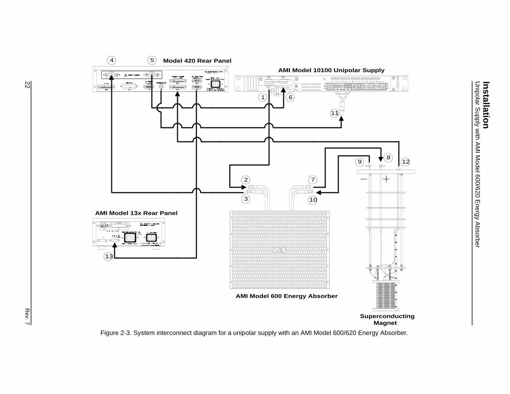
2.5.3 Unipolar Supply with AMI Model 600/620 Energy Absorber
When the Model 420 is used in the dual quadrant mode with legacy AMI hardware, the magnet power supply system consists of the Model 420, a unipolar power supply (typically an AMI Model 10100 or 10200), an energy absorber (an AMI Model 600 for 100 ampere applications or Model 620 for 200 ampere applications) and associated interconnecting cabling. Figure 2-2 depicts the Model 10100 power supply used in conjunction with the Model 600 Energy Absorber and ancillary components.
Connect the cabling in the following manner:
a. Connect the positive (POS) output terminal (1) of the power supply to the positive (+) input cable (2) of the Energy Absorber using 1/4-20 or similar hardware.
Note
The use of locking hardware is recommended for all high current connections.
Warning
Ensure the protective diode remains installed across the output terminals of the power supply with the anode at the ative terminal and the cathode at the itive terminal. Removal of this protective diode may cause serious injury to personnel and damage to the power supply under certain loss of power conditions.
b. Connect the negative (−) input cable (3) of the Energy Absorber to the positive (+) shunt terminal (4) of the Model 420.
Caution
Do not overtighten the nuts on the current shunt terminals of the Model 420 (see the torque specifications on page 7). Overtightening can result in damage to the terminals.
c. Connect the negative (−) shunt terminal (5) of the Model 420 to the negative (NEG) output lug of the power supply (6).
d. Connect the positive (+) output cable (7) of the Energy Absorber to the positive (+) vapor-cooled current lead (8).
e. Connect the negative (−) vapor-cooled current lead (9) to the negative (−) output cable (10) of the Energy Absorber.
Rev. 7 21
22R
ev. 7
Installatio
nU
nipolar Supply w
ith AM
I Model 600/620 E
nergy Absorber
SuperconductingMagnet
11
Unipolar Supply
128
9
er
600/620 Energy Absorber.
! !! "
#
#
$ %
&'("( )'(*
!((!( (((
Model 420 Rear Panel
1
2
3
6
7
13
RS-232
J8S11
ON
!" #$
AMI Model 13x Rear Panel
AMI Model 10100
4 5
10
AMI Model 600 Energy Absorb
Figure 2-3. System interconnect diagram for a unipolar supply with an AMI Model

InstallationUnipolar Supply with AMI Model 600/620 Energy Absorber
f. Connect the coaxial cable from the connector on the back of the Model 420 to the BNC connector attached to the terminal strip on the rear of the power supply (11).
g. Install an instrumentation cable between the magnet support stand top plate connector (12) and the magnet station connector J7A or J7B on the rear of the Model 420.
h. Install an instrumentation cable between the LHe/Temp connectors J8A and/or J8B on the rear of the Model 420 and the Model 13x Liquid Helium Level Instrument and/or temperature instrument (13).
i. Remote communications via IEEE-488 and/or RS-232 (or optional RS-422) can be accomplished by connecting suitable cabling to J11 and/or J12, respectively.
Rev. 7 23

InstallationUnipolar Supply with 610/630 Energy Absorber and Current Reversing Switch
2.5.4 Unipolar Supply with AMI Model 610/630 Energy Absorber and Current Reversing Switch
For a simulated four quadrant power supply system with legacy AMI hardware, the components include the Model 420, a unipolar power supply (typically an AMI Model 10100 or 10200), an energy absorber / reversing switch (an AMI Model 610 for 100 ampere applications or Model 630 for 200 ampere applications) and associated interconnecting cabling. Figure 2-4 depicts the Model 10100 power supply used in conjunction with the Model 610 Energy Absorber / Reversing Switch and ancillary components.
Connect the cabling in the following manner:
a. Connect the positive (POS) output terminal (1) of the power supply to the positive (+) input cable (2) of the Energy Absorber / Reversing Switch using 1/4-20 or similar hardware.
Note
The use of locking hardware is recommended for all high current connections.
Warning
Ensure the protective diode remains installed across the output terminals of the power supply with the anode at the ative terminal and the cathode at the itive terminal. Removal of this protective diode may cause serious injury to personnel and damage to the power supply under certain loss of power conditions.
b. Connect the negative (−) input cable (3) of the Energy Absorber to the positive (+) shunt terminal (4) of the Model 420.
Caution
Do not overtighten the nuts on the current shunt terminals of the Model 420 (see the torque specifications on page 7). Overtightening can result in damage to the terminals.
c. Connect the negative (−) shunt terminal (5) of the Model 420 to the negative (−) output lug of the power supply (6).
d. Connect the positive (+) output cable (7) of the Energy Absorber / Reversing Switch to the positive (+) vapor-cooled current lead (8).
e. Connect the negative (−) vapor-cooled current lead (9) to the negative (−) output cable (10) of the Energy Absorber / Reversing Switch.
24 Rev. 7

Rev. 7
25
Installatio
nU
nipolar Supply w
ith 610/630 Energy A
bsorber and Current R
eversing Sw
itch
!
SuperconductingMagnet
1
S11
ON
AMI
r Supply
138
9
Figure 2-4. Syst r and a current reversing switch.
!! "
#
#
$ %
&'("( )'(*
!((!( (((
Model 420 Rear Panel
1
2
3
6
7
4
RS-232
J8
!" #$
Model 13x Rear Panel
12
AMI Model 10100 Unipola
4 5
10
AMI Model 610 Energy Absorber
11
em interconnect diagram for a unipolar supply with an AMI Model 610/630 energy absorbe

InstallationHigh-Current Four-Quadrant Supply
f. Connect the power and control cables (11) between the control unit and the Energy Absorber / Reversing Switch.
g. Connect the coaxial cable from the connector on the back of the Model 420 to the BNC connector attached to the terminal strip on the rear of the power supply (12).
h. Install an instrumentation cable between the magnet support stand top plate connector (13) and the magnet station connector J7A or J7B.
i. Install an instrumentation cable between the LHe/Temp connectors J8A and/or J8B on the rear of the Model 420 and the Model 13x Liquid Helium Level Instrument and/or temperature instrument (14).
j. Remote communications via IEEE-488 and/or RS-232 (or optional RS-422) can be accomplished by connecting suitable cabling to J11 and/or J12, respectively.
2.5.5 High-Current Four-Quadrant Supply
For a true four quadrant power supply system, the components include Model 420, a four quadrant power supply (typically an AMI Model 4Q05100PS), and associated interconnecting cabling. Figure 2-5 illustrates the interconnects for an AMI Model 4Q05100PS power supply.
Connect the cabling in the following manner:
a. Connect the positive (+) power supply terminal (1) to the positive vapor-cooled current lead (2) using 1/4-20 or similar hardware.
Note
The use of locking hardware is recommended for all high current connections.
Caution
Do not overtighten the nuts on the current shunt terminals of the Model 420 and output terminals of the 4Q05100PS (see the torque specifications on page 7). Overtightening can result in damage to the terminals.
b. Connect the negative vapor-cooled current lead (3) to the positive (+) shunt terminal (4) on the back of the Model 420.
c. Connect the negative (−) shunt terminal (5) on the back of the Model 420 to the negative (−) power supply terminal (6).
26 Rev. 7

Rev. 7
27
Installatio
nH
igh-Current F
our-Quadrant S
upply
uperconductingMagnet
2
8
A
ly Rear Panel
pply.
! !! "
#
#
$ %
&'("( )'(*
!((!( (((
S
Model 420 Rear Panel
3
4 5
6
9
!"
#
RS-232
J8S11
ON
$% &
#
MI Model 13x Rear Panel
7
AMI Model 4Q-05100 Four-Quadrant Supp
1
Figure 2-5. System interconnect diagram for the AMI Model 4Q-05100 power su
InstallationHigh-Resolution Four Quadrant Supply
d. Connect the coaxial cable from the connector on the back of the Model 420 to the connector (7) on the rear of the power supply.
e. Install an instrumentation cable between the magnet support stand top plate connector (8) and the magnet station connector J7A or J7B.
f. Install an instrumentation cable between the LHe/Temp connectors J8A and/or J8B on the rear of the Model 420 and the Model 13x Liquid Helium Level Instrument and/or temperature instrument (9).
g. Remote communications via IEEE-488 and/or RS-232 (or optional RS-422) can be accomplished by connecting suitable cabling to J11 and/or J12, respectively.
2.5.6 Low-Current, High-Resolution Four-Quadrant Supply
AMI offers a low-current (5 A or 10 A maximum) system option to achieve high-resolution control of the magnet current. The system consists of a Model 420, a low-current four-quadrant power supply (typically the Kepco BOP series), and associated interconnecting cabling. Figure 2-6 illustrates the interconnects for a Kepco BOP 20-5M or 20-10M power supply.
Note
Due to continuous discharge voltage limitations present in the Kepco BOP series supplies, the charging/discharging voltage is limited to a maximum of 10 volts by the Model 420 for maximum safety.
Connect the cabling in the following manner:
a. Connect the positive (+) power supply terminal (1) to the positive vapor-cooled current lead (2) using 1/4-20 or similar hardware.
b. Connect the negative vapor-cooled current lead (3) to the positive (+) shunt terminal (4) on the back of the Model 420.
Caution
Do not overtighten the nuts on the current shunt terminals of the Model 420 (see the torque specifications on page 7). Overtightening can result in damage to the terminals.
c. Connect the negative (−) shunt terminal (5) on the back of the Model 420 to the negative (−) power supply terminal (6).
28 Rev. 7

Rev. 7
29
Installatio
nH
igh-Resolution F
our Quadrant S
upply
T OUT GRDGRDNET. COM
SCOM
!
nductinggnet
2
4
6
8
9
RS-2
J8S11
ON
AMI Mod
y
ly.
VOLTAGEPROGRAMMING
INPUT
VOLTAGE
KEPCO
CURRENTMODEVOLTAGE CONTROL
BIPOLAR OPERATIONAL POWER SUPPLY/AMPLIFIER
V +V I +ICURRENT CONTROL
ONOFFON OFF
POWER
ON
OFF
CURRENTPROGRAMMING
INPUT
REMOTE
VOLTAGE LIMITS CURRENT LIMITS
GROUND
SENSE COMMON OUTPUT SENSE
V 0 +V I 0 +I
RED
BLACK
SOU
!! "
#
#
$ %
&'("( )'(*
!((!( (((
SupercoMa
Model 420 Rear Panel
1
3
5
32
!" #$
el 13x Rear Panel
7
Kepco BOP 20-5/10M Suppl10
Figure 2-6. System interconnect diagram for the Kepco BOP series power supp

InstallationHigh-Resolution Four Quadrant Supply
d. Connect the coaxial cable from the connector on the back of the Model 420 to the connector (7) on the front panel of the power supply. Note the cable configuration as shown in the diagram.
e. Install an instrumentation cable between the magnet support stand top plate connector (8) and the magnet station connector J7A or J7B.
f. Install an instrumentation cable between the LHe/Temp connectors J8A and/or J8B on the rear of the Model 420 and the Model 13x Liquid Helium Level Instrument and/or temperature instrument (9).
g. Set the Kepco power supply to voltage control (to the left), and set both manual control switches to the position.
30 Rev. 7

InstallationMagnets w/o Persistent Switch
2.5.7 Third-Party Power Supplies
The Model 420 has been designed to function with a wide variety of third-party power supplies. Please contact an AMI Technical Support Representative for compatibility with specific models. Custom modifications can be made to accommodate supplies that are not compatible with the standard Model 420 configurations.
2.6 Special Configurations
The Model 420 has been designed for optimal operation with a superconducting magnet (i.e. a very low resistance, high inductive load) with a persistent switch. The Model 420 is capable of operating other loads, however, some modification to the instrument settings and/or connections must be considered. Two commonly encountered configurations are 1) superconducting magnets without a persistent switch, and 2) operation on a short-circuit or resistive load.
2.6.1 Superconducting Magnets without a Persistent Switch
For superconducting magnets without a persistent switch, the Model 420 requires the addition of an external stabilizing resistor in parallel with the magnet per Figure 2-7. If the stabilizing resistor is omitted, the system current will oscillate when attempting to charge the magnet.
The general guidelines recommended by AMI for selecting the resistor value and estimating the power handling requirement are as follows:
where R is the required resistance in ohms, L is the magnet inductance in Henries, VL is the voltage limit setting of the Model 420 in volts, and P is the required power rating of the resistor in Watts. For best results, R should be chosen as close to the calculated value as is practical, typically within 25%, with a maximum value not exceeding 20 ohms.
Stabilizing Resistor
Figure 2-7. Illustration of stabilizing resistor in parallel with the magnet.
R 2πL≤
PVL( )2
R-------------=
Rev. 7 31

InstallationOperation on a Short-Circuit
2.6.2 Short-Circuit or Resistive Load
If operating with a short-circuit as a load without the presence of a superconducting magnet, the Model 420 must be manually configured for stability. Normally, when the persistent switch heater is deactivated, the Model 420 essentially sees a short-circuit as the load since the persistent switch shunts all current flow away from any connected magnet. Therefore, one method of operating a short-circuit is to indicate that a persistent switch is present with the persistent switch heater deactivated.
The preferred method is to indicate that a persistent switch is not present (see paragraph 3.2.2.4) and adjust the stability setting (see paragraph 3.2.2.1) to control the load. A stability setting of 100% will always allow control of a short-circuit as the load, regardless of the state of the persistent switch heater.
If the resistance of the load is increased, the stability setting must be decreased to improve the transient response of the system. If the current appears to lag, then decrease the stability setting until the system is responsive. If the current appears to oscillate, increase the stability setting until the oscillations are damped.
Note
If you have purchased a superconducting magnet with the Model 420, AMI will normally provide a recommended stability setting for optimal operation of the magnet system. If you operate the Model 420 with a different load, be sure to restore the stability setting to the recommended value when the superconducting magnet is reconnected.
The stability setting is essentially manual control of the gain of a integrator present in the control logic of the Model 420. Increasing the stability setting decreases the gain of the integrator.
A special case is the energy absorber designs available from AMI. For example, the Model 601 is an infinite-resistance device until 5 VDC is achieved across its terminals. Once the 5 VDC “bias” is present, the Model 601 allows current flow with a nominal 2 mΩ series resistance. Therefore, the Model 420 will require an “integration time” to overcome the 5 VDC bias. Once the bias is achieved, the series resistance is minimal and the Model 601 apears as a short-circuit. It is not possible to decrease the stability setting to remove the integration time, since once the 5 VDC bias is achieved, the load is a short-circuit and the system will become unstable.
Note that when operating with a superconducting magnet in the circuit, the integration gain of the Model 420 will be adequate to quickly “bias” the Model 601 and achieve a proper current ramping profile.
32 Rev. 7

InstallationPower-Up Procedure
2.7 Power-Up and Test Procedure
It is important to verify that the magnet system has been properly connected before the superconducting magnet is energized. This is especially recommended if the system is to be controlled via a computer since this setup will allow software debugging without the potential for damage to the magnet. The following procedures will assist the user in the verifying key system components.
1. Using the appropriate diagram from section 2.5 as a guide, verify all system components are connected as shown. If there is any doubt as to the correct connection of a component, contact an AMI Technical Support Representative. The user is required to properly make a few connections between the various system components which were disconnected to facilitate packing and shipping.
2. Temporarily place a short across the magnet current terminals. This may be most easily accomplished by unfastening the heavy cables from the vapor-cooled current leads and fastening them together. This will allow rudimentary power supply checks without energizing the superconducting magnet.
3. Energize the Model 420 by placing the power switch in the (ON)position.
4. Enter a stability setting of 100% in the Load setup menu. Refer to paragraph 3.2.2.1 on page 44 for more information.
5. Energize the power supply.
Note
Also energize the Model 601/610/630 energy absorber unit if applicable.
6. Verify the various setup menu values for your system (with the exception of the stability setting). If the Model 420 was purchased with an AMI magnet, AMI has preset the setup menu values for proper operation. See paragraph 3.2.5 on page 50 for more discussion of the setup menu values.
7. Set the ramp rate to 1 A/sec. Refer to paragraph 3.3.1.2 on page 54.
8. Set the programmed current to 10 A. Refer to paragraph 3.3.3 on page 55.
9. Initiate ramping to the programmed current by pressing the switch (LED indicator on button should extinguish).
Rev. 7 33

InstallationPower-Up Procedure
10. The system should ramp to 10 amperes in approximately 10 seconds. Verify this is the case.
Note
If an energy absorber unit is connected, the Model 420 may take significantly longer to ramp the current to 10 A. The Model 420 must first develop a supply output voltage to overcome the forward voltage drop of a connected energy absorber. During actual magnet operation, the presence of an energy absorber will not significantly delay the ramping operation since the Model 420 control gain is increased by orders of magnitude when an inductive load is connected.
11. When the programmed current is achieved, the Current/Field Limit LED adjacent to the switch will be illuminated. The display should show “+ 10.00 A −” indicating that the Model 420 is in the holding mode at the programmed current value.
Note
There may be a discrepancy between the current shown on the power supply display and the current displayed on the Model 420. The shunt measurement system incorporated in the Model 420 is normally more accurate than the power supply shunt. The Model 420 is calibrated to 0.1% of the actual current, which is typically five times more accurate than most integrated power supply shunts.
12. Verify that the output current display of the power supply indicates that it is supplying 10 amperes to the load (which is only the cabling in this case).
13. Set the programmed current to the current limit value. Refer to paragraph 3.2.2.3 on page 45 to determine the current limit value. After the new programmed current value is entered, the Model 420 should ramp automatically to the new setting.
14. When the new programmed current value is reached, the power supply current display should also indicate the new value.
15. Press the button to ramp the system to zero current (LED indicator on button should energize).
16. Perform remote control software checkout as required.
17. Turn off the power supply.
34 Rev. 7

InstallationPower-Up Procedure
18. Reset the stability setting and ramp rate of the Model 420 to an appropriate value for the magnet to be operated. Then turn off the Model 420.
19. Remove the short from the power supply leads and connect the leads to the vapor-cooled current leads of the magnet.
After successful completion of this test of the Model 420 and power supply system, the system is ready for operation with a superconducting magnet. Refer to the ramping function example presented on page 57 for a discussion of the various available ramping methods.
Rev. 7 35

InstallationPower-Up Procedure
36 Rev. 7

3 Operation
This section describes each display and operating mode of the Model 420 instrument and the related functions. Every available menu is illustrated and described in detail. An example setup of the instrument is presented in paragraph 3.2.5 on page page 50. An example ramping operation is presented in paragraph 3.3.6 on page 57.
3.1 Default Display Modes
The default display modes are illustrated in the diagram below. There are four default display modes which can be cycled by repeatedly pressing the key when not within the setup menu or a setup submenu. The operating values on the left side of the display are always visible during any mode of operation or menu selections.
!" #"$% &'
( ) *"+ #"$% &'
,-. !", #"$% &'
This portion of the display is always visible.
Default display mode 1: Units of Amps, Supply Voltage Vs.
Default display mode 2: Units of Amps, Magnet Voltage VM.
Ramping mode character
Figure 3-1. Default display modes.
,-. !",+ #"$% &'
Default display mode 3: Units of kG, Supply Voltage Vs.
Default display mode 4: Units of kG, Magnet Voltage VM.
Rev. 7 37

OperationEntering Values
The operating (shunt) current is displayed in Amperes and may alternately be displayed as estimated field in kilogauss (or Tesla) in display mode 3 or 4 if a coil constant has been specified in the setup (see paragraph 3.2.2.2). Vs indicates the commanded output voltage of the power supply in volts. VM indicates the voltage measured across the terminals of the connected superconducting magnet.
The ramping mode character is always visible (except during a quench condition) and is displayed just to the right of the operating current or field display. The ramping mode character may be one of five states as shown in Table 3-1.
If the ramping mode character is blank, then a quench condition exists. See paragraph 3.3 for a detailed discussion of the meaning of the ramping modes.
3.1.1 Entering Numerical Values
A consistent method of entering values is used within menus requiring numerical entries. Once a menu is selected, the user starts an entry by pressing a digit, the decimal key, or the sign () key. The display will begin a new entry and display a cursor as a prompt for the next digit or decimal entry. Once entry is initiated, the display will show an asterisk indicating that entry is in progress. To accept the entered value, press the key. Values are not applied to the operation of the instrument until the key is pressed and the asterisk disappears from the display. An example of an entry in progress is illustrated below:
If the key is pressed once while entry is initiated, the entered digits will be cleared and the cursor will remain for reentry of a new desired value. If the key is depressed twice, the setting will revert to the previous value and the entry is cancelled.
Table 3-1. Description of ramping mode characters.
P Pauseda
a. Displayed in reverse video.
↑ Ramping Up
↓ Ramping Down
– Holding
° Heating Persistent Switch
/
38 Rev. 7

OperationSetup Menu
3.1.2 Menu Option Selection
Some menus may require the user to cycle through and select from a list of predefined options. Such menus will display a cursor which indicates that a list of predefined options are available from which to select. Pressing the key moves the cursor forward within the list. The value to which the cursor points is the specified setting and is effective immediately upon selection (i.e. the key is not required).
3.1.3 Exiting Menus
Menus are exited by pressing the key while no entry is in progress. The display will revert to a default display mode (see paragraph 3.1 above). If the menu is a submenu of the setup mode, then the display reverts to the setup mode selection screen described in paragraph 3.2 below.
3.2 Setup Menu Descriptions
The setup menu is entered by pressing the key. This will initiate the following initial setup menu display:
A cursor 0 displayed to the left of a menu item indicates which setup submenu item will become active when the key is again pressed. The cursor can be moved to the next menu item by pressing the key. The setup menu may be exited by pressing the key once.
Once the key is pressed and a submenu is entered, the user will be able to access several additional parameters illustrated in Figure 3-2 on the following page. Attempts to set a parameter within a submenu to a value outside of the valid range are ignored and, if attempted, the instrument will beep once indicating an error and revert to the previous setting. The key is used to select from a list of options. The dial may also be used to make incremental adjustments to parameters requiring a numerical input (or where indicated with a menu selection). Move to the next parameter within a submenu by pressing the key. Submenus may be exited to the initial setup menu by pressing once.
*+!$ 0**!12+"$
Rev. 7 39

OperationSetup Menu : Supply
3.2.1 Supply Setup Submenu
The Supply setup submenu provides for the specification of the power supply parameters. If you wish to set the limits of operation for a connected magnet, refer to the current limit and the voltage limit configurations.
If using a standard power supply supported by AMI, selecting a power supply within the Select Power Supply menu sets all the remaining parameters in the supply menu according to Table 3-2.
3.2.1.1 Select Power Supply
The select power supply parameter provides a selection menu that contains presets for standard AMI power supplies. Use the key to cycle through the list of selections. The selection becomes effective immediately. If a supply other than Custom... is selected, all remaining items within the Supply submenu are automatically set and cannot be edited. The available selections and associated supply parameters are provided in Table 3-2.
SUBMENUS
PARAMETERS
For
Cus
tom
... s
elec
tion
only
Figure 3-2. Setup menu, submenus, and parameter diagram.
!$#**!1 0+3,
40 Rev. 7

OperationSetup Menu : Supply
Pt
AMI 00
AMI 00
AMI 00
AMI 0
AMI 0
HP 6 00
Kep 00
Kep 00
Xan 00
Cus 00
Note
The operating current must be less than 0.1% of Imax in order to change the supply selection. If a change is attempted above this current, the Model 420 will beep and ignore the keypress. Power supply selection should also preferably be performed with the power supply off for maximum safety.
The power supply settings define the V-I ranges for a specific supply. For example, V-I diagrams are presented in Figure 3-3 for the AMI 12100PS and AMI 4Q05100PS selections. The AMI 12100PS operates as a one-quadrant system without the addition of an energy absorber. With the addition of an energy absorber, the AMI 12100PS system can function as a two-quadrant supply. The AMI 4Q05100PS power supply operates as a four-quadrant power supply without the addition of an energy absorber.
The addition of an energy absorber to the system does not change the capabilities of the power supply (or the values entered for the supply). The addition of an energy absorber does, however, change the system operating ranges per the example of Figure 3-3.
Table 3-2. Available Select Power Supply options.
ower SupplyMin Output Voltage (V)
Max Output Voltage (V)
MinOutput
Current (A)Max Output Current (A)
V-V Mode InpuRange (V)
12100PS +0.000 +12.000 +0.000 +100.000 +0.000 to +10.0
12200PS +0.000 +12.000 +0.000 +200.000 +0.000 to +10.0
4Q05100PS −5.000 +5.000 −100.000 +100.000 −10.000 to +10.0
10100PS +0.000 +10.000 +0.000 +100.000 +0.000 to +5.00
10200PS +0.000 +10.000 +0.000 +200.000 +0.000 to +5.00
260B +0.000 +10.000 +0.000 +100.000 +0.000 to +10.0
co BOP 20-5Ma −10.000 +10.000 −5.000 +5.000 −10.000 to +10.0
co BOP 20-10M −10.000 +10.000 −10.000 +10.000 −10.000 to +10.0
trex XFR 7.5-140 +0.000 +7.500 +0.000 +140.000 +0.000 to +10.0
tom...b −20.000 +20.000 −200.000 +200.000 −10.000 to +10.0
a. The Kepco supplies are limited to only 1/2 of the output voltage range since the supplies are only designed to safely dissipate 1/2 of the rated power output.
b. The values shown for the Custom... option are defaults. The user should enter the appropriate values within the respective submenus. Custom values, once entered, are saved between power-ups.
Rev. 7 41

OperationSetup Menu : Supply
3.2.1.2 Min Output Voltage
The minimum output voltage is specified in volts and reflects the minimum compliance of a connected power supply. The valid range is 0.000 to -20.000 volts. A unipolar power supply has a minimum output voltage of 0.000 volts. This setting can be edited only if a Custom... supply is selected.
3.2.1.3 Max Output Voltage
The maximum output voltage is specified in volts and reflects the maximum compliance of a connected power supply. The valid range is 0.001 to +20.000 volts. This setting can be edited only if a Custom... supply is selected.
3.2.1.4 Min Output Current
The minimum output current is specified in Amperes and reflects the minimum output current capacity of a connected power supply.
20
-20
200-200
20
-20
200-200
VV
I I
AMI 12100PSOPERATING RANGE
AMI 12100PS + MODEL 601ENERGY ABSORBEROPERATING RANGE
AMI 4Q05100PSOPERATING RANGE5V
Figure 3-3. Example power supply operating ranges.
+"&*!
+4&*! ,
+"&*
42 Rev. 7

OperationSetup Menu : Supply
The valid range is 0.000 to as much as -2000.000 Amperes.1 A unipolar power supply has a minimum output current of 0.000 Amperes. This setting can be edited only if a Custom... supply is selected.
3.2.1.5 Max Output Current
The maximum output current is specified in Amperes and reflects the maximum output current capacity of a connected power supply. The valid range is 0.001 to as much as +2000.000 Amperes.1 This setting can be edited only if a Custom... supply is selected.
3.2.1.6 V-V Mode Input Range
The voltage-to-voltage mode input range defines the remote programming voltage range required by the connected power supply. The remote program voltage is the output signal commanded by the Model 420 to drive the connected power supply. This setting can be edited only if a Custom... supply is selected.
This menu item provides five preset selections and does not allow numerical entry of a range. Use the key to cycle through the list of presets. The presets include:
1. The minimum and maximum output currents are bounded by the specific Model 420 configuration purchased. See page 7 for the specifications for each configuration. The entered value cannot exceed the programmable limits.
Table 3-3. Predefined voltage-to-voltage mode input range ranges.
+0.000 to +5.000
+0.000 to +10.000
-5.000 to +5.000
-10.000 to +10.000
+0.000 to -5.000
+4&*
+3*) 0
Rev. 7 43

OperationSetup Menu : Load
3.2.2 Load Setup Submenu
If the Load submenu is selected in setup, then several parameters associated with the superconducting magnet load can be viewed and/or specified by using the key to cycle through the available items.
3.2.2.1 Stability Setting
The stability setting is specified in percent and controls the transient response and stability of the system. The valid range is from 0.0 to 100.0%. The default value is 0.0% unless preset by AMI. The chart below may be used as a guide to set the stability setting for magnets with a persistent switch installed. Magnets with an inductance of greater than 3 Henries that have a persistent switch installed should operate without problems with a stability setting of 0.0%.
3.2.2.2 Coil Constant
The coil constant is a scaling factor which converts the operating current to kilogauss (10 kG = 1 Tesla). It is also often referred to as the field-to-current ratio. The coil constant is specified in kilogauss/
5"!"1"6
Model 420 Stability Setting vs. Magnet Inductance
0
10
20
30
40
50
60
70
80
90
100
0 1 2 3 4 5 6 7
Inductance (H)
Sta
bili
ty S
etti
ng
(%
)
"!-.7 8
44 Rev. 7
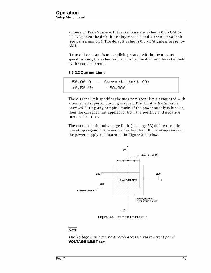
OperationSetup Menu : Load
ampere or Tesla/ampere. If the coil constant value is 0.0 kG/A (or 0.0 T/A), then the default display modes 3 and 4 are not available (see paragraph 3.1). The default value is 0.0 kG/A unless preset by AMI.
If the coil constant is not explicitly stated within the magnet specifications, the value can be obtained by dividing the rated field by the rated current.
3.2.2.3 Current Limit
The current limit specifies the master current limit associated with a connected superconducting magnet. This limit will always be observed during any ramping mode. If the power supply is bipolar, then the current limit applies for both the positive and negative current direction.
The current limit and voltage limit (see page 53) define the safe operating region for the magnet within the full operating range of the power supply as illustrated in Figure 3-4 below.
Note
The Voltage Limit can be directly accessed via the front panel key.
2" "
V
I
10
-10
200-200
EXAMPLE LIMITS
75-75
Current Limit (A)
±2.5
± Voltage Limit (V)
AMI 4Q05100PSOPERATING RANGE
Figure 3-4. Example limits setup.
Rev. 7 45

OperationSetup Menu : Load
3.2.2.4 Persistent Switch Installed
Indicates whether a persistent switch is installed. Use the key to cycle between YES and NO. If YES is selected, the persistent switch current and heating time for the switch must be specified. The default value is YES unless preset by AMI.
3.2.2.5 Persistent Switch Current
The persistent switch current can be set from between 0.1 to 100.0 mA. The default value is 10.0 mA unless preset by AMI.
3.2.2.6 Persistent Switch Heated Time
The persistent switch heated time is the amount of time required for the persistent switch to completely heat and become resistive. The time may be set from 5 to 120 seconds. The default is 15 seconds unless preset by AMI.
During the persistent switch heating period, the Model 420 ramping functions are disabled. The time delay is necessary to ensure that the Model 420 will not switch to a higher gain required for proper magnet operation before the magnet is actually available in the circuit. If magnet operation is not stable after expiration of the heating period, increase the heating period to allow more time for the switch to heat. The default of 15 seconds is adequate for the majority of persistent switches.
3.2.2.7 Enable Quench Detect
The automatic quench detection function of the Model 420 may be enabled or disabled according to the preference of the operator. Use
#"$%3!!9 '& 0:;
#"$%
#"$% <" $
;5!=$%>$9 '& 0:;
46 Rev. 7

OperationSetup Menu : Load
the key to cycle between YES and NO. The default value is YES.
A user input for external quench detection is provided on the rear panel of the instrument. The external input overrides the quench detection function of the Model 420 and cannot be disabled. For further discussion of the quench detection logic and operation, please refer to paragraph 3.5.
3.2.2.8 Energy Absorber Present
Indicates whether an energy absorber, such as the AMI Model 610, is connected to the system. Use the key to cycle between YES and NO. The default value is NO.
It is important for this setting to be correct since the internal gain tables of the Model 420 compensate for the additional load of the energy absorber if present. The increased gain when an energy absorber is present will decrease (but not eliminate) the time required for the system to “forward bias” the energy absorber.
;1559 0'& :;
Rev. 7 47

OperationSetup Menu : Misc
3.2.3 Misc Setup Submenu
The Misc submenu allows specification of the display contrast setting, the ramp rate time units, and the field units.
3.2.3.1 Display Contrast
Adjusts the contrast of the liquid crystal display from 0 to 100%. The default setting is 80%. Enter a value or use the dial to adjust the value.
3.2.3.2 Ramp Rate Time Units
Specifies whether ramp rate is specified and displayed in time units of seconds or minutes. Use the key to cycle between selections. The selected option also applies to the appropriate remote interface commands. The default setting is seconds.
3.2.3.3 Field Units
Specifies whether the field is specified and displayed in units of kilogauss (kG) or Tesla (T). Use the key to cycle between selections. The selected option also applies to the appropriate remote interface commands. The default setting is kilogauss.
>"*!16 ?
*$"@1) *)39 0$ +"
A"!B" 0C"! <!
48 Rev. 7

OperationSetup Menu : Comm
3.2.4 Comm Setup Submenu
The Comm submenu allows specification of parameters associated the IEEE-488 and serial remote interfaces. Consult the Remote Interface Reference section beginning on page 65 for more information regarding the communication interfaces.
3.2.4.1 IEEE-488 Address
Specifies the IEEE-488 primary address of the Model 420. The valid range is from 0 to 30. The Model 420 should be assigned a unique primary address on the IEEE-488 bus. Enter a value or use the dial to adjust the value. The default primary address is 22. The Model 420 does not support secondary addressing.
3.2.4.2 Serial Baud Rate
Specifies the baud rate of the serial interface. Use the key to cycle between values. The default value is 9600 baud.
3.2.4.3 Serial Data Bits/Parity
Specifies the number of data bits and parity for the serial interface. Use the key to cycle between values. The default setting is no 8 data bits/no parity.
3.2.4.4 Serial Stop Bits
Specifies the number of stop bits for the serial interface. Use the key to cycle between values. The default value is 1 stop bit.
3;;;/??D ,,
"!E) , ,/ /? 08
"!>E"7"1 7;F 7& 0?7'
"!*E" 0 ,
Rev. 7 49

OperationExample Setup
3.2.4.5 Serial Handshaking
Specifies whether the serial interface uses no handshaking or software handshaking (commonly referred to as XON/XOFF). Hardware handshaking is not supported. Use the key to cycle between values. The default setting is no handshaking.
3.2.5 Example Setup
As a precursor to operating a superconducting magnet with the Model 420 programmer and power supply, all of the setup items should be reviewed and set if necessary with appropriate values for the connected superconducting magnet.
Figure 3-5 shows an exam-ple magnet specifications sheet. Several parameters needed to operate the mag-net are specified. These values should be entered into the appropriate setup menu of the Model 420. For the purposes of this example, the AMI Model 12100PS power supply without an energy absorber will be assumed, since rated current for the example magnet is 76.23 A.
The current limit accessible in the Load setup submenu should be set to the rated current to prevent accidental operation of the magnet
above rated current/field. The magnet specification sheet also indicates whether a persistent switch is installed and provides the recommended heating current. The persistent switch information is entered in the load setup submenu.
"! %-" 0'GH&'7H&AA
MAGNET SPECIFICATIONS
AMI JOB #10501 MAGNET #10228
Type: Solenoid
MODEL: A9020-3
TEST DATE: April 22, 2002
Rated Central Field @ 4.2K --------------- 90 KG
Rated Current ---------------------------- 76.23 Amps
Maximum Test Field @ 4.2K * -------------- 92 KG
Measured Field to Current Ratio ---------- 1180.6 Gauss/Amp
Homogeneity over 1 cm DSV ---------------- +/- 0.1%
Measured Inductance ---------------------- 9.8 Henries
Charging Voltage (Used in test) ---------- 2.0 Volts
Axial Clear Bore ------------------------- 2.0 inches
Overall Length (flange to flange) -------- 8.0 inches
Maximum Outside Diameter ----------------- 4.6 inches
Weight ----------------------------------- 28 lbs.
Recommended Persistent Switch Heater Current ----- 46 mA
Persistent Switch Heater Nominal Resistance** ---- 69 Ohms
Magnet Resistance in Parallel with Switch** ------ 21 Ohms
Mounting: 3 Holes tapped for 10-32 on top and bottom flanges, equally spaced on a 3.00 inch B.C.D.
* Magnet not warranted for operation above 90 KG field.
** All resistance measurements made at room temperature.
Figure 3-5. Example magnet specification sheet.
50 Rev. 7

OperationExample Setup
If your magnet, programmer, and power supply were purchased as a system from AMI, the setup menus are preset by AMI to match the magnet purchased.
Table 3-4 provides a summary of the Model 420 setup parameters for this example.
Table 3-4. Example Setup Configuration
Select Power Supply AMI 12100PS
Stability Setting (%) 0.0
Coil Constanta (kG/A)
a. Also referred to as the Field-to-Current Ratio. Obtained by dividing the rated field by the rated current if not explicitly stated.
1.1806
Current Limit (A) 76.300
PSwitch Installed? YES
PSwitch Current (mA) 46.0
PSwitch Heated Time (sec) 15
Enable Quench Detect? YES
Energy Absorber Present? NO
Programmed Current (A) 76.2300
Voltage Limit (V) 4.000b
b. Value is the 2 V charge rate plus allowances for power lead drop at the rated current. If a Model 601 energy absorber is present, add an additional 5 V to the value.
Ramp Rate (A/sec) 0.2041c
c. Value is obtained by dividing the charge rate (V) by the inductance (H).
Rev. 7 51

OperationRamping Functions
3.3 Ramping Functions
The ramping functions are used to control charging of the superconducting load. The Model 420 allows a piecewise-linear charging profile to be defined and executed. The basic charging equation for a superconducting magnet is:
where V is the charging voltage (V), L is the magnet inductance (Henries), and di/dt is the ramp rate (A/s). The relationship may also be defined in terms of a ramp rate in kG/s by the relationship:
where C is the coil constant (or field-to-current ratio) in kG/A, and dF/dt is the ramp rate expressed in kG/s.
A desired ramp rate should be selected by the operator and entered into the Model 420. A voltage limit should also be specified that is greater than or equal to the voltage calculated from the equations above (remember to account for power lead resistance).
Once the ramp rate and voltage limit are specified, the Model 420 provides two modes of ramping operation: manual and programmed. The manual mode of operation will ramp to the current limit via manual direction control by the user. The programmed mode of operation ramps to a programmed current or field setting automatically. The programmed mode can be thought of as a “next point” operation, whereby the Model 420 determines the appropriate ramp direction based on the present magnet current and the programmed value.
Note
You may enter up to 10 digits beyond the decimal point within the ramping control menus. These extra digits are maintained in the internal memory of the Model 420 even though the full precision is not displayed after entry.
3.3.1 Ramping States and Controls
The ramping state may be one of several values as described in Table 3-5.
If the key is illuminated, the PAUSED mode is active. To continue ramping in programmed mode, press the key to deactivate the PAUSED mode.
V Lidtd
----=
VLC----
Fdtd
------=
52 Rev. 7

OperationRamping Functions : Voltage Limit and Ramp Rate
If manual mode operation is desired, press either the or keys for manual control ramping up or ramping down, respectively.
A voltage limit and ramp rate may be specified from quickly accessible menus from the front panel keypad. The settings for the voltage limit and the ramp rate are applicable to both the manual and programmed modes of operation.
3.3.1.1 Voltage Limit
The voltage limit is accessed by pressing the key and may be set less than or equal to the maximum output voltage of the power supply (see Table 3-2 on page 41). The voltage limit does not require a sign since it functions as both the negative and positive limit. The voltage limit constrains the commanded output voltage of a connected power supply to a value less than or equal to the limit.
Table 3-5. Ramping states and descriptions.
Mode Description
Ramping Automatic ramping to the programmed current or
fielda is in progress.
a. The programmed current/field setting is discussed in paragraph 3.3.3.1.
Holding The programmed current has been achieved and is being maintained.
Paused Ramping is suspended at the current achieved at the time the PAUSED mode was entered.
Manual Ramping is being controlled by the functions available on the front panel.
Zeroing Current
The mode is active, and the instrument is ramping current to 0 A.
At Zero Current
The mode is still active, and the current is less than 0.1% of Imax.
Heating Switch
The persistent switch heater has been activated. Ramping is disabled during the persistent switch heating period.
!2" " I
Rev. 7 53

OperationRamping Functions : Manual and Programmed Modes
The voltage limit may be entered directly via the keypad or adjusted using the dial. Attempts to set the voltage limit above the maximum output of the power supply are ignored and, if attempted, the instrument will beep once indicating an error and revert to the previous setting.
3.3.1.2 Ramp Rate
The ramp rate is accessed by pressing the key. The ramp rate may be set within the range specified in the specifications table for a specific Model 420 configuration (see page 7). Attempts to set the ramp rate outside of the valid range are ignored and, if attempted, the instrument will beep once indicating an error and revert to the previous setting. The ramp rate may be entered directly via the keypad or adjusted using the dial.
If the selected default display contains units of field, then the ramp rate setting is displayed and set in units of kilogauss/sec (or Tesla/sec) as show below. The allowable range is defined by the setting of the coil constant and the allowable range of the ramp rate in terms of current as specified on page 7.
The Model 420 will ramp at the specified rate if the available compliance of the power supply is sufficient and the voltage limit is not exceeded. The Model 420 automatically decreases the ramp rate internally during operation if either the available compliance of the power supply is insufficient, or the voltage limit is active.
3.3.2 Ramping in Manual Mode
The two keys labeled as and control the ramping function in manual mode. If the is pressed and becomes illuminated, the Model 420 will ramp up at the ramp rate setting. The ramping may be paused by pressing the key again (or by pressing ) to deactivate the manual up mode. Once deactivated, the key will become illuminated indicating that the PAUSED mode has been entered.
) *)7$
/-. ) *)-.7$ /
54 Rev. 7

OperationRamping Functions : Manual and Programmed Modes
If the key is pressed, the Model 420 will ramp down at the ramp rate setting. The ramping may be paused by pressing the key again (or by pressing ) to deactivate the manual down mode.
The manual up or down modes will continue ramping until paused or the current limit for the magnet specified in setup (see paragraph 3.2.2.3) is achieved.
3.3.3 Ramping in Programmed Mode
Ramping in programmed mode differs from the manual mode in that the Model 420 automatically performs ramping in the appropriate direction to achieve the value of the programmed current setting. Programmed mode is active when the or keys for the are not illuminated, and the key is not illuminated.
3.3.3.1 Programmed Current/Field
The programmed current is accessed by pressing the key and may be set less than or equal to the current limit for the magnet specified in setup (see paragraph 3.2.2.3). The programmed current requires a sign since it locates a single setpoint within the entire operating current range of the system.
If the selected default display mode contains field units, the display will allow entry of a programmed field value in units of kilogauss (or Tesla) as shown below. The programmed field must also be set within the current limit for the magnet.
The programmed current/field setting may be entered directly via the keypad, or adjusted using the dial if the PAUSED mode is not active (see paragraph 3.3.5 if PAUSED is active). Attempts to set the programmed current/field above the current limit for the magnet are ignored and, if attempted, the instrument will beep once indicating an error and revert to the previous value.
/-. A"!-. /
Rev. 7 55

OperationRamping Functions : Manual and Programmed Modes
3.3.4 Ramp to Zero Mode
If a quench condition does not exist, the key activates an immediate ramp to zero current. When the zero mode is activated, the key is illuminated and the Model 420 automatically ramps the current to 0 A at the set ramp rate while observing the voltage limit. The zero mode may be interrupted at any time by pressing the key to deactivate the function or pressing the , , or keys. If the key is deactivated, the Model 420 will automatically enter the PAUSED mode and maintain the operating current present at the point it was paused.
3.3.5 Dial Adjustment of Current/Field in PAUSED Mode
If the programmed current/field menu is active and the instrument is in PAUSED mode (indicated if the button is illuminated), the dial can be used to directly manipulate the operating (shunt) current.
Note
The encoder dial is velocity-sensitive, meaning that the faster the dial is turned, the more coarse the adjustment. Slow manipulation of the dial will yield very fine resolution even beyond that displayed by the instrument.
When the dial is manipulated the Model 420 will follow at a compliance of less than or equal to the voltage limit. The ramp rate setting is not observed in this operational mode, however, the voltage limit is strictly observed and is never exceeded.
Adjustment of the current in this mode is also prevented from exceeding the current limit specified in the Load setup menu (see paragraph 3.2.2.3). The adjustment may, however, exceed the programmed current/field setting. The resolution of the adjustment is 15 digits, which is greater than the resolution of the display.
Caution
Entering a voltage limit via the key is strongly advised if you wish to adjust the current using this method. Otherwise, large changes using the dial can result in voltages across the terminals of the magnet capable of causing a quench in some magnets.
56 Rev. 7

OperationRamping Functions Example
3.3.6 Ramping Functions Example
As an example of ramping to two programmed current settings, refer to Figure 3-6 below. Each step is labeled as 1 through 8 in Figure 3-6. The Model 420, for the purposes of the example, is assumed to be in the PAUSED mode at 0 A at the beginning of the ramp.
Point 1. The operating current is 0 A and the Model 420 is in the PAUSED mode. The operator sets the programmed current to -30.000 A. The key is pressed so that the PAUSED mode is no longer active and the Model 420 begins ramping current.
Point 2. The programmed current setting of -30.000 A is achieved and the Model 420 switches to HOLDING mode.
Point 3. The operator increases the ramp rate setting. The operator also keys in a new value of +40.000 A for the programmed current setting. As soon as the new programmed current is entered, the Model 420 automatically begins ramping at the specified ramp rate.
Point 4. The operator presses the key at an operating current of 25.15 A and the PAUSED mode is activated. The Model 420 maintains the operating current in the PAUSED mode.
Point 5. The operator presses the key once again to resume ramping.
Point 6. The programmed current setting of +40.000 A is achieved and the Model 420 switches to HOLDING mode. At this point the operator deactivates the persistent switch heater which removes the magnet from the circuit.
1
4
6 7
8
2 3
PROGRAMMEDCURRENT 1
50 A
-50 A
PROGRAMMEDCURRENT 2
Time
5
Figure 3-6. Example of ramping to two different programmed current settings.
Rev. 7 57

OperationRamping Functions Example
Point 7. The operator increases the ramp rate and presses the key to begin ramping to zero current. The Model 420 automatically ramps the current to 0 A.
Point 8. The Model 420 holds the operating current of 0 A when achieved until the key is deactivated.
58 Rev. 7

OperationPersistent Switch Heater
3.4 Persistent Switch Heater Control
The Model 420 includes an integral persistent switch heater that provides the capability of controlling the persistent mode of the magnet either locally from the front panel of the instrument using the switch heater control, or remotely through a communications interface.
If the switch heater control is illuminated, the Model 420 is supplying current to the appropriate pins (9 & 10) of the Magnet Station Connectors in order to drive the persistent switch into a normal state. The switch heater control illuminates if activated via the front panel, or if a remote command activates the heater.
The Model 420 will beep once (indicating an error) if the user attempts to activate the switch heater control without first indicating a persistent switch is installed in the load setup submenu and specifying the switch heating current and heating time (see page 46).
The nominal switch heating current is provided with the magnet specification sheet and may be entered in the Model 420 by accessing the load setup submenu (see paragraph 3.2.2.5). In addition to the heating current, the operator must also specify a heating time. The heating time allows the Model 420 to delay compensating the internal control logic until the magnet is guaranteed to be in the circuit. The heating time can be set from a minimum of 5 seconds to a maximum of 120 seconds within the load setup submenu (see paragraph 3.2.2.6). The default heating period of 15 seconds is adequate for the majority of persistent switches. If the magnet appears unstable just after the switch heating period expires, increase the switch heating time to allow for complete heating.
Note
If the persistent switch function is enabled, press the 1 key in the default display to show the switch heater voltage for 3 seconds. The feature is provided to allow for a quick sanity check for the heater operation. This voltage, divided by the switch heater current, should be approximately equal to the switch heater resistance during proper operation. If this is not the case, check all hardware connections.
Note
During the period the switch is being heated, the Model 420 will not allow ramping functions to be executed and will beep once if the operator attempts to initiate a ramping operation.
Rev. 7 59

OperationPersistent Switch Heater
3.4.1 Procedure for Entering Persistent Mode
In order to enter the persistent mode of magnet operation, the operator should perform the following steps:
1. Use either the programmed or manual ramping modes of the Model 420 to achieve the desired current or field.
2. The Model 420 should be in either the HOLDING or PAUSED mode at the desired current or field.
3. Record the desired current or field setting.
4. Deactivate the switch heater control (the LED indicator should extinguish).
5. Wait until the switch heater is completely cooled before changing any parameters. Most persistent switches cool to superconducting state in a few seconds if completely submerged in liquid helium.
6. Once the switch has cooled, the Model 420 may be used to ramp the current to zero at an increased ramp rate (since the magnet is no longer in the circuit). Using the ZERO mode is recommended since it allows the programmed current/field to remain unchanged for future sessions.
7. Once at zero current, de-energize the power supply first, then power-off the Model 420 instrument.
3.4.2 Procedure for Exiting Persistent Mode
To exit the persistent mode of magnet operation, the operator should perform the following steps:
1. If the Model 420 has been powered-off, then first energize the Model 420. After the Model 420 has been energized, energize the power supply.
2. Using the value of current or field recorded when the magnet last entered the persistent mode, use either the programmed or manual ramping modes of the Model 420 to achieve the last recorded value of current or field.
3. The Model 420 should be either in the HOLDING or PAUSED mode at the last recorded value of current or field.
4. Activate the switch heater control (the LED indicator should illuminate). Note that the Model 420 will enter the HEATING
60 Rev. 7

OperationQuench Detection
SWITCH mode and disallow any ramping during the switch heating period.
5. Once the switch heating period expires, the Model 420 will enter the PAUSED mode and will maintain the operating current or field.
Note
If the actual current in the magnet and the operating current of the Model 420 exhibit a mismatch at the time the switch heater is activated, the Model 420 will track the actual current of the magnet during the switch heating period. At the expiration of the switch heating period, the Model 420 will attempt to maintain the last measured current value.
3.4.3 Optional Switching of External Power Supply
The Model 420 offers the option of using an external power supply for the persistent switch heating current if the requirements for the switch heater exceed the capabilities of the integrated switch heating output of the Model 420. The external power supply, if properly connected, will be switched via an internal relay that opens and closes with the switch heater control functions of the Model 420.
To use an external power supply for the switch heater current, connect an external power supply to J4 pins 4 and 5 (any polarity). Then connect pins 18 and 19 of J7A or J7B to the switch heater terminals of the superconducting magnet. Ensure that the external power requirements are within the limits shown in the specifications table on page 7.
3.5 Quench Detection
The Model 420 continuously monitors the superconducting magnet load and can automatically detect a quench condition. If a quench is detected, the quench detection LED will become illuminated and the display will appear as shown below. When a quench is detected, the Model 420 automatically sets the power supply output voltage to zero, provides a quench output signal to the rear panel connector J4 (see page 109 of the Appendix for the connector pinout), and will not respond to further input until the button is pressed to clear the quench detect condition, or until the quench condition is cleared by a remote command.
//D =$%>$J? #"$% &'
Rev. 7 61

OperationQuench Detection
If the key is pressed to clear the quench condition or a remote clear command is issued, the Model 420 will automatically enter the PAUSED mode and will attempt to maintain the operating current present at the point the quench condition was cleared.
In addition, the rear panel connector, J4, provides pins for external quench input (see page 109 of the Appendix for the connector pinout). If the quench input is asserted, then the Model 420 interprets this input as indication of a quench condition and the Model 420 automatically sets the power supply output voltage to zero and will not respond to further input until the button is pressed to clear the quench detect condition, or until the quench condition is cleared by a remote command. The rear panel input cannot be disabled, however, it may be left unconnected without the possibility of a generating a false quench condition.
Note
If the external quench detection circuit continues to assert the quench detection input of the Model 420, the key will be unable to clear the quench condition.
3.5.1 Disabling Automatic Quench Detection
The automatic quench detection feature may be disabled in the load setup submenu (see paragraph 3.2.2.7). However, the rear panel quench detect input (connector J4) remains active.
If the automatic quench detection feature is disabled, the Model 420 attempts to limit the error, between the commanded current and the present operating current, to a value that will not result in excessive voltages being introduced across the magnet terminals. Under most operating conditions this will not damage any internal protection circuits of the magnet. If an actual quench condition occurs, the Model 420 will follow the magnet current to zero unless the operator intervenes. If the rear panel quench detect input (connector J4) is asserted, the Model 420 will force the power supply output to zero volts regardless of whether the automatic quench detection is enabled or disabled.
In the event that the persistent switch becomes normal without operator or remote activation of the switch heater control, the Model 420 will match the magnet current and attempt to stabilize the load if the automatic quench detection feature is disabled. If the automatic quench detection feature is enabled, then this event will generally trigger the quench detection logic if a difference exists between the magnet current and the operating current of the Model 420.
62 Rev. 7

OperationSummary of Operational Limits
3.6 Summary of Operational Limits and Default Settings
Table 3-6 provides a summary of the operational limits and the default setting for all Model 420 parameters. If the operator attempts to enter a value outside of the limits, the Model 420 will beep once and revert to the previous setting.
References to the specifications on page 7 indicate that the absolute limit is determined by the specific configuration of the Model 420 purchased.
Table 3-6. Summary of limits and defaults for the Model 420.
Model 420 Setting (Units) Absolute Limits Default Settinga
a. Unless preset by factory.
Min Output Voltage (V) 0.000 to −20.000 0.000
Max Output Voltage (V) 0.001 to +20.000 12.000
Min Output Current (A) (see page 7) 0.000
Max Output Current (A) (see page 7) 100.000
V-V Mode Input Range (V) −10.000 to +10.000 0.000 to +10.000
Stability Setting (%) 0.0 to 100.0 0.0
Coil Constant (kG/A) 0.001 to 999.99999 0.0
PSwitch Current (mA) 0.1 to 100.0 10.0
PSwitch Heated Time (sec) 5 to 120 15
Current Limit (A) ≥ Min Output Current and ≤ Max Output Current
80.000
Display Contrast (%) 0 to 100 80
Voltage Limit (V) ≥ 0.001 and ≤ Max Output Voltage
2.000
Ramp Rate (A/sec) (see page 7) 0.100
Programmed Current (A) ≤ Current Limit 5.000
Rev. 7 63

OperationSummary of Operational Limits
64 Rev. 7

4 Remote Interface Reference
The Model 420 provides both RS-232 and IEEE-488 interfaces as standard features. Upon request, the RS-232 port can be reconfigured for RS-422 operation. The serial and IEEE-488 interfaces may operated simultaneously. Separate output buffers are also provided for the serial and IEEE-488 return data. However, for optimal performance and simplicity of programming, AMI normally recommends limiting operation to one interface. An exception to this recommendation would be using the serial port as a debugging aid during programming of the IEEE-488 port (or vice-versa), which can prove to be a useful resource.
4.1 SCPI Command Summary
The following manual conventions are used for SCPI (Standard Commands for Programmable Instruments) syntax for the remote interface commands:
Braces enclose valid parameter choices.
A vertical bar | separates multiple choices for each parameter.
Triangle brackets < > indicate that you must supply a value.
Parentheses ( ) within < > indicate alternative units are available.
For example, the command PSwitch 0|1 indicates that the command PSwitch has two parameter options: 0 or 1. Refer to the detailed description of each command for information regarding specific parameter choices and their meanings. Capitalized portions of the commands indicate acceptable abbreviations. Default settings are shown in bold.
(see page 79 for more information)
*IDN?*RST*TST?<Ctrl-C>
SYSTem:LOCalSYSTem:REMoteSYSTem:TIME?SYSTem:TIME:RESetSYSTem:ERRor?
System-Related Commands
Rev. 7 65

Remote Interface ReferenceSCPI Command Summary
(see page 80 for more information)
*STB?*SRE <enable_value>*SRE?
*CLS
*ESR?*ESE <enable_value>*ESE?
*PSC 0|1*PSC?*OPC*OPC?
(see page 82 for more information)
CONFigure:STABility <percent>CONFigure:COILconst <value (kG/A, T/A)>CONFigure:CURRent:LIMit <current>
CONFigure:PSwitch 0|1CONFigure:PSwitch:CURRent <current>CONFigure:PSwitch:TIME <time>
CONFigure:QUench:DETect 0|1CONFigure:ABsorber 0|1
CONFigure:RAMP:RATE:UNITS 0|1CONFigure:FIELD:UNITS 0|1
Status System Commands
SETUP Configuration Commands
66 Rev. 7

Remote Interface ReferenceSCPI Command Summary
(see page 82 for more information)
SUPPly:VOLTage:MINimum?SUPPly:VOLTage:MAXimum?
SUPPly:CURRent:MINimum?SUPPly:CURRent:MAXimum?
SUPPly:TYPE?SUPPly:MODE?
STABility?COILconst?CURRent:LIMit?
PSwitch:CURRent?PSwitch:TIME?
QUench:DETect?ABsorber?
RAMP:RATE:UNITS?FIELD:UNITS?
SETUP Configuration Queries
Rev. 7 67

Remote Interface ReferenceSCPI Command Summary
(see page page 85 for more information)
CONFigure:VOLTage:LIMit <voltage>
CONFigure:CURRent:PROGram <current>CONFigure:FIELD:PROGram <field (kG, T)>
CONFigure:RAMP:RATE:CURRent <rate (A/s, A/min)>CONFigure:RAMP:RATE:FIELD <rate (kG/s, kG/min, T/s, T/min)>
CONFigure:RAMP:CURRent <current>,<rate (A/s, A/min)>CONFigure:RAMP:FIELD <field (kG, T)>,<rate (kG/s, kG/min, T/s, T/min)>
VOLTage:LIMit?
CURRent:PROGram?FIELD:PROGram?
RAMP:RATE:CURRent?RAMP:RATE:FIELD?
RAMP:CURRent?RAMP:FIELD?
VOLTage:MAGnet?VOLTage:SUPPly?CURRent:MAGnet?FIELD:MAGnet?
(see page 87 for more information)
RAMPPAUSEUPDOWNZERO
STATE?
Ramp Configuration Commands and Queries
Ramping State Commands and Queries
68 Rev. 7

Remote Interface ReferenceSCPI Introduction
(see page 88 for more information)
PSwitch 0|1PSwitch?VOLTage:PSwitch?
(see page 89 for more information)
QUench 0|1QUench?
(see page 90 for more information)
*ETE <enable_value>*ETE?*TRG
4.2 Programming Overview
The Model 420 conforms to the SCPI (Standard Commands for Programmable Instruments) IEEE standard. The SCPI standard is an ASCII-based specification designed to provide a consistent command structure for instruments from various manufacturers.
The Model 420 also implements a status system for monitoring the state of the Model 420 through the Standard Event and Status Byte registers.
4.2.1 SCPI Language Introduction
SCPI commands conform to a tree structure where commands are grouped according to common keywords. For example, commands which set a Model 420 setup or operating parameter begin with the keyword CONFigure. The keywords are shown in upper case and lower case to indicate acceptable abbreviations. For the example keyword CONFigure, the user may send either the abbreviated form of CONF, or the entire keyword CONFIGURE. Any other form of the keyword is illegal and will generate an error.
Switch Heater Commands and Queries
Quench State Control and Queries
Trigger Control and Queries
Rev. 7 69
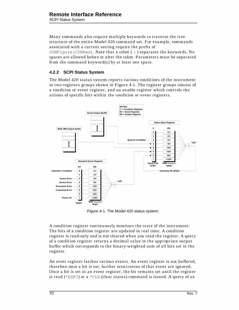
Remote Interface ReferenceSCPI Status System
Many commands also require multiple keywords to traverse the tree structure of the entire Model 420 command set. For example, commands associated with a current setting require the prefix of CONFigure:CURRent. Note that a colon ( : ) separates the keywords. No spaces are allowed before or after the colon. Parameters must be separated from the command keyword(s) by at least one space.
4.2.2 SCPI Status System
The Model 420 status system reports various conditions of the instrument in two registers groups shown in Figure 4-1. The register groups consist of a condition or event register, and an enable register which controls the actions of specific bits within the condition or event registers.
A condition register continuously monitors the state of the instrument. The bits of a condition register are updated in real time. A condition register is read-only and is not cleared when you read the register. A query of a condition register returns a decimal value in the appropriate output buffer which corresponds to the binary-weighted sum of all bits set in the register.
An event register latches various events. An event register is not buffered, therefore once a bit is set, further occurrences of that event are ignored. Once a bit is set in an event register, the bit remains set until the register is read (*ESR?) or a *CLS (clear status) command is issued. A query of an
00
11
22
33
44
55
66
77
<1><1>
<2><2>
<4><4>
<8><8>
<16><16>
<32><32>
N/AN/A
<128><128>
*SRE <value>*SRE?
Serial Poll*STB?
C EN
Summary Bit (RQS)
"OR"
Status Byte Register
00
11
22
33
44
55
66
77
<1><1>
<2><2>
<4><4>
<8><8>
<16><16>
<32><32>
<64><64>
<128><128>
*ESE <value>*ESE?*ESR?
EV EN
"OR"
Standard Event Register
Operation Complete
Query Error
Device Error
Execution Error
Command Error
Power On
Quench Condition
IEEE-488 Output Buffer
Serial Output Buffer
NOTES:C = Condition RegisterEV = Event RegisterEN = Enable Register
Figure 4-1. The Model 420 status system.
70 Rev. 7

Remote Interface ReferenceSCPI Status System
event register returns a decimal value in the appropriate output buffer which corresponds to the binary-weighted sum of all bits set in the register.
An enable register (or bitmask) defines which bits in an event register are reported to the Status Byte register group. An enable register can be both written and queried. The *CLS (clear status) command does not clear an enable register. To enable or disable bits in an enable register, write a decimal value which corresponds to the binary-weighted sum of the bits you wish reported to the Status Byte register.
4.2.2.1 Status Byte Register
The Status Byte register group reports conditions from the Standard Event register or output buffers. Data in the output buffer is immediately reported in the “IEEE-488 Message Available” bit (bit 4) or the “Serial Message Available” bit (bit 3). Clearing a bit in the Standard Event register will update the corresponding bit in the Status Byte register, according to the Standard Event enable register. Reading the pending messages in the output buffers will clear the appropriate “Message Available” bit. The bit definitions for the Status Byte register are defined in Table 4-1.
The Status Byte register provides the capability of generating a user-defined IEEE-488 service request (SRQ) by enabling the desired bits using the *SRE <value> command. If a Status Byte register bit is enabled, then when that bit is set, an SRQ is generated on the IEEE-488 bus. For
Table 4-1. Bit definitions for the Status Byte register.
Bit NumberDecimal
Value Definition
0 Not Used 1 Always “0”.
1 Not Used 2 Always “0”.
2 Quench Condition 4 The Model 420 has detected a quench.
3 Serial Message Available
8 The serial output buffer contains unread data.
4 IEEE-488 Message Available
16 The IEEE-488 output buffer contains unread data.
5 Standard Event 32 One or more enabled bits are set in the Standard Event register.
6 Status Byte Summary
64 One or more enabled bits are set in the Status Byte register.
7 Not Used 128 Always “0”.
Rev. 7 71

Remote Interface ReferenceSCPI Status System
example, if the command *SRE 4 is sent to the Model 420, then if a quench detect subsequently occurs, the Model 420 will immediately generate an SRQ on the IEEE-488 bus.
Bit 2 of the Status Byte register, indicating a quench condition, remains set until the quench condition is cleared via the front panel or by remote command. However, an SRQ is only asserted when the quench is first detected. Bits 3 and 4, indicating available data in an output buffer, are similar in that the SRQ is only asserted when data is first available in an output buffer. Bits 3 and 4 remain set until all data has been read from the respective output buffer.
The Status Byte condition register is cleared when:
A *CLS command is executed.
The Standard Event register is read (only bit 5 of the Status Byte register is cleared).
The indicated condition no longer exists.
The Status Byte enable register is cleared when:
The *SRE 0 command is executed.
The power is turned off and then back on, and the instrument was configured for *PSC 1 (power-on status clear). The enable register setting is persistent if the Model 420 is configured for *PSC 0 (no status clear on power-on).
4.2.2.2 Serial Polling and the Service Request (SRQ)
In order to use the SRQ feature of the Model 420, you must configure your host computer and IEEE-488 interface card to respond to the IEEE-488 service request. If the Status Byte enable register enables any bits of the Status Byte register, then the enabled bit(s) will generate an SRQ when they transition from “0” to “1”. The host computer can then poll the instruments on the IEEE-488 bus to determine which is asserting the service request line (the instrument which returns a response to a Serial Poll with bit 6 set).
Note
If the Model 420 receives a Serial Poll, bit 6 of the Status Byte register is cleared and the service request line (SRQ) is cleared.
If more than one bit is enabled in the Status Byte enable register, then the user must query the Status Byte register by issuing either a Serial Poll message, or the *STB? command. A Serial Poll is executed immediately by the Model 420 and may not reflect the effects of the most recently executed
72 Rev. 7

Remote Interface ReferenceSCPI Status System
command. Use the *OPC? command for positive indication that all prior commands have been executed.
4.2.2.3 Reading the Status Byte using *STB?
The *STB? returns the contents of the Status Byte register, but it is processed in the command queue like any other command. The *STB? command returns the same result as a Serial Poll, however bit 6 of the Status Byte register is not cleared. Issuing an *STB? query does not clear an SRQ condition.
4.2.2.4 Using the Message Available Bit(s)
The “Message Available” bits (bits 3 or 4) of the Status Byte register can be used to determine when data is available to read into your host computer. The instrument clears the “Message Available” bits only after all data has been read from the output buffer(s).
The “Message Available” bits of the Status Byte register are useful for determining if queries have executed, however, they are not useful alone for determining if commands have completed execution, since commands do not provide return data.
4.2.3 Standard Event Register
The Standard Event register group reports a power-on condition, various error conditions, and indicates when an operation has completed. Any or all of the Standard Events can be reported to the Status Byte register by enabling the corresponding bit(s) in the Standard Event enable register (see Figure 4-1). To set the Standard Event enable register, write a binary-weighted decimal value using the *ESE <value> command.
The bit definitions for the Standard Event register are provided in Table 4-2. To query the instrument for the details of a reported error in the Standard Event register, use the SYSTem:ERRor? query. See paragraph 4.6 for a complete discussion of the error buffer and messages.
The Standard Event register is cleared when:
The *CLS (clear status) command is executed.
The Standard Event register is queried using the *ESR? command.
The Standard Event enable register is cleared when:
The *ESE 0 command is executed.
The power is turned off and then back on, and the instrument was configured for *PSC 1 (power-on status clear). The enable register setting is persistent if the Model 420 is configured for *PSC 0 (no status clear on power-on).
Rev. 7 73

Remote Interface ReferenceCommand Handshaking
4.2.4 Command Handshaking
The Model 420 provides an internal command queue that can store up to 4 commands or queries. However, it is possible that the host computer can overwhelm the command queue by sending commands faster than the Model 420 can execute. If the Model 420 cannot process a command due to a full command queue, the command is ignored and the -303,"Input overflow" error is reported.
Handshaking is generally not a concern unless more than 4 commands are sent sequentially. If a query is sent, the user will normally wait for return data for the queries before proceeding to send the next query or command. In the case of sending numerous commands in sequence, there are two methods available to help prevent command queue overflows which are discussed below.
4.2.4.1 Using the *OPC Command
The *OPC command is executed within the normal command queue. Upon completed execution of the *OPC command, the “Operation Complete” bit (bit 0) of the Standard Event register will be set.
Table 4-2. Bit definitions for the Standard Event register.
Bit NumberDecimal
Value Definition
0 Operation Complete 1 All commands prior to and including *OPC have been executed.
1 Not Used 2 Always “0”.
2 Query Error 4 A query error occurred. See the error messages in the -200 range.
3 Device Error 8 A device error occurred. See the error messages in the -400 range.
4 Execution Error 16 An execution error occurred. See the error messages in the -300 range.
5 Command Error 32 A command error occurred. See the error messages in the -100 range.
6 Not Used 64 Always “0”.
7 Power On 128 Power has been cycled since the last time the Standard Event register was read or cleared.
74 Rev. 7

Remote Interface ReferenceCommand Handshaking
If the operator has so configured the Standard Event and Status Byte enable registers, the *OPC command can generate an IEEE-488 service request when execution completes (see Figure 4-1). If using the serial port, the *OPC? query is a better alternative since a response is returned directly to the requesting communications interface.
An example of a sequence of commands using the *OPC command to handshake is the following:
CONF:RAMP:CURR 50.0, 0.1; CONF:VOLT:LIM 5.0; *OPC;
The above example sets the programmed current to 50.0 A, the ramp rate to 0.1 A/s, the voltage limit to 5.0 V, and sends as the third command the *OPC command for determining when execution all of the commands (including *OPC) is completed. If the Standard Event and Status Byte enable registers are correctly configured, the *OPC command will then result in an IEEE-488 service request when execution completes. Alternately, the Serial Poll function of the IEEE-488 bus may be used to determine completion of the command.
4.2.4.2 Using the *OPC? Query
The *OPC? query is similar to the *OPC command, but instead of setting the “Operation Complete” bit of the Standard Event register, the *OPC? query returns a “1” (plus termination characters) to the appropriate output buffer when executed. Using *OPC? is often the simpler solution for determining completed command execution. It is also unambiguous during simultaneous serial and IEEE-488 operation since the result is returned directly to the requesting communication interface.
Rev. 7 75

Remote Interface ReferenceRS-232/422 Configuration
4.3 RS-232/422 Configuration
The Model 420 allows several parameters related to the RS-232/422 interface to be configured by the user. See the Comm Setup Submenu description in paragraph 3.2.4 on page 49 for illustrations of the menus provided for configuring the Model 420 serial interface.
The Comm Setup Submenu provides menus to configure the following (the defaults are shown in bold):
Baud Rate: 1200, 2400, 4800, 9600
Parity and Data Bits: Even Parity/7 Data Bits, Odd Parity/7 Data Bits, No Parity/8 Data Bits
Number of Start Bits: 1 bit (fixed)
Number of Stop Bits: 1 bit or 2 bits
Flow Control: None or SW (XON/XOFF)
4.3.1 Serial Port Connector
An IBM-compatible computer’s serial port can be directly connected to the Model 420 via a standard PC modem cable if the Model 420 is configured for RS-232. Refer to your computer’s documentation to determine which serial ports are available on your computer and the required connector type. The cable to connect two DB25 connectors is wired directly, i.e. pin 1 to pin 1, pin 2 to pin 2, etc. If a DB9 connector is required at the computer interface, the connector translation is provided in the Appendix.
The Model 420, when configured for RS-232, uses only three wires of the rear-panel DB25 connector: pin 2 (receive), pin 3 (transmit), and pin 7 (common). The RS-232 (and RS-422) pinout is fully documented on page 112 in the Appendix. The Model 420 is classified as a DCE (Data Communication Equipment) device since it transmits data on pin 3 and receives data on pin 2. The computer or terminal to which the Model 420 is attached must do the opposite, i.e., transmit on pin 2 and receive on pin 3 (the requirements for a DTE, or Data Terminal Equipment device). If a serial-to-parallel converter is used, it must be capable of receiving data on pin 3 or the cable connected to the Model 420 must interchange the wires between pins 2 and 3.
Optional RS-422 connector pinout is provided in Table A-7 on page 113.
4.3.2 Termination Characters
All commands and queries are transmitted and received as ASCII values and are case insensitive. The Model 420 always transmits <CR><LF> (i.e. a carriage return followed by a linefeed) at the end of an RS-232 transmission. The Model 420 can accept <CR>, <LF>, <CR><LF>, or
76 Rev. 7
Remote Interface ReferenceIEEE-488 Configuration
<LF><CR>, or a semicolon ( ; ) as termination characters from an external computer.
4.3.3 Flow Control Modes
The operator may select between two flow control modes for data transfers between the host device and the Model 420:
None: Data is sent and received over the interface with no flow control. When using this mode, avoid sending more than 64 characters without stopping or reading a response.
Software: Also referred to as XON/XOFF. Software handshaking uses special embedded characters in the data stream to control the flow. If the Model 420 is asked to return data, it continues data output until the XOFF character (13 Hex) is received. Once an XOFF character is received, an XON character (11 Hex) is required for data transmission to continue.
The Model 420 also sends XON/XOFF when its internal serial port buffer reaches a “high-water” mark. The host device should suspend transmission on receipt of an XOFF character from the Model 420, and resume when an XON character is received.
Note
The XON/XOFF flow control should not be used as a substitute for command handshaking as documented in paragraph 4.2.4. XON/XOFF characters are not generated in the case of “input overflow” errors (error number -303).
4.4 IEEE-488 Configuration
The Model 420 allows the primary IEEE-488 address of the Model 420 to be configured by the user. See the Comm Setup Submenu description in paragraph 3.2.4 on page 49 for an illustration of the menu provided for configuring the Model 420 IEEE-488 address.
4.4.1 Termination Characters
All commands are transmitted and received as ASCII values and are case insensitive. The Model 420 always transmits <LF> with EOI as the termination for return data. The Model 420 can accept <CR>, <LF>, or <LF> with EOI as termination characters from an external IEEE-488 interface. More than one command may be sent before a terminator if each command is separated with a semicolon ( ; ).
Rev. 7 77

Remote Interface ReferenceIEEE-488 Configuration
4.4.2 Device Clear
The Device Clear is a low-level IEEE-488 bus message which you can use to return the instrument to a responsive state if communication appears to stall. The status registers and the error queue are left unchanged when a Device Clear message is received. Device Clear performs the following actions:
The Model 420’s serial and IEEE-488 output buffers are cleared.
The Model 420 is prepared to accept a new command.
Note
For the serial interface, a Device Clear can be initiated by sending the <Ctrl-C> (ASCII code 03) character.
4.4.3 Trigger Command
The trigger command is a low-level IEEE-488 bus message which you can use to initiate the trigger functions provided by the Model 420. The trigger functions supported by the Model 420 are documented in paragraph 4.5.8 on page 90. When a trigger command is received by the Model 420, the appropriate data is loaded into the output buffer(s) as selected by the *ETE <value> setting. The data provided is sampled within 25 milliseconds of the receipt of the trigger command.
Note
The serial interface can also initiate a trigger function by using the *TRG command.
78 Rev. 7

Remote Interface ReferenceSystem-Related Commands
4.5 Command Reference
The following paragraphs present all instrument commands and queries in related groups and a detailed description of the function of each command or query is provided. Examples are also provided where appropriate. Return strings may be up to 80 characters in length.
4.5.1 System-Related Commands
*IDN?
Return the instrument’s identification string. The identification string contains the AMI model number and firmware revision code.
*RST
Resets the instrument. This is equivalent to cycling the power to the instrument using the power switch. All non-volatile calibration data and battery-backed memory is restored. Status is cleared according to the *PSC setting.
*TST?
Performs a self-test. Currently always returns “1”.
<Ctrl-C>
Equivalent to sending a Device Clear message over the IEEE-488 interface. <Ctrl-C> is only accepted from the serial interface. This clears the output buffers of the instrument and prepares the instrument for a new command. Status registers are unaffected. <Ctrl-C> corresponds to ASCII code 03.
SYSTem:LOCal
Enables all front panel controls. All front panels controls are enabled by default after a power-up or *RST command.
SYSTem:REMote
Note
The SYSTem:REMote command only disables the front panel controls for purposes of preventing accidental operation of a front panel feature. It is not necessary for this command to be sent prior to using a remote interface. Send the SYSTem:LOCal command, cycle instrument power, or send the *RST command to reenable the front panel controls.
Disables all front panel controls. If the Model 420 is in the remote mode, an asterisk ( ) will appear in the front panel display in the position just below the ramping character as shown below.
Rev. 7 79

Remote Interface ReferenceStatus System Commands
SYSTem:TIME?
Returns the instrument’s time, in the format hh:mm:ss.ss, since the last power-on event or SYSTem:TIME:RESet command. The time wraps to 00:00:00.00 every 24 hours. The time is accurate to 25 milliseconds.
SYSTem:TIME:RESet
Resets the instrument’s time to 00:00:00.00.
SYSTem:ERRor?
Queries the instrument’s error buffer. Up to 10 errors are stored in the instrument’s error buffer. Errors are retrieved in first-in-first-out (FIFO) order. The error buffer is cleared by the *CLS (clear status) command or when the power is cycled. Errors are also cleared as they are read. See page 92 for a complete description of the error buffer and messages.
4.5.2 Status System Commands
The status system register groups and commands are illustrated in Figure 4-1 on page 70.
*STB?
Returns the contents of the Status Byte register. The *STB? command is similar in function to an IEEE-488 Serial Poll, however the command is executed in the order received as any other command. In contrast to the IEEE-488 Serial Poll, *STB? does not clear an SRQ condition or the “Summary Bit” (bit 6) of the Status Byte register.
*SRE <enable_value>
Enables bits in the Status Byte register to be reported in the “Summary Bit” (bit 6) of the Status Byte register. To enable bits, you must write a decimal <enable_value> which corresponds to the binary-weighted sum of the bits you wish to enable. Refer to Table 4-1 on page 71 for more information. For example, to enable quench detections only in the “Summary Bit” of the Status Byte register, send the command:
*SRE 4;
-. K ) *" #"$% &'
(
Figure 4-2. Illustration of asterisk annunciator indicating the Model 420 is in remote mode (all front panel controls are disabled).
80 Rev. 7

Remote Interface ReferenceStatus System Commands
*SRE?
The *SRE? query returns a decimal sum which corresponds to the binary-weighted sum of the bits enabled by the last *SRE command.
*CLS
Clears the Standard Event register and the error buffer.
*ESR?
Returns the contents of the Standard Event register as a binary-weighted sum.
*ESE <enable_value>
Enables bits in the Standard Event register to be reported in the “Standard Event” bit (bit 5) of the Status Byte register. To enable bits, you must write a decimal <enable_value> which corresponds to the binary-weighted sum of the bits you wish to enable. Refer to Table 4-2 on page 74 for more information. For example, to enable all categories of error messages to be reported in bit 5 of the Status Byte register, send:
*ESE 60;
*ESE?
The *ESE? query returns a decimal sum which corresponds to the binary-weighted sum of the bits enabled by the last *ESE command.
*PSC 0|1
Power-On Status Clear. If *PSC 1 is in effect, the Standard Event enable register and the Status Byte enable register are cleared at power on. If *PSC 0 is in effect, the enable registers are not cleared at power on. The default setting is “1”.
*PSC?
Returns the Power-On Status Clear setting currently in effect. A value of “0” indicates the enable registers are not cleared at power on; a value of “1” indicates the enable registers are cleared at power on.
*OPC
Sets the “Operation Complete” bit (bit 0) of the Standard Event register when executed. See page 74 for a complete discussion.
*OPC?
Returns “1” to the requesting interface when executed. See page 75 for more information.
Rev. 7 81

Remote Interface ReferenceSETUP Configuration Commands and Queries
4.5.3 SETUP Configuration Commands and Queries
The SETUP Configuration Commands and Queries provide read/write access to the setup functions available within the Supply (see page 40), Load (see page 44), and Misc (see page 48) setup submenus.
SUPPly:TYPE?
Returns the index according to the table below for the selected power supply type according to the table below. This value can only be configured via front panel operation of the SUPPLY setup menu.
SUPPly:VOLTage:MINimum?
Returns the minimum power supply compliance setting in volts. This value can only be configured via front panel operation of the SUPPLY setup menu and is set automatically when a preset supply type is selected.
SUPPly:VOLTage:MAXimum?
Returns the maximum power supply compliance in volts. This value can only be configured via front panel operation of the SUPPLY setup menu and is set automatically when a preset supply type is selected.
SUPPly:CURRent:MINimum?
Returns the minimum output current capacity of the power supply in amperes. This value can only be configured via front panel operation of the SUPPLY setup menu and is set automatically when a preset supply type is selected.
Table 4-3. Return values and their meanings for the SUPPly:TYPE? query.
Return Value Meaning
0 AMI 12100PS
1 AMI 12200PS
2 AMI 4Q05100PS
3 AMI 10100PS
4 AMI 10200PS
5 HP 6260B
6 Kepco BOP 20-5M
7 Kepco BOP 20-10M
8 Xantrex XFR 7.5-140
9 Custom
82 Rev. 7

Remote Interface ReferenceSETUP Configuration Commands and Queries
SUPPly:CURRent:MAXimum?
Returns the maximum output current capacity of the power supply in amperes. This value can only be configured via front panel operation of the SUPPLY setup menu and is set automatically when a preset supply type is selected.
SUPPly:MODE?
Returns an integer value corresponding to the voltage output mode according to the table below:
This value can only be configured via front panel operation of the SUPPLY setup menu and is set automatically when a preset supply type is selected.
CONFigure:STABility <percent>
Sets the stability setting in percent.
STABility?
Returns the stability setting in percent.
CONFigure:COILconst <value (kG/A, T/A>
Sets the coil constant (also referred to as the field-to-current ratio) per the selected field units. The coil constant must be set to a non-zero, positive value in order to command or query the Model 420 in units of field.
COILconst?
Returns the coil constant setting in kG/A or T/A per the selected field units.
CONFigure:CURRent:LIMit <current>
Sets the magnet current limit in amperes. The current limit is the largest magnitude operating current allowed during any ramping mode. For four-quadrant power supplies, the current limit functions as both a positive and negative current limit.
Table 4-4. Return values and their meanings for the SUPPly:MODE? query.
Return Value Meaning
0 +0.000 to +5.000
1 +0.000 to +10.000
2 -5.000 to +5.000
3 -10.000 to +10.000
4 +0.000 to -5.000
Rev. 7 83

Remote Interface ReferenceSETUP Configuration Commands and Queries
CURRent:LIMit?
Returns the magnet current limit in amperes.
CONFigure:PSwitch 0|1
Sending “0” indicates that a persistent switch is not installed on the connected superconducting magnet. “1” indicates that a persistent switch is installed. If a persistent switch is installed, the persistent switch heating current and time should be specified. The default value is “1”.
CONFigure:PSwitch:CURRent <current>
Sets the persistent switch heater current in milliamperes.
PSwitch:CURRent?
Returns the persistent switch current setting in milliamperes.
CONFigure:PSwitch:TIME <time>
Sets the time required in seconds for the persistent switch heater to become resistive after the persistent switch heater has been activated.
PSwitch:TIME?
Returns the persistent switch heating time in seconds.
CONFigure:QUench:DETect 0|1
Sending “0” disables the automatic quench detection function of the Model 420. “1” enables the automatic quench detection function of the Model 420. See page 61 for more information. “1” is the default value.
QUench:DETect?
Returns “0” indicating automatic quench detection is disabled, or “1” indicating that the automatic quench detection is enabled.
CONFigure:ABsorber 0|1
Sending “0” indicates that an energy absorber is not present in the system. A “1” indicates that an energy absorber is present. “0” is the default value.
ABsorber?
Returns “0” indicating that an energy absorber is not present in the system, or “1” indicating that an energy absorber is present.
CONFigure:RAMP:RATE:UNITS 0|1
Sets the preferred ramp rate time units. Sending “0” selects seconds. A “1” selects minutes. “0” is the default value. The selected units are applied to both the Model 420 display and the appropriate remote commands.
84 Rev. 7

Remote Interface ReferenceRamp Configuration Commands and Queries
RAMP:RATE:UNITS?
Returns “0” for ramp rates displayed/specified in terms of seconds, or “1” for minutes.
CONFigure:FIELD:UNITS 0|1
Sets the preferred field units. Sending “0” selects kilogauss. A “1” selects Tesla. “0” is the default value. The selected field units are applied to both the Model 420 display and the applicable remote commands.
FIELD:UNITS?
Returns “0” for field values displayed/specified in terms of kilogauss, or “1” for Tesla.
4.5.4 Ramp Configuration Commands and Queries
The ramp configuration commands set the various parameters required for defining piecewise-linear ramp segments. Also included are queries for collecting the magnet current, field, and voltage. See paragraph 3.3 on page 52 for more information regarding the ramping functions of the Model 420.
CONFigure:VOLTage:LIMit <voltage>
Sets the ramping voltage limit in volts. The ramping voltage limit may not exceed the maximum output voltage of the power supply.
VOLTage:LIMit?
Returns the ramping voltage limit in volts.
CONFigure:CURRent:PROGram <current>
Sets the programmed current in amperes.
CURRent:PROGram?
Returns the programmed current setting in amperes.
CONFigure:FIELD:PROGram <field (kG, T)>
Sets the programmed field in units of kilogauss or Tesla, per the selected field units. This command requires that a coil constant be defined, otherwise an error is generated.
FIELD:PROGram?
Returns the programmed field setting in units of kilogauss or Tesla, per the selected field units. This query requires that a coil constant be defined, otherwise an error is generated.
Rev. 7 85

Remote Interface ReferenceRamp Configuration Commands and Queries
CONFigure:RAMP:RATE:CURRent <rate (A/s, A/min)>
Sets the ramp rate in units of amperes/second or amperes/minute, per the selected ramp rate units.
RAMP:RATE:CURRent?
Returns the ramp rate setting in units of amperes/second or amperes/minute, per the selected ramp rate units.
CONFigure:RAMP:RATE:FIELD <rate (kG/s, kG/min, T/s, T/min)>
Sets the ramp rate in units of kilogauss/second or minute, or Tesla/second or minute (per the selected field units and ramp units). This command requires that a coil constant be defined, otherwise an error is generated.
RAMP:RATE:FIELD?
Returns the ramp rate setting in units of kilogauss/second or minute, or Tesla/second or minute (per the selected field units and ramp units). This query requires that a coil constant be defined, otherwise an error is generated.
CONFigure:RAMP:CURRent <current>,<rate (A/s, A/min)>
Sets both the programmed current in amperes, and the ramp rate in amperes/second or amperes/minute (per the selected ramp units), with one command string. Note that both parameters are required.
RAMP:CURRent?
Returns the programmed current in units of amperes and the ramp rate in units of amperes/second or amperes/minute (per the selected ramp units). The two return values are separated by a comma. For example:
RAMP:CURRENT?50.0000,0.1000
CONFigure:RAMP:FIELD <field (kG, T)>,<rate (kG/s, kG/min, T/s, T/min)>
Sets both the programmed field in kilogauss or Tesla (per the selected field units), and the ramp rate in kilogauss/second, kilogauss/minute, Tesla/second, or Tesla/minute (per the selected field units and ramp units), with one command string. Note that both parameters are required. This command requires that a coil constant be defined, otherwise an error is generated.
RAMP:FIELD?
Returns the programmed field in units of kilogauss or Tesla (per the selected field units) and the ramp rate in units of kilogauss/second, kilogauss/minute, Tesla/second, or Tesla/minute (per the selected field units and ramp units). The two return values are separated by a comma.
86 Rev. 7

Remote Interface ReferenceRamping State Commands and Queries
This query requires that a coil constant be defined, otherwise an error is generated.
VOLTage:MAGnet?
Returns the magnet voltage in volts. Requires voltage taps to be installed across the magnet terminals.
VOLTage:SUPPly?
Returns the power supply voltage commanded by the Model 420 in volts.
CURRent:MAGnet?
Returns the measured magnet (shunt) current in amperes.
FIELD:MAGnet?
Returns the calculated field in kilogauss or Tesla, per the selected field units. This query requires that a coil constant be defined, otherwise an error is generated. The field is calculated by multiplying the measured shunt current by the coil constant.
4.5.5 Ramping State Commands and Queries
The ramping state commands control and query the ramping state of the Model 420. For more information regarding each state, see paragraph 3.3 on page 52.
If the ramping state is commanded remotely, the front panel display and switch LEDs will update and accurately reflect the commanded ramping state.
RAMP
Places the Model 420 in the programmed ramping mode. The Model 420 will continue to ramp at the ramp rate until the programmed current/field is achieved.
PAUSE
Pauses the Model 420 at the present operating current/field.
UP
Places the Model 420 in the MANUAL UP ramping mode. Ramping continues at the ramp rate until the current limit is achieved.
DOWN
Places the Model 420 in the MANUAL DOWN ramping mode. Ramping continues at the ramp rate until the current limit is achieved (or zero current is achieved for unipolar power supplies).
Rev. 7 87

Remote Interface ReferenceSwitch Heater Commands and Queries
ZERO
Places the Model 420 in ZEROING CURRENT mode. Ramping automatically initiates and continues at the ramp rate until the power supply output current is equal to 0 A at which point the AT ZERO status is returned.
STATE?
Returns an integer value corresponding to the ramping state according to the table below:
4.5.6 Switch Heater Commands and Queries
The PSwitch commands control and query the state of the persistent switch heater. For further information regarding the persistent switch heater, see paragraph 3.4 on page 59.
PSwitch 0|1
Turns the persistent switch heater OFF and ON. Sending “0” turns the switch heater OFF. Sending a “1” turns the switch heater ON. The default value is “0”.
PSwitch?
Returns a “0” indicating the switch heater is OFF, or a “1” indicating the persistent switch heater is ON.
Table 4-5. Return values and their meanings for the STATE? query.
Return Value Meaning
1 RAMPING to programmed current/field
2 HOLDING at the programmed current/field
3 PAUSED
4 Ramping in MANUAL UP mode
5 Ramping in MANUAL DOWN mode
6 ZEROING CURRENT (in progress)
7 Quench detected
8 Heating persistent switch
9 AT ZERO current
88 Rev. 7

Remote Interface ReferenceQuench State Control and Queries
VOLTage:PSwitch?
Returns the persistent switch heater voltage measurement in volts. A value of 0 V indicates a shorted connection. A value exceeding 17 V indicates an open connection.
4.5.7 Quench State Control and Queries
The QUench commands control and query the quench state of the Model 420. For further information regarding the quench detection functions, see paragraph 3.5 on page 61.
QUench 0|1
Clears or sets the quenched state. Sending a “0” clears any quench condition (equivalent to pressing the front panel switch). Send a “1” sets a quench condition. Setting the quench state to “1” is equivalent to a quench detection by the instrument, i.e. the power supply output is forced to 0 V, the quench output of the rear panel connector J4 is asserted, and all ramping functions are disabled.
QUench?
Queries the quench state. If a “0” is returned, no quench condition exists. If a “1” is returned, a quench detect has occurred and is still in effect.
Rev. 7 89

Remote Interface ReferenceTrigger Control and Queries
4.5.8 Trigger Functions
The Model 420 provides trigger functions which provide a means of collecting operational data with a minimum of commands and directing the output to either or both remote interfaces.
4.5.8.1 Description of the Trigger Functions
The Model 420 defines a trigger enable register, very similar to the enable registers of the status system, which controls which data is output and the interface to which the data is presented. The trigger enable register is defined as shown in Table 4-6.
To enable the trigger functions, the *ETE <enable_value> command is written with a decimal value corresponding to the binary-weighted sum of the desired functions. Upon receipt of the low-level IEEE-488 bus trigger or the *TRG command, the Model 420 places the return data in the appropriate output buffer(s). Data placed in the serial interface buffer is transmitted immediately. Data placed in the IEEE-488 output buffer must be collected by the host device. Note that trigger output data may be placed in both the serial and the IEEE-488 output buffers if desired.
Table 4-6. Bit definitions for the Model 420 trigger functions.
Bit NumberDecimal
Value Definition
0 Magnet Voltage 1 Magnet voltage in volts is included in trigger output.
1 Magnet Current 2 Magnet current in amperes is included in the trigger output.
2 Magnet Field 4 Magnet field in kilogauss or Tesla (per the selected field units) is included in the trigger output.
3 Time 8 The trigger time is included in the trigger output in the form hh:mm:ss.ss.
4 Not Used 16 Reserved for future use.
5 Formatted Output 32 The trigger output data is formatted.
6 Serial Interface 64 Trigger output data is placed in the serial interface output buffer and transmitted immediately.
7 IEEE-488 Interface 128 Trigger output data is placed in the IEEE-488 output buffer.
90 Rev. 7

Remote Interface ReferenceTrigger Functions
Note
Since trigger data is output immediately to the serial interface, it is possible to use the trigger functions to drive a terminal, modem, or a line printer (if a serial-to-parallel converter is available) connected to the serial interface.
If the trigger output data is not formatted, the data will be comma delimited and returned in the order of time, magnet field, magnet current, and magnet voltage. Only the data enabled for output will appear in the trigger output string.
4.5.8.2 Trigger Commands and Queries
*ETE <enable_value>
Enables trigger functions according to the definitions in Table 4-6. To enable the trigger functions, you must write a decimal <enable_value> which corresponds to the binary-weighted sum of the functions you wish to enable. For example, to enable formatted output of the time, magnet field, and the magnet voltage to the serial interface, send the command:
*ETE 109;
The return data in the serial output buffer would appear as (with the field units selected as kilogauss):
00:03:14.85, FIELD= 20.002 kG, VOLTAGE= 2.05 V
*ETE?
The *ETE? query returns a decimal sum which corresponds to the binary-weighted sum of the trigger functions enabled by the last *ETE command.
*TRG
Initiates trigger output to the enabled interfaces for trigger functions.
Rev. 7 91

Remote Interface ReferenceError Messages
4.6 Error Messages
If an error occurs, the Model 420 will beep, load the internal error buffer with the error code and description, and set the appropriate bits in the standard event and status byte registers if enabled by the user. Error codes are returned with a negative 3 digit integer, then a comma, and then a description enclosed in double quotes.
Use the SYSTem:ERRor? query to retrieve the errors in first-in-first-out (FIFO) order. Errors are removed from the internal error buffer as they are read. The Model 420 can store up to 10 errors.
If more than 10 errors have occurred, the last error stored in the internal error buffer is replaced with -304,"Error buffer overflow". No additional errors are stored until you have cleared at least one error from the buffer. If no errors have occurred and the SYSTem:ERRor? query is sent to the Model 420, the instrument will return:
0,"No errors"
Error strings may contain up to 80 characters. Errors are classified in the following categories: command errors, query errors, execution errors, and device errors. Each category corresponds to the identically named bit in the standard event register (see page 70). If an error occurs in any one of the categories, the corresponding bit in the standard event register is set and remains set until cleared by the user.
4.6.1 Command Errors
-101,"Unrecognized command"
The command string sent was not identified as valid. Check the command string for invalid characters or separators, syntax errors, or for errors in the mnemonics. Spaces are not allowed before or after colon separators, and at least one space must separate a command string from the parameter(s).
-102,"Invalid argument"
The argument provided as a parameter for the command was invalid. Value arguments must be of the following form:
an optional plus or minus sign,
a sequence of decimal digits, possibly containing a single decimal point, and
an optional exponent part, consisting of the letter e or E, an optional sign, and a sequence of decimal digits.
Enable_value arguments must be within the inclusive range of 0 to 255.
92 Rev. 7

Remote Interface ReferenceError Messages
-103,"Non-boolean argument"
The command required a parameter in the form of 0 or 1. No other form of the parameter is allowed.
-104,"Missing parameter"
The command required at least one argument which was not found before the termination character(s).
-105,"Out of range"
At least one of the parameter values received was out of the valid range. Refer to the summary of valid ranges for the Model 420 settings on page 63. Be sure to note the field units and ramp units settings and check any unit conversions.
-106,"Undefined coil const"
The user attempted to invoke a command with units of field without first setting a value for the coil constant. The coil constant must be a non-zero, positive value.
-107,"No switch installed"
The user attempted to activate the persistent switch heater when no switch is installed. Before activating the persistent switch heater, the user must indicate a switch is installed and set the switch current and heating time (see page 46).
4.6.2 Query Errors
-201,"Unrecognized query"
The query string sent (identified as a query by a ?) was not identified as valid. Check the query string for invalid characters or separators, syntax errors, or for errors in the mnemonics. Spaces are not allowed before or after colon separators.
-202,"Undefined coil const"
The user attempted to invoke a query with units of field without first setting a value for the coil constant. The coil constant must be a non-zero, positive value.
-203,"Query interrupted"
A new query was processed before the return string of a previous query had been completely transmitted to the host. The new query clears the remaining data and replaces it with the new return string.
Rev. 7 93

Remote Interface ReferenceError Messages
4.6.3 Execution Errors
-301,"Heating switch"
The user attempted to initiate a ramping function during the persistent switch heating period. Ramping functions are disallowed during the heating period.
-302,"Quench condition"
The user attempted to change the ramping state while a quench condition is active. A quench condition must be cleared via the switch or by remote command before the ramping state can be modified.
-303,"Input overflow"
The four input buffers are all occupied with unprocessed commands or queries. The command or query is lost. Review the handshaking section on page 74 for directions for avoiding input overflow errors.
-304,"Error buffer overflow"
More than 10 errors have occurred. For further errors to be recorded in the internal buffer, at least one error must be cleared.
4.6.4 Device Errors
-401,"Checksum failed"
The non-volatile memory which stores the calibration data for the Model 420 is corrupted. Contact an Authorized AMI Technical Representative for further instructions. Do not continue to use the Model 420 to operate a superconducting magnet.
-402,"Serial framing error"
The baud rate of the Model 420 and host device are not identical. Both the Model 420 and host device must be set to the identical baud rate.
-403,"Serial parity error"
The number of data bits and/or the parity of the Model 420 and the host device are not identical.
-404,"Serial data overrun"
The received buffer of the Model 420 was overrun. Either switch to software handshaking (XON/XOFF), or decrease the baud rate.
94 Rev. 7
5 Service
5.1 Model 420 Maintenance
The Model 420 was designed and manufactured to give years of reliable service. The only routine maintenance required is to keep the exterior surfaces of the instrument clean by gently wiping with a damp cloth moistened with a mild detergent.
5.2 Model 420 Troubleshooting Hints
The following paragraphs serve as an aid to assist the user in troubleshooting a potential problem with the Model 420 within a superconducting magnet system. If the user is not comfortable in troubleshooting the system, you may contact an AMI Technical Support Representative for assistance. Refer to “Additional Technical Support” on page 103.
This instrument contains CMOS components which are susceptible to damage by Electrostatic Discharge (ESD). Take the following precautions whenever the cover of the instrument is removed.
1. Disassemble the instrument only in a static-free work area.
2. Use a conductive workstation or work area to dissipate static charge.
3. Use a high resistance grounding wrist strap to reduce static charge accumulation.
4. Ensure all plastic, paper, vinyl, Styrofoam® and other static generating materials are kept away from the work area.
5. Minimize the handling of the instrument and all static sensitive components.
6. Keep replacement parts in static-free packaging.
7. Do not slide static-sensitive devices over any surface.
8. Use only antistatic type solder suckers.
9. Use only grounded-tip soldering irons.
Rev. 7 95

ServiceTroubleshooting Hints
5.2.1 The Model 420 does not appear to be energized with the power switch in the () position.
1. Ensure that the Model 420 is energized from a power source of proper voltage.
Warning
If the instrument has been found to have been connected to an incorrect power source, return the instrument to AMI for evaluation to determine the extent of the damage. Frequently, damage of this kind is not visible and must be determined using test equipment. Connecting the instrument to an incorrect power source could damage the internal insulation and/or the ground conductors, thereby, possibly presenting a severe life-threatening electrical hazard.
2. Verify continuity of the line fuse, F1, located on the instrument printed circuit board.
Warning
This procedure is to be performed only when the instrument is completely de-energized by removing the power-cord from the power receptacle. Failure to do so could result in personnel coming in contact with high voltages capable of producing life-threatening electrical shock.
a. Ensure the instrument is de-energized by disconnecting the power cord from the power source. Disconnect the power cord from the connector located on the rear panel of the instrument.
b. Remove the instrument top cover and check the fuse F1 for continuity.
c. If the fuse is bad, replace with a fuse of identical rating.
Caution
Installing fuses of incorrect values and ratings could result in damage to the instrument in the event of component failure.
Note
The proper fuse for this instrument is an IEC Type F, 5x20mm fuse rated for 0.315 Amperes, quick acting. The fuse will be labeled with the current rating and marked with an F, or red color code to denote quick acting.
96 Rev. 7

ServiceTroubleshooting Hints
d. Replace the fuse and securely fasten the instrument top cover. Reconnect the power-cord.
3. Verify the input voltage selector switch on the instrument’s printed circuit board is in the proper position for the available input power. Checking the input voltage selector requires removal of the top cover of the instrument. Observe the same safety procedures as presented in step 2, above.
5.2.2 The Model 420 does not remember the operating setpoints after power is removed.
Warning
This procedure is to be performed only when the instrument is completely de-energized by removing the power-cord from the power receptacle. Failure to do so could result in personnel coming in contact with high voltages capable of producing life-threatening electrical shock.
1. Ensure the instrument is de-energized by disconnecting the power cord from the power source. Disconnect the power cord from the connector located on the rear panel of the instrument.
2. Remove the instrument top cover and replace the computer memory backup battery, BT1.
Note
When replacing the battery, replace with a 3.6 volt AA-size lithium cell (International size reference: ER14505). Comply with the polarity markings adjacent to the battery holder on the printed wiring board.
Warning
Do not attempt to recharge the Lithium cell. Attempts at recharging may cause the cell to vent or explode.
5.2.3 The power supply is unstable, causing the magnet current to oscillate.
1. Verify the power supply is configured for remote programming, voltage-to-voltage mode. Consult the manufacturer’s operations manual for the necessary power supply configuration.
2. Verify that the persistent switch heater is operating. Also, verify that the actual persistent switch in the magnet is correctly installed and connected.
Rev. 7 97

ServiceTroubleshooting Hints
Note
If the persistent switch heater is activated without an inductive load present at the supply outputs, oscillating current will result. The Model 420 is designed to operate large inductive loads with only relatively small resistive characteristics (i.e. superconducting magnets). The Model 420 is not designed for use as a general purpose power supply controller for resistive loads.
3. If the magnet has no persistent switch installed, or has a small inductance (typically less than 1 Henry), then adjust the stability setting for the Model 420. As this setting is increased, the system should become more stable. For best results, minimize the amount that this value is adjusted from 0.0%. Refer to paragraph 3.2.2.1 on page 44.
5.2.4 The power supply system will not charge the magnet.
1. Verify system interconnecting wiring. Refer to paragraph 2.5 on page 15. If the Model 420 shows “+0.00 A ↑ Status: Ramping”with the supply voltage, Vs, increasing or at the programmed voltage limit (as indicated by the LED), there may be a problem with the power supply. Verify the power supply is on and the program out connection from the Model 420 to the program voltage input to the power supply is intact.
2. Verify the power supply is configured for remote programming, voltage-to-voltage mode. Consult the manufacturer’s operations manual for the necessary power supply configuration.
3. Ensure the Model 610/630 Energy Absorber / Reversing Switch control unit is energized. By default, lack of power at the Model 610/630 causes a contact to shut which crowbars the power supply downstream of the Model 420 shunt.
5.2.5 The Model 420 will not charge the magnet at the selected .
1. Ensure the Model 420 is properly configured for the connected power supply. See paragraph 3.2.1 on page 40.
2. Ensure that the persistent switch heater is on and the switch heating time has expired. Ramping is disabled during the switch heating period.
3. With the persistent switch heater on, press the 1 key in the default display to show the switch heater voltage. A value of 0 V indicates a shorted switch heater connection. A value exceeding 17 V indicates an open switch heater connection. The displayed voltage divided by
98 Rev. 7

ServiceTroubleshooting Hints
the switch heater current should be approximately equal to the persistent switch heater resistance.
4. Check the value of the voltage limit. Refer to paragraph 3.3.1.1 on page 53.
Note
If an energy absorber is present in the system, the Model 420 must command enough power supply voltage to overcome any forward voltage drop due to the energy absorber. Increase the voltage limits to account for the energy absorber voltage drop.
5. Check for excessive wiring resistances in the magnet-power supply loop which may prevent proper charge/discharge voltages at the magnet. Use the local voltmeter on the power supply to see if the proper voltages exist across the various components in the magnet power loop. Loose or iced interconnections often exhibit excessive resistances.
5.2.6 The Model 420 will not discharge the magnet at the selected .
Note
Rapid discharging of the magnet requires either an energy absorbing component or a four-quadrant power supply. If a unipolar supply is used without an energy absorbing component, only the resistance of the power leads is available as a mechanism for discharging the magnet.
1. Ensure that the persistent switch heater is on and the switch heating time has expired. Ramping is disabled during the switch heating period.
2. With the persistent switch heater on, press the 1 key in the default display to show the switch heater voltage. A value of 0 V indicates a shorted switch heater connection. A value exceeding 17 V indicates an open switch heater connection. The displayed voltage divided by the switch heater current should be approximately equal to the persistent switch heater resistance.
3. Check the value of the voltage limit. Refer to paragraph 3.3.1.1 on page 53.
4. For unipolar power supply systems, an energy absorber is usually required to ramp a magnet down in a reasonable amount of time. When ramping the system down at the fastest rate achievable, observe the voltage appearing at the power supply output terminals
Rev. 7 99
ServiceTroubleshooting Hints
either by a voltmeter on the front of the supply or by a DVM measurement. If the supply output voltage is approximately zero, the resistance of the power leads (not the Model 420) is dictating the maximum ramp down rate. An energy absorber is necessary to increase the rampdown rate.
5.2.7 The Model 420 will not charge the magnet to desired field.
1. If the power supply ramps to full output current after the supply output voltage exceeds approximately 0.7 V, verify the polarity of the power supply protective diode. Ensure the protective diode remains installed across the output terminals of the power supply with the anode at the ative terminal and the cathode at the itive terminal.
2. Ensure the voltage and current adjust controls on the front of the power supplies are in their fully clockwise position. Refer to the operations manual for the specific power supply for more information regarding the adjustment of the manual voltage and current controls when the supply is remotely programmed.
3. Ensure that the Model 420 supply setup submenu is configured to match the connected power supply, e.g. check that the Model 420 is configured for the proper voltage-to-voltage programming range according to paragraph 3.2.1.6 on page 43.
5.2.8 The four quadrant power supply will only supply current in one direction
1. Ensure the Model 420 is configured to allow negative power supply voltages according to paragraph 3.2.1.2 on page 42 and negative power supply currents according to paragraph 3.2.1.4 on page 42.
2. Verify that the Model 420 is configured for the proper voltage-to-voltage programming range according to paragraph 3.2.1.6 on page 43.
5.2.9 The Model 420 will not place the magnet in persistent mode.
1. Ensure there is adequate LHe level in the cryostat to allow the persistent switch to cool to the superconducting state.
5.2.10 The Model 420 will not bring the magnet out of persistent mode.
1. With the persistent switch heater on, press the 1 key in the default display to show the switch heater voltage. A value of 0 V indicates a shorted switch heater connection. A value exceeding 17 V indicates
100 Rev. 7

ServiceTroubleshooting Hints
an open switch heater connection.
The displayed voltage divided by the switch heater current should be approximately equal to the persistent switch heater resistance. If this is not the case, check the continuity between the persistent switch heater power supply output pins on J7A or J7B and the connector on the magnet support stand top plate. Refer to Table A-1 on page 105.
2. Verify that the output of the persistent switch heater power supply is set to the appropriate value. Refer to paragraphs 3.2.2.5 and Figure 3-5 on page 50.
3. Ensure that there is sufficient time for the switch to warm before the power supply current is changed.
5.2.11 The magnet quenches for no apparent reason.
1. Ensure the magnet is not being charged at a exceeding the capabilities of the magnet. Exceeding the designed rate for ramping the magnet may cause a quench or it may turn on protective diodes on the magnet which may appear very similar to a quench.
2. Ensure there is adequate LHe level in the cryostat. For systems operating at less then 4.2K, ensure the magnet is cooled to the temperature specified by the magnet manufacturer.
3. Disable the Model 420 quench detection feature (see paragraph 3.5.1 on page 62) if you suspect the Model 420 is falsely indicating a quench condition.
5.2.12 The Model 420 will not lower the field in the magnet.
1. Ensure the magnet is not in the persistent mode. Refer to paragraph 3.4.2 on page 60 for the procedure to remove a magnet from the persistent mode of operation.
2. With the persistent switch heater on, press the 1 key in the default display to show the switch heater voltage. A value of 0 V indicates a shorted switch heater connection. A value exceeding 17 V indicates an open switch heater connection.
The displayed voltage divided by the switch heater current should be approximately equal to the persistent switch heater resistance. If this is not the case, check the continuity between the persistent switch heater power supply output pins on J7A or J7B and the connector on the magnet support stand top plate. Refer to Table A-1 on page 105.
Rev. 7 101

ServiceTroubleshooting Hints
5.2.13 There is excessive LHe boil-off during operation.
Excessive LHe consumption is usually attributable to two things: thermal energy being conducted into the cryostat or electrical energy being converted into thermal energy within the cryostat. Analyzing the circumstances under which the high boil-off occurs will help determine what is causing the problem.
1. For magnets equipped with switches for persistent operation, verify that the persistent switch heater power supply is operating at the proper current for the installed switch. Excessive currents cause excessive boiloffs. The typical switch requires approximately 45 mA to function correctly. Refer to the documentation provided with the magnet for proper operating current. See Figure 3-5 on page 50.
2. Verify that the protective diodes on the magnet are not turning on. Damaged diodes may short causing current to flow through them whenever magnet current flows and cause excessive heating. This can be identified by observing a change in the apparent field-to-current ratio since some of the current is bypassing the coil. If the boil off rate returns to normal with the magnet de-energized, this may indicate a defective diode.
3. Ensure that there are no inadvertent thermal paths between the cryogenic environment and the 300K environment. Ensure all transfer lines are removed from the cryostat; check the position of break-away vapor-cooled current leads.
4. Ensure the LHe level sensor is not continuously energized if continuous level indication is not necessary.
5. Ensure the vacuum in vacuum-jacketed dewars is of sufficiently low pressure.
5.2.14 The Model 420 will not display the magnetic field strength, only magnet current
1. Enter a coil constant in accordance with paragraph 3.2.2.2 on page 44.
Note
Setup menu limits are always required in terms of current.
5.2.15 The Model 420 is not responding to remote communica-tions commands.
1. Verify your communications cable integrity and wiring. See the Appendix for DB-25 to DB-9 translation for RS-232 cables.
102 Rev. 7

ServiceTroubleshooting Hints
2. Check to make sure you are sending the correct termination to the instrument. If you are using RS-232 or the RS-422 option, make sure the baud rate, number of stop bits, and data bits/parity settings match the setting of the host device. If you are using the IEEE-488 option, check the primary address setting and make sure the controller software is set to query the instrument at the primary address selected.
3. Check your host communications software and make sure it is recognizing the return termination characters from the instrument. For RS-232 communication, the return termination characters are <CR><LF>. For IEEE-488, the return message termination characters are <LF> with EOI.
4. If the instrument is responding repeatedly with errors, try a device clear command (DCL) or powering the instrument off and then back on. Be sure you are sending valid commands.
If you experience continued trouble with the IEEE-488 interface, you may have an incompatible IEEE-488 card in your host computer. In the past, AMI has found subtle differences between manufacturers of IEEE-488 cards that have introduced communication errors. AMI attempts to establish compatibility with as many products as possible, however it is difficult to test every card available. Contact AMI directly if you have thoroughly checked your setup and continue to experience problems with the IEEE-488 interface.
5.3 Additional Technical Support
If the cause of the problem cannot be located, contact an AMI Technical Support Representative at (865) 482-1056 for assistance. The AMI technical support group may also be reached by Internet e-mail at !"#$ %! &%"#$'$!. Additional technical information, latest software releases, etc. are available at the AMI World Wide Web site at:
()***' !"#$ %! &%"#$'$!
Do not return the Model 420 or other magnet system components to AMI without prior return authorization.
Rev. 7 103

ServiceReturn Authorization
5.4 Return Authorization
Items to be returned to AMI for repair (warranty or otherwise) require a return authorization number to ensure your order will receive proper attention. Please call an AMI representative at (865) 482-1056 for a return authorization number before shipping any item back to the factory.
104 Rev. 7

Appendix
A.1 Magnet Station Connectors
The two 25-pin D-sub female Magnet Station Connectors are identically wired and connected pin-for-pin internally. Spare wires may be used for custom coil taps or other signals.
The connectors provide an interface for connecting a single integrated instrumentation cable from the magnet support stand to the Model 420. The Model 420 can then be used to distribute the signals to the
Table A-1. Connectors J7A and J7B pin definitions.
Pin Function Pin Function
1 LHe Sensor I+ (Red) 14 Spare
2 LHe Sensor I− (Black) 15 Spare
3 LHe Sensor V− (Yellow) 16 Spare
4 LHe Sensor V+ (Blue) 17 Spare
5 Temperature Sensor I+ (Red) 18 External Switch
Heater Currenta
a. See discussion on page 61 for further details on the use of an optional external power supply for heating the persistent switch.
6 Temperature Sensor I− (Black) 19 External Switch Heater Current
7 Temperature Sensor V− (Yellow) 20 Spare
8 Temperature Sensor V+ (Blue) 21 Spare
9 Persistent Switch Heater (Red) 22 Spare
10 Persistent Switch Heater (Black) 23 Spare
11 Magnet Voltage Tap V+ (Yellow) 24 Spare
12 Magnet Voltage Tap V− (Blue) 25 Spare
13 Spare
Rev. 7 105

AppendixAuxiliary LHe Level/Temperature Connectors
106 Rev. 7
appropriate instruments or data acquisition systems. The LHe level and temperature sensor signals are also internally routed to the Auxiliary LHe Level/Temperature connectors J8A and J8B.
If the Model 420 is purchased as part of a magnet system, a Magnet Station Connector instrumentation cable will be provided with the system.
Note
For maximum noise immunity, use shielded cabling and connect one end of the shield to the J7A or J7B connector shell.
A.2 Auxiliary LHe Level/Temperature Connectors
The two 9-pin D-sub male Auxiliary LHe Level and Temperature connectors are identically wired and connected pin-for-pin internally.
The connectors route the incoming signals from the Magnet Station Connectors to external level and/or temperature instruments. If an AMI Liquid Helium Level Instrument is purchased with the Model 420 and magnet system, an LHe level cable will be provided.
Table A-2. Connectors J8A and J8B pin definitions.
Pin Function
1 LHe Sensor I+ (Red)
2 Temperature Sensor I+ (Red)
3 Temperature Sensor V− (Yellow)
4 Temperature Sensor I− (Black)
5 Temperature Sensor V+ (Blue)
6 LHe Sensor V− (Yellow)
7 LHe Sensor I− (Black)
8 LHe Sensor V+ (Blue)
9 Not Used

AppendixCurrent Shunt Terminals
Warning
Although the LHe level sensor connector terminals are isolated from earth ground and therefore touching one terminal is not hazardous, the voltage between terminals is at a hazardous potential if an AMI Liquid Helium Level Instrument is connected and energized. The LHe level sensor pins are designed for use with an AMI LHe sensor and the wiring for the sensor is to have no live parts which are accessible. Conductors connected to its terminals must be insulated from user contact by basic insulation rated for 150 VAC (Category I).
Note
For maximum noise immunity, use shielded cabling and connect one end of the shield to the J8A or J8B connector shell.
A.3 Current Shunt Terminals
The Current Shunt Terminals should be connected so that positive direction current flows from the + terminal to the − terminal. Refer to the diagrams in the Installation section (page 13) for detailed descriptions of the system interconnections.
Warning
Exercise caution near the shunt terminals when operating a magnet. Metallic objects shorted across the shunt terminals may conduct large DC currents which are capable of melting the object and causing severe burns.
Caution
Do not overtighten the nuts on the current shunt terminals of the Model 420 (see the torque specifications on page 7). Overtightening can result in damage to the terminals.
Rev. 7 107

AppendixProgram Out BNC Connector
A.4 Program Out BNC Connector
The Program Out female BNC connector provides up to a −10 VDC to +10 VDC output designed to drive the remote voltage-to-voltage programming input of a connected power supply. Refer to the Installation section for detailed descriptions of the system interconnections, or refer to the manual for your power supply. The coaxial shield is the output return. The center conductor is the program out voltage.
Note
For maximum noise immunity, the Model 420 chassis and the chassis of any connected power supply should be tightly electrically coupled. This can be accomplished through the rack mounting or by using a grounding strap between the chassis.
Note
Do not connect J6 to the Model 601 rear-panel coaxial connector.
108 Rev. 7

AppendixQuench I/O Connector
A.5 Quench I/O Connector
Connector J4 provides pins for quench detection input, quench detection output signals, and optional switching of an external persistent switch heater power supply. The shell lugs of the connector are connected to the Model 420 chassis ground. J4 is a 9-pin D-sub female connector.
Table A-3. Connector J4 pin definitions.
Pin Function
1 Quench Output +
2 Quench Output −
3 Ground
4 Optional External Power Supplya
a. See discussion on page 61 for further details on the use of an optional external power supply for heating the persistent switch.
5 Optional External Power Supply
6 Quench Input +
7 Quench Input −
8 +5 VDC
9 Spare TTL Output (do not connect)
Rev. 7 109

AppendixQuench I/O Connector
Quench External Input (4N35 optocoupler input):Maximum optocoupler input LED forward voltage @ 10mA (Vf, across rated temperature) 1.7VMinimum on-state optocoupler input LED forward current (If, across rated temperature) 10mAMaximum off-state optocoupler input LED forward current (If, across rated temperature) 10µAMaximum allowable optocoupler input LED forward current (If, across rated temperature) 30mAMaximum allowable optocoupler input LED reverse voltage (Vr, across rated temperature) 6VGalvanic isolation voltage from quench external input to earth ground 500VDC
Quench External Output (4N35 optocoupler output):Maximum on-state optocoupler output saturation voltage @ 0.5 mA out (Vce-sat, across rated temp.) 0.35VMaximum off-state optocoupler output leakage current (Iceo, across rated temperature) 2.5µAMaximum allowable off-state optocoupler output voltage (Vceo, across rated temperature) 30VMaximum allowable optocoupler output reverse voltage (Veco, across rated temperature) 7VGalvanic isolation voltage from quench external output to earth ground 500VDC
+5V
+5V
MODEL 420EXTERNAL CIRCUITRY
J4
9-PIN FEMALE
594837261
4N351
2
5
4
6
4N35
1
2
5
4
6
9-PIN MALE
594837261
U?A
74AC04
1 2
U?A
74AC04
12
10K
220
Figure A-1. Example external circuitry for quench input/output.
110 Rev. 7

AppendixIEEE-488 Connector
A.6 IEEE-488 Connector
Table A-4. IEEE-488 female connector J11 description.
Pin Mnemonic Description
1 DIO1 Data In/Out Bit 1
2 DIO2 Data In/Out Bit 2
3 DIO3 Data In/Out Bit 3
4 DIO4 Data In/Out Bit 4
5 EOI End or Identify
6 DAV Data Valid
7 NRFD Not Ready for Data
8 NDAC Not Data Accepted
9 IFC Interface Clear
10 SRQ Service Request
11 ATN Attention
12 SHIELD Cable Shield (connected to 420 chassis gnd)
13 DIO5 Data In/Out Bit 5
14 DIO6 Data In/Out Bit 6
15 DIO7 Data In/Out Bit 7
16 DIO8 Data In/Out Bit 8
17 REN Remote Enable
18 GND Ground, Twisted pair with DAV
19 GND Ground, Twisted Pair with NRFD
20 GND Ground, Twisted Pair with NDAC
21 GND Ground, Twisted Pair with IFC
22 GND Ground, Twisted Pair with SRQ
23 GND Ground, Twisted Pair with ATN
24 SGND Signal Ground
Rev. 7 111

AppendixRS-232/422 Connector
A.7 RS-232/422 Connector
J12 is a 25-pin D-sub female connector.
Pin 1 of connector J12 is also connected to the Model 420 chassis ground.
Table A-5. PC-to-Model 420 connections for RS-232 operation.
PC (DTE)DB-25 Pin
Model 420 (DCE) DB-25 Pin
DTEFunction
2 2 TD
3 3 RD
4 4 RTS
5 5 CTS
6 6 DSR
7 7 GND
8 8 DCD
20 20 DTR
22 22 RI
Table A-6. PC (DB-9)-to-Model 420 connections for RS-232 operation.
PC (DTE)DB-9 Pin
Model 420 (DCE) DB-25 Pin
DTEFunction
3 2 TD
2 3 RD
7 4 RTS
8 5 CTS
6 6 DSR
5 7 GND
1 8 DCD
4 20 DTR
9 22 RI
112 Rev. 7

AppendixRS-232/422 Connector
Table A-7. EIA-530 Device-to-Model 420 connections for RS-422 operation.
EIA-530 Device (DTE)DB-25 Pin
Model 420 (DCE) DB-25 Pin
DTEFunction
2 21 TX−
3 16 RX−
4 12 RTS−
5 13 CTS−
6 11 DSR−
7 7 GND
8 14 DCD−
10 8 DCD+
13 5 CTS+
14 2 TX+
16 3 RX+
19 4 RTS+
20 15 DTR−
22 6 DSR+
23 20 DTR+
Rev. 7 113

AppendixRS-232/422 Connector
114 Rev. 7

Index
1 Index
Aabsolute limits 63AMI Internet e-mail address 103AMI WWW address 103applicable hardware xii
Bbeep 39, 63
Ccancelling entry 38cleaning 95comm submenu
IEEE-488 address 49serial baud rate 49serial data bits/parity 49serial handshaking 50serial stop bits 49
compatible power supplies 41configuration
four quadrant supply 26general info 15Kepco four quadrant supply 28power leads 15third-party supplies 31unipolar 16unipolar w/Model 600/620 absorber 21unipolar w/Model 601 absorber 18unipolar w/Model 610/630 absorber &
rev. switch 24connectors
current shunt 107IEEE-488 (J11) 111LHe level/temp (J8A-B) 106magnet station (J7A-B) 105program out (J6) 108quench I/O (J4) 109RS-232/422 (J12) 112, 113
current limits 55current shunt terminals 107
Ddata logging 90default display modes 37default settings 63
Eentering values 38ESD precautions 95
Ffeatures 1, 2field display 38front panel layout 3
IIEEE-488 configuration 77
device clear 78SRQ 72termination characters 77trigger command 78
installationpower 14rack mounting 13unpacking 13
Kkeys
enter 38esc 38, 39manual control 53, 54option 39programmed current/field 55ramp rate 54ramp/pause 52, 55reset/zero 56, 62setup 39voltage limit 53
Lload submenu
coil constant 44current limit 45enable quench detect 46energy absorber present 47example limits 45pswitch current 46pswitch heating time 46pswitch installed 46stability setting 44
Mmagnet specs 50menus
cursor 39exiting 39selecting options 39setup 39
misc submenudisplay contrast 48field units 48ramp rate time units 48
Model 420 operation 37
Nno persistent switch 31
Ooperating modes
dual-quadrant 10simulated 4-quadrant 10single-quadrant 9true 4 quadrant 11
operational limits 63
Rev. 7 115

Index
Ppersistent switch
beeps 59current mismatches 61entering persistent mode 60exiting persistent mode 60heater control 59heating current 46, 59heating time 46, 59voltage 59
power-up test 33programmed current 55programmed field 55
Qquench detection 61
disabling 62external in/out 62, 109switch failure 62
Rramping
basic relationships 52direct current manipulation 56examples 57field display 54manual mode 54programmed mode 55rate 54states 52, 88zero mode 56
ramping mode symbols 38rear panel layout 5remote interface reference 65
command conventions 65command handshaking 74command reference 79
quench control 89ramping commands 85ramping states 87setup commands 82status commands 80switch heater control 88system commands 79trigger functions 90
command summary 65 - 69error messages 92overview 69SCPI intro 69serial polling 72standard event register 73status byte 71status system 70status system diagram 70
return authorization 104RS-232/422 configuration 76
connector 76flow control modes 77termination characters 76
Ssafety
cryogens xiiequipment xvlegend xvquenches xiv
setupcomm submenu 49example 50load submenu 44menu tree diagram 40misc submenu 48submenus 39supply submenu 40
short-circuit operation 32specifications 7stability setting 98supply submenu
max output voltage 42max output current 43min output current 42min output voltage 42select power supply 40v-v mode range 43
system interconnects 15
Ttest procedure 33troubleshooting
cannot enter persistent mode 100cannot exit persistent mode 101charges slowly 98communication failures 102contacting AMI support 103excessive LHe losses 102no field display 102no power 96operating voltage 14oscillation 97quenches 101replacing the battery 97replacing the fuse 96unidirectional current w/4Q supply 100voltage limits 99voltage selector 97will not charge 98, 100will not discharge 99, 101
Vvoltage limit 53, 56
116 Rev. 7