Embed Size (px)
Citation preview
Model 959AF Air-Feed AutoFolderInstallation, Maintenance, & Operating Instructions
Serial #
Table of Contents1.0 General . . . . . . . . . . . . . . . . . . . . . . . . . . . . . . . . Page 22.0 Nomenclature. . . . . . . . . . . . . . . . . . . . . . . . . . . . Page 23.0 Pre-Operation SetUp . . . . . . . . . . . . . . . . . . . . . . Page 24.0 Operation . . . . . . . . . . . . . . . . . . . . . . . . . . . . . . . Page 45.0 Maintenance. . . . . . . . . . . . . . . . . . . . . . . . . . . . . Page 116.0 Troubleshooting. . . . . . . . . . . . . . . . . . . . . . . . . . . . . . Page 15Wiring Diagram . . . . . . . . . . . . . . . . . . . . . . . . . . . . . . . . . Page 16Parts List. . . . . . . . . . . . . . . . . . . . . . . . . . . . . . . Pages 17, 20Parts Diagram #1 . . . . . . . . . . . . . . . . . . . . . . . . Pages 18, 19Parts Diagram #2 . . . . . . . . . . . . . . . . . . . . . . . . . . . . . . . . Page 20
SpecificationsFeed Speed . . . . . . . . . . . . . . . . . . . . .18,000 pcs. per hour*Sheet Capacity . . . . . . . . . . . . . . . . . . . . . . . . . . .200 SheetsTypes of Folds . . . . . . . . . . . . . . .Letter, Half, Z, Double Half
. . . . . . . . . . . . . . . . . . . . . . . . . . . . . . . . .French, BaronialFeeding Method . . . . . . . . . . . . . . . . . . . . . .Bottom VacuumLightest Paper . . . . . . . . . . . . . . . . . . . . . . . . . . .16# (Bond)Heaviest Paper . . . . . . . . . . . . . . . . . . . . . . . . . .70# (Bristol)Max. Paper Size . . . . . . . . .20” x 14 1/16” (66.04 x 35.72cm)Min. Paper Size . . . . . . . . . . . . . .2” x 3 1/4” (5.08 x 8.26 cm)Max. Fold Length
First Fold . . . . . . . . . . . . . . . . . . . . . . . . . . .13" (33.02cm)Second Fold . . . . . . . . . . . . . . . . . . . . . . . . .13" (33.02cm)
Min. Fold LengthFirst Fold . . . . . . . . . . . . . . . . . . . . . . . . . .1 1/2" (3.81cm)Second Fold . . . . . . . . . . . . . . . . . . . . . . . .1 1/2" (3.81cm)
Electrical Specifications . . . . . . . . . . .115V 60 HZ (9.5 Amps)UL CSA Approved . . . . . . . . . . . . . . . . . . . . . . . . . . . . . .YesDimensions (Assembled) . . . . . . . . . . . .23”H X 23”W X41”DShipping Weight . . . . . . . . . . . . . . . . . . . . . . . . . . . . .220lbs
* 8 1/2 x 11 sheet of paper17” Long Paper Maximum
IntroductionThank you for selecting the Martin Yale Model 959AF Air-Feed AutoFolder. All components have been thoroughly inspected andperformance tested to provide you with the best folder value in its class. Before each machine is packed for shipment, it mustpass a critical performance test, including folding, scoring, and perforating. This folder can execute Half, Double Half, Zee,French, Baronial, and custom folds within its paper size capacity, as well as Letter Folds (up to 17” paper). The machine can alsoscore, slit, and perforate separately, or while folding.
Please review this publication in its entirety before attempting to operate your folder. Thorough understanding of this informationwill help eliminate most operator-associated errors and ensure years of trouble-free performance.
WARNING! Never connect power to the machine until you are ready to set up and operate the folder. Thismachine contains moving parts. During setup, operation, and maintenance keep hands, hair, loose clothing, andjewelry away from all moving parts. Serious bodily injury could result. Service, or disassembly of side coversshould only be attempted with the power disconnected and locked out. The AC outlet for this machine must benear by and not blocked.
1.0 GeneralOperational setup of the folder is simple and quick. No compli-cated procedures are involved. A simplified fold chart is promi-nently displayed on the exit table. The chart corresponds to thealphabetical letter settings on the fold table scales. See section4.3 for an example of fold chart.The scales are calibrated inboth inch and metric graduations. The folder features a positivedrive system that requires minimal internal drive maintenance.The exclusive bottom, air-assisted vacuum feed is engineeredfor accuracy and consistency, and eliminates the need to fanpaper before folding. The angle of the feed table and the air-liftdesign of the paper guides provides minimal drag on the bottomsheet as it feeds into the folding rollers. More importantly, thissystem ensures smudge-free folding of all paper stocks that fallwithin machine parameters. The variable SCR speed controlallows you to customize the speed setting to each application.Although your folder was thoroughly tested and precisionadjusted before shipment, mis-handling during shipment maynecessitate readjustment. We recommend checking these adjust-ments before you attempt to operate the folder. See Sections 5.2& 5.3 in this manual.
2.0 NomenclatureThe parts diagrams and parts lists will be used throughout thismanual to describe accessories and parts for your air-feed fold-er.
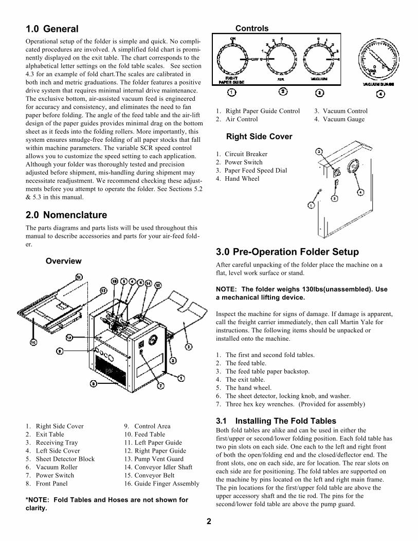
Overview
1. Right Side Cover 9. Control Area 2. Exit Table 10. Feed Table3. Receiving Tray 11. Left Paper Guide4. Left Side Cover 12. Right Paper Guide5. Sheet Detector Block 13. Pump Vent Guard6. Vacuum Roller 14. Conveyor Idler Shaft7. Power Switch 15. Conveyor Belt8. Front Panel 16. Guide Finger Assembly
*NOTE: Fold Tables and Hoses are not shown forclarity.
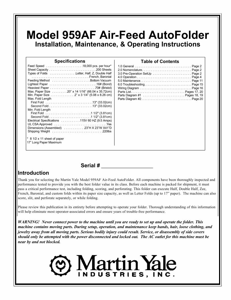
Controls
1. Right Paper Guide Control 3. Vacuum Control2. Air Control 4. Vacuum Gauge
Right Side Cover
1. Circuit Breaker 2. Power Switch3. Paper Feed Speed Dial4. Hand Wheel
3.0 Pre-Operation Folder SetupAfter careful unpacking of the folder place the machine on aflat, level work surface or stand.
NOTE: The folder weighs 130lbs(unassembled). Usea mechanical lifting device.
Inspect the machine for signs of damage. If damage is apparent,call the freight carrier immediately, then call Martin Yale forinstructions. The following items should be unpacked orinstalled onto the machine.
1. The first and second fold tables.2. The feed table. 3. The feed table paper backstop.4. The exit table.5. The hand wheel.6. The sheet detector, locking knob, and washer.7. Three hex key wrenches. (Provided for assembly)
3.1 Installing The Fold TablesBoth fold tables are alike and can be used in either thefirst/upper or second/lower folding position. Each fold table hastwo pin slots on each side. One each to the left and right frontof both the open/folding end and the closed/deflector end. Thefront slots, one on each side, are for location. The rear slots oneach side are for positioning. The fold tables are supported onthe machine by pins located on the left and right main frame.The pin locations for the first/upper fold table are above theupper accessory shaft and the tie rod. The pins for thesecond/lower fold table are above the pump guard.
2
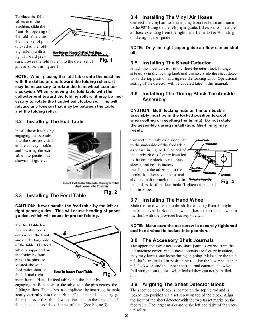
To place the foldtables onto themachine, slide thefront slot opening ofthe fold table ontothe inner set of pins(closest to the fold-ing rollers) with alight forward pres-sure. Lower the fold table onto the outer set ofpins as shown in Figure 1.
NOTE: When placing the fold table onto the machinewith the deflector end toward the folding rollers, itmay be necessary to rotate the handwheel counter-clockwise. When removing the fold table with thedeflector end toward the folding rollers, it may be nec-essary to rotate the handwheel clockwise. This willrelease any tension that may be between the tableand the folding roller.
3.2 Installing The Exit Table
Install the exit table byengaging the two tabsinto the slots provided on the conveyor table and lowering the exittable into position asshown in Figure 2.
3.3 Installing The Feed Table
CAUTION: Never handle the feed table by the left orright paper guides. This will cause bending of paperguides, which will cause improper folding.
The feed table hasfour location slots,one each at the frontand on the long sideof the table. The feedtable is supported onthe folder by fourpins. The pins arelocated above thefeed roller shaft onthe left and rightmain frame. Place the feed table onto the folder byengaging the front slots on the table with the pins nearest thefolding rollers. This is best accomplished by inserting the tablenearly vertically into the machine. Once the table slots engagethe pins, lower the table down so the slots on the long side ofthe table slide over the other set of pins (See Figure 3).
3.4 Installing The Vinyl Air HosesConnect the vinyl air hose extending from the left main frameto the 90° fitting on the left paper guide. Likewise, connect theair hose extending from the right main frame to the 90° fittingon the right paper guide.
NOTE: Only the right paper guide air flow can be shutoff.
3.5 Installing The Sheet DetectorAttach the sheet detector to the sheet detector block (orangeside out) via the locking knob and washer. Slide the sheet detec-tor to the top position and tighten the locking knob. Operationalsetting of the detector will be covered later in this manual.
3.6 Installing The Timing Block TurnbuckleAssembly
CAUTION: Both locking nuts on the turnbuckleassembly must be in the locked position (exceptwhen setting or resetting the timing). Do not rotatethe assembly during installation. Mis-timing mayresult.
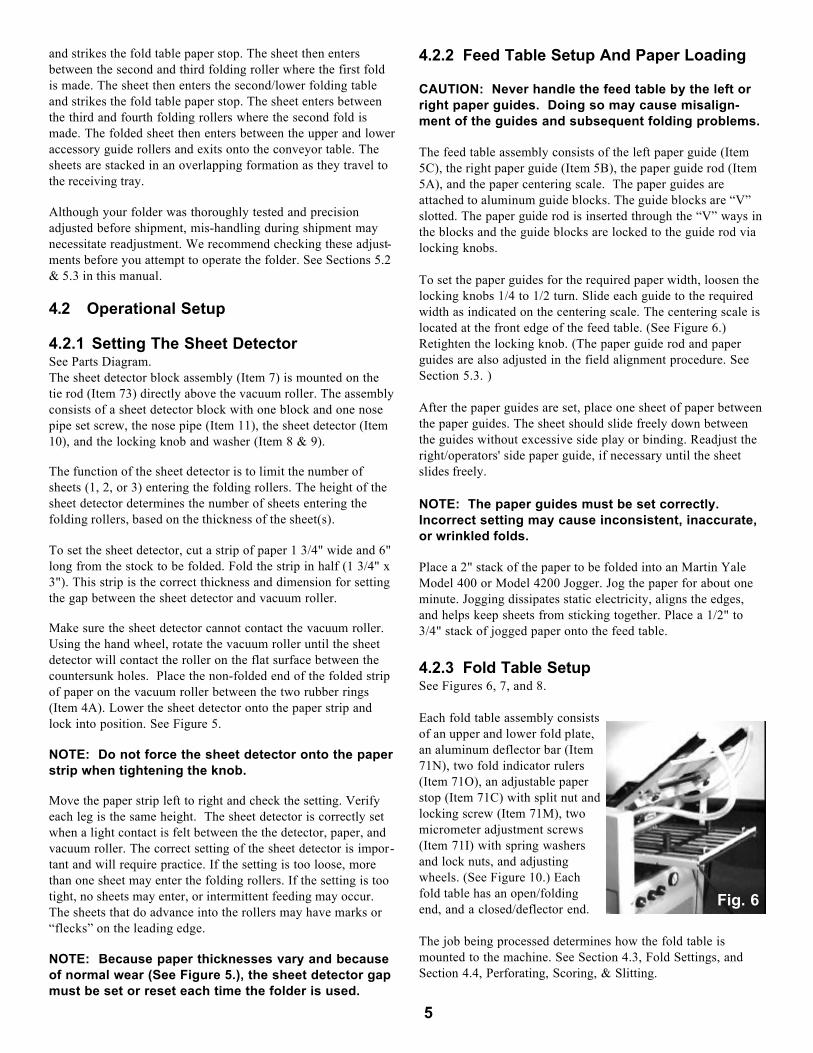
Connect the turnbuckle assemblyto the underside of the feed tableas shown in Figure 4. One end ofthe turnbuckle is factory installedto the timing block. A nut, brasssleeve, and bolt is factoryinstalled to the other end of theturnbuckle. Remove the nut andslide the bolt through the hole inthe underside of the feed table. Tighten the nut andbolt in place.
3.7 Installing The Hand WheelSlide the hand wheel onto the shaft extending from the rightmachine cover. Lock the handwheel (hex socket) set screw ontothe shaft with the provided hex key wrench.
NOTE: Make sure the set screw is securely tightenedand hand wheel is locked into position.
3.8 The Accessory Shaft JournalsThe upper and lower accessory shaft journals extend from theleft machine cover. While these journals are factory installed,they may have come loose during shipping. Make sure the jour-nal shafts are locked in position by rotating the lower shaft jour-nal clockwise, and the upper shaft journal counterclockwise.Pull straight out to test. when locked they can not be pulledout.
3.9 Aligning The Sheet Detector BlockThe sheet detector block is located on the top tie rod and islocked into position via a set screw on top of the block. Alignthe front of the sheet detector with the two target marks on thefeed table. The target marks are to the left and right of the vacu-um roller.
3
Fig. 1
Fig. 2
Fig. 3
Fig. 4

NOTE: When aligning the sheet detector to the targetmarks, look straight down on the target marks andthe edge of the paper. Do not look from an angle, orthe alignment will not be correct. Correct alignment isnecessary for efficient paper feeding.
To align the sheet detector block, follow this procedure.1. Loosen the set screw in the sheet detector block.2. Rotate the block toward the front of the machine until the
front (orange side) of the sheet detector is in approximatealignment with the target marks.
3. Place a sheet of paper onto the feed table.4. Align the sheet detector block so the sheet detector tips are
centered laterally over the left and right countersunk holesin the vacuum roller.
5. Rotate the hand wheel until the vacuum roller is positionedso the tips of the detector rest on the flat surface part of theroller, between the countersunk vacuum holes (when thedetector is lowered).
6. Loosen the detector locking knob, lower the detector until ittouches the round part of the wheel, and lock the detectorlocking knob.
7. Slide the sheet ofpaper down thefeed table until theleading edge isaligned with thetarget marks.
8. Move the sheetdetector block untilthe sheet detectorjust touches thepaper. See Fig. 5
9. Tighten the setscrew in the detec-tor block.
10. Push the sheetdetector to the topposition and lock the detector locking knob.
3.10 Setting The Guide FingersThere are two guide finger assemblies, one each to the left andright of the sheet detector block assembly. To set the guide fin-ger assemblies, follow this procedure:1. Unlock the set screw in the locking collar and move each
assembly to approximately three inches away from thedetector block. Center fingers on paper guides.
2. Rotate the guide finger toward the front until the bottom ofthe guide clears the surface of the feed table.
3. Align the long part of the guide (attached to the locking col-lar) so it is 90° to the surface of the feed table.
4. The bottom of the paper guides should clear the surface ofthe feed table paper guides by 1/32". See Section 5.2.2.
NOTE: Failure to correctly set the guides may causefeeding problems or smudging.
3.11 Connecting Electrical Power
WARNING! Never connect power to the machine until youare ready to set up and operate the folder. This machine con-tains moving parts. During setup, operation, and maintenancekeep hands, hair, loose clothing, and jewelry away from allmoving parts. Serious bodily injury could result. Machine requires 115 VAC 15amp. dedicated circuit. Beforeconnecting the folder power cord to a dedicated electrical outletof the appropriate voltage, be sure the speed control and pumpmotor switches are in the off position. Plug the folder powercord into an electrical outlet of the appropriate voltage andamperage.
CAUTION: Do not use extension cords. Be sure thefolder is connected to an outlet of the appropriatevoltage and amperage. Also make sure there are noother electrical appliances on the same electrical line.Failure to observe these precautions may causeinconsistent folding or machine malfunction.
3.12 Power Check And Test RunTo activate the machine, turn on the speed control switch.Rotate the variable speed control clockwise to the number 3 onthe speed control scale. Let the machine run a few minutes.During this initial run, and after any extended period of folderinactivity, you may hear a muted thumping sound. The sound isthe result of small, flat areas that form on the folding rollers atthe contact point. This process is a normal occurrence and willdisappear after a few minutes of running.
NOTE: You must let the folder run a few minutes afterlong periods of inactivity. Failure to do so may causeinconsistent folding.
Activate the pump motor switch. Basic setup of the folder isnow complete. However, you must complete the operationalsetup section before attempting to fold paper.
4.0 OperationWARNING! Never connect power to the machine until youare ready to set up and operate the folder. This machine con-tains moving parts. During setup, operation, and maintenancekeep hands, hair, loose clothing, and jewelry away from allmoving parts. Serious bodily injury could result.
4.1 How Paper Is Folded On The FolderWhen the folder has been correctly adjusted and set up, paperstock to be folded is placed onto the feed table.
The pump switch is turned on and the air flow is adjusted so thepaper stock is lifted slightly from the feed table. The speed con-trol is turned on and a folding speed is selected. The vacuumvalve is turned slowly clockwise until single sheets are forward-ed into the folding rollers.The following procedure describes how a letter fold is made.The feed system advances a sheet between the first and secondfolding rollers. The sheet then enters the first/upper fold table
4
Fig. 5
and strikes the fold table paper stop. The sheet then entersbetween the second and third folding roller where the first foldis made. The sheet then enters the second/lower folding tableand strikes the fold table paper stop. The sheet enters betweenthe third and fourth folding rollers where the second fold ismade. The folded sheet then enters between the upper and loweraccessory guide rollers and exits onto the conveyor table. Thesheets are stacked in an overlapping formation as they travel tothe receiving tray.
Although your folder was thoroughly tested and precisionadjusted before shipment, mis-handling during shipment maynecessitate readjustment. We recommend checking these adjust-ments before you attempt to operate the folder. See Sections 5.2& 5.3 in this manual.
4.2 Operational Setup
4.2.1 Setting The Sheet DetectorSee Parts Diagram.The sheet detector block assembly (Item 7) is mounted on thetie rod (Item 73) directly above the vacuum roller. The assemblyconsists of a sheet detector block with one block and one nosepipe set screw, the nose pipe (Item 11), the sheet detector (Item10), and the locking knob and washer (Item 8 & 9).
The function of the sheet detector is to limit the number ofsheets (1, 2, or 3) entering the folding rollers. The height of thesheet detector determines the number of sheets entering thefolding rollers, based on the thickness of the sheet(s).
To set the sheet detector, cut a strip of paper 1 3/4" wide and 6"long from the stock to be folded. Fold the strip in half (1 3/4" x3"). This strip is the correct thickness and dimension for settingthe gap between the sheet detector and vacuum roller.
Make sure the sheet detector cannot contact the vacuum roller.Using the hand wheel, rotate the vacuum roller until the sheetdetector will contact the roller on the flat surface between thecountersunk holes. Place the non-folded end of the folded stripof paper on the vacuum roller between the two rubber rings(Item 4A). Lower the sheet detector onto the paper strip andlock into position. See Figure 5.
NOTE: Do not force the sheet detector onto the paperstrip when tightening the knob.
Move the paper strip left to right and check the setting. Verifyeach leg is the same height. The sheet detector is correctly setwhen a light contact is felt between the the detector, paper, andvacuum roller. The correct setting of the sheet detector is impor-tant and will require practice. If the setting is too loose, morethan one sheet may enter the folding rollers. If the setting is tootight, no sheets may enter, or intermittent feeding may occur.The sheets that do advance into the rollers may have marks or“flecks” on the leading edge.
NOTE: Because paper thicknesses vary and becauseof normal wear (See Figure 5.), the sheet detector gapmust be set or reset each time the folder is used.
4.2.2 Feed Table Setup And Paper Loading
CAUTION: Never handle the feed table by the left orright paper guides. Doing so may cause misalign-ment of the guides and subsequent folding problems.
The feed table assembly consists of the left paper guide (Item5C), the right paper guide (Item 5B), the paper guide rod (Item5A), and the paper centering scale. The paper guides areattached to aluminum guide blocks. The guide blocks are “V”slotted. The paper guide rod is inserted through the “V” ways inthe blocks and the guide blocks are locked to the guide rod vialocking knobs.
To set the paper guides for the required paper width, loosen thelocking knobs 1/4 to 1/2 turn. Slide each guide to the requiredwidth as indicated on the centering scale. The centering scale islocated at the front edge of the feed table. (See Figure 6.)Retighten the locking knob. (The paper guide rod and paperguides are also adjusted in the field alignment procedure. SeeSection 5.3. )
After the paper guides are set, place one sheet of paper betweenthe paper guides. The sheet should slide freely down betweenthe guides without excessive side play or binding. Readjust theright/operators' side paper guide, if necessary until the sheetslides freely.
NOTE: The paper guides must be set correctly.Incorrect setting may cause inconsistent, inaccurate,or wrinkled folds.
Place a 2" stack of the paper to be folded into an Martin YaleModel 400 or Model 4200 Jogger. Jog the paper for about oneminute. Jogging dissipates static electricity, aligns the edges,and helps keep sheets from sticking together. Place a 1/2" to3/4" stack of jogged paper onto the feed table.
4.2.3 Fold Table Setup See Figures 6, 7, and 8.
Each fold table assembly consistsof an upper and lower fold plate,an aluminum deflector bar (Item71N), two fold indicator rulers(Item 71O), an adjustable paperstop (Item 71C) with split nut andlocking screw (Item 71M), twomicrometer adjustment screws(Item 71I) with spring washersand lock nuts, and adjustingwheels. (See Figure 10.) Eachfold table has an open/foldingend, and a closed/deflector end.
The job being processed determines how the fold table ismounted to the machine. See Section 4.3, Fold Settings, andSection 4.4, Perforating, Scoring, & Slitting.
5
Fig. 6

The position of the foldtable paper stop deter-mines the location of eachfold in the paper. The sim-plified fold chart (Item64A) located on the exittable (Item 64) providespaper stop settings for fivestandard cut paper sizes.Two are metric (A3 &A4), and three are inch (81/2 x 11, 8 1/2 x 14, 11 x17).
The fold chart refers to “1st”, which corresponds to paper stopsettings on the first/upper fold table, and “2nd”, which corre-sponds to paper stop settings on the second/lower fold table.The letters on the fold chart correspond to the letter position onthe fold indicator rulers. The paper stop pointers should be setso they bisect the circle of the appropriate letter setting.
Any paper size not shown on the fold chart up to 14" x 18" canbe set on the fold tables by following this procedure. Hand-foldthe sheet into the required fold. Measure the distance betweeneach fold. Set the paper stops on the first and second fold tablesaccording to measurements.
To position, or reposition the paper stop on the fold table,loosen the lockingknobs on top of thenylon split nut by twofull turns counter-clockwise. A springunder each split nuthelps disengage thesplit nut from themicrometer rodthreads. Place thethumb of your lefthand on top of the left locking knob and the thumb of your righthand on the right locking knob. With the index and middle fin-ger of each hand, grasp the split nut for control. Slide the paperstop assembly parallel along the micrometer rods to the requiredfold location/measurement. Release the split nut and retightenthe locking knob.
CAUTION: Make sure the split nut is correctlymeshed with the rod threads before locking into posi-tion. Failure to do so may damage the nut or threads.
Make fold corrections by loosening the locking knobs 1/4 to 1/2turn. Move the appropriate micrometer wheel in the directionindicated. Retighten the locking knob.
NOTE: Variations in folding speed will affect fold con-sistency. Make sure corrections are made at thespeed you intend to fold. If folding is interrupted,return the speed control to its previous position.Always clear the conveyor and exit table of foldedmaterial after an interruption. Failure to do so maycause stacking problems when folding is resumed.
4.2.4 Setup Of The Feed Table BackstopThe feed table backstop is a one inch angled aluminum fixturewith a magnetic strip attached to one side. The feed table back-stop should be used when processing 8 1/2" x 11" (A4) orsmaller stock to prevent sheets from being blown back from thevacuum roller. Place the magnetic side of the backstop on thefeed table so the vertical side is set against the tail (back) end ofthe paper stack.
4.2.5 Setup Of The Stacking Wheel AssemblyThe stacking wheel assembly is located at the rear/exit side ofthe folder. The function of the stacking wheels is to arrange theexiting material from the folder into an overlapping stream onthe conveyor table. Generally, the stacking wheels should bepositioned about one inch from the edge of the sheet after thesheet has dropped to the conveyor table.
NOTE: Increasing or decreasing folding speed mayrequire repositioning the stacking wheel assembly.
The assembly consists of the following. A square shaft with acompression spring on one side. An angled deflector plate isattached via two screws to the front of the square shaft. Thestacking wheel shaft extends outward from the center of thesquare shaft. Mounted on the stacking wheel shaft are the axlebox housing, the stacking wheel axle, two stacking wheelweights, and four stacking wheels.
There are two sets of stacking wheel assembly mounting holeslocated in the machine side frame, directly in front of the upperaccessory shaft. To mount the assembly, insert the spring end ofthe square shaft into one of the two holes in the side frame(operators' side). Apply pressure (pull) the square shaft laterallytoward the spring end of the shaft. As you do so, align the otherend of the square shaft with the corresponding hole in the otherside frame and release pressure.
To remove the stacking wheel assembly, apply pressure (pull)the square shaft laterally toward the spring end of the shaft.Doing so will pull the other end of the square shaft from theside frame. After the end is clear of the side frame, pull theentire assembly out of the machine.
For most folding jobs, the deflector plate faces upward. To helpeliminate nesting and to improve the stacking of short folds andheavier paper stocks, the deflector plate should be faced down-ward. To do so, remove and reverse (turn over) the stackingwheel assembly. The deflector plate can also be fine adjusted byloosening the two mounting screws in the square shaft and low-ering the slotted deflector plate up to 1/8". When using thestripper wire the deflector plate must be removed and the stack-ing wheel assembly should be installed in the inner set of holes.
The stacking wheel hook is located on the 1/2" tie rod, belowthe first/upper fold table. Use of the hook is necessary whenperforating, scoring, or slitting sheets longer than 12". Simplyrest the stacking wheel shaft in the curved section of the hook.
6
Fig. 7
Fig. 8
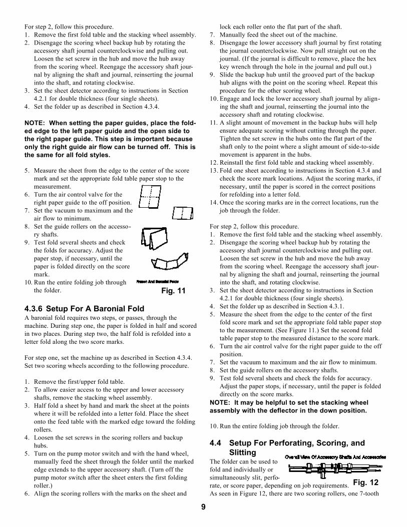
4.2.6 The Simplified Fold ChartThe simplified fold chart located on the exit table providespaper stop settings for five standard cut paper sizes. Two aremetric (A3 & A4), and three are inch (8 1/2 x 11, 8 1/2 x 14, 11x 17). The four most popular folds (letter, “Z”, double half, andhalf) are illustrated.
The fold chart refers to “1st”, which corresponds to paper stopsettings on the first fold table, and “2nd”, which corresponds topaper stop settings on the second fold table. The letters on thefold chart correspond to the letter position on the fold indicatorrulers. The paper stop pointers should be set so they bisect thecircle of the appropriate letter setting.
NOTE: To avoid confusion, the fold chart indicates allhalf folds should be made on the second fold table.However, half folds can be made on either fold table,depending on the weight of the paper being folded.Generally, lighter weight stocks should be folded withthe first/upper fold table and heavier stocks with thesecond/lower fold table. (See Section 4.2.3.)
Any paper size not shown on the fold chart up to 14" x 18" canbe set on the fold tables by following this procedure. Hand-foldthe sheet into the required fold. Measure the distance betweeneach fold. Set the paper stops on the first and second fold tablesaccording to measurements.
4.2.7 The Speed ControlThe speed control is an SCR type control that converts alternat-ing current (AC) to direct current (DC). The folding motor ofthe folder is powered by direct current. The speed control is acombination on/off switch and variable speed regulator. Thecontrol is mounted on the upper left corner of the right (opera-tors') side cover. To activate the feed system of the folder, turnthe speed control clockwise. To incrementally increase the feedspeed, continue to turn the speed control clockwise. To decreasethe feed speed, turn the speed control counterclockwise. Todeactivate the feed system, turn the speed control counterclock-wise until it stops.
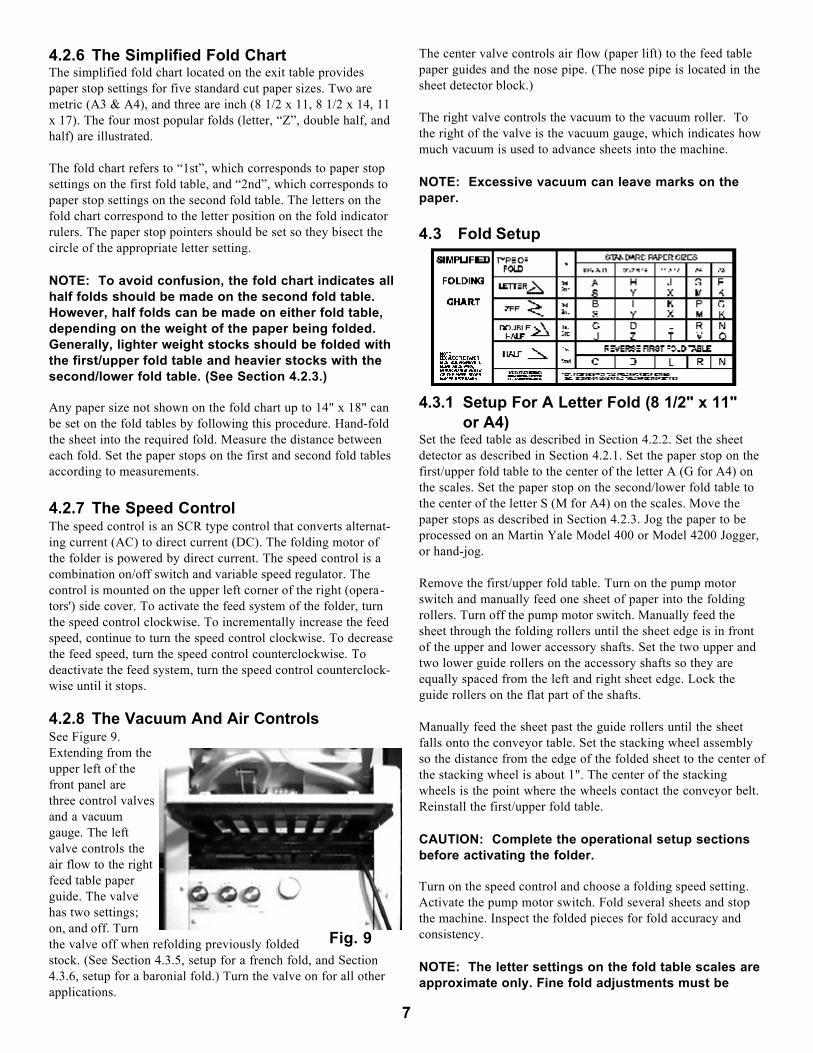
4.2.8 The Vacuum And Air ControlsSee Figure 9.Extending from theupper left of thefront panel arethree control valvesand a vacuumgauge. The leftvalve controls theair flow to the rightfeed table paperguide. The valvehas two settings;on, and off. Turnthe valve off when refolding previously foldedstock. (See Section 4.3.5, setup for a french fold, and Section4.3.6, setup for a baronial fold.) Turn the valve on for all otherapplications.
The center valve controls air flow (paper lift) to the feed tablepaper guides and the nose pipe. (The nose pipe is located in thesheet detector block.)
The right valve controls the vacuum to the vacuum roller. Tothe right of the valve is the vacuum gauge, which indicates howmuch vacuum is used to advance sheets into the machine.
NOTE: Excessive vacuum can leave marks on thepaper.
4.3 Fold Setup
4.3.1 Setup For A Letter Fold (8 1/2" x 11"or A4)
Set the feed table as described in Section 4.2.2. Set the sheetdetector as described in Section 4.2.1. Set the paper stop on thefirst/upper fold table to the center of the letter A (G for A4) onthe scales. Set the paper stop on the second/lower fold table tothe center of the letter S (M for A4) on the scales. Move thepaper stops as described in Section 4.2.3. Jog the paper to beprocessed on an Martin Yale Model 400 or Model 4200 Jogger,or hand-jog.
Remove the first/upper fold table. Turn on the pump motorswitch and manually feed one sheet of paper into the foldingrollers. Turn off the pump motor switch. Manually feed thesheet through the folding rollers until the sheet edge is in frontof the upper and lower accessory shafts. Set the two upper andtwo lower guide rollers on the accessory shafts so they areequally spaced from the left and right sheet edge. Lock theguide rollers on the flat part of the shafts.
Manually feed the sheet past the guide rollers until the sheetfalls onto the conveyor table. Set the stacking wheel assemblyso the distance from the edge of the folded sheet to the center ofthe stacking wheel is about 1". The center of the stackingwheels is the point where the wheels contact the conveyor belt.Reinstall the first/upper fold table.
CAUTION: Complete the operational setup sectionsbefore activating the folder.
Turn on the speed control and choose a folding speed setting.Activate the pump motor switch. Fold several sheets and stopthe machine. Inspect the folded pieces for fold accuracy andconsistency.
NOTE: The letter settings on the fold table scales areapproximate only. Fine fold adjustments must be
7
Fig. 9

made with the micro adjustment wheels. This is thesame for all fold styles. See Fig. 10
When the feedtable paperguides are cor-rectly set and aconsistent foldspeed is main-tained, the fold-ed material willexit the machineconsistently.After the neces-sary correctionsare made, complete the folding job.
4.3.2 Setup For A Z Fold (8 1/2" x 11" or A4)NOTE: The setup for this fold is identical to 4.3.1 except forthe positioning of the paper stop on the fold table.Set the feed table as described in Section 4.2.2. Set the sheetdetector as described in Section 4.2.1. Set the paper stop on thefirst/upper fold table to the center of the letter B (P for A4) onthe scales. Set the paper stop on the second/lower fold table tothe center of the letter S (M for A4) on the scales. Move thepaper stops as described in Section 4.2.3. Jog the paper to beprocessed on an Martin Yale Model 400 or 4200 Jogger, or handjog.
4.3.3 Setup For A Double Half Fold (11" x17" or A3)
NOTE: The setup for this fold is identical to 4.3.1 except forthe positioning of the paper stop on the fold table.Set the feed table as described in Section 4.2.2. Set the sheetdetector as described in Section 4.2.1. Set the paper stop on thefirst/upper fold table to the center of the letter L (N for A3) onthe scales. Set the paper stops on the second/lower fold table tothe center of the letter T (Q for A3) on the scales. Move thepaper stops as described in Section 4.2.3. Jog the paper to beprocessed on an Martin Yale Model 400 or 4200 Jogger, or handjog.
4.3.4 Setup For A Half Fold (Single Fold)(8 1/2" x 11" or A4)
If your wish to score, slit, or perforate the half fold, see Section4.4 for instructions.
Insert the first fold table into position with the folding (open)end toward the fold rollers. The second fold table is placed intoposition with the deflecting (closed) end toward the fold rollers.Set the paper stop on the first fold table to the setting as shownon the folding chart.
NOTE: Although half folds can be made with eitherfold table, the first fold table provides better accuracyon regular and lightweight paper stocks. However, toreduce crushed folds and to minimize curl whenheavier stock is folded, utilize the second fold table.
For any sheet size not listed on the fold chart, fold the sheet inhalf by hand. Measure the sheet to the fold. Set the paper stopaccording to the measurement.
NOTE: The setup for this fold is identical to 4.3.1 except forthe positioning of the paper stop on the fold table.Set up the feed table according to Section 4.2.2. Set the sheetdetector as described in Section 4.2.1. Jog the paper to beprocessed on an Martin Yale Model 400 or Model 4200 Jogger,or hand-jog.
4.3.5 Setup For A French FoldA french fold requires two steps, or passes, through themachine. During step one, the paper is folded in half andscored. During step two, the sheet is folded in half again at thescore mark. Also see Section 4.4.For step one, set up the machine according to instructions inSection 4.3.4. Set one scoring roller according to the followingprocedure.1. Remove the first/upper fold table. 2. To allow easier access to the upper and lower accessory
shafts, remove the stacking wheel assembly. 3. Half fold a sheet by hand and mark the sheet at the point of
the fold. Place the sheet onto the feed table with the markededge toward the folding rollers.
4. Loosen the set screws in the scoring roller and backup hub.5. Turn on the pump motor switch and with the hand wheel,
manually feed the sheet through the folder until the markededge extends to the upper accessory shaft. (Turn off thepump motor switch after the sheet enters the first foldingroller.)
6. Align the scoring roller with the mark on the sheet and lockthe roller onto the flat part of the shaft.
7. Manually feed the sheet out of the machine.8. Disengage the lower accessory shaft journal by first rotating
the journal counterclockwise. Now pull straight out on thejournal. (If the journal is difficult to remove, place the hexkey wrench through the hole in the journal and pull out.)
9. Slide the backup hub until the grooved part of the backuphub aligns with the point on the scoring wheel.
10. Engage and lock the lower accessory shaft journal by align-ing the shaft and journal, reinserting the journal into theaccessory shaft, and rotating clockwise.
11. A slight amount of movement in the backup hub will helpensure adequate scoring without cutting through the paper.Tighten the set screw in the hub onto the flat part of theshaft only to the point where a slight amount of side-to-sidemovement is apparent in the hub.
12. Reinstall the first fold table and stacking wheel assembly.13. Fold one sheet according to instructions in Section 4.3.4 and
check the score mark locations. Adjust the scoring wheel, ifnecessary, until the paper is scored in the correct position forrefolding.
NOTE: If the paper is cut through during the scoringprocess, round off the point of the scoring roller witha fine file or emery.
14. Once the scoring mark is in the correct location, run the jobthrough the folder.
8
Fig. 10
For step 2, follow this procedure.1. Remove the first fold table and the stacking wheel assembly.2. Disengage the scoring wheel backup hub by rotating the
accessory shaft journal counterclockwise and pulling out.Loosen the set screw in the hub and move the hub awayfrom the scoring wheel. Reengage the accessory shaft jour-nal by aligning the shaft and journal, reinserting the journalinto the shaft, and rotating clockwise.
3. Set the sheet detector according to instructions in Section4.2.1 for double thickness (four single sheets).
4. Set the folder up as described in Section 4.3.4.
NOTE: When setting the paper guides, place the fold-ed edge to the left paper guide and the open side tothe right paper guide. This step is important becauseonly the right guide air flow can be turned off. This isthe same for all fold styles.
5. Measure the sheet from the edge to the center of the scoremark and set the appropriate fold table paper stop to themeasurement.
6. Turn the air control valve for theright paper guide to the off position.
7. Set the vacuum to maximum and theair flow to minimum.
8. Set the guide rollers on the accesso-ry shafts.
9. Test fold several sheets and checkthe folds for accuracy. Adjust thepaper stop, if necessary, until thepaper is folded directly on the scoremark.
10. Run the entire folding job throughthe folder.
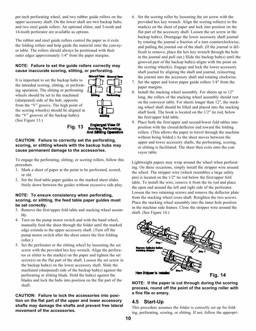
4.3.6 Setup For A Baronial FoldA baronial fold requires two steps, or passes, through themachine. During step one, the paper is folded in half and scoredin two places. During step two, the half fold is refolded into aletter fold along the two score marks.
For step one, set the machine up as described in Section 4.3.4.Set two scoring wheels according to the following procedure.
1. Remove the first/upper fold table.2. To allow easier access to the upper and lower accessory
shafts, remove the stacking wheel assembly. 3. Half fold a sheet by hand and mark the sheet at the points
where it will be refolded into a letter fold. Place the sheetonto the feed table with the marked edge toward the foldingrollers.
4. Loosen the set screws in the scoring rollers and backuphubs.
5. Turn on the pump motor switch and with the hand wheel,manually feed the sheet through the folder until the markededge extends to the upper accessory shaft. (Turn off thepump motor switch after the sheet enters the first foldingroller.)
6. Align the scoring rollers with the marks on the sheet and
lock each roller onto the flat part of the shaft.7. Manually feed the sheet out of the machine.8. Disengage the lower accessory shaft journal by first rotating
the journal counterclockwise. Now pull straight out on thejournal. (If the journal is difficult to remove, place the hexkey wrench through the hole in the journal and pull out.)
9. Slide the backup hub until the grooved part of the backuphub aligns with the point on the scoring wheel. Repeat thisprocedure for the other scoring wheel.
10. Engage and lock the lower accessory shaft journal by align-ing the shaft and journal, reinserting the journal into theaccessory shaft and rotating clockwise.
11. A slight amount of movement in the backup hubs will helpensure adequate scoring without cutting through the paper.Tighten the set screw in the hubs onto the flat part of theshaft only to the point where a slight amount of side-to-sidemovement is apparent in the hubs.
12. Reinstall the first fold table and stacking wheel assembly.13. Fold one sheet according to instructions in Section 4.3.4 and
check the score mark locations. Adjust the scoring marks, ifnecessary, until the paper is scored in the correct positionsfor refolding into a letter fold.
14. Once the scoring marks are in the correct locations, run thejob through the folder.
For step 2, follow this procedure.1. Remove the first fold table and the stacking wheel assembly.2. Disengage the scoring wheel backup hub by rotating the
accessory shaft journal counterclockwise and pulling out.Loosen the set screw in the hub and move the hub awayfrom the scoring wheel. Reengage the accessory shaft jour-nal by aligning the shaft and journal, reinserting the journalinto the shaft, and rotating clockwise.
3. Set the sheet detector according to instructions in Section4.2.1 for double thickness (four single sheets).
4. Set the folder up as described in Section 4.3.1. 5. Measure the sheet from the edge to the center of the first
fold score mark and set the appropriate fold table paper stopto the measurement. (See Figure 11.) Set the second foldtable paper stop to the measured distance to the score mark.
6. Turn the air control valve for the right paper guide to the offposition.
7. Set the vacuum to maximum and the air flow to minimum.8. Set the guide rollers on the accessory shafts.9. Test fold several sheets and check the folds for accuracy.
Adjust the paper stops, if necessary, until the paper is foldeddirectly on the score marks.
NOTE: It may be helpful to set the stacking wheelassembly with the deflector in the down position.
10. Run the entire folding job through the folder.
4.4 Setup For Perforating, Scoring, andSlitting
The folder can be used tofold and individually orsimultaneously slit, perfo-rate, or score paper, depending on job requirements.As seen in Figure 12, there are two scoring rollers, one 7-tooth
9
Fig. 11
Fig. 12
per-inch perforating wheel, and two rubber guide rollers on theupper accessory shaft. On the lower shaft are two backup hubs,and two steel guide rollers. An optional slitter, and 3-tooth and14-tooth perforator are available as options.
The rubber and steel guide rollers control the paper as it exitsthe folding rollers and help guide the material onto the convey-or table. The rollers should always be positioned with theirouter edges approximately 1/4" from the paper margins.
NOTE: Failure to set the guide rollers correctly maycause inaccurate scoring, slitting, or perforating.
It is important to set the backup hubs tothe intended scoring, slitting, or perforat-ing operation. The slitting or perforatingwheels should be set to the machined(sharpened) side of the hub, oppositefrom the “V” groove. The high point ofthe scoring wheel(s) should be aligned inthe “V” grooves of the backup hub(s).(See Figure 13.)
CAUTION: Failure to correctly set the perforating,scoring, or slitting wheels with the backup hubs maycause permanent damage to the accessories.
To engage the perforating, slitting, or scoring rollers, follow thisprocedure.1. Mark a sheet of paper at the point to be perforated, scored,
or slit.2. Set the feed table paper guides so the marked sheet slides
freely down between the guides without excessive side play.
NOTE: To ensure consistency when perforating,scoring, or slitting, the feed table paper guides mustbe set correctly.3. Remove the first/upper fold table and stacking wheel assem-
bly.4. Turn on the pump motor switch and with the hand wheel,
manually feed the sheet through the folder until the markededge extends to the upper accessory shaft. (Turn off thepump motor switch after the sheet enters the first foldingroller.)
5. Set the perforator or the slitting wheel by loosening the setscrew with the provided hex key wrench. Align the perfora-tor or slitter to the mark(s) on the paper and tighten the setscrew(s) on the flat part of the shaft. Loosen the set screw inthe backup hub(s) on the lower accessory shaft. Slide themachined (sharpened) side of the backup hub(s) against theperforating or slitting blade. Hold the hub(s) against theblades and lock the hubs into position on the flat part of theshaft.
CAUTION: Failure to lock the accessories into posi-tion on the flat part of the upper and lower accessoryshafts may damage the shafts and prevent free lateralmovement of the accessories.
6. Set the scoring roller by loosening the set screw with theprovided hex key wrench. Align the scoring roller(s) to themark(s) on the sheet of paper and lock into position on theflat part of the accessory shaft. Loosen the set screw in thebackup hub(s). Disengage the lower accessory shaft journalby rotating the journal a fraction of a turn counterclockwise,and pulling the journal out of the shaft. (If the journal is dif-ficult to remove, place the hex key wrench through the holein the journal and pull out.) Slide the backup hub(s) until thegrooved part of the backup hub(s) aligns with the point onthe scoring wheel(s). Engage and lock the lower accessoryshaft journal by aligning the shaft and journal, reinsertingthe journal into the accessory shaft and rotating clockwise.
7. Set the upper and lower paper guide rollers 1/4" from thepaper margins.
8. Install the stacking wheel assembly. For sheets up to 12"long, the rollers of the stacking wheel assembly should reston the conveyor table. For sheets longer than 12", the stack-ing wheel shaft should be lifted and placed into the stackingshaft hook. The hook is located on the 1/2" tie rod, belowthe first/upper fold table.
9. Place both the first/upper and second/lower fold tables intoposition with the closed/deflector end toward the foldingrollers. (This allows the paper to travel through the machinewithout being folded.) As the sheet moves between theupper and lower accessory shafts, the perforating, scoring,or slitting is facilitated. The sheet then exits onto the con-veyor table.
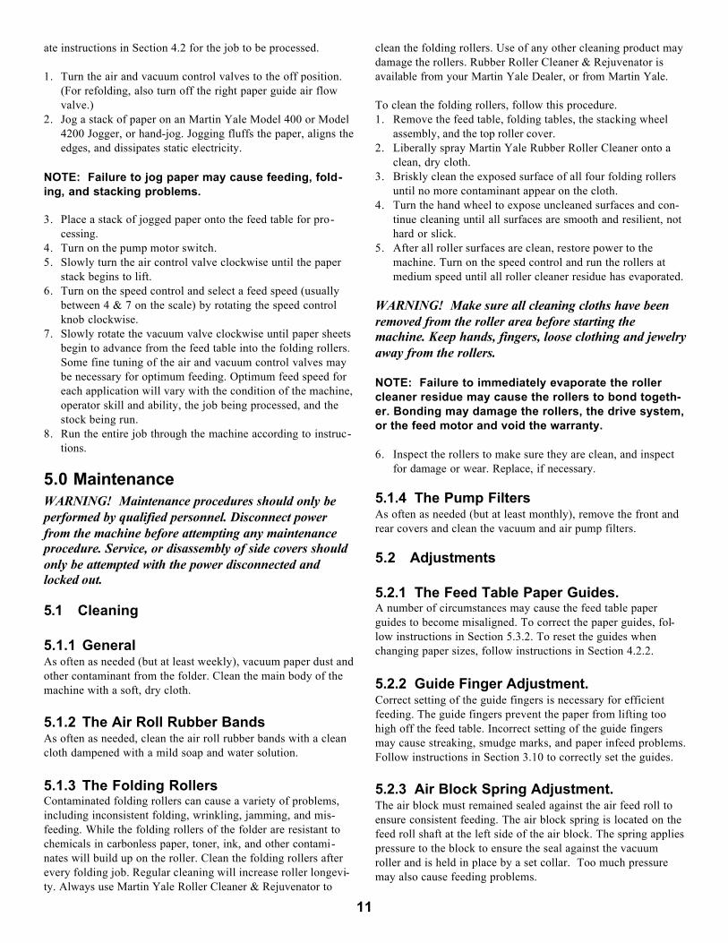
Lightweight papers may wrap around the wheel when perforat-ing. On these occasions, simply install the stripper wire aroundthe wheel. The stripper wire (which resembles a large safetypin) is located on the 1/2" tie rod below the first/upper foldtable. To install the wire, remove it from the tie rod and placethe open end around the left and right side of the perforator.Loosen the two retaining screws and remove the deflector platefrom the stacking wheel cross shaft. Retighten the two screws.Place the stacking wheel assembly into the inner hole positionin the machine side frames. Close the stripper wire around theshaft. (See Figure 14.)
NOTE: If the paper is cut through during the scoringprocess, round off the point of the scoring roller witha fine file or emery.
4.5 Start-UpThis procedure assumes the folder is correctly set up for fold-ing, perforating, scoring, or slitting. If not, follow the appropri-
10
Fig. 14
Fig. 13
ate instructions in Section 4.2 for the job to be processed.
1. Turn the air and vacuum control valves to the off position.(For refolding, also turn off the right paper guide air flowvalve.)
2. Jog a stack of paper on an Martin Yale Model 400 or Model4200 Jogger, or hand-jog. Jogging fluffs the paper, aligns theedges, and dissipates static electricity.
NOTE: Failure to jog paper may cause feeding, fold-ing, and stacking problems.
3. Place a stack of jogged paper onto the feed table for pro-cessing.
4. Turn on the pump motor switch.5. Slowly turn the air control valve clockwise until the paper
stack begins to lift.6. Turn on the speed control and select a feed speed (usually
between 4 & 7 on the scale) by rotating the speed controlknob clockwise.
7. Slowly rotate the vacuum valve clockwise until paper sheetsbegin to advance from the feed table into the folding rollers.Some fine tuning of the air and vacuum control valves maybe necessary for optimum feeding. Optimum feed speed foreach application will vary with the condition of the machine,operator skill and ability, the job being processed, and thestock being run.
8. Run the entire job through the machine according to instruc-tions.
5.0 MaintenanceWARNING! Maintenance procedures should only beperformed by qualified personnel. Disconnect powerfrom the machine before attempting any maintenanceprocedure. Service, or disassembly of side covers shouldonly be attempted with the power disconnected andlocked out.
5.1 Cleaning
5.1.1 GeneralAs often as needed (but at least weekly), vacuum paper dust andother contaminant from the folder. Clean the main body of themachine with a soft, dry cloth.
5.1.2 The Air Roll Rubber BandsAs often as needed, clean the air roll rubber bands with a cleancloth dampened with a mild soap and water solution.
5.1.3 The Folding RollersContaminated folding rollers can cause a variety of problems,including inconsistent folding, wrinkling, jamming, and mis-feeding. While the folding rollers of the folder are resistant tochemicals in carbonless paper, toner, ink, and other contami-nates will build up on the roller. Clean the folding rollers afterevery folding job. Regular cleaning will increase roller longevi-ty. Always use Martin Yale Roller Cleaner & Rejuvenator to
clean the folding rollers. Use of any other cleaning product maydamage the rollers. Rubber Roller Cleaner & Rejuvenator isavailable from your Martin Yale Dealer, or from Martin Yale.
To clean the folding rollers, follow this procedure.1. Remove the feed table, folding tables, the stacking wheel
assembly, and the top roller cover.2. Liberally spray Martin Yale Rubber Roller Cleaner onto a
clean, dry cloth.3. Briskly clean the exposed surface of all four folding rollers
until no more contaminant appear on the cloth.4. Turn the hand wheel to expose uncleaned surfaces and con-
tinue cleaning until all surfaces are smooth and resilient, nothard or slick.
5. After all roller surfaces are clean, restore power to themachine. Turn on the speed control and run the rollers atmedium speed until all roller cleaner residue has evaporated.
WARNING! Make sure all cleaning cloths have beenremoved from the roller area before starting themachine. Keep hands, fingers, loose clothing and jewelryaway from the rollers.
NOTE: Failure to immediately evaporate the rollercleaner residue may cause the rollers to bond togeth-er. Bonding may damage the rollers, the drive system,or the feed motor and void the warranty.
6. Inspect the rollers to make sure they are clean, and inspectfor damage or wear. Replace, if necessary.
5.1.4 The Pump FiltersAs often as needed (but at least monthly), remove the front andrear covers and clean the vacuum and air pump filters.
5.2 Adjustments
5.2.1 The Feed Table Paper Guides.A number of circumstances may cause the feed table paperguides to become misaligned. To correct the paper guides, fol-low instructions in Section 5.3.2. To reset the guides whenchanging paper sizes, follow instructions in Section 4.2.2.
5.2.2 Guide Finger Adjustment.Correct setting of the guide fingers is necessary for efficientfeeding. The guide fingers prevent the paper from lifting toohigh off the feed table. Incorrect setting of the guide fingersmay cause streaking, smudge marks, and paper infeed problems.Follow instructions in Section 3.10 to correctly set the guides.
5.2.3 Air Block Spring Adjustment.The air block must remained sealed against the air feed roll toensure consistent feeding. The air block spring is located on thefeed roll shaft at the left side of the air block. The spring appliespressure to the block to ensure the seal against the vacuumroller and is held in place by a set collar. Too much pressuremay also cause feeding problems.
11
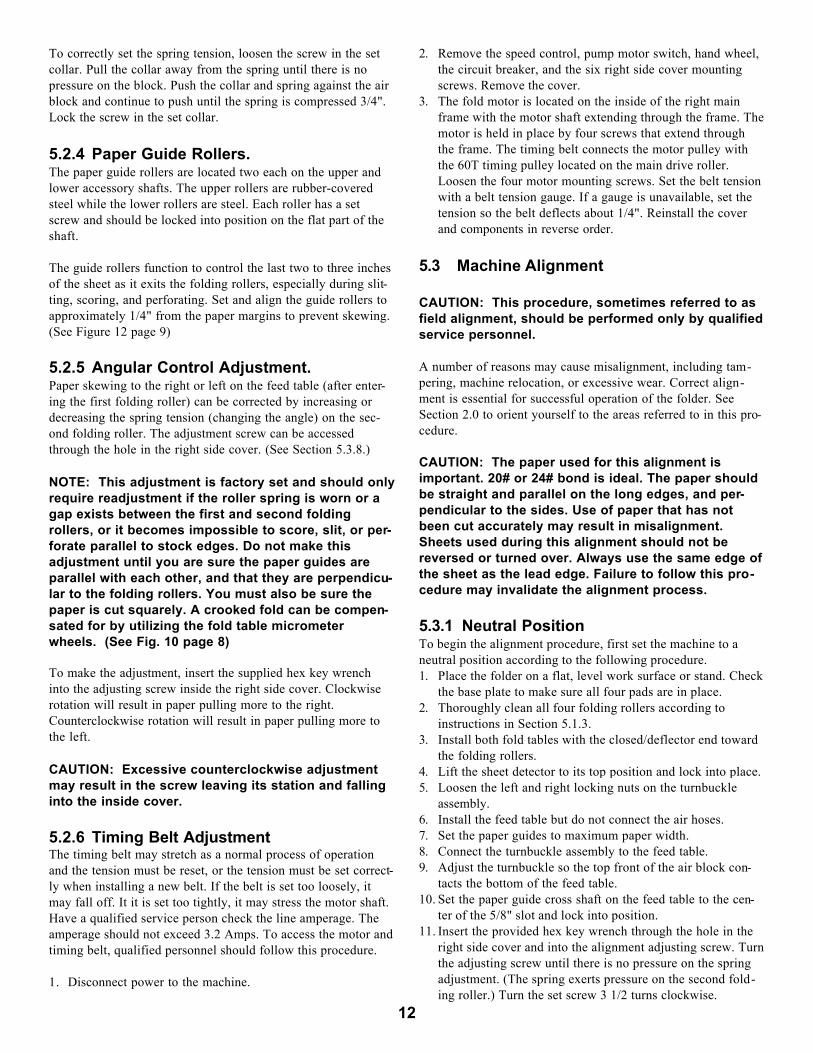
To correctly set the spring tension, loosen the screw in the setcollar. Pull the collar away from the spring until there is nopressure on the block. Push the collar and spring against the airblock and continue to push until the spring is compressed 3/4".Lock the screw in the set collar.
5.2.4 Paper Guide Rollers.The paper guide rollers are located two each on the upper andlower accessory shafts. The upper rollers are rubber-coveredsteel while the lower rollers are steel. Each roller has a setscrew and should be locked into position on the flat part of theshaft.
The guide rollers function to control the last two to three inchesof the sheet as it exits the folding rollers, especially during slit-ting, scoring, and perforating. Set and align the guide rollers toapproximately 1/4" from the paper margins to prevent skewing.(See Figure 12 page 9)
5.2.5 Angular Control Adjustment.Paper skewing to the right or left on the feed table (after enter-ing the first folding roller) can be corrected by increasing ordecreasing the spring tension (changing the angle) on the sec-ond folding roller. The adjustment screw can be accessedthrough the hole in the right side cover. (See Section 5.3.8.)
NOTE: This adjustment is factory set and should onlyrequire readjustment if the roller spring is worn or agap exists between the first and second foldingrollers, or it becomes impossible to score, slit, or per-forate parallel to stock edges. Do not make thisadjustment until you are sure the paper guides areparallel with each other, and that they are perpendicu-lar to the folding rollers. You must also be sure thepaper is cut squarely. A crooked fold can be compen-sated for by utilizing the fold table micrometerwheels. (See Fig. 10 page 8)
To make the adjustment, insert the supplied hex key wrenchinto the adjusting screw inside the right side cover. Clockwiserotation will result in paper pulling more to the right.Counterclockwise rotation will result in paper pulling more tothe left.
CAUTION: Excessive counterclockwise adjustmentmay result in the screw leaving its station and fallinginto the inside cover.
5.2.6 Timing Belt AdjustmentThe timing belt may stretch as a normal process of operationand the tension must be reset, or the tension must be set correct-ly when installing a new belt. If the belt is set too loosely, itmay fall off. It it is set too tightly, it may stress the motor shaft.Have a qualified service person check the line amperage. Theamperage should not exceed 3.2 Amps. To access the motor andtiming belt, qualified personnel should follow this procedure.
1. Disconnect power to the machine.
2. Remove the speed control, pump motor switch, hand wheel,the circuit breaker, and the six right side cover mountingscrews. Remove the cover.
3. The fold motor is located on the inside of the right mainframe with the motor shaft extending through the frame. Themotor is held in place by four screws that extend throughthe frame. The timing belt connects the motor pulley withthe 60T timing pulley located on the main drive roller.Loosen the four motor mounting screws. Set the belt tensionwith a belt tension gauge. If a gauge is unavailable, set thetension so the belt deflects about 1/4". Reinstall the coverand components in reverse order.
5.3 Machine Alignment
CAUTION: This procedure, sometimes referred to asfield alignment, should be performed only by qualifiedservice personnel.
A number of reasons may cause misalignment, including tam-pering, machine relocation, or excessive wear. Correct align-ment is essential for successful operation of the folder. SeeSection 2.0 to orient yourself to the areas referred to in this pro-cedure.
CAUTION: The paper used for this alignment isimportant. 20# or 24# bond is ideal. The paper shouldbe straight and parallel on the long edges, and per-pendicular to the sides. Use of paper that has notbeen cut accurately may result in misalignment.Sheets used during this alignment should not bereversed or turned over. Always use the same edge ofthe sheet as the lead edge. Failure to follow this pro-cedure may invalidate the alignment process.
5.3.1 Neutral PositionTo begin the alignment procedure, first set the machine to aneutral position according to the following procedure.1. Place the folder on a flat, level work surface or stand. Check
the base plate to make sure all four pads are in place.2. Thoroughly clean all four folding rollers according to
instructions in Section 5.1.3.3. Install both fold tables with the closed/deflector end toward
the folding rollers.4. Lift the sheet detector to its top position and lock into place.5. Loosen the left and right locking nuts on the turnbuckle
assembly.6. Install the feed table but do not connect the air hoses.7. Set the paper guides to maximum paper width.8. Connect the turnbuckle assembly to the feed table.9. Adjust the turnbuckle so the top front of the air block con-
tacts the bottom of the feed table.10. Set the paper guide cross shaft on the feed table to the cen-
ter of the 5/8" slot and lock into position.11. Insert the provided hex key wrench through the hole in the
right side cover and into the alignment adjusting screw. Turnthe adjusting screw until there is no pressure on the springadjustment. (The spring exerts pressure on the second fold-ing roller.) Turn the set screw 3 1/2 turns clockwise.
12

5.3.2 Paper Guide AlignmentThe folder is now in a neutral position and ready to be adjustedso sheets of paper enter correctly into the folding rollers. Toalign the paper guides, follow this procedure.1. Open the feed table paper guides to their maximum open
position. 2. Place an 11" x 17" (or A3) sheet onto the feed table and
slide the sheet down until the leading edge is between thefirst and second folding rollers.
3. Carefully set the paper guides until they are within 1/16"from the long side of the sheet.
CAUTION: At no time touch or otherwise move thesheet out of position. Doing so may compromise thealignment. If you suspect the sheet has moved, repeatsteps 1 through 3.
4. Observe the long axis of the guides and the sheet edge. Ifthey appear to be parallel, no adjustments are required.
5. If the guides are not parallel to the sheet edges, adjust oneguide at a time until they are by first loosening the hex sock-et cap screw on the paper guide block. Move the guide untilit is parallel with the sheet edge. Do not move the sheet outof position! Lock the guide into position by retightening thecap screw.
6. Repeat this procedure for the other paper guide. 7. Remove the sheet from the feed table.8. Connect the left and right paper guide air hoses.
5.3.3 The Sheet Detector BlockThe next step in the alignment procedure is to align the sheetdetector block. Do so by following this procedure.
1. Loosen the hex socket set screw located on top of the sheetdetector block.
2. Place a sheet of 11" x 17" (or A3) paper onto the feed tableand set the paper guides so the sheet slides freely betweenthe guides without excessive side play.
3. Slide the sheet down so the front of the sheet aligns with thetarget marks on the feed table. The target marks are to theleft and right of the vacuum roller.
4. Lower the sheet detector.5. Look straight down on the target marks and move the detec-
tor block so the front of the sheet detector contacts the sheetedge and aligns with the target marks. Also make sure thesheet detector tips are aligned laterally with the left and rightholes in the vacuum roller. Retighten the set screw in thesheet detector block.
5.3.4 Timing BlockCorrect setting of the timing block (located on the left side ofthe vacuum roller) is necessary for correct feeding. The block isset via the turnbuckle assembly. One end of the turnbuckleassembly is attached to the timing block and the other end isattached to the feed table. Set the timing block according to thisprocedure.
1. Make sure the front end of the timing block is in contactwith the feed table as indicated in Section 5.3.1.
2. Shorten the turnbuckle assembly by making 4 1/2 turns withthe buckle and bring the locking nuts in contact with thebuckle. Do not lock the nuts in position at this time.
3. Either by turning the vacuum roller forward by hand, or byusing the hand wheel to manually forward the machine,align the edges of the countersunk holes in the vacuumroller with the front of the sheet detector.
4. Place a sheet of paper over the holes in the vacuum roller.Plug in the machine. Turn on the pump motor switch andadjust the vacuum control knob to maximum. The sheetshould be pulled down into the vacuum roller and the vacu-um gauge should read 20 or higher. If the gauge does notread 20 or higher, readjust the turnbuckle in 1/4 to 1/2 turnincrements until the gauge reads 20 or higher.
5. Turn the pump motor switch off.
5.3.5 Nose PipeThe nose pipe in the sheet detector block serves to inject air intothe leading edge of the paper stack to facilitate smooth feeding.Check the setting of the nose pipe by following this procedure.
1. Place a 1/8" to 1/4" stack of 11" x 17" (or A3) paper ontothe feed table. Disconnect the air lines from the paper guidesand turn on the pump motor switch. Adjust the air and vacu-um knobs to maximum. With your thumbs, block off thepaper guide air hoses. Observe the rear of the paper stack. Ifthe nose pipe is correctly adjusted, the bottom 3 to 6 sheetsshould flutter.
2. If the sheets are not fluttering, loosen the set screw (in thesheet detector block) that locks the nose pipe in position.Rotate the nose pipe until the sheets flutter. Before retighten-ing the set screw, make sure the nose pipe air holes alignwith the rubber bands on the air feed roll. Reconnect the airlines to the paper guides.
5.3.6 Feed System TestSet the sheet detector according to instructions in Section 4.2.1.Start the folder according to instructions in Section 4.5. Whencorrectly adjusted, you will hear a distinctive “swooshing”sound as paper is feeding into the folder. (You can hear thissound on the enclosed video presentation.) If you do not hearthe sound, adjust the turnbuckle in 1/4 to 1/2 turn incrementsuntil the sound is produced. Turn off the machine.
5.3.7 The Feed Table Cross ShaftThe next step in machine alignment is to check positioning ofthe stacking wheel cross shaft. Do so by following this proce-dure.
1. Place the stacking wheel shaft into the stacking wheel hook.2. Place a full stack of paper onto the feed table.3. Turn on the speed control and set to minimum speed. 4. Turn on the pump motor switch.5. Run two or three sheets through the machine and turn off
the speed control and pump motor switch when the trailingend (3" to 5") of the fourth sheet is still between the paperguides.
6. Pull back the stack of paper on the feed table and observethe tail end of the sheet. If the sheet lays flat on the feed
13
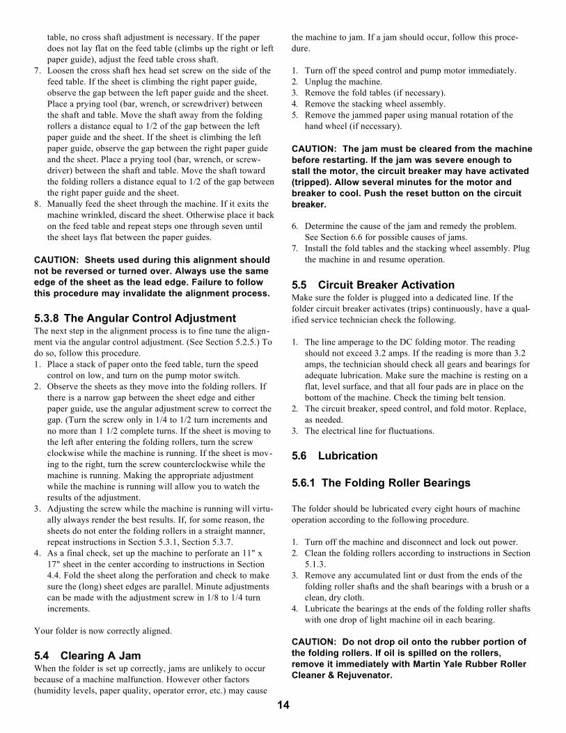
table, no cross shaft adjustment is necessary. If the paperdoes not lay flat on the feed table (climbs up the right or leftpaper guide), adjust the feed table cross shaft.
7. Loosen the cross shaft hex head set screw on the side of thefeed table. If the sheet is climbing the right paper guide,observe the gap between the left paper guide and the sheet.Place a prying tool (bar, wrench, or screwdriver) betweenthe shaft and table. Move the shaft away from the foldingrollers a distance equal to 1/2 of the gap between the leftpaper guide and the sheet. If the sheet is climbing the leftpaper guide, observe the gap between the right paper guideand the sheet. Place a prying tool (bar, wrench, or screw-driver) between the shaft and table. Move the shaft towardthe folding rollers a distance equal to 1/2 of the gap betweenthe right paper guide and the sheet.
8. Manually feed the sheet through the machine. If it exits themachine wrinkled, discard the sheet. Otherwise place it backon the feed table and repeat steps one through seven untilthe sheet lays flat between the paper guides.
CAUTION: Sheets used during this alignment shouldnot be reversed or turned over. Always use the sameedge of the sheet as the lead edge. Failure to followthis procedure may invalidate the alignment process.
5.3.8 The Angular Control AdjustmentThe next step in the alignment process is to fine tune the align-ment via the angular control adjustment. (See Section 5.2.5.) Todo so, follow this procedure.1. Place a stack of paper onto the feed table, turn the speed
control on low, and turn on the pump motor switch.2. Observe the sheets as they move into the folding rollers. If
there is a narrow gap between the sheet edge and eitherpaper guide, use the angular adjustment screw to correct thegap. (Turn the screw only in 1/4 to 1/2 turn increments andno more than 1 1/2 complete turns. If the sheet is moving tothe left after entering the folding rollers, turn the screwclockwise while the machine is running. If the sheet is mov-ing to the right, turn the screw counterclockwise while themachine is running. Making the appropriate adjustmentwhile the machine is running will allow you to watch theresults of the adjustment.
3. Adjusting the screw while the machine is running will virtu-ally always render the best results. If, for some reason, thesheets do not enter the folding rollers in a straight manner,repeat instructions in Section 5.3.1, Section 5.3.7.
4. As a final check, set up the machine to perforate an 11" x17" sheet in the center according to instructions in Section4.4. Fold the sheet along the perforation and check to makesure the (long) sheet edges are parallel. Minute adjustmentscan be made with the adjustment screw in 1/8 to 1/4 turnincrements.
Your folder is now correctly aligned.
5.4 Clearing A JamWhen the folder is set up correctly, jams are unlikely to occurbecause of a machine malfunction. However other factors(humidity levels, paper quality, operator error, etc.) may cause
the machine to jam. If a jam should occur, follow this proce-dure.
1. Turn off the speed control and pump motor immediately.2. Unplug the machine.3. Remove the fold tables (if necessary).4. Remove the stacking wheel assembly.5. Remove the jammed paper using manual rotation of the
hand wheel (if necessary).
CAUTION: The jam must be cleared from the machinebefore restarting. If the jam was severe enough tostall the motor, the circuit breaker may have activated(tripped). Allow several minutes for the motor andbreaker to cool. Push the reset button on the circuitbreaker.
6. Determine the cause of the jam and remedy the problem.See Section 6.6 for possible causes of jams.
7. Install the fold tables and the stacking wheel assembly. Plugthe machine in and resume operation.
5.5 Circuit Breaker ActivationMake sure the folder is plugged into a dedicated line. If thefolder circuit breaker activates (trips) continuously, have a qual-ified service technician check the following.
1. The line amperage to the DC folding motor. The readingshould not exceed 3.2 amps. If the reading is more than 3.2amps, the technician should check all gears and bearings foradequate lubrication. Make sure the machine is resting on aflat, level surface, and that all four pads are in place on thebottom of the machine. Check the timing belt tension.
2. The circuit breaker, speed control, and fold motor. Replace,as needed.
3. The electrical line for fluctuations.
5.6 Lubrication
5.6.1 The Folding Roller Bearings
The folder should be lubricated every eight hours of machineoperation according to the following procedure.
1. Turn off the machine and disconnect and lock out power. 2. Clean the folding rollers according to instructions in Section
5.1.3.3. Remove any accumulated lint or dust from the ends of the
folding roller shafts and the shaft bearings with a brush or aclean, dry cloth.
4. Lubricate the bearings at the ends of the folding roller shaftswith one drop of light machine oil in each bearing.
CAUTION: Do not drop oil onto the rubber portion ofthe folding rollers. If oil is spilled on the rollers,remove it immediately with Martin Yale Rubber RollerCleaner & Rejuvenator.
14
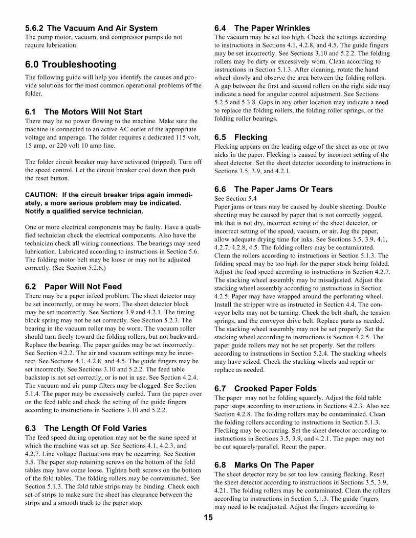
5.6.2 The Vacuum And Air SystemThe pump motor, vacuum, and compressor pumps do notrequire lubrication.
6.0 TroubleshootingThe following guide will help you identify the causes and pro-vide solutions for the most common operational problems of thefolder.
6.1 The Motors Will Not StartThere may be no power flowing to the machine. Make sure themachine is connected to an active AC outlet of the appropriatevoltage and amperage. The folder requires a dedicated 115 volt,15 amp, or 220 volt 10 amp line.
The folder circuit breaker may have activated (tripped). Turn offthe speed control. Let the circuit breaker cool down then pushthe reset button.
CAUTION: If the circuit breaker trips again immedi-ately, a more serious problem may be indicated.Notify a qualified service technician.
One or more electrical components may be faulty. Have a quali-fied technician check the electrical components. Also have thetechnician check all wiring connections. The bearings may needlubrication. Lubricated according to instructions in Section 5.6.The folding motor belt may be loose or may not be adjustedcorrectly. (See Section 5.2.6.)
6.2 Paper Will Not FeedThere may be a paper infeed problem. The sheet detector maybe set incorrectly, or may be worn. The sheet detector blockmay be set incorrectly. See Sections 3.9 and 4.2.1. The timingblock spring may not be set correctly. See Section 5.2.3. Thebearing in the vacuum roller may be worn. The vacuum rollershould turn freely toward the folding rollers, but not backward.Replace the bearing. The paper guides may be set incorrectly.See Section 4.2.2. The air and vacuum settings may be incor-rect. See Sections 4.1, 4.2.8, and 4.5. The guide fingers may beset incorrectly. See Sections 3.10 and 5.2.2. The feed tablebackstop is not set correctly, or is not in use. See Section 4.2.4.The vacuum and air pump filters may be clogged. See Section5.1.4. The paper may be excessively curled. Turn the paper overon the feed table and check the setting of the guide fingersaccording to instructions in Sections 3.10 and 5.2.2.
6.3 The Length Of Fold VariesThe feed speed during operation may not be the same speed atwhich the machine was set up. See Sections 4.1, 4.2.3, and4.2.7. Line voltage fluctuations may be occurring. See Section5.5. The paper stop retaining screws on the bottom of the foldtables may have come loose. Tighten both screws on the bottomof the fold tables. The folding rollers may be contaminated. SeeSection 5.1.3. The fold table strips may be binding. Check eachset of strips to make sure the sheet has clearance between thestrips and a smooth track to the paper stop.
6.4 The Paper WrinklesThe vacuum may be set too high. Check the settings accordingto instructions in Sections 4.1, 4.2.8, and 4.5. The guide fingersmay be set incorrectly. See Sections 3.10 and 5.2.2. The foldingrollers may be dirty or excessively worn. Clean according toinstructions in Section 5.1.3. After cleaning, rotate the handwheel slowly and observe the area between the folding rollers.A gap between the first and second rollers on the right side mayindicate a need for angular control adjustment. See Sections5.2.5 and 5.3.8. Gaps in any other location may indicate a needto replace the folding rollers, the folding roller springs, or thefolding roller bearings.
6.5 FleckingFlecking appears on the leading edge of the sheet as one or twonicks in the paper. Flecking is caused by incorrect setting of thesheet detector. Set the sheet detector according to instructions inSections 3.5, 3.9, and 4.2.1.
6.6 The Paper Jams Or Tears See Section 5.4Paper jams or tears may be caused by double sheeting. Doublesheeting may be caused by paper that is not correctly jogged,ink that is not dry, incorrect setting of the sheet detector, orincorrect setting of the speed, vacuum, or air. Jog the paper,allow adequate drying time for inks. See Sections 3.5, 3.9, 4.1,4.2.7, 4.2.8, 4.5. The folding rollers may be contaminated.Clean the rollers according to instructions in Section 5.1.3. Thefolding speed may be too high for the paper stock being folded.Adjust the feed speed according to instructions in Section 4.2.7.The stacking wheel assembly may be misadjusted. Adjust thestacking wheel assembly according to instructions in Section4.2.5. Paper may have wrapped around the perforating wheel.Install the stripper wire as instructed in Section 4.4. The con-veyor belts may not be turning. Check the belt shaft, the tensionsprings, and the conveyor drive belt. Replace parts as needed.The stacking wheel assembly may not be set properly. Set thestacking wheel according to instructions is Section 4.2.5. Thepaper guide rollers may not be set properly. Set the rollersaccording to instructions in Section 5.2.4. The stacking wheelsmay have seized. Check the stacking wheels and repair orreplace as needed.
6.7 Crooked Paper FoldsThe paper may not be folding squarely. Adjust the fold tablepaper stops according to instructions in Sections 4.2.3. Also seeSection 4.2.8. The folding rollers may be contaminated. Cleanthe folding rollers according to instructions in Section 5.1.3.Flecking may be occurring. Set the sheet detector according toinstructions in Sections 3.5, 3.9, and 4.2.1. The paper may notbe cut squarely/parallel. Recut the paper.
6.8 Marks On The PaperThe sheet detector may be set too low causing flecking. Resetthe sheet detector according to instructions in Sections 3.5, 3.9,4.21. The folding rollers may be contaminated. Clean the rollersaccording to instructions in Section 5.1.3. The guide fingersmay need to be readjusted. Adjust the fingers according to
15
instructions in Sections 3.10 and 5.2.2. The air and vacuum set-tings may be set incorrectly. Check the settings according toinstructions in Sections 4.1, 4.2.8, and 4.5. The ink on the fold-ed sheet may not be dry. Allow adequate drying time beforeattempting to fold. Remember - humidity will govern the lengthof drying time.
16
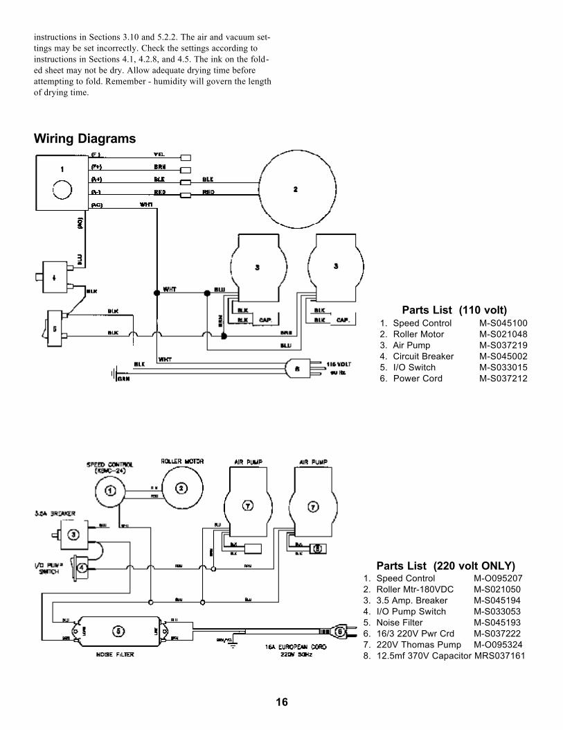
Wiring Diagrams
Parts List (110 volt)1. Speed Control M-S0451002. Roller Motor M-S0210483. Air Pump M-S0372194. Circuit Breaker M-S0450025. I/O Switch M-S0330156. Power Cord M-S037212
Parts List (220 volt ONLY)1. Speed Control M-O0952072. Roller Mtr-180VDC M-S0210503. 3.5 Amp. Breaker M-S0451944. I/O Pump Switch M-S0330535. Noise Filter M-S0451936. 16/3 220V Pwr Crd M-S0372227. 220V Thomas Pump M-O0953248. 12.5mf 370V Capacitor MRS037161

17
PARTS LIST
Item # Part No. Qty. Description1 M-O095015 1 Paper Guide Shaft2 W-O095238 1 R.H. Rod Clamp3 W-O095214 1 L.H. Rod Clamp4 W-O095215 2 Grip Plate5 M-S014016 1 4L1-FF Nyliner6 W-A095232 1 Back Stop7 M-S043036 5.59’ 1/2 ID Vinyl Hose
(RH Paper Guide)8 M-S043031 2 3/8 x 1/2 x 90 Hose Fitting9 M-S043036 3.17’ 1/2 ID Vinyl Hose
(LH Paper Guide)10 W-O095213 1 L.H. Paper Guide11 M-S015281 1 Air/Vacuum Control Label 12 W-O095212 1 R.H. Paper Guide13 W-O095307 1 Feed Table14 W-O095288 1 Front Panel15 M-S63251449 4 1/4 X 20 Keps Nut16 W-O095305 1 Base17 M-S63751408 4 Glide (Foot)18 M-S037219 2 Filter Element19 M-O095219 2 Air/Vacuum Pump, 110V20 M-S043051 2 3/8 NPT x 5/8 Hose Fitting21 W-O095298 1 Pump Vent Guard22 W-O095299 2 Pump Guard Bracket23 M-S63751547 3 Control Knob24 W-O095309 3 Control Valve25 M-S018002 3 1/8 x 3/4 Roll Pin26 M-S021048 1 100VDC Roller Drive Motor27 W-O095310 1 Air Vacuum Manifold28 W-O095304 1 L.H. Main Frame29 W-O095255 1 Feed Shaft30 M-S003048 1 10-32 x 1 1/2 SHC Screw31 M-O000160 1 Spacer32 M-S037304 1 Turnbuckle #8-3233 M-O095220 1 Air Timing Block34 W-O032036 1 1/4 - 20 x 5/8 Thumb Knob35 M-S013044 1 1/4 X 7/6 X 1 Bushing36 W-S013008 2 Machined Bushing37 M-S007018 1 1/4-20 DC Thumb Nut38 M-O095038 2 Shaft Collar39 M-S031073 1 Compression Spring40 M-S013045 2 .628 x 1 x 1/8 Bushing41 M-S008008 1 1/4 I.D x 1/2 O.D. Flat Washer42 W-A095224 1 Sheet Detector Assembly43 W-O095279 1 Roller Guard44 M-O095221 2 Guide Finger Collar45 W-O095233 2 Guide Finger46 W-O003019 2 Accessory Journal47 M-O003083 2 Scoring Roller48 W-A03085B 1 7 Tooth Perforator49 M-O003080 2 Rubber Guide Roller50 M-O003082 2 Lower Back Up Hub51 M-O003076 2 Guide Roller Back Up Hub52 M-O003066 1 Tie Rod53 M-O095905 1 Left Cover54 W-O095136 1 Dual Gear55 M-S013009 1 3/8 ID Bushing w/Flats56 W-O095295 1 Rear Cover Mount Bracket (LH)57 W-O095275 1 Bearing Plate58 W-O095265 1 Roller Guard Bracket (RH)
Item # Part No. Qty. Description59 M-S037347 1 Vacuum Gauge, 1/8 NPT60 M-S013010 3 3/8 ID Flanged Bushing61 W-O095294 1 Side Cover Mount Bracket (LH)62 W-S022019 1 44T Timing Pulley w/Flange63 M-S025010 2 210 XL037 Timing Belt64 M-S022021 2 60/15T Timing Pulley65 M-S025008 1 144 XL037 Timing Belt66 M-O095903 1 14T, 3/8” ID Nylon Gear67 M-S013053 1 1/2 X 5/8 X 1 Bushing68 M-O095242 1 Tapered Index Pin69 M-S035007 1 3/8 ID Rubber Grommet70 M-S045194 1 Circuit Breaker71 W-A095300 1 R.H. Side Frame72 W-O095303 1 Side Cover Mount Bracket (RH)73 WRA420028 1 4200 Speed Control Assy74 M-S022017 1 12T Motor Pulley75 W-O095302 1 Rear Cover Mount Bracket (RH)76 M-O003033 2 24T x 3/8ID Nylon Gear77 M-S033015 1 110VAC Rocker Switch, 1HP78 M-S033053 1 220VAC Rocker Switch79 M-S032057 1 Speed Control Knob80 M-S015024 1 Speed Control Plate81 M-S015267 2 Side Cover Label82 M-S032047 1 Hand Wheel83 M-O095904 1 Right Cover84 W-O001560 1 Belt Guard85 W-O095289 1 Rear Panel86 M-O003035 2 18T x 3/8ID Nylon Gear87 M-O003036 2 18T x 1/4ID Nylon Gear88 M-O03034A 1 24T x 1/2ID Nylon Gear89 M-O003074 1 Idler Gear Stud90 M-O095320 1 Idler Stud, 95991 M-S013013 1 Thick Flanged Bushing92 M-S031059 4 Folding Roller Spring93 W-O095280 1 Roller Guard Bracket (LH)94 M-O095230 2 Rubber Ring, Vacuum Roller95 M-O095216 1 Vacuum Roller96 M-S020009 2 Clutch Bearing97 W-O095276 2 Tie Rod98 M-O003104 11 Feed Table Pins99 W-O095014 1 Roller Adjust Channel
100 M-O095222 1 Nose Pipe101 W-A095223 1 Retarder Block Assembly102 W-O095027 1 Adjustable Spring Stop103 M-A003018 2 Accessory Shaft104 WRA003015 3 Folding Roller105 WRA095034 1 Main Drive Roller106 W-O095135 1 Conveyor Drive Shaft107 W-O095035 1 Exit Table108 M-S031034 4 Compression Spring109 W-S014005 2 Nylon Bearing110 W-O008017 1 Square Shaft111 W-O008012 1 Paper Deflector112 M-S031050 1 Compression Spring113 M-S034001 4 Stacking Wheel114 W-O003093 1 Stacking Wheel Shaft115 W-O095268 2 Stacking Wheel Weight116 W-O008013 1 Stacking Finger Spring117 W-O003090 1 Axle Housing118 M-S043046 1 Vinyl Tip

18
Parts Diagram #1
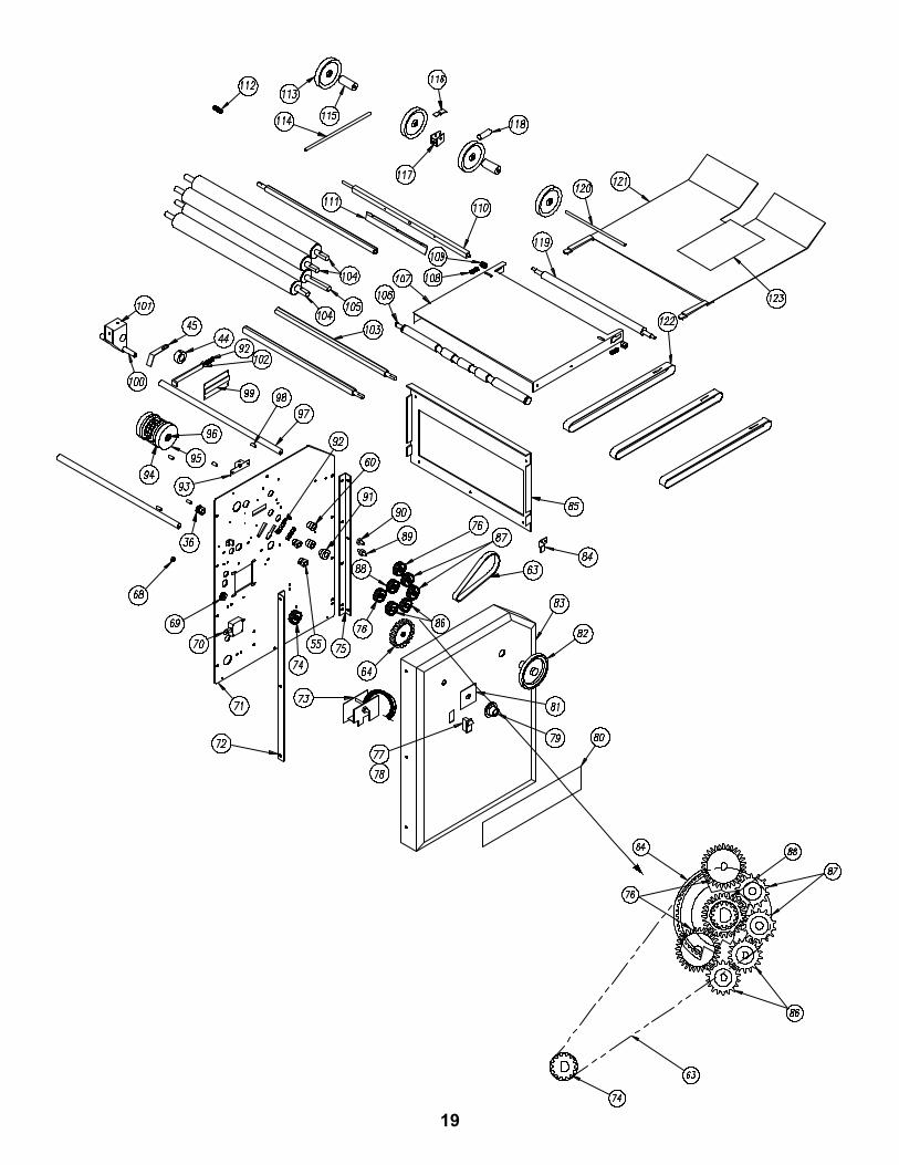
19
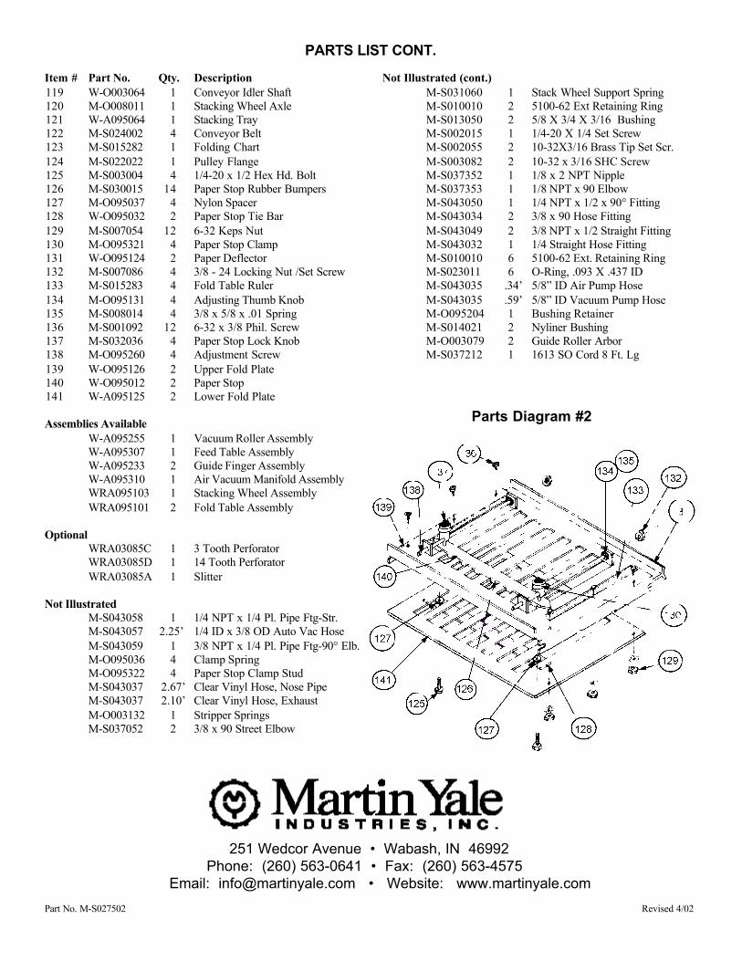
Item # Part No. Qty. Description119 W-O003064 1 Conveyor Idler Shaft120 M-O008011 1 Stacking Wheel Axle121 W-A095064 1 Stacking Tray122 M-S024002 4 Conveyor Belt123 M-S015282 1 Folding Chart124 M-S022022 1 Pulley Flange125 M-S003004 4 1/4-20 x 1/2 Hex Hd. Bolt126 M-S030015 14 Paper Stop Rubber Bumpers127 M-O095037 4 Nylon Spacer128 W-O095032 2 Paper Stop Tie Bar129 M-S007054 12 6-32 Keps Nut130 M-O095321 4 Paper Stop Clamp131 W-O095124 2 Paper Deflector132 M-S007086 4 3/8 - 24 Locking Nut /Set Screw133 M-S015283 4 Fold Table Ruler134 M-O095131 4 Adjusting Thumb Knob135 M-S008014 4 3/8 x 5/8 x .01 Spring136 M-S001092 12 6-32 x 3/8 Phil. Screw137 M-S032036 4 Paper Stop Lock Knob138 M-O095260 4 Adjustment Screw139 W-O095126 2 Upper Fold Plate140 W-O095012 2 Paper Stop141 W-A095125 2 Lower Fold Plate
Assemblies AvailableW-A095255 1 Vacuum Roller AssemblyW-A095307 1 Feed Table AssemblyW-A095233 2 Guide Finger AssemblyW-A095310 1 Air Vacuum Manifold AssemblyWRA095103 1 Stacking Wheel AssemblyWRA095101 2 Fold Table Assembly
OptionalWRA03085C 1 3 Tooth Perforator WRA03085D 1 14 Tooth Perforator WRA03085A 1 Slitter
Not IllustratedM-S043058 1 1/4 NPT x 1/4 Pl. Pipe Ftg-Str.M-S043057 2.25’ 1/4 ID x 3/8 OD Auto Vac HoseM-S043059 1 3/8 NPT x 1/4 Pl. Pipe Ftg-90° Elb.M-O095036 4 Clamp SpringM-O095322 4 Paper Stop Clamp StudM-S043037 2.67’ Clear Vinyl Hose, Nose PipeM-S043037 2.10’ Clear Vinyl Hose, ExhaustM-O003132 1 Stripper SpringsM-S037052 2 3/8 x 90 Street Elbow
Not Illustrated (cont.)M-S031060 1 Stack Wheel Support SpringM-S010010 2 5100-62 Ext Retaining RingM-S013050 2 5/8 X 3/4 X 3/16 BushingM-S002015 1 1/4-20 X 1/4 Set ScrewM-S002055 2 10-32X3/16 Brass Tip Set Scr.M-S003082 2 10-32 x 3/16 SHC ScrewM-S037352 1 1/8 x 2 NPT NippleM-S037353 1 1/8 NPT x 90 ElbowM-S043050 1 1/4 NPT x 1/2 x 90° FittingM-S043034 2 3/8 x 90 Hose FittingM-S043049 2 3/8 NPT x 1/2 Straight FittingM-S043032 1 1/4 Straight Hose FittingM-S010010 6 5100-62 Ext. Retaining RingM-S023011 6 O-Ring, .093 X .437 IDM-S043035 .34’ 5/8” ID Air Pump HoseM-S043035 .59’ 5/8” ID Vacuum Pump HoseM-O095204 1 Bushing RetainerM-S014021 2 Nyliner BushingM-O003079 2 Guide Roller ArborM-S037212 1 1613 SO Cord 8 Ft. Lg
PARTS LIST CONT.
Parts Diagram #2
251 Wedcor Avenue • Wabash, IN 46992Phone: (260) 563-0641 • Fax: (260) 563-4575
Email: [email protected] • Website: www.martinyale.com
Part No. M-S027502 Revised 4/02


![Untitled-8 [] · LAR Feed Cart FEED CARTS Lab Animal Feed (I-AR) Carts — 52.05 LAR Feed Carts are designed to store and transport animal feed. Stainless steel finish](https://img.pdfslide.net/doc/110x75/5f535ab38fc1d822427a2182/untitled-8-lar-feed-cart-feed-carts-lab-animal-feed-i-ar-carts-a-5205-lar.jpg)