Embed Size (px)
Citation preview
Eurographics Workshop on Visual Computing for Biology and Medicine (2010)Dirk Bartz, Charl Botha, Joachim Hornegger and Raghu Machiraju (Editors)
Model-based Solid Texture Synthesisfor Anatomic Volume Illustration
Ilknur Kabul1, Derek Merck1, Julian Rosenman 1,2 and Stephen M. Pizer1
1 Department of Computer Science, UNC Chapel Hill, USA 2 Department of Radiation Oncology, UNC Chapel Hill, USA
AbstractMedical illustrations can make powerful use of texture synthesis to convey information about anatomic structuresin an attractive, effective and understandable way. Current visualization methods are not capable of conveyingdetailed information about the orientation, internal structure, and other local properties of the anatomical objectsfor a particular patient because imaging modalities such as CT or MRI do not capture this information. In this pa-per, a new anatomical rendering method that utilizes model-based synthesis of 3D textures is proposed in order todistinguish and illustrate different structures inside the model. The goal of our volume illustration approach is tovisualize structural information by considering directions and layers in synthesizing high-quality, high-resolutionsolid textures. Our method uses medial coordinates of 3D models and 2D exemplar textures to generate solidtextures that change progressively in orientation and material according to the local orientation and transitioninformation implicit in the anatomic region.Discrete medial 3D anatomical models ("m-reps") provide the orien-tation field and texture variation maps inside image regions. In our paper, we demonstrate the robustness of ourmethod with a variety of textures applied to different anatomical structures, such as muscles, and mandible.
1. Introduction
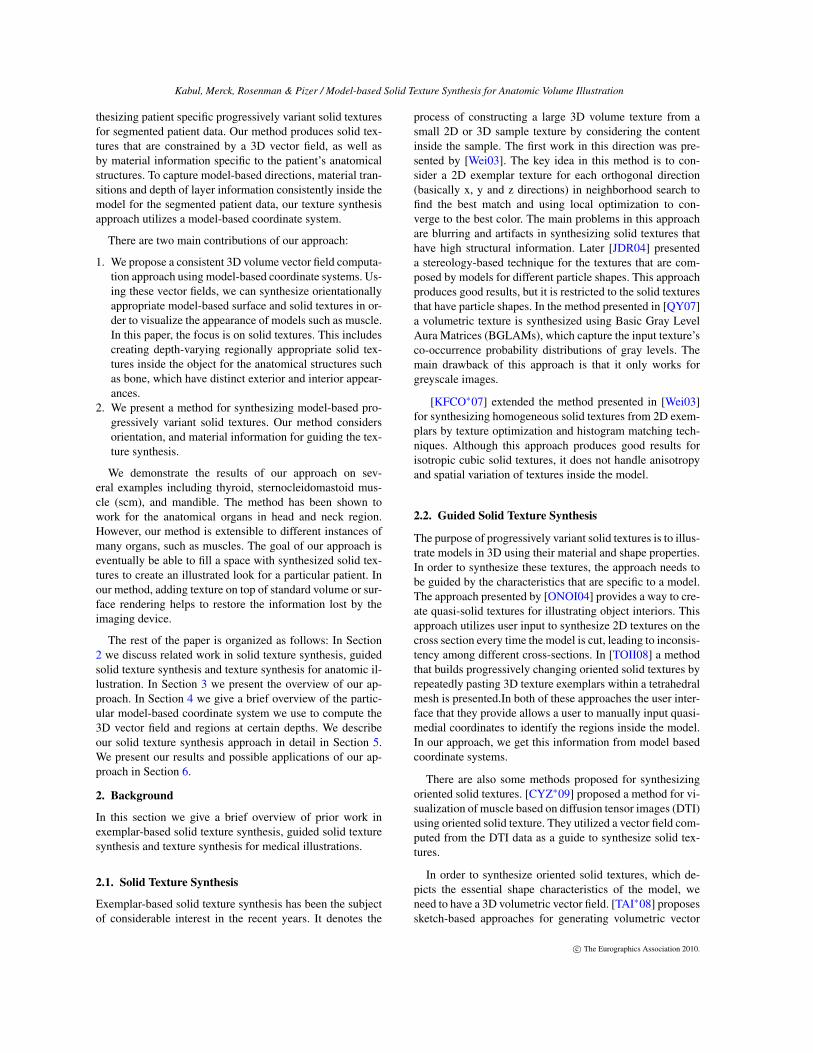
The main goal of medical visualization is to create under-standing of the information present in the given data. Suchillustrations play a major role in many different areas suchas medical education, surgical training, and procedure plan-ning. Textbook illustrations of different anatomical struc-tures are commonly used in medical education. These illus-trations are effective in explaining the structural properties(e.g., shape, size, appearance, etc.) of the organs and thespatial relations between them. Many of these illustrationsuse textures both as a means to distinguish structures fromone another by appearance, as well as to convey local struc-tural detail such as orientation and scale. For example, Fig. 1shows an illustration of head and neck region and a corre-sponding computed tomography (CT) image obtained usingvolume rendering. In this figure, the textures help to visual-ize details of the organs.
Many anatomical objects have slowly changing varia-tions in local material properties, such as material type,scale and orientation, over the surface of the model and in-side the model. In hand-drawn medical illustrations com-monly used for anatomy reference, many anatomical struc-
Figure 1: A scientific illustration [Net09] shows more gen-eral information than the correspondingtures are shown with appearances that suggest features ar-ranged along, across and around the object, and inside theobject. For example, the layered muscle linings of the duo-denum and the stomach have respective directional compo-nents along and around the object. In addition, the represen-tation of the layers inside the object should be consideredin the visualization of anatomical organs. For example, bonehas hard exterior, soft interior, and soft marrow interior re-gions.
In order to provide this behavior (such as the ones in med-ical textbooks) for the illustrative visualization of patientdata sets in a 3D environment, we present a method for syn-
c© The Eurographics Association 2010.
Kabul, Merck, Rosenman & Pizer / Model-based Solid Texture Synthesis for Anatomic Volume Illustration
thesizing patient specific progressively variant solid texturesfor segmented patient data. Our method produces solid tex-tures that are constrained by a 3D vector field, as well asby material information specific to the patient’s anatomicalstructures. To capture model-based directions, material tran-sitions and depth of layer information consistently inside themodel for the segmented patient data, our texture synthesisapproach utilizes a model-based coordinate system.
There are two main contributions of our approach:
1. We propose a consistent 3D volume vector field computa-tion approach using model-based coordinate systems. Us-ing these vector fields, we can synthesize orientationallyappropriate model-based surface and solid textures in or-der to visualize the appearance of models such as muscle.In this paper, the focus is on solid textures. This includescreating depth-varying regionally appropriate solid tex-tures inside the object for the anatomical structures suchas bone, which have distinct exterior and interior appear-ances.
2. We present a method for synthesizing model-based pro-gressively variant solid textures. Our method considersorientation, and material information for guiding the tex-ture synthesis.
We demonstrate the results of our approach on sev-eral examples including thyroid, sternocleidomastoid mus-cle (scm), and mandible. The method has been shown towork for the anatomical organs in head and neck region.However, our method is extensible to different instances ofmany organs, such as muscles. The goal of our approach iseventually be able to fill a space with synthesized solid tex-tures to create an illustrated look for a particular patient. Inour method, adding texture on top of standard volume or sur-face rendering helps to restore the information lost by theimaging device.
The rest of the paper is organized as follows: In Section2 we discuss related work in solid texture synthesis, guidedsolid texture synthesis and texture synthesis for anatomic il-lustration. In Section 3 we present the overview of our ap-proach. In Section 4 we give a brief overview of the partic-ular model-based coordinate system we use to compute the3D vector field and regions at certain depths. We describeour solid texture synthesis approach in detail in Section 5.We present our results and possible applications of our ap-proach in Section 6.
2. Background
In this section we give a brief overview of prior work inexemplar-based solid texture synthesis, guided solid texturesynthesis and texture synthesis for medical illustrations.
2.1. Solid Texture Synthesis
Exemplar-based solid texture synthesis has been the subjectof considerable interest in the recent years. It denotes the
process of constructing a large 3D volume texture from asmall 2D or 3D sample texture by considering the contentinside the sample. The first work in this direction was pre-sented by [Wei03]. The key idea in this method is to con-sider a 2D exemplar texture for each orthogonal direction(basically x, y and z directions) in neighborhood search tofind the best match and using local optimization to con-verge to the best color. The main problems in this approachare blurring and artifacts in synthesizing solid textures thathave high structural information. Later [JDR04] presenteda stereology-based technique for the textures that are com-posed by models for different particle shapes. This approachproduces good results, but it is restricted to the solid texturesthat have particle shapes. In the method presented in [QY07]a volumetric texture is synthesized using Basic Gray LevelAura Matrices (BGLAMs), which capture the input texture’sco-occurrence probability distributions of gray levels. Themain drawback of this approach is that it only works forgreyscale images.
[KFCO∗07] extended the method presented in [Wei03]for synthesizing homogeneous solid textures from 2D exem-plars by texture optimization and histogram matching tech-niques. Although this approach produces good results forisotropic cubic solid textures, it does not handle anisotropyand spatial variation of textures inside the model.
2.2. Guided Solid Texture Synthesis
The purpose of progressively variant solid textures is to illus-trate models in 3D using their material and shape properties.In order to synthesize these textures, the approach needs tobe guided by the characteristics that are specific to a model.The approach presented by [ONOI04] provides a way to cre-ate quasi-solid textures for illustrating object interiors. Thisapproach utilizes user input to synthesize 2D textures on thecross section every time the model is cut, leading to inconsis-tency among different cross-sections. In [TOII08] a methodthat builds progressively changing oriented solid textures byrepeatedly pasting 3D texture exemplars within a tetrahedralmesh is presented.In both of these approaches the user inter-face that they provide allows a user to manually input quasi-medial coordinates to identify the regions inside the model.In our approach, we get this information from model basedcoordinate systems.
There are also some methods proposed for synthesizingoriented solid textures. [CYZ∗09] proposed a method for vi-sualization of muscle based on diffusion tensor images (DTI)using oriented solid texture. They utilized a vector field com-puted from the DTI data as a guide to synthesize solid tex-tures.
In order to synthesize oriented solid textures, which de-picts the essential shape characteristics of the model, weneed to have a 3D volumetric vector field. [TAI∗08] proposessketch-based approaches for generating volumetric vector
c© The Eurographics Association 2010.
Kabul, Merck, Rosenman & Pizer / Model-based Solid Texture Synthesis for Anatomic Volume Illustration
field. In this approach, the user specifies the strokes and thelayers by utilizing a user interface, which makes this methodunsuitable for our target problem of patient-specific synthe-sis. Therefore, our paper includes a method for computingsuch 3D vector fields and layers automatically.
2.3. Solid Texture Synthesis for Medical Visualization
Volume illustrations became popular over the past decadefor its effectiveness in illustrating the material and structuralfeatures of a data set while emphasizing important details.One approach is to generate volumetric illustrations by syn-thesizing volume data with model-specific textures and dif-ferent rendering techniques. [DC05] proposed a method forsynthesizing oriented volumetric solid textures via a patch-based solid texture synthesis algorithm that uses the orienta-tion field extracted from the CT and user-provided 3D exem-plar textures. Later, [LE05] proposed a method to generateillustrative 3D textures using Wang Cubes. The main disad-vantages of this method are that the textures are not region-appropriate but rather are homogeneous throughout the vol-ume, nor do they reflect scale and orientation information.In addition, obtaining 3D texture samples is not easy to cap-ture, and tiling of the 3D textures leads to repetitive patterns.
3. Overview of Our Method
Our method synthesizes progressively changing solid tex-tures specific to a model of an anatomical object by consid-ering the orientation and variation of the textures inside themodel. The purpose of our method is to obtain illustrativerenderings of patient-specific anatomical structures. The in-put to our system consists of a 3D triangular mesh model, amodel-based coordinate system for the model (in our methodobtained from a medial model of the object), and a prede-termined set of 2D exemplar textures. The output is a solidtextured model. Thus, our model-guided texture synthesis isa post-segmentation process.
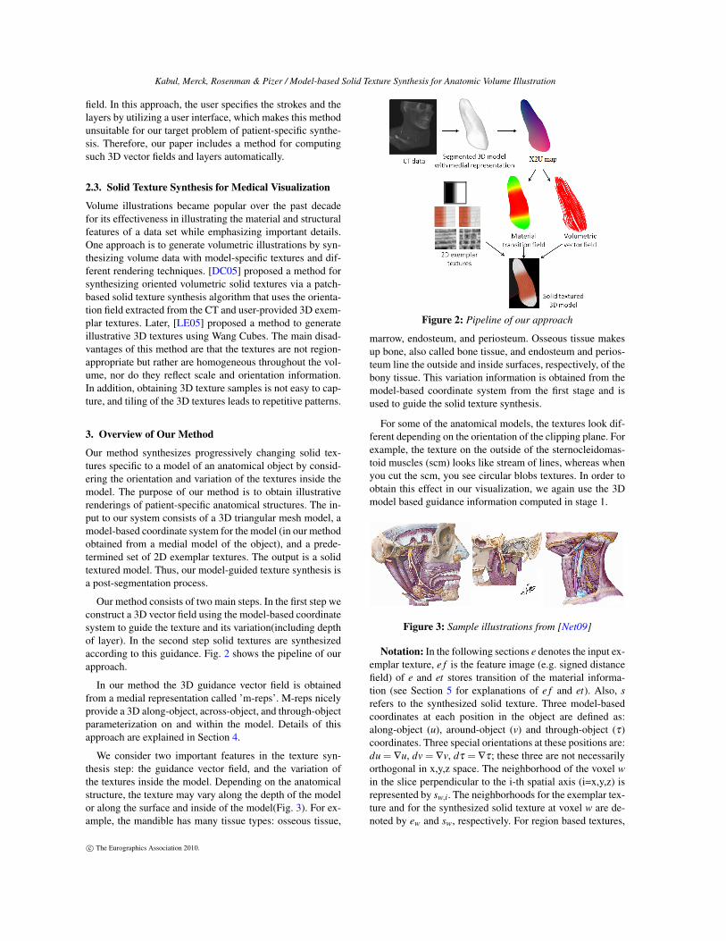
Our method consists of two main steps. In the first step weconstruct a 3D vector field using the model-based coordinatesystem to guide the texture and its variation(including depthof layer). In the second step solid textures are synthesizedaccording to this guidance. Fig. 2 shows the pipeline of ourapproach.
In our method the 3D guidance vector field is obtainedfrom a medial representation called ’m-reps’. M-reps nicelyprovide a 3D along-object, across-object, and through-objectparameterization on and within the model. Details of thisapproach are explained in Section 4.
We consider two important features in the texture syn-thesis step: the guidance vector field, and the variation ofthe textures inside the model. Depending on the anatomicalstructure, the texture may vary along the depth of the modelor along the surface and inside of the model(Fig. 3). For ex-ample, the mandible has many tissue types: osseous tissue,
Figure 2: Pipeline of our approach
marrow, endosteum, and periosteum. Osseous tissue makesup bone, also called bone tissue, and endosteum and perios-teum line the outside and inside surfaces, respectively, of thebony tissue. This variation information is obtained from themodel-based coordinate system from the first stage and isused to guide the solid texture synthesis.
For some of the anatomical models, the textures look dif-ferent depending on the orientation of the clipping plane. Forexample, the texture on the outside of the sternocleidomas-toid muscles (scm) looks like stream of lines, whereas whenyou cut the scm, you see circular blobs textures. In order toobtain this effect in our visualization, we again use the 3Dmodel based guidance information computed in stage 1.
Figure 3: Sample illustrations from [Net09]
Notation: In the following sections e denotes the input ex-emplar texture, e f is the feature image (e.g. signed distancefield) of e and et stores transition of the material informa-tion (see Section 5 for explanations of e f and et). Also, srefers to the synthesized solid texture. Three model-basedcoordinates at each position in the object are defined as:along-object (u), around-object (v) and through-object (τ)coordinates. Three special orientations at these positions are:du = ∇u, dv = ∇v, dτ = ∇τ; these three are not necessarilyorthogonal in x,y,z space. The neighborhood of the voxel win the slice perpendicular to the i-th spatial axis (i=x,y,z) isrepresented by sw,i. The neighborhoods for the exemplar tex-ture and for the synthesized solid texture at voxel w are de-noted by ew and sw, respectively. For region based textures,
c© The Eurographics Association 2010.
Kabul, Merck, Rosenman & Pizer / Model-based Solid Texture Synthesis for Anatomic Volume Illustration
st denotes the 3D transition field inside the model, which iscomputed using model parameterization.
4. Model-based Coordinate System
The problem of guided solid texture synthesis for anatom-ical structures is where to get the guidance. As discussedearlier, many textures on or within anatomical organs areoriented along or across the model, and they vary progres-sively depending on their position with respect to model.Thus, we propose a method for computing the along-object(u), around-object (v) and through-object (τ) coordinates forany point in world space within each region inside the modelin the scene (Fig. 4). These coordinates should provide cor-respondence between different instances of the anatomicalmodels. That is, corresponding points in different instancesof an anatomic object, such as an anatomical structure in dif-ferent patients, should have the same u,v,τ values.
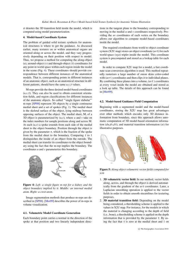
M-reps provide the three desired model-based coordinates(u,v,τ). They can also be used to obtain consistent orienta-tion fields, and region classifications for different instancesof the anatomic objects. So called "’single figure slabular"’m-reps [SP08] represent 3D objects by a single continuousmedial sheet and a set of spokes (Fig. 1). The medial sheetis the skeletal surface of the object, lying midway betweenopposing surfaces of the object. The medial sheet, M, of a3D object is parameterized by (u,v), where u and v take onthe index numbers for sample positions along and across M.At each (u,v) a spoke extends from each side of the medialsheet to the object boundary. Position through the object isgiven by the parameter τ , which is the fraction of the spokefrom the medial sheet to the boundary. Comparing τ to 1distinguishes the inside of an object from the outside. Themedial sheet can transfer its coordinates to the object bound-ary using the fact that the m-rep implies the boundary. Thecoordinates u and v parameterize this boundary.
Figure 4: Left: a single figure m-rep for a kidney and theobject boundary implied by it. Middle: an internal medialatom. Right: a crest atom.
Image segmentation methods that produce m-reps are de-scribed in [SP08]. [Mer09] describes the power of m-reps involume visualization.
4.1. Volumetric Model Coordinate Generation
Each boundary point carries a normal in the direction of thespoke at that position and two linearly independent direc-
tions in the tangent plane to the boundary corresponding tomoving in the medial u and v coordinates respectively. Pro-viding the uv coordinates of each vertex on the boundaryallows our algorithm to compute model-based coordinatesinside the model.
The required coordinates from world to object coordinatesystem (X2U map) stores an object coordinate (uvτ) for eachworld-space (xyz) triplet inside the model. This coordinatesystem is precomputed and stored as a lookup table for eachmodel.
In order to compute X2U map for a model, a fast coordi-nate scan-conversion algorithm is used. This method repeat-edly rasterizes a large number of onion skins color-codedwith (uvτ ) coordinates and then clips it to individual planes.By combining these planes into a volume, (uvτ ) coordinatesat every voxel inside the model are obtained and stored asa look up table. The details of this approach can be foundin [Mer09].
4.2. Model-based Guidance Field Computation
Beginning with a segmented model and the model-basedcoordinates, storing the X2U map has great advantagesover other methods which encodes only 3D distance in-formation from boundary, since this approach allows auto-matic computation of 3D model-based orientation informa-tion (du,dv,dτ), and material transition information (st) forillustrative purposes.
Figure 5: Along object volumetric vector fields computed forscm
1. 3D volumetric vector field: In our method, vector fieldsalong, across, and through the object is derived automat-ically from the gradient of the uvτ coordinates. Later, aLaplacian smoothing operation is applied to the vectorfields in order to obtain smooth streamlines for texturingpurposes.
2. 3D material transition field: Depending on the modelbeing considered, a thresholding scheme is applied to thevalues in X2U map. For instance, for the models in whichthe material is changing according to the depth of field(i.e., bone), a thresholding scheme is applied on the depthinformation that is provided by the parameter τ . By us-ing the fact that τ is zero at the medial sheet and 1 on
c© The Eurographics Association 2010.
Kabul, Merck, Rosenman & Pizer / Model-based Solid Texture Synthesis for Anatomic Volume Illustration
the boundary, the regions are classified by setting thresh-old values for τ (e.g., 0 < τ < 0.5 is the marrow region,0.5<τ<0.7 is the interior bone region, and 0.7 < τ< 1 isthe exterior bone region). After regions are classified, thisinformation is used to compute a smooth transition field,st, for each voxel inside the model.
5. Solid Texture Synthesis
Given a surface model with its medial representation and2D exemplar textures, our method first computes the modelbased vector fields and region masks, and then it uses themto synthesize model-based progressively changing solid tex-tures inside the models. The 2D input exemplar textures suit-able for synthesizing anatomic structures are taken from il-lustrated sources such as [Net09] or from specifically de-signed anatomic texture catalogs.
Our solid texture synthesis method is based on thebasic non-parametric exemplar-based techniques used in[KFCO∗07], in which uniform cubic solid textures are syn-thesized from 2D exemplar textures. The major contribu-tion of our method is providing an extension to this methodto efficiently support object-specific progressively changingtextures. In addition, we add model-based texture synthesiscontrol to restrict the appearance of the textures for clip-ping planes that are rotated based on the orientation of me-dial axis. As opposed to the approach presented in [TOII08],control of texture variation and texture orientation is accom-plished by generating the textures "in-place" for a model inworld space instead of in model space. This approach pre-vents the possible seams that might be caused by bendingand twisting a standard texture cube according to a particu-lar model.
5.1. Iterative Solid Texture Synthesis
The approach presented in [KFCO∗07] is a two phase op-timization method that tries to minimize the sum of differ-ences under the Lp norm between each local neighborhoodsw,i (i=x,y,z) of a voxel w in the output texture and a corre-sponding neighborhood ew,i (i=x,y,z) in the 2D example tex-ture e. Initially the colors are randomly generated for eachvoxel inside the cube from the 2D examplar textures. Thenin the first stage the matching neighborhood of each voxel isdetermined by optimizing the energy function Et :
Et(s;{e}) = ∑w
∑i∈x,y,z
||sw,i− ew,i||r (1)
In the second stage the best matching neighborhood fromthe exemplar texture is searched for each voxel. The detailsof this approach can be found in [KFCO∗07].
5.2. Vector Guided Solid Texture Synthesis
In order to synthesize solid textures that are oriented alongthe model based vector field, we extend the neighborhood
search phase of the synthesis algorithm. In this phase of theapproach, the orthogonal neighborhoods sw,i (i=x,y,z) are ro-tated in 3D space around their center by a rotation matrix Rw,which is computed by considering the vectors duw, dvw, anddτw at that voxel w.
Rw =
duxw dvx
w dτxw
duyw dvy
w dτyw
duzw dvz
w dτzw
srw,i = Rw ∗ sw,i
Here, the rotated neighborhoods are denoted by srw,i(i=x,y,z). In our case, the pixels in srw,i (i=x,y,z) are resam-pled from that of synthesized texture s.
Algorithm 1 Guided Solid Texture Synthesis
e0w← random neighborhood in e
et0w← random neighborhood in et
Rw←Compute rotation matrix using duw,dvw and dτw
for n = 0 to N dosn+1
w ← arg min Et(sw;enw)
for i = (x,y,z) dosrn+1
w,i ← Rotate sw,i using Rw
strn+1w,i ← Rotate stw,i using Rw
en+1w,i ← Find nearest neighbor of srn+1
w,i in ei
which satisfies ||etn+1w,i − strn+1
w,i ||< thresholdend forif en+1
w = enw then
sw← sn+1w break
end ifend for
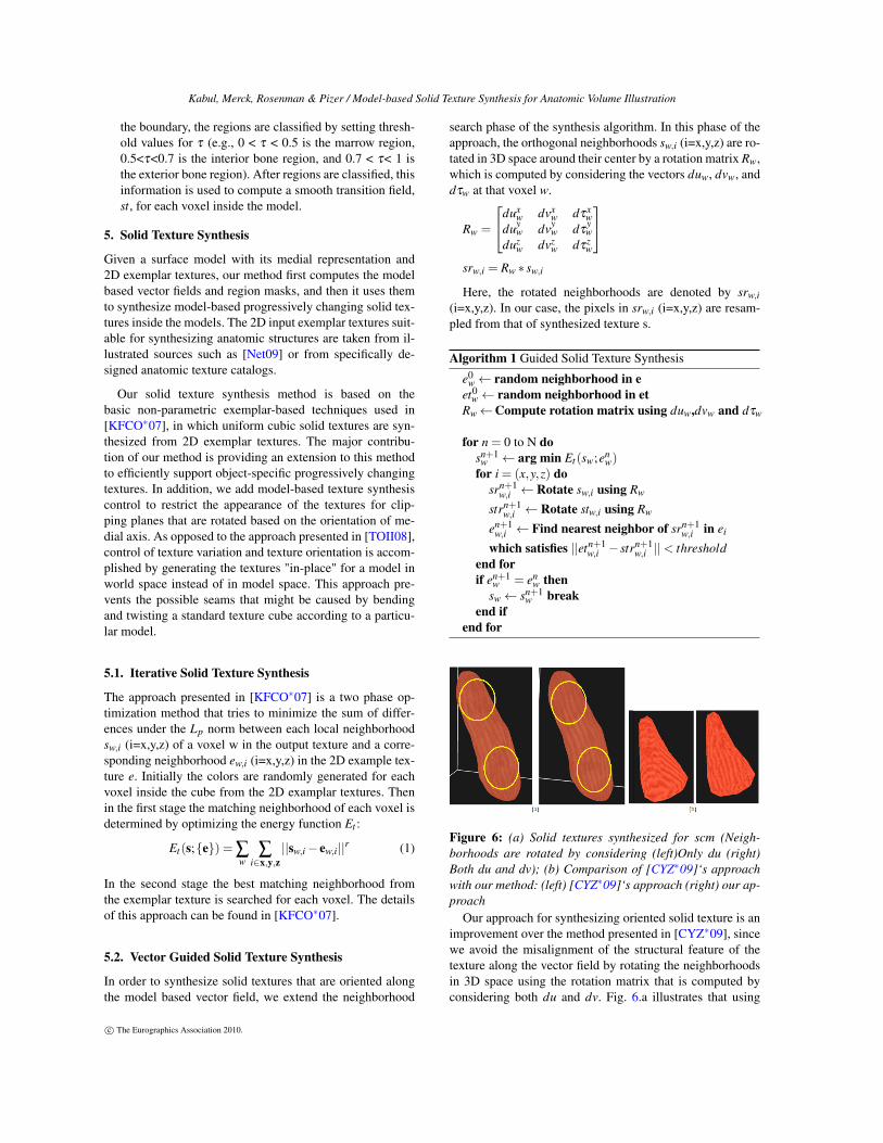
Figure 6: (a) Solid textures synthesized for scm (Neigh-borhoods are rotated by considering (left)Only du (right)Both du and dv); (b) Comparison of [CYZ∗09]‘s approachwith our method: (left) [CYZ∗09]‘s approach (right) our ap-proach
Our approach for synthesizing oriented solid texture is animprovement over the method presented in [CYZ∗09], sincewe avoid the misalignment of the structural feature of thetexture along the vector field by rotating the neighborhoodsin 3D space using the rotation matrix that is computed byconsidering both du and dv. Fig. 6.a illustrates that using
c© The Eurographics Association 2010.
Kabul, Merck, Rosenman & Pizer / Model-based Solid Texture Synthesis for Anatomic Volume Illustration
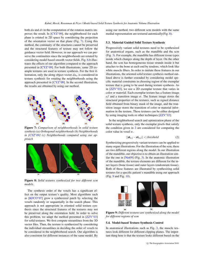
both du and dv in the computation of the rotation matrix im-proves the result. In [CYZ∗09], the neighborhood for eachplane is rotated in 2D space by considering the projectionof the orientation vector on that plane (Fig. 7). Using thismethod, the continuity of the structures cannot be preservedand the structural features of texture may not follow theguidance vector field. However, in our approach we can pre-serve the continuities since the neighborhoods are rotated byconsidering model based smooth vector fields. Fig. 6.b illus-trates the effects of our algorithm compared to the approachpresented in [CYZ∗09]. For both illustrations, same 2D ex-ample textures are used in texture synthesis. For the first il-lustration, only the along object vector duw is considered intexture synthesis for rotating the neighborhoods using theapproach presented in [CYZ∗09]. In the second illustration,the results are obtained by using our method.
Figure 7: Comparison of neighboorhoods in solid texturesynthesis (a) Orthogonal neighborhoods (b) Neighborhoodsin [CYZ∗09] (c) Neighborhoods computed using our ap-proach
Figure 8: Solid textures synthesized for two different scmmodels.
The synthesis order of the voxels has a significant ef-fect on the output texture‘s quality. Most algorithms suchas [KFCO∗07] grow a synthesized patch by selecting thevoxels randomly or sequantially in the search phase. Thisapproach is not appropriate in oriented solid texture syn-thesis since the structural features of the textures may notbe preserved along the orientation field. In order to solvethis problem, we adapt the method presented in [ZZV∗03]for solid textures. We first compute streamlines from the 3Dvector files. Then, the texture is synthesized by consideringthe individual streamlines in deciding the order of voxels tobe considered in the neighborhood search. Our algorithm isalso consistent for different instances of the same model. By
using our method, two different scm models with the samemedial representation are textured automically(Fig. 8).
5.3. Material Guided Solid Texture Synthesis
Progressively variant solid textures need to be synthesizedfor anatomical organs, such as the mandible and the scm(Fig. 3). For example, the mandible has different tissue typesinside which changes along the depth of layer. On the otherhand, the scm has homogeneous tissue strands inside it butattaches to the bone at each end by tendons, which look likewhite muscle fibers. In order to imitate these features in ourillustrations, the oriented solid texture synthesis method out-lined above is further extended by considering model spe-cific material constraints in choosing region of the exemplartexture that is going to be used during texture synthesis. Asin [ZZV∗03], we use a 2D exemplar texture that varies incolor or material. Each exemplar texture has a feature imagee f and a transition image et. The feature image stores thestructural properties of the textures, such as signed distancefield obtained from binary mask of the image, and the tran-sition image stores the transition of color or material infor-mation in the texture. These textures can be either designedby using imaging tools or other techniques [ZZV∗03].
In the neighborhood search and optimization phase of thesolid texture synthesis, only the exemplar pixels that satisfythe condition given in 2 are considered for computing thecolor value in voxel w.
||stw,i− etw,i||< threshold (2)
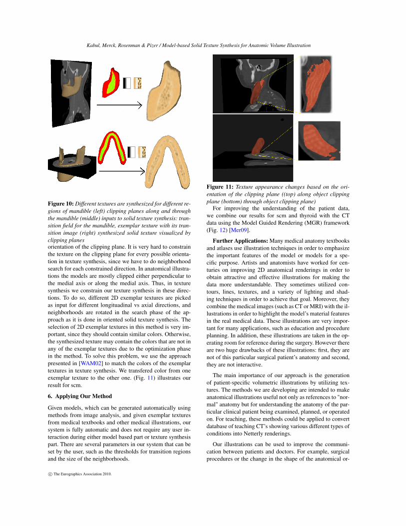
Synthesizing progressively variant textures can be applied tomany organ illustrations. For the illustration of the scm, thereare two different regions along the model. In our illustrationof the mandible, our objective is to obtain an illustration sim-ilar the one in [Net09] (Fig. 3). In the anatomic illustrationof the mandible, the texture elements are different for the in-ner layers (bone tissue) and outer layers (endosteum tissue).Both of these features are illustrated by synthesizing solidtextures for a specific patient‘s mandible using our approach(Fig. 9 and Fig. 10).
Figure 9: Different textures are synthesized along the modelfor different regions of scm
5.4. Model-based Texture Synthesis Control
In anatomical illustrations such as Fig. 3, the muscle tex-tures look different for different clipping planes. The impor-tant thing here is that the texture looks different based on the
c© The Eurographics Association 2010.
Kabul, Merck, Rosenman & Pizer / Model-based Solid Texture Synthesis for Anatomic Volume Illustration
Figure 10: Different textures are synthesized for different re-gions of mandible (left) clipping planes along and throughthe mandible (middle) inputs to solid texture synthesis: tran-sition field for the mandible, exemplar texture with its tran-sition image (right) synthesized solid texture visualized byclipping planesorientation of the clipping plane. It is very hard to constrainthe texture on the clipping plane for every possible orienta-tion in texture synthesis, since we have to do neighborhoodsearch for each constrained direction. In anatomical illustra-tions the models are mostly clipped either perpendicular tothe medial axis or along the medial axis. Thus, in texturesynthesis we constrain our texture synthesis in these direc-tions. To do so, different 2D exemplar textures are pickedas input for different longituadinal vs axial directions, andneighborhoods are rotated in the search phase of the ap-proach as it is done in oriented solid texture synthesis. Theselection of 2D exemplar textures in this method is very im-portant, since they should contain similar colors. Otherwise,the synthesized texture may contain the colors that are not inany of the exemplar textures due to the optimization phasein the method. To solve this problem, we use the approachpresented in [WAM02] to match the colors of the exemplartextures in texture synthesis. We transfered color from oneexemplar texture to the other one. (Fig. 11) illustrates ourresult for scm.
6. Applying Our Method
Given models, which can be generated automatically usingmethods from image analysis, and given exemplar texturesfrom medical textbooks and other medical illustrations, oursystem is fully automatic and does not require any user in-teraction during either model based part or texture synthesispart. There are several parameters in our system that can beset by the user, such as the thresholds for transition regionsand the size of the neighborhoods.
Figure 11: Texture appearance changes based on the ori-entation of the clipping plane ((top) along object clippingplane (bottom) through object clipping plane)
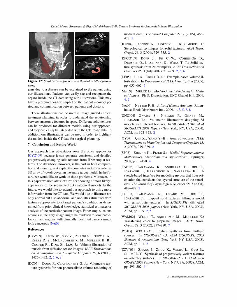
For improving the understanding of the patient data,we combine our results for scm and thyroid with the CTdata using the Model Guided Rendering (MGR) framework(Fig. 12) [Mer09].
Further Applications: Many medical anatomy textbooksand atlases use illustration techniques in order to emphasizethe important features of the model or models for a spe-cific purpose. Artists and anatomists have worked for cen-turies on improving 2D anatomical renderings in order toobtain attractive and effective illustrations for making thedata more understandable. They sometimes utilized con-tours, lines, textures, and a variety of lighting and shad-ing techniques in order to achieve that goal. Moreover, theycombine the medical images (such as CT or MRI) with the il-lustrations in order to highlight the model’s material featuresin the real medical data. These illustrations are very impor-tant for many applications, such as education and procedureplanning. In addition, these illustrations are taken in the op-erating room for reference during the surgery. However thereare two huge drawbacks of these illustrations: first, they arenot of this particular surgical patient’s anatomy and second,they are not interactive.
The main importance of our approach is the generationof patient-specific volumetric illustrations by utilizing tex-tures. The methods we are developing are intended to makeanatomical illustrations useful not only as references to "nor-mal" anatomy but for understanding the anatomy of the par-ticular clinical patient being examined, planned, or operatedon. For teaching, these methods could be applied to convertdatabase of teaching CT’s showing various different types ofconditions into Netterly renderings.
Our illustrations can be used to improve the communi-cation between patients and doctors. For example, surgicalprocedures or the change in the shape of the anatomical or-
c© The Eurographics Association 2010.
Kabul, Merck, Rosenman & Pizer / Model-based Solid Texture Synthesis for Anatomic Volume Illustration
Figure 12: Solid textures for scm and thyroid in MGR frame-workgans due to a disease can be explained to the patient usingour illustrations. Patients can easily see and recognize theorgans inside the CT data using our illustrations. This mayhave a profound positive impact on the patient recovery pe-riod and communication between patients and doctors.
These illustrations can be used in image guided clinicaltreatment planning in order to understand the relationshipbetween anatomic features in space. Different solid texturescan be produced for different models using our approach,and they can easily be integrated with the CT image data. Inaddition, our illustrations can be used in order to highlightthe models inside the CT data for surgical planning.
7. Conclusion and Future Work
Our approach has advantages over the other approaches[CYZ∗09] because it can generate consistent and detailedprogressively changing solid textures from 2D exemplar tex-tures. The drawback, however, is the cost in both computa-tion and memory, as it explicitly computes and stores a dense3D array of voxels covering the entire target model. In the fu-ture, we would like to work on these problems. Moreover, inthis paper we used atlas textures for showing a "most likely"appearance of the segmented 3D anatomical models. In thefuture, we would like to extend our approach to using moreinformation from the CT data. We would like to illustrate notonly normal but also abnormal and non-atlas structures withtextures appropriate to a target patient’s condition as deter-mined from prior clinical knowledge, statistical estimates oranalysis of the particular patient image. For example, lesionsobvious in the gray image might be rendered to look patho-logical, and regions with clinically identified cancers mightlook cancerous [Net09].
References
[CYZ∗09] CHEN W., YAN Z., ZHANG S., CROW J. A.,EBERT D. S., MCLAUGHLIN R. M., MULLINS K. B.,COOPER R., DING Z., LIAO J.: Volume illustration ofmuscle from diffusion tensor images. IEEE Transactionson Visualization and Computer Graphics 15, 6 (2009),1425–1432. 2, 5, 6, 8
[DC05] DONG F., CLAPWORTHY G. J.: Volumetric tex-ture synthesis for non-photorealistic volume rendering of
medical data. The Visual Computer 21, 7 (2005), 463–473. 3
[JDR04] JAGNOW R., DORSEY J., RUSHMEIER H.:Stereological techniques for solid textures. ACM Trans.Graph. 23, 3 (2004), 329–335. 2
[KFCO∗07] KOPF J., FU C.-W., COHEN-OR D.,DEUSSEN O., LISCHINSKI D., WONG T.-T.: Solid tex-ture synthesis from 2d exemplars. ACM Transactions onGraphics 26, 3 (July 2007), 2:1–2:9. 2, 5, 6
[LE05] LU A., EBERT D. S.: Example-based volume il-lustrations. In Proceedings of IEEE Visualization (2005),pp. 655–662. 3
[Mer09] MERCK D.: Model-Guided Rendering for Medi-cal Images. Ph.D. Dissertation, UNC Chapel Hill, 2009.4, 7
[Net09] NETTER F. H.: Atlas of Human Anatomy. Ritten-house Book Distributors Inc., 2009. 1, 3, 5, 6, 8
[ONOI04] OWADA S., NIELSEN F., OKABE M.,IGARASHI T.: Volumetric illustration: designing 3dmodels with internal textures. In SIGGRAPH ’04: ACMSIGGRAPH 2004 Papers (New York, NY, USA, 2004),ACM, pp. 322–328. 2
[QY07] QIN X., YANG Y.-H.: Aura 3d textures. IEEETransactions on Visualization and Computer Graphics 13,2 (2007), 379–389. 2
[SP08] SIDDIQI K., PIZER S.: Medial Representations:Mathematics, Algorithms and Applications. Springer,2008, pp. 1–450. 4
[TAI∗08] TAKAYAMA K., ASHIHARA T., IJIRI T.,IGARASHI T., HARAGUCHI R., NAKAZAWA K.: Asketch-based interface for modeling myocardial fiber ori-entation that considers the layered structure of the ventri-cles. The Journal of Physiological Sciences 58, 7 (2008),487–492. 2
[TOII08] TAKAYAMA K., OKABE M., IJIRI T.,IGARASHI T.: Lapped solid textures: filling a modelwith anisotropic textures. In SIGGRAPH ’08: ACMSIGGRAPH 2008 papers (New York, NY, USA, 2008),ACM, pp. 1–9. 2, 5
[WAM02] WELSH T., ASHIKHMIN M., MUELLER K.:Transferring color to greyscale images. ACM Trans.Graph. 21, 3 (2002), 277–280. 7
[Wei03] WEI L.-Y.: Texture synthesis from multiplesources. In SIGGRAPH ’03: ACM SIGGRAPH 2003Sketches & Applications (New York, NY, USA, 2003),ACM, pp. 1–1. 2
[ZZV∗03] ZHANG J., ZHOU K., VELHO L., GUO B.,SHUM H.-Y.: Synthesis of progressively-variant textureson arbitrary surfaces. In SIGGRAPH ’03: ACM SIG-GRAPH 2003 Papers (New York, NY, USA, 2003), ACM,pp. 295–302. 6
c© The Eurographics Association 2010.