Embed Size (px)
Citation preview

Model CC34IQSBENGLISH.....................................2FRANÇAIS.................................17ESPAÑOL..................................33
In USA - BEST Hartford, Wisconsin In CANADA - BEST Drummondville, QC, Canada
REGISTER YOUR PRODUCT ONLINE AT : www.BestRangeHoods.com/registerFor additional Information visit www.BestRangeHoods.com

- 2 -
READ AND SAVE THESE INSTRUCTIONS
WARNINGTO REDUCE THE RISK OF FIRE, ELECTRIC SHOCK, OR INJURY TO PERSONS, OBSERVE THE FOLLOWING:
1. Use this unit only in the manner intended by the manufacturer. If you have questions, contact the manufacturer at the address or telephone number listed in the warranty.
2. Before servicing or cleaning unit, switch power off at service panel and lock service panel to prevent power from being switched on accidentally. When the service disconnecting means cannot be locked, securely fasten a prominent warning device, such as a tag, to the service panel.
3. Installation work and electrical wiring must be done by a qualified person(s) in accordance with all applicable codes and standards, including fire-rated construction codes and standards.
4. Sufficient air is needed for proper combustion and exhausting of gases through the flue (chimney) of fuel burning equipment to prevent backdrafting. Follow the heating equipment manufacturer’s guidelines and safety standards such as those published by the National Fire Protection Association (NFPA), and the American Society for Heating, Refrigeration and Air Conditioning Engineers (ASHRAE), and the local code authorities.
5. When cutting or drilling into wall or ceiling, do not damage electrical wiring and other hidden utilities.
6. Ducted fans must always be vented to the outdoors.
7. Do not use this unit with any separate solid-state speed control device.
8. To reduce the risk of fire, use only metal ductwork.
9. This unit must be grounded.
10. Type Non-IC Installation: Thermal insulation shall not cover top of range hood housing and must be spaced 3-inches (76mm) from all sides. (Fig. 1)
! INTENDED FOR DOMESTIC COOKING ONLY !
3-INCH MINIMUM.NO INSULATION
WITHIN THIS SHADEDAREA OF COMPONENTS.
FIG. 1

- 3 -
! CAUTION1. For indoor use only.
2. To reduce risk of fire and to properly exhaust air, be sure to duct air outside. Do not vent exhaust air into spaces within walls or ceilings or into attics, crawl spaces, or garages.
3. Take care when using cleaning agents or detergents.
4. Avoid using food products that produce flames under the Range Hood.
5. For general ventilating use only. Do not use to exhaust hazardous or explosive materials and vapors.
6. To avoid motor bearing damage and noisy and/or unbalanced impellers, keep drywall spray, construction dust, etc. off power unit.
7. Your hood motor has a thermal overload which will automatically shut off the motor if it becomes overheated. The motor will restart when it cools down. If the motor continues to shut off and restart, have the hood serviced.
8. For best capture of cooking impurities, the bottom of the hood should be a minimum of 48” and a maximum of 72” above the cooking surface. See “Install Mounting Bracket” section for mounting restrictions.
9. Two installers are recommended because of the large size and weight of this hood.
10. The light source is designed for this specific application and can overheat if serviced by untrained personnel. If any servicing is required, the product should be returned to an authorized service facility for examination or repair.
11. Please read specification label on product for further information and requirements.
TO REDUCE THE RISK OF A RANGE TOP GREASE FIRE:
A. Never leave surface units unattended at high settings. Boilovers cause smoking and greasy spillovers that may ignite. Heat oils slowly on low or medium settings.
B. Always turn hood ON when cooking at high heat or when flambeing food (i.e. Crepes Suzette, Cherries Jubilee, Peppercorn Beef Flambe’).
C. Clean ventilating fans frequently. Grease should not be allowed to accumulate on fan or filter.
D. Use proper pan size. Always use cookware appropriate for the size of the surface element.
TO REDUCE THE RISK OF INJURY TO PERSONS IN THE EVENT OF A RANGE TOP GREASE FIRE, OBSERVE THE FOLLOWING:*
1. SMOTHER FLAMES with a close-fitting lid, cookie sheet, or metal tray, then turn off the burner. BE CAREFUL TO PREVENT BURNS. If the flames do not go out immediately, EVACUATE AND CALL THE FIRE DEPARTMENT.
2. NEVER PICK UP A FLAMING PAN - You may be burned.
3. DO NOT USE WATER, including wet dishcloths or towels - violent steam explosion will result.
4. Use an extinguisher ONLY if:A. You know you have a Class ABC extinguisher and you already know how to operate it.B. The fire is small and contained in the area where it started.C. The fire department is being called.D. You can fight the fire with your back to an exit.
* Based on “Kitchen Fire Safety Tips” published by NFPA.

- 4 -
OPERATION
Controls (Fig. 2)
The hood is operated using the (5) push-buttons located on the hood and the remote control.LED colors are displayed on hood control only.
FIG. 2
(P1) Delay- Off Switch• Yourhoodincludesa10minuteblowerdelayoffswitch.Pressthisswitchoncetoactivatethe
timer and the LED Ring (L1) flashes blue. The blower will continue to operate for 10 minutes. After 10 minutes, the blower turns off automatically.
• Tocancelthe10-minutedelay,pressthedelayswitchonceagain.
(P2) Filter Alarm Switch• After30hoursofbloweroperation,thefilteralarmisactivatedandtheLEDring(L1)turnsred/
flashes. It indicates that the grease filters need to be cleaned.• Aftercleaningthegreasefilters,resetthehourcounterbypressingtheFilterAlarm/TimerReset
button (P2) during display of the alarm.
(P3) Blower Speed Decrease and Off Switch • Press todecreaseblowerspeed,high to low.TheLED ring (L1) flashesblueataspeed
proportionate to the blower setting (i.e.: four flashes is high speed, one flash is low speed, etc.)• Continuepressingthisswitchtoturnthebloweroff.
(P4) Blower Speed Increase and On Switch• Pressthisswitchtoturntheblowerontolowspeed.• Pressagaintoincreaseblowerspeed,lowtohigh.TheLEDring(L1)flashesblueataspeed
proportionate to the blower setting (i.e.: four flashes is high speed, one flash is low speed, etc.)
(P5) Light SwitchTurns the lights on and off.
P1: Activate/deactivate delay-off (10 minute)
P2: Filter change indication timer reset
P3: Decreases fan motor speed until turned off (4>3>2>1>OFF)
P4: Turns fan motor on and increased speed (ON>1>2>3>4)
P5: Turns lights on/off
L1: LED Indicator Ring Signalling crown:
- Hood in standby: lights up green. 30 seconds after
the last key has been pressed the crown turns off
- Motor on: L1 lights up blue The
frequency is proportional to the speed setting.
- 10’ TIMER function : L1 lights up and flashes blue.
- Filter alarm active: L1 lights up red
L1LEDRING
+-
ƒ
¤ (P1)
(P2)
(P3)
(P4)(P5)
Auto Shut-Off Feature
If the blower and/or the lights are on continuously for 10 hours without any user interaction with the controls, the hood will automatically shut off. Press any control button to re-activate the hood.

- 5 -
HOODCONTROL
REMOTE CONTROL
The remote control is linked to the hood at the factory.
If, for some reason, the link is lost - follow the directions below:
To Link Remote Control to Hood
1. Turn off hood motor and hood lights.
2. Press
on the remote control for at least 3 seconds. The indicator light will light up. (Fig. 3)
3. While holding
on the remote control - press ƒ (P2) on the hood control. (Fig. 4) The LED
ring will light up GREEN for approximately 10 seconds to confim that the linking process was
successful.
P1: Activate/deactivate delay-off (10 minute)
P2: Filter change indication timer reset
P3: Decreases fan motor speed until turned off (4>3>2>1>OFF)
P4: Turns fan motor on and increased speed (ON>1>2>3>4)
P5: Turns lights on/off
L1: LED Indicator Ring Signalling crown:
- Hood in standby: lights up green. 30 seconds after
the last key has been pressed the crown turns off
- Motor on: L1 lights up blue The
frequency is proportional to the speed setting.
- 10’ TIMER function : L1 lights up and flashes blue.
- Filter alarm active: L1 lights up red
L1LEDRING
+-
ƒ
¤ (P1)
(P2)
(P3)
(P4)(P5)
INDICATORLIGHT
FIG. 4FIG. 3
P1
P2
P3 P4
P5
- 23A
+
P1
P2
P4
P3
HOODP1: 5' TIMER function activation/deactivation.
hood sensor: AUTOMATIC function activation/deactivation.
P2: Motor off/motor speed decrease.P3: Motor on/motor speed increase.P4: Lights on/off.
As soon as the button ispressed, the circular crownlights up for 1".
Battery disposalWhen the batteries need to be replaced, dispose of them only and exclusively in the numerous readily availablespecial waste bins, especially in shops selling electronic consumer goods. Observance of the regulations ondifferentiated waste collection, in particular, proper disposal of used batteries, contributes to preventing possiblenegative effects on the environment and health.
LINKING procedure- To unambiguously associate the radio control with
the hood, you can activate a LINKING procedure.Once the procedure has terminated, the radiocontrol functions only and exclusively with theassociated product.
- This procedure is useful if there are two or moreproducts that can be controlled by means of radiocontrol, for example, in apartments with adjacentkitchens, showrooms, fairs, etc.
1 - Turn off the hood motor and the lights2 - Press P1 for 3": the circular crown will light up3 - Confirm the link to the hood within 3" by pressing
the button indicated on the next page.
Confirm P2
CAUTION RISK OF EXPLOSION IF BATTERY ISREPLACED BY AN INCORRECT TYPE. DISPOSEOF USED BATTE TO THE INSTRUCTION.
Remote Control Functions (Fig.3)
Delay - Off
Blower Speed Decrease and Off
Blower Speed Increase and On
Light
P1
P2
P3 P4
P5
- 23A
+
P1
P2
P4
P3
HOODP1: 5' TIMER function activation/deactivation.
hood sensor: AUTOMATIC function activation/deactivation.
P2: Motor off/motor speed decrease.P3: Motor on/motor speed increase.P4: Lights on/off.
As soon as the button ispressed, the circular crownlights up for 1".
Battery disposalWhen the batteries need to be replaced, dispose of them only and exclusively in the numerous readily availablespecial waste bins, especially in shops selling electronic consumer goods. Observance of the regulations ondifferentiated waste collection, in particular, proper disposal of used batteries, contributes to preventing possiblenegative effects on the environment and health.
LINKING procedure- To unambiguously associate the radio control with
the hood, you can activate a LINKING procedure.Once the procedure has terminated, the radiocontrol functions only and exclusively with theassociated product.
- This procedure is useful if there are two or moreproducts that can be controlled by means of radiocontrol, for example, in apartments with adjacentkitchens, showrooms, fairs, etc.
1 - Turn off the hood motor and the lights2 - Press P1 for 3": the circular crown will light up3 - Confirm the link to the hood within 3" by pressing
the button indicated on the next page.
Confirm P2
CAUTION RISK OF EXPLOSION IF BATTERY ISREPLACED BY AN INCORRECT TYPE. DISPOSEOF USED BATTE TO THE INSTRUCTION.
Note: Filter reset is not possible with the remote.
See “Controls” section on previous page for more information on each function.

- 6 -
CLEANING AND MAINTENANCEProper maintenance of the Range Hood will assure proper performance of the unit.
MotorThe motor is permanently lubricated and never needs oiling. If the motor bearings make excessive or unusual noise, replace the motor with the exact service motor. The impeller should also be replaced.
Grease FiltersThe grease filters should be cleaned frequently. Use a warm detergent solution. Grease filters are dishwasher safe.
Clean all-metal filters in the dishwasher using a non-phosphate detergent. Discoloration of the filter may occur if using phosphate detergents, or as a result of local water conditions - but this will not affect filter performance. This discoloration is not covered by the warranty.See “INSTALL FILTERS” section for removal and installation instructions.
Stainless Steel Cleaning
DO:
• Regularlywashwithcleanclothorragsoakedwith warm water and mild soap or liquid dish detergent.
• Alwayscleaninthedirectionoforiginalpolishlines.
• Alwaysrinsewellwithclearwater(2or3times)after cleaning. Wipe dry completely.
• Youmayalsousea specializedhouseholdstainless steel cleaner.
DON’T:
• Use any steel or stainless steel wool or any other scrapers to remove stubborn dirt.
• Useanyharshorabrasivecleansers.
• Allowdirttoaccumulate.
• Let plaster dust or any other constructionresidues reach the hood. During construction/renovation, cover the range hood to make sure no dust sticks to the stainless steel surface.
Avoid: When choosing a detergent• Anycleanersthatcontainbleachwillattackstainlesssteel• Anyproductscontaining:chloride,fluoride,iodide,bromidewilldeterioratesurfacesrapidly.• Anycombustibleproductsusedforcleaningsuchasacetone,alcohol,ether,benzol,etc.,arehighly
explosive and should never be used close to a range.

- 7 -
PREPARE THE HOODUnpack hood and check contents.
You should receive: 1 - Range Hood Body 1 - Remote Control 6 - Grease Filters 2 - Screws, 4 x 9.5 mm
6 - Lag Bolts, 6 x 70 mm 6 - Washers
6 LAG BOLTS(6 x 70 mm)
FIG. 5
REMOTECONTROL
RANGE HOODBODY with DAMPER
6 GREASE FILTERS
6 WASHERS
2 SCREWS(4 x 9.5 mm)

- 8 -
INSTALL THE DUCTWORK
FIG. 6
ROOF CAP
48" TO 72" ABOVECOOKING SURFACE
HOOD
8" ROUNDDUCT
8" ROUNDTO 3¼” X 14”
REDUCER
3¼” X 14”UNDEREAVEVENT
8" ROUNDDUCT
WARNING: To reduce the risk of fire, use only metal duc-twork.
1. Decide where the ductwork will run between the hood and the outside. Fig. 6.
2. A straight, short duct run will allow the hood to perform most efficiently.
3. Long duct runs, elbows, and transitions will reduce the per-formance of the hood. Use as few of them as possible. Larger ducting may be required for best performance with longer duct runs.
4. Install a roof cap, wall cap, or under-eave vent. Connect round metal ductwork to cap/vent and work back towards hood location. Use duct tape to seal the joints between ductwork sections.
5. The blower can be rotated according to the air outlet location. See Fig. 7 for air outlet dimensions.
8¾”
13¾”
8¾”
2111/16”
FIG. 7
- OR -
LOCATION OF HOOD OUTLET

- 9 -
PREPARE THE HOOD SUPPORT1. Construct a wood framing system
as shown in Fig. 9.
2. The structure must be capable of supporting its own weight, plus the weight of the hood (64 pounds).
FIG. 9
2 x 4FRAMING
37-1/4”
42-1/2”
14”
26-3/4”
2-5/8”
1/8” PILOTHOLE (6)
11” 11”11” 11”
1/8” PILOTHOLE (6)
PREPARE THE CEILING OPENINGThe hood should always be centered over the cooktop. Make sure there is adequate space in the ceiling structure to install the hood and ductwork. The hood should be mounted 48” to 72” above the cook top for best removal of cooking impurities. Fig 6.
Use joist size lumber to frame in around the range hood opening. The ceiling structure must be able to support the weight of the hood (64 pounds). Fig 8.
FIG. 8
DOUBLE HEADERS
421 /2”
26¾”

- 10 -
ATTACH CONTROL BOX
1. Remove control box from side of blower box. Fig. 10.
2. Insert control box into opening. Fig. 11.
3. Attach control box with (2) 4 x 9.5 mm screws provided. Fig. 12.
FIG. 10
FIG. 11
FIG. 12
CONTROL BOXTAPED TO
BLOWER HOUSING
CONTROL BOX
OPENINGIN HOOD
ATTACH SCREWSON FILTER SIDE
(2) 4mm X 9.5mm SCREWS

- 11 -
INSTALL THE HOOD CAUTION: At least two installers are
recommended because of the large size and weight of this range hood.
1. Hood is shipped in the horizontal duct discharge position and is ready to be installed.
2. To change direction of the duct without using elbows. Fig. 13:
• Remove(2)screwsfrominsideofblowerbox.
• Remove(4)screwsfromsidesofblowerbox.
• Removeblower,turnblower90degrees,reinstall (4) screws.
3. Lift range hood into the ceiling opening.
4. Secure each support frame to the wooden hood support frame using (6) 6 x 70 mm lag bolts and washers provided. Fig. 14.
5. Adjust height of the telescoping support frame to ensure a tight fit between the hood and finished ceiling.
6. At the blower discharge collar, connect ductwork that exhausts air to the outside discharge.
7. Duct tape all joints to ensure an air tight seal.
FIG. 13
SCREWS (4)
FIG. 14
2 X 4 WOODFRAME
(6) WASHERS& LAG BOLTS
CONNECT THE WIRING
WARNING: All electrical wiring should be done by a qualified person (s) in accordance with all applicable codes and standards. This range hood must be properly grounded.
Do not turn blower on at the service panel until all wires have been connected.
1. Run 2-wire plus ground, 120 VAC electrical power cable to the ¾” knockout located on the back of the hood. Fig. 15.
2. Remove ¾” electrical knockout from the back of the hood. FIG. 15
2-WIRE PLUSGROUND120 VACLINE IN
KNOCKOUT

- 12 -
CONNECT WHITE-TO-WHITE,BLACK-TO-BLACK, GREEN-TO-GROUND
FIG. 16
FIG. 17
120 VACLINE IN
BOX MARKED “120VAC INPUT”
3. From the room interior, pull down both closure panels. Fig. 16.
4. Remove (4) screws from the electrical compartment access panel. Slide the panel sideways to expose the electrical wiring box.
5. From the electrical box marked “120 VAC Inlet”, remove (2) screws that secure the cover to the metal wiring box. Fig. 17.
6. Pull 120VAC electrical power cable into the box and secure with an appropriate cable clamp.
7. Make electrical connections inside the box. Connect white-to-white, black-to-black and green-to-ground.
8. Replace the wiring box cover and the screws. Make sure wires are not pinched between the cover and box.
9. Replace the electrical compartments ac-cess panel and (4) screws.
MAKE-UP AIR DAMPER
The hood is compatible with Broan Make-Up Air Damper Model MD6T, Model MD8T or Model MD10T (optional). Purchase separately.
Make the connection to the Make-Up Air Damper with low voltage wiring, as shown. See Make-Up Air Damper instructions for additional information. (Fig. 18)
MAKE-UP AIR DAMPER
HOOD
24VTRANSFORMER(INCLUDED)
GRD
WIRE BOXFOR LOWVOLTAGE CONNECTION
MAKE UP DAMPER CONNECTION(switched low voltage)
20 GAUGE BELL WIRE FOR LOWVOLTAGE CONNECTION ONTOP OF HOOD
120 VAC60 HZ
FIG. 18

- 13 -
INSTALL THE FILTERS1. Pull down both closure panels as shown.
Fig. 19 and Fig. 20.
2. To install the grease filters, align rear filter tabs with slots in the hood. Push latch tab in, push filter into position and release. Make sure filter is securely engaged after installation.
3. To remove the filters for cleaning, push latch tab in to disengage filter from hood. Tilt the filter downward and remove.
FIG. 19
FIG. 20CALIBRATE IQ BLOWER SYSTEM TM
INTERNAL BLOWER DUCTED UNITS ONLY
After the hood is installed and wired, engage the calibration process (our Guaranteed Performance System Technology to ensure full-rated airflow is being delivered). Prior to calibration, ensure that all filters and the duct system are installed.
CALIBRATION PROCESS Fig. 21.
Open the bottom panel. Hold the calibration button for 3 seconds and the calibration button will light up. Close the bottom panel. The blower will start and begin the calibration process - which will take approximately 13 minutes. When calibration is complete, one of two things will occur:
A. The blower turns off and calibration button light turns off = Successful calibration.
B. The blower turns off and calibration button light blinks continuously = Too much restriction in the ductwork is preventing the IQ Blower System™ from achieving the rated airflow. The blower is automatically set to maximum intensity.
NOTE: Common items that cause restrictions: restricted damper flap (backdraft damper, wall cap, roof cap), too many elbows, duct size less than 80% of hood outlet, poor transition,
FIG. 21
CALIBRATIONBUTTON
CALIBRATIONLIGHT
use of flex ducting and/or crushed ducting.
Two options are available:1. Press the calibration button to accept
airflow as is. The IQ Blower System™ is now configured to its highest possible setting. The blinking calibration light goes out.
2. Correct duct restriction and repeat the calibration process. a. To clear the original calibration data, hold calibration button for 10 seconds. The light will blink 3 times to confirm and the blower configuration will go back to default settings. b. Repeat calibration process.

- 14 -
SERVICE PARTS
KEY NO. DESCRIPTION PART NO.
CAS BLOWER ASSEMBLY 06002259 506 BLDC DRIVER 97019431 67 WIRES 06102601 202 WIRE CLAMP 03292290 415 BUSHING 03202288 IME ELECTRICAL INSTALLATION ASSEMBLY 06145222 67A WIRES 06102598 115 FEEDER CABLE CONNECTION BOX E3350233 415 BUSHING 03292596 116 FEEDER CABLE CONNECTION BOX COVER E3351530 125 UPPER TELESCOPIC SKELETON 08092797 124 BOTTOM TELESCOPIC SKELETON E3404965 64 BOTTOM BRACKET 03115251 507 CALIBRATION BUTTON ASSEMBLY 06102584 439 GROMMET 02320034 474 LED LIGHT 02300885 250 RING NUT 02011389 AQI SWITCH BOX ASSEMBLY 06102585 343 CLOSURE PANEL 08093076 477 HINGE 02011376 362 DISPLAY VISOR SPRING 02011421 9 GREASE FILTER 08087804 ARU CONNECTION AIR OUTLET SET 08092501 ACR2 REMOTE CONTROL 08999166 HARDWARE 080810994 INSTALLATION INSTRUCTIONS 080813623
Model CC34IQSB

- 15 -
SERVICE PARTS
Model CC34IQSB
CAS
125
124
474
477
343
2509
AQI
IME
US-CIRRUS BLDC
64
362
439
507
506
202
ARU
202
116
202
115
415 (03202288)
415 (03202288)
415 (03202288)
(03292596) 415
(03202288) 415
(03202288) 415
(03202288) 415
ACR2
67 (06102601)
67A (06102598)

- 16 -99045156C
WARRANTY
Limited WarrantyWarranty Period and Exclusions: Broan-NuTone LLC (the “Company”) warrants to the original consumer purchaser of its product (“you”) that the product (the “Product”) will be free from material defects in the Product or its workmanship for a period of one (1) year from the date of original purchase.The limited warranty period for any replacement parts provided by the Company and for any Products repaired or replaced under this limited warranty shall be the remainder of the original warranty period.This warranty does not cover fluorescent lamp starters, tubes, halogen and incandescent bulbs, fuses, filters, ducts, roof caps, wall caps and other accessories for ducting that may be purchased separately and installed with the Product. This warranty also does not cover (a) normal maintenance and service, (b) normal wear and tear, (c) any Products or parts which have been subject to misuse, abuse, abnormal usage, negligence, accident, improper or insufficient maintenance, storage or repair (other than repair by the Company), (d) damage caused by faulty installation, or installation or use contrary to recommendations or instructions, (e) any Product that has been moved from its original point of installation, (f) damage caused by environmental or natural elements, (g) damage in transit, (h) natural wear of finish, (i) Products in commercial or nonresidential use, or (j) damage caused by fire, flood or other act of God. This warranty covers only Products sold to original consumers in the United States by the Company or U.S. distributors authorized by the Company.This warranty supersedes all prior warranties and is not transferable from the original consumer purchaser.No Other Warranties: This Limited Warranty contains the Company’s sole obligation and your sole remedy for defective products. The foregoing warranties are exclusive and in lieu of any other warranties, express or implied. THE COMPANY DISCLAIMS AND EXCLUDES ALL OTHER EXPRESS WARRANTIES, AND DISCLAIMS AND EXCLUDES ALL WARRANTIES IMPLIED BY LAW, INCLUDING WITHOUT LIMITATION THOSE OF MERCHANTABILITY AND FITNESS FOR A PARTICULAR PURPOSE. To the extent that applicable law prohibits the exclusion of implied warranties, the duration of any applicable implied warranty is limited to the period specified for the express warranty above. Some states do not allow limitations on how long an implied warranty lasts, so the above limitation may not apply to you. Any oral or written description of the Product is for the sole purpose of identifying it and shall not be construed as an express warranty.Whenever possible, each provision of this Limited Warranty shall be interpreted in such manner as to be effective and valid under applicable law, but if any provision is held to be prohibited or invalid, such provision shall be ineffective only to the extent of such prohibition or invalidity, without invalidating the remainder of such provision or the other remaining provisions of the Limited Warranty.Remedy: During the applicable limited warranty period, the Company will, at its option, provide replacement parts for, or repair or replace, without charge, any Product or part thereof, to the extent the Company finds it to be covered by and in breach of this limited warranty under normal use and service. The Company will ship the repaired or replaced Product or replacement parts to you at no charge. You are responsible for all costs for removal, reinstallation and shipping, insurance or other freight charges incurred in the shipment of the Product or part to the Company. If you must send the Product or part to the Company, as instructed by the Company, you must properly pack the Product or part—the Company is not responsible for damage in transit. The Company reserves the right to utilize reconditioned, refurbished, repaired or remanufactured Products or parts in the warranty repair or replacement process. Such Products and parts will be comparable in function and performance to an original Product or part and warranted for the remainder of the original warranty period.Exclusion of Damages: THE COMPANY’S OBLIGATION TO PROVIDE REPLACEMENT PARTS, OR REPAIR OR REPLACE, AT THE COMPANY’S OPTION, SHALL BE YOUR SOLE AND EXCLUSIVE REMEDY UNDER THIS LIMITED WARRANTY AND THE COMPANY’S SOLE AND EXCLUSIVE OBLIGATION. THE COMPANY SHALL NOT BE LIABLE FOR INCIDENTAL, INDIRECT, CONSEQUENTIAL OR SPECIAL DAMAGES ARISING OUT OF OR IN CONNECTION WITH THE PRODUCT, ITS USE OR PERFORMANCE.Some states do not allow the exclusion or limitation of incidental or consequential damages, so the above limitation or exclusion may not apply to you. This warranty gives you specific legal rights, and you may also have other rights, which vary from state to state.This warranty covers only replacement or repair of defective Products or parts thereof at the Company’s main facility and does not include the cost of field service travel and living expenses.Any assistance the Company provides to or procures for you outside the terms, limitations or exclusions of this limited warranty will not constitute a waiver of such terms, limitations or exclusions, nor will such assistance extend or revive the warranty.The Company will not reimburse you for any expenses incurred by you in repairing or replacing any defective Product, except for those incurred with the Company’s prior written permission.How to Obtain Warranty Service: To qualify for warranty service, you must (a) notify the Company at the address or telephone number stated below within seven (7) days of discovering the covered defect, (b) give the model number and part identification and (c) describe the nature of any defect in the Product or part. At the time of requesting warranty service, you must present evidence of the original purchase date. If you cannot provide a copy of the original written limited warranty, then the terms of the Company’s most current written limited warranty for your particular product will control. The most current limited written warranties for the Company’s products can be found at www.BestRangeHoods.com.In USA - BEST® Hartford, Wisconsin 800-558-1711 In Canada - BEST® Drummondville, QC 866-737-7770 www.BestRangeHoods.com

- 17 -
Modèle CC34IQSBENGLISH.....................................2FRANÇAIS.................................17ESPAÑOL..................................33
Aux États-Unis - BEST Hartford, Wisconsin Au CANADA - BEST Drummondville, QC, Canada
ENREGISTREZ VOTRE PRODUIT EN LIGNE À : www.BestRangeHoods.com/registerPour de plus amples informations, visitez www.BestRangeHoods.com

- 18 -
LIRE CES DIRECTIVES ET LES CONSERVER
AVERTISSEMENTOBSERVEZ LES DIRECTIVES CI-DESSOUS AFIN DE RÉDUIRE LES RISQUES D’INCENDIE, DE CHOC ÉLECTRIQUE OU DE BLESSURES CORPORELLES :
1. N’utilisez cet appareil que de la manière prévue par le fabricant. Si vous avez des questions, communiquez avec le fabricant à l’adresse ou au numéro de téléphone indiqués dans la garantie.
2. Avant de procéder à la réparation ou à l’entretien de l’appareil, coupez l’alimentation du panneau électrique et verrouillez l’interrupteur principal afin d’empêcher que le courant ne soit accidentellement rétabli. S’il est impossible de verrouiller l’interrupteur principal, fixez solidement un message d’avertissement, par exemple une étiquette, sur le panneau électrique.
3. La pose de l’appareil et les travaux d’électricité doivent être effectués par des personnes qualifiées conformément à la réglementation en vigueur, notamment les normes de la construction ayant trait à la protection contre les incendies.
4. Pour éviter les refoulements, l’apport d’air doit être suffisant pour brûler les gaz produits par les appareils à combustion et les évacuer dans le conduit de fumée (cheminée). Respectez les directives du fabricant de l’appareil de chauffage et les normes de sécurité, notamment celles publiées par la National Fire Protection Association (NFPA), l’American Society for Heating, Refrigeration and Air Conditioning Engineers (ASHRAE) et les codes des autorités locales.
5. Veillez à ne pas endommager le câblage électrique ou d’autres équipements non apparents lors de la découpe ou du perçage du mur ou du plafond.
6. Les ventilateurs canalisés doivent toujours rejeter l’air à l’extérieur.
7. N’utilisez pas de commande de régime à semi-conducteurs conjointement avec cet appareil.
8. Pour réduire les risques d’incendie, utilisez seulement des conduits en métal.
9. Cet appareil doit être relié à une mise à la terre.
10. Type d’installation non-IC : L’isolant thermique de la maison ne doit pas couvrir le haut de la hotte et doit être à au moins 76 mm (3 po) du boîtier de tout côté. (Fig. 1)
! POUR USAGE DOMESTIQUE SEULEMENT !
MINIMUM 76 MM (3 PO). PAS D’ISOLANT DANS CETTE
ZONE OMBRÉE.
FIG. 1

- 19 -
! ATTENTION1. Pour usage intérieur seulement.
2. Pour réduire les risques d’incendie et évacuer l’air correctement, assurez-vous qu’il est canalisé à l’extérieur. N’évacuez pas l’air dans des espaces enfermés par des murs ou un plafond ou dans un grenier, un vide sanitaire ou un garage.
3. Faites attention lorsque vous utilisez des agents nettoyants ou des détergents.
4. Évitez d’utiliser des produits alimentaires pouvant produire des flammes sous la hotte.
5. Pour ventilation générale uniquement. N’utilisez pas cet appareil pour évacuer des matières ou des vapeurs dangereuses ou explosives.
6. Pour éviter d’endommager les roulements de moteur, de déséquilibrer les pales ou de les rendre bruyantes, débarrassez l’appareil de la poussière de plâtre, de construction, etc.
7. Le moteur de la hotte est muni d’un dispositif de protection thermique qui coupe automatiquement le moteur en cas de surchauffe. Il se remet en marche lorsqu’il a refroidi. Faites réparer la hotte si le moteur continue à fonctionner par intermittence.
8. Pour mieux capter les vapeurs de cuisson, le bas de la hotte doit être au minimum à 122 cm (48 po) et au maximum à 183 cm (72 po) de la surface de cuisson. Pour les restrictions s’appliquant au montage, voir la section « Installation de la bride de montage ».
9. Il est recommandé d’avoir deux installateurs, compte tenu de la taille et du poids de cette hotte.
10. La source d’éclairage est conçue pour cette application particulière et peut surchauffer si elle est réparée par un personnel sans formation. Si une réparation est nécessaire, le produit doit être retourné à un centre de service agréé pour être examiné ou réparé.
11. Veuillez lire l’étiquette de spécifications du produit pour obtenir plus de renseignements, notamment sur les exigences.
POUR RÉDUIRE LES RISQUES D’INCENDIE CAUSÉS PAR DE LA GRAISSE SUR LE PLAN DE CUISSON :
A. Ne laissez jamais les éléments de surface allumés à haute température. Les débordements peuvent causer de la fumée et occasionner des écoulements de graisse inflammables. L’huile doit être chauffée graduellement à basse ou à moyenne température.
B. Mettez toujours la hotte en MARCHE lors de la cuisson à feu vif ou lors de la cuisson d’aliments à flamber (par ex., crêpes Suzette, cerises jubilé, bœuf au poivre flambé).
C. Nettoyez souvent les ventilateurs. Ne laissez pas la graisse s’accumuler sur le ventilateur ou les filtres.
D. Utilisez des casseroles de dimension appropriée. Utilisez toujours une batterie de cuisine adaptée à la dimension de la surface chauffante.
OBSERVEZ LES CONSIGNES SUIVANTES DE MANIÈRE À RÉDUIRE LES RISQUES DE BLESSURES CORPORELLES EN CAS D’INCENDIE CAUSÉ PAR DE LA GRAISSE SUR LE PLAN DE CUISSON* :
1. ÉTOUFFEZ LES FLAMMES à l’aide d’un couvercle étanche, d’une tôle à biscuits ou d’un plateau en métal puis éteignez le brûleur. FAITES ATTENTION DE NE PAS VOUS BRÛLER. Si les flammes ne s’éteignent pas immédiatement, QUITTEZ LES LIEUX ET APPELEZ LE SERVICE DES INCENDIES.
2. NE SOULEVEZ JAMAIS UNE CASSEROLE EN FLAMMES - vous pourriez vous brûler.3. N’UTILISEZ PAS D’EAU, ni de serviettes ou de linges mouillés – une violente explosion de vapeur
pourrait survenir.4. Utilisez un extincteur SEULEMENT si :
A. Vous savez qu’il est de classe ABC et vous connaissez déjà son mode de fonctionnement.B. L’incendie n’est pas très important et ne se propage pas.C. Les pompiers ont été avisés.D. Vous pouvez combattre l’incendie en faisant dos à une sortie.
* Conseils tirés de la publication de la NFPA « Kitchen Fire Safety Tips ».
- 20 -
FONCTIONNEMENT
Commandes (Fig. 2)
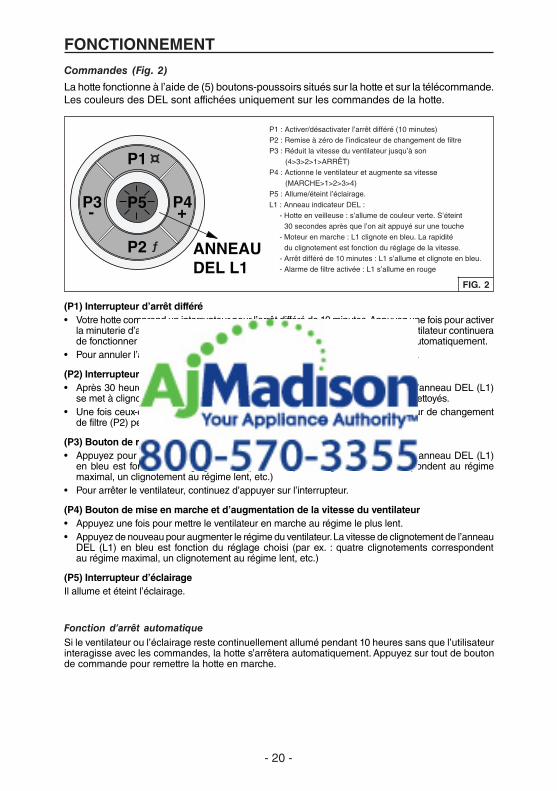
La hotte fonctionne à l’aide de (5) boutons-poussoirs situés sur la hotte et sur la télécommande.Les couleurs des DEL sont affichées uniquement sur les commandes de la hotte.
FIG. 2
(P1) Interrupteur d’arrêt différé• Votrehottecomprenduninterrupteurpourl’arrêtdifféréde10minutes.Appuyezunefoispouractiver
la minuterie d’arrêt différé et l’anneau DEL (L1) se met à clignoter en bleu. Le ventilateur continuera de fonctionner pendant dix minutes. Après dix minutes, le ventilateur s’arrêtera automatiquement.
• Pourannulerl’arrêtdifférédedixminutes,appuyezdenouveausurl’interrupteur.
(P2) Interrupteur d’alarme de filtre• Après30heuresdefonctionnementduventilateur,l’alarmedefiltres’activeetl’anneauDEL(L1)
se met à clignoter en rouge. Cela indique que les filtres à graisses doivent être nettoyés.• Unefoisceux-cinettoyés,appuyezsurleboutonderemiseàzérodel’indicateurdechangement
de filtre (P2) pendant l’affichage de l’alarme.
(P3) Bouton de réduction de la vitesse du ventilateur et d’arrêt • Appuyezpourréduirelavitesseduventilateur.Lavitessedeclignotementdel’anneauDEL(L1)
en bleu est fonction du réglage choisi (par ex. : quatre clignotements correspondent au régime maximal, un clignotement au régime lent, etc.)
• Pourarrêterleventilateur,continuezd’appuyersurl’interrupteur.
(P4) Bouton de mise en marche et d’augmentation de la vitesse du ventilateur• Appuyezunefoispourmettreleventilateurenmarcheaurégimelepluslent.• Appuyezdenouveaupouraugmenterlerégimeduventilateur.Lavitessedeclignotementdel’anneau
DEL (L1) en bleu est fonction du réglage choisi (par ex. : quatre clignotements correspondent au régime maximal, un clignotement au régime lent, etc.)
(P5) Interrupteur d’éclairageIl allume et éteint l’éclairage.
P1
P2
P3 P4
ANNEAU DEL L1
P5+-
ƒ
¤
P1 : Activer/désactivater l’arrêt différé (10 minutes) P2 : Remise à zéro de l’indicateur de changement de filtre P3 : Réduit la vitesse du ventilateur jusqu’à son
(4>3>2>1>ARRÊT) P4 : Actionne le ventilateur et augmente sa vitesse
(MARCHE>1>2>3>4) P5 : Allume/éteint l’éclairage. L1 : Anneau indicateur DEL : - Hotte en veilleuse : s’allume de couleur verte. S’éteint
30 secondes après que l’on ait appuyé sur une touche - Moteur en marche : L1 clignote en bleu. La rapidité
du clignotement est fonction du réglage de la vitesse. - Arrêt différé de 10 minutes : L1 s’allume et clignote en bleu. - Alarme de filtre activée : L1 s’allume en rouge
Fonction d’arrêt automatiqueSi le ventilateur ou l’éclairage reste continuellement allumé pendant 10 heures sans que l’utilisateur interagisse avec les commandes, la hotte s’arrêtera automatiquement. Appuyez sur tout de bouton de commande pour remettre la hotte en marche.

- 21 -
PANNEAU DE COMMANDE DE
LA HOTTE
TÉLÉCOMMANDE
La télécommande est jumelée à la hotte dès sa sortie de l’usine.Si pour une raison quelconque cette liaison est perdue – veuillez suivre les directives ci-dessous :
Liaison de la télécommande à la hotte
1. Arrêtez le moteur de la hotte et éteignez l’éclairage.
2. Appuyez sur le bouton de la télécommande pendant au moins 3 secondes. Le témoin lumineux s’allume. (Fig. 3)
3. Tout en maintenant le bouton de la télécommande, appuyez sur ƒ (P2) sur le panneau de commande de la hotte. (Fig. 4) L’anneau DEL clignotera en VERT pendant environ 10 secondes pour confirmer que la liaison a réussi.
P1
P2
P3 P4
ANNEAU DEL L1
P5+-
ƒ
¤
P1 : Activer/désactivater l’arrêt différé (10 minutes) P2 : Remise à zéro de l’indicateur de changement de filtre P3 : Réduit la vitesse du ventilateur jusqu’à son
(4>3>2>1>ARRÊT) P4 : Actionne le ventilateur et augmente sa vitesse
(MARCHE>1>2>3>4) P5 : Allume/éteint l’éclairage. L1 : Anneau indicateur DEL : - Hotte en veilleuse : s’allume de couleur verte. S’éteint
30 secondes après que l’on ait appuyé sur une touche - Moteur en marche : L1 clignote en bleu. La rapidité
du clignotement est fonction du réglage de la vitesse. - Arrêt différé de 10 minutes : L1 s’allume et clignote en bleu. - Alarme de filtre activée : L1 s’allume en rouge
TÉMOIN LUMINEUX
FIG. 4FIG. 3
P1
P2
P3 P4
P5
- 23A
+
P1
P2
P4
P3
HOODP1: 5' TIMER function activation/deactivation.
hood sensor: AUTOMATIC function activation/deactivation.
P2: Motor off/motor speed decrease.P3: Motor on/motor speed increase.P4: Lights on/off.
As soon as the button ispressed, the circular crownlights up for 1".
Battery disposalWhen the batteries need to be replaced, dispose of them only and exclusively in the numerous readily availablespecial waste bins, especially in shops selling electronic consumer goods. Observance of the regulations ondifferentiated waste collection, in particular, proper disposal of used batteries, contributes to preventing possiblenegative effects on the environment and health.
LINKING procedure- To unambiguously associate the radio control with
the hood, you can activate a LINKING procedure.Once the procedure has terminated, the radiocontrol functions only and exclusively with theassociated product.
- This procedure is useful if there are two or moreproducts that can be controlled by means of radiocontrol, for example, in apartments with adjacentkitchens, showrooms, fairs, etc.
1 - Turn off the hood motor and the lights2 - Press P1 for 3": the circular crown will light up3 - Confirm the link to the hood within 3" by pressing
the button indicated on the next page.
Confirm P2
CAUTION RISK OF EXPLOSION IF BATTERY ISREPLACED BY AN INCORRECT TYPE. DISPOSEOF USED BATTE TO THE INSTRUCTION.
Fonctions de la télécommande (Fig.3)
Arrêt différé – Désactivé Bouton de réduction de la vitesse
du ventilateur et d’arrêt
Bouton de mise en marche et d’augmentation de la vitesse du ventilateur
Éclairage
P1
P2
P3 P4
P5
- 23A
+
P1
P2
P4
P3
HOODP1: 5' TIMER function activation/deactivation.
hood sensor: AUTOMATIC function activation/deactivation.
P2: Motor off/motor speed decrease.P3: Motor on/motor speed increase.P4: Lights on/off.
As soon as the button ispressed, the circular crownlights up for 1".
Battery disposalWhen the batteries need to be replaced, dispose of them only and exclusively in the numerous readily availablespecial waste bins, especially in shops selling electronic consumer goods. Observance of the regulations ondifferentiated waste collection, in particular, proper disposal of used batteries, contributes to preventing possiblenegative effects on the environment and health.
LINKING procedure- To unambiguously associate the radio control with
the hood, you can activate a LINKING procedure.Once the procedure has terminated, the radiocontrol functions only and exclusively with theassociated product.
- This procedure is useful if there are two or moreproducts that can be controlled by means of radiocontrol, for example, in apartments with adjacentkitchens, showrooms, fairs, etc.
1 - Turn off the hood motor and the lights2 - Press P1 for 3": the circular crown will light up3 - Confirm the link to the hood within 3" by pressing
the button indicated on the next page.
Confirm P2
CAUTION RISK OF EXPLOSION IF BATTERY ISREPLACED BY AN INCORRECT TYPE. DISPOSEOF USED BATTE TO THE INSTRUCTION.
ATTENTION IL Y A RISQUE D’EXPLOSION SI LA PILE EST REMPLACÉE PAR LE MAUVAIS TYPE. METTRE LES PILES USÉES AU REBUT CONFORMÉMENT AUX INSTRUCTIONS.
Mise au rebut des piles Lorsque les piles doivent être remplacées, prenez soin de les déposer dans l’un des nombreux bacs de recyclage répartis au pays, particulièrement dans les magasins d’électronique. Le respect des normes en matière de collecte sélective, particulièrement pour la mise au rebut des piles usées, contribue à éviter de possibles effets négatifs sur l’environnement et la santé.
Remarque: Filter reset n’est pas possible avec la télécommande.
Pour de plus amples informations sur chaque fonction, consultez la section « Commandes » à la page précédente.

- 22 -
NETTOYAGE ET ENTRETIENUn entretien adéquat de la hotte assurera son bon fonctionnement.
MoteurLe moteur est lubrifié en permanence et n’a pas besoin d’être huilé. Si les roulements du moteur sont anormalement bruyants, remplacez le moteur exactement par le même modèle. La roue à ailettes doit aussi être remplacée.
Filtres à graissesLes filtres à graisses doivent être nettoyés fréquemment. Utilisez une solution tiède de détergent. Ces filtres sont lavables au lave-vaisselle.
Nettoyez les filtres entièrement métalliques au lave-vaisselle avec un détergent sans phosphate. Une décoloration du filtre peut se produire si des détergents phosphatés sont utilisés et selon les conditions locales de l’eau, sans toutefois affecter le rendement du filtre. Cette décoloration n’est pas couverte par la garantie.
Voir la section « INSTALLATION DES FILTRES » pour leur enlèvement et leur pose.
Nettoyage de l’acier inoxydable
À FAIRE :
• Régulièrement, nettoyez toutes les surfacesavec un chiffon propre imbibé d’eau tiède et de savon doux ou de liquide à vaisselle.
• Nettoyez toujours dans le sens des lignes du poli original.
• Rincez toujoursà l’eaupropre (2ou3 fois)après le nettoyage. Séchez complètement en essuyant.
• Vouspouvezégalementutiliserunnettoyantspécial pour acier inoxydable.
À NE PAS FAIRE :
• N’utilisez pas de laine d’acier ordinaire ni de laine d’acier inoxydable ou tout genre de grattoir pour déloger la saleté.
• N’utilisezaucunnettoyantpuissantouabrasif.• Nelaissezpaslasaletés’accumuler.• Nelaissezpaslapoussièredeplâtreoutout
autre résidu de construction pénétrer dans la hotte. Pendant des travaux de construction ou de rénovation, couvrez la hotte pour empêcher la poussière d’adhérer aux surfaces d’acier inoxydable.
À éviter : lors du choix d’un détergent• Toutnettoyantcontenantdel’eaudejavelattaqueral’acierinoxydable.• Toutproduitcontenant:duchlore,dufluor,del’iodeoudubromedétériorerarapidementlessurfaces.• Toutproduitcombustibleutilisépourlenettoyagecommel’acétone,l’alcool,l’éther,lebenzol,etc.,
est hautement explosif et ne doit jamais être utilisé à proximité d’une hotte.

- 23 -
PRÉPARATION DE LA HOTTEDéballez la hotte et vérifiez le contenu de la boîte.
Celle-ci doit contenir les éléments suivants : 1 - Boîtier de hotte 1 - Télécommande 6 - Filtres à graisses 2 - Vis, 4 x 9,5 mm
6 - Tire-fonds, 6 x 70 mm 6 - Rondelles
6 TIRE-FONDS (6 x 70 mm)
FIG. 5
TÉLÉCOMMANDE
BOÎTIER DE HOTTE avec CLAPET
6 FILTRES À GRAISSES
6 RONDELLES
2 VIS (4 x 9,5 mm)

- 24 -
POSE DU CONDUIT
FIG. 6
CAPUCHON DE TOIT
HOTTE
122 CM (48 PO) À 183 CM (72 PO) AU-DESSUS DE LA SURFACE DE CUISSON
CONDUIT ROND DE 20,3 CM (8 PO)
CONDUIT ROND DE 20,3 CM (8 PO)
RÉDUCTEUR 20,3 CM (8 PO)
ROND À 8,3 X 35,6 CM (3 1/4 X 14 PO)
ÉVENT D’AVANT-TOIT 8,3 X 35,6 CM (3 1/4 X 14 PO)
AVERTISSEMENT : Pour réduire les risques d’incendie, u t i l i s e z s e u l e m e n t d e s conduits en métal.
1. Décidez de l’emplacement des conduits entre la hotte et l’extérieur. Fig. 6.
2. Un tracé droit et court permet à la hotte d’être plus efficace.
3. Des conduits longs, des coudes et des transitions réduisent son efficacité. N’en utilisez que le moins possible. Pour plus d’efficacité, des conduits plus gros peuvent être nécessaires si le parcours est trop long.
4. Installez un capuchon mural ou de toit, ou un évent d’avant-toit. Connectez le conduit métallique rond au capuchon ou évent en progressant vers la hotte. Scellez les joints avec du ruban à conduit à chaque section.
5. L’orientation du ventilateur peut être changée selon l’emplacement de la sortie. Voir Fig. 7 pour les dimensions de la sortie d’air.
22,2 cm (8 ¾ po)
34,9 cm (13 ¾ po)
22,2 cm (8 ¾ po)
55,1 cm (21 11/16 po)
FIG. 7
- OU -
EMPLACEMENT DE LA SORTIE DE LA HOTTE

- 25 -
PRÉPARATION DU SUPPORT DE LA HOTTE1. Construisez une charpente de support,
tel qu’illustré à la Fig. 9.
2. La structure du plafond doit être capable de supporter son propre poids plus celui de la hotte [29 kg (64 livres)].
FIG. 9
CADREDE 2 x 4
94,6 cm(37-1/4 po)
108 cm(42-1/2 po)
35,6 cm(14 po)
67,9 cm(26-3/4 po)
6,7 cm(2-5/8 po)
AVANT TROUDE 3 mm
(1/8 po) (6)
27,9 cm(11 po)
27,9 cm(11 po)
AVANT TROUDE 3 mm
(1/8 po) (6)
27,9 cm(11 po)
27,9 cm(11 po)
PRÉPARATION DE L’OUVERTURE DU PLAFONDLa hotte doit être centrée au-dessus de la surface de cuisson. Assurez-vous d’un espace adéquat dans la structure du plafond pour l’installation de la hotte et des conduits. Pour mieux capter les vapeurs de cuisson, la hotte doit être 122 cm (48 po) à 183 cm (72 po) au-dessus de la cuisinière. Fig 6.
Utilisez du bois de la taille des solives pour fabriquer une charpente autour de l’ouverture de la hotte. La structure du plafond doit être capable de supporter le poids de la hotte, soit 29 kg (64 livres). Fig 8.
FIG. 8
min. 34,9 cm (13-3/4 po)
max. 56,5 cm (22-1/4 po)
CHEVÊTRES DOUBLES
108 cm
(42 ½ po)
67,9 cm (26 ¾ po)

- 26 -
POSE DU BOÎTIER DE COMMANDE
1. Retirer le boîtier de commande par le côté du boîtier du ventilateur. Fig. 10.
2. Insérer le boîtier de commande dans l’ouverture. Fig. 11.
3. Fixez le boîtier de commande avec les (2) vis de 4 x 9,5 mm fournies. Fig. 12.
FIG. 10
FIG. 11
FIG. 12
BOÎTIER DE COMMANDE FIXÉ AU VENTILATEUR
AVEC DU RUBAN ADHÉSIF
BOÎTIER DE COMMANDE
OUVERTURE DANS LA HOTTE
POSER LES VIS SUR LE CÔTÉ DU FILTRE
(2) VIS de 4 x 9,5 mm

- 27 -
INSTALLATION DE LA HOTTE
ATTENTION : Il est recommandé d’avoir deux installateurs, compte tenu de la taille et du poids de cette hotte.
1. La hotte est livrée de manière à recevoir un conduit de sortie en position horizontale et est prête à installer.
2. Pour modifier la direction du conduit sans utiliser de coudes, voir Fig. 13 :
• Enlevez(2)visàl’intérieurduboîtier du ventilateur.
• Enlevez(4)descôtésduboîtier du ventilateur.
• Enlevezleventilateur,tournez-le de 90 degrés et reposez les (4) vis.
3. Soulevez la hotte dans l’ouverture du plafond.
4. Fixez chaque cadre de soutien de la hotte à la charpente de bois à l’aide des (6) tire-fonds de 6 x 70 mm et rondelles fournis. Fig. 14.
5. Ajustez la hauteur des cadres de soutien télescopiques pour assurer un ajustement parfait de la hotte et de la surface finie du plafond.
6. Sur le collier de sortie du ventilateur, raccordez le conduit qui évacue l’air à l’extérieur.
7. Scellez les joints avec du ruban à conduit.
FIG. 13
(4) VIS
FIG. 14
CADRE DE 2 X 4 EN BOIS
(6) TIRE-FONDS ET RONDELLES
CONNEXION DU CÂBLAGE
AVERTISSEMENT : Les travaux d’électricité doivent être effectués par des personnes qualifiées en respectant les codes et les normes en vigueur. Cette hotte de cuisine doit être correctement mise à la terre.
Ne rétablissez pas le courant du panneau électrique avant que tous les câbles soient connectés.
1. Acheminez un câble d’alimentation électrique à deux fils (plus un fil de terre) jusqu’à une ouverture préamorcée de 19 mm (3/4 po) à l’arrière de la hotte. Fig. 15.
2. Enlevez l’ouverture préamorcée de 19 mm (3/4 po) à l’arrière de la hotte.
FIG. 15
CÂBLE 120 VCA À DEUX FILS ET FIL DE TERRE
OUVERTURE PRÉAMORCÉE

- 28 -
BLANC AVEC BLANC, NOIR AVEC NOIR ET VERT AVEC FIL DE TERRE
FIG. 16
FIG. 17
ENTRÉE 120 VCA
BOÎTIER MARQUÉ « ENTRÉE 120 VCA »
3. De l’intérieur de la pièce, rabattez vers le bas les deux panneaux de fermeture. Fig. 16.
4. Enlevez les (4) vis du panneau d’accès du compartiment électrique. Glissez le panneau de côté pour exposer le boîtier de connexion.
5. Dans le boîtier électrique marqué « ENTRÉE 120 VCA », enlevez les (2) vis qui retiennent le couvercle au boîtier métallique de câblage. Fig. 17.
6. Tirez le câble électrique de 120 VCA dans le boîtier et fixez-le avec le connecteur approprié.
7. Effectuez les connexions électriques à l’intérieur du boîtier. Branchez les fils blancs ensemble, les fils noirs ensemble et le fil vert avec le fil de terre.
8. Replacez le couvercle du boîtier de câblage et les vis. Assurez-vous qu’aucun des câbles n’est coincé entre le couvercle et le boîtier.
9. Replacez le panneau d’accès du compartiment électrique et les (4) vis.
CLAPET D’AIR DE COMPENSATION
La hotte est compatible avec le Clapet d’air de compensation Broan modèle MD6T, modèle MC8T ou modèle MD10T (en option). Vendu séparément.
Connectez le clapet d’air de compensation avec des fils de basse tension, tel qu’illustré. Pour de plus amples renseignements, consultez les directives du clapet d’air de compensation. (Fig. 18)
CLAPET D'AIR DE COMPENSATION
HOTTE
TRANSFORMATEUR 24V (INCLUS)
FIL DE TERRE
BOÎTIER DE CONNEXION BASSE TENSION
CONNEXION DU CLAPET D'AIR DE COMPENSATION (à interrupteur à basse tension)
FIL DE SONNETTE DE CALIBRE 20 POUR UNE CONNEXION BASSE TENSION AU-DESSUS DE LA HOTTE
120 VCA60 HZ
FIG. 18

- 29 -
INSTALLATION DES FILTRES1. Rabattez vers le bas les deux panneaux
de fermeture, tel qu’illustré. Fig. 19 et Fig. 20.
2. Pour installer les filtres à graisses, alignez les ergots arrière des filtres dans les fentes de la hotte. Enfoncez la languette métallique, poussez le filtre en place et relâchez la languette. Vérifiez si le filtre est bien fixé une fois replacé.
3. Pour enlever les filtres pour le nettoyage, enfoncez la languette métallique afin de dégager les filtres de la hotte. Inclinez le filtre vers le bas et enlevez-le.
FIG. 19
FIG. 20CALIBRER LE VENTILATEUR IQMC
VENTILATEUR INTERNE AVEC CONDUITS SEULEMENT
Après l’installation de la hotte, enclenchez le processus de calibrage (notre Technologie de performance garantie s’assure que le débit d’air optimal sera émis). Avant le calibrage, assurez-vous que les filtres et les conduits sont installés.
CALIBRAGE Fig. 21.Ouvrez le panneau inférieur. Maintenez le bouton de calibrage pendant 3 secondes afin qu’il s’allume. Refermez le panneau inférieur. Le ventilateur se met en marche et le calibrage commence, ce qui dure environ 13 minutes. Une fois le calibrage terminé, il y a deux possibilités :
A. Le ventilateur s’arrête et la lumière du bouton de calibrage s’éteint = Calibrage réussi.
B. Le ventilateur s’arrête et la lumière du bouton de calibrage clignote continuellement =Trop de restriction dans le conduit empêchant le ventilateur IQMC d’atteindre le débit d’air nominal. Le ventilateur se règle automatiquement à l’intensité maximale.
REMARQUE : Les causes les plus courantes de restriction sont : un clapet coincé (clapet antirefoulement, capuchon mural, capuchon de toit), un trop grand nombre de coudes, un conduit dont la dimension est 80% inférieure à la sortie de la hotte, une mauvaise transition, l’utilisation de conduit flexible et/ou un conduit écrasé.
FIG. 21
BOUTON DE CALIBRAGE
TÉMOIN DE CALIBRAGE
Deux options sont offertes :1. Appuyer sur le bouton de calibrage pour
accepter le débit d’air tel quel. Le ventilateur IQMC est maintenant configuré à son niveau le plus élevé possible. Le témoin de calibrage clignotant s’éteint.
2. Corriger la restriction dans le conduit, puis recommencer le calibrage.a. Pour effacer les données de calibrage,
maintenez le bouton de calibrage enfoncé pendant 10 secondes. Le témoin clignotera 3 fois pour confirmer et le ventilateur retournera aux paramètres par défaut.
b. Recommencez le calibrage.

- 30 -
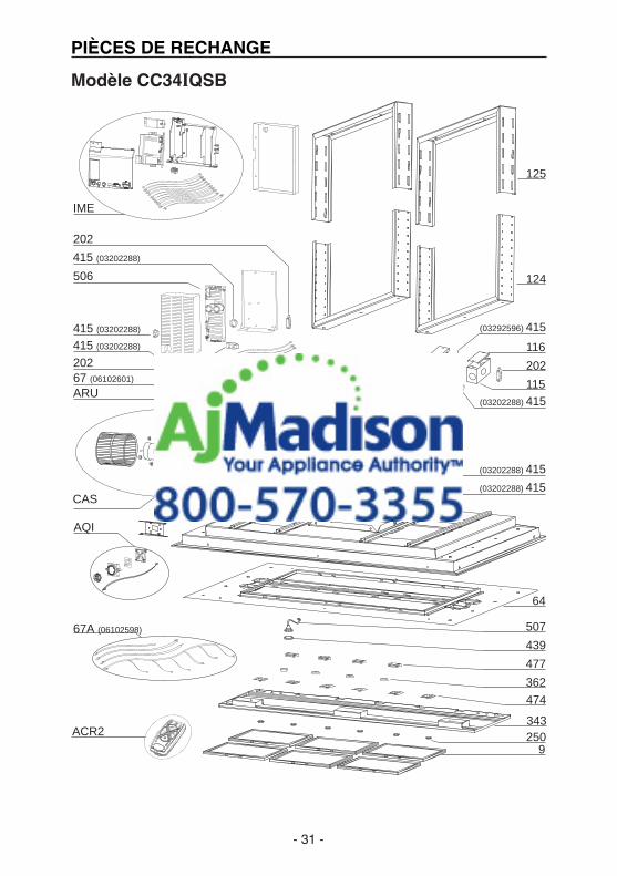
PIÈCES DE RECHANGE
REPÈRE DESCRIPTION N° DE PIÈCE.
CAS ENSEMBLE DE VENTILATEU 06002259 506 CIRCUIT DE MOTEUR C.C. SANS BALAIS 97019431 67 FILS 06102601 202 ATTACHE DE CÂBLE 03292290 415 GUIDE-CÂBLE 03202288 IME ENSEMBLE D’INSTALLATION ÉLECTRIQUE 06145222 67A FILS 06102598 115 BOÎTIER DE CONNEXION
DU CÂBLE D’ALIMENTATION E3350233 415 GUIDE-CÂBLE 03292596 116 COUVERCLE DU BOÎTIER DE CONNEXION
DU CÂBLE D’ALIMENTATION E3351530 125 SUPPORT TÉLESCOPIQUE SUPÉRIEUR 08092797 124 SUPPORT TÉLESCOPIQUE INFÉRIEUR E3404965 64 SUPPORT INFÉRIEUR 03115251 507 ENSEMBLE DE BOUTON DE CALIBRAGE 06102584 439 BAGUE ISOLANTE 02320034 474 VOYANT DEL 02300885 250 ANNEAU DE FIXATION 02011389 AQI ENSEMBLE DE BOÎTIER D’INTERRUPTEUR 06102585 343 PANNEAU D’OBTURATION 08093076 477 CHARNIÈRE 02011376 362 RESSORT DE VISIÈRE D’AFFICHAGE 02011421 9 FILTRE À GRAISSES 08087804 ARU ENSEMBLE DE RACCORD DE SORTIE D’AIR 08092501 ACR2 TÉLÉCOMMANDE 08999166 QUINCAILLERIE 080810994 DIRECTIVES D’INSTALLATION 080813623
Modèle CC34IQSB
- 31 -
PIÈCES DE RECHANGE
Modèle CC34IQSB
CAS
125
124
474
477
343
2509
AQI
IME
US-CIRRUS BLDC
64
362
439
507
506
202
ARU
202
116
202
115
415 (03202288)
415 (03202288)
415 (03202288)
(03292596) 415
(03202288) 415
(03202288) 415
(03202288) 415
ACR2
67 (06102601)
67A (06102598)

- 32 -99045156C
GARANTIE
Garantie limitée Période de garantie et exclusions : Broan-NuTone LLC (la « Société ») garantit au consommateur acheteur initial (« vous ») de son produit (le « Produit ») que celui-ci est exempt de tout vice de matériau ou de fabrication pour une période de un (1) an à compter de la date d’achat originale.La période de la garantie limitée sur toute pièce de remplacement fournie par la Société et sur tout produit réparé ou remplacé en vertu de la présente garantie limitée correspond au reste de la période de garantie originale.Cette garantie ne s’applique pas aux tubes fluorescents et aux démarreurs de tubes fluorescents, ni aux ampoules halogènes ou incandescentes, fusibles, filtres, conduits, capuchons de toit, capuchons muraux et autres accessoires pour conduits pouvant avoir été achetés séparément et installés avec le produit. La présente garantie ne couvre pas (a) les travaux d’entretien et de service normaux, (b) l’usure normale, (c) tout produit ou toute pièce ayant fait l’objet d’une mauvaise utilisation, d’un abus, d’un usage anormal, d’une négligence, d’un accident, d’un entretien, d’un rangement ou d’une réparation inadéquats ou insuffisants (autre que par la Société), (d) les dommages dus à une mauvaise installation, ou à une installation ou utilisation contraires aux recommandations ou instructions, (e) tout produit déplacé de son lieu d’installation original, (f) les dommages dus à des éléments environnementaux ou naturels, (g) les dommages dus au transport, (h) l’usure naturelle du fini, (i) les produits utilisés à des fins commerciales ou non-résidentielles ou (j) les dommages dus à un incendie, à une inondation ou à un événement fortuit. Cette garantie ne couvre que les produits vendus au consommateur initial aux États-Unis par la Société ou par les distributeurs américains autorisés par la Société. La présente garantie remplace toute garantie précédente et le consommateur et acheteur initial ne peut la céder à quiconque. Aucune autre garantie : Cette garantie limitée stipule les seules obligations de la Société et votre seul recours en cas de produits défectueux. La garantie ci-dessus est exclusive et remplace toute autre garantie, expresse ou tacite. LA SOCIÉTÉ EXCLUT TOUTE AUTRE GARANTIE EXPRESSE ET TOUTE GARANTIE DÉCOULANT IMPLICITEMENT DE LA LOI, Y COMPRIS, SANS S’Y LIMITER, LES GARANTIES DE VALEUR MARCHANDE ET D’ADÉQUATION À UN USAGE PARTICULIER. Dans la mesure où la loi en vigueur interdit l’exclusion des garanties tacites, la durée de toute garantie tacite est limitée à la période stipulée ci-dessus pour la garantie expresse. Certaines juridictions interdisant de limiter la durée d’une garantie tacite, la limitation ci-dessus peut ne pas s’appliquer à votre situation. Toute description verbale ou écrite du produit a pour seule fin de l’identifier et ne doit pas être interprétée comme une garantie expresse.Si possible, chaque disposition de cette garantie limitée doit être interprétée de sorte à être en vigueur et valide en vertu des lois applicables, mais si une disposition s’avère interdite ou invalide, elle le sera seulement dans la mesure de cette interdiction ou invalidité, sans invalider le reste de cette disposition ni les autres dispositions de la présente garantie limitée.Recours : Pendant la période de garantie limitée applicable, la Société pourra, à son choix, fournir des pièces de rechange ou réparer ou remplacer, sans frais, tout produit ou toute pièce, dans la mesure où la Société constate qu’il est couvert et contrevient à la présente garantie limitée dans des conditions normales d’utilisation et de service. La Société vous enverra gratuitement le produit réparé ou remplacé ou les pièces de rechange. Vous êtes responsable des frais de démontage, de remontage, d’expédition, d’assurance ou de tous autres frais de transport pour l’envoi du produit ou de la pièce à la Société. Si vous devez envoyer le produit ou la pièce à la Société, tel que la Société vous l’indiquera, vous devrez l’emballer correctement – la Société n’est pas responsable des dommages subis lors du transport. La Société se réserve le droit d’utiliser des produits ou des pièces remis en état, remis à neuf, réparés ou réusinés dans le processus de réparation ou de remplacement sous garantie. Lesdits produits ou pièces seront comparables en fonction et en performance aux produits et pièces d’origine et seront garantis pendant le reste de la période de garantie originale. Exclusion de dommages : L’OBLIGATION DE LA SOCIÉTÉ DE FOURNIR DES PIÈCES DE RECHANGE, OU DE RÉPARER OU REMPLACER LE PRODUIT, À SON CHOIX, CONSTITUE VOTRE SEUL ET UNIQUE RECOURS EN VERTU DE LA PRÉSENTE GARANTIE LIMITÉE ET LA SEULE ET UNIQUE OBLIGATION DE LA SOCIÉTÉ. LA SOCIÉTÉ NE PEUT ÊTRE TENUE RESPONSABLE DE TOUT DOMMAGE INDIRECT, CONSÉCUTIF, ACCESSOIRE OU SPÉCIAL DÉCOULANT DE L’UTILISATION OU DU RENDEMENT DU PRODUIT. Certains territoires ou provinces ne permettant pas la limitation ou l’exclusion des dommages indirects ou consécutifs, la limitation ci-dessus peut ne pas s’appliquer à votre situation. La présente garantie vous confère des droits spécifiques reconnus par la loi. D’autres droits pourraient également vous être accordés selon la législation locale en vigueur. Cette garantie ne couvre que le remplacement ou la réparation des produits ou pièces défectueux à l’usine principale de la Société et ne comprend pas les frais de voyage et ni les dépenses quotidiennes pour une réparation à domicile.Toute aide que la Société vous fournit en dehors des dispositions, limitations ou exclusions de cette garantie limitée ne constituera en rien une renonciation auxdites dispositions, limitations ou exclusions, et ne prolongera aucunement cette garantie pas plus qu’elle ne la remettra en vigueur.La Société ne vous remboursera aucune dépense encourue par vous pour la réparation ou le remplacement de tout produit défectueux, sauf celles que vous avez encourues avec la permission écrite préalable de la Société.Comment bénéficier du service de garantie : Pour vous prévaloir de cette garantie, vous devez (a) aviser la Société à l’adresse ou au numéro de téléphone indiqués ci-dessous dans les sept (7) jours du constat de la défectuosité couverte, (b) donner le numéro de modèle du produit et le numéro d’identification de la pièce et (c) décrire la nature de la défectuosité du produit ou de la pièce. Lors de votre demande de garantie, vous devez présenter une preuve de la date d’achat originale. Si vous ne pouvez pas fournir une copie écrite de la garantie limitée originale, les dispositions de la garantie limitée écrite la plus récente de la Société concernant ce produit particulier s’appliqueront. Vous trouverez les garanties limitées écrites les plus récentes des produits de la Société sur le site www.BestRangeHoods.com.Aux États-Unis – BEST® Hartford, Wisconsin 800-558-1711 Au Canada – BEST® Drummondville, QC 866-737-7770 www.BestRangeHoods.com

- 33 -
Modelo CC34IQSBENGLISH.....................................2FRANÇAIS.................................17ESPAÑOL.................................. 33
En EE. UU. - BEST Hartford, Wisconsin En CANADÁ - BEST Drummondville, QC, Canadá
REGISTRE SU PRODUCTO EN LÍNEA EN: www.BestRangeHoods.com/registerSi desea información adicional, visite www.BestRangeHoods.com

- 34 -
LEA Y CONSERVE ESTAS INSTRUCCIONES
ADVERTENCIAPARA REDUCIR EL RIESGO DE INCENDIOS, DESCARGAS ELÉCTRICAS O LESIONES PERSONALES, SIGA LAS SIGUIENTES PRECAUCIONES:1. Use la unidad solo de la manera indicada por el fabricante. Si tiene preguntas, comuníquese
con el fabricante a la dirección o al número telefónico que se incluye en la garantía.
2. Antes de dar servicio o limpiar la unidad, interrumpa el suministro eléctrico en el panel de servicio y bloquee el panel de servicio para evitar que se active accidentalmente la electricidad. Cuando no sea posible bloquear los medios de desconexión del servicio, fije firmemente una señal de advertencia (como una etiqueta) en un lugar visible del panel de servicio.
3. El trabajo de instalación y el cableado eléctrico deben estar a cargo de personal capacitado, de acuerdo con todos los códigos y normas correspondientes, incluidos los códigos y normas de construcción específicos sobre protección contra incendios.
4. Es necesario suficiente aire para que se lleve a cabo una combustión y una extracción adecuadas de los gases a través del tubo de humos (chimenea) del equipo quemador de combustible, con el fin de evitar el contratiro. Siga las directrices y las normas de seguridad del fabricante del equipo de calefacción, como las publicadas por la Asociación Nacional de Protección contra Incendios (National Fire Protection Association, NFPA), y la Sociedad Americana de Ingenieros en Calefacción, Refrigeración y Aire Acondicionado (American Society for Heating, Refrigeration and Air Conditioning Engineers, ASHRAE), y las autoridades de los códigos locales.
5. Al cortar o perforar a través de la pared o del cielo raso, tenga cuidado de no dañar el cableado eléctrico ni otros servicios ocultos.
6. Los ventiladores con conductos siempre deben ventearse hacia el exterior.
7. No use esta unidad junto con ningún dispositivo separado de estado sólido para el control de la velocidad.
8. Para reducir el riesgo de incendio, use solamente conductos metálicos.
9. Esta unidad debe estar conectada a tierra.
10. Instalación del tipo que no es IC: El aislamiento térmico no debe cubrir la cubierta superior de la campana y debe estar separado 3 pulgadas (76 mm) de todos los lados. (Fig. 1)
! INDICADO SOLAMENTE PARA COCINAR EN CASA !
MÍNIMO DE 3 PULG. (76 MM). SIN AISLAMIENTO DENTRO DE ESTA ZONA SOMBREADA DE
COMPONENTES
FIG. 1

- 35 -
! PRECAUCIÓN1. Solo debe usarse bajo techo.
2. Para reducir el riesgo de incendio y para descargar adecuadamente el aire, asegúrese de dirigir el aire hacia el exterior. No descargue el aire en espacios contenidos entre paredes o cielos rasos, ni en áticos, sótanos bajos ni en la cochera.
3. Tenga cuidado cuando use agentes de limpieza o detergentes.
4. Evite usar bajo la campana de la estufa productos alimenticios que produzcan llamas.
5. Solo para usarse como medio de ventilación general. No debe usarse para la extracción de materiales o vapores peligrosos o explosivos.
6. Para evitar daños a los cojinetes del motor y rotores ruidosos o desbalanceados, mantenga la unidad de potencia protegida contra rociados de yeso, polvos de construcción, etc.
7. Este motor de campana tiene una protección contra sobrecargas térmicas que automáticamente apagará el motor en caso de sobrecalentamiento. El motor reanudará su funcionamiento cuando se enfríe. Si el motor continúa apagándose y encendiéndose, solicite servicio para la campana.
8. Para capturar mejor las impurezas producidas al cocinar, la parte inferior de la campana debe estar a una altura mínima de 48 pulg. (122 cm) y máxima de 72 pulg. (183 cm) sobre la superficie de cocinado. Consulte el apartado “Instalación del soporte de montaje” para ver las restricciones de montaje.
9. Se recomienda que dos personas hagan la instalación debido al gran tamaño y peso de esta campana.
10. La fuente de luz está diseñada para esta aplicación específica y puede sobrecalentarse si recibe servicio de personal no capacitado. Si se requiere algún servicio, debe regresar el producto a un centro de servicio autorizado para que lo examinen o reparen.
11. Lea la etiqueta de especificaciones del producto para ver información y requisitos adicionales.
PARA REDUCIR EL RIESGO DE INCENDIO PROVOCADO POR GRASA PRESENTE EN LA ESTUFA:
A. Nunca deje desatendidas las unidades de la superficie cuando estén en ajustes altos de calor. Los alimentos en ebullición provocan derrames grasosos y con humo que se pueden incendiar. Caliente el aceite lentamente en ajustes de calor bajo o medio.
B. Siempre ENCIENDA la campana cuando esté cocinando a altas temperaturas o flamee alimentos (por ejemplo crepas Suzette, cerezas Jubilee, bistec con pimienta flameado).
C. Limpie frecuentemente los ventiladores. No permita la acumulación de grasa en el ventilador ni en el filtro.
D. Use una cacerola del tamaño adecuado. Siempre use utensilios de cocina que sean apropiados para el tamaño del elemento de la superficie.
PARA REDUCIR EL RIESGO DE LESIONES A LAS PERSONAS EN CASO DE UN INCENDIO PRODUCIDO POR GRASA EN UNA ESTUFA, OBSERVE LO SIGUIENTE*:
1. APAGUE LAS LLAMAS con una tapa de ajuste exacto, una charola para galletas o una bandeja de metal, y después apague el quemador. PROCEDA CON CUIDADO PARA EVITAR QUEMADURAS. Si las llamas no se apagan inmediatamente, EVACUE EL ÁREA Y LLAME A LOS BOMBEROS.
2. NUNCA LEVANTE UNA CACEROLA INCENDIADA porque podría ocasionarse quemaduras.3. NO TRATE DE APAGAR EL FUEGO CON AGUA ni con trapos o toallas de cocina mojados,
pues ocasionará una explosión violenta de vapor.4. Use un extintor SOLO si:
A. El extintor es de Clase ABC y usted sabe cómo hacerlo funcionar.B. El incendio es pequeño y está confinado al área en la que se inició.C. Se está llamando al Departamento de Bomberos.D. Puede combatir el incendio teniendo la espalda orientada hacia una salida.
* Basado en “Kitchen Fire Safety Tips” (Sugerencias para la seguridad contra incendios en la cocina)

- 36 -
FUNCIONAMIENTO
Controles (Fig. 2)La campana se opera mediante los (5) botones pulsadores que se encuentran en la campana y en el control remoto. Los colores de los LED se muestran solamente en el control de la campana.
FIG. 2
(P1) Interruptor de retraso• Sucampanaincluyeuninterruptorderetrasodelventiladorde10minutos.Presioneunavezeste
interruptor para activar el contador de tiempo y que el anillo de LED (L1) destelle en color azul. El ventilador seguirá funcionando 10 minutos. Después de 10 minutos, el ventilador se apaga automáticamente.
• Paracancelarelretardode10minutos,presionedenuevoelinterruptorderetardo.(P2) Interruptor de la alarma del filtro• Despuésde30horasdefuncionamientodelventilador,seactivalaalarmadelfiltroyelanillo
de LED (L1) se enciende en color rojo/destella. Indica que es necesario limpiar los filtros de grasa.• Despuésde limpiar los filtrosdegrasa, reinicieel contadordehoraspresionandoelbotón
de alarma del filtro/reinicio del contador (P2) mientras se visualiza la alarma.(P3) Interruptor para reducir la velocidad del ventilador y apagarlo • Presioneparareducirlavelocidaddelventilador,dealtaabaja.ElanillodeLED(L1)destella
en color azul a una velocidad proporcional al ajuste del ventilador (es decir: cuatro destellos es alta velocidad, un destello es baja velocidad, etc.)
• Sigapresionandoesteinterruptorparaapagarelventilador.(P4) Interruptor para aumentar la velocidad del ventilador y encenderlo• Presioneesteinterruptorparaencenderelventiladorabajavelocidad.• Presiónelootravezparaaumentarlavelocidaddelventilador,debajaaalta.ElanillodeLED
(L1) destella en color azul a una velocidad proporcional al ajuste del ventilador (es decir: cuatro destellos es alta velocidad, un destello es baja velocidad, etc.)
(P5) Interruptor de lucesEnciende y apaga las luces.
P1
P2
P3 P4
ANILLO DE LED L1
P5+-
ƒ
¤
P1: Retraso para activar/desactivar (10 minutos) P2: Reinicio de contador de tiempo de indicación de cambio de filtro P3: Reduce la velocidad del motor del ventilador hasta que se
apaga (4>3>2>1>APAGADO) P4: Enciende el motor del ventilador y aumenta la velocidad
(ENCENDIDO>1>2>3>4) P5: Enciende/apaga las luces L1: Corona de señalización del anillo indicador de LED: - Campana en espera: se enciende color verde.
30 segundos después de que se ha presionado la última tecla se apaga el centro.
- Motor encendido: L1 enciende en color azul destellando. La frecuencia de destello es proporcional a ajuste a la velocidad.
- Función de TEMPORIZADOR de 10 minutos: L1 enciende y parpadea en azul.
- Alarma del filtro activa: L1 enciende en color rojo.
Función de apagado automático
Si el ventilador y/o las luces están encendidas continuamente 10 horas sin que el usuario interactúe con los controles, la campana se apagará automáticamente. Presione calquier botón de control para reactivar la campana.

- 37 -
CONTROL DE LA CAMPANA
CONTROL REMOTO
El control remoto se enlaza a la campana en la fábrica.
Si por alguna razón se pierde el enlace, siga estas instrucciones:
Para enlazar el control remoto a la campana
1. Apague el motor y las luces de la campana.
2. Presione
en el control remoto por lo menos 3 segundos. La luz indicadora se encenderá. (Fig. 3)
3. Mientras sostiene
en el control remoto, presione ƒ (P2) en el control de la campana. (Fig. 4) El anillo de LED encenderá en color VERDE aproximadamente 10 segundos para confirmar que el proceso de enlace fue exitoso.
P1
P2
P3 P4
ANILLO DE LED L1
P5+-
ƒ
¤
P1: Retraso para activar/desactivar (10 minutos) P2: Reinicio de contador de tiempo de indicación de cambio de filtro P3: Reduce la velocidad del motor del ventilador hasta que se
apaga (4>3>2>1>APAGADO) P4: Enciende el motor del ventilador y aumenta la velocidad
(ENCENDIDO>1>2>3>4) P5: Enciende/apaga las luces L1: Corona de señalización del anillo indicador de LED: - Campana en espera: se enciende color verde.
30 segundos después de que se ha presionado la última tecla se apaga el centro.
- Motor encendido: L1 enciende en color azul destellando. La frecuencia de destello es proporcional a ajuste a la velocidad.
- Función de TEMPORIZADOR de 10 minutos: L1 enciende y parpadea en azul.
- Alarma del filtro activa: L1 enciende en color rojo.
LUZ INDICADORA
FIG. 4FIG. 3
P1
P2
P3 P4
P5
- 23A
+
P1
P2
P4
P3
HOODP1: 5' TIMER function activation/deactivation.
hood sensor: AUTOMATIC function activation/deactivation.
P2: Motor off/motor speed decrease.P3: Motor on/motor speed increase.P4: Lights on/off.
As soon as the button ispressed, the circular crownlights up for 1".
Desecho de la pilaCuando sea necesario cambiar las pilas, deséchelas únicamente en los recipientes especiales para desecho que encuentra fácil y en gran cantidad, en especial en tiendas que venden productos electrónicos de consumo. El cumplimiento de los reglamentos sobre recolección diferenciada de residuos y, en particular, la disposición adecuada de pilas usadas, contribuye a prevenir posibles efectos negativos sobre el medio ambiente y la salud.
LINKING procedure- To unambiguously associate the radio control with
the hood, you can activate a LINKING procedure.Once the procedure has terminated, the radiocontrol functions only and exclusively with theassociated product.
- This procedure is useful if there are two or moreproducts that can be controlled by means of radiocontrol, for example, in apartments with adjacentkitchens, showrooms, fairs, etc.
1 - Turn off the hood motor and the lights2 - Press P1 for 3": the circular crown will light up3 - Confirm the link to the hood within 3" by pressing
the button indicated on the next page.
Confirm P2
PRECAUCIÓN RIESGO DE EXPLOSIÓN SI SE REEMPLAZA LA PILA CON UNA DEL TIPO INCORRECTO. DESECHE LA PILA USADA SEGÚN LAS INSTRUCCIONES.
Funciones del control remoto (Fig. 3)
Retraso – Apagado
Se reduce la velocidad del ventilador y se apaga
Se aumenta la velocidad del ventilador y se enciende
Luz
P1
P2
P3 P4
P5
- 23A
+
P1
P2
P4
P3
HOODP1: 5' TIMER function activation/deactivation.
hood sensor: AUTOMATIC function activation/deactivation.
P2: Motor off/motor speed decrease.P3: Motor on/motor speed increase.P4: Lights on/off.
As soon as the button ispressed, the circular crownlights up for 1".
Battery disposalWhen the batteries need to be replaced, dispose of them only and exclusively in the numerous readily availablespecial waste bins, especially in shops selling electronic consumer goods. Observance of the regulations ondifferentiated waste collection, in particular, proper disposal of used batteries, contributes to preventing possiblenegative effects on the environment and health.
LINKING procedure- To unambiguously associate the radio control with
the hood, you can activate a LINKING procedure.Once the procedure has terminated, the radiocontrol functions only and exclusively with theassociated product.
- This procedure is useful if there are two or moreproducts that can be controlled by means of radiocontrol, for example, in apartments with adjacentkitchens, showrooms, fairs, etc.
1 - Turn off the hood motor and the lights2 - Press P1 for 3": the circular crown will light up3 - Confirm the link to the hood within 3" by pressing
the button indicated on the next page.
Confirm P2
CAUTION RISK OF EXPLOSION IF BATTERY ISREPLACED BY AN INCORRECT TYPE. DISPOSEOF USED BATTE TO THE INSTRUCTION.
Nota: reajuste del filtro no es posible con el mando a distancia.
Si desea más información sobre cada función, vea la sección “Controles” en la página anterior.

- 38 -
LIMPIEZA Y MANTENIMIENTOEl mantenimiento correcto de la campana de la estufa asegurará el funcionamiento adecuado de la unidad.
MotorEl motor está permanentemente lubricado y nunca necesitará ponerle aceite. Si los cojinetes del motor están haciendo ruido excesivo o inusual, reemplace el motor con el motor de servicio exacto. También debe reemplazar el impulsor.
Filtros de grasaLos filtros de grasa se deben limpiar con frecuencia con una solución tibia de detergente y agua. Los filtros de grasa se pueden lavar en lavaplatos.
Limpie los filtros completamente metálicos en el lavaplatos con un detergente sin fosfatos. El filtro se puede decolorar si se utilizan detergentes con fosfatos o como resultado de la condición del agua local, pero esto no afectará el desempeño del filtro. Esta decoloración no está cubierta por la garantía.Consulte la sección “INSTALACIÓN DE LOS FILTROS” para ver las instrucciones de instalación y desmontaje.
Limpieza del acero inoxidable
COSAS QUE PUEDE HACER:• Regularmente,laveconunatelaotrapolimpio
remojado con agua tibia y jabón o detergente líquido para platos.
• Siempre limpieen ladirecciónde las líneasoriginales de pulido.
• Siempre enjuague bien con agua limpia (2 o 3 veces) después de la limpieza. Séquelo por completo.
• También puede usar un limpiador caseroespecializado para acero inoxidable.
COSAS QUE NO DEBE HACER:
• Usar lana de acero o acero inoxidable ni algún otro tipo de raspador para quitar mugre difícil de sacar.
• Usarlimpiadoresfuertesniabrasivos.
• Dejarqueseacumulelamugre.
• Dejar que el polvo forme plastas ni quequede en la campana algún otro residuo de la construcción. Durante la construcción o la renovación, cubra la campana para estar seguro de que el polvo no se pegue a la superficie de acero inoxidable.
Evite: Al elegir un detergente• Todolimpiadorquecontengablanqueador,puesatacaráalaceroinoxidable.• Todoproductoquecontenga:cloruro,fluoruro,yoduro,bromuro,puesdeteriorarálassuperficies
rápidamente.• Todoproductocombustibleutilizadoparalalimpieza,comoacetona,alcohol,éter,benzol,etc.,pues
son altamente explosivos y nunca se deben usar cerca de una estufa.

- 39 -
PREPARE LA CAMPANADesempaque la campana y revise el contenido del paquete.
Debe contener lo siguiente: 1 - Cuerpo de la campana 1 - Control remoto 6 - Filtros de grasa 2 - Tornillos, 4 x 9.5 mm
6 - Ttornillos para madera, 6 x 70 mm 6 - Arandelas
6 TORNILLOS PARA MADERA, 6 x 70 mm
FIG. 5
CONTROL REMOTO
CUERPO DE LA CAMPANA CON REGULADOR
6 FILTROS DE GRASA
6 ARANDELAS
2 TORNILLOS (4 x 9.5 mm)

- 40 -
INSTALACIÓN DEL SISTEMA DE CONDUCTOS
FIG. 6
TAPA DE TECHO
DE 48 A 72 PULG. (122 A 183 CM) POR ENCIMA DE LA SUPERFICIE DE COCINADO
CAMPANA
CONDUCTO REDONDO DE 8 pulg. (20.3 cm)
REDUCTOR DE 8 PULG. (20.3 cm)
REDONDO A 3 ¼ X 14
PULG (8.3 x 35.6 cm)
RESPIRADERO DEBAJO
DEL ALERO DE 3 1/4 X 14
PULG. (8.3 x 35.6 cm)
CONDUCTO REDONDO DE 8 pulg. (20.3 cm)
ADVERTENCIA: Para reducir el riesgo de incendio, use solamente conductos metálicos.
1. Dec ida dónde ins ta la rá el conducto entre la campana y el exterior. Fig. 6.
2. Un conducto recto y corto permitirá que la campana funcione más eficientemente.
3. Los tramos largos de conductos, codos y transiciones reducirán el rendimiento de la campana. Use tan pocos de ellos como sea posible. Es posible que se requ ie ran conduc tos más grandes para un mejor funcionamiento con tramos más largos de conductos.
4. Instale una tapa de techo, una tapa de pared o un respiradero debajo del alero. Conecte un conducto metálico redondo en la tapa/respiradero y trabaje hacia atrás, hacia la ubicación de la campana. Use cinta para conductos para sellar las uniones entre las secciones de conductos.
5. El ventilador se puede girar de acuerdo con la ubicación de la salida de aire. Consulte las dimensiones de la salida de aire en la Figura 7.
8 ¾ pulg. (22.2 cm)
13 ¾ (34.9 cm)
8 ¾ pulg. (22.2 cm)
21 11/16 pulg. (55.1 cm)
FIG. 7
- O BIEN -
UBICACIÓN DE LA SALIDA DE LA CAMPANA

- 41 -
PREPARE EL SOPORTE DE LA CAMPANA1. Construya un sistema de marco de madera
como se muestra en la Figura 9.
2. La estructura debe poder soportar su propio peso, más el peso de la campana (64 libras / 29 kg).
FIG. 9
MARCO DE2 x 4
37-1/4 pulg.(94.6 cm)
42-1/2 pulg.(107.9 cm)
14 pulg.(35.5 cm)
26-3/4 pulg.(67.9 cm)
2-5/8 pulg.(6.66 cm)
11 pulg.(27.9 cm)
11 pulg.(27.9 cm)
ORIFICIOPILOTO DE1/8 pulg. (6)
11 pulg.(27.9 cm)
11 pulg.(27.9 cm)
ORIFICIOPILOTO DE1/8 pulg. (6)
PREPARE LA ABERTURA DEL CIELO RASOLa campana siempre debe centrarse por encima de la estufa. Asegúrese de tener espacio adecuado en la estructura del cielo raso para instalar la campana y los conductos. La campana debe montarse de 48 a 72 pulg. (122 a 183 cm) por encima de la estufa para poder eliminar mejor las impurezas al cocinar. Fig. 6
Use madera del tamaño de la viga para enmarcar alrededor de la abertura de la campana. La estructura del cielo raso debe poder sopor tar el peso de la campana (64 libras / 29 kg). Fig. 8.
FIG. 8
mín. 13-3/4 pulg. (33.6 cm)
máx. 22-1/4 pulg. (56.5 cm)
DOBLES CABEZALES
42 ½ pulg.
(108 cm)
26 ¾ pulg. (67.9 cm)

- 42 -
FIJE LA CAJA DE CONTROL
1. Retire la caja de control de un lado de la caja del ventilador. Fig. 10.
2. Inserte la caja de control en la abertura. Fig. 11.
3. Fije la caja de control con (2) tornillos 4 x 9.5 mm suministrados. Fig. 12.
FIG. 10
FIG. 11
FIG. 12
CAJA DE CONTROL PEGADA CON CINTA A LA CUBIERTA DEL
VENTILADOR
CAJA DE CONTROL
ABERTURA EN LA CAMPANA
FIJE LOS TORNILLOS POR EL LADO DEL FILTRO
(2) TORNILLOS DE 4 X 9.5 mm

- 43 -
INSTALACIÓN DE LA CAMPANA
PRECAUCIÓN: Se recomienda que por lo menos dos personas hagan la instalación debido al gran tamaño y peso de esta campana.
1. La campana se envía en posición de descarga de conducto horizontal y está lista para instalarse.
2. Para cambiar la dirección del conducto sin usar codos. Fig. 13:
• Retire(2)tornillosdelinteriordelacajadel ventilador.
• Retire(4)tornillosdelosladosdelacajadel ventilador.
• Retire el ventilador, gírelo 90 grados y reinstale (4) tornillos.
3. Levante la campana hacia la abertura del cielo raso.
4. Asegure cada marco de soporte con el marco de soporte de madera de la campana con los (6) tornillos para madera de 6 x 70 mm y las arandelas suministradas. Fig 14.
5. Ajuste la altura del marco de soporte telescópico para garantizar un ajuste apretado entre la campana y el cielo raso terminado.
6. En el collarín de descarga del ventilador, conecte el conducto que extrae el aire hacia la descarga exterior.
7. Pegue con cinta todas las uniones para garantizar un sello de aire hermético.
FIG. 13
TORNILLOS (4)
FIG. 14
MARCO DE MADERA 2 X 4
(6) ARANDELAS Y TORNILLOS
PARA MADERA
CONECTE EL CABLEADO
ADVERTENCIA: Una o más personas calificadas deben realizar el trabajo de cableado eléctrico, de acuerdo con todos los códigos y las normas correspondientes. Esta campana debe estar adecuadamente conectada a tierra.
No encienda el ventilador en el panel de servicio antes de conectar todos los cables.
1. Pase el cable eléctrico de 2 alambres y tierra de 120 VCA por el agujero ciego de ¾ pulg. (19 mm) que se encuentra en la parte posterior de la campana. Fig. 15.
2. Ret i re el agujero ciego eléctr ico de ¾ pulg. (19 mm) de la parte posterior de la campana.
FIG. 15
ENTRADA DE LÍNEA
DE 120 VCA, 2 ALAMBRES
Y TIERRA
AGUJERO CIEGO

- 44 -
CONECTE BLANCO CON BLANCO, NEGRO CON NEGRO Y VERDE CON TIERRA.
FIG. 16
FIG. 17
LÍNEA DE ENTRADA DE 120 VCA
CAJA MARCADA
“ENTRADA DE 120 VCA”
3. Desde el interior de la habitación, estire hacia abajo los dos paneles de cierre. Fig. 16.
4. Retire (4) tornillos del panel de acceso del compartimiento eléctrico. Deslice el panel hacia un lado para exponer la caja de conexiones eléctricas.
5. Desde la caja eléctr ica marcada “entrada de 120 VCA”, retire (2) tornillos que aseguran la cubier ta a la caja de conexiones metálica. Fig. 17.
6. Estire el cable eléctrico de 120 VCA hacia la caja y asegure con una abrazadera de cable adecuada.
7. Haga las conexiones eléctricas dentro de la caja. Conecte blanco con blanco, negro con negro y verde con tierra.
8. Vuelva a colocar la cubierta de la caja de conexiones y los tornillos. Asegúrese de que los cables no queden atrapados entre la cubierta y la caja.
9. Regrese a su lugar el panel de acceso para compar t imientos e léct r icos y (4) tornillos.
REGULADOR DE AIRE DE REPUESTO
La campana es compatible con el regulador de aire de repuesto Broan, Modelo MD6T, Modelo MD8T o Modelo MD10T (opcional). Se compra por separado.
Realice la conexión del regulador de aire de repuesto con cableado de bajo voltaje, como se ilustra. Consulte información adicional en las instrucciones del regulador de aire de repuesto. (Fig. 18)
REGULADOR DE AIRE DE REPUESTO
CAMPANA
TRANSFORMADOR DE 24 V
(INCLUIDO)
TIERRA
CAJA DE CONEXIONES
PARA LA CONEXIÓN DEL BAJO VOLTAJE
CONEXIÓN DEL REGULADOR DE REPUESTO(conmutado en bajo voltaje)
CABLE DEL TIMBRE CALIBRE 20 PARA CONEXIÓN DE BAJO VOLTAJE EN LA PARTE SUPERIOR DE LA CAMPANA
120 VCA60 HZ
FIG. 18

- 45 -
INSTALE LOS FILTROS1. Estire hacia abajo los dos paneles
de cierre como se ilustra. Fig. 19 y Fig. 20.
2. Para instalar los filtros de grasa, alinee las lengüetas posteriores del filtro con las ranuras de la campana. Empuje hacia abajo la lengüeta de cierre, presione el filtro en su posición y suelte. Asegúrese de que el filtro esté firmemente enganchado después de su instalación.
3. Para quitar los filtros para limpiarlos, em-puje la lengüeta de cierre para desacoplar el filtro de la campana. Incline el filtro hacia abajo y retírelo.
FIG. 19
FIG. 20CALIBRACIÓN DEL VENTILADOR IQ™SOLO UNIDADES CON CONDUCTOS DE VENTILADOR INTERNODespués de instalar y cablear la campana, active el proceso de calibración (nuestra tecnología de sistema de desempeño garantizado, para asegurar que se suministre el flujo de aire nominal total). Antes de la calibración, asegúrese de que todos los filtros y el sistema de conductos estén instalados.
PROCESO DE CALIBRACIÓN Fig. 21.Abra el panel inferior. Sostenga 3 segundos el botón de calibración y este se encenderá. Cierre el panel inferior. El ventilador arrancará y comenzará el proceso de calibración, que tardará aproximadamente 13 minutos. Cuando se termine la calibración, ocurrirá una de dos cosas:
A. El ventilador se apaga y la luz del botón de calibración se apaga = calibración exitosa.
B. El ventilador se apaga y el botón de calibración destella continuamente = Demasiada restricción en los conductos impide que el ventilador IQ™ obtenga el flujo de aire nominal. El ventilador se configura automáticamente en su intensidad máxima.
NOTA: Elementos comunes que provocan restricciones: el alerón del regulador está restringido (regulador de contratiro, tapa de pared, tapa de techo), demasiados codos, tamaño de conducto menor de 80% de salida de la campana, mala transición, uso de
FIG. 21
BOTÓN DE CALIBRACIÓN
LUZ DE CALIBRACIÓN
conductos flexibles y/o conductos aplastados.
Se tienen disponibles dos opciones:1. Presione el botón de calibración para
aceptar el flujo de aire tal cual. El ventilador IQ™ está configurado ahora en su ajuste más alto posible. La luz de calibración destellante se apaga.
2. Corrija la restricción del conducto y repita el proceso de calibración.a. Para despejar los datos de calibración
originales, sostenga el botó de calibración 10 segundos. La luz destellará 3 veces para confirmar y la configuración del ventilador regresará za los ajustes predeterminados.
b. Repita el proceso de calibración.

- 46 -
PIEZAS DE SERVICIO
CLAVE N.º DESCRIPCIÓN N.º DE PIEZA.
CAS CONJUNTO DE VENTILADOR 06002259 506 CONTROLADOR BLDC 97019431 67 CABLES 06102601 202 ABRAZADERA DE CABLES 03292290 415 BUJE 03202288 IME CONJUNTO DE INSTALACIÓN ELÉCTRICA 06145222 67A CABLES 06102598 115 CAJA DE CONEXIÓN DEL CABLE
DE ALIMENTACIÓN E3350233 415 BUJE 03292596 116 CUBIERTA DE LA CAJA DE CONEXIÓN
DEL CABLE DE ALIMENTACIÓN E3351530 125 ESTRUCTURA TELESCÓPICA SUPERIOR 08092797 124 ESTRUCTURA TELESCÓPICA INFERIOR E3404965 64 SOPORTE INFERIOR 03115251 507 CONJUNTO DEL BOTÓN DE CALIBRACIÓN 06102584 439 JUNTA DE HULE 02320034 474 LUZ LED 02300885 250 TUERCA ANULAR 02011389 AQI CONJUNTO DE LA CAJA DEL INTERRUPTOR 06102585 343 PANEL DE CIERRE 08093076 477 BISAGRA 02011376 362 RESORTE DEL VISOR DE PANTALLA 02011421 9 FILTRO DE GRASA 08087804 ARU JUEGO DE SALIDA DE AIRE DE CONEXIÓN 08092501 ACR2 CONTROL REMOTO 08999166 HERRAJES 080810994 INSTRUCCIONES DE INSTALACIÓN 080813623
Modelo CC34IQSB

- 47 -
PIEZAS DE SERVICIO
Modelo CC34IQSB
CAS
125
124
474
477
343
2509
AQI
IME
US-CIRRUS BLDC
64
362
439
507
506
202
ARU
202
116
202
115
415 (03202288)
415 (03202288)
415 (03202288)
(03292596) 415
(03202288) 415
(03202288) 415
(03202288) 415
ACR2
67 (06102601)
67A (06102598)

- 48 -99045156C
GARANTÍA
Garantía limitadaPeriodo y exclusiones de la garantía: Broan-NuTone LLC (la “Compañía”) garantiza al consumidor comprador original de su producto (“usted”) que el producto (el “Producto”) estará libre de defectos en materiales en el Producto o en la mano de obra, por un periodo de un (1) año a partir de la fecha de la compra original.El periodo de garantía limitada para las piezas de repuesto provisto por la Compañía y para cualquier Producto reparado o reemplazado bajo esta garantía limitada continuará durante el resto del periodo de garantía original.Esta garantía no cubre arrancadores de lámparas fluorescentes, tubos, bombillas de halógeno e incandescentes, fusibles, filtros, conductos, tapas de techo, tapas de pared ni otros accesorios para los conductos que se puedan comprar por separado e instalar con el Producto. Esta garantía tampoco cubre (a) mantenimiento y servicio normal, (b) uso y desgaste normal, (c) Productos o piezas sujetos a mal uso, abuso, uso anormal, negligencia, accidente, mantenimiento inadecuado o insuficiente, almacenamiento o reparación (que no sea reparación por parte de la Compañía), (d) daños causados por instalación defectuosa, o bien instalación o uso contrario a las recomendaciones o instrucciones, (e) cualquier Producto que se haya movido de su punto de instalación original, (f) daños ocasionados por el medio ambiente o los elementos naturales, (g) daños en tránsito, (h) desgaste natural del acabado, (i) Productos en uso comercial o no residencial, o (j) daños ocasionados por incendio, inundación u otro caso fortuito. Esta garantía cubre solamente Productos vendidos a clientes originales en los Estados Unidos por la Compañía o a distribuidores de EE. UU. autorizados por la Compañía. Esta garantía sustituye a todas las garantías anteriores y no es transferible del comprador consumidor original. No hay otras garantías: La Garantía Limitada contiene la única obligación de la Compañía y su recurso exclusivo para productos defectuosos. Las garantías anteriores son exclusivas y están en lugar de cualquier otra garantía, expresa o implícita. LA COMPAÑÍA NIEGA Y EXCLUYE CUALQUIER OTRA GARANTÍA EXPRESA, Y NIEGA Y EXCLUYE TODAS LAS GARANTÍAS IMPLÍCITAS POR LEY, INCLUYENDO, ENTRE OTRAS, LAS DE COMERCIALIZACIÓN Y APTITUD PARA UN PROPÓSITO EN PARTICULAR. Hasta el grado que la ley correspondiente prohíba la exclusión de garantías implícitas, la duración de cualquier garantía implícita aplicable está limitada al periodo especificado para la garantía expresa anterior. Algunos estados no permiten limitaciones en la duración de una garantía implícita, así que la limitación anterior tal vez no aplique en su caso. Cualquier descripción verbal o escrita del Producto es para el único propósito de identificarlo y no deberá considerarse como una garantía expresa.Siempre que sea posible, cada disposición de esta Garantía Limitada deberá interpretarse de tal manera que sea vigente y válida según la ley aplicable pero, si alguna disposición fuera considerada prohibida o inválida, dicha disposición quedará sin efecto únicamente hasta el grado de dicha prohibición o invalidez, sin invalidar el resto de dicha disposición o el resto de las disposiciones de la Garantía Limitada.Recurso: Durante el periodo de garantía limitada aplicable, la Compañía, a su opción, suministrará piezas de repuesto, o reparará o reemplazará, sin cargo alguno, cualquier Producto o pieza del mismo, hasta el grado en que la Compañía lo encuentre cubierto bajo esta garantía limitada y en incumplimiento de la misma en condiciones normales de uso y servicio. La Compañía le enviará el Producto reparado o reemplazado o las piezas de repuesto sin cargo. Usted es responsable de todos los costos de retiro, reinstalación y envío, seguro u otros cargos de flete incurridos en el envío del Producto o pieza a la Compañía. Si debe enviar el Producto o la pieza a la Compañía, tal como lo indique la Compañía, debe empaquetar adecuadamente el Producto o la pieza; la Compañía no se hace responsable por los daños en tránsito. La Compañía se reserva el derecho de utilizar Productos o piezas reacondicionados, renovados, reparados o refabricados en el proceso de reemplazo o reparación de garantía. Dichos Productos y piezas serán comparables en función y desempeño a un Producto o una pieza original y tendrán garantía por el resto del periodo de la garantía original. Exclusión de daños: LA OBLIGACIÓN DE LA COMPAÑÍA DE SUMINISTRAR PIEZAS DE REPUESTO, O DE REPARAR O REEMPLAZAR, A OPCIÓN DE LA COMPAÑÍA, SERÁ SU ÚNICO Y EXCLUSIVO RECURSO BAJO ESTA GARANTÍA LIMITADA, Y LA ÚNICA Y EXCLUSIVA OBLIGACIÓN DE LA COMPAÑÍA. LA COMPAÑÍA NO SERÁ RESPONSABLE POR DAÑOS INCIDENTALES, INDIRECTOS, RESULTANTES O ESPECIALES QUE SURJAN POR EL USO O DESEMPEÑO DEL PRODUCTO, O EN RELACIÓN CON EL MISMO Algunos estados no permiten la exclusión o limitación de daños incidentales o resultantes, por lo que la limitación antes mencionada podría no aplicarse a usted. Esta garantía le otorga derechos legales específicos, y usted podría tener otros derechos que varían de un estado a otro. Esta garantía cubre únicamente el reemplazo o la reparación de Productos o piezas de los mismos con defectos en la planta principal de la Compañía, y no incluye el costo del viaje para el servicio de campo ni los viáticos.Cualquier asistencia que proporcione o procure la Compañía para usted fuera de los términos, limitaciones o exclusiones de esta garantía limitada no constituirá una renuncia a dichos términos, limitaciones o exclusiones, ni dicha asistencia extenderá o renovará la garantía.La Compañía no le reembolsará ningún gasto en el que usted haya incurrido al reparar o reemplazar cualquier Producto defectuoso, excepto los incurridos con el permiso previo por escrito de la Compañía.Cómo obtener el servicio cubierto por la garantía: Para tener derecho al servicio cubierto por la garantía, usted debe (a) notificar a la Compañía a la dirección o número de teléfono que aparecen abajo en un plazo de siete (7) días después de descubrir el defecto cubierto, (b) proporcionar el número de modelo y la identificación de la pieza y (c) describir la naturaleza de cualquier defecto en el Producto o la pieza. En el momento de solicitar el servicio cubierto por la garantía, debe presentar un comprobante de la fecha de compra original. Si no puede presentar una copia de la garantía limitada original por escrito, entonces regirán los términos de la garantía limitada por escrito más actualizada de la Compañía para su producto en particular. Las garantías limitadas por escrito más actualizadas para los productos de la Compañía se pueden encontrar en www.BestRangeHoods.com.En EE. UU. – BEST® Hartford, Wisconsin 800-558-1711 En Canadá - BEST® Drummondville, QC 866-737-7770 www.BestRangeHoods.com


![Treinamento de QSB-Paranoá.ppt [Reparado]](https://img.pdfslide.net/doc/110x75/55cf94bd550346f57ba417a4/treinamento-de-qsb-paranoappt-reparado.jpg)