Embed Size (px)
Citation preview
450 Riverside Dr • Wyalusing PA, 18853 • Phone 570-746-1888 • Fax 570-746-9286AUI-
Member of AMCADivision of Mestek
MODEL EAV-66SD-EAV66-
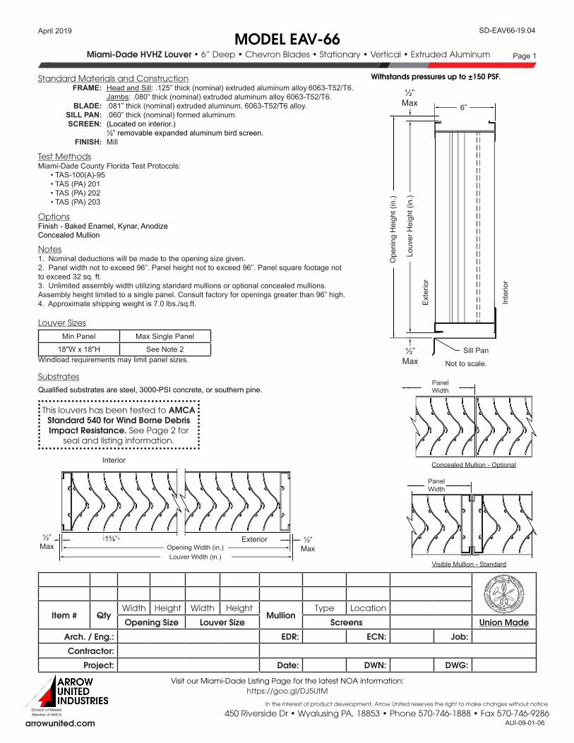
Miami-Dade HVHZ Louver • 6” Deep • Chevron Blades • Stationary • Vertical • Extruded Aluminum Page 1
arrowunited.com
19.04
09-01-06
April 2019
In the interest of product development, Arrow United reserves the right to make changes without notice.
Standard Materials and Construction
Options
Notes
Test Methods
Louver Sizes
Substrates
Item # QtyWidth Height Width Height
MullionType Location
Opening Size Louver Size Screens Union Made
Arch. / Eng.: EDR: ECN: Job:
Contractor:
Project: Date: DWN: DWG:
Min Panel Max Single Panel
18"W x 18"H See Note 2
FRAME: Head and Sill: .125” thick (nominal) extruded aluminum alloy 6063-T52/T6. Jambs: .080” thick (nominal) extruded aluminum alloy 6063-T52/T6. BLADE: .081” thick (nominal) extruded aluminum, 6063-T52/T6 alloy. SILL PAN: .060” thick (nominal) formed aluminum. SCREEN: (Located on interior.) ½” removable expanded aluminum bird screen. FINISH: Mill
Miami-Dade County Florida Test Protocols: • TAS-100(A)-95 • TAS (PA) 201 • TAS (PA) 202 • TAS (PA) 203
Finish - Baked Enamel, Kynar, AnodizeConcealed Mullion
Qualified substrates are steel, 3000-PSI concrete, or southern pine.
1. Nominal deductions will be made to the opening size given.2. Panel width not to exceed 96”. Panel height not to exceed 96”. Panel square footage not to exceed 32 sq. ft. 3. Unlimited assembly width utilizing standard mullions or optional concealed mullions. Assembly height limited to a single panel. Consult factory for openings greater than 96” high.4. Approximate shipping weight is 7.0 lbs./sq.ft.
Windload requirements may limit panel sizes.
Withstands pressures up to ±150 PSF.
Visit our Miami-Dade Listing Page for the latest NOA information:https://goo.gl/DJ5UtM
Ope
ning
Hei
ght (
in.)
Louv
er H
eigh
t (in
.)
½”Max
½”Max
6”
Not to scale.
Exte
rior
Inte
rior
Sill Pan
Panel Width
Concealed Mullion - Optional
Panel Width
Visible Mullion - Standard
Opening Width (in.)Louver Width (in.)
½”Max
½”Max
Exterior
Interior
1⅝”
This louvers has been tested to AMCA Standard 540 for Wind Borne Debris Impact Resistance. See Page 2 for
seal and listing information.

450 Riverside Dr • Wyalusing PA, 18853 • Phone 570-746-1888 • Fax 570-746-9286AUI-
Member of AMCADivision of Mestek
SD-EAV66-MODEL EAV-66
Miami-Dade HVHZ Louver • 6” Deep • Chevron Blades • Stationary • Vertical • Extruded Aluminum Page 2
arrowunited.com
19.04
09-01-06
April 2019
Arrow United Industries certifies that the Model EAV-66 shown herein is licensed to bear the AMCA seal. The ratings shown are based on tests and procedures performed in accordance with AMCA Publication 511 and comply with the requirements of the AMCA Certified Ratings Program. The AMCA Certified Ratings Seal applies to Air Performance and Wind Driven Rain Ratings only.
Arrow United Industries certifies that the Model EAV-66 shown herein is approved to bear the AMCA Listing Label. The ratings shown are based on tests and procedures performed in accordance with AMCA Publications and comply with the requirements of the AMCA Listing Label Program.The AMCA Listing Label applies to Wind Borne Debris Impact Resistant Louvers.
Visit our Miami-Dade Listing Page for the latest NOA information:https://goo.gl/DJ5UtM
Performance Data
Pressure Drop: .164 in. w.g. (40.6 Pa) at 1250 fpm (6.35 m/s) Free Area: 7.85 sq.ft. (0.729 m²) = 49.1% for 48”W x 48”H (1.22m x 1.22m) sample tested in accordance with AMCA Standard 500-L.Missile Impact: “Enhanced Protection” Rated at 55 mph (80 m/s) per ASTM 1886/1996.
Width in. (mm)
18" (457)
24” (610)
36” (914)
48” (1219)
60” (1524)
72” (1829)
84” (2134)
96” (2438)
Hei
ght i
n. (m
m)
18” (457)
0.88 (0.082)
1.22 (0.113)
1.95 (0.181)
2.64 (0.245)
3.38 (0.314)
4.11 (0.381)
4.80 (0.446)
5.55 (0.516)
24” (610)
1.23 (0.114)
1.59 (0.148)
2.61 (0.242)
3.63 (0.337)
4.55 (0.423)
5.56 (0.516)
6.48 (0.602)
7.50 (0.697)
36” (914)
1.93 (0.179)
2.52 (0.234)
4.13 (0.384)
5.74 (0.533)
7.19 (0.668)
8.80 (0.817)
10.25 (0.952)
11.86 (1.102)
48” (1219)
2.63 (0.244)
3.44 (0.320)
5.65 (0.525)
7.85 (0.729)
9.83 (0.913)
12.04 (1.118)
14.02 (1.302)
16.22 (1.507)
60” (1524)
3.33 (0.309)
4.37 (0.406)
7.16 (0.665)
9.96 (0.925)
12.48 (1.159)
15.27 (1.418)
17.79 (1.653)
20.59 (1.913)
72” (1829)
4.03 (0.374)
5.30 (0.492)
8.68 (0.806)
12.07 (1.121)
15.12 (1.405)
18.51 (1.719)
21.56 (2.003)
24.95 (2.318)
84” (2134)
4.73 (0.439)
6.22 (0.578)
10.20 (0.948)
14.18 (1.317)
17.77 (1.651)
21.75 (2.020)
25.33 (2.353)
29.31 (2.723)
96” (2438)
5.43 (0.504)
7.15 (0.664)
11.72 (1.089)
16.29 (1.513)
20.41 (1.896)
24.98 (2.320)
29.11 (2.704)
33.68 (3.129)
Free Area sq.ft. (sq. meters)
Ratings do not include effects of a screen.Test based on 48” x 48” sample size per AMCA Standard 511.
Pres
sure
Dro
p in
. w.g
. (PA
)
Pressure Drop (Intake)
Velocity through Free Area FPM (m/s)
0.01
0.02
0.03
0.05
0.07
0.10
0.20
0.30
0.50
0.70
1.0
(2.5)
(5.0)
(7.4)
(12.4)
(17.4)
(24.8)
(49.6)
(74.4)
(124)
(174)
(248)
200(1.0)
400(2.0)
1000(5.1)
2000(10.2)
10000(50.8)
Intake air converted to standard air density. Tested to AMCA Standard 500-L, Figure 5.5.
Wind-Driven Rain Penetration Classes Discharge Loss Coefficient Classes
Class Effectiveness Class Coefficient
A 100% to 99% 1 0.4 and above
B 98.9% to 95% 2 0.3 to 0.399
C 94.9% to 80% 3 0.2 to 0.299
D Below 80% 4 0.199 and below
Water PenetrationClass
Effectiveness RatioPercentage
Coefficient of DischargeClass
Core VelocityFPM (m/s)
Ventilation AirflowCFM (cm/min)
Free Area VelocityFPM (m/s)
Class A 100.0% Class I 980 (5) 10,546 (299) 2,170 (11)
Water PenetrationClass
Effectiveness RatioPercentage
Coefficient of DischargeClass
Core VelocityFPM (m/s)
Ventilation AirflowCFM (cm/min)
Free Area VelocityFPM (m/s)
Class A 99.2% Class I 784 (4) 8,440 (239) 1,736 (8.8)
Class A 99.1% Class I 877 (4.5) 9,445 (267) 1,943 (9.9)
Class A 99.1% Class I 982 (5) 10,578 (300) 2,176 (11)
Wind driven rain performance tests based on 1 m x 1 m (39.37” x 39.37”) Louver with 7.85 sq.ft. (0.729 m²) free area.
Wind Driven Rain Performance - 29 mph (46.7 kph) with 3 in/h (76 mm/h)
Wind Driven Rain Performance - 50 mph (80.5 kph) with 8 in/h (203 mm/h)

450 Riverside Dr • Wyalusing PA, 18853 • Phone 570-746-1888 • Fax 570-746-9286AUI-
Member of AMCADivision of Mestek
MODEL EAV-66SD-EAV66-
Miami-Dade HVHZ Louver • 6” Deep • Chevron Blades • Stationary • Vertical • Extruded Aluminum Page 3
arrowunited.com
19.04
09-01-06
April 2019
Standard Boxed Frame Louver Model EAV-66
Installation Instructions
Notes1. Mounting angles can be installed with “legs in” or “legs out” for any approved substrate.
2. “Legs out” is the standard construction, “legs in” is optional.
3. The Flanged Sleeve option can be used with any approved substrate.
4. Use shims to obtain uniform clearance between the louver and the louver opening on all sides. Shims are provided by others.
5. Sealant between flanged angle sleeve and the substrate provided by installer.
6. Two mounting angles run the full width of the louver.
Visit our Miami-Dade Listing Page for the latest NOA information:https://goo.gl/DJ5UtM
Backer rod & caulk 3 sides (by others).
Backer rod & caulk 3 sides (by others).
Backer rod & caulk 3 sides (by others).
Do not caulk gap. Do not
caulk gap. Do not caulk gap.
Sill Pan
Sill Pan
Sill Pan
Shim as required(by others).
Shim as required(by others). Shim as required
(by others).
8” Deep Steel Substrate 8” Deep Concrete
Substrate2” x 8” Southern Pine
Substrate
Leg out.
Leg out. Leg in.
0.500” Max. 0.500”
Max.
0.500” Max.
0.500” Max.
0.500” Max. 0.500”
Max.
Standard Boxed Framewith Steel Substrate
Standard Boxed Framewith Concrete Substrate Standard Boxed Frame
with Southern Pine Substrate
450 Riverside Dr • Wyalusing PA, 18853 • Phone 570-746-1888 • Fax 570-746-9286AUI-
Member of AMCADivision of Mestek
SD-EAV66-MODEL EAV-66
Miami-Dade HVHZ Louver • 6” Deep • Chevron Blades • Stationary • Vertical • Extruded Aluminum Page 4
arrowunited.com
19.04
09-01-06
April 2019
Visit our Miami-Dade Listing Page for the latest NOA information:https://goo.gl/DJ5UtM
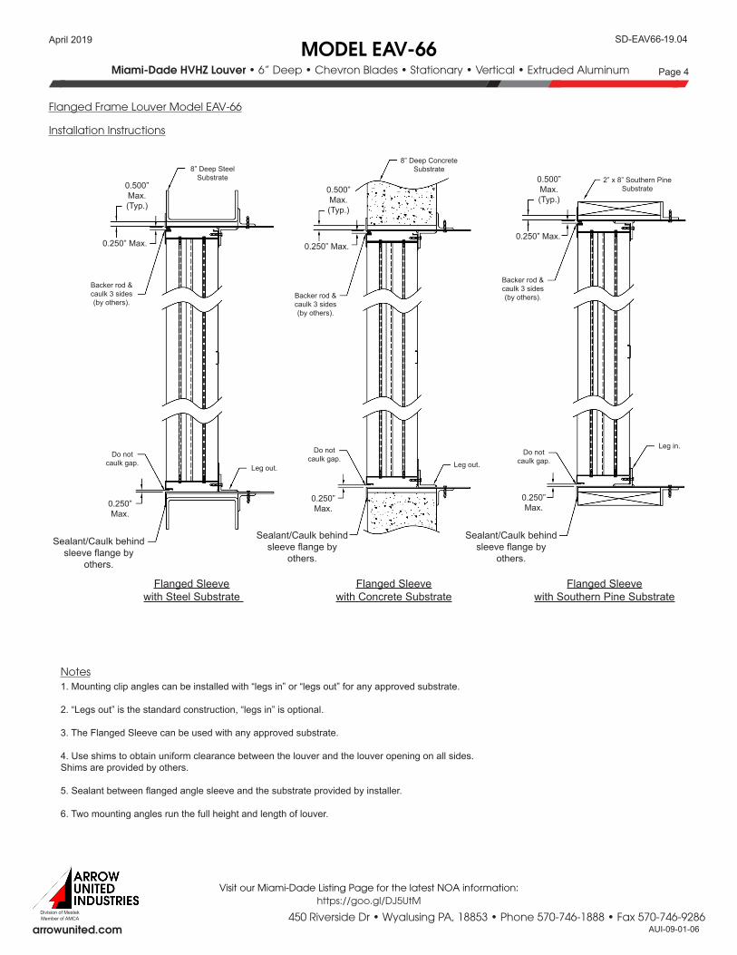
Flanged Frame Louver Model EAV-66
Installation Instructions
Flanged Sleevewith Steel Substrate
Flanged Sleevewith Concrete Substrate
Flanged Sleevewith Southern Pine Substrate
Sealant/Caulk behind sleeve flange by
others.
Do not caulk gap.
8” Deep Steel Substrate
Leg out.
0.500” Max.(Typ.)
0.250” Max.
0.250” Max.
Backer rod & caulk 3 sides (by others).
Notes1. Mounting clip angles can be installed with “legs in” or “legs out” for any approved substrate.
2. “Legs out” is the standard construction, “legs in” is optional.
3. The Flanged Sleeve can be used with any approved substrate.
4. Use shims to obtain uniform clearance between the louver and the louver opening on all sides. Shims are provided by others.
5. Sealant between flanged angle sleeve and the substrate provided by installer.
6. Two mounting angles run the full height and length of louver.
Do not caulk gap.
8” Deep Concrete Substrate
Leg out.
0.500” Max.(Typ.)
0.250” Max.
0.250” Max.
Backer rod & caulk 3 sides (by others).
Sealant/Caulk behind sleeve flange by
others.
Do not caulk gap.
2” x 8” Southern Pine Substrate
Leg in.
0.500” Max.(Typ.)
0.250” Max.
0.250” Max.
Backer rod & caulk 3 sides (by others).
Sealant/Caulk behind sleeve flange by
others.
450 Riverside Dr • Wyalusing PA, 18853 • Phone 570-746-1888 • Fax 570-746-9286AUI-
Member of AMCADivision of Mestek
MODEL EAV-66SD-EAV66-
Miami-Dade HVHZ Louver • 6” Deep • Chevron Blades • Stationary • Vertical • Extruded Aluminum Page 5
arrowunited.com
19.04
09-01-06
April 2019
Visit our Miami-Dade Listing Page for the latest NOA information:https://goo.gl/DJ5UtM
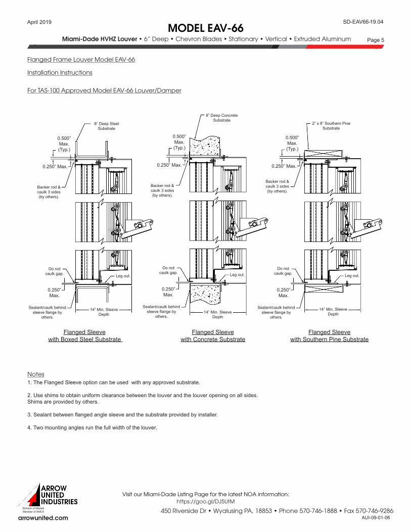
Flanged Frame Louver Model EAV-66
For TAS-100 Approved Model EAV-66 Louver/Damper
Installation Instructions
Notes
14” Min. Sleeve Depth
Backer rod & caulk 3 sides (by others).
Sealant/caulk behind sleeve flange by
others.
Do not caulk gap.
8” Deep Steel Substrate
Leg out.
0.500” Max.(Typ.)
0.250” Max.
0.250” Max.
14” Min. Sleeve Depth
Backer rod & caulk 3 sides (by others).
Sealant/caulk behind sleeve flange by
others.
Do not caulk gap.
8” Deep Concrete Substrate
Leg out.
0.500” Max.(Typ.)
0.250” Max.
0.250” Max.
14” Min. Sleeve Depth
Backer rod & caulk 3 sides (by others).
Sealant/caulk behind sleeve flange by
others.
Do not caulk gap.
2” x 8” Southern Pine Substrate
Leg out.
0.500” Max.(Typ.)
0.250” Max.
0.250” Max.
Flanged Sleevewith Boxed Steel Substrate
Flanged Sleevewith Concrete Substrate
Flanged Sleevewith Southern Pine Substrate
1. The Flanged Sleeve option can be used with any approved substrate.
2. Use shims to obtain uniform clearance between the louver and the louver opening on all sides. Shims are provided by others.
3. Sealant between flanged angle sleeve and the substrate provided by installer.
4. Two mounting angles run the full width of the louver.


![0804 EAV (CFA610)[1]](https://img.pdfslide.net/doc/110x75/577d39a41a28ab3a6b9a3fc6/0804-eav-cfa6101.jpg)