Embed Size (px)
Citation preview

Model EP Series Elevating Prefeeders
ANSI/Metric Installation & Maintenance Manual
Model Number Serial Number/Date
First Edition, Revision 4, All Rights Reserved.Copyright 2015 by Shibuya Hoppmann Corporation.
Duplication of this manual, in whole or in part, requires prior written consent from Shibuya Hoppmann Corporation.
Headquarters Sales Manufacturing7849 Coppermine Dr. 1445 Brookville Way 291 Dillard RoadManassas, VA Suite F Madison Heights, VA20109 Indianapolis, IN 46239 24572540.829.2564 t 317.322.0754 t 434.929.4746 t800.368.3582 t 800.368.3582 t 800.543.0915 t540.829.1726 f 317.322.0794 f 434.929.4959 f
www.ShibuyaHoppmann.com | [email protected]
Refer all servicing to qualified personnel.
This manual is intended for use by qualified mechanics and electricians who install or service the Hoppmann EP Series Elevating Prefeeders.
Record your serial plate information here for future reference Ü
TM

EP Series_3.2015 3 2 EP Series_3.2015
Quick Start
Thank You for Choosing Shibuya Hoppmann Thank you for purchasing a system from Shibuya Hoppmann. Our
prefeeders, feeders, and automated systems possess an industry-wide reputation of excellence for their quiet and rapid handling of parts, ease of use and low maintenance requirements.
About This Manual
Assumptions Shibuya Hoppmann Corporation assumes that all procedures contained in this manual will be performed by a qualified mechanic or electrician who must install or service the EP-Series prefeeders. All procedures in this manual should be performed by qualified personnel or under their direction.
Models Covered This manual covers four (4) styles of prefeeders models: EP-04/06 Elevating Prefeeder, EP-08/15/25 Elevating Prefeeder, EP-10/20/30 Elevating Prefeeder and the EP-35/50 Elevating Prefeeder. If you are unsure of your model, locate the inventory number on the serial plate of your prefeeder.
Before You Start Tools You Will Need The EP Series prefeeders are both "soft ANSI" and metric
construction, meaning that metric threads and hardware are used throughout. The prefeeders require metric tools for repair and/or adjustment.
Equipment Improvements & Shibuya Hoppmann Corporation (SHC) continually improves its products, and reserves Document Revisions Notice the right to change or discontinue specifications and designs shown in this manual
without notice and without incurring obligation. Occasionally older versions of equipment may have different spare parts/replacement parts requirements. Please be sure to contact SHC before ordering specific parts for older style prefeeders. SHC has made every effort to verify the information contained in this manual, but reserves the right to correct any error at the time of the manual’s next revision. 12.2014.

EP Series_3.2015 3 2 EP Series_3.2015
Caution Symbols & Messages
Caution Symbols Caution symbols and messages in this manual call attention to and Messages hazardous voltages, moving parts, and other hazardous
conditions. Please understand what the different warning labels and indicators refer to and how to avoid possible injury and/or damage to personnel and equipment.
The lightning bolt symbol serves as a caution to denote possible personal injury and/or damage to the equipment due to electrical hazards.
The exclamation point symbol serves as a caution to denote possible personal injury and/or damage to the equipment.
Danger - Electrical/Voltage Hazard
The voltages in this system can cause death or serious injury. Service should be performed only by qualified service personnel. Read the safety precautions in Chapter 2 before operating or servicing this system, including any Lockout/Tagout procedures.
Important - Read First

EP Series Prefeeder Installation & Maintenance Manual
EP Series_3.2015 5 4 EP Series_3.2015
Danger - Mechanical Hazard
To reduce the risk of injury from moving parts, keep all safety covers in place, secure loose clothing, and wear safety glasses or other protective eye wear when operating machine.
To reduce the risk of injury from moving parts, padlock and tag the main electrical and pneumatic disconnects before adjusting or replacing change parts or performing mechanical maintenance. Ensure that power is off and cannot be reactivated accidentally.
EP Series_3.2015 5 4 EP Series_3.2015
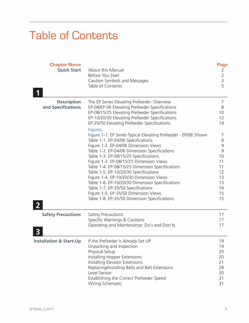
Quick Start About this Manual 2 Before You Start 2 Caution Symbols and Messages 3 Table of Contents 5
Description The EP Series Elevating Prefeeder: Overview 7 and Specifications EP-04/EP-06 Elevating Prefeeder Specifications 8 EP-08/15/25 Elevating Prefeeder Specifications 10 EP-10/20/30 Elevating Prefeeder Specifications 12 EP-35/50 Elevating Prefeeder Specifications 14
Figures: Figure 1-1. EP Series Typical Elevating Prefeeder - EP/08 Shown 7 Table 1-1. EP-04/06 Specifications 8 Figure 1-2. EP-04/06 Dimension Views 9 Table 1-2. EP-04/06 Dimension Specifications 9 Table 1-3. EP-08/15/25 Specifications 10 Figure 1-3. EP-08/15/25 Dimension Views 11 Table 1-4. EP-08/15/25 Dimension Specifications 11 Table 1-5. EP-10/20/30 Specifications 12 Figure 1-4. EP-10/20/30 Dimension Views 13 Table 1-6. EP-10/20/30 Dimension Specifications 13 Table 1-7. EP-35/50 Specifications 14 Figure 1-5. EP-35/50 Dimension Views 15 Table 1-8. EP-35/50 Dimension Specifications 15
Safety Precautions Safety Precautions 17 Specific Warnings & Cautions 17 Operating and Maintenance: Do's and Don'ts 17
Installation & Start-Up If the Prefeeder is Already Set UP 19 Unpacking and Inspection 19 Physical Setup 20 Installing Hopper Extensions 20 Installing Elevator Extensions 21 Replacing/Installing Belts and Belt Extensions 28 Level Sensor 30 Establishing the Correct Prefeeder Speed 31 Wiring Schematic 31
Table of Contents
Chapter Name Page
1
2
3

EP Series_3.2015 7 6 EP Series_3.2015
Installation & Start-Up Figures: (Continued) Figure 3-1. Sample Serial Plate 19 Figure 3-2. Take-Up Pulley 21 Figure 3-3. Remove Lacing Pin to Remove Belt 21 Figure 3-4. Disconnect Power 22 Figure 3-5. Remove Elevator Cover 22 Figure 3-6. Pull Belt out to Remove Head 22 Figure 3-7. Left Hand and Right Hand Exit Guides 23 Figure 3-8. Side Guides - Remove Hardware 23 Figure 3-9. Extension Kit for Prefeeder Extension 24 Figure 3-10. Attach New Belt Extension to Existing Belt 25 Figure 3-11. Tracking Adjustment of Belt Made to Belt Tensioner 26 Figure 3-12. Adjusting the Dump Height Suspension Points 26 Table 3-1. Dump Height Reference Chart 27 Figure 3-13. Re-Installing Lacing Pin 28 Table 3-2. One Piece Extensions - Belt Replacement 29 Table 3-3. Extension Only - Belt Replacement 30 Figure 3-14. Wiring Diagram - AC Prefeeders 31
Preventive Upper Drive Pulley 33 Maintenance Lower Take-Up Pulley 35 Reducers 36 Routine Cleaning 36
Figures: Figure 4-1. Drive Pulley (Head) with DC Motor/Reducer 33 Figure 4-2. Drive Pulley (Head) with AC Gear Motor 34 Figure 4-2. Lower Take-Up Pulley Sub-Assembly 35
Replacement Parts Replacement Parts 37 EP-04/06 Elevating Prefeeders 38 EP-08/15/25 Elevating Prefeeders 40 EP-10/20/30 Elevating Prefeeders 42 EP-35/50 Elevating Prefeeder 44
Figures: Figure 5-1. Sample Serial Plate 37 Warranty Warranty 47
6
Table of Contents
Chapter Name Page
3
4
5
6
EP Series_3.2015 7 6 EP Series_3.2015
Description & Specifications
1The EP Series Elevating Prefeeder: Overview
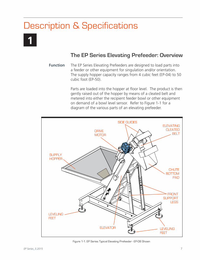
Function The EP Series Elevating Prefeeders are designed to load parts into a feeder or other equipment for singulation and/or orientation. The supply hopper capacity ranges from 4 cubic feet (EP-04) to 50 cubic foot (EP-50).
Parts are loaded into the hopper at floor level. The product is then gently raised out of the hopper by means of a cleated belt and metered into either the recipient feeder bowl or other equipment on demand of a bowl level sensor. Refer to Figure 1-1 for a diagram of the various parts of an elevating prefeeder.
DRIVE MOTOR
CHUTE BOTTOM
PAD
LEVELINGFEET
FRONT SUPPORT
LEGS
SIDE GUIDES
Figure 1-1. EP Series Typical Elevating Prefeeder - EP-08 Shown
ELEVATING CLEATED
BELT
SUPPLYHOPPER
ELEVATOR LEVELINGFEET

EP Series Prefeeder Installation & Maintenance Manual
EP Series_3.2015 9 8 EP Series_3.2015
EP-04/EP-06 Elevating Prefeeder Specifications
Standard Features The stainless steel constructed EP-04 and EP-06 elevating prefeeders come standard with an FDA/USDA approved white 1-ply solid woven polyester fabric belt, with .156" thick white PVC coating and standard 1.50" tall cleats.
Optional Features Elevator extension, hopper extensions, continuous welded hoppers, integrated safety covers, washdown motors, NEMA 1 encased controller, pneumatic hopper agitators and casters are optional equipment for the EP-04.
Specifications Please refer to the tables below for EP-04/06 specifications:
Table 1-1. EP-04/06 Specifications
Specifications DC AC
Motor Size 1/5hp 1/4hp
Motor Frame Size 56C 56C
Supply Voltage 90VDC 230/460 VAC
Average Belt Speed 35'/min. 10.67 meters/min.
Cleat Height (Nominal) 1.50" 38.10mm
Cleat Pitch 6.00" 152.40mm
EP-04 Hopper Capacity 4 ft3
113 liters
EP-06 Hopper Capacity 6 ft3
170 liters

EP Series_3.2015 9 8 EP Series_3.2015
Chapter 1 Feeder Description and Specifications
Dimension Specifications ANSI Metric
A Overall Width 34" 865mm
B Overall Length 62" 1575mm
C Lower Chassis Footprint 46" 1168mm
D Dump Height (Adjustable) 42" 1067mm
E Hopper Load Height (EP-04) 31" 787mm
E Hopper Load Height (EP-06) 35" 889mm
F Belt Width 6" 152mm
G Discharge Chute Height 23.5" 597mm
H Level Foot Adjustment 2" 51mm
Overall Weight 250 lbs. 113.4 kgTable 1-2. EP-04/06 Dimension Specifications
Figure 1-2. EP-04/06 Dimension Views
F
A CB
E
D
G

EP Series Prefeeder Installation & Maintenance Manual
EP Series_3.2015 11 10 EP Series_3.2015
EP-08/EP-15/EP-25 Elevating Prefeeder Specifications
Standard Features The stainless steel constructed EP-08/15/25 elevating prefeeders come standard with an FDA/USDA approved white 1-ply solid woven polyester fabric belt, with .156" thick white PVC coating and standard 2.00" tall cleats, hopper cleanout door and one piece formed hopper (8 cubic foot standard).
Optional Features Elevator extensions, hopper extensions, continuous welded hoppers (for EP-15 and EP-25), integrated safety covers, washdown motors, NEMA 1 encased controller, pneumatic hopper agitators and casters are optional equipment.
Specifications Please refer to the tables below for EP-08/15/25 specifications:
Table 1-3. EP-08/15/25 Specifications
Specifications DC AC
Motor Size 1/4hp 186w
Motor Frame Size 56C 56C
Supply Voltage 90VDC 230/460VAC
Average Belt Speed 32'/min. 9.75 meters/min.
Cleat Height (Nominal) 2.00" 50.80mm
Cleat Pitch 6.00" 152.40mm
EP-08 Hopper Capacity 8 ft3
227 liters
EP-15 Hopper Capacity 15 ft3
425 liters
EP-25 Hopper Capacity 25 ft3
708 liters

EP Series_3.2015 11 10 EP Series_3.2015
Chapter 1 Feeder Description and Specifications
Dimension Specifications ANSI Metric
A Overall Width 42" 1067mm
B Overall Length 73" 1854mm
C Lower Chassis Footprint 63.10" 1603mm
D Dump Height (Adjustable) 42" - 53" 1067-1346mm
E Hopper Load Height (EP-08) 34" 864mm
E Hopper Load Height (EP-15) 42" 1067mm
E Hopper Load Height (EP-25) 50" 1270mm
F Belt Width 8" 203mm
G Discharge Chute Height 25.5" 648mm
Overall Weight 720 lbs. 327kg
Table 1-4. EP-08/15/25 Dimension Specifications
Figure 1-3. EP-08/15/25 Dimension Views
��
�
�
�
�
�

EP Series Prefeeder Installation & Maintenance Manual
EP Series_3.2015 13 12 EP Series_3.2015
EP-10/20/30 Elevating Prefeeder Specifications
Standard Features The EP-10/20/30 elevating prefeeder is designed to handle a variety of medium-sized, mid-weight parts. Its 10 ft
3 capacity
hopper delivers product at an average belt speed of 32’/minute. The 12” wide cleated elevator belt has a nominal cleat height of 2.00” and a cleat pitch of 9.00” allowing for maximum product loading. A heavy duty variable speed motor helps to ensure proper product metering.
Optional Features Elevator extensions, hopper extensions, integrated safety covers, washdown motors, NEMA 1 encased controller, pneumatic hopper agitators and casters are optional equipment.
Specifications Please refer to the tables below for EP-10/20/30 specifications:
Table 1-5. EP-10/20/30 Specifications
Specifications DC AC
Motor Size 1/4hp 186w
Motor Frame Size 56C 56C
Supply Voltage 90VDC 230/460VAC
Average Belt Speed 32'/min. 9.75 meters/min.
Cleat Height (Nominal) 2.00" 50.80mm
Cleat Pitch 9.00" 228.6mm
EP-10 Hopper Capacity 10 ft3
283 liters
EP-20 Hopper Capacity 20 ft3
566 liters
EP-30 Hopper Capacity 30 ft3
850 liters

EP Series_3.2015 13 12 EP Series_3.2015
Chapter 1 Feeder Description and Specifications
Dimension Specifications ANSI Metric
A Overall Width 46.10" 1171mm
B Overall Length 72.69" 1846mm
C Lower Chassis Footprint 62.98" 1600mm
D Dump Height (Adjustable) 48.90" 1242mm
E Hopper Load Height (EP-10) 37.24" 946mm
E Hopper Load Height (EP-20) 46.24" 1174mm
E Hopper Load Height (EP-30) 55.24" 1403mm
F Belt Width 12" 305mm
G Discharge Chute Height 25.5" 648mm
Overall Weight 740 lbs. 336kg
Table 1-6. EP-10/20/30 Dimension Specifications
Figure 1-4. EP-10/20/30 Dimension Views
B
A F
E
C
D
G

EP Series Prefeeder Installation & Maintenance Manual
EP Series_3.2015 15 14 EP Series_3.2015
EP-35/EP-50 Elevating Prefeeder Specifications
Standard Features The stainless steel constructed EP-35/50 elevating prefeeders come standard with an FDA/USDA approved white 1-ply solid woven polyester fabric belt, with .156" thick white PVC coating and standard 3.00" tall cleats, and hopper cleanout door.
Optional Features Elevator extensions, hopper extensions, continuous welded hoppers, integrated safety covers, washdown motors, NEMA 1 encased controller, and casters are optional equipment.
Specifications Please refer to the tables below for EP-35/50 specifications:
Table 1-7. EP-35/50 Specifications
Specifications DC AC
Motor Size 1/2hp 373w
Motor Frame Size 56C 56C
Supply Voltage 90VDC 230/460VAC
Average Belt Speed 23'/min. 7.01 meters/min.
Cleat Height (Nominal) 3.00" 76.2mm
Cleat Pitch 12.00" 304.80mm
EP-35 Hopper Capacity 35 ft3
991 liters
EP-50 Hopper Capacity 50 ft3
1416 liters

EP Series_3.2015 15 14 EP Series_3.2015
Chapter 1 Feeder Description and Specifications
Dimension Specifications ANSI Metric
A Overall Width 72" 1829mm
B Overall Length 95" 2413mm
C Lower Chassis Footprint 76.62" 1947mm
D Dump Height (Adjustable) 45" - 58" 1143-1473mm
E Hopper Load Height (EP-35) 45" 1143mm
E Hopper Load Height (EP-50) 51" 1295mm
F Belt Width 18" 457mm
G Discharge Chute Height 25.5" 648mm
Overall Weight 1200 lbs. 544 kgTable 1-8. EP-35/50 Dimension Specifications
Figure 1-5. EP-35/50 Dimension Views Views
��
�
F
�
�
�
�

EP Series Prefeeder Installation & Maintenance Manual
EP Series_3.2015 17 16 EP Series_3.2015
Notes

EP Series_3.2015 17 16 EP Series_3.2015
Safety Precautions
2Safety Precautions
This prefeeder has been designed to be as safe as possible for operators. However, even well-built machines can be installed or operated in a hazardous manner. Safety precautions must be observed by users.
Specific Warnings & Cautions
Turn Power Off! Before servicing the prefeeder, make sure you have turned off compressed air and electrical power in a way that prevents accidental reactivation. Padlock, and clearly tag, the appropriate electrical and pneumatic disconnects. Lockout/Tagout procedures are covered in the United States Code of Federal Regulation (CFR), Title 29, Part 1910.147, “The Control of Hazardous Energy.”
Dress Properly. To reduce the risk of injury from moving parts, secure loose clothing. Do not wear jewelry or neckties near the prefeeder. Wear safety glasses or other protective eye wear when operating or performing maintenance on the prefeeder. Never place hands or tools in the prefeeder while it is operating.
Install Safety Covers. Make sure the prefeeder remains safe to operate. Be sure all safety covers have been installed before returning the prefeeder to normal operations. Safety covers on the prefeeder include any covers installed by your direct supplier, as well as standard, permanent guarding.
Operating & Maintenance: Do's & Don'ts
Don't Install the Prefeeder Near Flammable Gas, Vapor or Dust. You must install additional approved explosion-proof or dust-ignition-proof enclosures if installation occurs under these conditions. Without such additional enclosures, normal sparking of the brushes inside the (DC) motor could ignite flammable gas, vapor, or dust.

EP Series_3.2015 19 18 EP Series_3.2015
Operations Manual
Do Not Overfill The Hopper. Overfilling the hopper can cause parts to jam inside the hopper, and may damage the prefeeder belt and associated guides.
Do Use the Same or Identical Mounting Screws if Replacing the Motor. If longer mounting screws are used, they may come into contact with parts of the motor that conduct electricity.
Ensure Air is On. Before turning on the system, be sure air is on, or parts may jam. This only applies to systems operating with air.
Do Not Speed Up Prefeeder. Never raise the prefeeder speed to increase the delivery rate. Too many parts in the feeder may prevent it from operating properly.
Avoid Solvents. Do not use solvents for cleaning unless specified, as they may damage surfaces, causing jams or lowered output rates.
Avoid Routine Use of EMERGENCY STOP or E-STOP. Use of EMERGENCY STOP (E-STOP) to shut down the system may cause jams or misoriented parts.

EP Series_3.2015 19 18 EP Series_3.2015
TM
SERIAL # DATEMODEL #INVENTORY #PROJECT NUMBER
www.shibuyahoppmann.com • (800) 368-3582
Installation & Start-Up
3If the Prefeeder is Already Set Up
If you’ve bought a prefeeder as part of a Shibuya Hoppmann feeder system, then your direct supplier will have performed all the procedures in this chapter. However, you will still need to:
p Position Your Prefeeder. Follow the equipment layout drawing provided by your direct supplier.
p Connect Electrical Wiring. Follow as-built electrical diagrams provided by your direct supplier.
p Make Pneumatic Connections. If your prefeeder has a hopper agitator, your direct supplier will give you setup specifications.
p Install and Test the Rest of the System. Installation is complete.
Note: If the prefeeder is drop-shipped to your location, follow the procedures in this chapter to finish setting up the prefeeder.
Unpacking and Inspection
Step 1– Inspect and Unpack the Crate. Remove packing materials from sensors, covers, and moving parts. Make a visual check to be sure parts have not come loose during shipping. If you find any concealed damage, call the shipping carrier and your direct supplier immediately. Do not attempt to fix the problem yourself unless told to do so by your direct supplier.
Step 2– Record Serial Number of Prefeeder. If you have not already done so, record the prefeeder’s model and serial number on the front of this manual. This information is helpful when ordering replacement parts or service. Figure 3-1. Sample Serial Plate
000XXX MM/DDEP 08 with 18" EXTENSION EP0808XDSA SAMPLE
EP Series Prefeeder Installation & Maintenance Manual
EP Series_3.2015 21 20 EP Series_3.2015
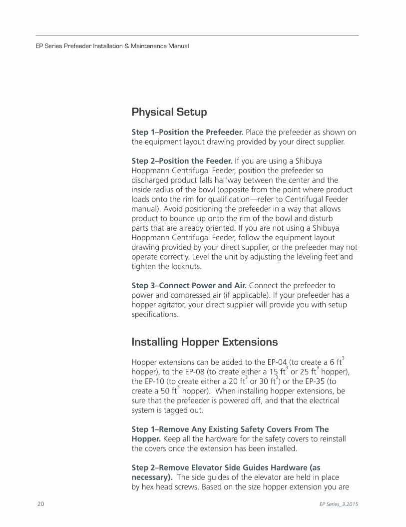
Physical Setup
Step 1–Position the Prefeeder. Place the prefeeder as shown on the equipment layout drawing provided by your direct supplier.
Step 2–Position the Feeder. If you are using a Shibuya
Hoppmann Centrifugal Feeder, position the prefeeder so discharged product falls halfway between the center and the inside radius of the bowl (opposite from the point where product loads onto the rim for qualification—refer to Centrifugal Feeder manual). Avoid positioning the prefeeder in a way that allows product to bounce up onto the rim of the bowl and disturb parts that are already oriented. If you are not using a Shibuya Hoppmann Centrifugal Feeder, follow the equipment layout drawing provided by your direct supplier, or the prefeeder may not operate correctly. Level the unit by adjusting the leveling feet and tighten the locknuts.
Step 3–Connect Power and Air. Connect the prefeeder to power and compressed air (if applicable). If your prefeeder has a hopper agitator, your direct supplier will provide you with setup specifications.
Installing Hopper Extensions
Hopper extensions can be added to the EP-04 (to create a 6 ft3
hopper), to the EP-08 (to create either a 15 ft3
or 25 ft3 hopper),
the EP-10 (to create either a 20 ft3 or 30 ft
3) or the EP-35 (to
create a 50 ft3
hopper). When installing hopper extensions, be sure that the prefeeder is powered off, and that the electrical system is tagged out.
Step 1–Remove Any Existing Safety Covers From The Hopper. Keep all the hardware for the safety covers to reinstall the covers once the extension has been installed.
Step 2–Remove Elevator Side Guides Hardware (as necessary). The side guides of the elevator are held in place by hex head screws. Based on the size hopper extension you are

EP Series_3.2015 21 20 EP Series_3.2015
installing, remove the corresponding hardware on the side guides. When you install the extension, you will reuse the same hardware to attach the extension to the side guides.
Step 3–Align New Hopper Extension. The hopper extension is a welded, one-piece unit that fits atop the existing hopper. Align the extension, using the pre drilled holes in the extension and the existing hopper as guides. Once aligned, use the hardware provided with the extension to secure it into place atop the base hopper.
Step 4–Reinstall Side Guide Hardware & Safety Covers. Reinstall all side guide screws (through new hopper extension holes and side guide holes). Reinstall all safety covers (if necessary).
Installing Elevator Extensions
When adding elevator extensions, the prefeeder’s higher center of gravity may cause it to tip. Before installation, take necessary steps to stabilize the prefeeder. To avoid possible injury, have someone assist you by supporting the head section during removal and installation.
Step 1–Loosen Take-Up Pulleys and Remove Belt Lacing
Pin. To install an elevator extension to an EP series prefeeder, first
Chapter 3 Installation & Start-Up
Figure 3-3. Remove Lacing Pin to Remove Belt
HOPPER INTERIOR
REMOVELACING PIN
Figure 3-2. Take-Up Pulley
LOOSEN NUTSTO ADJUST TENSIONON TAkE-UP PULLEY

EP Series Prefeeder Installation & Maintenance Manual
EP Series_3.2015 23 22 EP Series_3.2015
rotate the belt so that splice area (location of the lace and pin, see Figure 3-3) are located in the interior of the hopper, just below the side guides. This position will allow easy access to the belt pin for removal. Loosen both sides of the lower pulley take-up brackets (see Figure 3-2). With the belt now loose, remove the belt lace pin.
Once the pin has been removed, slide the upper portion of the belt up the elevator channel and out the dump chute of the prefeeder's head. You do not need to remove the belt completely, as it is easier to re-fix the belt once the extension has been added.
Step 2–Disconnect Power and Lockout/Tag Out the Prefeeder. If power has already been supplied to the prefeeder, first lock out and tag out the power supply, then disconnect the wiring to the drive motor (undo the nut at the base of the motor connection box and disconnect wiring - see Figure 3-4). Figure 3-4. Disconnect Power
DISCONNECTMOTOR
Figure 3-5. Remove Elevator Cover
ELEVATOR(CHANNEL)
COVER
Figure 3-6. Pull Belt Out to Remove Head
PULL BELT OUT
TO HANG
EASILY REMOVEPREFEEDER HEAD

EP Series_3.2015 23 22 EP Series_3.2015
Chapter 3 Installation & Start-Up
Step 3–Remove Channel Cover. Located on the underside of the prefeeder's elevator is a cover over the belt return (Figure 3-5). Undo the four hex bolts that hold the upper cover plate in place, and set the plate aside. Pull the belt down from the prefeeder's head, and let the belt hang (see Figure 3-6).
Step 4–Remove Prefeeder Head. Remove the side guide bolts
on the prefeeder head. This frees the two exit guides (left hand and right hand) which help guide the belt. Set these exit guides (see Figure 3-7) to the side. Remove any hardware on the side guides from the head portion of the prefeeder, and set aside. You will not be removing the side guides on the channel, just disconnecting them. Then remove the two bolts on both sides of the prefeeder channel or neck (see Figure 3-8) and set aside.
The head of the prefeeder (with the drive motor assembly) should be supported during this removal process. Guide the head up and off the neck of the prefeeder, allowing the belt to slide through the chute area, remaining "attached" to the prefeeder. Set the head to the side.
Figure 3-7. Left Hand and RightHand Exit Guides
EXIT GUIDESREMOVE FROM
PREFEEDER HEAD
Figure 3-8. Side Guides - Remove Hardware
LH AND RHSIDE GUIDESREMAINATTACHED
LOOSEN AND REMOVEUPPERMOST
TWO (2) HEX HEADBOLTS FROM EACH
SIDE OF THE GUIDES
REMOVE NECkBOLTS TO
REMOVE HEAD

EP Series Prefeeder Installation & Maintenance Manual
EP Series_3.2015 25 24 EP Series_3.2015
Step 5–Inventory the Elevator Extension Kit. The extension kit will include the following: Channel Extension (1), Side Guide Extension (2), Splice Plates (2), Channel Cover (1), associated hardware, and Belt Extension (see Figure 3-9 above).
Step 6–Install Extension. Attach the splice plates to the extension channel (inside), hand-tightening the bolts prior to installing the extension on the prefeeder. Then lift the extension up slide it onto the prefeeder neck, securing it with hand-tightened hex head bolts (2). Before tightening the bolts, align the seams of the existing channel and the new extension as closely as possible. Tighten the extension channel bolts and splice plate bolts at this time.
Step 7–Re-Install the Prefeeder Head. Reinstall the head of the prefeeder over the new extension, aligning the head's splice plates with the holes on the extended neck. Hand tighten the bolts, then tighten them once the pieces are aligned.
Figure 3-9. Extension kit for Prefeeder Extension
SIDEGUIDES(2)
CHANNELCOVER
EXTENSIONCHANNEL
SPLICE PLATES(2)
HEX HEAD NUTS & BOLTS w/ LOCkING WASHERS AND
FLAT WASHERSBELT EXTENSION PIECE (WITHLACING ON BOTH ENDS AND PIN)

EP Series_3.2015 25 24 EP Series_3.2015
Chapter 3 Installation & Start-Up
Step 8–Re-Install LH/RH Exit Guides and New Side Guides. Replace the left hand and right hand exit guides (removed in Step 4) and align the new side guide extensions along the channel, using the holes provided in the channel. Once aligned, attach with the new hardware (Figure 3-9).
Figure 3-10. Attach New Belt Extension to Existing Belt
EXISTINGBELT
NEWEXTENSION
BELT
LACING PIN
BELT LACING
Step 9–Attach New Belt Extension. Both ends of the new extension belt are laced. Attach one end of the belt extension to the part of the belt hanging out of the prefeeder's channel (Figure 3-6), using the lacing pin to lock both ends together (Figure 3-10). Feed the belt back through the neck of the prefeeder and through the head, letting it flow down the elevator of the prefeeder towards the hopper. Attach the other end of the belt extension to the end of the belt rising up from the base of the hopper. Retighten the take-up pulley to apply some tension to the belt (refer to Step 12 for more information on tracking/adjusting your belt).
Step 10–Install the Elevator Covers. Reinstall the elevator cover and the new elevator cover extension on the underside of the prefeeder.
Step 11–Reconnect Power. Restore power to the motor.

EP Series Prefeeder Installation & Maintenance Manual
EP Series_3.2015 27 26 EP Series_3.2015
Step 12–Adjust Tracking. Turn the prefeeder on and set to a slow speed to observe tracking of the belt. Run a new belt at least several complete revolutions before adjusting the tracking. If the belt pulls to one side or if the belt moves from side to side, adjust the tensioner bracket on the side to which the belt is pulling (see Figure 3-11).
Do not overtighten the belt. The elevator extensions added call for greater slack in the belt. This is normal, and should not be adjusted by overcompensating for the slack. You may apply too much tension and destroy the belt lacing. For more information on belt tracking, refer to "Installing Belts and Belt Extensions" further in this chapter.
Figure 3-11. Tracking Adjustment of Belt Made to Belt Tensioner
BELT TAkE-UP ADJUSTMENT
BRACkETBELTTENSIONERBRACkET
Figure 3-12. Adjusting the DumpHeight Suspension Points
SUSPENSIONPOINTS
SUSPENSIONPOINTS
Step 13–Adjust Dump Heights. Once the extension is installed, you may need to adjust the dump height by more than the leveling feet will allow. To adjust the dump height of the prefeeder, loosen the six suspension points which connect the elevator and front legs to the frame of the prefeeder on both sides (see Figure 3-12). This allows the unit to pivot when adjusting the dump height once the two bolts in the telescoping portion
EP Series_3.2015 27 26 EP Series_3.2015
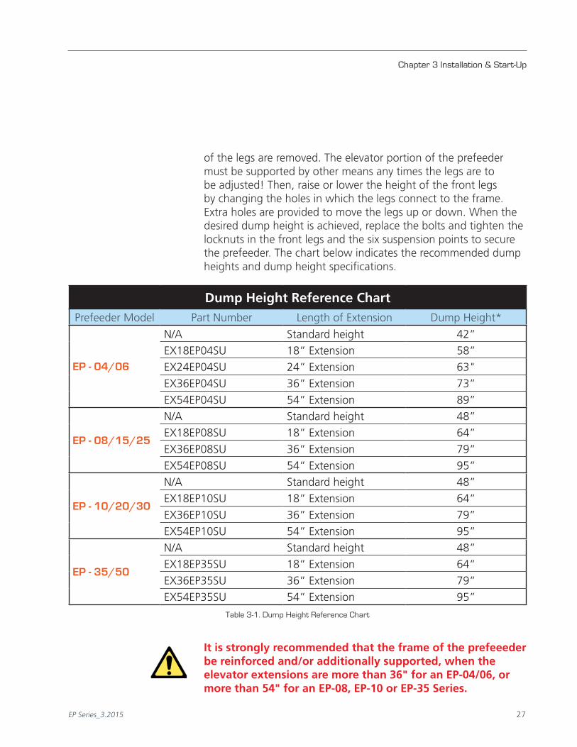
Dump Height Reference ChartPrefeeder Model Part Number Length of Extension Dump Height*
EP - 04/06
N/A Standard height 42”
EX18EP04SU 18” Extension 58”
EX24EP04SU 24” Extension 63"
EX36EP04SU 36” Extension 73”
EX54EP04SU 54” Extension 89”
EP - 08/15/25
N/A Standard height 48”
EX18EP08SU 18” Extension 64”
EX36EP08SU 36” Extension 79”
EX54EP08SU 54” Extension 95”
EP - 10/20/30
N/A Standard height 48”
EX18EP10SU 18” Extension 64”
EX36EP10SU 36” Extension 79”
EX54EP10SU 54” Extension 95”
EP - 35/50
N/A Standard height 48”
EX18EP35SU 18” Extension 64”
EX36EP35SU 36” Extension 79”
EX54EP35SU 54” Extension 95”
Chapter 3 Installation & Start-Up
of the legs are removed. The elevator portion of the prefeeder must be supported by other means any times the legs are to be adjusted! Then, raise or lower the height of the front legs by changing the holes in which the legs connect to the frame. Extra holes are provided to move the legs up or down. When the desired dump height is achieved, replace the bolts and tighten the locknuts in the front legs and the six suspension points to secure the prefeeder. The chart below indicates the recommended dump heights and dump height specifications.
It is strongly recommended that the frame of the prefeeeder be reinforced and/or additionally supported, when the elevator extensions are more than 36" for an EP-04/06, or more than 54" for an EP-08, EP-10 or EP-35 Series.
Table 3-1. Dump Height Reference Chart

EP Series Prefeeder Installation & Maintenance Manual
EP Series_3.2015 29 28 EP Series_3.2015
A base extension support kit may be purchased from Shibuya Hoppmann Corporation, however, they may need to be customized for your prefeeder. Please contact Shibuya Hoppmann Corporation for additional information on this frame base kit.
Replacing/Installing Belts and Extensions
Step 1–Disconnect Power and Lockout/Tag Out the Prefeeder. Lockout and tag out any power supply to the prefeeder.
Step 2–Install Belt. Install the belt by feeding it through the prefeeder's hopper (downward), up the underside of the elevator channel, through the head, and back down the elevator channel into the hopper, cleats facing up. The belt lacings on both ends of the belt, should meet in the hopper area of the prefeeder (see Figure 3-13). You may need to remove the elevator covers (underside of the prefeeder channel) to feed the belt. Once the belt is completely fed into the prefeeder, and the lacing pin installed, replace the elevator covers.
Step 3–Tension Belt. Use the tensioner brackets on the base of the prefeeder (see Figure 3-11) to remove excessive slack in the belt before beginning tracking.
Do not overtighten the belt. When tightening the take-up pulley, apply minimum tension necessary to take up slack and properly track the belt. If you apply too much tension, you can easily destroy the belt lacing or decrease the life of the pulley bearings.
Step 4–Turn on Power and Adjust Tracking. Restore power to the prefeeder and turn it on, setting it to a slow speed to observe tracking of the belt. Run a new belt at least several complete revolutions before adjusting the tracking. If the belt pulls to one side or if the belt moves from side to side, adjust the tensioner bracket on the side to which the belt is pulling (see Figure 3-11.)
Figure 3-13. Re-Installing Lacing Pin
HOPPER INTERIOR
RE-INSTALLINGLACING PIN

EP Series_3.2015 29 28 EP Series_3.2015
Step 5–Adjust Tracking Again. Run the prefeeder for at least
five (5) minutes. Continue to adjust tracking until the prefeeder runs consistently without tracking problems.
Step 6–Adjust Tensioning. A properly tensioned belt will not slip with a hopper full of product. To avoid injury, turn off the prefeeder before checking tension. Tighten or loosen the tension equally to ensure proper tension. Tighten the locknuts of the tension rod.
Do not set tools where they can fall into the hopper or any moving parts.
Replacement Belts Extension - One Piece Belts - Reference ChartPrefeeder Model Part Number Length of Extension Extension Belt Length
EP - 04/06
BELTEP4126 Standard 126”
BELTEP4162 18” Extension 162"
BELTEP4174 24” Extension 174"
BELTEP4198 36” Extension 198"
BELTEP4234 54” Extension 234"
EP - 08/15/25
BELTEP8144 Standard 144"
BELTEP8180 18” Extension 180"
BELTEP8216 36” Extension 216"
BELTEP8252 54” Extension 252"
EP - 10/20/30
BELTEP10144 Standard 144"
BELTEP10180 18” Extension 180"
BELTEP10216 36” Extension 216"
BELTEP10252 54” Extension 252"
EP - 35/50
BELTEP35168 Standard 168"
BELTEP35204 18” Extension 204"
BELTEP35240 36” Extension 240"
BELTEP35276 54” Extension 276"Table 3-2. One Piece Extension - Belt Replacement
Chapter 3 Installation & Start-Up

EP Series Prefeeder Installation & Maintenance Manual
EP Series_3.2015 31 30 EP Series_3.2015
Replacement Belts - Extension Belt Only - Reference ChartPrefeeder Model Description Part Number Extension Belt Length
EP - 04/06
18" Extension BELTEP4036 36"
24" Extension BELTEP4048 48"
36" Extension BELTEP4072 72"
54" Extension BELTEP4108 108"
EP - 08/15/2518" Extension BELTEP8036 36"
36" Extension BELTEP8072 72"
54" Extension BELTEP8108 108"
EP - 10/20/3018" Extension BELTEP10036 36"
36" Extension BELTEP10072 72"
54" Extension BELTEP10108 108"
EP - 35/5018" Extension BELTEP35036 36"
36" Extension BELTEP35072 72"
54" Extension BELTEP35108 108"
Table 3-3. Extension Only - Belt Replacement
Do not overtighten the belt. The elevator extensions added call for greater slack in the belt. This is normal, and should not be adjusted by overcompensating for the slack. You may apply too much tension and destroy the belt lacing.
Level Sensor
The most common method of controlling the prefeeder is with a level sensing device. This device monitors the down stream equipment and tells the prefeeder when to supply product by activating the motor on the prefeeder for a duration of time. The sensor keeps the level of product, from the prefeeder to the equipment, relatively constant by controlling the amount of product metered into the receiving equipment. For further information contact Shibuya Hoppmann Corporation, or your direct supplier.

EP Series_3.2015 31 30 EP Series_3.2015
Establishing the Correct Prefeeder Speed
The speed of the prefeeder should be set so that the minimum amount of product is in the feeder (or other equipment), and the required rate is still obtained. You may have to adjust the settings, and count product to find the optimum speed.
Wiring Schematics
The wiring schematic for prefeeders with AC drives is show in Figure 3-14. The following page shows the motors and reducers for the EP Series elevating prefeeders.
Chapter 3 Installation & Start-Up
Figure 3-14. Wiring Diagram - AC Prefeeders
FRAME LOW VOLTAGE HIGH VOLTAGE
T6
T1
T4
T2
T5
T3
L1 L2 L3
T1 T2 T3
L1 L2 L3
T6 T4 T5SINGLESPEED

EP Series Prefeeder Installation & Maintenance Manual
EP Series_3.2015 33 32 EP Series_3.2015
Notes

EP Series_3.2015 33 32 EP Series_3.2015
Preventive Maintenance
4Upper Drive Pulley
There are two different designs for the Upper Drive Pulley of the EP Series prefeeders. Please determine if your prefeeder is designed with a motor/reducer drive combination, or with the Brother gear motor drive, and refer to the correct section in this chapter for maintenance/repair.
Motor/Reducer Style The main components of the upper drive pulley assembly are a drive motor and gear reducer, a drive coupling and a pair of flanged bearings. Each bearing assembly consists of a bearing insert (bearing plus a clamp collar) and a pair of bearing flanges. Refer to Figure 4-1 for part description. The bearing inserts are lubrication free. If a bearing requires replacement, the bearing flanges can be reused if they appear unworn and undamaged.
Figure 4-1. Drive Pulley (Head) with DC Motor/Reducer Sub-Assembly
2
3
4
LEFT CHUTE SIDE
MOTORBRACkET AND COVERS MOTOR
REDUCERCOUPLING SPIDER
COUPLING HALF
COUPLING HALF
3
1
4
2
RIGHT CHUTE SIDE
PULLEY
DRIVESHAFT
1
1
BEARING INSERT, 25mm(BRNGINSM01) AND
STAINLESS STEEL FLANGES
EP Series Prefeeder Installation & Maintenance Manual
EP Series_3.2015 35 34 EP Series_3.2015
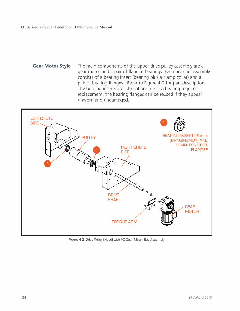
Gear Motor Style The main components of the upper drive pulley assembly are a gear motor and a pair of flanged bearings. Each bearing assembly consists of a bearing insert (bearing plus a clamp collar) and a pair of bearing flanges. Refer to Figure 4-2 for part description. The bearing inserts are lubrication free. If a bearing requires replacement, the bearing flanges can be reused if they appear unworn and undamaged.
Figure 4-2. Drive Pulley (Head) with AC Gear Motor Sub-Assembly
LEFT CHUTE SIDE
TORQUE ARM
GEAR MOTOR
1
RIGHT CHUTE SIDE
PULLEY
DRIVESHAFT
1
1
BEARING INSERT, 25mm(BRNGINSM01) AND
STAINLESS STEEL FLANGES

EP Series_3.2015 35 34 EP Series_3.2015
Chapter 4 Preventive Maintenance
Lower Take-Up Pulley
The main components of the lower take-up pulley assembly consist of two belt tensioner brackets, a take-up shaft, two bearing assemblies and a drive pulley (see Figure 4-2). Like the drive pulley bearings, each bearing assembly consists of a bearing insert (bearing plus a clamp collar) and a pair of bearing flanges. The bearing inserts are lubrication free. If a bearing requires replacement, the bearing flanges can be reused if they appear unworn and undamaged.
BELT TENSIONER
BRACkET
CONVEYORCHANNEL
PULLEY
BELTADJUSTMENTBRACkET
TAkE-UPSHAFT
BELT TENSIONER BRACkET
Figure 4-2. Lower Take-Up Pulley Sub-Assembly
BEARING INSERT, 25mm(BRNGINSM01) ANDSTAINLESS STEEL FLANGES
1
1
1

EP Series Prefeeder Installation & Maintenance Manual
EP Series_3.2015 37 36 EP Series_3.2015
Reducers
The reducers are lubricated for life and maintenance free.
Routine Cleaning
When necessary, clean the belt surface with a cloth dampened with water, or you can use a mild household cleaner. Wipe off damp surfaces with a dry, clean cloth.
The entire prefeeder can be wiped down with a clean cloth, and stainless steel cleaner may be used if needed. Do not use any type of abrasive cleanser on the equipment.

EP Series_3.2015 37 36 EP Series_3.2015
Replacement Parts
5Replacement Parts
Replacement parts lists for the Hoppmann prefeeders are listed on the following pages. When ordering replacement parts, please reference the model name and number of your feeder located on the serial plate (see Figure 5-1). This helps in making sure you receive the correct replacement parts.
If you received a customized Shibuya Hoppmann system, please refer to your system's Operation Manual when ordering spares, as your prefeeder may have been altered.
Having the serial number in addition to the part number you wish to order will help us to accurately assist you in getting the correct parts. You may order your prefeeder's spare parts directly from Shibuya Hoppmann by email, phone or fax (see the contact information listed below).
Shibuya Hoppmann Spares and Service Department ÜEmail: [email protected] ÜPhone: 540.829.2564 (1.800.368.3582) ÜFax: 540.829.1726 ÜMail: Shibuya Hoppmann Corporation Attn: Spares Department 7849 Coppermine Drive Manassas, VA 20109 USA www.ShibuyaHoppmann.com
Figure 5-1. Sample Serial Plate
TM
SERIAL # DATEMODEL #INVENTORY #PROJECT NUMBER
www.shibuyahoppmann.com • (800) 368-3582
Notes: Occasional product serial numbers will be preceded by a "V" or "C", which indicates the equipment has been customized for you specifically. When calling for parts, be sure to indicate if your equipment has this configuration (example: VEP0808XASA or CEP0406XDSA).

EP Series Prefeeder Installation & Maintenance Manual
EP Series_3.2015 39 38 EP Series_3.2015
*To replace your specific belt, please refer to Chapter 3, Table 3-2, page 29, for the specific belt information including part numbers.
Recommended EP-04/06 Replacement PartsPart Number Description Qty.
URTHCAST11 Pulley 2
EP048M0014 Drive Shaft 1
EP04ZM0013 Take-up Shaft 1
FLNGSS1/25 25mm Stainless Steel Flange 8
BRNGINSM01 Bearing Assembly 4
EP350300 Belt Tensioner Bracket 2
COUPHALF11 DC Drive: Coupling Half, 19mm BR L075 1
COUPHALF10 AC Drive: Coupling Half, 3/4" B L075 1
EP040M0101 Modified Coupling Half 1
COUPSPID02 Spider Sox 1
FOOTM12100 Level Foot, M12 x 100mm Long Stainless Steel 4
Critical EP-04/06 Replacement PartsPart Number Description Qty.
F3S25N040NCKX (B25M) DC Drive: Speed Reducer, 40:1, 56C, 25mm 1
MOTRP.25HP DC Drive: 1/4hp DC Motor, 90VDC 1
NMRV30M040 DC Drive: Speed Reducer, NMRV30, 40:1, M63B14 1
MOTRP.20HP DC Drive: 1/5hp DC Motor, 90VDC 1
NMRV300040 AC Drive: Speed Reducer, NMRV30, 40:1, 48C 1
MOTRAC25HP AC Drive: 1/4hp, 208-230/460VAC, 60Hz 1
BELTEP4126 Standard EP-04/06 Belt, 126" Long * 1
BLUE = DC MOTOR DRIVE
RED = AC MOTOR DRIVE

EP Series_3.2015 39 38 EP Series_3.2015
BLUE = DC MOTOR DRIVE
RED = AC MOTOR DRIVE
Chapter 5 Replacement Parts
*To replace your specific belt, please refer to Chapter 3, Table 3-2, page 29, for the specific belt information including part numbers.
Recommended EP-04/06 Washdown Replacement PartsPart Number Description Qty.
URTHCAST86 Pulley, Food Grade 2
EP04SM0012 Drive Shaft, Stainless Steel 1
EP04FG0100 Coupling Assembly, Nickel Plated 1
SK12406-2 Output Shaft, Stainless Steel 1
FLNGSS1/25 25mm Stainless Steel Flange 8
BRNGINSM02 Bearing Assembly, Stainless Steel, 25mm 4
EP350300 Belt Tensioner Bracket 2
EP04SM0013 Take-Up Shaft, Stainless Steel 2
FOOTM12100 Level Foot, M12 x 100mm Long Stainless Steel 4
Critical EP-04/06 Washdown Replacement PartsPart Number Description Qty.
NMRV300040 DC Drive: Speed Reducer, 40:1 1
MOTRPMWD14 DC Drive: 1/4hp DC Motor, Washdown, 90VDC 1
MOTRAC25HP AC Drive: 1/4hp, 208-230/460VAC, Washdown 1
BELTEP4126 Standard EP-04/06 Belt, 126" Long * 1

EP Series Prefeeder Installation & Maintenance Manual
EP Series_3.2015 41 40 EP Series_3.2015
*To replace your specific belt, please refer to Chapter 3, Table 3-2, page 29, for the specific belt information including part numbers.
Recommended EP-08 Replacement PartsPart Number Description Qty.
URTHCAST35 Pulley 2
EP08ZM0014 Drive Shaft 1
MEP8Z0013 Take-Up Shaft 1
FLNGSS1/25 25mm Stainless Steel Flange 8
BRNGINSM01 Bearing Assembly 4
EP350300 Belt Tensioner Bracket 1
COUPHALF01 Coupling Half, 1" B, L095 1
COUPHALF07 Coupling Half, 25mm BR, L095 1
COUPSPID03 Coupling Spider SOX, L090 1
FOOTM12100 Level Foot, M12 x 100mm Long Stainless Steel 4
Critical EP-08 Replacement PartsPart Number Description Qty.
MOTRP.25HP DC Drive: 1/4hp DC Motor, 90VDC, 56C 1
F3S25N040NCKX (B25M) DC Drive: Speed Reducer, 40:1, 56C, 25mm 1
NMRV500040 DC Drive: Speed Reducer, 40:1, 56C (Option) 1
MOTRAC0025 AC Drive: 1/4hp, 208-230/460VAC, 60Hz 1
NMRV500040 AC Drive: Speed Reducer, 40:1, 56C 1
BELTEP8144 Standard EP-08/15/25 Belt, 144" Long 1
BLUE = DC MOTOR DRIVE
RED = AC MOTOR DRIVE

EP Series_3.2015 41 40 EP Series_3.2015
Recommended EP-08 Replacement PartsPart Number Description Qty.
PULLCNVEP8M Pulley, Food Grade 8
MEP8S0012 Drive Shaft, Stainless Steel 1
COUPHALF01IN Coupling Half, Nickel Plated 2
COUPSPID03 Coupling Spider 1
NMRL50SHAFT Output Shaft Kit 1
FLNGSS1/25 25mm SS Flange 8
BRNGINSM02 Bearing Assembly, Stainless Steel, 25mm 4
EP350300 Belt Tensioner Bracket 2
MEP8S0013 Take-Up Shaft, Stainless Steel 1
FOOTM12100 Level Foot, M12 x 100mm Long Stainless Steel 4
BLUE = DC MOTOR DRIVE
RED = AC MOTOR DRIVE
Chapter 5 Replacement Parts
*To replace your specific belt, please refer to Chapter 3, Table 3-2, page 29, for the specific belt information including part numbers.
Critical EP-08 Washdown Replacement PartsPart Number Description Qty.
NMRV500040 DC Drive: Speed Reducer, 40:1 1
MOTRPMWD14 DC Drive: 1/4hp DC Motor, Washdown, 90VDC 1
NMRV50M040 AC Drive: Speed Reducer, 40:1, M71, B5 1
MOTRMAC033 AC Drive: 1/3hp AC Motor, 220/380, 3 Phase Washdown 1
BELTEP8144 Standard EP-08/15/25 Belt, 144" Long 1

EP Series Prefeeder Installation & Maintenance Manual
EP Series_3.2015 43 42 EP Series_3.2015
*To replace your specific belt, please refer to Chapter 3, Table 3-2, page 29, for the specific belt information including part numbers.
Recommended EP-10 Replacement PartsPart Number Description Qty.
PULLCONV21Z Pulley 2
EP12Z00012 Drive Shaft 1
COUPSPID03 Coupling Spider 1
COUPHALF01 Coupling Half, 1.00" Bore 2
NMRV50SHAF Output Shaft Kit 1
FLNGSS1/25 25mm SS Flange 8
BRNGINS100 Bearing Insert, ANSI, 1.0" 4
EP350300 Belt Tensioner Bracket 1
EP12Z00013 Take-Up Shaft 1
FOOTM12100 Level Foot, M12 x 100mm Long Stainless Steel 4
Critical EP-10 Replacement PartsPart Number Description Qty.
NMRV500040 AC/DC Drive: Speed Reducer, 40:1, 56C 1
MOTRP.25HP DC Drive: 1/4hp DC Motor, 90VDC 1
MOTRAC0025-M AC Drive: 1/4hp AC Motor, 208-230/460 1
BELTEP10144 Standard EP-10/20/30 Belt, 144" Long * 1
BLUE = DC MOTOR DRIVE
RED = AC MOTOR DRIVE

EP Series_3.2015 43 42 EP Series_3.2015
Recommended EP-35/50 Replacement PartsPart Number Description Qty.
PULLCONV22Z Pulley 2
EP35Z009 Drive Shaft 1
COUPSPID03 Coupling Spider 1
COUPHALF01 Coupling Half, 1.00" Bore 1
COUPHALF14 Coupling Half, 1.125" Bore 1
NMRV63SHAF Output Shaft Kit 1
FLNGSS1/25 25mm SS Flange 8
BRNGINS100 Bearing Insert, ANSI, 1.0" 4
EP350300 Belt Tensioner Bracket 1
EP35Z010 Take-Up Shaft 1
FOOTM16180 Level Foot, M16 x 180mm Long Stainless Steel 4
Chapter 5 Replacement Parts
*To replace your specific belt, please refer to Chapter 3, Table 3-2, page 29, for the specific belt information including part numbers.
Critical EP-35/50 Replacement PartsPart Number Description Qty.
NMRV630060 AC/DC Drive: Reducer, 60:1 1
MOTRPM0102 DC Drive: 1/2hp Motor, 90VDC 1
MOTRAC0050-M AC Drive: 1/2hp, 230/460VAC, Motor 1
BELTEP35168 Standard EP-35/50 Belt, 168" Long * 1
BLUE = DC MOTOR DRIVE
RED = AC MOTOR DRIVE

EP Series Prefeeder Installation & Maintenance Manual
EP Series_3.2015 45 44 EP Series_3.2015
Notes

EP Series_3.2015 45 44 EP Series_3.2015
Warranty
6Warranty
Shibuya Hoppmann Corporation warrants that each item of its own manufacture delivered hereunder shall, at the time of delivery and for a period of twelve (12) months thereafter, be free from defects in materials or workmanship; and if any such item shall prove to be defective in material or workmanship under normal intended usage and maintenance during the warranty period, upon examination by Shibuya Hoppmann Corporation, then Shibuya Hoppmann Corporation shall repair or replace, at its sole option, such defective item at its own expense; provided, however, that the owner shall be required to ship such defective item, freight prepaid, to Shibuya Hoppmann Corporation's plant in Madison Heights, Virginia. The warranty on components not manufactured by Shibuya Hoppmann Corporation, but a part of the feeder, is limited to the warranty provided by the original manufacturer of said components to the extent, and only to the extent, that such original manufacturer actually honors such warranty.
ALL WARRANTIES HEREUNDER ARE EXPRESSLY LIMITED TO THE REPAIR OR REPLACEMENT OF DEFECTIVE ITEMS AS SET FORTH HEREIN, AND IN NO EVENT SHALL SHIBUYA HOPPMANN CORPORATION BE LIABLE FOR SPECIAL, INCIDENTAL OR CONSEQUENTIAL DAMAGES BY REASON OF ANY BREACH OF WARRANTY OR DEFECT IN MATERIAL OR WORKMANSHIP. SHIBUYA HOPPMANN CORPORATION SHALL NOT BE RESPONSIBLE FOR REPAIR OR REPLACEMENT OF ITEMS WHICH HAVE BEEN SUBJECTED TO NEGLECT, ACCIDENT OR IMPROPER USE, OR WHICH HAVE BEEN ALTERED BY OTHER THAN AUTHORIZED SHIBUYA HOPPMANN CORPORATION PERSONNEL.
THIS WARRANTY IS IN LIEU OF OTHER WARRANTIES, EXPRESS OR IMPLIED. ALL IMPLIED WARRANTIES, INCLUDING BUT NOT LIMITED TO THE IMPLIED WARRANTIES OF MERCHANTABILITY AND FITNESS FOR A PARTICULAR PURPOSE, ARE HEREBY EXCLUDED.

EP Series Prefeeder Installation & Maintenance Manual
EP Series_3.2015 47 46 EP Series_3.2015
Notes

EP Series_3.2015 47 46 EP Series_3.2015
Notes

TM
Shibuya Hoppmann offers a wide selection of products:
Ü Product Handling Equipment
Ü Aseptic Filling Systems
Ü Labelers
Ü Decontamination Equipment
Ü Intermittent Motion Assembly Systems
Ü Complete Integrated Product Lines
Ü Hoppmann Centrifugal Feeders™
Ü Prefeeders
Ü Continuous Motion Assembly Turrets
Ü Placement Systems
Ü Fillers and Cappers
Ü Conveyors
Headquarters Sales Manufacturing7849 Coppermine Dr. 1445 Brookville Way 291 Dillard RoadManassas, VA Suite F Madison Heights, VA20109 Indianapolis, IN 46239 24572540.829.2564 t 317.322.0754 t 434.929.4746 t800.368.3582 t 800.368.3582 t 800.543.0915 t540.829.1726 f 317.322.0794 f 434.929.4959 f