Embed Size (px)
Citation preview
Installation InstructionsMODEL ICP-B6Intelligent Control Point
The SIEMENS Model ICP-B6 IntelligentControl Point can be used as an independent,remotely located telephone zone, a speakerzone (25V or 70.7V RMS), or notificationappliance circuit (NAC), depending on how it isconfigured. It communicates through theanalog loop of the MXL/MXLV System.
OPERATIONUp to 12 ICP-B6s can connect to each analogloop of the MXL/MXLV. These modules mustbe connected to the first 12 address locationson the analog loop.
The 24 VDC power input for each ICP-B6comes from either the MMB, the PSR, or froman auxiliary power supply which is powerlimited and UL listed for fire protective signal-ing use and is rated between 24 and 27.3VDC. Each ICP-B6 can be assigned a 32-character, custom alphanumeric message.
Each module uses one address on either theanalog loop of the ALD-2I module or the analogloop of the MMB board. (See Figure 1.)
Addressing and TestingUse the DPU Device Programming Unit or theFPI-32 Programmer/Tester (Sensor-LINK) toprogram and test the module.
NOTE: With FPI-32 Rev. 1.3 software, only1=MXL mode should be used whenprogramming a device.
To Set the ICP-B6 Module Address: 1. Plug the programming cable of the DPU or
FPI-32 Programmer/Tester (SensorLINK)into the two-pin receptacle on the ICP-B6.(See Figure 2 for location only.)
2. Set the system address for the ICP-B6 byfollowing the instructions in the FPI-32(SensorLINK) Programmer/Tester Manual,P/N 315-090077, or the DPU User'sManual, P/N 315-033260, as applicable.
Remove all system power before instal-lation, first battery and then AC. (To powerup, connect the AC first, then the battery.)
All wiring must comply withnational and local codes.
The ICP-B6 should be installed in a ULlisted electrical box. (See Figure 10.)
Analog Loop
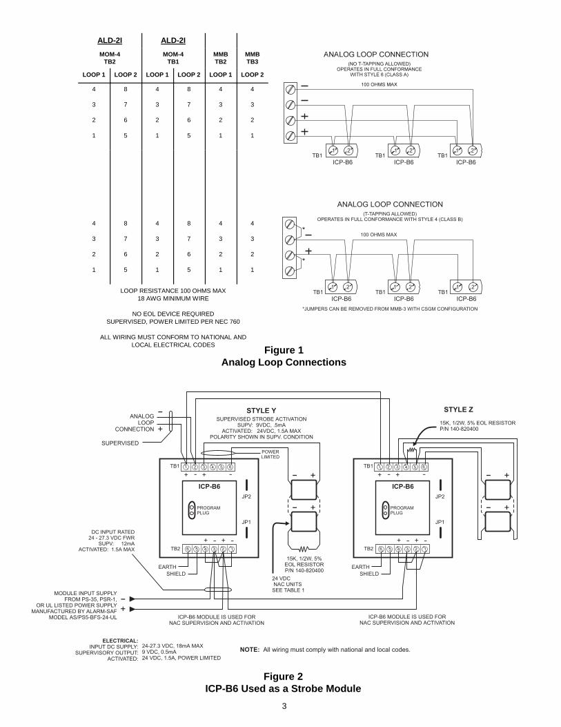
The ICP-B6 communicates with the MXLthrough its analog addressable loops. Theseloops are on either the MMB or on the optionalALD-2I module of the MOM-4. They may bewired for Class A (Style 6) or Class B (Style 4).Figure 1 shows both wiring types and theconnections to either the MMB or to theMOM-4 when the ALD-2I module is used. Thetable on the following page lists the maximumoutput currents allowed.
Fire Safety
P/N 315-095306-7
Siemens Building Technologies, Inc.8 Fernwood RoadFlorham Park, New Jersey 07932
Siemens Building Technologies, Ltd.2 Kenview BoulevardBrampton, Ontario L6T 5E4 CN
2
The ICP-B6 module can be used in fourdifferent ways:
1. Using the ICP-B6 as an NAC Module
This notification appliance application uses theprinciple of polarity reversal when there is analarm. Figure 2 shows the polarity connectionin a supervisory condition. When using theICP-B6 as a supervised NAC output modulewith notification appliance devices, cut jumperJP2. Refer to Figure 2 for additional connec-tion and jumper information, and to P/N 315-096363 for a list of compatible devices.
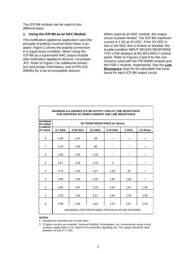
MAXIMUM ALLOWABLE ICP-B6 OUTPUT CIRCUIT LINE RESISTANCEFOR SPECIFIED DC RISER CURRENT AND LINE RESISTANCE
MAXIMUMDC RISERCURRENT(in Amps)
DC RISER RESISTANCE (in Ohms)
0.1 Ohm 0.25 Ohm 0.5 Ohm 0.75 Ohm 1 Ohm 1.5 Ohms
8 2.46 1.67 .33 -- -- --
7 2.53 1.83 .66 -- -- --
6 2.60 2.00 1.00 -- -- --
5 2.67 2.16 1.33 .5 -- --
4 2.73 2.33 1.67 1.00 .33 --
3 2.80 2.50 2.00 1.50 1.00 --
2 2.86 2.67 2.33 2.00 1.67 1.00
1 2.93 2.83 2.67 2.50 2.33 2.00
.5 2.96 2.92 2.83 2.75 2.67 2.50
MAXIMUM LOOP RESISTANCE FOR EACH ICP-B6 ON RISER
NOTES:1. Resistances specified are for both wires.2. If higher currents are required, Siemens Building Technologies, Inc. recommends using a local
auxiliary supply which is UL listed for fire protection signaling use. The supply should be ratedbetween 24 and 27.3 VDC.
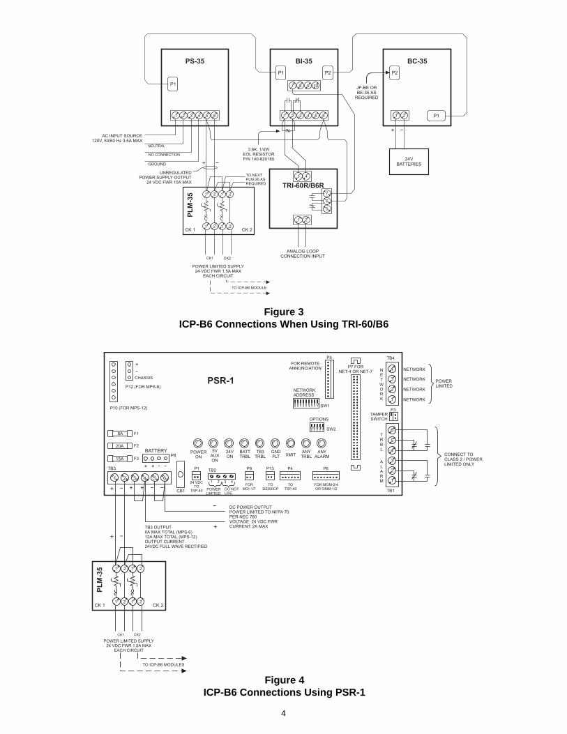
When used as an NAC module, the outputcircuit is power limited. The ICP-B6 maximumcurrent is 1.5A at 24 VDC. If the 24 VDC islost or the NAC line is broken or shorted, thetrouble condition INPUT DEVICE RESPONSETOO LOW displays at the MXL/MXLV controlpanel. Refer to Figures 3 and 4 for the con-nections used with the TRI-60/B6 module andthe PSR-1 module, respectively. See the LineResistance chart for the allowable line resis-tance for each ICP-B6 output circuit.
3
Figure 2ICP-B6 Used as a Strobe Module
Figure 1Analog Loop Connections
100 OHMS MAX
ANALOG LOOP CONNECTION(T-TAPPING ALLOWED)
OPERATES IN FULL CONFORMANCE WITH STYLE 4 (CLASS B)
*JUMPERS CAN BE REMOVED FROM MMB-3 WITH CSGM CONFIGURATION
*
*
TB1 TB1 TB1
ICP-B6 ICP-B6 ICP-B6
1 2 1 2 1 2
ALD-2I ALD-2I
MOM-4TB2
MOM-4TB1
MMBTB2
MMBTB3
LOOP 1 LOOP 2 LOOP 1 LOOP 2 LOOP 1 LOOP 2
4
3
2
1
8
7
6
5
4
3
2
1
8
7
6
5
4
3
2
1
4
3
2
1
4
3
2
1
8
7
6
5
4
3
2
1
8
7
6
5
4
3
2
1
4
3
2
1
LOOP RESISTANCE 100 OHMS MAX18 AWG MINIMUM WIRE
NO EOL DEVICE REQUIREDSUPERVISED, POWER LIMITED PER NEC 760
ALL WIRING MUST CONFORM TO NATIONAL ANDLOCAL ELECTRICAL CODES
4
Figure 4ICP-B6 Connections Using PSR-1
Figure 3ICP-B6 Connections When Using TRI-60/B6
5
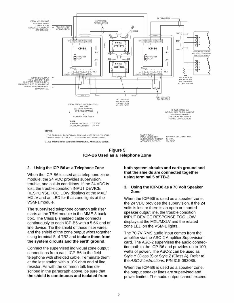
2. Using the ICP-B6 as a Telephone Zone
When the ICP-B6 is used as a telephone zonemodule, the 24 VDC provides supervision,trouble, and call-in conditions. If the 24 VDC islost, the trouble condition INPUT DEVICERESPONSE TOO LOW displays at the MXL/MXLV and an LED for that zone lights at theVSM-1 module.
The supervised telephone common talk riserstarts at the TBM module in the MME-3 back-box. The Class B shielded cable connectscontinuously to each ICP-B6 with a 5.6K end ofline device. Tie the shield of these riser wiresand the shield of the zone output wires togetherusing terminal 5 of TB2 and isolate them fromthe system circuits and the earth ground.
Connect the supervised individual zone outputconnections from each ICP-B6 to the fieldtelephone with shielded cable. Terminate themat the last station with a 10K ohm end of lineresistor. As with the common talk line de-scribed in the paragraph above, be sure thatthe shield is continuous and isolated from
Figure 5ICP-B6 Used as a Telephone Zone
both system circuits and earth ground andthat the shields are connected togetherusing terminal 5 of TB-2.
3. Using the ICP-B6 as a 70 Volt SpeakerZone
When the ICP-B6 is used as a speaker zone,the 24 VDC provides the supervision. If the 24volts is lost or there is an open or shortedspeaker output line, the trouble conditionINPUT DEVICE RESPONSE TOO LOWdisplays at the MXL/MXLV and the relatedzone LED on the VSM-1 lights.
The 70.7V RMS audio input comes from theamplifier via the ASC-2 Amplifier Supervisioncard. The ASC-2 supervises the audio connec-tion path to the ICP-B6 and provides up to 100watts of power. The ASC-2 can be used asStyle Y (Class B) or Style Z (Class A). Refer tothe ASC-2 Instructions, P/N 315-092085.
When the ICP-B6 is used as a speaker zone,the output speaker lines are supervised andpower limited. The audio output cannot exceed
6
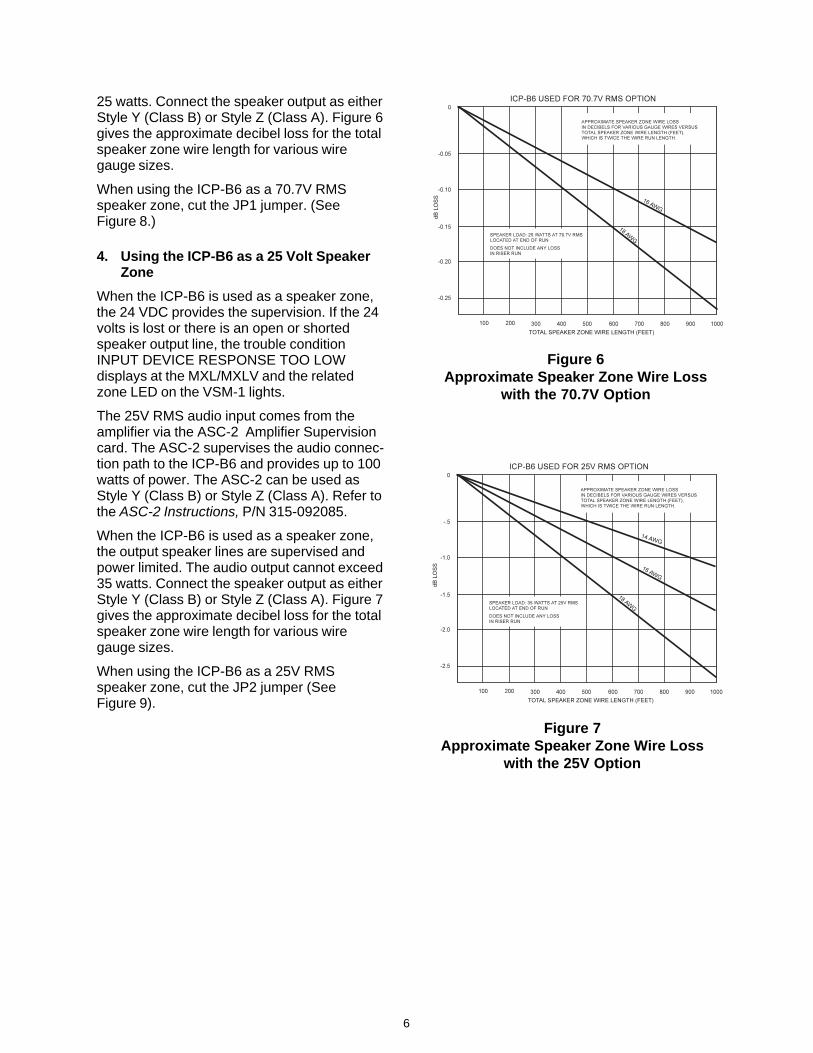
25 watts. Connect the speaker output as eitherStyle Y (Class B) or Style Z (Class A). Figure 6gives the approximate decibel loss for the totalspeaker zone wire length for various wiregauge sizes.
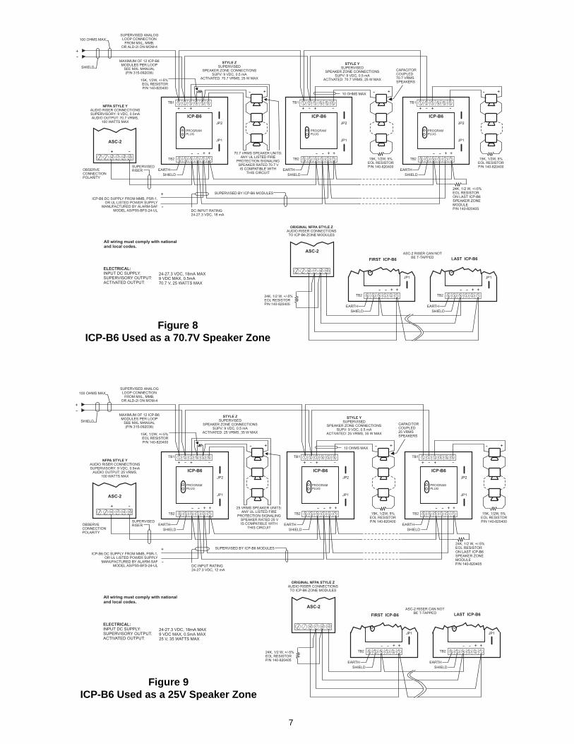
When using the ICP-B6 as a 70.7V RMSspeaker zone, cut the JP1 jumper. (SeeFigure 8.)
4. Using the ICP-B6 as a 25 Volt SpeakerZone
When the ICP-B6 is used as a speaker zone,the 24 VDC provides the supervision. If the 24volts is lost or there is an open or shortedspeaker output line, the trouble conditionINPUT DEVICE RESPONSE TOO LOWdisplays at the MXL/MXLV and the relatedzone LED on the VSM-1 lights.
The 25V RMS audio input comes from theamplifier via the ASC-2 Amplifier Supervisioncard. The ASC-2 supervises the audio connec-tion path to the ICP-B6 and provides up to 100watts of power. The ASC-2 can be used asStyle Y (Class B) or Style Z (Class A). Refer tothe ASC-2 Instructions, P/N 315-092085.
When the ICP-B6 is used as a speaker zone,the output speaker lines are supervised andpower limited. The audio output cannot exceed35 watts. Connect the speaker output as eitherStyle Y (Class B) or Style Z (Class A). Figure 7gives the approximate decibel loss for the totalspeaker zone wire length for various wiregauge sizes.
When using the ICP-B6 as a 25V RMSspeaker zone, cut the JP2 jumper (SeeFigure 9).
Figure 6Approximate Speaker Zone Wire Loss
with the 70.7V Option
Figure 7Approximate Speaker Zone Wire Loss
with the 25V Option
7
Figure 8ICP-B6 Used as a 70.7V Speaker Zone
Figure 9ICP-B6 Used as a 25V Speaker Zone
MOUNTING
(See Figure 10)
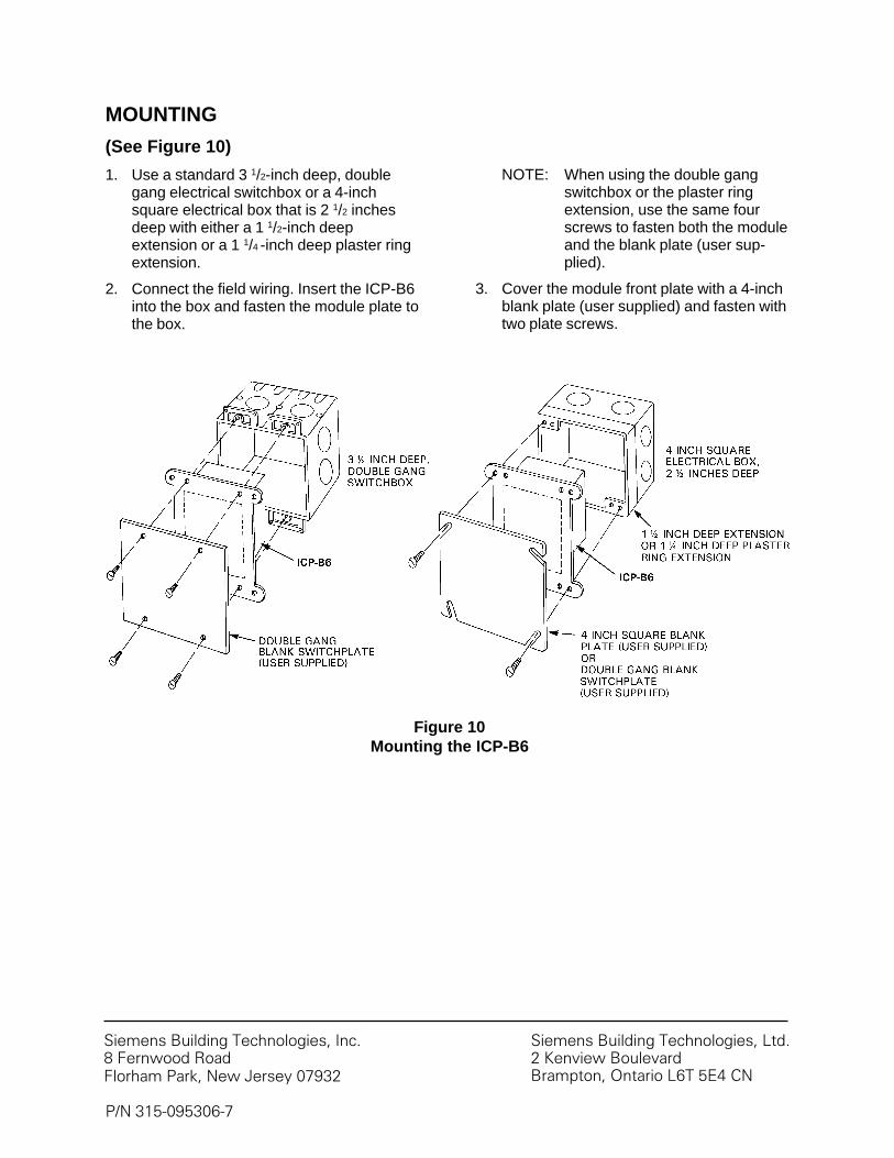
1. Use a standard 3 1/2-inch deep, doublegang electrical switchbox or a 4-inchsquare electrical box that is 2 1/2 inchesdeep with either a 1 1/2-inch deepextension or a 1 1/4 -inch deep plaster ringextension.
2. Connect the field wiring. Insert the ICP-B6into the box and fasten the module plate tothe box.
Figure 10Mounting the ICP-B6
NOTE: When using the double gangswitchbox or the plaster ringextension, use the same fourscrews to fasten both the moduleand the blank plate (user sup-plied).
3. Cover the module front plate with a 4-inchblank plate (user supplied) and fasten withtwo plate screws.
P/N 315-095306-7
Siemens Building Technologies, Inc.8 Fernwood RoadFlorham Park, New Jersey 07932
Siemens Building Technologies, Ltd.2 Kenview BoulevardBrampton, Ontario L6T 5E4 CN


![[SHIMADZU] 島津製作所 · cc-ms cv-aas, cv-afs, icp-oes, icp-ms, aas pbb/pbde cr(vl) pb/cd icp-oes. icp-ms icp-oes. icp-ms, icp-oes, icp-ms, cc-ms aas cv-aas aas : aas . - icp-oes](https://img.pdfslide.net/doc/110x75/602bef1d6551697710154f3f/shimadzu-eoe-cc-ms-cv-aas-cv-afs-icp-oes-icp-ms-aas-pbbpbde-crvl.jpg)