Embed Size (px)
Citation preview

,J Owner's Instruction Book
MODEL - J
rfKKOUrtcement Thi ' i i
B to rh< I nit' I :
one of th in An i hi
; rim
m] mot< thu - Clymcr
Re print i y
P L O Y 1) CI Y \1 I R u
At d A .
1268 ith Al\ I.os Ai I rnia

I In II mi ma
and m to
K>
H O R S E P O W E R S U P E R C H A R G E D I) i i S i B i K <i
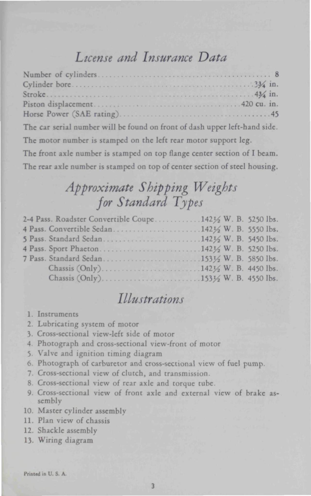
License and Insurance Data Number of cylinders 8 Cylinder bore . 1)4 i n-Stroke A^i in. Piston displacement . 420 cu. in.
Horse Power (SAE rating 45
The car serial number will be found on front of dash upper left-hand side.
The motor number is stamped on the left rear motor support leg.
The front axle number is stamped on top flange center section of I beam.
The rear axle number is stamped on top of center section of steel housing.
Approximate Shipping Weights for Standard Types
l-A Pass. Roadster Convertible Coupe \Al]/2 W. B. 5250 lbs. 4 Pass. Convertible Sedan 142>^ W. B. 5550 lbs. 5 Pass. Standard Sedan \Al]/2 W. B. 5450 lbs. 4 Pass. Sport Phaeton . 1 4 2 ^ W. B. 5250 lbs. 7 Pass. Standard Sedan 153>4 W. B. 5850 lbs.
Chassis (Only). 142^ W. B. 4450 lbs. Chassis (Only). 153K w B. 4550 lbs.
Illustrations 1. Instruments 2. Lubricating system of motor 3. Cross-sectional view-left side of motor 4 Photograph and cross-sectional view-front of motor 5 Valve and ignition timing diagram 6. Photograph of carburetor and cross-sectional view of fuel pump. 7. Cross-sectional view of clutch, and transm <>n. 8. Cross-sectional view of rear axle and torque tube. 9. Cross-sectional view of front axle and external view of brake as
sembly 10. Master cylinder assembly 11. Plan view of chassis 12. Shackle assembly 13- Wiring diagram
Printed in U. S. A.
3
Duesenberg I \ s l R I Ml N T A N D C O N I ROl
INSTRUMENTS AM) CONTROLS
(1 ) IGNITION SVU M H
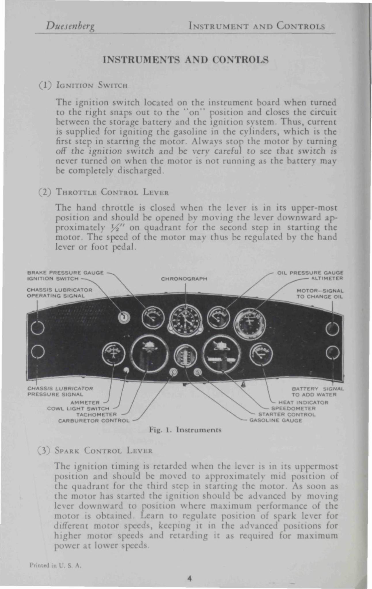
The ignition switch located on the instrument board when turned to the r ight snaps out to the " o n " \ tion and closes the circuit between the storage battery and the ignition system. Thus , current is supplied for igniting the g line in the cylinders, which is the first step in start ing the motor. Alw.i\s s top the motor by turning off the ignition switch and be very careful to see that switch never turnc n when the motor is not running as the batterv m.̂ be completely discharged.
) T M R O I I I I CONTROL LEVER
The hand throt t le is closed when the lever is in its upper-most position and should be opened by moving the lever downward approximately l/in on quadrant for the second step in s tar t ing the motor. The speed of the motor mav thus be regulated by the hand lever or foot pedal.
BRAKE PRESSURE GAUGE IGNITION SWITCH
CHASSIS LUBRICATOR OPERATING SIGNAL
OIL PRESSURE GAUGE ALTIMETER
MOTOR- SIGNAL TO CHANGE OIL
CHASSIS LUBRICATOR PRESSURE SIGNAL
AMMETER COWL LIGHT SWITCH
TACHOMETER CARBURETOR CONTROL
BATTERY SIGNAL TO ADD WATER
EAT INDICATOR SPEEDOMETER
STARTER CONTROL GASOLINE GAUGE
g. 1. Instruments
(3 ) SPARK ( ON I HOI LBVEB
The ignition tuning is retarded when the lever is in its Uppermost position j\)d should be moved to apptf tnatel) mid position the quadrant for the third Step in s tar t ing the motor U is the motor has started th ignition should be advanced by moving lever downward to i n where maximum jx't man< »i the motor is obtained Learn to I LllatC position ot spark lever tor different m o t - s, 1- ng it in the ad van* >r h i g h e i m o t o r s p e e d s d\u\ r e t a r d i n g it as r e q u i r e d t o r m a x i m u m p o w e r at l o w e r s|x*c
i A.

I N STftU M BNT \ N D C O N T R O L S Duesenberg
4 ) ACCELERAIOR P i DAL
The accelerator pedal performs the same function as the hand throttle lever and ordinarily is used in preference to the hand lever.
(5) CARBURETOR CONTROL
The carburetor control is to be used for enriching the carburetor mixture as required when the motor is cold. The fourth step in starting the motor is to pull the carburetor control out as far as possible until the m> r starts to fire, .id immediately return it gradually to its normal j n as the mi r warms up. Under extremely cold weather conditions it ma be necessary to leave the control pulle ut approxil W for a few minutes to give the correct carbureton until the water temperature is normal. The control should be pushed all the \ in to the instrument board as the warming up process is completed to prevent excessive oil dilution .ind resultant cvlinder wear.
(6) STAR I L
The engaging the starting motor is accomplished pulling the Control button I ited on instrument board out as far as p iblc and is the fifth ft 81 tarting the motor. The starter uld be engaged at in t en 15 s. dd not remain engage nger period i will discharge the battery rapidly If the m it start after two or three attcmj i immediate inve should be made t mine the trouble by checking the t wing items.
1 >hnc s u p p l v i I.
2 'line mixture too rich or lean. rburetor ma\ be choked excessively by leaving h control out t lonj
V Open throttle appri half v ri when mot! has ! i choked excessively
4 (heck g dine supply at I -uretor In removing h >n d r a i n pi in b o w l tr t h e f ron t on t h e It m a ) I ncc »vc »v\ I a bh Pan
' | I I Fiff. 3 I p rune the s\ stem b Itin p u m p In hand
V He sin witch nA check c if clc il terminals arc t ight the d i s t r ibu tor and igni t ion c t the
!t I
6 In cold the clutch | clin tc the load i o( I
me tc Is t, . h i t
k I
v

Ducsenberg I N S T R U M E N T A N D C O N T K U I
(7) CLUTCH PBDAL
The clutch pedal controls the o] n oi (he clutch and releases or disengages the motor to permit shifting and engaging the transmission gears. A clearance of 1" to IW' should be maintained between the return position of the pedal and the floor board at all times to insure proper clutch action. (See clutch). The foot should not be permitted to rest on the clutch pedal while d n \ i n g as this subjects the clutch parts to unnecessary wear.
(8 ) BRAKE PEDAL)
The foot brake pedal operates the 4 wheel hydraulic brakes commonly known as service brakes. Application and control of brakes is accomplished bv depressing the pedal in the conventional manner, the braking effect being directly proportional to amount of pressure exerted on the pedal
(9) GEAR SHIFT AND LIVI.R
The transmission is of the conventional three speeds forward with the standard universal gear shift. Due to the special design of the transmission a lightning shift of gears mav be made even at high motor speeds.
(10) LIGHT CONTROL 1 i R
The lighting switch is located at the base of the steering column and is operated bv the third control lever on top of steering column. Extreme position to the left is for cowl and tail lamps, next position to right all lights off and the two positions to the extreme right for h hts and tail light with the headlight beams deflected for one of ihe positions.
(11) H A N D BRAKE LEVER
The hand brake lever operating the emergency brake is to be used for locking car in position when parked Form the habit of locking the brake when the car is parked.
(12) WINDSHIELD WIPER
The windshield wiper is operated from the vacuum in the manifold and is controlled at the assembly b) I thumb screw.
(13) TACHOMI i i R
The tachometer is a revolution counter attached to the rear of one camshaft giving direct revolui per minute of motor speed.
in I S. A .

INSTRUMENT AND CONTROLS Duesenberg
(14 ) SPEEDOMI TER
The speedometer instrument gives the direct reading in miles per hour up to 150, together with total and trip mileage
(15) CHRONOGRAPH (Clock and Split Second Stop Watch)
The clock is an eight day instrument incorporating in its movements a split second watch bv the use of which actual developed speed can be figured from the specific time and distance covered.
(16) ALTIMETER ,
The altimeter records barometric pressure in inches of mercury together with altitude measured in feet. The graduated scale for altitude mav be shifted, thus allowing the scale to be set at zero with dial indicator whereby variations in altitude are indicated directly for different localities. By setting the altitude dial to the exact altitude of a given locality according to the corresponding barometer reading, weather conditions or changes may be approximated.
17) O I L PRESSURE GAUGE
The oil pressure gauge indicates the condition of the oil pressure system for the motor and gives the pressure reading in pounds per square inch. Form the habit of observing the oil gauge to see that it shows correct pressure at all times. If pressure should drop below normal, lack of oil or very thin oil mav be the reason.
18) GASOLINE GAUGE
The gasoline gauge indicates in gallons the amount of olme in the tank. This gauge is calibrated or set at the factory and should require no attention thru the lifetime of the car.
19) BRAKI I'I>I 1 HI GAUGE
The brake pressure gauge indicates the hydraulic pressure dcvel :d upon application of the brakes or in other W< - the work condition < »f the system. The brakes ordinarily require appr< matel) 200 pounds pressure for operation but the system is capable of developing 5<X) pounds pressure in enn ncies, thus a high factor of safety is maintained for breaking effect in controlling the Car.
20) A
The ammeter indicates the worl g condition of the electrical system or in other words the ran of charge or discharge of the battt The ammeter ! indicate a charging rati 10-12 amperes with all lights turned ol >i 2i 1 M. P. H
Pi Dt«J la U. S. A

Duesenberg I rauMi D C o
(21) Hi AT IN'D >R
The heat indicator j the temperature \ thi water cooling ii in degrees hrcnhcit The tnosl efficient operating
temperature is from ! 200 deg although in extremi or cold climates the temperature may run slightly hi lowei
(22) Ih N' i BOARD SIONAI LIGHTS
The green signal light at the right side marked "B when burning 1500 miles reminds you tl the battel
should be inspected and pure distilled wati Ided to bring the solution to within *.s" of top. The red signal light at the right side marked I h i " Ten burning approximately 750 miles indicates that the m >il b e changed. The red signal light at the left side when burning approximate! every ( ^0 miles indie s that the ch s lubricating mccham is operating and immediately afterward the green signal light should flash showing that c>11 is being delivered te> the vanoi shackle bearin Should the sectmd light fail t >pcrate cheek the oil supplv in ch.i lubric >r supply tanl I the right front side of the dash.
23) HOOD LOCK
To lock the hood pmpcrlv it iecess to place the lock control handle upright when dmpping h ! in position, then turn handle down in right hand direction, pushing cylinder of key lock "in ' lock control lever in down j Tool box and battery compartment le>cks operate in the same manner
(24) RADIATOR CAP
When re iving radiate>r cap care should be taken to unscrew cap far as l hie b« e lifting from shell, otherwise cap will not return te> its proper locking position when again installed.
Para^rjphf 2f-zg inc/uiite Ji ttHUti
Primed in U. 8 A.
8

OPERATION Duesenberg
OPERATION
In the dc [fling and building of this c.ir every effort has been made, to make it as complete s possible and to eliminate the many aim nces of periodic inspection and lubrication so essential to pr aging the li if the avi motorcar . In furthering this motive the manufacturing division has taken all p> ble precautions in buildin nd testing this car to eliminate various items of checking and preparation usually necessary upon receipt of the car at its destination When cars are shipped it will be necessarv to check the following items.
(30) PREPARING CAR FOR SERVICE
1. Remove spark plugs and insert approximately ]/2 "^ of cvlinder oil into each cvlinder.
2. Fill radiator with clean water lacity 7 gal ) In cold weather an anti-freeze solution should be used. See paragraph 73-
3- Fill gasoline tank (capacitv 26 gal.) 4. Be sure oil in crankcase is up to proper level which is in
dicated bv oil level gauge on left side of motor, (capacn 3 gal.) /
5- Check air pressure of tires, which should be 40 lbs. for front, 38 lbs. for rear.
6. Test batterv with hydrometer and see that all plates are covered with water.
7. Check all lights to see that they burn properly.
S\) RUN A N I W MI >R
The most critical period in the life of the m the first 1000 miles of operation Permanent injury or damage ma) result through the failure I observe the simple but fundanu \ laws of "working in" the new motor. During this initial period of operation, additional Cylinder lubric tion »uld be supplied bv adding one cjiiart of l ighter ' ngine oil to each ten gallon 'line used Sustained or continued high motor speeds are extremely detrimental until the motoi : ! the initial 1000 mil operation I ven after this mileage the moti aid never be r I, e ciall) when cold.
32) OPI I I \< , I ill ( \R
Opet ; the car, that is, starting the m <x, shifting ge COn troll in ind stopping the car is all accomplished m the C ventional in.inner with which all Operator re familiar It is
Printed in I \

Du ere ( h'l-.R \ i i : *
there narrate this simple lire t will c a list drivin Inch wc ti II as* in
operating the car ai
1 lTsc t he power the ID r and brakes n el) in COl t ro l l i ng the car
2 Drive v. the carburetor Contn ill the v ill against the dash at all til I when starting with the r cold Ki mixtures Cause r.< hit ion ami exc c cylinder wea
~S I the habi t d a n c i n g at t he in s t rumen t icl I he i n s t r u m e n t s indica te the o p e r a t i n g c litioi ' t he lubric ing , e lect r ical and c o o l i n g tcms Wat< lie oil gauge t e t h a t it ihi >rmal pre «t all t imes
4 >t r ide w i t h foot on the c lu t ch pedal or disen ,c clutch when i asting down steep y as these j cause carl rvicc replacements and expense.
5 Leave ignition On when coasting Failure & thi a l l h the cylinder walls I thin lubricat ing oil, while unburnt g. scd into the muffler D pr ucc great da hen ignited later as the switch turned " O n " .
6 Learn to regulate the i k con t ro l in r e l a t ion to mo t ' speed, d r i v i n g w i t h it in t he advance pos i t ion i h ig n pcc< ctarding it for ascending steep grades at low speeds.
13 I- cm W D L U I I
In listing the items which must necessarily be checked at different intervals wc have assumed that the i icr is th ughl imiliar with the attention nccc • iter in the cooling cm, water in the battery, gasoline, oil supply in the crankcasc, lig . tire pressure and the dail\ routine essential oca ful motor car operation However, descriptive details foi the above mentioned items will be found under their respective explanations in other
far <( thi ik
t is imperative that the follow ing items be checked verv thoroughly at intervals of 2500 and 5000 mil
A
10

C ) P I R \ T I O N Duf.setiberg
INSPECTION A N D LUBRICATION SCHEDULE
2500 MILES
( nASSIS LUBRICATION—Replenish oil supply in chassis lubricator supplv tank on r ight front of dash wi th Biiur special oil which may be obtained at our service stations or at Bijur Lubricating Co. , 250 W. 54th St., New York City.
5000 MILES
COMPRESSION—Check cylinder compression by turning motor wi th hand crank if compression is not uniform check valve clearance.
DISTRIBUTOR—Wipe distr ibutor head clean, inspect and adjust contact points.
TIMING—Check ignition t iming. FAN—Check fan belt adjustment.
SPARK PLUGS—Clean and adjust. GENERATOR—Inspect coupling, commuta tor , and brushes, and clean
them if necessary. Add 10-15 drops of oil to each bearing. GASOLINE STRAINER-- Remove and clean screens, etc. WATER P IMP—Inspec t water pump packing for leaks. Tighten packing
nut if necessarv
WHEELS—Align front wheels and pack front wheel bearings wi th a good grade of l ight cup grease similar to alemite.
ST i i RING G I \R Inspect for lost mot ion, pack gear wi th Whi tmores ' "65 lubricant, pack | ot pin bearings and tie rod joints wi th cup grease.
BRAKES—Adjust if necessarv Fill supply tank to wi th in ]/2" of top with genuine Lockheed brake fluid.
I LUTCH—Inspect for 1" to l j-4" free travel of clutch pedal and adjust if necc n
\x i i R i.AR - Inspect grease supply and bring to height of level plug with W h i t m o r e s " 0 " lubricant.
TRANSMISSION—Inspect grease supply and bring to height of level plug with W h i t m o r e s " 0 " lubricant.
BATTBEY— Remove terminals, clean, grease, and t ighten.
BODY BOLTS—Tighten
\ \ , SPRING ( -Tighten.
SHOCK ABSORMI I In ct and replenish oil supplv if necessary. CHASSIS LUBRICATOR—Remove signal box pump housing cap (J-1159)
Fig. 3 to clean felt I screen. Do not remove plugs in 1 er part of cap housing . i supj^l Ivcerin . retained in well at th
int to pr aire switch. Whitmore's lubl nt for transmission, rear axle and steering ge. n be obtaii at our service station or Whitmorc Manufacturing Co., Cleveland, Ohio .
Pr.nted ,n U. S A
II

Duesenberg E i
ENGINE
(34) 1 •• 1 ION' SYS! 1 M
Efficient and adequate lubrication is supplied with itivc pressure to all beat n d \\ ring surfaces of the motor The in explaining the oil circulation rem will be given In illustration No. 2 Von will note the location of the ! pump at the low< point in the oil sump where the oil is picked up being filtered and screened and then I to the main pressure Inn ' lin the entire system From the main pressure line oil is fir listribute to the main bearings, connecting rod bearings and piston pin which in turn lubricate Cylinder walls and piston rings From this point in the main hue a supply 1 lso sent directl > all camshaft bearings, accessory drive shafts and idler sprockets for t iming chain mechanism. The excess ot oil supplied to camshaft bearing is maintained .it the specific level in the camsl housings 1 provide a bath ol oil for all parts of the valve mechanism Ovcr-fl or drain holes in the camshaft h ing allow surplus oil ' drain back into crank case and is thus kept in circulation The oil filter located on the r ight side of the cylinder block is Constantly filtering and ren ing all forcii ttef in the oil suppl\ r.ikcn from the pressure line after pressure is supplied to all unit
(35) O I L P U M P
The oil pump is of the conventional gear type, having a capacity much greater than is actually necessat\ to suppl\ an abundance of pi ure at all times. The pump is driven DJ a vertical 1 ft through the le gears mounted on generator d n \ e shaft It mounted to the fust cross web of the cvlinder block and crank case bv two cap screws and is coupled to its vertical drive Lit by m |iiare sleeve coupling The mam pressure line fi pump to cylinder block may be dis embled after loosening tube packing 1< nut In order to remove oil pump it first necessarv to remove the oil pan and sump and then detach from its mountin
}6) On PRI 1
The I prcssui idjustment is located on the lower left hand side of the Cylinder block 1 in front of the 1 float -c indicator By changing t in- adjustment screw and turning in a clockwise directn pressure will be inCl I .i^ indicated on the gauge-on the instrument board Turning n clockwise el 1 reduces the p -ure accordingly I his adjusting screw is connects bv a flexible cable I 1 the relief \ a I ••. lecvc in the oil pump, consequently when the ad lusting \ \n the bloc k is chai >u a r e n h ii i n g o r dcc i spr i l tl re a t t h e o i l p u m p T h e s u r p l u s o i l I n - p a s s e d by t h e relief v a l v e is d i s c h r c c t l v b a c k in t h e o i l SUppl)
I
12

E N G I N i Duesenberg
l u ~1TT if
; 2. L u b r i c a t i n g Sys tem of M<>f.r
The correct oil pi ure to be maintained sit all tim approximate!) 2 to 10 pounds for low idlil ccels and approxunatel\
iund for every mile |X.T hour with a i urn of 80 to 100 pound' r high speed »n It i ry< A that this correct pressure is maintained til times.
•~ I In. Si AND Fl lAT G
The< hccrankca 12 quart thi ted b o indi( ;e located at the lower nt left h.nnl side Or the cvlinder bl
Printf.1 in l \ S. A.
13

! I! • *
I | roti S I \ leu I i fi Side d Mo*
14

Duesenberg NGINE
Fig. }. PARTS DESCRIPTION
101 103 104 105 107 108 109 110
121
124 130 138 140 146 150
154 160 162
166 167 171
176
• -
182
187
zoa 204
101 302 303 306
•
310 311 312 313 314 315 316 317 318
320 321 323 324
326 327 328 329
401
460 461
m a i n b e a r i n g c a p iter m a i n b e a r i n g cap
R e a r m a i n b e a m ip F r o n t m a m b e a r i n g bu-hiruv
te r m a i n b e a r i n g bushing* R e a r m a i n b e a r i n g bush ing Main B e a r i n g S t u d Main b e a r i n g s tud n R e a r m a i n b e a r i n g oil r e t a i n e r R e a r m a i n b e a r i n g oil r e t a i n e r Ga
inder w a t e r p l a t e screw Main b e a r i n g b u s h i n g r e t a i n e r s c r e w Chain case c a p s h o r t s c r e w Oil filler ben!
a r m a i n b e a r i n g oil r e t a i n e r sc rew e a t h e r body rather body G a s k e t
B r e a t h e r body c a p • a t h e r body cap screw
Oil g a u g e float b r a c k e t s c r e w flexible shaf t flexible sha f t lower end float b r a c k e t bu>hing ind ica to r face p l a t e i nd ica to r nut
va lve body
s p r i n g s t e m col lar
lift p in flex shaf t u p p e r end flex shaf t lower end
Oil Oil Oil Oil Oil Oil Oil Oil
Oil Oil Oil Oil
n u t Oil Oil Oil Oil
ga
g a u g e g a u g e g a u g e g a u g e d r a i n d r a i n d r a i n d r a i n dra d r a i n d r a i n drain
va lve va lve va lve
va lve va lve va lve
flex sha f t p a c k i n g
d r a i n valve lever d r a i n valve lever sc rew pan f ron t p a c k i n g p a n r e a r p a c k i n g
t h r u s t washi e p lug
h«>le p lug gask 'I bushin
r<> rod rod rod
c a p bolt
bolt n u t
lock ng r i n g
C r a n k s h a f t C r a n k s h a f t C r a n k s h a f t C r a n k s h a f t C o n n e c t i n g C o n n e c t i n g C o n n e c t i n g C o n n e c t i n g C o n n e c t i n g P i s t o n P i s t o n p in P i s t o n p in P i s t o n compres sb Pis ton oil r i n g
y-wheel F ly -whee l r i n g g e a r
v-w heel bol t F l y - w h ' < I h o u s i n g F ly-whee l cover p l a t e
g j a w j a w j a w j a w j aw j a w j a w
/ -wheel ho ip Cy l inde r head g a s k e t C a m s h a f t f ron t g c a p C a m s h a f t i n t e r be g cup E x h a u s t c a m s h a f t e e n t e r b e a r i n g cap C a m s h a f t f ron t ing b u s h i n g C a m s h a f t i n t e r bea r ing C a m s h a f t r e a r I- i r i n g b u s h i n g I n t a k e c a m f ron t cover I n t a k e cam r e a r cover Intake cam r e a r cover gaske t
S t a r ' S t a r t mg St a r t it
a r t i n g S t a r t n
es p a c k i n g
c a s k e t s p r i n g
p r i n g r« p in
screw
J- 467 J- 468 J- 469 J- 4 J- 474 J- 475
J-J-J-J-J-J-J-J-J-J-J-J-J-J-J-J. J-J-J-J-J-J-
476 I 184 185
190 551
oof.
556 558 559 561 562
I i 659 660 661
J- 665 J- 680 J- it J- 682 J- f, J- 684 J- 6 J- 688 J-J- 691 J- 6! J- 61 J- 699 J- 7 J- 7 J- 859 J. B80 J- B J- -J- H86 J- 9* J- *«
J-1012 J - 1 J 0 0 J-12 J - l l l 1 J-111H J-1124 J-1127
J - l l
J - l l J - l I J - l l J - l l
J-1507 J-161
011S 0] oi I 0125 ( i i
0] I I !
Cam Cam Cam Cam Cam
>m W C a m Cam
cover e r . • i
cover cover co\
r ea r c a p g a s k e t f ront a n d c e n t e r p a c k i n g r e a r p a c k i n g
l a r g e ham] nu t n u t n u t
l a r g e haml smal l h a n d
a s sembly s t u d r e t a i n e r
r e t a i n e r ,i s e m b l y
cover s m a l l h a n d nu t over sma l l h a n d nu t
C a m s h a f t b e a r i n g c a p dowel C r a n k s h a f t p lug Ta« ho tne te r d r ive plug T a c h o m e t e r d r i ve cover C r a n k s h a f t s p r o c k e t L o w e r a d j u s t i n g sp rocke t a s s e m b l \ Ac< ory s h a f t Sprocke t T r a n s f e r s p r o c k e t a s sembly U p p * r a d j u s t i n g s p r o c k e t a s sembly
>wer c h a i n U p p e r c h a i n C r a n k s h a f t s p r o c k e t lock w a s h e r Gen . sha f t s p r o c k e t oil s l i nge r Camshi i iprot c a p s c r e w T r a n f< r s p r o c k e t a s sembly s tud A d j u s t i n g s p r o c k e t a s s e m b l y s tud Gen ' o u p l i n g disc sc rew D i s t r i b u t o r b a s e G e n e r a t o r d r i ve shaf t f ron t b e a r i n g G e n e r a t o r d r ive shaf t r ea r b e a r i n g b u s h i n g D i s t r i b u t o r Gen. sha f t Gen . d r ive
c a p Hcrew con t ro l -haf t
ir hous ing shaf t -haf t t h r u s t w a s h e r
s h a f t r e a r oil s l i n g e r shaf t r e a r hous ing c a p c o u p l i n g shaf t c o u p l i n g sha f t end c o u p l i n g s h a f t pilot
Gen. d r ive Gen . d r i ve Gen. d r i ve Gen. d n Gen . d r ive Gen . d r i v e G e n e r a t o r coup l ing G e n e r a t o r s t r a p G e n e r a t o r s t r a p s t u d G e n e r a t o r s t r a p n u t F a n a s s e m b l y F a n d r i ve pul ley lock w a s h e r <M| p u m p body to cy l inde r screw Relief va lve Relief va lve s p r i n g Relief valve flexible shaf t a s sembly Relief valve flexible s h a f t lower e n d [ n t a k t m a n i f o l d core hole p lug I n t a k e man i fo ld c o r e bole p l u g g a s k e t
ase v e n t i l a t o r flan; Fue l p u m p a s sembly
Lsolin* filter bowl I p u m p d r ive h o u s i n g cover
s h a f t h a n d l e bou ing ' oi tr erev
cover ga id n
p u m p hous ing p u m p hous ing cap
cap p u m p guide M-rew c a r g a s k e t
s p r i n g
Fu< Fuel pun S igna l bOX
al gna l gna l
ignal g n a l
S i g n a l tfnal
box
box box box box
b<»x p u m p a s s e m b l y ' u t i b pilot b e a r i n g 1 i tch pilot b e a r i n g r e t a i n e r Hex . head c a p sc rew F l a t head m a c h i n e sc rew P l a i n c u t w a s h e r 'I u p p e r pin w I r u n key v\ oodruff key I [ex head • ap crew
Pn A
15

I N I / > / / herv
-. I i i I I . i
T h i s quan t i of oil >uld be m.uni I in the cranke at all t im !, to be rep laced , after 750 miles as indie
the ;nal l i gh t on the lent ird 11 r flush m r with I enc or flushing oil as it
imi >letor< irtion of this fluid which will re m m the different rcserv Ten dr< of light engine oil mid be
generator shaft bean: t the nc time motor oil is changed The 1 filter on the right h the cylinder block contaii a mesh c red c -,c, which rci ad re ill ;c and foreign material found in the I. This filter should be disa sembled and clc aghlv with 0 mile id after 20,000 miles it I abl thi artndgc. The filter m becomplctelv nbh cr removing large hex nut on top
\ 9 ) O I L S P I X I VTIONS
It is not possible t ise the ne grade of engine oil f all | of the year execj a cxtremclv mild climates An I heavy" grade of oil should be used for the warm l with specification illows:
Viscosity at 100° F 1421 Saybolt \ i at 210° F 105 S bolt Flash 455° I Cold Test lo° P
This grade of oil n be obtained in many national!} lvcrtis< bran> ind is classified in most t or S A I specification ' ; inly the very best oil obt able. 1 the winter months the next lightest grade should be used which I 50 or where the cold weather is cxtremclv s< \ I 40 oil may be desirable
40 C'.R INK
The crankshaft I f the vital factors contributing to the smooth and uniform flow of power at all S] The shaft, machini
.ill surfaces, is balance within hun Ith >unc nd then given ainic balance with th limits
for all motor s| Further than th ml irtially filled with mercury are ati to the cheek he shaft, tl shift; if the mercui in the tul thus eliminating e i tl shgh tion in power tmpul Tin haft of chromc-nickel-mangane I has < it connecting roel throw five n lals 0 mple \tre Iv large connecting cheek ; a positive alignment and i litv uin1 ill lo The Center f m n e c t i n g rod bear ings are in 01 p lan , at r i g h t angle d< i t he t w o end pairs Oil suppl ied at t h e main bea r ing |OUi t r a n s m i t t e d to the connec t ing rod bea r ings t h r o u g h holes elnlled in the cheek f the
ft, where an enlarged chamber pocl that mav I present in the oil and thus giv dutcly clean oil to the bearing
I'r , A
' 16

Duesenberg ENGINE
( 4 1 ) M A I N HI \KI NGS
Five main bearings wi th a large diameter of 2}^" lined with "Mogul Genuine" bearing metal support the crankshaft. Main bearings are fitted wi th 0015" clearance to allow a full cushion of oil for supporting the shaft. End thrust is taken at the front main bearing and held to .0015" limit No shims are provided for t ightening bearings as this operation should not be necessai in the life of the motor. However bearings ma) be tightened b\ removing each lower half using very fine emery cloth on a surface plate to remove desired amount of metal from the top faces of cap He sure to tighten I ring cap nuts securely
42) CON riNG RODS
The connecting rods made of duralumin using a steel CAP, provide a very light and strong unit, adding great I v to the efficiency of the engine. Rod bearings wi th a large diameter of 2-7 16" are lined with ' M o g u l Genuine ' bearing I and fitted with .0015"— .002" clearance. One webb of the I-beam section of the rod is gun-drilled to pi le oil | .sure to piston pin bushin . . shim are provided for i ing I ring IS the shims will not allow correct alignment of lower half wi th upper half of rod. Also it ordinarily is unnec tighten bearings in the li! f the motor but mav be accomplished in the same manner as explained in the previous paragraph for the in bearing He sure cap nuts at
loreel sec u re I \
H PISTON, P , RiN
The pi ns useel are made ol \ tremelv light aluminum alloy, the ele w h i c h a l l o w s a n d m a n u a l u n i f o r m e x p a n s i o n of t h si ith the C\IIIKICT walls for all m >r temperatures The skirt of the piston is separat from tfie head on th ireumh thus causing heal to be dissipated from the head of the pistO into the pin I and connccti rods I skirt has re d Onl) lint of heat norinallv transmitted by other conventional I fin with maintain th tin i main thousand miles of operation Fout piston rin d, tin >n wid< l o u b l dut) oil rcgulatin j I wide Km luted with 014 to A ho l low pis ton pin 1 1 I <V in d ian in the p is ton pi Ol c o n n e c t i n g | bush A\)A is locked in the p is ton b\ means of two p i ings at h end. 1 a just dec in in rhc bushii nd a slight iving fit in the piston
M BLOCK ( « IN k>
Th. lit e\ lin< n bloc w ith halt ol I h In; I h< ma A block
I \
17

E N G I N I Duesenb{ rg
is chrome-nickel ting, giving long v life lindcr b. All cylinder rels jacketed for the full circumference and the entire length Alumin r plates enclose the water jack >n both \ the block i iteccion to casting in case < meeting rod and piston assemblies n be no\ •• m the botl he >tating crankshaft luring the Of i
4<, < ); i BASI Lov HAI
The oil base i aluminum casting with long deep e ling ! OH the underneath Tw mount i (he left side the cylinder block idc additii I venti ling the oil supply in the crank \ baffle | m and line mesh ^crce height '/' covers the entire i the oil base giving a large surface fol removing foreign m rial in oil supply bcfoi ent( g the | It is not nee tOV< i -r cleaning when changini il, but she>uld be IC if oil b is removed at anv time To remove crank e n i necessary to remi , sere ancrn ig mud pans on top flange, 31 w% underneath anchoring ton flange to cylinder block, y caj crews underneath bolting re.it tlange ing A large circular plate is I d in the mi which n be rc-moved fe>r inspection of the oil pump, oil drain \ a b >nd oil tl gauge.
(46) FLY win i L
The flywheel is a steel fe>rging 14-15 16" in diameter completely machined em all surfaces hardened el ring gear with 119 teeth i 'irunk on the flywheel to engage with the irting m >r. Twelve 7 16" bolts and nuts uncvcnl) accd anchor flywheel crankshaft tlange so that it is imj ibl< mble the flywheel to the shaft in the wmng ition Markings on the flywheel indicate top cent for both No 1 .mi] m this manner I and 8, TOT Marl ippear b nd after center to give rel for ignition and valve timing which i iven in inches and degre b' fter center
47) CYLINDI I Hi \i>
The cylinder head is a chrome nickel casting carrying the valve mechanism and overhead camshal lirccth above thi alves The head is removable and may be detached m the cylinder block by removing upper chain cover, chain driving camshafts, Cylinder head stud nuts ace etc , as explai I under irbon ai Valvi Water p age icircle valv< irk plug ch.imbe on all sides, giving ] and abundant Cooli for all parts even for the most vcre mditions I w.> intake tnd two exhaust valves are used I men d power bv permitting a full charge
A.
18
Duesenberg E N G I N E
of fresh gas to enter the combustion chamber and then expelling it through the large area thus eliminating the necessity of excessive heat beini issed over single valves, as takes place in conventional cvlinder combustion design.
48) VALVI \1 IANISM
The valves are mounted at 35 degree angles to vertical center line of cvlinder head with camshaft mounted directly above and operating valves through sleeve tappet between shaft and valve. Excess oil supplied to camshaft bearings under pressure is trapped in the camshaft housing and maintained at a level above tappets to provide an oil bath for valve tappets, guides and contact of tappet against cam. An oil va, thus passes through tappet assembly t lubricate valve stem and guide beneath. Consequently a very quiet and trouble-free valve operation is maintained at all times.
49) VALVES
Intake valves are made of chrome-nickel steel, with \]/2" diameter head, 11 32" diameter stem and 30 degree seat. Exhaust valves are made of silichrome steel with 1-7 16" diameter head, 11 32" diameter stem and 30 degree seat
(50) VALV TAP s AND TAPPET GUIDES
Valve tappet guides are a just free fit into cylinder head and anchored in pairs bv means of two clamps each. A clearance fit of .0015 inches between tappet and guide is maintained at all times using a special steel for both units.
51) VALVI ADJUSIMI.ISJT
Adjustment of valves is provided by adjusting nut (J-420, Fig 3 ljusting sleeve J-421, Fig I This adjusting nut assembly
makes cont between end Of valve stem and underneath surfac of tappei Shim f the desired thickness are assembled between adjusting nut and sleeve to give the required clearance of 022 between the tappet and camshaft An ordinary thickness or feeler gauge mav be used for checking clearance between tappet
I heel of cam, while 1-inch micrometers will be needed for checking thicknes el justing nut t< ive correct clearance b
lition or removal of shim it In ler to perform the opt ti ting , it i firs icce remove cam It c< , upper chain cover, U| chain, distributor, camshaft
etc , to give ace [ " ig nui lirectlv on top of valves ! ure t ippe ance with feeler gauge for h v.dve I mo' msl and make pencil 11 scttii il abh hai ut th the dimensii id thus obtaii ct dea rano
19
ENGII h/e i l>tr%
i i
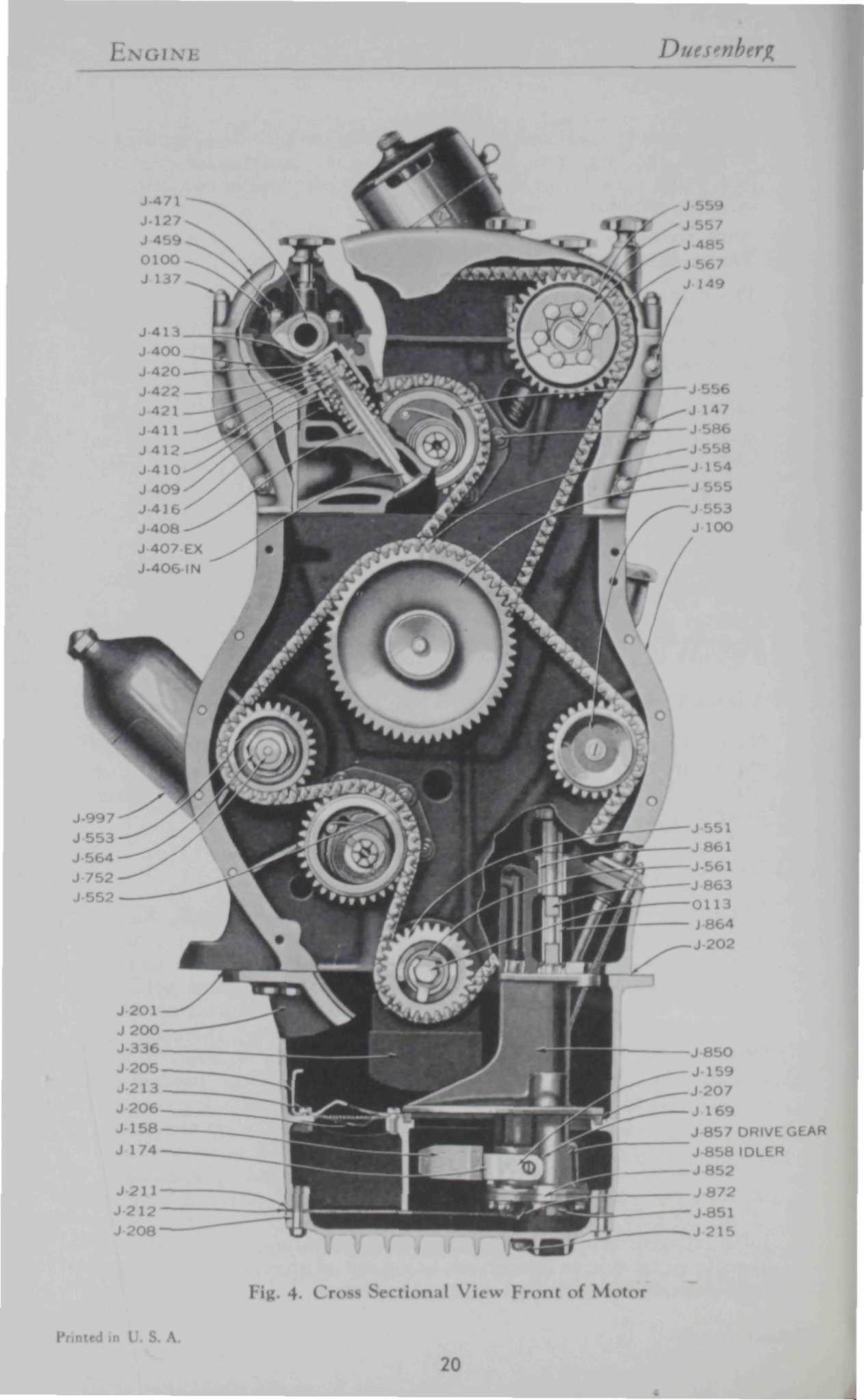
g. 4- Cross tional \ \ Front of Motor
20

Duesenberg ENGINE
Fiu 4. PARTS DESCRIPTION
J -J -J -J -
137
J - 149
J -.1-J -J -. ! -
J -J -J -J -J -J -J -J -J -J -J -J -.1-J -J -J -J -.1-J -J -J -J -J -
174
201 202
211
336
409 4 in 411 412
4IH
lock a in case
i case c a p long n case upp< (Un
s c r e w n case upper lnn»r
r«.-w
• a t h e r body c a p screw k-a a t k-aiik't- brack
l g a u g e bevel Rear it a s s . m l
I pan Li R l l gaak<
I I I
to oil
isembly
• r \v long --tud 1 haf t sma l l i ht
1 ad I n t a k e v a h
it va lve
I n n e r Valve sp> rintf
i ' r.
•
I <n n
i n
p a n
m m m
Valv .
Valvi-Va lve
J -J -J -.1-J -.1-J -J -J -.1-J -J -J -J -J -.1-J -
J -J -.1-J -J -.1-J -J -J -J -J -J -J -J -
V a l v e i i m p
120 121
I 171
1
76
SI
0 1 -( .113
I V€ a«I j • i K nu t V a l v e I eeve Va lve in a d j u s t i n g sh im i
ft C a m s h a f t
a d j u s t i n g sprock t assemfa A< i * f t T r . mbly
adj I aasemfa rock<
i n i n
' lock » er (Va t ft spi lock nut Cii p s e n \«l a s sembly i t ud Wate i p u m p d haf t
td
pum] r g a s k e t a r
ir 1 :tft bush ing
1 t ft imp dl :*ft I linK
-h;ift
Oil
Oil ft 1> hintf re \\i\*e nu t
m p p r e s s u r e t u b e i> •• k o m p p r e s s u r e tul her
n i t e r Hssomb P la in hex - 24 Hex head cs l »
>2) VALVI C U M . :
The valve gui< arc special steel with press fit in cylinder head and a ream clearance tit of .001" for vah rem
*)"} VALS I S P R I N R I i M N I I
The valve | rings arc made «>f the I grade electric turn reel lilable; tw prings being used each valve and embled in
the convent! I manner using aeroplane type retaining washer locks to anchor retaining washer t< alve The retaining washer lock in tw< -Ives with outside tapered diameter resting in retainer V I ( lamping valve I the three ring groove
54) CA M I I hi M(| N1
The c niide of special >rtcd bv h\ hearings each 1 ' x" in diameter The I re lined with \ b gul ( nine" bean \u\ given nice lit ol L5 For camshaft journals End thrust taken t bearing man tamed at \ alve lift tor intake shaft is ^ **> ' )T exhaust
(55 I TIMI ( MAIM
Two endli it timing cl ith aut ic adjustment are used i Irive < w^\ ace hafl he lower chain p number J 558, I 3, 2 inches wide .in<\ appn itelv A
in I \
21
ENOI ; Duesenbt
inches in length with pitch drivel the gei fl water puni, ft, and transfer sprocket lor upper I n I lie automatic idler sprocket part number J-552, ' ig '>, retains the correct nt of tc >n on the chain at all time f il spring loaded huh and automat ic.ill\ adju the ch.im lor v The chain m.i\ he re t removing I in cover then dii mbling automatic idler lined under "Valve Timing' I »r the upper chain The lower chain mav he assembled in mesh for any posn i all sprockei
The upper chain, J-559, Fig 3, 1-11 16 mcl wide and approximately 52 inches in length with a pitch drives the t w camsh. from driven transfei I i hain An automatic idler J-556, Fig V tintains the correct tension which automatically comp< ttcs I >r v r. Oil pre ire supplied to idl< sprockets provide an oil hath for the complete cl I mech in To reim per chain t dis -ruble ting idler sprocket Remove cotter pin and plain w ier then witl v drive thin tool pr\ ard the sprocket hushing and spring a mhl\ J-574 until spring [most ready to slip out notch m mount ing shaft w i t h special tool pari > J-7 ten ing from notch and pull forward, then allowing the spring to unwim The idler sprocket ma) then he removed and the chain lifted ofl camshaft sprocket The lower chain may DC removed in the same manner after removing covers, etc In assembling upper chain to sprockets as when setting the valve timing hi ire to k chain taut in the pull direction at all times mblc idler sprocket
1 hushing using special tool to center spring and hushing scmhlv setting spring with twelve notches or two complete turn Turn motor with starter t How chain lume normal position and reset the ten n on spring to 9 notches or \]/2 turns.
,6; VALVI. TlMll
The valve timing mav he checked or reset iutlined in Fig. 5 In order to check timing first rem< inspection plate on top of flywheel, exhaust cam cover and front intake cam cover. Rotate crankshaft with prv-har through inspection plate hole again teeth of flywheel ring gear until crankshaft i n top center for Numhcr 1 an hnders determined hv markings on flywheel follow 1 I move distributor h id with spark control AAXA 1 note if the mam rotor arm is in correct iition to In Ier plan in lag ^ If its position is incorrect rotate nkshaft I mp! ilution to bring di tributor in firing position for number S cvlinder when No 1 m-tak chaust Can re downw lllustrai With bar through inspection hole in flywheel h ing rotate crankshaft back imatel inches on the flywheel and rotate forward until intal 1 irting to Open. The
1 center line on the flywheel should be )usr ahead of center lii flywh housii
Pi \
22

Duesenberg ENGINE
A st raddle c l a m p shou ld be used to c l a m p and t w i s t tappet J-413 as the c rankshaf t is ro ta ted to de termine the exact t i m e w h e n the camshaf t ( facts to open va lve. T u r n f l ywhee l ahead and w i t h c l amp on exhaust valve tappet J-4M the va lve shou ld close, or the tappet release, w h e n N o 1 and 8 center l ine is ] | ist center
l ine of flv whee l hous ing . The va lve clearance shou ld he 0 2 3 " t o .025" to g ive th is t i m i n g T o change or set t i m i n g i t is necessarv to remove upper t i m i n g cha in cover , r .n! i . i tor , fan , and disassemble cha in mechanism as i lamed under " T i m i n g C h a i n " . In reassembl ing cha in A\)A sprockets to g ive the correct t i m i n g it w i l l be necessarv to remove the six 5 /16" Capscrews and sh i f t t i m i n g cha in sprocket-, on each camshaf t in order to ob ta i n the correct t i m i n g w i t h respect to c ranksha f t . A b lock of w o o d shou ld be edged between cha in on transfer Sprocket and case to prevent cha in e l ropping d o w n At th i s lowest po in t The flv whee l shou ld be set w i t h i n of the respect ive po in ts for se t t ing camshaf t to a l l o w for the slack in the cha in The cha in shou ld be kept taut at a l l t imes in assembl ing W h e n va lve t i m i n g is changed i t i b\ ious tha t the i g n i t i o n t i m i n g shou ld be c h e c L and set as exp la ined under ' " I g n i t i o n T i m i n g '
57; V A L V I G R I N I M M I
Procedure for g r i n d i n g valves
1 Remove h o o d .
2. Remove l iatOl Remove brace ro i ls , r ad ia to r h< m-nect ions, ho ld d o w n nu ts , A\U\ l i f t r ad ia to r d i rec t l y up-v Is;. *
3 Remove fan Remove eccentr ic l o c k i n g bo l t in cover and pu l l fan f o r w a r d f r om its m o u n t i n g
4 Re ive C hah covers Upper cha in Cover, d i s t r i b u t o r I and c o n t r o l , spark plugs A\IA w i res , tachometer cable at
rear of i ha f t , heat indie >r l ine and b u l b in wa te r m a n i f o l d , w r m a n i f o l d , fiaust m a n i f o l d , in ta l i I Id , ca rbure to r , exhaust heat connect ion act* cv l inder b l o c k , etc
5 D mblc upper cha in as exp la ined under " l i m i n g ( h a m ' '
Remove cy l i nde r h ! stud i o r n ' nu i
7 Assemble special c bo l ts and hooks to spark p lug hob to pr< for hoist in h f t i n Under h
8 Af ter head is removed and pi 3 I on bench imsha f t , valve tappets , spr ings AWA \ A \ ma) be removed sp il too l part \ o I tuld be used in d< ing v a I
9 \ n i m p i o d rack shou ld be m. ta| a I iust i nut ul valves
mblc th in th ! l oca t i on to
Priw. i \
23

E N G I N E Duesenberg
SYNCHRONIZING GAUGE
ROTATION
INT. No. 8 ' A
ROTATION
EXH. No. 1 X
SPARK RET. i
AMPS. DROP
SPARK ADV.
DE TAIL
L I G H T S OFF
THROT. CL.
THROT. OP.
BRIGHT TAIL
DIM TAIL
1 & 8 lO-p-W-5'
EX. CL IN. OP.
ROTATION
4-4 & 5
CL.
2 & 7
I in. 5. Valve and Ignition Timing I diagram
Printed in 1 S. A.
24

Duesenberg F u E l SYSTE M
do this will cause a great amount of additional work in sett ing valve clearances.
10. In grinding valves, seats should not be given a greater wid th than 3 }l"• In case it is necessarv to grind seats, to a greater width in order to obtain a full bearing for the complete circumference a valve seat sweeping tool should be used to narrow the seats.
11. Reassemble valves, springs, keepers, tappet valves, adjusting nuts and camshafts. Be sure tappet guide clamps and all camshaft bearing caps are t ight . Rotate camshafts and with feeler g.iuge blades obtain actual clearance between cams and tappets Remove camshafts, tappets and tappet ad lusting nuts and wi th shims of varying thickness change-length of adjusting nut to the required dimension to give .023" to .025" clearance. One inch micrometers must necessanlv be used to check length of adjusting nut before and after removing shims.
12 Assemble cvlinder head and units to motor being sure to set valve and ignition t iming as illustrated in Fig 5 and described under their respective headings.
58) ( UIBON Oi I'osi r
Ord inan lv it is not nee 11 \ to clean out carbon and grind valves under 15,000 to 25,000 miles, provided a clean burning high compression gas is used at all times Oil changes must be made recommended to eliminate crankcase dilutii >n and «. arbi in deposits. Carbon can only be removed In scraping after cylinder head is removed as describeel under '"Grinding Valves" .
F U E L S V S T K M
G (line supplied to the carburetor from the 26 gallon tank at the rear bv mean t a mechanical I I bellows pump in conjunct!' HI with an electric booster pump. A gasoline chamois strainer bow I is placed just ahead of the pump to trap dirt and scdi I it which has accumulated in the A positive SUppl >J clean gas is thus maintained at the carburetor under all Operating Conditions.
59 ( i< 1 1 O R
The a! Schcbler carburetor I duplex air metering tvpe supplying the two sei itc manifold chambers from ^nc fuel chambi
»wl The carburetor has two l 1 , " throat openings wi th adjustments foi ich me similar to twi iretoi I thus mi mg the ga mixture se ly to No 3, 4, 5, < nd 1, 2, 7, 8 cylinders as is readily d< I b\ observing the intake manifold
I HooK-1 Fp
The control tubing is fasti I securel) in the clamp and screw
A.
25

F U E L SYSTEM Duesenberg
N P H
SAME A D J U S T M E N T S FRONT AND REAR
j 1226 J 1230 J 1231
J 124 J-l 1 10 J 1 1 13 J l l l l
w J 1 108 J 1 105
'. 6. C a r b u r e t o r and l t ional V i e * «>t Fuel P u m p
A.
26

Duesenberg F U E L S Y S T E M
Fig. 6. PARTS DESCRIPTION
J-1117 J-111H I 1130
J-1131 J - i J-1226 J-1227 J-12: J-1229 J-1230 J-1231
1 lei pump Fuel pump Fuel pump Signal box
k'nal box Fuel pump 1 ..1 pump Fuel pump Fuel pump Fuel pump 1 iel pump
baft rod shaft handle
aft bottom nut driven gear
drive shaft in take plug in take val out let valve
lve spr ing pressure don. valve plug gasK«'t
J- 124 Fuel pump drive housing screw J-1105 Fuel pump driven gear J-1106 Fuel pump bellows housing J - i n Fuel pump drive shaft J-1108 Fuel p u m p drive shaft bearirn J-1110 Fuel pump drive h ng J - l l l l Fuel pump dr ive housing cov. J-1113 Fi, imp drive h. ng cov.
gasket J - l l 14 Fuel p u m p bellows assembly J - l l 16 Fuel p u n pera t ing shaft
assembly * 'M" wi th tubing projecting about 1 16" beyond the c lamp and the control wire in binding post " O " so there is about 1/16" play between the loose lever " D " and screw " P . " When the throt t le is closed after t ightening binding post " O " straighten out the control wire so th.it the loose lever " D " Joes not bind the dash control lever " S " and cause it to stick open when moved. Use this control only in s tar t ing and warming up motor as explained in Part I of this book under " Ins t ruments and Controls*' . If trouble is had in s tar t ing a warm motor open the thro t t le half way .
IDLING ADJUSTMENT—There are two idle adjustments as marked " A " one on the front side and one at the rear. The motor should be thoroughly warmed up before making the idle adjustments. Both spark and throt t le should be fully retarded. Before making idle adjustments " A ' in front disconnect spark plug wires to Nos. 3, 4, 5, and 6 cylinders and allow the engine to run as a four cylinder motor. Turning " A " in front, to the r ight (c lockwise) makes the mixture leaner for cylinders 1, 2, 7, and 8, to the left makes the mixture richer. Disconnect spark plug wires to 1, 2, 7 and 8 cylinders before chang-idlc adjustment "A" in rear. Turning " A " in rear as if it were connecting to the same shaft as "A in front, leans or nchens the mixture for cylinders No ^ 4 , 5 and 6, The motor should idle down to approximately 200 r p m on the tachometer when running as a four cylinder motor or approximately 350 r p m when running as an eight cylinder motor. To change the idle speed, adjust the idle screw * 'H" . After making above adjustments and engine is running as an eight cylinder motor it may be neces to change both adjustments the same number
f clicks to make the total mixture lean or rich.
RANOI ADJUSI .I This adjustment is only effective in the driving range at speeds from 20 to 70 m i l d per hour and does not effect acceleration or hill cl imbing wi th wide Open throt t le . The adjustment is made by turning th. tngc adjusting screw " B " to the left for a lean mixture an o the right lor a rich mixture Thil Ijust-ment as shipped from the factor) is u found to be best. To MII the origin.il I.ni sett ing, screw the rai djustmg screw " I V m or out so the head is flush with the edge bushn enclosing n Whenever the range adjustment is chanj u ii necei
n to i Must the idle mixture.
n I S. A .
27

I i i i M Duesertbei
i> Mi \ i In case the tin toll. -
• ui B" to 01 tun
With s| id throti II) n ]c tin mi i the respective idle adjustnu h
set until m cut i, 1A not il tor i thi) 'I Ins adj i musi be ii
lor c iir C) lind !i ill r p m for the i w sets m iltcrcd bv turning i in I I up, ut I slow down its group ol cylindt (lini | • <i the motor operating on eight may be turning screw
V- N THROTTLE Ai The extrei I •' peed justmeni m inl\ need to be ch tl inuld only I iuthon/< bit rvice station This adjustment is n i the com • I operating against throttle n
i ( M-BiRiTOR H E A T < mtOL
I uist h is | from the exhaust manifol the cylinder bloCI the « mher around the mt • manifold and then
through auxiliary jxr and muffler moui I along the left e of the frame The mt lated I
n thermostatically controlled \al \ i the ( aust i i us \ab ill) op« when m if temj tures arc
low ai the motor maintai the correct runninj mjxrra-ture The t Iture at the top intake man; m tamed at 125°i and 15 I give uniform carbureti ould the
\c too much 1 the connecting link betwc the then t th t man ifol uld be lengthei A butterll the ti lc rod further c heat as it leaves the intake mam into the pijx id auxib mu I h c 0] tc for variation of | aire in the c . cl [ when the pressure in the exh,
ild is grea enil when |
(61 1 i . i Pi
A ideil MI or bellows, operated I >f a can from a side gear on the gem 't constitutes the fuel pumt \s the cam compresses the bell the inlet che< val cr the large he »n nut just at the rear of the filter opens ! allows c to - into pump Immediately a he cam action releases ., Hows the bellows to expand with the ring tension, the outlet \al >j"<-ns under the dome t n chamber
p.i to the carburetor The me expansion cl fill< vith air equalizes the pressure of the pump for the carburetor

Duesenberg F U E L S Y S T E M
Should the pump fail to deliver s to the carburetor, remove and clean, check valves under the he n nut at the rear of the filter and under dome e tl chambci The entire mechanism runs in a bath of oil eliminating necessit for at tention and adjustment A handle at the side of the pump is attached to the diaphram shaft AnA when operated bv ham! for a few strokes will prime the entire system. The strainer bowl should be removed and cleaned or slushed every 5,000 miles.
1) E TRIC B PUMP
An electric booster fuel pump is mounted in the left frame side member underneath the front seat. This pump further insures a uniform pressure in the gasoline line at all speeds and requires no at tention The ignition switch controls the operation of this unit
(63) GASOLINE G A I
The gasoline gauge on the instrument board indicates at all times the amount of fuel in the rear tank. It is operated by the weight of gasoline pressing on a column of air which in turn causes the red liquid in the gauge head to rise or fall. Should the car be left standing for a week or longer the gauge may show less than the tank contains but driving the car for several blocks will cause the reading to be corrected If any difficulty is encountered with the gauge proceed as follows. Disconnect the air line at the gauge head The liquid must come to rest exactly at zero. If necessarv adjust the height of the column or add to or remove a few dnops of liquid at the top of the brass tube. To remove liquid ahsoru some on a toothpick or match.
Caution. Use onlv the special telegage liquid obtainable from the factory or the King-Seeley Corp. in, Ann Arbor, Mich. Remove gas tank filler cap and blow air line dry wi th 50 full vigoroi strokes of a hand tire pump. Do not use compressed air. Connect air line at gauge head and see that line is air t ight at tank unit The gauge will read zero until the car is driven a few blocks, whereupon the correct reading will be maintained.
H r n t f d in I S. A.
29
1 ( IO N I M I);,
M.M I l<>\ SYST1 M
th i l l f t h <
4, 5 I I i <• i i permits
t h In i rk
t h e
•4 R
71K kc (tc
hca ly i ith spark ( It the »r n »r arc the Ic |um, lobe tarn
Ic brc m j 'h the fire the cylinders in the following cr 1 4
(65 SPAEI ADVA
The luti th the in clock etion K from the tOI \ n
th< mti An tomatic .< th
r w >f thf type h th the breal in the TC 'tent ion As the of the mot ft i accelerating, the u arc thi and
inc< i) in the ill recti
-*
The mil-cam
ai >r th; I • P should | it a Ipj
if 1 th fn rv < D ith difFi
but shift points itc as fined i I
'7,.
Tur intil m as which is the 1 .limlcr
be l In t ith sets of points
an. ill cvlindt at ic tim( -h their respective center lines i the vheel Th« be chn in the following i iner
s A
30

Duesenberg I G N I T I O N S Y S T E M
by use of : synchronizing tool J 965 illustrated in Fig y Consu' time can be saved in retiming the engine b) mark in position ol I nA four lobe Cam I removing so that it
be t back in the same position I en the screw in center of cam mounting the second time and ren e cam, but Ao not I iten screw wichroni/ing ;e should I turn when placed on this shaft Rotate the gauge until the breaker arm rubbing bloc! Irop into the notches its surface Then holding th iulder of the one notch tiiinK linst the side I the block at \ " loosen the sere I AnA "D and turn eccentric I until the >t the her block is in contact with the shoulder of the notch at " I V With tl irms in tins position tighten screws "( . '" I »" The adjust! it can be cheel ilding the t the rubbing block and lifting each breaker arm in turn If the) are properl) set
jht frit n will be feh the an I from the gauge. Rem< synchronizing tool and pla< air lob*. 1 im on mounting
ml lock in 1 that No s cylinder will fire at 1 before top center wi th spark control full) ! No ^cylinder
• uld fire just on the flywheel at 1 befoi its top center These tiring point determined by turning flywheel, using pryb with ignition switch Or nA noting when ammeter drops to zero
68) D I M aiBI R Hi \D
The distributor h ;h t ion lead for each coil and 1 it plug leads with terminals marked in the imc manner
the v che I 4 is thus obtaine ich end of the dual arm rotor tiring the respective cylinders in this order
69 ( \KI 01 DISTRIBU ro>
1 :ht to ten di gin< oil hould be pi a in Ic oifi 5,00< miles idji
thin film of \ lim mid I placed on earn to lubi fibre rubbing bloek contact The center plunger ! the bi track inside the I I should always mak with rot< it Center n rubbing brush The carbon brush m be I ken quite 1 Iv in e id is not ie in IJ
Two . c mounted n !e th( tributor hou beneath breaker plate assembly and conned del with the respce: lints
; 1
I he spark plu built sp this m >r using a si mm thread Points should
v
31
COOLING Si rBM Duesenberg
In no case should different plugs be used AnA when repla tent is neccs be sure to obtain plugs with the exact pecifications on the porcelain as given on tl iriginal ones
(72) COILS
Two coils mounted on rear of instrument ! rd are connected in parallel circuits to the respective set of coil points \ single ignition switch controls the complete circuit.
( OOLING SYSTEM
1$) COOLIN s, SI I M
Ample cooling is supplied bv means of .1 large Capacity radiator wi th posit 1 lrculation direct from centrit d water pump I d pump locati it right front side of motor The capacit >f the entire tern is 7 gallon with a drain valve located at the b f the radiator on the left hand !c to be used for flushing A drain cocl i provide it the right rear side of the cylinder block t Irain portion ol u.ucr remaining around cylinder chaml A non-freezing solution of water AnA alcohol only) is recommended for use during the winter months Man ither non lutions arc recommended individually by their respective manufacturers as nothing h n found more satisfactory in every manner than alcohol. A tabic given below for your convenience in preparing the corro mixture proportions for desired temperature Atmospheric Tern Alcohol Water 10° F >ve Zero (• qts. 22 ej 0° F. Zero 8 qts. 20 ql
10° F below / 1 9 K Hts 1 q " 20° F bch Zero 11 ' 2 qts. Li 30° F. bell Zero ! 2 e]ts. 14 <2 qts Should alcohol be spilled on the lacquer wash immediately with water to avoid dissolution.
J4) H 1 in>N.
The two radiator hose connections should be insjx:ctcd every few months AnA clamj^s tightened to prevent an) leaks occurring at these points 11 connections should be replace it the cnA of the winter month the anti-fre dution ma) deteriorate the inside AnA thus restrict water pa md Circulation.
i 75; W.A Pi MP A NO I w
The water pump locai n the nghi front side of the cylinder block is driven b) mean I ifety coupling from ace shaft
nted in I S. A
32

Duesenberg Ci.i n
and lower chain A stainless steel shaft with brass impellor and aluminum h rms a non-corrosive unit to y efficient operation thi ghout the lil >t the car A long non-gran bronze bushing and steel thrust button eliminate the necessn >f
I just men ts or replacements and the only attention necessary is the occasi A tightening of the packing nut New packing may be
istalled without IOVI tcr Dump The n is supported on plain annular I'.ill bearings and should I
ked wi th alemite gr< : every 10,000 mile. To adjust tan belt, loosen eccentric loci at top of mourn md turn top ol eccentric with spanner wrench to left >f cai » remove slack in belt It is not ncccss.iry to have belt absolutely taut
CLUTCH
The clutch is a dual-plat( Iry disc type, designed especially f< n s, c I si ahne ion It is composed of two major units, the covi md pressure plai
nbli the driven member usm ial dampen in lenient irbing and the power impulse 't the motor mi m
uninterru] irque at all speeds.
76 JTRUCnON
The di n member or dual plate nblv e'oiisis: hardei splined hub, two driven discs to which the friction facings ai attached AnA the center driving folate Twelve ! spri ire located between tl iplined hub flai ct ' the dri ig bli that ai i the discs This
ture allow mini imouni of I I movement bctvv, the di ' the hub to coi >r lapse i bctwi power impulse t the motor Ih pla mbly < plai I th
in w Inch are n io i i n t h . c l vc pi release l( T i l t | pi
t tl iut< incr pi pla md flvwhcel t the friction fai the lining foi the drive d Th
b) t In rings i far in th. quiremem t w< i I he md thus eliminai
nv m sit\ for future adjustmi units within th nbl\ I h il) adjustn is ai th< (lut< h p I and this shoul
in.inn .in > pi ! i i I free i ni Ial from fli ' I hi cluu h rcl
1 and lubricated automatical!) b) tl i luni ing sv ,in\ i HI i lubi
7 7 Di IDL1 i in i
I o o! is mblc the i lute h it is In si n \ [, n i lii n mi us mount in
1 V
33

C L U T C H Duesenberg
not allow the weight of the unit to rest on the clutch ft when partially removed from clutch asscmbl\ K. »vc the six screws at the outer edge in the c r plate The complete unit mav then be removed from the flywheel. Mounted in the cover plate there are three center plate adjustment screws. When ii tailing the assembly on the fl\ wheel the three center driving plate and adjustment screws should be backed out until their en are flush with the fac< I the pressure plate. In placing the complete clutch on the flywheel a splined dumm si should be u i align the splined hub with the forward pilot bearing while the six cap screws in the cover plate are being tightened After the above 0| n the three center plate adjusting screws should be screwed forward i possible and then backed off four notches. It is then only necessarv to adjust the pedal posii described in prev is p ph. Should dined dummy shaft not be available for aligning splined hub in the cmbly the transmission n be placed in posit id then the six cap screws tightened thru
l [g, 7. ( ri,, , , . ,! \ i, w of ( I" ' , h ID.I 1 rani ro ia
I'm
34

Dues >erg CLUTCH
i ig 7. PARTS DESC RIITION
J -
J -j -
819
321
I J J
J-l • J -
JA-1 J-1«J .1-
.1 I I I
>61 J J-
i
J 1971
i i
MS
i " . - i J-Hi
haft •' J
Fly w I m r̂ , I Flj w heel bolt J i . wheel h n^ J Fl> wheel ] I Clutcl * J 1 r plate mbly I
K -I itch release i
u t c h p i l o t IHK i 1 Hot beat J I itch driving »tud .1
hif t rtir waah< i T i •. i • ' l
ID ihaft J Shalt i Main * t bear in tr .)
in ,i haft i J
. i • IT
M haft oil i r rear * her J S h i f t I Direct and -nd speed clutch trear J M
i d r i v e irear VI a i n s h a f t
' i ft rear I inn ift rear b» ai inic i
Up • w i t c h p111 r haft v
lever (low< nd <»f I hifl level et pin
Main haft Ion n
11 -
lii 19
1997 • I ! '
U 1
H9
10
i •
0104 in
ipi • rt hift t tlit
S h i f t e r rmrh & in t e r m e d fork l o w a n d rk
• w
S h i f t e r hitfh til Shifter Ion revi til
ha It ari ng
I ric scear i ins
hif! bracket hift lever »ocki
Gea i shift lever i i < m pin hift l e v e r
i NC-21 2 i b e a r i n g M l in
hi f t c o l l a r si
lift liar pin
collar ring ( ' I n ' i h I
in 11 I I
I M a i n I if1 pi 1 ol > i! < hinj
I TI f i l l 1 2 1 1 )
Main haft rear i nH (No 131 Main haft front bearing i N ' 1 »
hift level 7 16 - 20 plain h< uI
1 6 - 2 4 h.
I 11 • w
- 2 • w
5 16" -
A
- I* plain hex nut
h e
Hen pipe i l" hex head cap
hex *
in the transmi m housing with gear shift assembl) id place removed. The three i rews ma) then iv ted
78 ( H Si RYU i POLIO
I the individual dealer th< A procuring fixtui and tool \t the replacement of clutch parts the foil ing
method has be* taopi I For .i nominal the cover plate a mbl md the driven
niU iy be returned to the faci to be recondi-rhis worl will be done with .ill worn parts replaced i
iH the units M C A V . J ^ ^ ^ ^ ^ ^ H ^ ^ ^ ^ ^ ^ ^ ^ ^ H
A
35

["RANSMISSION DI,
TR tNSMISSION
7 9 I
The transmission is supplied with thi Is I id Ol rever bui is I »ur speed forward type" \n in-t< I o inin 'c.n .1 dii drive in both ond d
1 high gear al lowing an absolutely auiei md g Tins d< sign also permits an inglyqui shift hetw high and \ md S|
A conventi 1 countershaft wi th qnill gear drives the low and reverse sliding gear, on the main shaft at the rear of the transmi: sion giving the low verse gear Roller hearings are used throughout th ntire unit except for tl. main shaft bearings at the front and r to give a positn align ment ami add further i [uietness The Standard universal gear shift positions are used The transmission should be drained ever) ll miles AnA . h supplv of Whitmorc \" lubricant added Approximately 5 pini is required to bring oil to level of tiller plug In order t ible transmission from car it is first nci try I remove univi I joint md shaft .is explained under Uni <l Joint Remove clutch and brake lals, shift lever and pedestal hand brake lever and controls backing light cornice: I front muffler cover and nuts bolting transmission to flywheel housing, eti I he transmission m then be removed bv pulling to the rear and lifting left side slightlv to allow clutch rel haft to | master cvlinde I )o not allou the weight of the transmission to hang on clutch shaft the alignment of the complete emblv will be disturbci If the clutch is removed be sure to use center ing tool for locating driven disc in correct position IC plained under ( lutch
SIM i i ii i IK GEARS
Gears at the rear of the transmission drive the Speedometer. The : IOmeter d r h and driven gear are encll I in the small housing at the rear of the transmission AnA can only be rem d after univ e r s a l and shaft is rem \nv change in rear axle ratio will necessitate a change in spi mictcr gears
1 H A N I
The hand brake mounted at the rear I the transmission prove vt imple .md efficient mechanism 'I d|ust bra! iscn screw in equalizer sleeve at the center of the shaft. Fig 11, which expand nA contracts the shoe. Tighten adjusting nut on ^nA shaft to the | tion where hand brake lever will lock brake when in the fifth notch on its ratchet . When lever has locked brake in this | n t ighten screw in equalizer sleeve.
s A.
36

Duesenberg R L A R A M
I ' M V I R vi. Ji ["a
Two imp al ioints are used, one cushion ball joint AnA 01 mechanical joint The cushion ball joint contains hr rubber balls to Cushion AnA insulate drive line from power plant The mechanical joint is lubricated automatical! \ from the propeller shaft bearing at the torque yoke To di mblc univ 11 joints remove the eight bolts thru flange for rear universal and the four lat bolts thru front universal D isemblc md brake shoes from mounting and the complete shaft unit mav be rem I If rubber joint is Completely disassembled a clamping ring will be necessary to hold balls wi th drive cross AnA blocks to proper \ ition for engaging in steel casing The mechanical joint mav be compl disassei bled AnA parts replaced wi thout special tools
REAR AXLE
The rear cmplifies simphcitv AnA rigiditv in its general construction and empl the v la: in lupoid ge r the
tl drive. The g> or bearings should not require any at tention or adjustment throu >ut the life of the cai provided the unit receives adequate lubrication.
8 3 ) L L B R I C A 1 ION
It is very essential that Whi tmore ' s gear lubricant No )" be used in the rear axil this is the only gl »C that is particular! uitc for the hypoid gearing This grease m o b< purchased at Duesen-ber r\ii rations or ma\ be obtained direct from the Whitni Manufacturing Co , of ( leveland, I Mlio, and their rcprcsentai s. The rear wheel beam are lubricated from the supplv in center of the Ic and a COmpi ion washer li ! inside the brake drum
in hi \ r t IK U ng rerainer i he lubricant at th poini nring it f assing into the brake assembl) How r do nor fail to dram I LI 1 .nd flush ever I l mile and refill with a fresh su, j The re >n for th ! (hat metal dust and sludge fon g wi th the old oil will be extremely detrimental to all if allowed Io remain in I
-A) PINK AND R \ Gl vu
The hv | I gear c tru 'ii provides for the pinion hem 'If Cc r -1 inches which permits torque drive to be . plionallv low the ch i \ ir \ e be low and adding I the m opei ; the car. Th> nblv is | ante II bearings throu ait with adjustment for intaining tl correct | i ion of the ring gcai
37

REAR AXLE Duesenberg
The correct position of the pinion is maintained by shims (J-3040) the removal of which brings the pinion in deeper mesh with the ring gear. In cases where the unit is disassembled for any reason, the dimension marked on the face of the pinion, is the distance from the face of the pinion to the center of ring gear assembly and should be set for this exact dimension for trial setting of gears. This position should never be altered only in cases where it is necessary. The ring gear and differential unit may be disassembled from the axle housing bv first removing the axle shafts as described in the succeeding paragraph, second, removing, differential cover and the two halves of carrier bosses secured in position by the four he
L -J 3506 ft- J 3474 ft-J 2505 i - J 3477
^ " J 3478 F- J 3475
^ J 3 4 8 1 " ^ J 3455
J3480
J 3452
J 3007v JX2069Os J 3 0 3 9 - ^
304a-~HI SHIM
J 3026v JX 208 7 X
J 3032 y^O J >^o J 3029XVJ J 3049 A j
j 3008 s. nm J 3022 A 1/1
4
It ' •
^fWM
• ' J 4
fc
0
^ ^ M
>JX208l
^ - J X 2 0 6 4
| J 3041
/ JX190 ] 4 k f • 17 ^ ^ - J 3 5 2 0 J 3013
| / J 3 ° ° v ; j 3 o i 2 % J 3 ° 1 6 L H
| L ?GASKET ^ ^
- %
,« -
014 J 3045'
1
JX
135
I 14
^45 ^002 '
Oh 052 X)8
)3i
'6 GASKET
0 \
30J \ I
J 3 0 5 6 7 I
J 3014 X)
J 3001 REAR AXLE HOUSING A MBLY
Fig, S. Crott Sectional \ uv\ Kc.ir \ \ U ,»nJ 1 orquc T u l -
Pr.ntcd in l * . S. A.
38

Duesenberg R E A R A X L E
Fig. 8. PARTS DESCRIPTION
-2017
JX JX-.'1
J -J " J-3001 J J-J .1-
J-3009
J-3010 J-3011 J-3012 J J-J
J-:*016
'17 I'J
I • I
J-I J J-J .1 .1 J-31
ir axl "I pinion bearing ar axle v. h< \ ring nut 1-
11 ial r arm ntial L. H. bta
inferential bearing lock w Dri front mtf i double i
retainer nut n n
Hevel ier Brake drum 1 drum w
axli ng a mbly Di ntial i n Differential Aide gear
I pinion nut lock wa Difl ilial iirin^r nut
er ier I
nut ar a in\z ir axle h o m i n g end
Di n t i a l c a r r i e r s t u ir bi ip pe r -ha l l
-half er a x l e wheel h g R
l<H
•tud
n u t K.
it
Re
H.
W W i r e W l I Afferent I Hffei enl Diffei enl I > i
a x l e w h e e l I 1
H
H
le
vie
wheel h ng n
R. H ft II h a f t
w h e e l R. H r e a r h u h w h e e l I II r< ;ir h u h
bol l er
c a r r i e r j ;a -ke t r i t fh t e
ide cap
J-3031 J-J-J-
J-J-J-
J-:io
J-3 10
II J-
13 i 1
J-J-3047-A J-80 18
J-3
n I
J-3481
J . J-J-! J-:
on 01 01
fferential carrier ar axle h ar axle h t 14-53 ^ear
Difl ntial rivrht ball
1» I ring 'It
Rear ax le wheel bearing R. II k nut
axle wl r i n g L II ck n.
I»r i v - • i' i r i i n g I >i i\ p inion ing sh im i i dr ive pinion bea r ing
ing R. II prin I H.
\h ' i r i n g r e t a i n e r l o c i I »!iT> <1 Shock a: le Di l ial r r iv h t
id n t i a l r l e f t ntial bea r ing n
ar b r a k e d r u m pil R e a r brak< It I • i h I y Pi -haft a s sembl y
yoke bea r ing r ing
T< y o k e h< yo h. retain
s h i m Torque tul
I j o i n t rear Man
embly i rod « • hoit
I ' t b a f t i ' - 21 p l a i n I nut
m nut - 21 C a s t l e nut
nuts. The unit m then he removed. This practice of disassembling is to he discouraged however, because in reassembli impossibl to observe the tooth contact or bearings in setting the gears Therefore in all cases it is the best mplctcly n >vc the rear axle assembly from under the car when major repaii sem-hling is necessarv to obtain proper tooth contact.
55) ^ SH I i AM I Bl \RIN
The axle shafts are hollow trcm large to pri I great factor of safety in carrying the load and at the c timeeliminatin excess weight The ; ire ! >rtc I th r end on larg annular hall bearings which require no attention or adjustment throughout the lifetime of th ir. The ft, brake drui md bearing assemblies n be d nbled fl I the axle as a complete unit b\ first removing the <w " cap screws J-3025 ' rhen tapping lightly outw gainst the inner drum.
1 \
39

i Duese
TORQUI T Propcllor ! tt
The torque tube cncli the • pel lor si unt, i-tivc align or ( Ictc line I he I tl thru A yoke How in a cu rivc axle lent an si he ipellor ihafi the front of nnular II I natically luhri. netted to the pinion I the rear thru a Iplined slip joint Thi tube n mblc >\ u unit with re .Ic or r removing univ< I joii itle Complete unit rem clips low half |UC vokt i Li tor brackets, re uni I flange bolts, brake line flexil tion, Cl lubricator connc >n to projxrlb , etc The
• pcllor shaft c then b< alle >rward out of tul ing the front I ig retain* crews
I KONT A X L E
57 I HON I \ •
The front chronic molvb HID forgin i I beam n with reinforced flanges of ample strength to carr 11 r il and vertical stn The pivot pins are I in tl le forging with thi cenng knuckl .in revolving al double row radial I ing at the I II thrust I the bottom Ai ljustment for end thrust t the lower b( mean shims, J-2532 an justing nut, J-2531, '
kc thi! tment n c locking I ml iff 5 nut J-2531 Rem. one triii lira J md tight nut
secureh K ficicnt shims until th era Ic up and ing knuckle or until a slight di is not volving knuckle about | it pin Pi ! earin houl ith alcmite « gn 10,000 miles using run and fitting in axli
The tie rod or steering cr itic ljusting ball joint at each joints luld be Iced with alemitc cup gr< 0 mile >ihcrw t-m A right hand and a left hand thn at the the rod I crew into ball joint! The ball at each the drag link or rod from the inn,
a to the left steern irm should be I that th y twi ml) the • md. T( in th
tment, tighten ball Cl ir as j ible and then back off until cotter pin can be in
40

D ues berg F R O N T A X L E
J 2503-R S ASSEM J 2504 J 2545 J 2558 J A 1585 J-2562 J-2561
J2501A JA 1592 J-2536 J 2538 J 2534 J 2535 J 2569 0182
J 2526
JA 1654 JA 1647 JA 1645 L S. JA 1644 R S
A
I 9 I * Sect ional V i e w o f Front \ \ I* .m I \ \ h< Hr . i k r V*%emhU
l
41

'X
PAH ! I ' I S< K i l l I. ) N
JA JA
JA JA JA
'
I
l
M a i r M 11-
.k .
AH . .!• I .1
I
i i i. i ii
H
In-;
I
r ! > r ' t ' . i i - d i i n
.1 ball
kt rad ia l
nl bear
r*
1
II
M-BI « up al
U]
• rrn j . : . . | r r 24
J ;
J •
JA JA JA
1 U-:
m
| I ;
0 l l < x I
( . t ra i t tat>
M. 24
I
h f i t •
ar f
I I I
nk
WHI
I t i t the f ront v. i be propcr l ) aligned to long v ; l i fe to t i l I Is
iuld st d o ! ether in front than in th T h i Id be take in< below tl
f the I k u a th in
mark or l ine at the cent tire in hour at! c to this m K<»ll the i Is until t i n m.
arc correct h< it in the rea note the difl ence f rom th lim< in front T l
at each ball jo int the tic n in i >n I ' not n<
rod fi •' g i r i " toe i n ' ' I hi I hand th ch ch th of the I • hen
tunic
I in W i l l I I Hi \KI
The front wheel re carr: II I vhn the hi ; into th I hesc
|uire n th a lcmitc 5,(XX) miles
ulIer w h i c h i
-
42

Duesenberg B R A K E S
B R A K E S
The hydraulic breaking stem embodies all the latest development in hydraulics, giving the ut >st in efficiency and simplicity of construction. The em consi^ of four completely sealed, internal expanding brakes operated directly from hydraulic pressure developed ar the master cvlinder assemhlv upon depressing foot pedal. The brake p. 1, when depressed, moves the piston within the master cylinder, thus displacing the brake fluid out thru the lead lines to the four wheel cylinders. The brake fluid enters into each of the wheel c\ hnders causing the piston to move upward, thus operating a reducing lever to expand the shoes against the brake drums. As pressure on the pedal is increased greater pressure is developed in the system and consequently greater braking effect is obtained. Equal and undiminished hydraulic pressure is transmitted to each brake assembly and therefore inherent equalization of braking is obtained at all times.
91) M R CYLINDER
The master cylinder is contained within the supplv tank, being operated thru a connecting linkage attached to the brake pedal The supplv tank carries the reserve supplv of fluid and protects the master cylinder submerged in the fluid from taking in air, dirt or water. In the head of the master cvlinder, held in place bl return spring, is a combination inlet and outlet check valve. When the foot pedal is depressed and the master cvlinder is pushed outward, the fluid opens the outlet check val\ it is being forced into the tern. When the foot ) ed, the maste >n r e t u r n s p r i n g f o r c e s t h e p i s t o n t o i t s " o f T " p o s i t i o n t it stop At the same time the wheel cvlinder pistons are being returned bv the brake shoe return springs forcing the fluid back-thru the inlet check valve until the fluid pn ire balances th weight the master ton return spn it which point the inlet valve closes As the i ter cvlinder returns to the "off" position,
liquid ill owed to enter or be pel led, thu^ maintaining a con-it volume of fluid in tl t all times, com] ting for
expansion or Contractu md repl< ihin n\ IoS! llltil from leaks b imj ve that the n ier pi m be in its "ol1 i i-tion or fully returned when the brake pedal is resting inst the toe hoard, else this COl iting feature will be 1 id the proper pressure and braking will not b mtained To check for thn tting remove the clevis pins at | d linkage and n it the pist. fully retun I h change the posil th. with relation to the foot | il it will be n< to shift bell crank J-4803 on ii the ^ directi ofr i
)2) BR \KI SUPI K
The ppl ink enl r the h • I si in i ur and cai urplu l\ of brake fluid
P i ». A .
43

h u \KI Duesenberg
J-4801-26
J-4801-6 ASSEM J-4801
J-6484 J-6485
J 4858 J-4801-1
J - 4 8 0 M 3 J4801-17
J-4801-10 J-4801-15
\ iu 10. Matter Cylinder Assembly
J-4801 J.4801-1 J-4M01-6
• 1-10 J- I
J-4801-J-4801-17
J-4M01-1H
Ml
" • '
v ring
M 181
sprii M;
lind< . linder • eml
pply tank J tank r J
cylii i assembly J re turn J
r c\ '<>n c u p
Ier >n r e tu rn
ei b ra ! *a f t
s' J -26Ma -lind< filler plug as-i n •
M linder lever Master cylinder lever link
4H05 Master cylinder lever link pin 4 Master cylinder lever adjus t ing
Plai J-4 cyln to brake line
union conne« •6484 M Linder li^ht ch
eylindt light switch a<
J J
The filler plug J-« 1-26 in the tank is fitted w i th a brea ther valve sealing the tank and thus pre ntin vapora t ion of tluid .md d i r t en ter ing . The supply fluid should be mainta ined to w i th in of t h e r o p of t h e t ank I tec onlj I N kheed f< b rake fluid.
93 I W H I l ' LKl M i n u s
Tht wheel brake semblii identical in cons t ruc t ion \ d -justment is only rasate for wear oi the l ining and the frequency ol fins oi n depends entirely upon the service tl ubjected to Vny unequa l b r a k i n g t h a t ma) cur w i l l un-doub I) be due i >nu ibstanc uch as pa in t , greas >il coming in contact w i t h the l ining. Tl e d i t i o n may be remedi< by t ho rough ly cleaning the l ining wi th >lme d\"d r< h e n m g the surface w i th a file. In it the l ining becon t h o r o u g h l y saturated w i th oil or will be no re lme tl CS.

Duesenberg B R A K E S
94 \oj\
Adjustments of the brakes will not he necessarv until such time when the [pedal es to the tl r board and satisfactoi plication of the brakes is not obtained. The necessarv adjustments can readily be made by moving or expanding the shoes as outlined below.
-
1 Jack up each individual wheel preferably .ill at the same time.
2. Remove plates at front assemblies on inside dust cover marked 'adjust brake here." D semhle upper section of rear inside dust cover by removing two (5 16' caps screw and two (5 16") nuts for each section.
3. The adjusting nut JA-1616^ eking nut JA-1617) Fig. 9 are identical for all assemblies and provide the only and complete adjustment tor the correct position of the shoes. The lock nut contains a left hand thread while the adjusting nut contains both a right and left hand thread for elongating and shortening the link connecting the shoes.
4. Loosen lock nut and turn adjusting nut in the opposil direction, expanding the shoe until the brake drags slightly
linst the drum 'noted by rotating the wheel I \ hand.) Let the adjustment remain at this point for the time being Perform this same operation for the 4 mhlies AnA when a slight drag has been produced on all of them, depre^ the foot pedal to the floor board. Depressing the pedal and applying pressure to the system allows the two shoes ol each assembly to centralize or equalize their \ ition as a unit Upon rot.n ion of the wheels it will be found that the brakes are in free
5 Repeat the above operation of adjusting the shoes out inst the drum and depressing the foot pedal until the
brakes do not free up after depressing I Ial. When the above adjustment is performed the last time and there remains - light drag on each wheel, it will be necessary I back off or re\ c the adjusting nut JA-1( I ) 3 h HIS or one half turn and tin dcpl the foot p I The brakes will then be free and all shoes will have the same correct clc nee al the drum The brakes will then be restore - their original setting AnA effectiveness.
V1") R I LI N INO S
To rcn reline it is necessary to I II brake drums. The rear ones are rcmov it with the axle shaft
cribed under "Rear Axle Shafi and Bearing . To remove front drums, lust remove, lock nut then tap hghtl-
I inner ( I d r u m w i t h lead or bra hammer u n t i l I
in U. S. A.
45

B R A K I S Duesenberg
semblv mav be dismounted from spindle. Remove inside dust covers. Remove toggle pins anchoring each shoe at the upper and lower ends. The shoes mav then be removed.
(96) WHEEL CYLINDER AND PISTON
To remove pistons at wheel cylinder it is first necessary to remove brake drums as described above. Then by lifting toggle arm 'J-2544) up and to the rear, using a lever of sufficient strength the brake assembly will be shifted slightly to the rear and the piston ma then be lifted out of the cylinder. The piston mav be removed more easily if the bleeder screw i opened. Use only alcohol to clean piston and cup washer.
^7) BLEEDING SY I I \I
When any of the pressure units or connections are disassembled or disconnected for reason it will be necessary to "bleed" the system in order to expel the air. Before attempting to "bleed" the system till the supplv tank with genuine Lockheed Brake Fluid and keep the tank at I t half full all the time Unscrew bleeder screw | \-1592A) ]/2 turn at one wheel, on front assemblies it will be necc to remove plate marked "bleed here" and attach rubber hose to protruding shank I screw allowing tube to hang int container such bottle Depr it pedal slowly bv hand and return to normal | n. Approximately ten complete strokes of pedal will be nca rj to bleed each cvlinder Depr> the pedal forces fluid through lines and out at wheel Cylinders expelling any air which mav be in the system When no air bubbles are heard or appear at the end of the h tighten bleeder screw A bleeder screw in brake Iin< mnection at front of dash and should be bled last to expel air trapped at this point Fluid withdrawn in bleeding operation mav be used again in the supplv tank provided no dirt
iwed to enter the liquid.
Printed m U. S. A.
46

Duesenberg S T E E R I N G G E A R
S T E E R I N G G E A R
98) S UNG GEAR
The steering gear is of a special design cam-lever type wi th constant pitch cam This design gives what is know n as an irreversible steering, preventing road shock being transmitted to the hand wheel and at the same time permitt ing ver) easy steering due to the small number of friction surfaces. Lubrication is the most in it factor in maintaining a steerin gear at its highest efficiency 't prevents wear and ratt le Remo\
ipe plug and h'l housing completely wi th Wbitmore'j " 6 5 " Gear lubr; ry 5,000 miles. Onlv two adjustments are nee ir) to eliminate all lash in the svstem. All adjustments should be made wi th the front wheels jacked up and with the steering drop arm removed With the front wheels set straight ahead, turn the steering wheel hand to mid-position. This is the position at which the steering drop arm should be assembled md locked securely on the trunion shaft after proper adjustments have been made. To eliminate up and down movement of the steering wheel or end plav in the column, ren e locking stud wi th washer and back off large hexagon nut at the top of the steering gear housing. Remove one of thin shims between large nut and housing and t ighten nut securely. Shims of the desired thickness shoul be removed until a slight drag is produced on m n^ the steering wheel. To eliminate lash of lever arm in cam, adjust trunion shaft s top screw located in side gear c r plate at back of housing Loosen he\ >n lock nut and turn screw to r ight or clockwise until a slight drag is produced on moving the steering wheel. Tighten locking nut securely Be sure to anchor Steering drop arm with trunion arm in midposition ol cam as e lined above. The steering column or wheel position ma) be shifted up or down after loosening the tour bolts anchoring steering gear bousing I frame and toe board bracket screws. Loosen screws on gate clamp at instrument board bracket and i c Of lower wheel to the desire position.
47

CHASSIS Duesenberg
CHASSIS
The chassis unit being built exceptionally low and sturdy permits a driving ease and feeling of safer \ even at excessive high speeds The absolute insulation of the power plant and torque drive from the frame by means of rubberized supports eliminates any foreign noises from these units being transmitted to the frame and allows the units to maintain a true alignment with relation to one another. The line or drive is virtually in the same plane as the power plant unit, the angle of deflection being so slight as to eliminate angular stress on the universal joints. The unique design and uniform distribution of weight, produce an equilibrium throughout the chassis giving appi imately the same load at each wheel
99) FRAME
The frame being of 7/32" stock, S}4" depth, crossed braced b four tubular, A\IA two square shelled cross members gives a rigidity which absolutely prevents even the slightest frame tlexure. Th cross member at the front of the motor is braced longitudinal! from each side of the m ir to frame )ust above the front spnn rear shackle. This one feature alone increases the rigidity to an equivalent of a frame twice the thickness as used. The four shell cross members riveted and gusseted at the center section of the frame insures ri in a like manner.
] IS LUBRICA U N O S M
All points of the cl 5 requiring regular AnA stcmatic lubrication, are automatically lubricated b\ il pressure pump at the motor, supplv ing pressure through the oil supplv tank at the dash i hackles, unr mts, propel lor shaft bearing, steering drag link, shock absorber arms, etc The pressure pump at the mot. LS .i unit the signal I mhly mounted just ahead of the fuel pump The pi ure pump normally operate >ncc every M to 80 mile to supplv oil under pressure to the chassis bearing! The correct supply of oil to I i bearing or unit is controlled thru metering val located at these points It is quite ne< arv that the oil supply be maintained in the reservoir located i)n the front of the dash, else air AnA water, causing corrosion at the various units mav impair the entire system, or lack of oil mav dama pump The two signal lights lett of the instrument board indicate the operating of th tern explained under "Instrument (Controls Should the lights burn continuously or not at all the electrical Contacts mav k fault Other units ol the i I to be lubricated less I uentlv AnA not lubricate imaticall) are listed under "Operation ofCai
A
48

Duesenbt'i C H ISSIS
/
S
c
' I I v 49
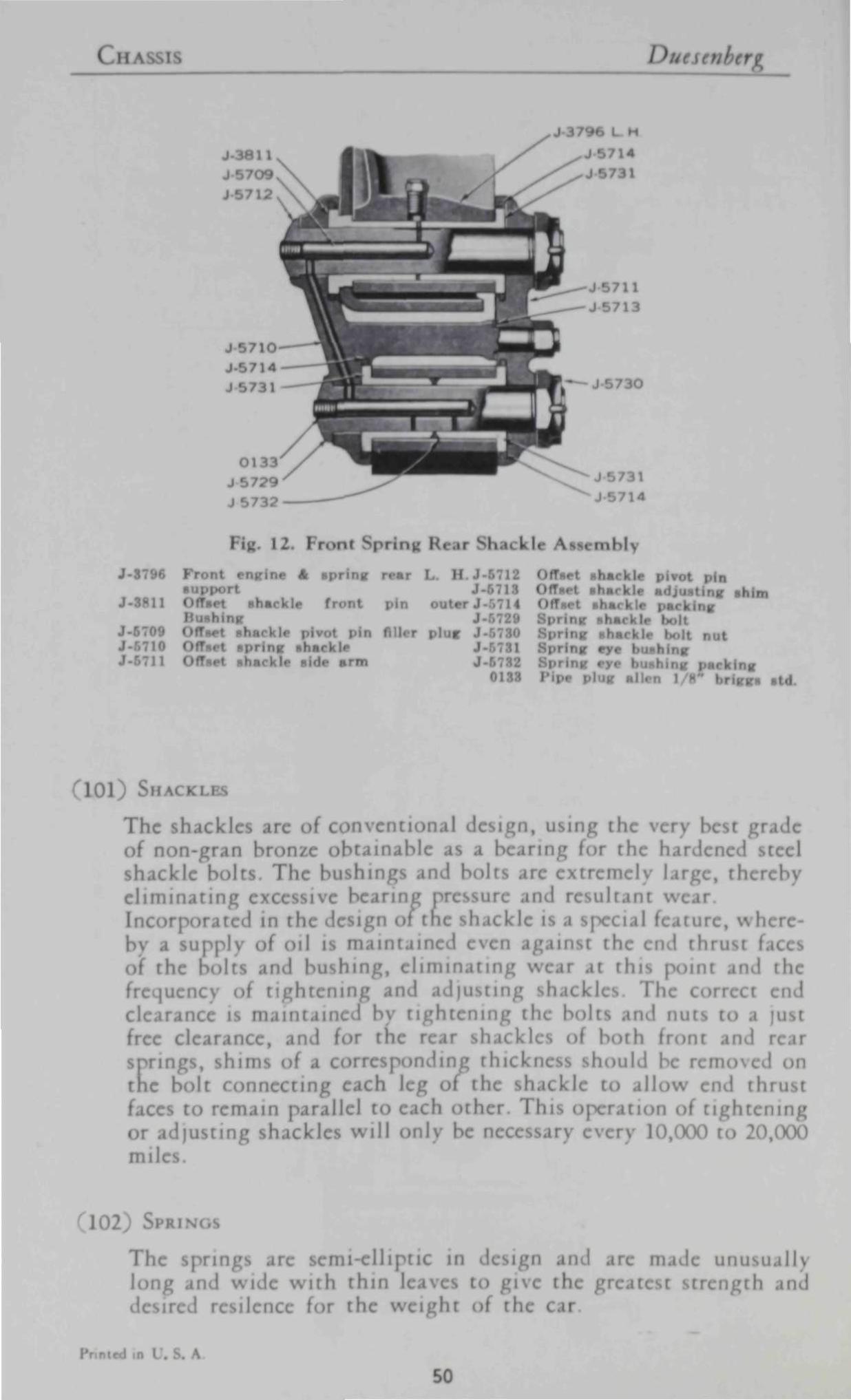
C H A N / h/esenberg
Fiu 12. Front Spring Rear Shackle AssemM>
J-3796 Front eng ine 4 spr ing rear L. H . J - 5 7 1 2 support J-
J-3H11 of fset shackle front m outer J-.',714 ishh J-r.729
J-5709 Offset shacl lug J-710 Offset spr ing shackle J
J-5711 Offset shackle side arm J-5732 0133
ifset shackle pivot pin Offset shackle adjust ing shim
Tset shar I i |m< king ig shackle bolt
;'Hng shackle lx.lt nut eye I h m g
g pack ing plug alien 1 . r , Bt
101) SHACKLES
The shackles are of conventional design, u g the very I | grade of non-gran bronze obtainable 'fing for the hardened teel shackle bolts The bushin ind bol ire extremely large, therel e l iminat ing cxi ivc bearing pressure and result vv< Incorporated in the design of the shackle pecial I ure, \% hereby a supply i >il is maintained e n against the cnA thrust of the bolts ' shing, elimii ng v\ this poini and the frequenc >f t ightening and adjusting shackles I he correct end clearance il maintained bv t ightening the bolt I nuts to a just free clearance, and for the rear shack I f both t it and rear springs, shims of a corresponding thickne hould be removed i tnc bolt connecting each leg ol the shackle to al low i th faces to remain j illcl to each otlu I his oj itioil ol t ightening or adjusting si k i d will onlv be necessary every 10,(XX) to 20,(XX) mile
102 SPRIN
The springs arc semi-elliptic in design and are made unusuallv long and wide wi th thin leaves to give the greatest strength ai desire ' r< lilence for the weight of the car
. A
50

Duesenberg E L E C T R I C A L S Y S T E M
103) Si k ABSORBERS
The shock absorbers, control or check the spring action for extreme movement both in the upward and downward directions. Thus it will be found that under all road conditions exceptionally g> ; riding qualities will be maintained. The shock absorbers require no adjustment throughout the life time of the car It will of course be necessarv to maintain the proper supply of liquid in each unit, using only Delco-Remy shock absorber liquid obtainable at any of their branches.
ELECTRICAL SYSTEM
The ignition system is described under para iph 64-
104) GENERATOR
The generator is driven at crankshaft speed from accessory shaft on the left side of motor, thru short shaft using two flexible disc couplings. The armature rotates clockwise on two annular ball bearings which should receive 10 drops of light engine oil every 750 miles at the same time oil is changed in the motor. The generator is a two pole shunt unit using third brush regulation with cut out re mounted directly on housing.
105) CHARGING RATE
The charging rate is determined bv means of the position of the third brush To change the position of the brush loosen the round head locking screw located at one side of the bearing cover on the commutator end frame. Remove the cover band and shift the third brush in the direction of armature rotation to inert. the output and in the opposu I i recti on to decrease the output When the adjustment is completed tighten the round head screw securely 1 prevent brush changing position The charging rate should not I higher than 12 amperes when general or id lesser charging rates are recommended when lights and starting motor are noi used excessively The third brush control is supplemented 1 1 thermostat which is an automatic switch operated bv the heat inside the generator. When the batter . fully charged or the internal temperature of the generator reaches 165 degrees F. the contact open an resistance is placed in sei th the g< Id with the result that the genei n output ii reduced im \ 40 per cent This tvpe of control permit higher ch. ing rat> on short drives longer period in the winter time which helps to restore the battel \ charge. The brushes should be examined OCC; mall) to »ec that the re not worn excessively and if nect try clean armature with No. I sandpaper.
I', ntad in 1 \
SI

I ICA] / > •
a c u 0 at C
'C
si
a UJ
•d in i A. 52

Duesenberg E L E C T R I C A L S Y S T E M
CuT-Oin Ri LAY
The cut-out relax mounted on the genet frame serves to automatically connect the generator to the battery circuit when the voltage of th enera is equal to the voltage of the battery and to di nnect the circuit when the generator stops or the voltage-drops.
107 S MING MOTOR
The star t ing motor is a six volt, six brush, six pole series wound unit equipped with a bendix drive to ei ge ring gear on flywheel The bendix drive automatical ly eng S when rter control is pulled out at dash The armature is earned in graphi te bronze bushin which do not require lubrication Do not lubricate spiral shaft of bendix drive as it is only necessarv that it be thoroughly clean. The cover band should be removed occasionally to inspect brushes to see tha t the\ are not worn and commuta tor cleaned with No. 00 sandpaper.
108) CIRCUIT BREAKER
The circuit breaker mounted in front of dash on left hand side i protective device to disconnect circuit where there is an abnormal discharge or a short circuit This unit serves the pur| oi fuses and gives a bu/./ing signal to warn operator of the condition of svstem
•
109) L IOH 11 Swi rcH
The l ighting switch is located at the bottom of the steering column AnA is controlled In the third lever at the steering quadrant. No attention should be n e a iar) other than to keep the connections t ight .
] 10 ) A M MI II i<
The ammeter on the instrument panel indicates charging AnA A\ charging rates of the batter) or the correct operating condit of the entire n.
M l ; H O R N
The horn x volt motor driven type AnA should reC< W drop ;ht engine oil periodically.
1 l 2) Son.' \. ,i B.\ | i i RY
T h e ' >lt I re hout St carried in the compartment of the splash shield on the right ' the frame I he n< terminal is groun i the entire s\stem IS 0 Wll grounded, type The batter) terminals uld be cleaned penodicalK
Pi \ .
53

B O D Y Duesenberg
and given a thin coat of vaseline Water should be added to the battery to keep liquid Vi" above top of plates. The right hand upper signal light on the instrument board reminds you to inspect battery liquid every 1,500 miles.
(113) LIGHTS
Standard light equipment is: Headlight—High Beam 32CP, 6-8 Volts, S. C. base Headlight—Low Beam 21CP, 6-8 Volts, S. C. base Cowl Lights 3CP, 6-8 Volts, S. C. base Instrument Light 3CP, 6-8 Volts, S. C. base Tail Light 3CP, 6-8 Volts, S. C. base Backing and Stop Light 21CP, 6-8 Volts, S. C. base All connections should be inspected periodically to prevent open circuits and burning out bulbs.
BODY
(114) BODY
Since practically all bodies supplied on the present chassis are custom built, it is impossible to include maintenance instructions and replacement details for all makes and types. However information may be obtained upon application from this factory or the respective body builders supplv ing the equipment. In all correspondence be sure to state, body manufacturer, body style and type seating capacity serial numbers and as many details as arc available. In all cases give car number with above information.
I II I 1)1 I s )• \ | | I U (; I' It \ I I
Printed in U. S. A.
54

Duesenberg INDEX
hide x
A
Accelerator
Air Pressure Tires Alcohol Solution
Alignment Front W'hcc
Ammeter
Automatic Spark Advance
Ic Front
Ic Rear
PAKAORAPI
4
30
73 89
20
65 87
83
1 > i s t n b u t o r
1 N tin Cock Radutor Drag Link
E
Electrical System
1 -ngin
PAH U.RAPH
64-69
73
88
64-104 34
B
Batters t Fan Adjustment
I) Brakes Adjustment Brakes Principle
jkes—Rclining Brakes Hand Breaker Points
112
75
114
94
91
95
81
66
Fan Fan Belt Adjustment i w heel
Fool Brakes
oi Brake I I jus tment Fran i
i rcczii I recaucioni 1 Uignment
icl S\ si
75 75 46
91
99 73 89 59
Camshaft
Carburetor Adjustment Carburet' Msh Com
lains Timing ing I I >il
Charging Rate
i . ub r i La t '
I Springs ill Brcal
Clock Clutch
ntch Ad just men i P Ial Ignition
tndenscr
ing Rod
ting Rod Bearings
I - ding $\ stern
' la) I r lei Block
1)
Dash i ill Carburei I )asi I ! Start.
—i\ n I S. A.
54
59
5
55 38
105
100
102
10H
15 76 76
7 72
70 42
42
I
44
5
< rasoline (>augc ( LI .i ilii Pump
Ga ' »il 1 i ccdomi ( rears Shifting
. r a t i i
crator I ring R J
ling Valv<
H
Hand drake
Hand Brake Adjustment Hand rrul
Hand ["hrottl O introl i Intake
I h Mnl I ' H L
I I
I I,
I
lition < oil
Ignition I tistributoi
Ignition Sv h
63 61
17-37
.
9
104
105 57
81 81
2
60
23 I I I
^4
• 72
I
55

I N D E X Duesenberg
Ignit ion Timing Inspection Schedule Instrument Lights Intake Heater
PARAGRAPH
67 33 22 60
PARAORA
Lamps Lighting Switch Light Mulbs Lubrication- Motor Lubrication Specifications Lubricator—Chassis
109 113
34 39
100
M
Main Bcarin* 41 Motor 40 Motor Oil Motor—Starting 107
O
Oil Change 3H i Gauge 61-62
Oil Pan. 45 Oil Pressure Adjustment 36
I Pump 35
oi l Rectifier I Specificai 39
Operation 30
Shifting Gears Shock Absorbers Spark Hand Control Spark Plugs Spark Timing
Speedometer Speedometer Gears
Springs Starter Control Starting the Engine. Starting Motor
Steering Gear Steering Reach Rod Storage Batterv S\\ itch -Ignition S\\ itch Lighting
Tappets Throttle Timing Contaci Timing Chains Timing Ignition Timing Valves I ire Pressure
Torque Tube Transmis
9 103
3 71 67
14 80
102 6 6
107
98 88
112
1
109
50 22 66 55 67 56 30 86
79
U
HI
Pi icon Pin HI Rim
Plugs Spark c p a n n g Car for Scr\ i
Propeller Shaft imp OH
Pump Water
Radiatoi Radia tn p Radia tor H>> I onnc< iio Reach Rod Drag Link
Re t iming Bi
4}
4}
4}
71 30 86
35 75
73 24 74 88
95
Universal Jo in !
V
Valves \ alve Adjustment Valve Gr inding Valve Guides Valve Springs Valve Tappets \ ' a l \ c T iming
W
Water Pump Wheels Aligning Mil Who.
82
49
51 57 52
53 50 56
75 I
htCvl 111 \ \ A .
56

1/1
r //
rA #. / I T
(ft) I hi i
tiU floors
T H K. 1) l | o i u § I

I'nusual body width has been th*
I this design. Sist persons ride
co rtat>ly in (he rear compart-
mtnt The large upholstered aus*
iary chmrr fold completely out of
tight The rear seat is adjustable.
co
T H E D U E S ! S I M R G L I M O U S I N E

/ his model is design* 'dally
for those desiring mmsrimmm com-rt and en <>nal headroom It
has high windows afv g excel
lent vision hmrgi high doors per
mit comfortable intra >dy lines
are of the square, formal type.
S
T HK i B S 1 \ iw K G 1 u \s \ L I If O I S I N K

MKsJ ft'tturts of this tn ITS
long, low. rakish lines; exceptional
tC thin, ditrnlw in
rner posts modi ttic hitc
harv hardware and \igh'
ebony I rear-fn
orr tl chairs.
o
T H E I) I E S I N B E R G f O W N I \ K

BOOKS on HISTORICAL AUTOMOBJLES k ?4MOMS MOT**? scMPeo<?*r$ i
MOTOR HISTORY OF AMERICA PROFUSELY ILLUSTRATED . . . 4 1 6 PAGES
Wr i t ten by C. B Glasscock, with histor ical Scropboob supple
ment by Floyd Clymer A complete account of the g rowth of the
automobi le industry from its beg inn ing . Detai led activi t ies of men
who have made automot ive history — Ford, Buick, Chrysler, W i l l y s ,
Dodge, Ket ter ing, Hoynes, W m t o n , Chalmers, M a x w e l l , Fisher,
Duryeo, O lds , Duront , Joy, Nash , Cord and other pioneers.
LISTS THE NAMES OF OVER 1,600 U S MAKES OF PASSENGER
CARS — gas, electric and steomers A mine of automot ive infor
mat ion — concise, complete and ou thon ta ' i ve .
Postpaid $3.00' » i o * 0 C l T j I t '
Floyd Clymer's Historical MOTOR SCRAPBOOK No. 6
224 poges Here it the latest and most interesting In the Motor Scrap-boob Series Doxeni of eorly mokes of American cars ore shown that hove never before been -lluttroted in boobs Besides old favorites, see and reod about tl.e Copeland, ftiber. Brower, Storm, Buffalo. Sandusky, Worw»cb, Brecht. Mohawk, Union, Reber, Dyke, long Distance, Bucbmo-bile, Sommer. Dawson. Eldredge, Covert, Colt, Monarch, Decouville, Ferris, Premocor. Corrm. Noma. Cearless, Bay Stote, Airmobile, and others Alio many mokes of old motorcycle* Every antique enthusiast - i l l wont this lotest and MOST UNIQUE Clymer +*) (\(\ Scrapboob, No 6 Postpaid T ^ - ^ ^ De lu»e Edition, Fobnboid bound with Gold lea' lettering $3.00
MOTOR SCRAPBOOK N o . 5 This f i f th book m the Clymer Scrapbook Series shows ads and
pictures of automobi les ond motorcycles from 1895 lo 1933
Some of the greatest names in American Automob i le History
are presented in this ar ray of manufacturers Mr Clymer tel ls
of his ear ly racing career os wel l as a l l i n fo rmat ion about the
once popular Clymer Windsh ie ld Spot l ight This ed i t ion is dif
ferent from previous Scropbooks . . . There is no dup l ica t ion in
any of these books
Postpaid, $2.00 De Luxe Edition, $3.00
The Famous MOTOR SCRAPBOOK SERIES
Floyd Clymer t Hutoricol Motor Scropbooks show
by meons of reproductions of origmol odverdse
menfi ond photos, hundreds of eorly American
automobiles ond motorcycles Cori ihown include
Brush, E M F. Maynei, Hup, Met*. Orient. Pope.
Rambler, Diana, Gordner, Mormon. 2 cyl Ford,
Kisselbor. Jeffe'y, Soion, Wmton, loner, loco
mobile. Stuti and otheri, also many steom cori,
electrics and motorcycles Edit.oni 1, 2. 3 ond 4,
eoch entirely different m content ftegulor Edition,
each, $1 SO, De lu i« Cloth Bound, eoch. $2 50
All boobi prepoid
1,250,000 CLYMER MOTORBOOK READERS THROUGHOUT THE WORLD!
Clymer Motorbooks are a must for those interested m ant ique and modern cars ond motor racing Thousands now have l ib rar ies con taming these new and interesting volumes heretofore unobta inable
F L O Y D C L Y M E R , Publisher 1268 SOUTH ALVARADO STREET, LOS ANGELES 6, CALIFORNIA

I I
Book of the
MEXICAN ROAD RACE Carrera Panamericana"
A new book abou t o n exc i t i ng race the
2178 mi le r o o d race across Mex ico f rom El Poso, Texas, to the G u a t e m a l a n Border Leg by leg h is tory comple te w i t h stat ist ics, rules a n d r e g u l a t i o n s , art ic les by the w in ner, Herschel McGnfF, ond other no ted au thor i t i es 3 5 0 ac t ion pho tos o n d
i l l us t ra t ions A la rge 152 page book w i th no d e t a i l om i t t ed includes o
t rave log o i Mex i co ' s new super - h igh w a y
plus scenic photos of h is tor ica l a n d co lo r fu l
O l d M e x i c o Postpa id $ 2 . 0 0
Deluxe Ed i t ion w i th F o b n k o i d b i n d i n g o n d
G o l d leaf l e t te r i ng S 3 . 5 0
SPECIAL R A C I N G CARS
A N D HOT RODS
SOUPING THE STOCK ENGINE
fully the 5 PATHS TO POWER. 1 10 i nck en
gine! effective theoi >n speed l imine HOW arid WHY huu I >ur jping"
ar nplete on speed lurnrif of ALL MAKES of STOCK ENGINES. Best
speed ever writ ten! 150 photos, IrmwinfS Bferj i ,p*d enthiuust
; uaiii i h i l ALL-NEW, mmpleie tiuu I t>y Honer Hunting pages
$ 2 . 0 0
SERVICE MANUALS
Over 160 Fotos, Charts Drawings on Special Race Cars England, Germany, France, Austral.a. U. S , Italy. A complete Manual of Speed data. Handbook lor construction $ 1 . 5 0
SPORTS CAR ENGINE
A new book . . . 40 Fotos, charts, drawings Technical and all other data on all Sports Car Engines A MUST for Sports Car Fans $ 1 . 5 0
FLOYD CLYMER. Publisher 1268 So. A l v o r o d o , L o * A n g e l e s 6. C a l i f
CHEVROLET OWNER'S H A N D B O O K
Complete new service data book, all Chevrolet* 1929 to 1950 including Powerglide model. Every Chev owner needs this manual. Many charts, drawings, sketches on every important unit Postpaid $ 1 . 5 0
FORD O W N E R S H A N D B O O K
Complete maintenance and repair data Covers ALL models 1932 to 1950. Charts, drawings, pictures. and tables of clearances and adjustments Data on Ford SIX included. The only COMPLETE Ford re pair book on the market Covers all parts of the car, engine, transmission, rear end, electrical system, fuel system, brakes, shock ab sorbers, steering and every other important part Postpaid $ 1 . 5 0

1 9 5 1 Ind ianapo l i s Race Of f i c ia l Y e a r b o o k ( W i t h e n l o r g e d , a u t h e n t i c t e c h n i c a l s e c t i o n i n c l u d e d ) The complete story of the great 500-mile race held on Memorial Day, 1951 . . . 112 pages filled with interesting ond informative text, over 300 photos — of drivers, their cars, important personalities . . . special new section devoted eaclusively to technical aspects of the race . . facts concerning front and rear-drive cars, the successful Meyer-Drake (Oflenhouser) racing engine, the story of the fabulous Novi Specials. The many excellent photos, dcawi«g$, cartoons, provide on accurate account of the qualifying tr ials, the ro<e itse*f, post-race activities, and winner Lee Wallard's victory celebration. Postpaid - , $1 50 Deluxe Edition, Fobnkoid bound. Gold Leaf lettering $3.00
JUST PUBLISHED NEW YORK TO PARIS RACE, 1908
7 6 Pages . . . 109 p h o t o s . This b o o k
te l ls of W o r l d ' s Longes t Race , w o n b y
a Thomas -F l ye r . Photos of ca rs in a l l
c o u n t r i e s . S ta r t a t T imes B l d g . , N .Y .C . ,
snows in M i d - W e s t , s a g e b r u s h a n d s a n d
in W y o m i n g , A l a s k a , J a p a n , Russian
so l d i e r s , T r a n s - S i b e r i a n R a i l w a y s , M o n
g o l i a n g i a n t s , t h e r e t u r n t o Times
S q u a r e A c o l o r f u l s tory a b o u t a n un
b e l i e v a b l e a r o u n d - t h e - w o r l d r a c e in
1 9 0 8 . The Thomas -F l ye r w a s t h e n ac
c l a i m e d t h e ' W o r l d ' s C h a m p i o n En
d u r a n c e C a r ' A r e a l b o o k of A m e r i
c a n a . P o s t p a i d $ 1.00
CORD OWNER'S M A N U A L REPRINT This 36 page book gives o i l d r i v i n g instruct ions o n d necessary servic ing in for mat ion for Cord V-8 cars. Comple te specif ica t ions, 20 pho tos , char ts , d r a w i n g s . A l l abou t care of e n g i n e , t rans . , f ront d r i ve , c lu tch, e lectr ica l e q u i p m e n t , t i m i n g , coo l ing system, fue l system l u b r i c o t i o n , f ron t s teer ing d a t a , un ive rsa l * , a l i g n m e n t , hyd raul ic b rakes , shocks, top a n d t i res. A
must* for every Cord owne r or enthusiast in terested in des ign of this un ique f r o n t - w h e e l - d r i v e n car. O r d e r repr in t No 2 - C 0 8 1 0 Postpa.d $1 0 0
STUTZ CATALOG REPRINT 25 pho tos , speci f icat ions a l l famous 4 -cy l inder Stutz series E' cars i nc lud ing the f abu lous B e a r c a t " , Roadster a n d Tour ing mode ls , in bo th 4 a n d 6-cy l inder -powered cars. Order N 6 . E-STU. Po p a i d 51 0 0
MERCER CATALOG REPRINTS Comple te d a t a on this W o r l d - f a m o u s car of ea r l y days . Photos a n d speci f icat ions of a l l models and b o d y styles, i nc lud ing the o u s t a n d i n g RACEABOUTS. Series " 5 " 4 cy l inder mode ls . O r d e r Reprint No . 5 Mer Postpa id $1 0 0 Series " 6 " 6 -cy lmder O H V models. Order Repr.nt No . 6 -Mer . Postpa id $ 1 . 0 0
M A R M O N MODEL 34 CATALOG REPRINT Probob ly the f inest a n d most i n fo rma t i ve ca ta log of ea r l y d a y cars. 46 la rge p a g e s , complete a n d b e a u t i f u l pho tos , un ique b o d y sty les, e n g i n e , chassis, every fea ture m inu te ly descr ibed a n d i l l u s t r a ted , cu taway views of eng ine a n d o ther units A col lectors i tem w i t hou t compar i son . Or der Repr.nt No . 3 4 - M a r . Pos tpa id $ 1 . 0 0
REO INSTRUCTION BOOK REPRINT Covers a l l 2 - cy lmder models ( 1 9 0 5 to 1 9 1 1 ) a lso app l i es to one -cy l i nde r Reo cars. Comp le te service d a t a . O r d e r Re pr in t No 0 9 - R e o . Postpa id $ 1 . 0 0
REO CATALOG REPRINT, 1908 Covers o n e - a n d t w o - c y l i n d e r Runabout , T o u r i n g , a n d Roadster models . Specif icat ions , f ea tu res , chassis, sales c la ims , t ransmiss ion , a n d brakes. 1 2 nice pho tos . O r d e r Reprint N o . 08 -Reo . Postpa id $ 1 . 0 0
MERCEDES-BENZ MODEL S CATALOG REPRINT
Photos of car, bo th sides of chassis, eng i n e , features a n d speci f icat ions. O r d e r Reprint No . 2 MBS. Postpa id $ 1 . 0 0
1916 HARLEY-DAVIDSON "En thus ias t REPRINT
In te res t ing 1 9 1 6 3 0 0 mi le Dodge City Motorcyc le C h a m p i o n s h i p Race a n d o ther f asc ina t i ng d a t a on motorcyc l ing events of 1 9 1 6 . Photos a n d d a t a on d u a l ( 8 ) va lve H-D racer. Order Reprint No . 16-HD. Postpa id 50c
An original NOT a reprint BUICK L i m i t e d " SOUVENIR CATALOG
Covers 8 d i f fe ren t 1 9 4 0 models. 37 beaut i f u l color i l l us t ra t ions of in te r io r a n d exter ior Both S tanda rd a n d Custom Series 80 a n d 9 0 . Mode l s 9 1 , 9 0 - L , 8 1 - C , 81 F, 8 7 , 87-F a n d 87 C. Data on Dynaf lcuh e n g i n e , fu l l chassis, e n g i n e a n d dash speci f icat ions, o n d color shots. 20 la rge pages ( 1 4 x 1 6 ) , sp i ra l b i n d i n g w i t h wh i te embossed art paper covers. O n e of the f inest a n d most co lo r fu l ca ta logs ever p r i n t e d . Truly a co l l ec to rs i tem a n d the last of the p lush ca ta logs . Postpa id .75
F L O Y D C L Y M E R , Publisher 1268 SOUTH ALVARADO STREET, LOS ANGELES 6, CALIFORNIA

JVOO
*?(<Hfc{ glymCU *£<ttC4t. ^(fUSCAt <Uut &C4* *&<H%4f
REASUR1 01 EARL1 AMERICAN AUTOMOBILES, L877-1925 by FLOYD ( I YMI H I d by Jamt •• Melton
ll') pa, 500 [Uuttrai tt
A Hi
"i i > i
i red
ilc
THEASUR1 EARLY AMI Kh AI »BI1 i
M. Hut ' ' autrv I
H he Ii f H e n r y 1 l<
I . 87 Model I ( i i tli'
thi album wil l id ' I -
/ • -. n< ill
F L O ^ with tl •Idfu
| , the I wheel ) I H
th ' I i
>r them K im
t id )
rd ' In r<
• bo th-
Published by McGRAW-HILL BOOK CO. , N e w York City
Order f rom FLOYD CLYMER, 1268 S. A lvorodo, Los Angeles 6
Clymer Reprint No. 4-JDR


![6LHPHQV ±SR]LRP F] ühome.agh.edu.pl/flaga_st/m/Kurs-czesc-01.pdf · 2017-04-23 · 0.625 Hzclock: 0.5 clock: e ofclock memory byte 00.0 (clock 10Hz) (clock 5Hz) (clock 2. (cl (clock](https://img.pdfslide.net/doc/110x75/5e792c30ca7263576743b389/6lhphqv-srlrp-f-homeagheduplflagastmkurs-czesc-01pdf-2017-04-23.jpg)