Embed Size (px)
Citation preview
i
i-
. ‘. .
STAR XL4600 XL4605 Hookup and Installation Instructions . ._*
A Division of Pittway Cotporation
163 Eileen Way, Syosset, NY i1751 c (800) 654-5430 l (516) 921-8666
0. U L @
REV. B Fl2384 8189
STAR XL4600 XL4605 -
TABLE OF CONTENTS , 2
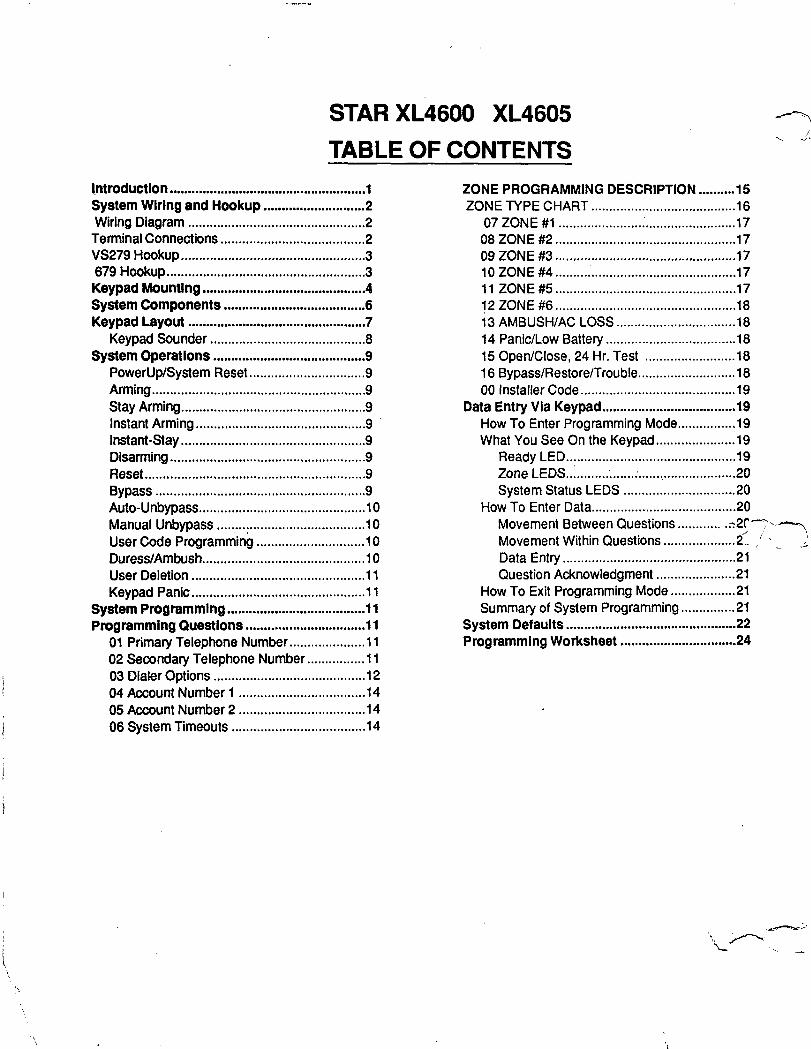
l,ntroductlon ...................................................... 1 System Wiring and Hookup ............................ 2 Wiring Diagram ................................................ .2 Terminal Connections ........................................ 2 VS279 Hookup.. ................................................ .3 679 Hookup ....................................................... 3 Keypad Mounting ............................................. 4 System Components ....................................... 6 Keypad Layout ................................................. 7
Keypad Sounder ........................................... . System Operations .......................................... 9
PowerUp/System Reset ................................ 9 Arming.. ........................................................ .9 Stay Arming.. ................................................ .9 Instant Arming ............................................... 9 Instant-Stay ................................................... 9 Disarming.. ................................................... .9 Reset.. .......................................................... .9 Bypass .......................................................... . Auto-Unbypass.. ........................................... .10 Manual Unbypass ......................................... 10 User Code Programn&~ .............................. 10 Duress/Ambush.. .......................................... .1 0 User Deletion ............................................... .l 1 Keypad Panic ................................................ 11
System ProgrammIng ...................................... 11 Programming Questlons ................................. 11
01 Primary Telephone Number.. .................. .l 1 02 Secondary Telephone Number.. ............. -11 03 Dialer Options .......................................... 12 04 Account Number 1 ................................... 14 05 Account Number 2 ................................... 14 06 System Timeouts ..................................... 14
ZONE PROGRAMMING DESCRIPTION.. ....... .15 ZONE TYPE CHART.. ..................................... .16
07 ZONE #l ............... ..*...... ......................... 17 08 ZONE #2.. ............................................... .17 09 ZONE ## .................................................. 17 10 ZONE #4 ................................................. .17 11 ZONE#5 ................................................. .17 12 ZONE #6.. ............................................... .18 13 AMBUSH/AC LOSS ................................ .18 14 Panic/Low Battery ................................... .18 15 Open/Close, 24 Hr. Test ........................ .18 16 Bypass/Restore/Trouble.. ........................ .18 00 Installer Code.. ........................................ .19
Data Entry Via Keypad ..................................... 19 How To Enter Programming Mode.. ............. .19 What You See On the Keypad.. ................... .19
Ready LED.. ............................................ .19 Zone LEDS ..:. ........ . ...... . .... ..?. .................. .20 System Status LEDS .............................. .20
How To Enter Data.. ..................................... .20 Movement Between Questions .-2CT- Movement Within Questions ............................. . .. .2! ,’ _ 1 Data Entry ................................................ 21 Question Acknowledgment ..................... .21
How To Exit Programming Mode.. ............... .21 Summary of System Programming.. ............ .21
System Defaults ............................................... 22 Programming Worksheet ................................ 24
1 m INTRODUCTION
The STAR XL-4600 is a state of the art EEPROM based control/communicator. The system features six fully programmable zones as well as a wired panic zone. Programming can be performed through the keypad or the system can be uploaded and downloaded locally using the EZ-Mate Programmer. The STAR XL-4600 contains up to six user codes with an ambush code capability. All of the keypads are four wire devices, with up to four keypads per system. The XL4605 is the commercial UL version of the XL4600.
2 m SYSTEM WIRING AND HOOKUP
2.1. SYSTEM WIRING DIAGRAM
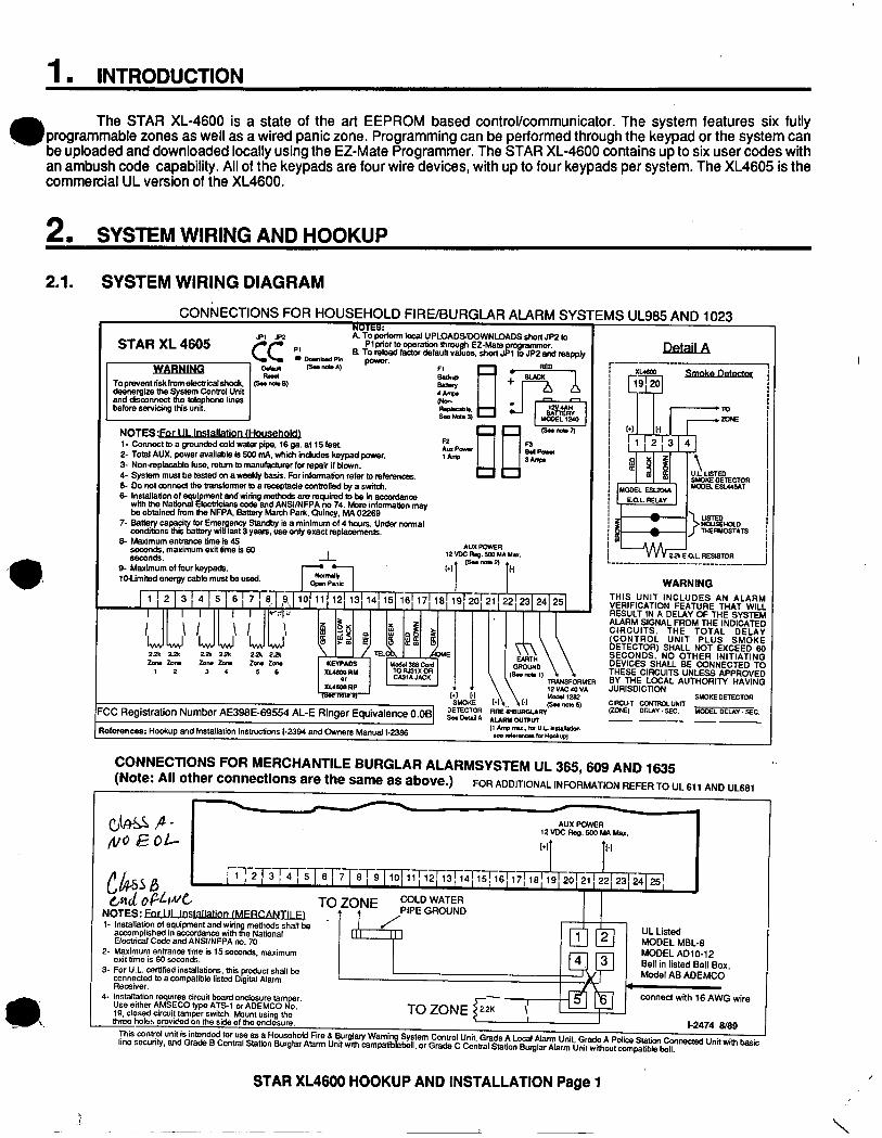
F CONNECTIONS FOR HOUSEHOLD FIRE/BURGLAR ALARM SYSTEMS UL985 AND 1023 f
STAR XL 4605 JPl m
cc PI
WARNlNG t!!!! -
. . - . --. A. To pmfonn local UPLOADS/DOWNLOADS short JP2 to
Pl prior to operation m h EZ-Male 9. To doad fador default v -~ pir T c
togrammer. ues, shori J 1 to JP2 and reapply
(srmc*l pauer.
NOTES- -- l- Connect to a grounded e~!d water piw. 16 ga. at 15 feat. 2- Total AUX. po%er available is 500 ;ni\. which indudes keypad power. ;“;-I I I I??? e. 3- Non-mplacable fuse. rehlm b, manufacturer for repair if blown. 4- System must be tested on a weekly basis. For infcfmalion refer to mfemncas. tkr S- Do ml conned the banslonner to a recsotade conbolled bv a switch. 6-~~~~o~na~~~me”landwimgmet~anrrequiredtDbeinaccordana,
lecbidans code and ANSIINFPA no 74. More information may be obtained from tie NFPA. Saaery March Park. Cvincy, MA 02269
7- Satbxry capad codoons thts ‘6,
for Emergency Standby Is a minimum of 4 hous. Under normal ttel-4 will last 3 Yeam. use onlv exact mDlarnmank
9. Maximum of four keypads.
gq
1.1t pjrea Il.1 lOLImIted energy cable must be used. a
FC
Ae1 femnces: Hookup and Installation In~buclions l-2394 and Owners Manual l-2386
Detail XLAEXO
CD- 19 20
;a
>
L!sTEn HOlJSElUXO
6 THERUOSTATS
22% E.0.L RESWOR .--------__- ____
I AUX POWER 12VDcReg.5mM4Max.
“‘I T”
T;T2 3p-j-i 6FT 9 101
COLD WATER NOTES: For 111 lostallation.LMERCANTlLEI PIPE GROUND
/
CONNECTIONS FOR MERCHANTILE BURGLAR ALARMSYSTEM UL 365,609 AND 1635 (Note: All other connections are the same as above.) FOR ADDITIONAL INFORMATION REFER TO UL 611 AND UL661
-
I- tnsmrm~n of ylpment and “itit methpds shall be accompkshed I” accordance wth e National
4- Installation requires circuit board enclosure tam Use either AMSECO type ATS-1 or ADEMCO
r$
r. o.
19. closed circuit tamper switch. Mount using the lhree holes orovided on the side of tie e~losum.
This ~n%l unit iS htmbd for “93 a.5 B Howehold Fire 8 @rglary Wamin line secunly. and G&s B Cental SWIO~ Burglar Alam UIM ~nth camp& .&,
System Control Unit. Grade A Lo& Alarm Unit Grade A Polk St&,, hnec(ed Unit witl, basic bell. or Grada C Central Station Surgbr Alarm tinit witbout compatible bell.
STAR XL4600 HOOKUP AND INSTALLATION Page 1
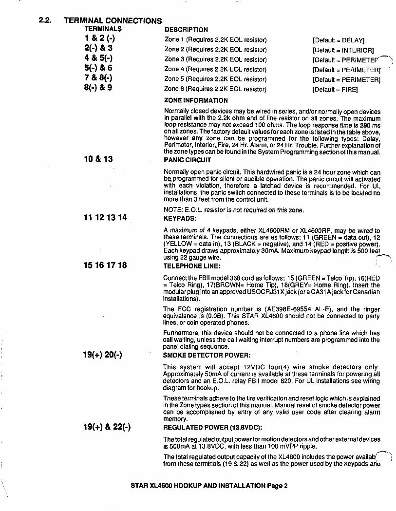
2.2. TERMINAL CONNECTIONS TERMINALS 1 & 2 (-) 2(-) & 3 4 & 5(-) 5(-) & 6 7 & 8(-) 8(-) & 9
10 & 13
11 121314
15 161718
19(+)20(g)
19(+)& 22(-)
DESCRIPTION Zone 1 (Requires 2.2K EOL resistor) Zone 2 (Requires 2.2K EOL resistor) Zone 3 (Requires 2.2K EOL resistor) Zone 4 (Requires 2.2K EOL resistor) Zone 5 (Requires 2.2K EOL resistor) Zone 6 (Requires 2.2K EOL resistor)
ZONE INFORMATION
[Default = DELAY] [Default = INTERIOR] [Default = PERIMETEP-\ [Default = PERIMETER].- ’ [Default = PERIMETER] [Default = FIRE]
Normally closed devices may be wired in series, and/or normally open devices in parallel with the 2.2k ohm end of line resistor on all zones. The maximum loop resistance may not exceed 100 ohms. The loop response time is 280 ms on all zones. The factory default values for each zone is listed in the table above, however any zone can be programmed for the following types: Delay, Perimeter, Interior,. Fire, 24 Hr. Alarm, or 24 Hr. Trouble. Further explanation of the zone types can be found in the System Programming section of this manual, PANIC CIRCUIT
Normally open panic circuit. This hardwired panic is a 24 hour zone which can be programmed for silent or audible operation. The panic circuit will activated with each violation, therefore a latched device is recommended. For UL installations, the panic switch connected to these terminals is to be located no more than 3 feet from the control unit. NOTE: E.O.L. resistor is not required on this zone. KEY PADS:
A maximum of 4 keypads, either XL4600RM or XL4600RP, may be wired to these terminals. The connections are as follows; 11 (GREEN = data out), 12 (YELLOW = data in), 13 (BLACK = negative), and 14 (RED = positive power). Each keypad draws approximately 30mA. Maximum keypad length is 500 feet using 22 gauge wire. TELEPHONE LINE:
.,7-l
Connect the FBI1 model 368 cord as follows; 15 (GREEN = Telco Tip), lG(RED = Telco Ring), 17(BROWN= Home Tip), 18(GREY= Home Ring): Insert the modular plug into an approved USOCRJ31 X jack (or a CA31A jack for Canadian installations). The FCC registration number is (AE396E-69554 AL-E), and the ringer equivalence is (O.OB). This STAR XL4600 should not be connected to party lihes, or coin operated phones. Furthermore, this device should not be connected to a phone line which has call waiting, unless the call waiting interrupt numbers are programmed into the panel dialing sequence. SMOKE DETECTOR POWER:
This system will accept 12VDC four(4) wire smoke detectors only. Approximately 5OmA of current is available at these terminals for powering all detectors and an E.O.L. relay FBI1 model 620. For UL installations see wiring diagram for hookup. These terminals adhere to the fire verification and reset logic which is explained in the Zone types section of this manual. Manual reset of smoke detector power can be accomplished by entry of any valid user code after clearing alarm memory. REGULATED POWER (13.8VDC):
The total regulated output powerfor motion detectors and other external devices is 500mA at 13.8VDC with less than 100 mVPP ripple. The total regulated output capacity of the XL4600 includes the power availabf-j from these termlnals (19 & 22) as well as the power used by the keypads aho ’
STAR XL4600 HOOKUP AND INSTALLATION Page 2
smoke detectors. Therefore, to determine the total power available from these terminals subtract the>power consumed by the keypads and smoke detectors.
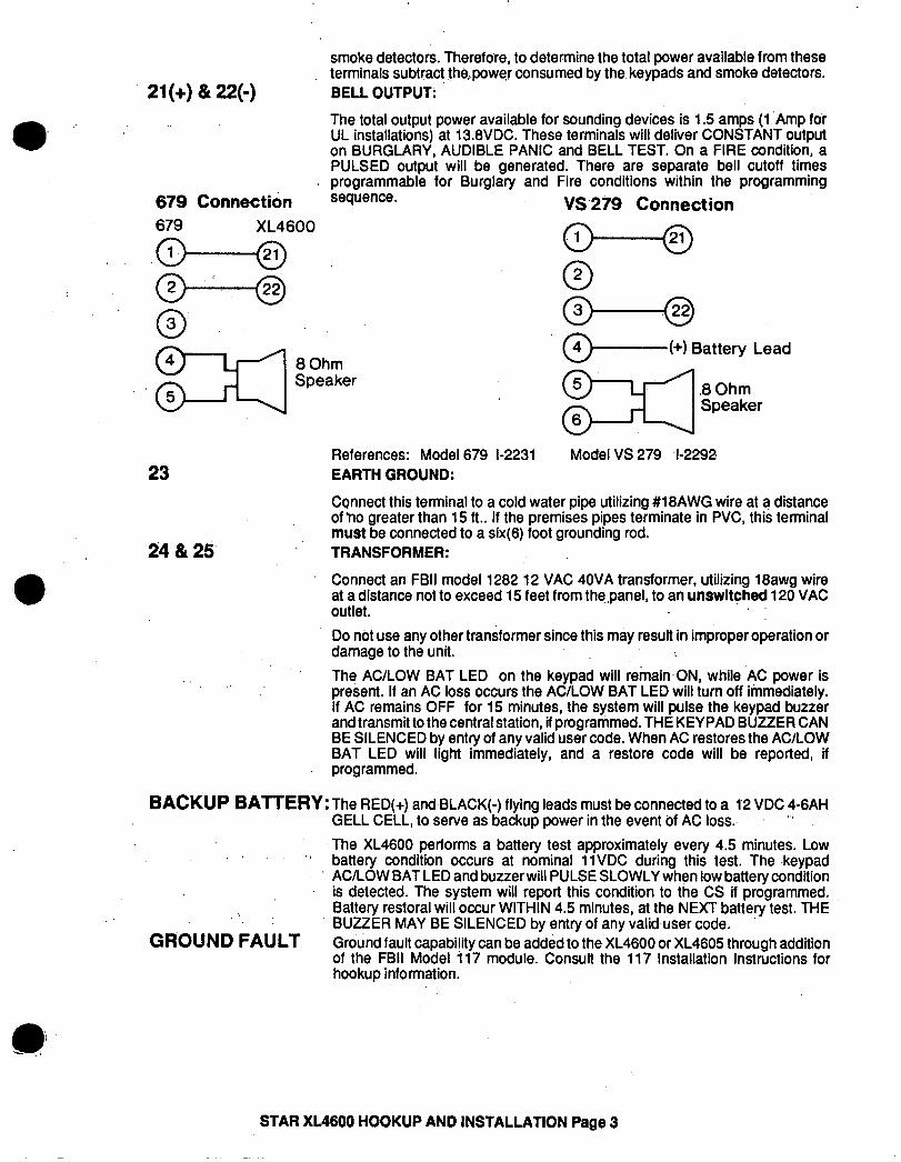
21(+) & 22(-) ’ BELL OUTPUT: ’
The,total output power available for sounding devices is 1.5 amps (1 ‘Amp for UL installations) at 13.8VDC. These terminals will deliver CONSTANT output on BURGLARY, AUDIBLE PANtC and BELL TEST. On a FIRE condition, a PULSED output will be generated. There are separate bell cutoff times programmable for Burglary and Fire conditions within the programming
679 Connecti& sequence. VS.279 Connection 679 XL4600
8 Ohm Speaker
0 6-B e (+) Battery Lead
.a Ohm Speaker
23 References: Model 679 l-2231 EARTH GROUND:
Model VS 279 l-2292
24 & 25’
Cqnnect this terminal to a cold water pipe utilizing #18AWG wire at a distance of ‘no greater than 15 ft.. If the premises pipes terminate in PVC, this terminal must be connected to a six(6) foot grounding rod. TRANSFORMER:
. Connect an FBI1 model 1282 12 VAC 40VA transformer, utilizing 18awg wire at a distance not to exceed 15 feet from the,panel, to an unswltched 120 VAC outlet. Do not use any other transformer since this may result in improper operation or damage to the unit. The AC/LOW BAT LED on the keypad will remain.ON, wtiile AC power is present. If an AC loss occurs the AC/LOW BAT LED will turn off immediately. If AC remains OFF for 15 minutes, the system will pulse the keypad buzzer and transmit to the central station, if programmed. THE KEY PAD BUZZER CAN BE SILENCED by entry of any valid user code. When AC restores the ACROW BAT LED will light immediately, and a restore code will be reported, if programmed.
BACKUP BAlTERY: The RED(+) and,BLACK(-) flying leads must be connected to a 1’2 VDC 4-6AH GELL CELL, to serve as backup power in the event bf AC loss. “’
The XL4600 performs a battery test approximately every 4.5 minutes. Low ,I
:
battery condition occurs at nominal 11VDC during this test. The -keypad AC/LOW BAT LED and buzzer will PULSE SLOWLY when low battery condition is detected. The system will report this condition to the CS if programmed. Battery restoral will occur WITHIN 4.5 minutes, at the NEXT battery test. THE BUZZER MAY BE SILENCED by entry of any valid,user code.
.GROUND FAULT Ground fault capability can be added to the XL4600 or XL4605 through addition of the FBI1 Model i 17 module. Consult the 117 Installation Instructions for hookup information.
STAR XL4600 HOOKUP AND INSTALLATION Page 3
3 m KEYPAD MOUNTING 7-J
3.1. XL46OORM METAL KEYPAD \
FLUSH MOUNTING WITH MOUNTING RING (Using the
‘. .
optional
‘ _’ ‘I,.‘?, .
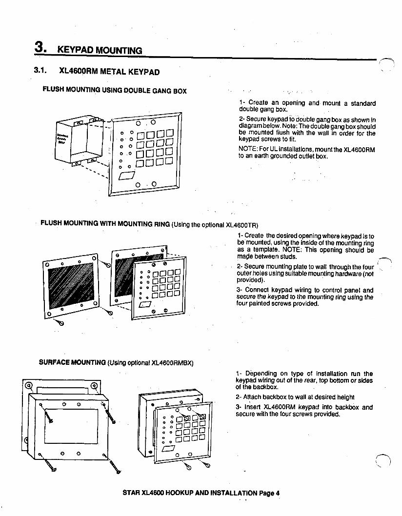
l- Create an opening and, mount a standard ,double gang box. 2- Secure keypad to double gang box as shown in diagram below. Note: The double gang box should be mounted flush with the wall in order for the keypad screws to fit. NOTE: For UL installations, mount the XL4600RM to an earth grounded outlet ,box.
XL4600TR) 1- Create the desired opening where keypad is to be’mounted, using the inside of the mounting ring as a template. NOTE: This opening should be made between studs. 2- Secure mounting plate to wall through the four ’ outer holes using suitable mounting hardware (not provided). 3- Connect keypad wiring to control panel and secure the keypad to the mounting ring using the four painted screws provided.
SURFACE MOUNTING (Using optional XL4600RMBX) l- Depending on type of installation run the keypad wiring out of the rear, top bottom or sides of the backbox. 2- Attach backbox to wall at desired height 3- Insert XL4600RM keypad into backbox and secure with the four screws provided.
. .w .
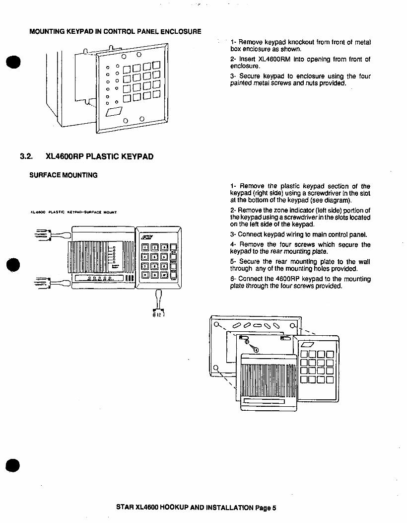
MOUNTING KEYPAD IN CONTROL PANEL ENCLOSURE
3.2. XL4600RP PLASTIC KEYPAD
SURFACE MOUNTING
- , R
l- Remove keypad knockout from front of metal box enclosure as shown. 2- Insert XL4600RM into opening from front of enclosure. 3- Secure keypad to enclosure using the four painted metal screws and nuts provided.
l- Remove the plastic keypad section of the keypad (right side) using a screwdriver in the slot at the bottom of the keypad (see diagram). 2- Remove the zone indicator (left side) portion of the keypad using a screwdriver in the slots located on the left side of the keypad. 3- Connect keypad wiring to main control panel. 4- Remove the four screws which secure the keypad to the rear mounting plate. 5- Secure the rear mounting plate to the wall through any of the mounting holes provided. 6- Connect the 4600RP keypad to the mounting plate through the four screws provided.
STAR XL4600 HOOKUP AND INSTALLATION Page 5
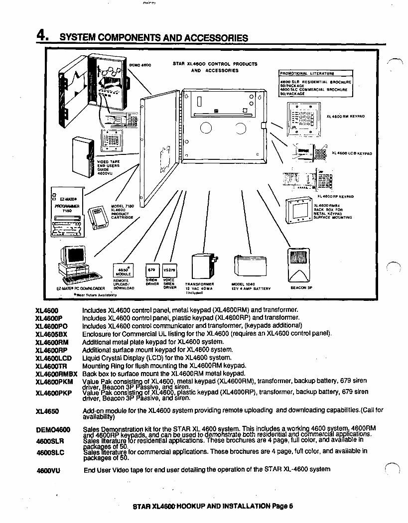
4. SYSTEM COMPONENTS AND ACCESSORIES
DEMO 4SOO
\
STAR XL4600 CONTROL PRODUCTS AND ACCESSORIES
X~460’0 RY KEI
Ez-NATE0 PC DCWNLOADER bOWNLOd
4600 SLR RESIDENTIA SO/PACKAGE 4600 SLC COMMERCIAL
XL4600 Includes XL4600 control panel, metal keypad (XL4600RM) and transformer. XL46ooP Includes XL4600 control panel, plastic keypad (XL4600RP) and transformer. XL466oPO Includes XL4600 control communicator and transformer, (keypads additional) XL4606BX Enclosure for Commercial UL listing for the XL4600 (requires an XL4600 control panel). XL46ooRM Additional metal plate keypad for XL4600 system. XL46omP Additional surface mount keypad for XL4600 system. XL46OOLCD Liquid Crystal Display (LCD) for the XL4606 system. XL46ooTR Mounting Ring for flush mounting the XL4600RM keypad. XL4600RMBX Back box to surface mount the XL4600RM metal keypad. XL46OOPKM Value Pak consistin of XL4600, metal keypad (XL4600RM), transformer, backup battery, 679 siren
driver, Beacon 3P Fp Value Pak consistin
assive, and siren. XL46OOPKP
driver, Beacon 3P # of XL4600, plastic keypad (XL4600RP), transformer, backup b,attery, 679 siren
assive, and siren.
I D
XLIBOORP KEIPAD
XL48GuRMBX SACK BOX FOR METAL KEVPAD
-...-._ .-.-- mI”ER SIREN TRANSFORMER MODEL 1240
DRIVER 12 VAC 40YA 12V 4 AMP BATTERY BEACON 3P
XL4650 Add-on module for the XL4600 system providing remote uploading and downloading capabilities.(Call for availability)
DEMO4606 Sales Demonstration kii for the STAR XL 4600 system. This includes a working 4600 systerni$46;\!M and 4600RP ke
r pads,.and can be used to demonstrate both residential and commercial a
Pp ’ 4600SLR Sales literature or resfdential applications. These brochures are 4 page, full color, and avai able in 4600sLc backayes of 50.
ales rterature for commercial applications. These brochures are 4 page, full color, and available in packages of 50.
46wvu End User Video tape for end user detailing the operation of the STAR XL-4600 system
STAR XL466BHOOKUP AND INSTALLATION Page 6
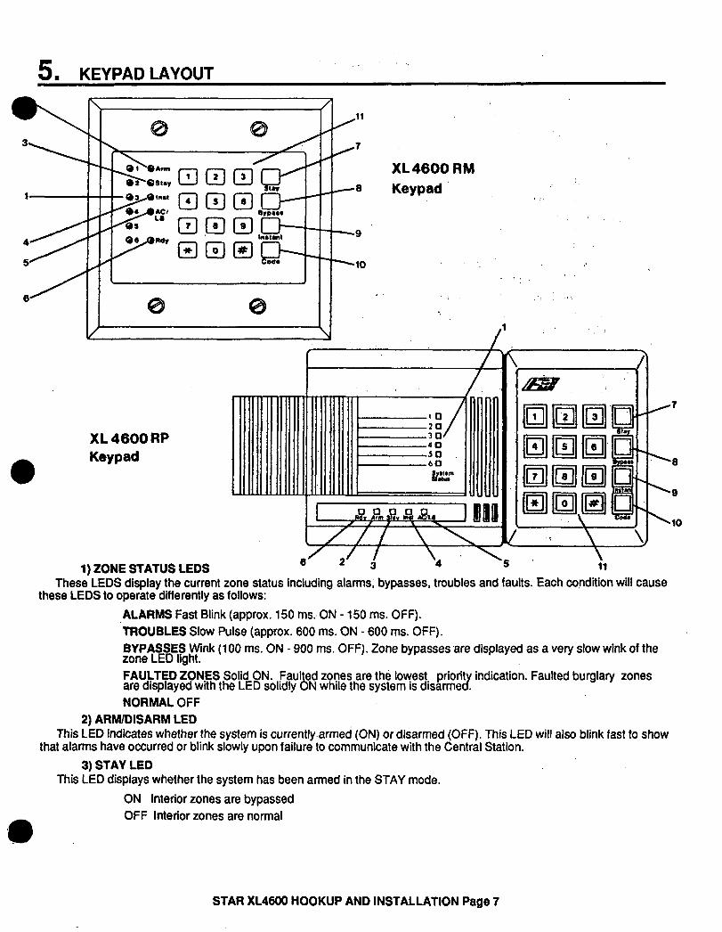
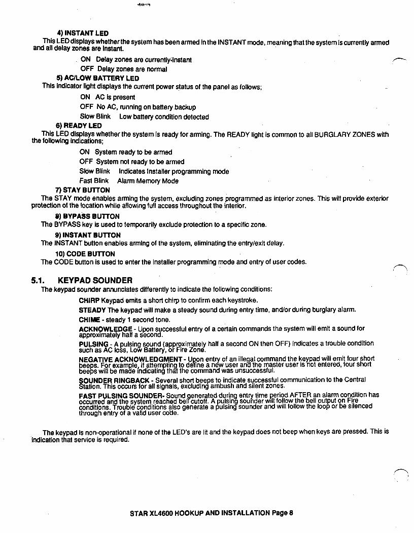
5 KEYPAD LAYOUT .
9
XL4600 RM Keypad
XL 4600 RP Keypad
1) ZONE STATUS LEDS i ii
These LEDS display the current zone status including alarms, bypasses, troubles and faults. Each condition will cause these LEDS to operate differently as follows:
'9
\lO
ALARMS Fast Blink (approx. 150 ms., ON - 150 ms. OFF). TROUBLES Slow Pulse (approx. 600 ms. ON - 600 ms. OFF). BYPASSES Wink (100 ms. ON - 900 ms. OFF). Zone bypasses ere displayed as a very slow wink of the zone LED light. FAULTED ZONES Solid ON. Faulted zones are the lowest priorit indication. Faulted burglary zones are displayed with the LED solidly ON while the system Is disarme cy . NORMAL OFF
2) ARM/DISARM LED This LED indicates whether the system is currently,armed (ON) or disarmed (OFF). This LED will also blink fast to show
that alarms have occurred or blink slowly upon failure to communicate with the Central Station. 3) STAY LED
This LED displays whether the system has been armed in the STAY mode.
ON Interior zones are bypassed OFF Interior zones are normal
STAR XL4600 HOOKUP AND INSTALLATION Page 7
4) INSTANT LED This LED displays whether the system has been armed in the INSTANT mode, meaning that the system is currently armed
and all delay zones are Instant.
ON Delay zones are currently;lnstant OFF Delay.zones are normal
5) AC/LOW BAITERY LED This indicator light displays the current power status of the panel as follows;
ON AC is present OFF No AC, running on battery backup Slow Blink Low battery condition detected
6) READY LED This LED displays whether the system is ready for arming. The READY light is common to all BURGLARY ZONES with
the following Indications;
ON System ready to be armed OFF System not ready to be armed Slow Blink Indicates Installer programming mode Fast Blink Alarm Memory Mode
7) STAY BUllON The STAY mode enables arming the system, excluding zones programmed as interior zones. This will provide exterior
protection of the location while allowing full access throughout the interior.
9) BYPA& BUTTON The BYPASS key is U88d to temporarily exclude protection to a specific zone.
9) INSTANT BUTTON The INSTANT button enables arming of the system, eliminating the entry/exit delay.
10) CODE BUTTON The CODE button is used to enter the installer programming mode and entry of user codes.
5.1. KEYPAD SOUNDER The keypad sounder annunciates differently to indicate the following conditions:
CHIRP Keypad emits a short chirp to confirm each keystroke. STEADY The keypad will make a steady sound during entry time, and/or during burglary alarm. CHIME - steady 1 second tone. ACKNOWLEDGE - Upon successful entry of a certain commands the system will emit a sound for approximately half a second. PULSING - A pulsing sound (approximately half a second ON then OFF) indicates a trouble condition such as AC loss, Low Battery, or Fire Zone. NEGATIVE beeps. For example, if
the keypad will emit four short IS not entered, four short
beeps will be made SOUNDER RINGBACK - Several short beeps to indicate successful communication to the Central Station. This occurs for all signals, excluding ambush and silent zones. FAST PULSING SOUNDER- Sound occurred and the system reached be If
enerated during entry time period AFTER an alarm condition has cutoff. A pulsing sounder WIII foflow the bell output on F!re
conditions. Trouble conditions also generate a pulsing sounder and WIII follow the loop or be silenced through entry of a valid user coUe.
The keypad is non-operational if none of the LED’s are lit and the keypad does not beep when keys are pressed. This is indication that service is required.
STAR XL4600 HOOKUP AND INSTALLATION Page 8
I.”
6 . SYSTEM OPERATIONS , jl
a 6.1. POWER UP/SYSTEM RESET Upon initial powerup of the XL4600 , all of the lights on the keypad will go on and the sounder will operate for
approximately 10 seconds. This occurs on a total powerup , system reset or after completion of system programming. If the total system power is lost then upon power restoral, the XL4600 will return to the previous arming state.
6.2. ARMING THE SYSTEM FAIL-SAFE ARMING: The XL4600 can be armed only if all burglary zones are good (not faulted) and the READY LED is on.
ARMING: Enter any programmed four digit user code. NOTE: The factory default user #1 arming code is 1234. The ARMED LED will light and the user may exit through an exit/entry zone for the time .period programmed as the exit
delay. The XL4600 can be armed without the backup battery being connected, however the AC/LB light will flash.
6.3. STAY ARMING Depress the STAY BUTTON followed by a four digit user code. The ARMED and STAY LEDs will light. The system is armed at this time with all programmed interior zones excluded.
6.4. INSTANT ARMING *, . Depress the INSTANT BUTTON followed by a four digit user code. The ARMED and INSTANT LEDs will light. The system is armed at this time with all programmed delay zones instant.
l 6.5. INSTANT-STAY ARMING
Depress the INSTANT then STAY buttons and a four digit user code. The INSTANT STAY mode will arm the system with the characteristics of both the INSTANT and STAY modes. The
system will be armed with the interior zones bypassed and the delay zones instant.
6.6. DISARMING Depress any valid four(4) digit user code. The ARMED LED will extinguish. If an alarm condition exists or had occurred while the system was armed, the respective zone(s) LED(s) and the READY
LED will be blinking rapidly. This condition is classified as ALARM MEMORY and can be cleared through entry of a valid user code.
6.7. RESET Reset is accomplished through the entry of any valid user code. This can be used to reset the smoke detectors attached
to the system, silence any bells, or clear the keypad display or sounder.
6.8. BYPASS Bypassing is performed to temporarily exclude zones which are faulty or not ready from activating the system. Depress the BYPASS button followed by any valid four(4) digit user code, followed a number l-6, which represents the
respective zone to be bypassed.
EXAMPLE: BYPASS ZONE 2 (Assume user code of 1234) BYPASS 1234 2
Subsequent bypasses can be made by depressing the BYPASS button followed by another zone number within a ten second period. After this ten second period it will be necessary to enter the entire command including the user code.
After a successful bypass the keypad sounder will emit the acknowledge beep, and the respective zone LED will WINK SLOWLY.
In additfon the following rules for bypass exist:
STAR kL4600 HOOKUP AND INSTALLATION Page 9
l FIRE zones cannot be bypassed
9 24 hour zones can be bypassed, however they CANNOT be unbypassed If they are violated.
. Zones can only be bypassed while the system is disarmed, at which time visual indication will be displayed.
. Bypass signals will be transmitted to the Central Station UPON ARMING if a bypass code has been programmed.
NOTE: Zones which are bypassed are not protected when the system is armed.
6.9. AUTO UNBYPASS All burglary zones which are bypassed will be automatically unbypassed upon system disarm, assuming no other zone(s)
had been in alarm. 24 hour zones which have been bypassed will be unbypassed only if they are normal.
‘6.10. MANUAL UNBYPASS The UNBYPASS function removes an existing bypass from a currently bypassed zone. The procedure is the same as
bypass.
6.11. USER CODE PROGRAMMING Users codes can be entered or modified directly through the keypad. The STAR XL4600 contains up to six user codes (4 digits each) with the following applications; 07 3
YSFR NUMBEB 1 Master User [Default = 12341 2 User #2 [Default = null] 3 User #3 [Default = null] 4 User ##4 [Default = null] 5 User #5 [Default = null] 6 Ambush Code or User #6 [Default = null]
NOTE: Only the master user (user number 1) can program or modify other users.
USER DEFINITION PROCEDURE: CODE [USER] [USER#] [USERID]
where:
CODE Code button on keypad [USER] Master User ID code (user #l) [USER#] Desired user to be programmed (l-6) [USERID] Four digit user code. Valid digits are O-9
Example: Define operator #3 with an ID of 7493. (Assume master user code is 1234).
CODE 1234 3 7493 An acknowledge sound (steady tone) verifies a successful user code programming. A negative acknowledge sound (4 short tones) indicates unsuccessful programming. If additional user programming is necessary, repeat the procedure listed above.
User programmlng can be performed while the system is DISARMED ONLY.
If a dialing format is programmed which transmits opening/closing by user ID, each user will report the respective user number. ‘O
DURESS/AMBUSH If ambush capabilfty is required then an ambush transmission code must be entered within the programming sequence.
When ambush has been enabled then the user #6 code will be used as an AMBUSH code. In this mode, entry of the user #bcode will ARM or DISARM the system and transmit the ambush code to the Central Station. Furthermore if opening/closing by user reporting is programmed, user number 6 will be reported along with the ambush code.
STAR XL4600 HOOKUP AND INSTALLATION Page 10

If ambush has not been programmed then user #6 can be used as an ordinary user code. 6.12. USER DELETION
Removal of users from the 4600 can be performed as follows; USER DELETION PROCEDURE
CODE [USER] [User #] * Where: [USER] Master user code [User#] Represents the user number being deleted.(2-6). Note: User number 1 cannot be deleted. l is the l (asterisk) key from the keypad.
6.13. KEYPAD PANIC The 24 hr keypad panic can be initiated through simultaneous depression of the # and l keys. The panic condition can be silent (no bell output) or audible based on the programming option. NOTE: The default value
for panic is audible. Audible panic can be RESET BY ENTERING ANY VALID USER CODE.
7. SYSTEM PROGRAMMING
The STAR XL4600 system can be programmed in any one of four methods; . Directly through keypad (XL4600RM or XL4600RP)
. EZ-MATE PROGRAMMER model 7150 on-site. [Using model 7160 Cartridge and the 7180J connector]
. EZ-MATE PROGRAMMER model 7150 remotely ’ [Using model 7180 Cartridge]
. EZ-MATE PC DOWNLOADER model 7700 remotely l
l requires addition of model 4650 module to the XL4600 panel.
l This manual describes system programming via the keypad. The other programming products include documentation describing their programming procedures.
Keypad programming is accomplished by understanding and completing the PROGRAMMING SHEET located on the inside cover of this manual.
There are 17 total programming questions numbered 00-l 6. Within each question there are several locations labeled Ll ,L2, etc. for data entry. The XL4600 is shipped from the factory with SPECIFIC DEFAULT VALUES which were selected for a typical installation.
If the default values are suitable for your installation then programming can be simplified. The default values are listed with each programming question and in the SYSTEM DEFAULT section of this manual.
.8. PROGRAMMING QUESTIONS STAR XL4600
This section of the manual defines the programming questions along with the values expected for each question. Complete the Programming sheet and then enter the data through the keypad as explained in the section titled Data Entry Through the Keypad.
QUESTION 01 PRIMARY TELEPHONE NUMBER DEFAULT:234AAAAAAAAAAAAA Enter the telephone number (including area code or dialing prefix IF NECESSARY) of the primary central station receiver
inL1 -L16. Valid dialing digits are O-9 , B= l , and C= three second pause. An entry of the digit A signifies the end of the phone number.
0 REPORTING ROUTE: I&
STAR XL4600 HOOKUP AND INSTALLATION Page 11
The XL4600 will report all signals to the primary receiver phone number. Furthermore the panel will alternate between the primary and secondary receivers (if the second phone number is programmed) for a maximumof 8 attempts each in the event the signal has not been acknowledged.
QUESTION 02 SECONDARY TELEPHONE NUMBER DEFAULTzAAAAAAAAAAAAAAAAv. Enter the telephone number (including area code or dialing prefix IF NECESSARY) of the secondary central statio’ ’
receiver in Li - L16. .
Valid dialing digits are O-9 , B= * , and C= three second pause. An entry of the digit A signifies the end of the phone number. The secondary telephone number will be used if the panel is unable to reach the Central Station via the primary number.
This is known as backup reporting. If the SPLIT REPORTING feature is programmed, then OPENING and CLOSING signals will be directed to the secondary
CS number only, while all other conditions will be reported to primary number. If neither split or backup reporting is necessary then this question may be left as factory defaulted and all conditions will
be routed to the Primary Telephone number only.
QUESTION 03- DIALER OPTIONS There are 4 locations (Ll-L4) within this question which define various dialer and system options as follows:
Ll = Dialer Formats L2 = Receiver Type L3 = Message length (ie:3x1,4x1,4x2) L4 = System Options (Panic Type, Split Reporting, 24 Hr Test, Bell Test)
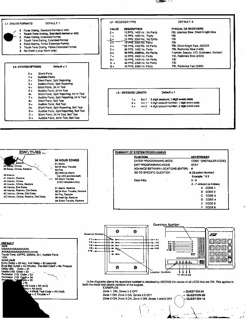
L 1 DIALER FORMATS DEFAULT: 1 Enter the digit for the desired dialer format from the chart below in location Ll ;
0 Pulse Dialing, Standard Format or 4X2 1 Touch Tone Dlallng, Standard format or 4X2 2 Pulse Dialing, Extended Format 3 Touch Tone Dialing, Extended Format 4 Pulse Dialing, Partial Extended Format
.5 Touch Tone Dialing, Partial Extended Format 8 No Dialer (Local Alarm only)
FORMAT EXPLANATIONS Standard Standard format involves a 3 or 4 digit account number followed by a single round event code. Examples:
1233 or 6548 2
Extended Extended format sometimes known as universal or expanded format) transmits two rounds of information. The irst round includes the account number and an exp,ansion character whrle the second t’ round repeats the expansion digit as account number before identifyrng the zone code.
For example; 1233 333 1 Of
4312 E EEEE 7
PARTIAL EXTENDED --Y The partial extended format transmits a standard signal for alarm conditions and an extended message for restores and other system conditions. NOTE: The extended message codes must be B-F).
STAR XL4600 HOOKUP ANti INSTALLATION Page 12
Example: Alarm Condition 853 1
Restore 853 E EEE 1
L2 - RECEIVER TYPE DEFAULT: 6 Enter the digit for the desired receiver type from the chart below in location L2. VALUE DESCRIPTION TYPICAL CS RECEIVERS 0 1:
10 PPS, 1400 Hz., No Parity FBI, Ademco Slow, Silent Knight Slow 10 PPS, 1400 Hz, Parity FBI
2= 10 PPS, 2300 Hz, No Parity FBI 3= 10 PPS, 2300 Hz, Parity FBI 4= 20 PPS, 1400 Hz, No Parity FBI, Silent Knight Fast, ADCOR, ADEMCO 685 5 = 20 PPS, 1400 Hz, Parity FBI, Radionics Slow (1400) 6= 20 PPS, 2300Hz., No Parity Franklin, Sescoa, DCI, Quickalert, Varitech, ADEMCO 685 7 = 20 PPS, 2300 Hz, Parity FBI, Radionics Slow (2300) 8 A==
,40 PPS, 1400 Hz, No Parity FBI 40 PPS, 2300 Hz, No Parity FBI
B= 40 PPS, 2300 Hz, Parity FBI, Radionics Fast (2300) NOTE: For UL installations the acceptable receivers are FBI CP220 (all formats), ADEMCO 685 (all formats without parity), Silent Knight 8520 or 9000.
L3 - MESSAGE LENGTH / BELL LOCKOUT Default q 1 Enter the digit for the desired message length from the chart below in location L3.
l= 3 x 1 3 dlglt account, 1 dlglt event code, no bell lockout 9 = 3x1, with bell lockout 2= 4 x 1 4 digit account number, 1 digit event code, no bell lockout A = 4x1, with bell lockout 4 4 x 2 4 digit account number, 2 digit event code, no bell lockout C = 4x2, with bell lockout
If bell lockout itselected then subsequent activations of the same zone within the same arming interval will not activate the bell. This applies only to burglary (non 24 hour) zones. For UL installations bell lockout must not be selected.
NOTE: Please consult your Central Station manager to determine the formats message lengths which are accepted by the receiver.
L4- SYSTEM OPTIONS Default = 1 Enter the digit for the desired system options from the chart below in location L4. o=
l= 2 = 3 4: 5.Z 6= 7= 8= 9= A= B= C= D= E= F=
Silent Panic Audtble Panic Silent Panic, Split Reporting Audible Panic, Split Reporting Silent Panic, 24 Hr Test Audible Panic, 24 Hr Test Silent Panic, Split Reporting, 24 Hr Test Audible Panic, Split Reporting, 24 hr Test Silent Panic, Bell Test Audible Panic, Bell Test Silent Panic, Split Reporting, Bell Test Audible Panic, Split Reporting, Bell Test Silent Panic, 24 Hr Test, Bell Test Audible Panic, 24 hr Test, Bell Test Silent Panic, Split Reporting, 24 Hr Test, Bell Test Audible Panic, Split Reporting, 24 Hr Test, Bell Test
STAR XL4600 HOOKUP AND INSTALLATION Page 13
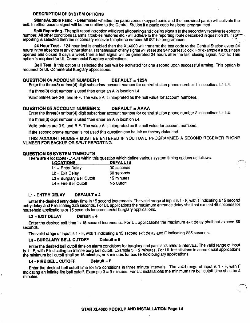
DESCRIPTION OF SYSTEM OPTIONS Silet’WAudlbie Panic - Determines whether the panic zones (keypad panic and the hardwired panic) will activate the
bell. In either case a signal will be transmitted to the Central Station if a panic code has been programmed. Split Reporting -The split reporting option will direct all opening and closing signals to the secondary receiver telephone
number. All other conditions (alarms, troubles restores etc.) will adhere to the reporting route described in question 01 .If spl-\ reporting is selected then the secondary receiver telephone number MUST be programmed. hP{
‘1- ,’ 24 Hour Teat - If 24 hour test is enabled then the XL4600 will transmit the test code to the Central Station every 24
hours in the absence of any other signal. Transmission of any signal will reset the 24 hour test clock. For example if a business opened and closed 6 days a week then a test signal will be generated. 24 hours after the last closing signal. NOTE: This option is required for UL Commercial Burglary applications.
Bell Teat If this option is selected the bell will be activated for one second upon successful arming. This option is required for UL Commercial Burglary applications.
QUESTION 04 ACCOUNT NUMBER 1 DEFAULT = 1234 Enter the three(3) or four(4) digit subscriber account number for central station phone number 1 in locations Ll -L4. If a three(3) digit number is used then enter an A in location L4. Valid entries are O-9, and B-F. The value A is interpreted as the null value for account numbers.
QUESTION 05 ACCOUNT NUMBER 2 DEFAULT = AAAA Enter the three(3) or four(4) digit subscriber account number for central station phone number 2 in locations Ll-L4. If a three(3) digit number is used then enter an A in location L4. Valid entries are O-9, and B-F. The value A is interpreted as the null value for account numbers. If the second phone number is not used this question can be left as factory defaulted. THIS ACCOUNT NUMBER MUST BE ENTERED IF YOU HAVE PROGRAMMED A SECOND RECEIVER PHONE
NUMBER FOR BACKUP OR SPLIT REPORTING.
QUESTION 06 SYSTEM TIMEOUTS There are 4 locations (Ll-L4) within this question which define various system timing options as follows:
CATIONS DEFAUI TS Ll = Entry Delay 30 seconds L2 = Exit Delay 60 seconds L3 = Burglary Bell Cutoff 15 minutes L4 = Fire Bell Cutoff No Cutoff
rl
Ll - ENTRY DELAY DEFAULT = 2 Enter the desired entry delay time in 15 second increments. The valid range of input is 1 - F, with 1 indicating a 15 second
entry delay and F indicating 225 seconds. For UL applications the maximum entrance delay shall not exceed 45 seconds for household applications or 15 seconds for commercial burglary applications.
L2 - EXIT DELAY Default q 4 Enter the desired exit time in 15 second increments. For UL applications the maximum exit delay shall not exceed 60
seconds. The valid range of input is 1 - F, with 1 indicating a 15 second exit delay and F indicating 225 seconds. L3 - BURGLARY BELL CUTOFF Default = 5 Enter the desired bell cutoff time on alarm conditions for burglary and panic in 3 minute’intervals. The valid range of input
is 1 - F, with F indicating an infinite burg bell cutoff. Example 3 = 9 minutes. For UL installations in commercial applications the minimum bell cutoff shall be 15 minutes, or 4 minutes for house hold burglary applications.
L4 - FIRE BELL CUTOFF Default = F Enter the desired bell cutoff time for fire conditions in three minute intervals. The valid range of input is 1 - F, with F
indicating an infinite fire bell cutoff. Example 3 = 9 minutes, For UL installations the minimum fire bell cutoff time shall be 4 minutes.
STAR XL46WHOOKUP AND INSTALLATION Page 14
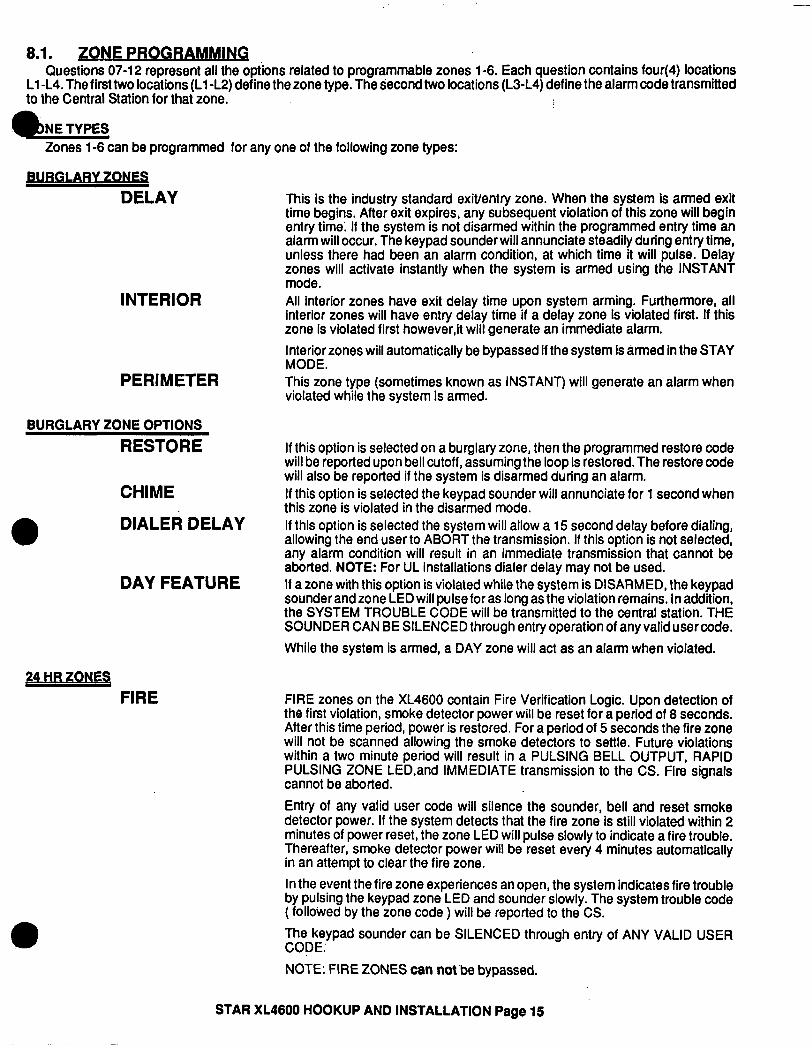
8.1. ZONE PROGRB Questions 07-l 2 represent all the options related to programmable zones l-6. Each question contains four(4) locations
Ll -L4. The first two locations (Ll -L2) define the zone type. The second two locations (L3-L4) define the alarm code transmitted to the Central Station for that zone.
Zones l-6 can be programmed for any one of the following zone types:
RY 7oNEs
DELAY
INTERIOR
PERIMETER
BURGLARY ZONE OPTIONS RESTORE
CHIME
DIALER DELAY
DAY FEATURE
?4 “R ZONEQ FIRE
This is the industry standard exit/entry zone. When the system is armed exit time begins. After exit expires, any subsequent violation of this zone will begin entry time; If the system is not disarmed within the programmed entry time an alarm will occur. The keypad sounder will annunciate steadily during entry time, unless there had been an alarm condition, at which time it will pulse. Delay zones will activate instantly when the system is armed using the INSTANT mode. All interior zones have exit delay time upon system arming. Furthermore, all interior zones will have entry delay time if a delay zone is violated first. If this zone is violated first however,it will generate an immediate alarm. Interior zones will automatically be bypassed if the system is armed in the STAY MODE. This zone type (sometimes known as INSTANT) will generate an alarm when violated while the system is armed.
If this option is selected on a burglary zone, then the programmed restore code will be reported upon bell cutoff, assuming the loop is restored. The restore code will also be reported if the system is disarmed during an alarm. If this option is selected the keypad sounder will annunciate for 1 second when this zone is violated in the disarmed mode. If this option is selected the system will allow a 15 second delay before dialing, allowing the end user to ABORT the transmission. If this option is not selected, any alarm condition will result in an immediate transmission that cannot be aborted. NOTE: For UL installations dialer delay may not be used. If a zone with this option is violated while the system is DISARMED, the keypad sounder and zone LED will pulse for as long as the violation remains. In addition, the SYSTEM TROUBLE CODE will be transmitted to the central station. THE SOUNDER CAN BE SILENCED through entry operation of any valid user code. While the system is armed, a DAY zone will act as an alarm when violated.
FIRE zones on the XL4600 contain Fire Verification Logic. Upon detection of the first violation, smoke detector power will be reset for a period of 6 seconds. After this time period, power is restored. For a period of 5 seconds the fire zone will not be scanned allowing the smoke detectors to settle. Future violations within a two minute period will result in a PULSING BELL OUTPUT, RAPID PULSING ZONE LED,and IMMEDIATE transmission to the CS. Fire signals cannot be aborted.
Entry of any valid user code will silence the sounder, bell and reset smoke detector power. If the system detects that the fire zone is still violated within 2 minutes of power reset, the zone LED will pulse slowly to indicate a fire trouble. Thereafter, smoke detector power will be reset every 4 minutes automatically in an attempt to clear the fire zone. In the event the fire zone experiences an open, the system indicates fire trouble by pulsing the keypad zone LED and sounder slowly. The system trouble code ( followed by the zone code ) will be reported to the CS. The keypad sounder can be SILENCED through entry of ANY VALID USER CODE.’
NOTE: FIRE ZONES can not be bypassed.
STAR XL4600 HOOKUP AND INSTALLATION Page 15
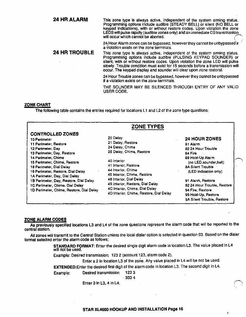
24 HR ALARM This zone type is always active, independent of the system arming status. Programming options include audible (STEADY BELL) or silent (NO BELL or keypad indications), with or without restore codes. Upon violation the zone LEDS will pulse rapidly (audible zones only) and an immediate CS transmission will occur which cannot be aborted.
c; 24 Hour Alarm zones can be bypassed, however they cannot be unbypassed’ir ’ a \iiolation exists on the zone terminals.
24 HR TROUBLE This zone type is always active, independent of the system arming status. Programming options include audible (PULSING KEYPAD SOUNDER) or silent, with or without restore codes. Upon violation the zone LED will pulse slowly. Trouble condition must exist for 15 seconds before a transmission will occur. The keypad display and sounder will clear upon zone restoral. 24 Hour Trouble zones can be bypassed, however they cannot be unbypassed if a violation exists on the zone terminals. THE SOUNDER MAY BE SILENCED THROUGH ENTRY OF ANY VALID USER CODE.
ZONE CHART The following table contains the entries required for locations Ll and L2 of the zone type questions;
CONTROLLED ZONES 10 Perimeter 11 Perimeter, Restore 12 Perimeter, Day 13 Perimeter, Day, Restore 14 Perimeter, Chime 15 Perimeter, Chime, Restore 18 Perimeter, Dial Delay 19 Perimeter, Restore, Dial Delay 1A Perimeter, Day, Dial Delay 1 B Perimeter, Day, Restore, Dial Delay 1C Perimeter, Chime. Dial Delay 1 D Perimeter, Chime, Restore, Dial Delay
ZONE TYPES
20 Delay 21 Delay, Restore 24 Delay, Chime 25 Delay, Chime, Restore
40 Interior 41 Interior, Restore 44 Interior, Chime 45 Interior, Chime, Restore 48 Interior, Dial Delay 49 Interior, Restore, Dial Delay 4C Interior, Chime, Dial Delay 4D Interior, Chime, Restore, Dial Delay
24 HOUR ZONES 81 Alarm 82 24 Hour Trouble 84 Fire 89 Hold-Up Alarm
(no LED,sounder,bell) 8A Silent Trouble
(LED indication only)
91 Alarm, Restore 92 24 Hour Trouble, Restore 94 Fire, Restore 99 Hold-Up, Restore 9A Silent Trouble, Restore
rl
ZONE ALARM CODES As previously specified locations L3 and L4 of the zone questions represent the alarm code that will be reported to the
centraistation. All zones will transmit to the Central Station unless the local dialer option is selected in question 03. Based on the dialer
format selected enter the alarm code as follows; STANDARD FORMAT: Enter the desired single digit alarm code in location L3. The value placed in L4 will not be used. Example: Desired transmission 123 2 (account 123, alarm code 2).
Enter a 2 in location L3 of the zone. Any value placed in L4 will be not be used. EXTENDED:Enter the desired first digit of the alarm code in location L3. The second digit in L4. Example: Desired transmission 123 3
333 4 Enter 3 in L3,4 in L4. r? \ \
STAR XL4600 HOOKU’P AND INSTALLATION Page 16
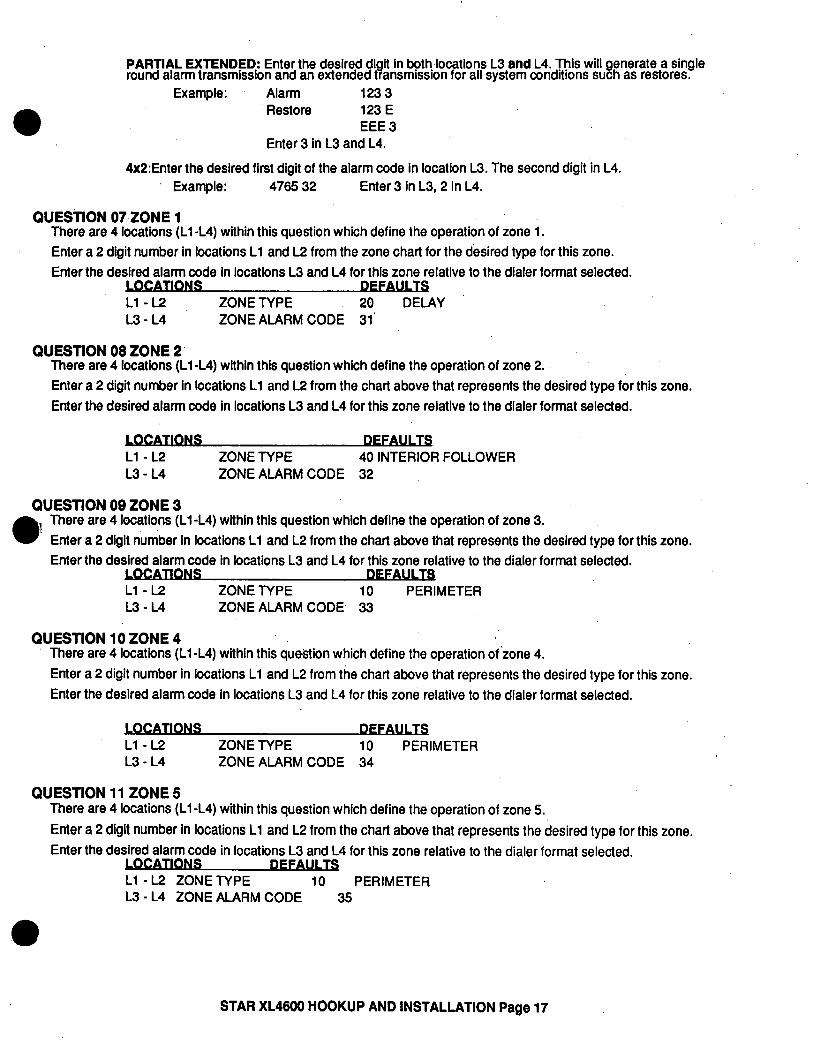
PARTlAL EXTENDED: Enter,the desired digit in both locations L3 and L4. This will generate a single round alarm transmission and an extended transmission for all system conditions such as restores.
Example: Alarm 1233 Restore 123 E
EEE 3 Enter 3 in L3 and L4.
4xZ:Enter the desired first digit of the alarm code in location L3. The second digit in L4. . Example: 4765 32 Enter 3 in L3,2 in L4.
QUESTION 07,ZONE 1 There are 4 locations (Ll-L4) within this question which define the operation of zone 1. Enter a 2 digit number in locations Ll and L2 from the zone chart for the desired type for this zone. Enter the desired alarm code in locations L3 and L4 for this zone relative to the dialer format selected.
CATUS DEFU Ll - L2 ZONE TYPE 26 DELAY L3 - L4 ZONE ALARM CODE 31’ .
QUESTION 08 ZONE 2 There are 4 locations (Ll -L4) within this question which define the operation of zone 2. Enter a 2 digit number in locations Ll and L2 from the chart above that represents the desired type for this zone. Enter the desired alarm code in locations L3 and L4 for this zone relative to the dialer format selected.
CATIDNS WAUl TS Ll - L2 ZONE TYPE 40 INTERIOR FOLLOWER L3 - L4 ZONE ALARM CODE 32
QUESTION 09 ZONE 3 There are 4 locations (Ll-L4) within this question which define the operation of zone 3. Enter a 2 digit number in locations Ll and L2 from the chart above that represents the desired type for this zone. Enter the desired alarm code in locations L3 and L4 for this zone relative to the dialer format selected.
Ll - L2 ZONE TYPE IO L3 - L4 ZONE ALARM CODE, 33
PERIMETER
QUESTION 10 ZONE 4 There are 4 locations (Ll-L4) within this question which define the operation of ‘zone 4. Enter a 2 digit number in locations Ll and L2 from the chart above that represents the desired type for this zone. Enter the desired alarm code in locations L3 and L4 for this zone relative to the dialer format selected.
Ll - L2 L3 - L4
ZONE TYPE 10 PERIMETER ZONE ALARM CODE 34
QUESTION 11 ZONE 5 There are 4 locations (Ll -L4) within this question which define the operation of zone 5. Enter a 2 digit number in locations Ll and L2 from the chart above that represents the desired type for this zone. Enter the desired alarm code in locations L3 and L4 for this zone relative to the dialer format selected.
Ll - L2 ZONE TYPE 10 PERIMETER L3 - L4 ZONE ALARM CODE 35
STAR XL4600 HOOKUP AND INSTALLATION Page 17
QUESTION 12 ZONE S There are 4 locations (Ll-L4) within this question which define the operation of zone 6. Enter a 2 digit number in locations Ll and L2 from the zone chart that represents the desired type for this zone. Enter the desired alarm code in locations L3 and L4 for this zone relative to the dialer format selected.
LOCATIONS DEFAULTS Ll -L2 ZONE TYPE 84 FIRE L3-L4 ZONE ALARM CODE 16
QUESTION 13 AMBUSH/AC LOSS There are 4 locations Ll-L4 in this question. Li - L2 is the alarm code that will be transmitted on AMBUSH. L3 - L4 is the
AC LOSS CODE. The same rules for programming regarding dialer format apply here. If either, or both of these transmissions are not desired; program their respective locations AA AMBUSH transmissions are immediate and not abortable. AC LOSS transmissions will be reported 15 minutes after detection.
CATIONS OEFAU1 TS Ll -L2 AMBUSH AA 13-L4 AC LOSS AA
QUESTlON 14 PANIC/LOW BATTERY There are 4 locations Cl-L4 in this question. Ll - L2 is the alarm code that will be transmitted on PANIC. This code will
be transmitted for KEYPAD as well as HARDWIRE PANIC. L3 - L4 is the LOW BATTERY CODE. The same rules for programming regarding dialer format apply here. if either or both of these transmissions are not desired, program their respective locations AA PANIC transmissions are immediate and not abortable. LOW BATTERY transmissions will be reported 4 minutes after detection. LOW BATTERY RESTORE CODE will be
reported WITHIN 4 minutes after detection of GOOD BATTERY condition.
Li-L2 PANIC L3 - L4 LOW BATTERY
22 ‘(-7 AA _’
QUESTION 16 OPEN/CLOSE,24 HRTEST CODE There are 4 locations Ll-L4 in this question. Ll is the single digit OPENING CODE. L2 is the single digit CLOSING CODE. Entry of AA into these two locations means
, that openings and closings are not desired. If a dialer format other than standard is programmed then the second digit transmitted will be the user number.
L3 - L4 is the 24 HR TEST CODE. Entry of AA means that 24 hour test is not enabled. If 24 hour test code is selected then ANY valid transmission will reset the 24 hour test timer.
TIONS Ll OPENING CODE A L2 CLOSING CODE A L3 - L4 24 HR TEST AA
QUESTlON 16 BYPASS/RESTORE/TROUBLE/FUTURE There are four(4) locations Ll - L4 in this question Ll is the single digit system BYPASS CODE that will be reported to the central station if a zone is bypassed, UPON
ARMING.Entry of an A means that bypasses are not transmitted. If a two digit dialing format has been selected then the Bypass code will be followed by the programmed second digit of the zones code.
L2 is the single digit system RESTORE CODE reported to the central station. Restores will be reported for burglary or 24 hour zones which have been programmed with the restore option. Entry of an A means that restores are not transmitted. If a two digit dialer format has been programmed then the restore code will be followed by the programmed second digit of the zones code.
L3 is the single digit system TROUBLE CODE reported to the central station. This code will be reported on DAY TROUBLF and any FIRE TROUBLE. If a two digit format has been programmed then this code will be followed by the second digit;3 the respecttve zones code.
L4 is a spare location at this time that may be used in the future.
STAR XL4800 HOOKUP AND INSTALLATION Page 18
CATIONS Ul TS Ll BYPASS A L2 RESTORE A
- L3 TROUBLE F
b L4 SPARE/FUTURE A ll estion 00 INSTALLER CODE There are 4 locations Ll - L4 in this question. Enter any 4 digit (O-9 installer code desired. This code is used to ENTER the system programming mode via the keypad. Typically each installing company would use;a unique installer code in order to prevent unauthorized people from gaining
access to their panels. Note: The factory default value for the installer code is 4600 in locations Ll-L4 respectively.
9 n DATA ENTRY VIA KEYPAD
This section describes the physical keystrokes necessary to perform keypad programming and how to interpret the data dis played on the keypad during programming operations.
Actual keypad programming should be performed after completion of the programming sheet.
9.1. HOW TO ENTER PROGRAMMING MODE The SYSTEM programming mode can be entered WHILE DISARMED ONLY as follows:
DEPRESS the CODE button. DEPRESS the l button. (asterisk) ENTER the four digit INSTALLER CODE (default = 4600)
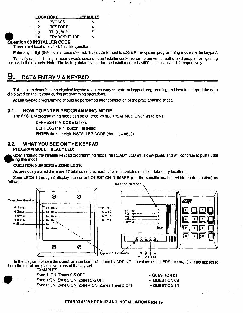
9.2. WHAT YOU SEE ON THE KEYPAD PROGRAM MODE q READY LED: Upon entering the installer keypad programming mode the READY LED will slowly pulse, and will continue to pulse until ving this mode. QUESTION NUMBERS q ZONE LEDS: As previously stated there are 17 total questions, each of which contains multiple data entry locations. Zone LEDS 1 through 5 display the current QUESTION NUMBER (not the specific location within each question) as
follows: Ouestion Number ,
/ c3 M. @
Question Number I +1=-o +2=4-.-o +4=--o +8=--o
+16=--o
co!w’ +1 +2 +3+4
In the diagrams above the question number is obtained by ADDING the values of all LEDS that are ON. This applies to both the metal and plastic versions of the keypad.
EXAMPLES: Zone 1 ON, Zones 2-5 OFF = QUESTION 01 Zone 1 ON, Zone 2 0N;Zones 3-5 OFF = QUESTION 03 Zone 2 ON, Zone 3 ON, Zone 4 ON, Zones 1 and 5 OFF = QUESTION 14
STAR XL4900 HOOKUP AND INSTALLATION Page 19
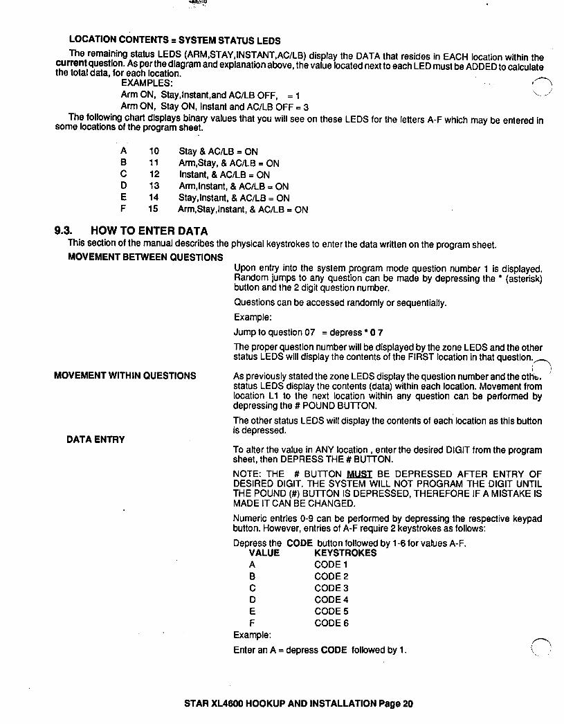
LOCATION CONTENTS q SYSTEM STATUS LEDS The remaining status LEDS (ARM,STAY,INSTANT,AC/LB) display the DATA that resides in EACH location within the
current question. As per the diagram and explanation above, the value located next to each LED must be ADDED to calculate the total data, for each location. -
EXAMPLES: <’ Arm ON, Stay,lnstant,and AC/LB OFF, = 1
1 \,
Arm ON, Stay ON, Instant and AC/LB OFF = 3 The following chart display8 binary values that you will see on these LEDS for the letters A-F which may be entered in
some locations of the program sheet.
A 10 Stay & AC/LB = ON B 11 ArmStay, & AC/LB = ON C 12 Instant, &AC/LB = ON D 13 ArmInstant, & AC/LB = ON E 14 StayJnstant, &AC/LB = ON F 15 Arm,Stay,lnstant, &AC/LB = ON
9.3. HOW TO ENTER DATA This section of the manual describes the physical keystrokes to enter the data written on the program sheet. MOVEMENT BETWEEN QUESTIONS
Upon entry into the system program mode question number 1 is displayed. Random jumps to any question can be made by depressing the l (asterisk) button and the 2 digit question number.
Questions can be accessed randomly or sequentially. Example: Jump to question 07 = depress l 0 7 The proper question number will be displayed by the zone LEDS and the other status LEDS will display the contents of the FIRST location in that question.
As previously stated the zone LEDS display the question number and the othb, ’ status LEDS display the contents (data) within each location. Movement from location Ll to the next location within any question can be performed by depressing the # POUND BUTTON.
MOVEMENT WITHIN QUESTIONS
DATA ENTRY
The other status LEDS will display the contents of each location as this button is depressed.
To alter the value in ANY location , enter the desired DIGIT from the program sheet, then DEPRESS THE # BUTTON. NOTE: THE # BUTTON JVlUST BE DEPRESSED AFTER ENTRY OF DESIRED DIGIT. THE SYSTEM WILL NOT PROGRAM THE DIGIT UNTIL THE POUND (#) BUTTON IS DEPRESSED, THEREFORE IF A MISTAKE IS MADE IT CAN BE CHANGED. Numeric entries O-9 can be performed by depressing the respective keypad button. However, entries of A-F require 2 keystrokes as follows: Depress the CODE button followed by l-6 for values A-F.
VALUE KEYSTROKES A CODE 1 B CODE 2 C CODE 3 D CODE 4 E CODE 5 F CODE 6
Example: Enter an A = depress CODE followed by 1.
STAR XL4600 HOOKUP AND INSTALLATION Page 20
,, ”
EXfT SYSTEM PROGRAM MODE
J ~
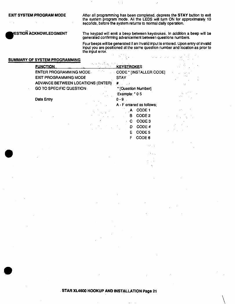
After all programming has been completed, d8preS8 the STAY button to exit the system program mode. All the LEDS.will turn ON for approximately, 10 seconds, before the system returnsto normal daily operation.
w ESTlOfi‘hCKNOWLEDGMENT The keypad will emit a beep between keystrokes. In addition. a beep will be
generated confirming advancement between questions numbers. Four beeps will be generated if an invalid input is entered. Upon entry of invalid input you are positioned at the same question number and location as prior to the input error.
/, “, ..,. .: ‘I. SUMMARY OF SYSTEM PROGRAMMING ,: ., I
‘, r ‘. .,,. ‘-I, :, FUNCTION KEYSTROKES : I. ENTER PROGRAMMING MODE. ‘. CODE’[INSTALLER,CODE] : :. EXIT PROGRAMMING MODE STAY
,.
ADVANCE BETWEEN LOCATIONS (ENTER!’ ,#, /
,. ! ; GO TO SPECIFICQUESTION. “[Question Number]
‘Example: l 0 5 L.,” .’ ,I,
Data Entry o,-9 : A - F entered as follows;
” ,A CODE1 : ,: . B CODE2 ‘,
.: C CODE3 .‘. D CODE4
” E CODE5 : i
F CODE6
STAR XL4600 HOOKUP AND INSTALLATION Page 21
\
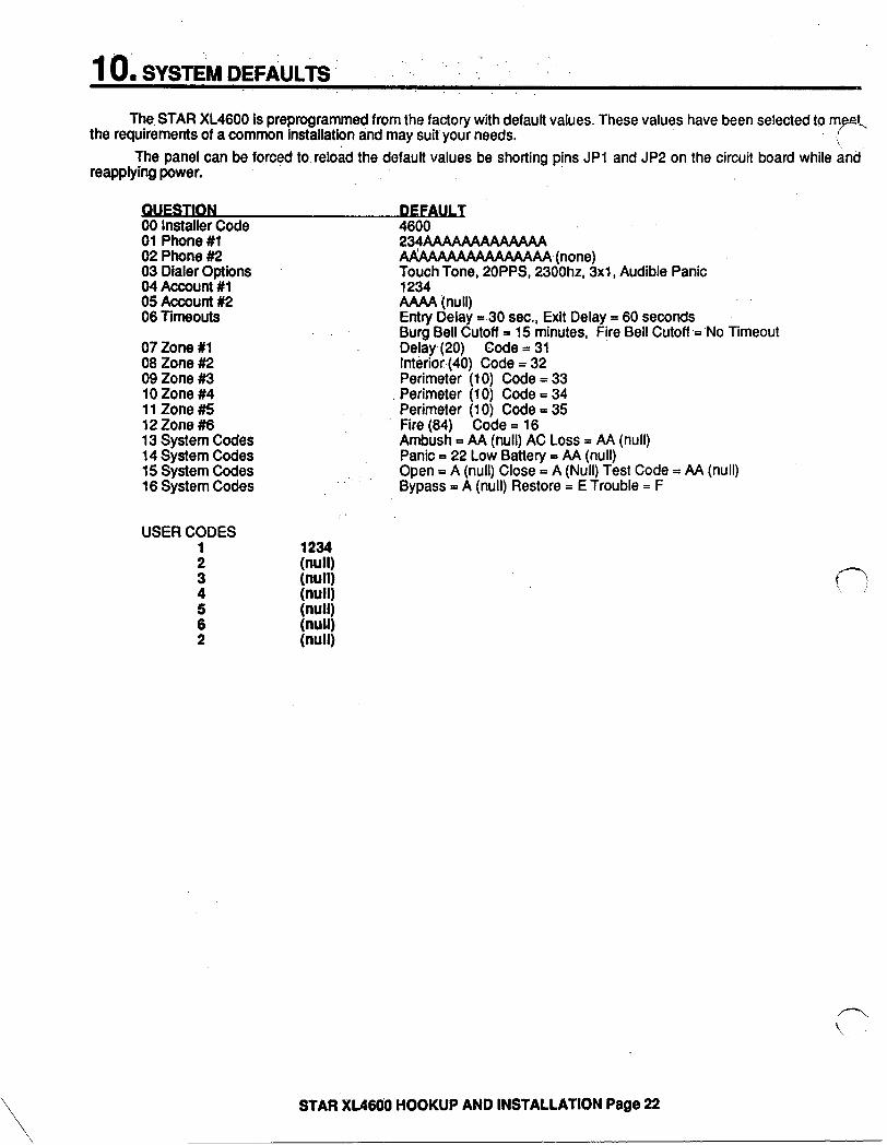
The STAR XL4600 is preprogrammed from the factory with default values. These values have been selected to rn,eei, the requirements of a common installation and may suit your needs.
The panel can be forced to.reload the default values be shorting pins JPl and JP2 on the circuit board while and reapplying power.
00 Installer Code 01 Phone ##l 02 Phone ##2 03 Dialer Options 04 Account #l 05 Accoutll#2 06 -f-hWOUtS
07 zone #l 08 Zone #2 09 Zone #3 lOZone##4 11 Zone #5 12Zone#6 13 System Codes 14 System Codes 15 System Codes 18 System Codes
USER CODES
:
3
f 2
4800 ., 234AWWWWWW AAAAAAAAAAAAAAAA (none) Touch Tone, POPPS, 2300hz, 3x1, Audible Panic 1234 AMA (null) Entry Delay = 30 sec., Exit Delay = 60 seconds Burg Bell Cutoff = 15 minutes, Fire Bell Cutoff ,=‘No Timeout Delay (20) Code = 31 Interior (40) Code = 32 Perimeter (10) Code = 33 Perimeter (10) Code = 34 Perimeter (10) Code = 35 Fire (84) Code = 16 Ambush = AA (null) AC Loss = AA (null) Panic = 22 Low Battery = AA (null)
..’ Open = A (null) Close = A (Null) Test Code = AA (null) Bypass = A (null) Restore = E Trouble = F
\ \
STAR XL4606 HOOKUP AND INSTALLATION Page 22

STAR XL4600 PROGRAMMING WORKSHEET ”
Primary Telco. Number oooooooooooooooc-: Ll L2 L3 L4 L5 L6 L7 L8 L9 LlO Lll L12 L13 L14 Ll5 L16
02 Secondary Telco. Number 0000000000000000 Ll L2 L3 L4 L5 L6 L7 L8 L9 LlO Lll L12 L13 L14 L15 L16
03 Dialer Information
04 Account Number 1
05 Account Number 2
06 System Timeouts
[7nnr]
FokJat kc: k$ L4 Mist
0000 .TJ$yd bfit L3 L4
3 or 4 Digit
0000
07 Zone 1
08 Zone 2
Zone Type CS Code
Zone Type mm
09
10
‘I 1
Zone 3
Zone 4
Zone5 ~ Z&e Ty
,ne Type CS Code
13 Ambush/AC Loss mbush AC LOSS
3 CS Code
II. I CONTROLLU) ZONE&‘-t . 10 Perimeter f ‘.
1, Perim*or. Restore 12 Pwtmetor. Day 13 Pwimotor. Day. Rostoro 14 Perimeter. Chime 15 Perimeter. Chime. Restore 16 Perimeter. Diil Delay 19 Perimeter. Restore. Diil Delay 1A Perimeter. Day,,Oinl Doby I B Porlmotec. Day, Restore. Dial Delay 1C Perimeter. Chime. Dial Delay 1 D Perimeter. Chk. Restore, Dial Dolay
* c LI L< 4cI? f SYSTEM DEFAULTS
Panic 4 ‘2 La L4
Low Battery
Open Close T . esr
1 pl#
z TyGbzare BYP&
06 IDF . 1 .=;; ,,-2 L3 L4 Ll L
/ ./
00 Installer Code 01 PhOne I1 “3 Ptnna w
I 04 Accourtl II
I I I LVIIW 1.J 12ZoneU6 ‘(,
I 14 System codes
I
15 Svstem codes 16 t&tern Codes
I - - . .-. - ., - 03 Oiler Optbns
05 Accounl112 - 06 Tinteouts
07 Zone #I 06 Zone Iy2 09 Zone IM 10ZoneM - . . 7rrsuc / -..
I 13 System Codes
14 Panic/Low Battery
15 Open Close Test
16 Bypass Restore Trouble
00 Installer Code 4 ulglr
L
L 1 DIALER FORMATS DEFAULT: 1
p 0 Puke Dialing, Slandard Formal or 4X2 1 Touch Tone Dlallng, Slanderd formal or 4X2
*“. 2 Puke Dklkg, Extended Formal 3 Touch Tone Dialing, Extended Fortnat 4 Pulse Dialing, Partial Extended Format 5 Touch Tone Dialing, Parlial Extended Format 8 No Diakr (Local Alarm only)
I L2 - RECEWER TYPE DEFAULT: 6
L4- SYSTEM OPTIONS Default t 1
O- li 2- 3- 4= 5. 6- 7. a= 9. A= B. C- o-
Silent Panic Audible Panic Silent Panic. Split Reponing Audible Panic, Splil Repodlng Silent Panic, 24 Hr Test Audiile Panic, 24 Hr Test Silent Park. Split Reporting. 24 Hr TeSt Audible Panic, SpM Reporting, 24 hr TeSl Silent Panic, Sell Test Audible Panic, Bell Tefd Silent Panic, Splil Reporllng. Sell Teal Audible Panic, Split Reporting, Sell Tesl Silent Panic, 24 Hr Test. Bell Test Audible Panic. 24 hr Teal. Sell Test
VALUE O- 1.
DESCRIPTION 10 PPS, 1400 Hz, No Parity 10 PPS. 1400 HZ. PaMy 10 PPS, 2300 HZ. N6.&vily
Pity 1 /20 PPS. 1400 lk, No Parity
20 PPS. 1400 Hz, Parity 20 PPS, 23OWz.. No Parlly 20 PPS, 2300 Hz, Parity
TYPICAL CS RECEIVERS FBI, Ademco Slow, Silent Knight Slow FBI FBI FBI FBI, Silent Knight Fast, ADCOR FBI. Radionics Slow (1400) Franklin, Sesooa. DCI, Quickalert. Varitech FBI. Radionics Slow (2300)
6. 40 PPS, 1400 HZ. No Parity FBI A. 40 PPS, 2300 fiz. No Parity FBI B. 40 PPS, 2300 Hz. Parity FBI, Radionics Fast (2300)
L3 - MESSAGE LENGTH Default D 1
15 3 x 1 ‘3 dlglt account, 1 dlgll event code 2- 4.x 1 ’ 4 diiir accounl number, 1 digis ever-4 a& 4. 4.x 2 + 4 digit account rnrrnber, 2 d~il ever4 code
40 Interior ~\. 41 Interior. Restore 44 Imorior, Chime 45 Inlotir. Chime. Rosloro 48 Inlerior. Diil Dslay 49 Interior. Restore. Dial Delay 4C Interior. Chime. Diil D&y 4D Interior. Chime. Restore. Dial D&y
irl HOUR ZONES 81 Alarm
A 92 24 Hour Tmublo 84 Fire. ~$+~kt-Up Alarm
(no LED.soundor.bsll) -- eA Silent Tmuble
(LED indicakn only)
91 Alarm, Restore 92 24 Hour Trouble. Restore 94 Fire. Restore 99 Hold-Up. Rssiore 9A Silent Tmublo. Restore
Quaslim Number
1 +1.- +2=-
234AAAAAAAAAAAAA AAAAAAAAAAAAAAAA (none) Touch Tone, POPPS. 23oOhz, 3x1, Audible Panic 1234 .-_. two) Eniry Delay - 30 eec.. Exit Delay - 60 seconds Burg Bell Cutoll I 15 rnlnutes. Fire Bell Cutoft= No Timeout Delay (20) code - 31 InIedor(40) Code=32 b. Perimeter (10) Code --,u’ \ Perimeter (10) C&i-34
+4=- +0=-
l 1e -c-
c
SUMMARY OF SYSTEM PROGRAMMING
NNCTlaNKEYSTROKES ENTER PROGRAMMING MODE CODE l [INSTALLER CODE) EXIT PROGRAMMING MODE STAY ADVANCE BETWEEN LOCATIONS (ENTER) C GO TO SPECIFIC OUkTlON r(Guestbn Numbarj
Example:‘05 Data Eniry o-9
A - F entered as follow& A CODE1 B CODE2 C CODE3 D CODE4 E CODE5 F CODE6
10 Ouestto; Number ,,, r
>’
I .a..- =+1 .* OS%. -- -+2
I .r 1, =+4 .a .ue - es ‘7
Yl
=*a
0. .w
\
0 0 Location
In the diagrams above the questlon number is obtained by ADDING the values 01 all LEDS that are ON. This applies to bath the metal a;dgJic;rions 01 the keypad.
Zone 1 ON,‘Zones 2-5 OFF = QUESTION 01
.
E Trouble I F
1 Zone Zone 2 1 ON, ON, Zone Zone 2 3 ON, ON, Zones Zone 4 3-5 OFF ON, Zones 1 and 5 OFF \= QUESTION 14
FBI Limited Warranty
Fire Burglary instruments, Inc., its parents, subsidiaries, divisions and affiliates (“Seller”) warrants its products to be in conformance with its own plans and specifications and to be free from defects in materials and workmanship under normal use and service for 18 months from the date stamp control on the product, or for products not having a date stamp, for 12 months from date of original purchase unless the installation instructions or catalog sets forth a shorter period, in which case the shorter period shall apply. Seller’s obligation shall be limited to repairing or replacing, at its option, free of charge for materials or labor, any part which is proved not in compliance with Seller’s specifications or proves defective in materials or workmanship under normal use and service. Seller shall have no obligation under this Limited Warranty or otherwise, if the product is altered or improperly repaired or serviced by anyone other than Seller. For warranty service, return product transportation prepaid, to Factory Service, 163 Eileen Way, Syosset, New York 11791.
THERE ARE NO WARRANTIES, EXPRESS OR IMPLIED, OF MERCHANTABILITY, OR FITNESS FOR A PARTIC- ULAR PURPOSE OR OTHERWISE, WHICH EXTEND BEYOND THE DESCRIPTION ON THE FACE HEREOF. IN NO CASE SHALL SELLER BE LIABLE TO ANYONE FOR ANY CONSEQUENTIAL OR INCIDENTAL DAMAGES FOR BREACH OFTHIS OR ANY OTHER WARRANTY, EXPRESS OR IMPLIED, OR UPON ANY OTHER BASIS OF LIABILITY WHATSOEVER, EVEN IF THE LOSS OR DAMAGE IS CAUSED BY ITS OWN NEGLIGENCE OR FAULT
Seller does not represent that the products it sells may not be compromised or circumvented; that the products will prevent any personal injury or property loss by burglary, robbery, fire or otherwise; or that the products will in all cases provide adequate warning or protection. Customer understands that a properly installed and maintained alarm may only reduce the risk of a burglary, robbery or fire without warning, but it is not insurance or a guarantee that such will not occur or that there will be no personal injury or property loss as a,result. CONSEQUENTLY, SELLER SHALL-l*AVE NO LIABILITY FOR ANY PERSONAL INJURY, PROPERTY DAMAGE OR OTHER LOSS BASED ON &CLAIM ‘THE PRODUCT FAILED TO GIVE WARNING. However, if Seller is held liable, whether directly or indirectly, for any loss h p5 damage arising under this Limited Warranty or otherise, regardless of cause or origin, Seller’s maximum liabilit,y.s+/all not in any case exceed the purchase price of the product, which shall be the complete and exclusive rempAy against Seller *”
R+ This warranty replaces any previous warranties and is the only warranty made by Seller on this product. No increase or alteration, written or verbal, of the obligations of this Limited Warranty is authorized.