Embed Size (px)
Citation preview
103
Journal of Applied Biomechanics, 2006; 22:103-111. © 2006 Human Kinetics, Inc.
The authors are with the School of Sport and Exercise Sciences, Loughborough University, Ashby Road, Loughborough, Leics. LE11 3TU, U.K.
Landing mats that can undergo a large amount of area deformation are now essential for the safe completion of landings in gymnastics. The objective of this study was to develop an ana-lytical model of a landing mat that reproduces the key characteristics of the mat-ground force during impact with minimal simulation run time. A force plate and two high-speed video cameras were used to record the mat deforma-tion during vertical drop testing of a 24-kg impactor. Four increasingly complex point mass spring-damper models, from a single mass spring-damper system, Model 1, to a 3-layer mass spring-damper system, Model 4, were constructed using Matlab to model the mat’s behavior during impact. A fi fth model composed of a 3-layer mass spring-damper system was developed using visual Nastran 4D. The results showed that Models 4 and 5 were able to match the loading phase of the impact with simulation times of less than 1 second for Model 4 and 28 seconds for Model 5. Both Models 4 and 5 successfully reproduced the key force-time characteristics of the mat-ground interface, such as peak forces, time of peak forces, interpeak minima and initial rates of loading, and could be incorporated into a gymnast-mat model.
Key Words: spring-damper, model, simulation, optimization
Viscoelastic materials are used extensively in sports surfaces which are designed to allow elastic deformation that can enhance performance and
reduce loading. A variety of surfaces have been developed that are commonly assigned to one of two groups: point-elastic surfaces that distribute forces over a small area, and area-elastic surfaces that react to a local force by deforming over a relatively large area. The surface-athlete interaction has been iden-tifi ed as a possible factor that may affect the risk of injury (McNitt-Gray, Yokoi, & Millward, 1994; Peikenkamp, Fritz, & Nicol, 2002), since internal structures may become damaged when loading is too large (Butler, Crowell, & Davis, 2003).
A computer model of a gymnast and landing mat is well suited for examining whether it is pos-sible to alter the landing mat properties to reduce the risk of injury to the gymnast. Injury has been associated with high forces and high rates of load-ing, along with poor alignment of the athlete’s limbs with respect to the landing surface during loading (Frederick, 1984; Nigg, 1985). The poor geometry can arise due to motor errors, fatigue, or unstable surfaces. Research has shown that varying either the material properties of the landing mat or the land-ing strategy adopted by the gymnast can infl uence the ground reaction force (GRF) at the mat-ground interface (Devita & Skelly, 1992; McNitt-Gray, Yokoi, & Millard, 1993; Zatsiorsky & Prilutsky, 1987) and so, presumably, the potential for injury.
A computer model is a simplifi ed representa-tion of the real system and should be suffi ciently complex to answer the research questions. How-ever, increasing model complexity tends to increase simulation time. If a model is to be used to answer specifi c questions using optimization, such as how a gymnast can minimize loading while landing in competition, the simulation time and hence the total
Modeling a Viscoelastic Gymnastics Landing Mat During Impact
Chris Mills, Matthew T.G. Pain, and Maurice R. YeadonLoughborough University
104 Mills, Pain, and Yeadon
time required to perform an optimization may be a critical factor.
If a model of a landing mat is to be used with a model of a gymnast for assessment of injury risk, both accuracy and simulation time are important. A simpler model may allow the simulation to run faster, but it may not be suffi ciently accurate to ascertain the injury risk. More complex models, such as fi nite element models, may have the necessary accuracy but may require much greater simulation time. This may make the optimization of landing mat proper-ties extremely time consuming even though such models may be better able to assess injury risk.
To model a landing mat requires some knowl-edge of the construction and constituent parts, along with results of material tests and the response of the landing mat during subject tests. Landing mats are bulky, have several component layers, trans-mit forces relatively slowly, and undergo large area-viscoelastic deformations. Research has been conducted on elastic surfaces using material tests (Federation Internationale de Gymnastique [FIG], 1996; Francis, Leigh, & Berzins, 1988; McNitt-Gray et al., 1993) and subject tests (De Koning, Nigg, & Gerritsen, 1997; Yeadon & Nigg, 1988). Material tests have usually involved the use of accelerom-eters attached to the mass being dropped and/or a force plate beneath the landing surface (Gatto, Swannell, & Neal, 1992; McNitt-Gray et al., 1993). The masses used have ranged from 5.5 kg (McNitt-Gray et al., 1993) to 20 kg (FIG, 1996) and have been dropped from various heights to assess the cushioning properties of the landing mats. Subject tests have involved the participants dropping from various heights onto the landing mat with force plates used to record the ground reaction forces beneath the mat.
Computer modeling of landing surfaces has ranged from simple linear spring-damper systems and nonlinear spring-damper systems to more com-plex systems (Dura, Garcia, & Solaz, 2002; Gatto et al., 1992). Fritz and Peikenkamp (2003) represented the landing surface using 9 × 9 lumped masses with rotational inertia and fl exible beams connecting the masses horizontally. The most complex models of deformable structures are fi nite element models (FEM) and have been used to model the human spinal column (Ranu, 1989), the foot-shoe interface (Lemmon, Shiang, Hashmi, et al., 1997), and foam crash mats for head impact protection (Lyn & Mills,
2002). However, due to the complexity of FEMs, simulation times can be much longer than for sim-pler models. Additionally, linear FEMs cannot deal with the energy absorption in the foam layers and do not perform as well as nonlinear spring-damper systems when attempting to model the same impact (Lyn & Mills, 2002). It is hypothesized that although the complex mat response to impulse loading is ideally represented by nonlinear FEMs, it can be modeled using simple linear mass spring-damper systems that aim to approximate the physical con-struction of the mat.
The following research questions will be addressed: What is the level of complexity required in a linear mass spring-damper system to accurately model the mat response to impulsive loading? Do increases in model complexity increase simula-tion time such that incorporating more complex models into iterative optimization loops becomes untenable as local optimizations start taking days to converge?
In order for a model to be considered successful, it should be able to match the force time history of the impact. Specifi c key characteristics that should be matched between the model and reality are: the peak forces, the times to peak forces, maximum rates of loading, the fi rst minimum, and the time to fi rst minimum.
Methods
Experimental Data Collection
A custom built impactor consisting of a wooden base and weights fi rmly bolted to a central metal column was dropped vertically onto the center of the sample mat from various heights (1.03 m to 2.15 m), producing measured impact velocities between 4.3 m/s and 6.5 m/s which were within the range of landing velocities reported in the literature (Takei, 1988, 1998). The mass of the impactor was 24 kg and it had a fl at contact area 0.25 m by 0.25 m. The impactor size was designed to match the area covered by an average gymnast’s feet at hip width apart. The mass of the impactor was selected to give the same loading characteristics as a produced by a gymnast when landing on the mat from the same height. A male gymnast (mass 72 kg) performed a competition style landing (minimal deductions as scored by the Federation Internationale de Gym-
A Viscoelastic Gymnastics Landing Mat 105
nastique Code of Points, men’s artistic gymnastics, 2001) onto the sample landing mat from a height of approximately 1.56 m (5.5 m/s vertical impact velocity).
The impactor was released from the same drop height and the mass of the impactor increased with each test until the impulse, vertical force, and rate of force production for the impactor matched the subject test. A Kistler (9281B12) force plate was set to trigger at a level of 25 N with a 10% pretrigger and a collection duration of 5 seconds. Two Phantom (V4.1) high-speed cameras (Vision Research, Inc.), positioned at an angle of 86° to each other, were used to record the mat deformation during impact testing. All data were sampled at 1,000 Hz and were synchronized to within 1 ms.
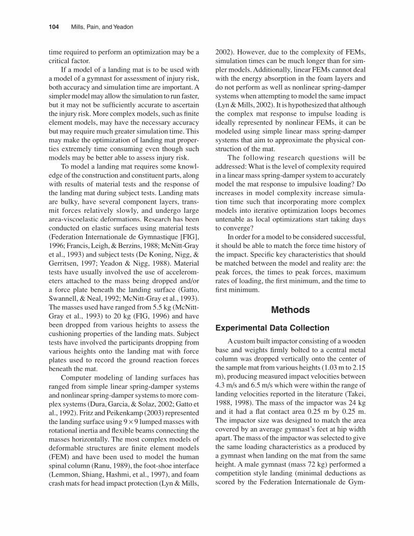
The sample landing mat construction was based on an offi cial FIG competition landing mat and was custom built by the manufacturer (Continental Sports Ltd, Huddersfi eld) for this experiment. The sample landing mat was composed of three layers: the fi rst was a thin (0.005-m) carpet layer, the second was a 0.05-m stiff layer (2.44 kg), and the third a 0.15-m soft layer (3.66 kg). The mat measured 0.90 m long by 0.60 m wide by 0.20 m deep and was surrounded by a custom built wooden frame, which was designed to constrain the landing mat so that it behaved more like a full size landing mat. The
wooden frame was bolted to a rigid frame which in turn was bolted to the force plate to ensure that all forces were transmitted directly to the force plate during impact (Figure 1).
A trial was recorded if the impactor landed fl at on the mat with minimal rotation during impact. This was determined visually and the deviation from the vertical was calculated from the digitized data (mean = 2.6°, SD = 0.87°). Following data collection, a total of fi ve trials representing impact velocities throughout the test range were selected for further analysis. Two additional markers on the impactor were digitized manually to determine the impact velocity for each trial and the maximum vertical displacement of the impactor. The impact velocity for a given trial was determined to within 0.1 m/s. Prior to the impact trials, a calibration structure comprising 20 markers that spanned the volume of the mat were videotaped and digitized. Ten of these calibration points were used to determine the 11 DLT parameters required to reconstruct the 3D coordinates of any markers within the volume. The remaining 10 calibration frame points were used to determine the accuracy of the reconstructed posi-tions. These points were reconstructed to within 1 mm of their measured locations along all three axes using the Matlab program KineMat (Reinschmidt & van den Bogert, 1997).
Figure 1 – Sample landing mat and marker placement.
106 Mills, Pain, and Yeadon
Model Construction
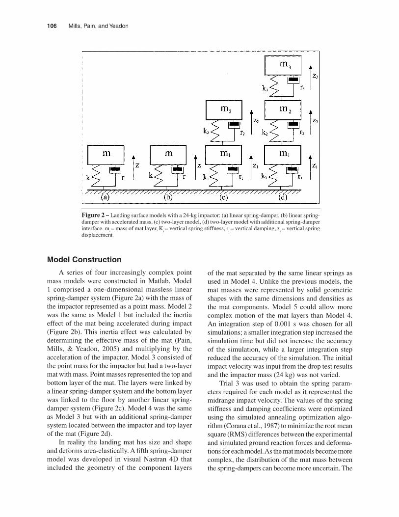
A series of four increasingly complex point mass models were constructed in Matlab. Model 1 comprised a one-dimensional massless linear spring-damper system (Figure 2a) with the mass of the impactor represented as a point mass. Model 2 was the same as Model 1 but included the inertia effect of the mat being accelerated during impact (Figure 2b). This inertia effect was calculated by determining the effective mass of the mat (Pain, Mills, & Yeadon, 2005) and multiplying by the acceleration of the impactor. Model 3 consisted of the point mass for the impactor but had a two-layer mat with mass. Point masses represented the top and bottom layer of the mat. The layers were linked by a linear spring-damper system and the bottom layer was linked to the fl oor by another linear spring-damper system (Figure 2c). Model 4 was the same as Model 3 but with an additional spring-damper system located between the impactor and top layer of the mat (Figure 2d).
In reality the landing mat has size and shape and deforms area-elastically. A fi fth spring-damper model was developed in visual Nastran 4D that included the geometry of the component layers
of the mat separated by the same linear springs as used in Model 4. Unlike the previous models, the mat masses were represented by solid geometric shapes with the same dimensions and densities as the mat components. Model 5 could allow more complex motion of the mat layers than Model 4. An integration step of 0.001 s was chosen for all simulations; a smaller integration step increased the simulation time but did not increase the accuracy of the simulation, while a larger integration step reduced the accuracy of the simulation. The initial impact velocity was input from the drop test results and the impactor mass (24 kg) was not varied.
Trial 3 was used to obtain the spring param-eters required for each model as it represented the midrange impact velocity. The values of the spring stiffness and damping coeffi cients were optimized using the simulated annealing optimization algo-rithm (Corana et al., 1987) to minimize the root mean square (RMS) differences between the experimental and simulated ground reaction forces and deforma-tions for each model. As the mat models become more complex, the distribution of the mat mass between the spring-dampers can become more uncertain. The
Figure 2 – Landing surface models with a 24-kg impactor: (a) linear spring-damper, (b) linear spring-damper with accelerated mass, (c) two-layer model, (d) two-layer model with additional spring-damper interface. m
i = mass of mat layer, K
i = vertical spring stiffness, r
i = vertical damping, z
i = vertical spring
displacement.
A Viscoelastic Gymnastics Landing Mat 107
mass is actually distributed throughout the layer and the spring-damper properties are also a result of the distributed properties within the layers. A further set of optimizations was run for Model 4 where the mat mass per layer was also allowed to vary but the total mat mass remained the same. All simulations were performed using a Pentium 4 2.66GHz processor with 512 Mb of RAM. The surface layer of the model was constrained to deform to within 1 cm of the actual mat deformation by introducing a penalty into the optimization’s score.
time required to run this simulation was less than 1 second.
Model 2 produced an RMS force difference of 13.4% of peak force and a peak force percentage difference of 0.02%. The change in peak force is slightly larger than the error in the experimental measurement technique. Model 2 overestimated the peak force during Trial 1 by 1.4% and under-estimated peak force in Trial 5 by 7.6% (Figure 4). Model 2 was an improvement upon the fi rst with no appreciable additional simulation time required.
Model 3 produced an RMS force difference of 12.3% of peak force and a peak force percentage dif-ference of 0.05% and started to match key elements
Figure 3 – Comparison of vertical ground reaction force from Figure 3 – Comparison of vertical ground reaction force from Figure 3 –Model 1 and from experiment (Trial 3).
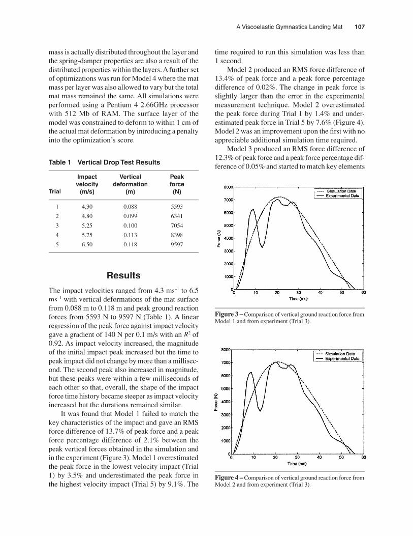
Table 1 Vertical Drop Test Results
Impact Vertical Peakvelocity deformation force
Trial (m/s) (m) (N)
1 4.30 0.088 5593
2 4.80 0.099 6341
3 5.25 0.100 7054
4 5.75 0.113 8398
5 6.50 0.118 9597
Results
The impact velocities ranged from 4.3 ms–1 to 6.5 ms–1 with vertical deformations of the mat surface from 0.088 m to 0.118 m and peak ground reaction forces from 5593 N to 9597 N (Table 1). A linear regression of the peak force against impact velocity gave a gradient of 140 N per 0.1 m/s with an R2 of 0.92. As impact velocity increased, the magnitude of the initial impact peak increased but the time to peak impact did not change by more than a millisec-ond. The second peak also increased in magnitude, but these peaks were within a few milliseconds of each other so that, overall, the shape of the impact force time history became steeper as impact velocity increased but the durations remained similar.
It was found that Model 1 failed to match the key characteristics of the impact and gave an RMS force difference of 13.7% of peak force and a peak force percentage difference of 2.1% between the peak vertical forces obtained in the simulation and in the experiment (Figure 3). Model 1 overestimated the peak force in the lowest velocity impact (Trial 1) by 3.5% and underestimated the peak force in the highest velocity impact (Trial 5) by 9.1%. The
Figure 4 – Comparison of vertical ground reaction force from Figure 4 – Comparison of vertical ground reaction force from Figure 4 –Model 2 and from experiment (Trial 3).
108 Mills, Pain, and Yeadon
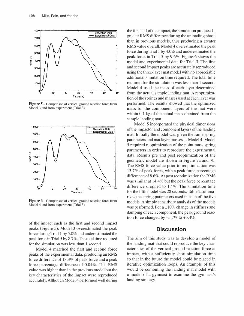
of the impact such as the fi rst and second impact peaks (Figure 5). Model 3 overestimated the peak force during Trial 1 by 5.0% and underestimated the peak force in Trial 5 by 8.7%. The total time required for the simulation was less than 1 second.
Model 4 matched the fi rst and second force peaks of the experimental data, producing an RMS force difference of 13.3% of peak force and a peak force percentage difference of 0.01%. This RMS value was higher than in the previous model but the key characteristics of the impact were reproduced accurately. Although Model 4 performed well during
the fi rst half of the impact, the simulation produced a greater RMS difference during the unloading phase than in previous models, thus producing a greater RMS value overall. Model 4 overestimated the peak force during Trial 1 by 4.0% and underestimated the peak force in Trial 5 by 9.6%. Figure 6 shows the model and experimental data for Trial 3. The fi rst and second impact peaks are accurately reproduced using the three-layer mat model with no appreciable additional simulation time required. The total time required for the simulation was less than 1 second. Model 4 used the mass of each layer determined from the actual sample landing mat. A reoptimiza-tion of the springs and masses used at each layer was performed. The results showed that the optimized mass for the component layers of the mat were within 0.1 kg of the actual mass obtained from the sample landing mat.
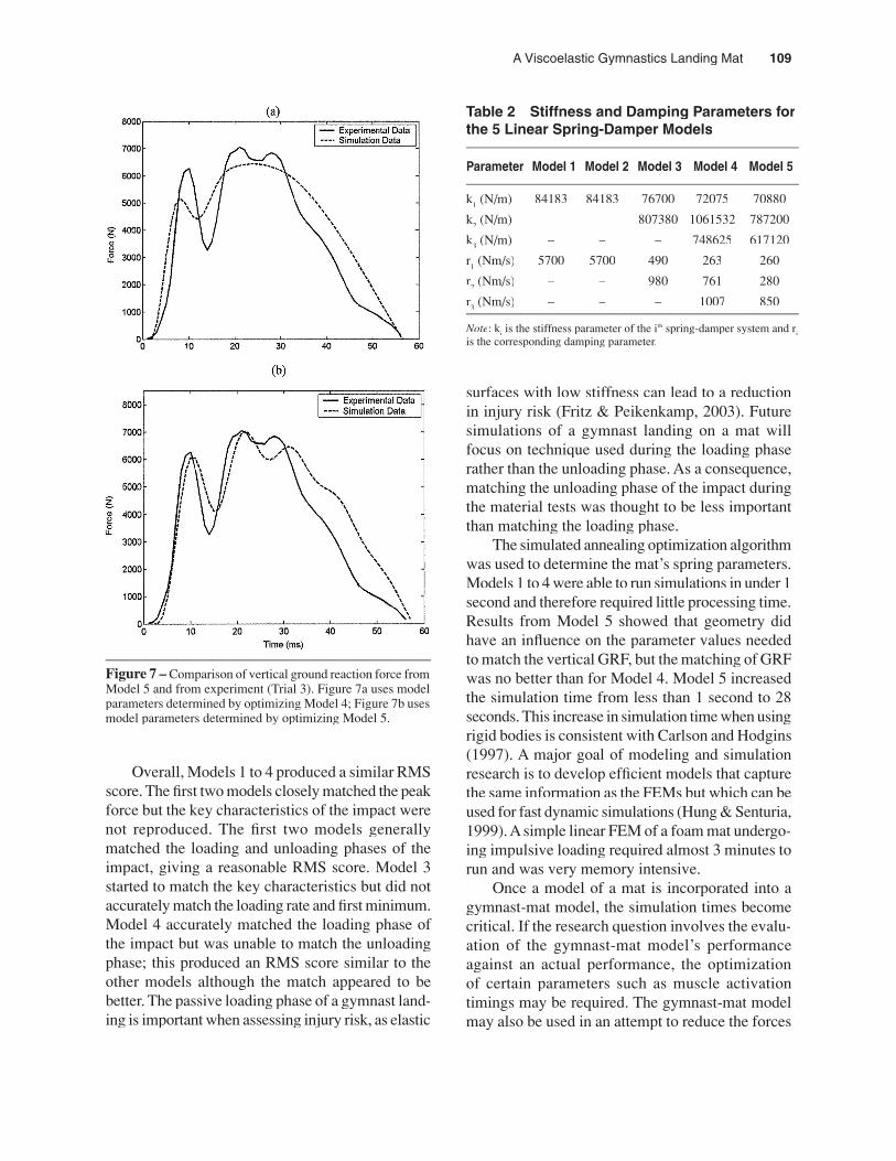
Model 5 incorporated the physical dimensions of the impactor and component layers of the landing mat. Initially the model was given the same spring parameters and mat layer masses as Model 4. Model 5 required reoptimization of the point mass spring parameters in order to reproduce the experimental data. Results pre and post reoptimization of the geometric model are shown in Figure 7a and 7b. The RMS force value prior to reoptimization was 13.7% of peak force, with a peak force percentage difference of 8.6%. At post reoptimization the RMS was similar at 14.4% but the peak force percentage difference dropped to 1.4%. The simulation time for the fi fth model was 28 seconds. Table 2 summa-rizes the spring parameters used in each of the fi ve models. A simple sensitivity analysis of the models was performed. For a ±10% change in stiffness and damping of each component, the peak ground reac-tion force changed by –5.7% to +5.4%.
Discussion
The aim of this study was to develop a model of the landing mat that could reproduce the key char-acteristics of the vertical ground reaction force at impact, with a suffi ciently short simulation time so that in the future the model could be placed in iterative optimization loops. An example of this would be combining the landing mat model with a model of a gymnast to examine the gymnast’s landing strategy.
Figure 6 – Comparison of vertical ground reaction force from Figure 6 – Comparison of vertical ground reaction force from Figure 6 –Model 4 and from experiment (Trial 3).
Figure 5 – Comparison of vertical ground reaction force from Figure 5 – Comparison of vertical ground reaction force from Figure 5 –Model 3 and from experiment (Trial 3).
A Viscoelastic Gymnastics Landing Mat 109
Table 2 Stiffness and Damping Parameters for the 5 Linear Spring-Damper Models
Parameter Model 1 Model 2 Model 3 Model 4 Model 5
k1 (N/m) 84183 84183 76700 72075 70880
k2 (N/m) – – 807380 1061532 787200
k3 (N/m) – – – 748625 617120
r1 (Nm/s) 5700 5700 490 263 260
r2 (Nm/s) – – 980 761 280
r3 (Nm/s) – – – 1007 850
Note: ki is the stiffness parameter of the ith spring-damper system and r
iis the corresponding damping parameter.
surfaces with low stiffness can lead to a reduction in injury risk (Fritz & Peikenkamp, 2003). Future simulations of a gymnast landing on a mat will focus on technique used during the loading phase rather than the unloading phase. As a consequence, matching the unloading phase of the impact during the material tests was thought to be less important than matching the loading phase.
The simulated annealing optimization algorithm was used to determine the mat’s spring parameters. Models 1 to 4 were able to run simulations in under 1 second and therefore required little processing time. Results from Model 5 showed that geometry did have an infl uence on the parameter values needed to match the vertical GRF, but the matching of GRF was no better than for Model 4. Model 5 increased the simulation time from less than 1 second to 28 seconds. This increase in simulation time when using rigid bodies is consistent with Carlson and Hodgins (1997). A major goal of modeling and simulation research is to develop effi cient models that capture the same information as the FEMs but which can be used for fast dynamic simulations (Hung & Senturia, 1999). A simple linear FEM of a foam mat undergo-ing impulsive loading required almost 3 minutes to run and was very memory intensive.
Once a model of a mat is incorporated into a gymnast-mat model, the simulation times become critical. If the research question involves the evalu-ation of the gymnast-mat model’s performance against an actual performance, the optimization of certain parameters such as muscle activation timings may be required. The gymnast-mat model may also be used in an attempt to reduce the forces
Figure 7 – Comparison of vertical ground reaction force from Figure 7 – Comparison of vertical ground reaction force from Figure 7 –Model 5 and from experiment (Trial 3). Figure 7a uses model parameters determined by optimizing Model 4; Figure 7b uses model parameters determined by optimizing Model 5.
Overall, Models 1 to 4 produced a similar RMS score. The fi rst two models closely matched the peak force but the key characteristics of the impact were not reproduced. The fi rst two models generally matched the loading and unloading phases of the impact, giving a reasonable RMS score. Model 3 started to match the key characteristics but did not accurately match the loading rate and fi rst minimum. Model 4 accurately matched the loading phase of the impact but was unable to match the unloading phase; this produced an RMS score similar to the other models although the match appeared to be better. The passive loading phase of a gymnast land-ing is important when assessing injury risk, as elastic
110 Mills, Pain, and Yeadon
experienced by the gymnast during landing, and therefore the mat parameters would require opti-mization involving many simulations. This was not a problem with the point-mass mat models, as total optimization times ranged from 2 to 4 minutes when determining spring-damper coeffi cients. This time may have been kept to a minimum, as all calcula-tions and optimizations were performed within the Matlab environment.
Increasing the model complexity by using rigid bodies (Model 5) increased the optimization time to several hours. Passing parameters in and out of visual Nastran 4D was time consuming and added to the optimization time. This was probably due to problems with the visual Nastran 4D, as it was also found that if a drop-down tool bar tab was opened in visual Nastran 4D, the simulation ran three times faster. It is possible that using different rigid body modeling software may reduce simulation time. When rigid body mat models are combined with a complex linked rigid body model of the gymnast, the simulation time may become excessive. If muscle activation timings or mat parameters need to be optimized, the total time required may become prohibitive.
When attempting to represent the deformation characteristics of a landing mat, it is possible to model the mat in varying levels of complexity. The intended use for such models should govern the model complexity. If the goal is an accurate model that incorporates the geometry of the mat and the area deformation characteristics, then a nonlinear fi nite element model may be appropriate. However, if the model of the landing mat is intended to be used as part of a larger model, such as a gymnast landing on a landing mat, a simpler model may be more appropriate. A balance must be achieved between model complexity and simulation time, but ultimately this balance depends on the intended use of the model.
The stiffness and damping values determined for these models could not be directly compared with the actual mat values. The value for the stiff-ness of the middle layer fell within the probable range, but the stiffness values for the lower layer in the models were higher than expected given the probable composition of the mats. The top layer also includes the foot soft tissue stiffness. As such the mat model should be considered more of a phenom-
enological model than a constitutive model. The mat model has also only been validated over the range of impact energies expected during the impact phase of landing with the effective mass similar to that of a male gymnast. Extrapolating the results outside of these ranges should only be done with care.
This study aimed to develop a model of the landing mat that could reproduce the key charac-teristics of the vertical ground reaction force at impact. Models 4 and 5 successfully achieved this aim. Both models reproduced the key force-time characteristics and had differences in peak forces from experimental values of between 0.01% and 10% and RMS differences of around 14%.
ReferencesButler, R., Crowell, H., & Davis, I. (2003). Lower extremity
stiffness: Implications for performance and injury. Clinical Biomechanics, 18, 511-517.
Carlson, D., & Hodgins, J. (1997). Simulation levels of detail for real-time animation. Proceeding of Graphics Interface, pp. 1-8.
Corana, A., Marchesi, M., Martini, C., & Ridella, S. (1987). Minimizing multimodal functions of continuous variables with the ‘simulated annealing’ algorithm. ACM Transac-tions on Mathematical Software, 13, 262-280.
De Koning, J.J., Nigg, B.M., & Gerritsen, K.G.M. (1997). Assessment of mechanical properties of area-elastic sport surfaces with video analysis. Medicine and Science in Sports and Exercise, 29, 1664-1668.
Devita, P., & Skelly, W. (1992). Effect of landing stiffness on joint kinetics and energetics in the lower extremity. Medi-cine and Science in Sports and Exercise, 24, 108-115.
Dura, J., Garcia, A., & Solaz, J. (2002). Testing shock absorbing materials: The application of viscoelastic linear model. Sports Engineering, 5, 9-14.
Federation Internationale de Gymnastique. (1996). Apparatus norms. Moutier, Switzerland: FIG.
Federation Internationale de Gymnastique. (2001). Code of Points—Men’s artistic gymnastics. Moutier, Switzerland: FIG.
Francis, P.R., Leigh, M., & Berzins, A. (1988). Shock absorbing characteristics of fl oors used for dance exercise. Interna-tional Journal of Sport Biomechanics, 4, 282-305.
Frederick, E. (1984). Sport shoes and playing surfaces: Their biomechanical properties. Champaign, IL: Human Kinet-ics.
Fritz, M., & Peikenkamp, K. (2003). Simulation of the infl u-ence of sports surfaces on vertical ground reaction forces during landing. Medical and Biological Engineering and Computing, 41, 11-17.
Gatto, F., Swannell, P., & Neal, R. (1992). A force-indentation relationship for gymnastic mats. Journal of Biomechanical Engineering, 114, 338-345.
A Viscoelastic Gymnastics Landing Mat 111
Hung, E., & Senturia, S. (1999). Generating effi cient dynamical models for microelectromechanical systems from a few fi nite-element simulation runs. Journal of Microelectro-mechanical Systems, 8, 280-289.
Lemmon, D., Shiang, T.Y., Hashmi, A., Ulbrecht, J.S., & Cavanagh, P.R. (1997). The effect of insoles in thera-peutic footwear—A fi nite element approach. Journal of Biomechanics, 30, 615-620.
Lyn, G., & Mills, N.J. (2002). Design of foam crash mats for head impact protection. The Engineering of Sport, 4, 1-6.
McNitt-Gray, J.L., Yokoi, T., & Millward, C. (1993). Landing strategy adjustments made by female gymnasts in response to drop height and mat composition. Journal of Applied Biomechanics, 9, 173-190.
McNitt-Gray, J.L., Yokoi, T., & Millward, C. (1994). Landing strategies used by gymnasts on different surfaces. Journal of Applied Biomechanics, 10, 237-252.
Nigg, B.M. (1985). Biomechanics, load analysis and sports injuries in the lower extremities. Sports Medicine, 2, 367-379.
Pain M.T.G., Mills, C., & Yeadon, M.R. (2005). Video analysis of the deformation and effective mass of gymnastics land-ing mats. Medicine and Science in Sports and Exercise, 37, 1754-1760.
Peikenkamp, K., Fritz, M., & Nicol, K. (2002). Simulation of vertical ground reaction force on sport surfaces during landing. Journal of Applied Biomechanics, 18, 122-134.
Ranu, H.S. (1989). The role of fi nite element modelling in bio-mechanics. In A. Yettram (Ed.), Material properties and stress analysis in biomechanics (pp. 240-249). Manchester: Manchester University Press.
Reinschmidt, C., & van den Bogert, T. (1997). A Matbal toolbox for three-dimensional kinematic analyses. Retrieved: May, 2004, from http://www.isbweb.org/software/movanal/http://www.isbweb.org/software/movanal/kinemat/index.htmlkinemat/index.html
Takei, Y. (1988). Techniques used in performing handspring and salto forward tucked in gymnastics vaulting. International Journal of Sport Biomechanics, 4, 260-281.
Takei, Y. (1998). Three-dimensional analysis of handspring with full turn vault: Deterministic model, coach’s beliefs and judges’ scores. Journal of Applied Biomechanics, 14, 190-211.
Yeadon, M.R., & Nigg, B.M. (1988). A method for the assess-ment of area-elastic surfaces. Medicine and Science in Sports and Exercise, 20, 403-407.
Zatsiorsky, V.M., & Prilutsky, B.I. (1987). Soft and stiff land-ing. Biomechanics X-B (pp. 739-743). Champaign, IL: Human Kinetics.


![Virtual Spring- Damper Mesh-Based Formation Control for … · 2018-03-28 · explored for the deployment of mobile sensors in Ref. [12]. One spring and one damper are combined as](https://img.pdfslide.net/doc/110x75/5e6782bc8062835c946a8335/virtual-spring-damper-mesh-based-formation-control-for-2018-03-28-explored-for.jpg)